HeatMaster 25 C. Installation, operating and maintenance. excellence in hot water 664Y4500 E
|
|
|
- Winfred Daniel McCormick
- 5 years ago
- Views:
Transcription


1 HeatMaster 25 C English Installation, operating and maintenance instructions excellence in hot water
2 INDEX Important notes 4 ho should read these instructions 4 Symbols 4 Recommendations 4 Certification 4 Important notes 4 Heating water recommendations 5 Generality 5 Principle of prevention 5 Installation cleaning 5 Introduction 6 orking principle 6 Technical Characteristics 7 Hot water performance 7 Frost protection 7 User guide 8 Use of the ESYS controller 8 Technical characteristics 9 General characteristics 9 Domestic hot water provision 10 Gas categories 10 Electrical connection 11 Schematic diagram 12 Installation instructions 13 Dimensions 13 Hydraulic connection 13 Boiler Room 13 Accessibility 13 2
3 INDEX Install ation 14 Flue connection 14 Gas connection 16 Domestic hot water connection 16 Central heating connection 17 Installation of a single heating circuit with regulation by ACV 22 room thermostat 18 Installation of a single heating circuit regulated by the Room Unit 20 Commissioning and Maintenance 22 Commissioning of the installation 22 Checking the settings 22 Boiler maintenance 22 Temperature sensor resistance table 22 Dismantling the burner 23 Disassembling and inspecting the electrode 23 Cleaning the exchanger 23 ESYS parameters for the specialist 24 Code mode 24 Communication mode 25 Parameter mode 26 Test Mode 28 Error Mode 29 Info mode 30 ESYS errors and blocking codes 32 List of error codes and solutions 32 3
4 Important notes ho should read these instructions These instructions should be read by: - the design engineer/consultant - the user - the installer - the service engineer All of our gas burners are tested and pre-adjusted in the factory for natural gas [equivalent to G20] Specific regulation in Belgium: The CO 2, gas flow, air flow and air/gas supply parameters are adjusted in the factory and cannot be changed in Belgium. Symbols The following symbols are used in this manual: DANGER HOT Recommendations Essential instruction for the correct operation of the installation. Essential instruction for the safety of persons and the environment. Electrocution hazard: use a qualified technician. Burn hazard. Carefully read this manual before installing and bringing the boiler into service. It is prohibited to modify the interior of the appliance in any way, without the manufacturer's prior written agreement. The boiler must be installed by a qualified engineer, in accordance with applicable local standards and regulations in force. Failure to follow the instructions describing test operations and procedures could result in personal injury or a risk of environmental pollution. In order to ensure the appliance operates safely and correctly, it is important to have it serviced by an approved installer. If there is a problem please contact your installer for advice. In spite of the strict quality standards that ACV applies to its appliances during production, inspection and transport, faults may occur. Please immediately notify your approved installer of any faults. Remember to indicate the fault code as it appears on the screen. Faulty parts must only be replaced with original factory parts. Before carrying out any work on the boiler, it is important to isolate the electrical supply to the unit. The user must not attempt to gain access to the components inside the boiler or the control panel. This appliance is not intended for use by persons with reduced physical, sensory or mental capacities, or lack of experience and knowledge (including children), unless they have been supervised or instructed concerning use of the appliance by a person responsible for their safety. Certification The appliances bear the CE mark, in accordance with the standards in force in the various countries [European Directives 92/42/EEC Efficiency, 90/396/ CEE Gas Appliances ]. These appliances also bear the Belgian gas boiler quality label HR-TOP [condensing gas boiler]. Important notes If you smell gas: - Isolate the gas supply immediately. - Ventilate the room (Open the windows). - Do not use electrical appliances and do not operate switches. - Notify your gas supplier and/or your installer immediately. This manual forms part of the items delivered with the appliance and must be given to the user to keep in a safe place! The system must be installed, commissioned, serviced and repaired by an approved installer, in accordance with current standards in force. The manufacturer declines all liability for any damage caused as a result of incorrect installation or in the event of the use of appliances or accessories that are not specified by the manufacturer. The manufacturer reserves the right to change the technical characteristics and features of its products without prior notice. The availability of certain models as well as their accessories may vary according to markets. 4
5 HEATING ATER RECOMMeNDATIONS GERALITY Filling water contains elements susceptible to damage boilers heat exchangers in case their concentration goes out of an adequate range. The risk is growing with the size of the installation since the water content per installed k increases. Those parameters has to be measured and water needs chemical treatment in case of values out of range. ACV recommends the additives from Fernox ( and from Sentinel ( Note that these products must be used in strictly accordance with the water treatment manufacturer s instructions. PRINCIPLE OF PREVTION OXYG Depending of the volume of the installation, a certain amount of oxygen is introduced in the installation. During the exploitation of the installation, some oxygen can be brought in the system in case of water re-filling and/or presence of hydraulic components without oxygen barrier (PE tubes & connectors). The oxygen reacts with the steel creating corrosion and generating sludges. hile the ACV heat exchanger is made of stainless steel and is by consequent not sensible to corrosion, the sludges generated in carbon steel part of the installation (radiators, ) will lay down in the hot parts including the heat exchanger. The sludges in the heat exchanger have the effect to reduce the water flow rate and to thermically insulate the active parts of the heat exchanger, what could lead to damages. How to prevent against oxygen? - mechanical system : an air remover combined to a sludges remover installed following the constructors specifications limits efficiently the risk of oxygen in the installation; - chemical system : additives allow the oxygen to stay in solution in the water. ACV recommends the additives from Fernox ( and from Sentinel ( note that these products must be used in strictly accordance with the water treatment manufacturer s instructions. HARDNESS Depending of the volume of the installation, the hardness of water and the possible re-filling, a certain amount of lime is introduced in the installation. The lime will lay down in the hot parts, including the heat exchanger creating a reduction of the water flow rate and a thermal insulation of the active parts of the heat exchanger. That phenomena can damage the heat exchanger. Acceptable hardness range: mmolca(hco3) 2 / l DH FH 0,5-1 2,5-5, How to prevent? the filling and re-filling water must be softened if necessary to match the working range. Additives can be used to keep the calc in solution in the water, ACV recommends the additives from Fernox ( and from Sentinel ( note that these products must be used in strictly accordance with the water treatment manufacturer s instructions. The water hardness must be check regularly and recorded in a file. OTHER PARAMETERS In addition to the oxygen and the hardness, some other parameters must be controlled in the water of heating installations. Acidity 6,6 < ph < 8,5 Conductivity Chloride Iron Cu < 400 μs/cm (a 25 C) < 125 mg/l < 0,5 mg/l < 0,1 mg/l INSTALLATION CLEANING Before filling an installation, it must be cleaned following the standard Chemical cleaners can be used, ACV recommends the additives from Fernox ( and from Sentinel ( Note that these products must be used in strictly accordance with the water treatment manufacturer s instructions. In case at least one of those recommendations can not be warranted, the boiler must be hydraulically separated of installation using plate heat exchanger 5


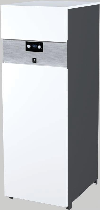
6 Introduction orking principle 1 5 Tank-in-Tank technology ACV Tank-in-Tank technology has been widely tried and tested and is extremely simple and reliable. 2 6 The core of the HeatMaster C features a ring-shaped stainless steel tank, through which the flue tubes pass. It is surrounded by a steel shell containing the primary fluid; this outer shell extends down to the combustion chamber and also surrounds the flue tubes. The primary fluid is directly heated during the combustion process and this indirectly heats the sanitary water. Like all Tank-in-Tank cylinders, the inner cylinder is corrugated along its entire height and is suspended in the boiler by the sanitary connections. 7 The heat exchange surface of the tank is much greater than that of traditional generators. A large heat exchange surface means that the Tank-in-Tank cylinders have a much shorter reheat time than traditional hot water boilers, thereby minimising the volume of water stored. The higher storage temperature in the tank is also the reason for the much higher hot water flow rates. HeatMaster 25 C 1. Cold water inlet 2. Auto-air vent 3. Stainless steel Tank-in-Tank hot water cylinder 4. Safety valve (3 bar) + pressure gauge 5. Modulating AIR/GAS premix burner 6. Domestic hot water outlet 7. Gas connection 8. Stainless steel heat exchanger 9. Heating circuit 10. Control panel 11. Expansion vessel 12. Rigid expanded polyurethane foam insulation 13. Boiler charging pump 14. Base
7 Introduction Description of the technical specifications The HeatMaster C is a hot water generator linked to a condensing boiler meeting the requirements of HR-Top standards in force in Belgium. The boiler is certified in compliance with EC standards as a room sealed appliance: C13 - C33 - C43 - C53 - C83 - C93, but it can also be connected as an open appliance in category B23 or as an appliance operating at positive pressure from the B23P category. Connection type C63 is prohibited in Belgium. Jacket The boiler is enclosed in a steel casing, which has been degreased, had a phosphate treatment process and then stove enameled at 220 C. The inside of this casing is lined with a layer of thermal and acoustic insulation, which minimizes losses. Heat exchanger The core of the HeatMaster C features a new stainless steel heat exchanger which is a result of exhaustive research and intensive laboratory tests. This reflects almost 90 years of experience in the use of stainless steel for heating and hot water generation systems. The specific geometry of the exchanger has been calculated in order to obtain a very large Reynolds number through all of its routes. The HeatMaster C thus achieves an exceptional output remaining stable throughout the boiler s lifespan, given that it does not produce any oxidation on the exchanger, which is manufactured entirely of quality stainless steel. Burner ACV uses its BG 2000-M burner for the HeatMaster C: this is a modulating air/ gas premix burner providing safe and quiet operation while limiting emissions (NOx and CO) to an incredibly low level. Although the ACV BG 2000-M burner is very modern, it uses proven technology and is manufactured using standard spare parts that are easily available on the market. Temperature control The HeatMaster C is fitted with an ESYS regulator controlled by a microprocessor, which handles the safety functions (ignition, flame monitoring, temperature limitation, etc,) and the temperature control of the boiler. The ESYS also features a weather dependent regulator. Simply connect the outdoor temperature sensor, available as an option. However, this regulator can also operate with a standard (on/off) room thermostat. The temperature of the system is then dependent on the outside conditions with compensation for the indoor temperature. Two rotating buttons placed on the control panel are accessible to the user, enabling adjustment of the temperature of the heating and domestic hot water. By entering a specific maintenance code into the unit, qualified installers may access certain parameters, in order to adapt the boiler to specific requirements. In principle, these are factory preset for all normal applications. Hot water generation In addition to its exceptional capacities for hot water production, the Tank-in-Tank system by ACV offers the following advantages: - A solution to prevent limescale deposits: the corrugations allow the tank to expand and contract during the heating cycle and thereby to prevent the build-up of limescale deposits. - Ensures that the hot water is free from legionella and bacteria: the tank is fully immersed in the primary circuit and the domestic water is permanently maintained at a uniform temperature of greater than 60 C. - Exceptional resistance to water damage and corrosion: thanks to its stainless steel design. This HeatMaster C also enables you to choose between two sanitary function methods. - Full priority mode: (factory preset) the boiler cuts the heating circuit each time the domestic circuit requires it. - Parallel mode: (only with a radiator heating circuit) the boiler functions for heating and domestic hot water at the same time. OST PROTECTION The boiler is equipped with integrated frost protection: as soon as the outlet temperature [NTC1 probe] goes below 7 C, the circulator becomes active. As soon as the outlet temperature is lower than 3 C, the burner starts up until the outlet temperature exceeds 10 C and the circulator continues to run for approximately 10 minutes. If an outdoor temperature probe is connected, the circulator is activated when the outside temperature drops below the preset threshold. 7
8 User guide Use of ESYS regulator The LCD display illustrated opposite enables visualisation of all of the boiler s functions. structure The illustration opposite represents all symbols and information that the display can show during its function. 1 7 LCD Heating system The heating system must be kept pressurised [see commissioning chapter how to determine the operating pressure]. 2 The hydraulic circuit pressure is permanently monitored by a pressure sensor. If the pressure is less than 0.8 bar the display will show LOP (Low Pressure) to indicate to you that filling of the hydraulic circuit is necessary. 3 6 For more information, please ask your installer when the system is delivered. 4 5 A In the case of repeated fills, contact your installer. ON/OFF switch Setting the temperatures A. Setting the heating temperature and summer/winter function: Range adjustable from 20 C to 90 C. hen the thermostat is positioned on, the heating circuit is deactivated and the boiler is then in summer mode. B. Adjustment of domestic hot water temperature and RESET function: Range adjustable from 20 C to 90 C. To operate the RESET function, turn the domestic hot water adjustment button to the left up to minimum, then continue to turn the button lightly and hold for 3 seconds. B 1. Numerical field displaying the temperatures 2. Temperature symbol 3. Symbol to select heating mode 4. Symbol indicating that the burner is operating 5. Symbol indicating that the DH charging pump is operating 6. Symbol to select domestic hot water mode 7. Bar symbol Fault: The temperature setting of the appliance and the safety functions of the boiler s various parts are constantly monitored by the ESYS system. If a fault occurs, the ESYS turns the unit off and displays an error code: the screen flashes and the first character is an E followed by the fault code (see list of faults). To reset the unit: - Execute the RESET function by turning the domestic setting button to the left up to minimum, then continue to turn the button lightly and hold for 3 seconds. - If the fault code appears again, contact your installer. 8
9 Technical characteristics General characteristics HeatMaster 25 C Central heating Natural Gas Propane Max. heat flow in heating mode [Input] k Max. heat flow in hot water mode [Input] k Min. heat flow [Input] k 6 6 Max. useful power 80/60 C k Min. useful power 80/60 C k Efficiency at 100% load 80/60 C % Efficiency at 100% load 50/30 C % Efficiency at 30% load [677] % Flue gases CO emissions [max power] mg/kh NOx emissions [483] mg/kh NOx class [483] 5 5 Flue gas temperature - Max output power 80/60 C C Mass flow rate of combustion products kg/h Maximum pressure loss for the ftlue Pa Maximum length of concentric flue pipe Ø 80 / 125 mm m Gas Gas flow rate G20-20 mbar m3/h 2.64 Gas flow rate G25-25 mbar m3/h 3.08 Gas flow rate G31-37 mbar m3/h 1.02 CO 2 [max power] % CO CO 2 [min power] % CO Gas connection (male) Ø 3/4" 3/4" Hydraulic parameters Maximum operating temperature C Heating circuit capacity L Capacity of the domestic circuit L Max operating pressure of the heating circuit Bar 3 3 Heat exchanger pressure drop [ T = 20 C] mbar Heating connection (female) Ø 1" 1" DH connection (male) Ø 3/4" 3/4" DH cylinder heat exchange surface m Nominal flow L/h Electrical connection Class IP Supply voltage V/Hz 230 / / 50 Maximum absorbed electrical power eight Empty (boiler packaged) kg
10 Technical characteristics Domestic hot water provision System operating at 80 C HeatMaster 25 C Peak flow rate at 40 C [ T = 30 C] L/10' 365 Peak flow rate at 40 C [ T = 30 C] L/60' 1172 Continuous flow rate at 40 C [ T = 30 C] L/hour 976 Peak flow rate at 60 C [ T = 50 C] L/10' 200 Peak flow rate at 60 C [ T = 50 C] L/60' 688 Continuous flow rate at 60 C [ T = 50 C] L/hour 586 Reheat time for domestic hot water Minutes 30 MAXIMUM OPERATING CONDITIONS Maximum operating temperature: 90 C Maximum operating pressure (tank full of water) - Primary circuit: 3 bar - Secondary circuit: 10 bar Gas categories: HeatMaster 25 C models ater quality: - Chlorides: < 150 mg/l - 6 ph 8 I2H I2L I2E I2ELL I2E(S) * I2Er I2HS I3P I3B/P G20 (mbar) G25 (mbar) G25.1 (mbar) 25 G30 (mbar) G31 (mbar) AT Austria BE Belgium CH Switzerland CY Cyprus CZ Czech republic DE Germany DK Denmark EE Estonia ES Spain France GB Great Britain GR Greece HR Croatia HU Hungary IE Ireland IT Italy LT Lithuania LU Luxembourg LV Latvia NL Netherlands NO Norway PL Poland PT Portugal RO Romania SE Sweden SI Slovenia SK Slovakia TR Turquie 10


11 Electrical connection 11
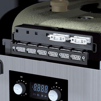
12 Safety NTC 2 NTC 1 thermostat Not 10 NTC 5 NTC 3 NTC 4 used BUS A BUS B Br Y / Gr B V B Y / Gr Y / Gr Br B Y / Gr Y / Gr Y / Gr Y / Gr Br B V Br B B B B Br R Bk Gr R Bk Gr R Bk Y Br Y Br R Bk R R Br Br Gr Gr G R Bk Bk Bk Y / Gr Y / Gr V R Bk R Bk Y Y R V Bk X X12 X15 X14 X F00 Y / Gr X2 X1 X Br B Br B Electrical connection B. Blue Bk. Black Br. Brown Gr. Green Or. Orange R. Red V. Violet. hite Y. Yellow Y/Gr. Yellow/Green Y / Gr Y / Gr Br B B V ~ 50 Hz supply 2. On/Off switch 3. Burner feed 4. Charging pump 5. Gas valve rectifier 6. Pressure sensor 7. NTC2 return sensor 8. NTC1 flow sensor 9. Connection terminal 10. Clip-in connector (option) 11. NTC5 flue-gas temperature sensor 12. Burner PM plug 13. Connection for the heating pump (not supplied) 14. ESYS programming interface 15. ESYS ON / OFF V ~ 50Hz L N PE L 13 PE N Not used 12
13 Installation instructions Dimensions A mm B mm C mm D mm HeatMaster 25 C E mm F mm G mm H mm I mm J mm Hydraulic connections HeatMaster 25 C Heating connection [F] Ø 1" DH connection [M] Ø 3/4" Gas supply [M] Ø 3/4" B C E H A Installation area - Make sure that all air vents are unobstructed. - Do not store any flammable materials in this room. - Do not store any corrosive materials, paint, solvents, salts, chlorine products or any other detergent products in the vicinity of this appliance. - If you smell gas, do not operate electrical switches, close the gas valve on the meter, ventilate the rooms and contact your installer. Accessibility The appliance must be placed in such a way that it is always easily accessible. Furthermore, the unit must have the following minimum clearance around it. G F D I J Min. 25 mm Min. 300 mm Min. Min mm mm 13
14 Installation Flue connection - The connections must comply with the NBN D standard taking into account local energy suppliers instructions, fire regulations and regulations relating to pollution. - Thanks to its built-in gas/air ratio regulator, the HeatMaster C is, to a large extent, independent of pressure drops in the air intake and flue-gas exhaust systems. However, the maximum pressure drop of this system may not be exceeded; otherwise, the output would diminish. However, the gas/air ratio regulator always guarantees optimal combustion with very low emissions. - In order to avoid any spillage of condensate via the terminal, the horizontal flue gas exhaust ducts must be installed with a sufficient degree of slope towards the boiler: 3 of slope = 5 mm per metre of duct. - There must be no obstructions or inlets to other appliances within a radius of 0.5 meters around the terminal of the HeatMaster C mm 1000 mm - The maximum pressure drop of the chimney is 130 Pascal for the HeatMaster 25 C. You can calculate this value using the following table: (please see sample calculation). Example of calculation: The diagram below consists of the following parts: pipe with a measuring point + 5 metres of vertical pipe + two 45 pipe bends + 1 metre of inclined pipe + one vertical terminal. The resistance of this system is as follows: (5 x 5.0) + (2 x 4.0) = 60.5 Pa. As this value is lower than the maximum authorised resistance, this installation is therefore compliant. Flue pressure drop chart in Pascal (1 Pascal = 0.01 mbar) Concentric pipe Separate air inlet Separate flue gas exhaust HM 25 C Ø 80/125 mm HM 25 C Ø 80 mm Straight pipe 1 m Pipe with measuring point bend bend Vertical terminal 20.0 Horizontal terminal 15.0 This table is based on ACV equipment and cannot be applied generally mm HeatMaster 25 C vent kit assembly HM 25 C Ø 80 mm 14
15 1 O 2 bar bar 3 O bar 3 O bar 3 O bar 3 O bar 3 O bar 3 O bar 3 O 4 Installation Chimney connection options B23 : Connection to an exhaust duct venting the combustion products outside of the installation area, with the combustion air being drawn directly from this area. B23P : Connection to an exhaust system of the combustion products designed to operate with positive pressure. C13 C33 B23P C43 C33 C53 B23 C43 C93 C93 C13 : Connection by pipes with horizontal terminals that simultaneously take in combustion air for the burner and discharge combustion products outside through openings that are either concentric or close enough together to be subjected to similar wind conditions. : Connection by pipes with vertical terminals that simultaneously take in fresh air for the burner and discharge the combustion products outside through openings that are either concentric or close enough together to be subjected to similar wind conditions. C93 C43 C53 C63 : Connection with an individual system of which the exhaust duct for the combustion products is installed in an exhaust pipe that is part of the building. The appliance, the exhaust duct and the terminal units are certified as an inextricable assembly. : Connection by two ducts to a collective duct system serving more than one appliance; this system of collective ducts features two ducts connected to a terminal unit that simultaneously intakes fresh combustion air and discharges the combustion products outside through openings that are either concentric or close enough together to be subjected to similar wind conditions. : Connection to separate ducts for the supply of combustion air and for venting the combustion products; these ducts may end in zones with different pressure levels. : Type C boiler which is intended for connection to a room sealed flue system which is approved and sold separately. (Prohibited in Belgium). 15
16 Installation Gas connection - HeatMaster C boilers are equipped with a Ø 3/4 M connection to connect a gas isolator. - The gas connections must comply with all applicable standards (in Belgium: NBN D51-003). - If there is a risk of dirt stemming from the gas network, place a gas filter upstream of the connection. - Purge the gas pipe and carefully check that there are no leaks on the boiler s internal and external pipes. - Check the system s gas pressure. Please refer to the technical data table. - Check the gas pressure and consumption when commissioning the appliance. Domestic hot water connection 5 The DH tank (secondary) must be vented and pressurised before filling and pressurising the heating circuit (primary). The HeatMaster C can be connected directly to the DH circuit. Flush the system before connecting the DH circuit. The system must be equipped with an approved safety unit including a 7 bar safety valve, a non-return valve and a stop valve. During the heating process, the domestic water expands and the pressure increases. As soon as the pressure exceeds the safety valve setting, the valve opens and discharges. The use of a DH expansion tank (minimum 2 litres) will avoid a discharge of water and reduce water hammer. DANGER HOT The hot water will reach temperatures greater than 60 C, which can cause burns. Therefore, the installation of a temperature control valve on the hot flow immediately after the appliance is advised. If stop valves are used in the installation, they can cause pressure waves when they are closed. To avoid this, use devices to reduce water hammer Domestic cold water isolation valve 2. Non-return valve 3. Pressure reducer 4. Safety valve 5. DH expansion vessel 6. DH temperature control valve 7. Hot water tap
17 Installation Central heating connections Recommendations The DH tank (secondary) must be vented and pressurised before filling and pressurising the heating circuit (primary). - The whole central heating system must be thoroughly flushed with clean water before being connected to the appliance. Heating connection: overview 1. Isolating valve in the heating circuit 2. Safety valve calibrated to 3 bar, with pressure gauge 3. System filling valve 4. Expansion vessel 5. Drain down valve 6. Condensate discharge 7. Heating pump - The central heating safety valve is integrated and located in the appliance. It must be connected to the drain with an air gap (allowing an inspection). - The HeatMaster 25 C consists of a 12 litre primary expansion cylinder. - A de-stratification pump is built into the appliance. This pump must operate in DH mode as well as in heating mode. The 3-way switch must be set to speed 3. - Fill the system with fresh tap water. Contact your ACV representative or installer about the use of inhibitors. - It is possible that the connections are capped due to the presence of residual water from tests carried out on the appliance. Please ensure that all the caps are removed before filling the appliance. - There is a connection and valve for filling and/or draining the appliance at the bottom of the unit behind the front panel. Fill the appliance to the minimum pressure of one bar. Purge the entire installation and refill the appliance to 1.5 bar. - Ensure that the condensate trap is fitted and connect the hose to the drain using a connection that can be inspected. If necessary fill the trap with clean water. Take the necessary precautions to prevent any risk of the condensate freezing. The connection for draining condensate must comply with current regulations. If there is a risk of low pressure in the hot water circuit (installation of HeatMaster on the roof of a building), it is essential to install a vacuum breaker device onto the cold water supply
18 Installation Installation of a single heating circuit regulated by an ACV 22 room thermostat Schematic diagram The heating system is controlled by an On/Off room thermostat. In this configuration, the boiler constantly adapts its operation (minimum temperature =60C) to the outdoor temperature, if an outside temperature sensor is connected. The circulator is triggered as soon as the room thermostat generates a heat demand. Advantages for the user: - Comfort - Maximum output - Simplicity of the system A A. - Heating temperature setting guidelines without external sensor - Maximum heating temperature limit with external sensor - The thermostat is positioned on, the heating circuit is deactivated and the boiler is then in summer mode. B. - Domestic hot water temperature setting. Code Optional equipment Description ACV 22 Room thermostat Outside temperature sensor, 12kΩ AF B Before the boiler s start up, an Auto Set is necessary so that the boiler detects the DH sensor. To do this, turn the right button to RESET then start up the boiler by pressing on the ON/OFF switch. From the time that the display shows SET the RESET button can be released. Safety thermostat RAM 5109: Mandatory to protect all floor heating circuits. 18
19 Installation Only for low temperature heating circuits BUS A BUS B It is compulsory to install a low temperature heating circuit outlet safety thermostat. Factory Description 6 Selection of the heating curve Minimum temperature of the heating outlet T plus = temperature increase of primary flow during domestic hot water mode 0 = domestic hot water priority mode 1 = in parallel ater temperature ( C) P2 = Heating curve P1 = 10 P1 = 9 P1 = External temperature ( C) P1 = 7 P1 = 6 P1 = 5 P1 = 4 P1 = 3 P1 = 2 P1 =
20 Installation Installing a single heating circuit with Room Unit regulation Schematic diagram A Room Unit thermostat controls the heating. The latter enables a choice between different heating functions and authorises up to 3 daily programmes for heating and for domestic hot water. The Room Unit thermostat has the advantage of displaying information on system status. Room Unit AF120 In this configuration, the boiler constantly adapts its operation (minimum temperature =60C) to the outdoor temperature. A A. - Heating temperature setting guidelines without external sensor - Maximum heating temperature limit with external sensor - The thermostat is positioned on, the heating circuit is deactivated and the boiler is then in summer mode. B. - Domestic hot water temperature setting. hen connected with a "Room Unit", the two knobs (A) and (B) have no action on the boiler, except for the "Reset" function. Code Optional equipment Description Before the boiler s start up, an Auto Set is necessary so that the boiler detects the DH sensor. To do this, turn the right button to RESET then start up the boiler by pressing on the ON/OFF switch. From the time that the display shows SET the RESET button can be released. RSC Room Unit: Supplied with external probe Outside temperature sensor, 12kΩ AF B For more information, consult the Room Unit instructions Safety thermostat RAM 5109: Mandatory to protect all floor heating circuits. Interface Clip-in ESYS: Authorises communication between the boiler and the RSC Room Unit. 20
21 Installation Only for low temperature heating circuits Address of the interface 0 = 0 1 BUS A BUS B It is compulsory to install a low temperature heating circuit outlet safety thermostat. Factory 10 0 Description T plus = temperature increase of primary flow during domestic hot water mode 0 = domestic hot water priority mode 1 = in parallel 1. EBV clip-in connector 2. ESYS Clip-in interface 3. ESYS Plate 21

22 commissioning and maintenance COMMISSIONING THE SYSTEM The DH tank (secondary) must be vented and pressurised before filling and pressurising the heating circuit (primary). The two circuits, DH and heating, must be filled prior to using the appliance. - Fill the DH tank slowly and purge it by opening the hot water outlet. Purge all the outlets and make sure there are no leaks in the domestic hot water system. - Fill the heating installation to at least 1.5 bar using the boiler s filling valve. Fill the system slowly. Check that the automatic air vent is operating. Check for leaks in the central heating system. - Purge the charging pump and check that it rotates. - Open the gas valve, purge the pipe and check for leaks in the system. - Ensure the condensate trap is correctly fitted underneath the boiler. - Connect the power cable to the boiler via the terminal provided and switch on the appliance. here appropriate, put the room thermostat at its highest setting. The boiler starts up. Check the gas pressure and allow the boiler to heat up for a few minutes. Set the boiler to high power mode and check the CO 2. (see table of technical characteristics). Next, set the boiler to minimum power mode and check the CO 2 (see table of technical characteristics). - Set the central heating and hot water temperatures according to the values indicated in the instructions for use. - Bleed the central heating system again, and, if required, fill to reach the desired pressure. - Make sure that the heating system is properly balanced, and, if required, adjust the valves to prevent certain circuits or radiators from getting a flow rate that is far above or below the set rate. The diameter of the condensate discharge pipe cannot be reduced. The pipe must never be obstructed. Checking the settings Specific regulation in Belgium for HeatMaster 25. The CO 2, gas flow, air flow and air/gas supply parameters are factory preset and cannot be changed Ref. 3: The OFFSET setting of the gas valve is set at the factory and sealed. It cannot be modified. - Check if the parameters are set to meet the user s needs. - Checking the boiler s settings: only an ACV-trained installer or the ACV maintenance department can perform this task. - Set the appliance to maximum power mode. - Check the dynamic gas pressure on the gas valve. (see figure below ref.1) This must be at least 18 mbar. Let the appliance heat for a few minutes until it reaches at least 60 C. Check the CO 2 setting of the appliance using a measuring instrument. The optimal value is indicated in the table of technical characteristics. To increase the CO 2 value, turn the venturi screw counter-clockwise, and turn it clockwise to decrease this value (see diagram below, ref. 2). Next, switch the appliance to minimum power mode. Let the appliance stabilize for a few minutes. Check the CO 2 value. It should be either equal to the value at full power or a maximum of 0.5 % less than it. If you observe a significant deviation, please contact ACV s maintenance department. boiler maintenance ACV recommends that you have your boiler inspected, and cleaned, if required, at least once a year. Disconnect the electrical power supply before undertaking any work on it. - Check that the condensate trap is not clogged, fill it as required and check for leaks. - Check that the safety valves are in good working order. - Vent the whole system and refill the appliance if required to 1.5 Bar. In the case of repeated fills, contact your installer. - Check the boiler s combustion in maximum power mode. If this value is very different from the original setting it may indicate an obstruction in the air intake ducts or flue gas exhaust pipes, or that the exchanger is clogged. Temperature sensor resistance table T [ C] R Ω T [ C] R Ω T [ C] R Ω

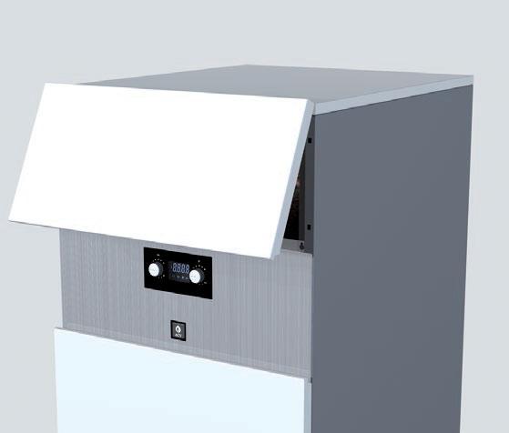
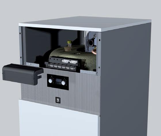
23 Commissioning and maintenance Dismantling the burner - Close the gas supply valve. - Open the top front panel of the boiler. - Remove the fan plugs, the ignition cable, the gas valve control and the ignition electrode earth. - For easier access, you can also remove the flap located on the top panel of the boiler. - Unscrew the 4 nuts of the burner using a socket and ratchet. - Unscrew the three-piece connection of the gas pipe. - To remove the burner unit, lift the fan and gas valve out in one piece. Take care not to damage the burner s insulation, which is on the inside of the exchanger. - Check the condition of the insulation and the seals and replace them if required, then put the burner back, following the above procedure in reverse order. Cleaning the exchanger - Dismantle the burner as described above. - Remove the burner insulation. - Use a vacuum cleaner to clean out the chamber. - It may also be necessary to pour water into the cylinder in order to clean out any foreign bodies located in the boiler tubes. After doing this, it is essential that the condensate trap is cleaned. - Check the burner s insulation and seal. Replace if necessary. - Check the electrode and replace if necessary. - Reassemble the burner and check for any leaks. - Power the appliance on again. Set the appliance to maximum Power mode and check for leaks of combusted gas. - Check the gas pressure and the CO 2 setting as described in the previous section. ➌ ➋ ➊ Disassembling and inspecting the electrode - Remove the earth lead connection. - Unscrew the two retaining screws. - Check the condition of the electrode and the seal, replace if necessary, before reassembling the electrode by following the above procedure in reverse order. ➍ 23
24 ESYS parameters for the specialist Code mode Max 5 sec. Max Min Min Max 24
25 ESYS parameters for the specialist Communication mode Complete communication ESYS interface Clip-in communication only No communication ½ Sec. Return 5 Sec. 25
26 ESYS parameters for the specialist Parameter mode To save the new value wait until the display stops flashing. Return ½ Sec. 5 Sec. 26
27 ESYS parameters for the specialist Factory parameter Range of parameters Description P Selection of the heating curve P Minimum temperature of the heating outlet P Minimum load P Maximum load (central heating) P P06 0 ater temperature ( C) P2 = = ON 1 = Parallel 10 T plus = outlet temperature increase during function in domestic hot water mode DH priority Heating curve P1 = External temperature ( C) P1 = 9 P1 = P1 = 7 P1 = 6 P1 = 5 P1 = 4 P1 = 3 P1 = 2 P1 =
28 ESYS parameters for the specialist Test mode Manual selection of the input in CH or DH mode from 0 to 100%. This mode is used to control combustion settings. ½ Sec. CH Mode DH Mode Return Power adjustement % Power adjustement % 5 Sec. 28
29 ESYS parameters for the specialist Error Mode ½ Sec. Return 5 Sec. 29
30 ESYS parameters for the specialist Info mode Return ½ Sec. bar 5 Sec. (30 /10) 2,4 µa rpm 0% = CH 100% = DH 30
31 ESYS parameters for the specialist Tº Heating outlet Tº Heating return Tº Domestic hot water Outside T ( C) Flue T Calculated flow T 31
32 ESYS errors and blocking codes List of error codes + solutions [in Error mode] If a fault occurs during operation, the system locks out and the screen starts to flash. The first character is an E and flashes, the following two characters indicate the code for this fault, see the chart below. To unlock the system: Press RESET on the screen. If the fault reoccurs, contact your installer. Codes Description of the fault Solution for the fault E 01 No flame presence after five start-up attempts 1. Check the wiring (short circuit in the 24 V wiring) 2. Check the electrode and its position 3. Check the burner gas level E 02 Abnormal flame signal detected 1. Check the ignition wiring 2. Check the electrode and its position 3. Replace the ESYS (water damage) E 03 E 05 E 07 E 08 E 09 Maximum thermostat open T1 or T2 > 110 C No tachometer signal from the fan Flue gas temperature too high (NTC5) No flame detection Gas valve relay error Check the link across Check the thermostat and wiring if fitted. 1. Check the NTC wiring and replace it if necessary. 2. If the NTC1 sensor is OK, check if there is water flow in the boiler 1. Check the PM connection 2. Check the fan s wiring 3. If the problem persists after two RESET attempts, replace the fan, if not, replace the ESYS circuit board. 1. Check the connection of the NTC5 sensor 2. Check the wiring of the NTC5 sensor 3. If the problem persists replace the NTC5 sensor 1. Check the electrode gap 2. Check the electrode resistance [1kΩ] E 11 Crack of sensor NTC1 or NTC2 Check the sensor NTC1 and NTC2 E 13 Remote RESET error If the problem persists after two RESET attempts, Replace the ESYS circuit board if necessary 1. Do a local RESET on the boiler. 2. If the problem persists replace the ESYS circuit board E 21 ADC error RESET the system or Replace the ESYS circuit board if necessary E 25 CRC Error RESET the system or replace the ESYS circuit board if necessary E 30 E 31 E 32 E 33 Short circuit NTC1 NTC1 open circuit Short circuit NTC3 NTC3 open circuit 1. Check the connection of the NTC1 sensor 2. Check the wiring of the NTC1 sensor 3. If the problem persists replace the NTC1 sensor 1. Check the connection of the NTC1 sensor 2. Check the wiring of the NTC1 sensor 3. If the problem persists replace the NTC1 sensor 1. Check the connection of the NTC3 sensor 2. Check the wiring of the NTC3 sensor 3. If the problem persists replace the NTC3 sensor 1. Check the connection of the NTC3 sensor 2. Check the wiring of the NTC3 sensor 3. If the problem persists replace the NTC3 sensor E 34 Deviation of the mains frequency > 1.5 Hz Check the mains frequency E 37 ater pressure Check the water pressure E 41 No communication from the water pressure sensor Check the water pressure sensor and replace if necessary 32
33 ESYS errors and blocking codes Codes Description of the fault Solution for the fault E 43 Short circuit NTC2 1. Check the connection of the NTC2 sensor 2. Check the wiring of the NTC2 sensor 3. If the problem persists replace the NTC2 sensor E 44 E 45 NTC2 open circuit Short circuit NTC5 1. Check the connection of the NTC2 sensor 2. Check the wiring of the NTC2 sensor 3. If the problem persists replace the NTC2 sensor 1. Check the connection of the NTC5 sensor 2. Check the wiring of the NTC5 sensor 3. If the problem persists replace the NTC5 sensor E 46 NTC5 open circuit 1. Check the connection of the NTC5 sensor 2. Check the wiring of the NTC5 sensor 3. If the problem persists replace the NTC5 sensor E 47 Open or defective water pressure sensor Check the water pressure sensor and replace if necessary NTC Maximal difference T1 - T2 exceeded Check the water flow rate 33
34 34
35 35
36 36
Installation, operating and maintenance instructions
 English Prestige50-75 - 120 MCA-5 Installation, operating and maintenance instructions EN 1 English INDEX Important notes 3 Who should read these instructions 3 Symbols 3 Recommendations 3 Certification
INSTALLATION, OPERATING AND SERVICING INSTRUCTIONS BG 2000-S (V13) RU PL DE IT ES NL EN 1 662Y0600 A
 RU PL DE IT ES NL EN 1 662Y0600 A") INSTALLATION, OPERATING AND SERVICING INSTRUCTIONS G 2000-S 25-35 - 45-55 60-70 - 100 (V13) 1 Index WARNINGS GAS FLOW RATE DIMSIONS SETTINGS PARAMETERS SERVICING THE URNER 3 8 13 OPERATING DESCRIPTION
INSTALLATION, OPERATING AND SERVICING INSTRUCTIONS G 2000-S 25-35 - 45-55 60-70 - 100 (V13) 1 Index WARNINGS GAS FLOW RATE DIMSIONS SETTINGS PARAMETERS SERVICING THE URNER 3 8 13 OPERATING DESCRIPTION
HeatMaster. Installation, operating and servicing instructions. HeatMaster 71 HeatMaster 101 HeatMaster 201 ENGLISH FRANCAIS NEDERLANDS ESPAÑOL
 HeatMaster ENGLISH Installation, operating and servicing instructions HeatMaster 71 HeatMaster 101 HeatMaster 201 664Y2500. EN 1 ENGLISH INDEX IMPORTANT NOTES 3 Who should read these instructions 3 Symbols
PrestigeMK2. Installation, Operating and Servicing Instructions. Prestige Solo Prestige Excellence ENGLISH FRANCAIS NEDERLANDS ITALIANO
 PrestigeMK2 Installation, Operating and Servicing Instructions Serial number higher than 40000: please see the new MCBA parameters in "Instruction for specialist MCBA-5" Prestige Solo 24-32 Prestige Excellence
PrestigeMK2. Installation, Operating and Servicing Instructions. Prestige Solo Prestige AquaSpeed Prestige Excellence ENGLISH
 ENGLISH PrestigeMK2 Installation, Operating and Servicing Instructions Prestige Solo 24-32 Prestige AquaSpeed 24-32 Prestige Excellence 24-32 EN 1 ENGLISH INDEX WARNING 3 Who should read these instructions
Installation, Operating and Servicing Instructions
 ENGLISH 0 / 0 / 0 / 0 / 00 Installation, Operating and Servicing Instructions FRANCAIS NEDERLANDS ESPAÑOL Y000.A EN ESPAÑOL NEDERLANDS FRANCAIS ENGLISH INDEX WARNING Who should read these instructions
Installation, Operating and Servicing Instructions
 EN 0 / 0 / 00 / 800 Installation, Operating and Servicing Instructions excellence in hot water EN Y000.D EN INDEX Warnings Who should read these instructions Symbols Recommendations Applicable standards
Installation, operating and servicing instructions
 English 57-115 - 144-1 - 259 Installation, operating and servicing instructions ITALIA EN 1 ITALIA English INDEX WARnINGS 3 Who should read these instructions 3 Symbols 3 Recommendations 3 Importants notes
Installation, Operating and Servicing Instructions
 ENGLISH Installation, Operating and Servicing Instructions EN 1 ENGLISH INDEX WARNINGS 3 Who should read these instructions 3 Symbols 3 Recommendations 3 Applicable standards 3 Warnings 3 INTRODUCTION
Prestige. Prestige Solo Prestige AquaSpeed Prestige Excellence Installation, Operating and Servicing Instructions
 Prestige Installation, Operating and Servicing Instructions Prestige Solo 24 32 Prestige AquaSpeed 24 32 Prestige Excellence 24 32 excellence in hot water 05/11/23 664123 INDEX INTRODUCTION 2 INSPECTION
INSTALLATION, OPERATION AND MAINTENANCE INSTRUCTIONS,
 EN INSTALLATION, OPERATION AND MAINTENANCE INSTCTIONS, for the User and the Installer HR i 320-600 - 800 A1002237-661Y1300 B EN EN TABLE OF CONTENTS GENERAL RECOMMENDATIONS...3 PRODUCT INFORMATION...4
WHE 2.24 / WHE 2.24 FF
 EN Wall-hung gas boilers WHE 2.24 WHE 2.24 FF User Guide 300011777-001-C . Contents 1 Introduction.............................................................................3 1.1 Symbols used...........................................................................................3
INSTALLATION, OPERATION AND MAINTENANCE INSTRUCTIONS BNE 1 - BNE 2 664Y6000 D
 INSTALLATION, OPERATION AND MAINTANCE INSTRUCTIONS BNE 1 - BNE 2 664Y6000 D Addendum - Additional Safety Instructions for Appliances APPLICABILITY : 664Y5000 - Rev C - N2 Condens, Installation, Operation
Installation, operation and maintenance instructions. HRi Y1300-A
 Installation, operation and maintance instructions HRi 321-601 - 800 Table of contts Geral Recommdations...4 User's Guide...5 Control Panel... 5 Appliance Description...6 Models - HRi 321 601-800... 6
INSTALLATION, OPERATION AND MAINTENANCE INSTRUCTIONS
 INSTALLATION, OPEATION AND MAINTANCE INSTUCTIONS HeatMaster 71 101 201 1 664Y6100 TALE OF CONTTS WANINS 3 Who should read these Instructions 3 Symbols 3 ecommendations 3 Warnings 3 USE UIDE 4 Use of the
BG2000S PRE-MIX GAS BURNER
 BG000S PRE-MIX GAS BURNER INSTALLATION OPERATION & MAINTENANCE DOCUMENTATION STOKVIS ENERGY SYSTEMS 96R WALTON ROAD EAST MOLESEY SURREY KT8 0DL TEL: 08707 707 77 FAX: 08707 707 767 E-MAIL:info@stokvisboilers.com
INSTALLATION, OPERATION AND MAINTENANCE INSTRUCTIONS,
 INSTALLATION, OPERATION AND MAINTENANCE INSTCTIONS, for the User and the Installer EN SMART Line SL 320-420 - 420 Duplex - 600 A002875-66Y300 A EN TABLE OF CONTENTS GENERAL RECOMMENDATIONS...4 Energy labelling...
USERS MANUAL FOR GAS BOILERS
 USERS MANUAL FOR GAS BOILERS PLEASE READ THE MANUAL CAREFULLY: IT CONTAINS IMPORTANT INFORMATION REGARDING SAFETY, INSTALLATION, USE AND MAINTENANCE OF THE APPLIANCE MODELS: NOVADENS 24 NOVADENS 24C NOVADENS
INSTALLATION, OPERATION AND MAINTENANCE INSTRUCTIONS, for the User and the Installer. SMART Line. Smart ME A Y2000 B
 INSTALLATION, OPERATION AND MAINTENANCE INSTCTIONS, for the User and the Installer SMART Line Smart ME 00-300 - 400-600 - 800 A00859-66Y000 B TABLE OF CONTENTS GENERAL RECOMMENDATIONS...4 PRODUCT INFORMATION...5
/2010 US/CA
 6 720 646 148-11/2010 US/CA (en) For the user User s Instructions Condensing gas boiler Logamax plus GB162-L.B. 80 kw/100 kw Please read thoroughly before operating This manual is available in the English
SIME FORMAT WALL HUNG BOILERS MODEL 34i AND MODEL 34e. cod A
 cod. 6272262A GENERAL DATA Heating Data Heat Output Input (Adjustable) (Adjustable) Format 34i 11.2 34KW 45 145MJ/hr Format 34e 11.2 34KW 45 145MJ/hr General Specifications FORMAT 34i 34e Main burner injectors
SMART Line Smart E
 INSTALLATION, OPERATION AND MAINTENANCE INSTCTIONS, for the User and the Installer SMART Line 30-60 - 20-240 - 300 Plus 20-240 - 300 A002858-66Y200 B TABLE OF CONTENTS GENERAL RECOMMENDATIONS...4 PRODUCT
ProCon Streamline Gas Condensing Boiler. Installation and Operating Manual.
 1 MHG Heating Ltd ProCon Streamline Gas Condensing Boiler. Installation and Operating Manual. Unit 4 Epsom Downs Metro Centre, Waterfield, Tadworth, Surrey, KT20 5LR Telephone 08456 448802 Fax 08456 448803
CAST IRON PREMIX HIGH EFFICIENCY GAS FIRED BOILER kw BRILEY DESIGN MANUAL
 BRILEY CAST IRON PREMIX HIGH EFFICIENCY GAS FIRED BOILER 60 140 kw 0604.2 Beeston Briley cast-iron premix gas-fired boiler 60-140kW Contents 1 Boiler specifications Page 3 2 Appliance general dimensions
GB24 & GB30. User Manual
 GB24 & GB30 User Manual BOILER OUTPUT To Domestic Hot Water:To Central Heating: GB24/30 Minimum 8.0 kw (27,296 Btu/h) GB24 Maximum 24.2 kw (82,570 Btu/h) GB30 Maximum 30.3 kw (103,384 Btu/h) GB24/30 Minimum
Residential Gas Condensing Boiler Greenstar ZBR16/21/28/35/42-3A... ZWB28/35/42-3A...
 70 80 99-00-O Residential Gas Condensing Boiler ZBR//8/35/4-3A... ZWB8/35/4-3A... 70 80 993 (03/03) CA/US Operating Instructions Contents Contents Key to symbols and safety instructions............................
VICTRIX 90 VICTRIX 115 Wall-hung condensing boilers for high power
 VICTRIX 90 VICTRIX 115 Wall-hung condensing boilers for high power VICTRIX 90 is the new wall-hung condensing boiler for room heating only, set-up for independent functioning and for that in cascade mode
INSTALLATION, OPERATION AND MAINTENANCE INSTRUCTIONS
 NSTALLATN, PERATN AND MANTANCE NSTRUCTNS HeatMaster 30 N 60 N 70 N 100 N 1 664Y5400 TALE F CNTTS WARNNGS 3 Who should read these nstructions 3 Symbols 3 Recommendations 3 Warnings 3 NSTALLATN 14 Package
Installation, operating and. Comfort
 EN Installation, operating and servicing instructions Comfort 00-0 - 60-20 - 20 TABLE OF CONTENTS EN GENERAL Notes Certification CE Standards Packaging SAFETY PRECAUTIONS 5 Symbols used 5 Recommdations
Gas Instantaneous Water Heater
 6 720 607 823 GB (06.06) SM Installation and Operating Instructions Gas Instantaneous Water Heater WR10..B... WR11..B... With electronic ignition and triple safety system consisting of ionisation detector,
Operating instructions
 The energy you need Operating instructions Betacom 3 24c -A (H-GB) 30c -A (H-GB) GB, IE Contents Contents 1 Safety... 3 1.1 Action-related warnings... 3 1.2 Intended use... 3 1.3 General safety information...
Superior. A Compact Floor Standing Gas Fired, High Efficiency Condensing Hot Water Boiler. Outputs 120, 160, 200, 240, 280 kw
 Superior A Compact Floor Standing Gas Fired, High Efficiency Condensing Hot Water Boiler Outputs 120, 160, 200, 240, 280 kw 1 The Superior is a, pre-assembled floor standing, gas fired high efficiency
ir-range 8G /03.15 Changes reserved.
 U s e r m a n u a l ic-range is-range ir-range 8G.52.80.00/03.15 Changes reserved. Contents 1. Introduction...3 2. Safety...5 3. Boiler description...6 4. Display and functions...7 4.1 DHW and Heating
Operating instructions
 Operating instructions Capriz 2 24c 28c GB, IE Contents Contents 1 Safety... 3 1.1 Action-related warnings... 3 1.2 Intended use... 3 1.3 General safety information... 4 2 Notes on the documentation...
1 VICTRIX ZEUS Superior kw I features
 Wall-hung condensing VICTRIX ZEUS Superior kw I is the new range of wall-hung condensing boilers with 54 litre stainless steel storage tank available in two versions with nominal heat output of 26 kw and
ENERGY TOP. Condensing boiler solutions
 ENERGY TOP Condensing boiler solutions 1 ENERGY TOP > ENERGY TOP RANGE A wide array of flexible solutions both for centralised residential application and big commercial plants The increasing need for
FLAME HEATER PYRAMID CLFH-10SS OPERATION INSTRUCTIONS
 FLAME HEATER PYRAMID CLFH-10SS OPERATION INSTRUCTIONS www.colorato.net For outdoors use only Uses propane, butane or LPG only Reflector: 47x47 mm Total Height: 2250 mm Regulator s external pressure: 28-30
Aqua Balance. User s Information Manual. WMB-155C Wall Mount Gas-Fired Combination Boiler Heating and Domestic Hot Water
 Aqua Balance WMB-155C Wall Mount Gas-Fired Combination Boiler Heating and Domestic Hot Water User s Information Manual * Low Lead Content If the information in this manual is not followed exactly, a fire
Mikrofill Ethos Condensing combination boiler. Maintenance Instructions 24cc
 Mikrofill Ethos Condensing combination boiler Maintenance Instructions 24cc IMPORTANT Benchmark Installation, Commissioning and Service Record Log Book is enclosed in your customer information pack. This
HG 675 CX 60 HG 675 CN 60 HG 675 CW 60
 HG 675 X 60 HG 675 CX 60 HG 675 CN 60 HG 675 CW 60 1 2 1. : 93/68: 90/396: 2006/95/CE: 2004/108/CE: - 1935/2004:. 2002/95/CE: RoHS 2.,.,,,,...,. (,..)..,,.,. ( ),,, ;,,.,.....,.,,,,,,...,. (..),,.,..,.,,,,
INSTALLATION, OPERATION AND MAINTENANCE INSTRUCTIONS
 NSTALLATN, PERATN AND MANTANCE NSTRUCTNS HeatMaster 00 N 00 F HeatMaster 00 N / 00 F : 664Y6300 TALE F CNTTS WARNNGS 3 Who should read these nstructions 3 Symbols 3 Warnings 3 Recommendations 3 USER S
Aqua Balance. AquaBalance TM CONTROL MODULE QUICK START GUIDE LEGEND
 Aqua Balance AquaBalance TM CONTROL MODULE QUICK START GUIDE 10 1 Domestic Hot Water temperature setpoint decreasing button 2 Domestic Hot Water temperature setpoint increasing button 3 Central Heating
Operating instructions
 Operating instructions For the operator Operating instructions HOME SYSTEM GB, IE Publisher/manufacturer Vaillant GmbH Berghauser Str. 40 D-42859 Remscheid Tel. +49 21 91 18 0 Fax +49 21 91 18 28 10 info@vaillant.de
Installation manual Tumble dryer
 Installation manual Tumble dryer T5290 Type N2... Original instructions 438 9054-00/EN 2018.02.08 Contents Contents 1 Safety Precautions...5 1.1 General safety information...7 1.2 Commercial use only...7
E-COMBI EVO E-SYSTEM EVO
 E-COMBI EVO E-SYSTEM EVO User s manual CONDENSING WALL-HUNG GAS BOILER G.C.N.:47-116-68 (24 kw) G.C.N.:47-116-69 (30 kw) G.C.N.:47-116-70 (38 kw) G.C.N.:41-116-39 (24 kw) G.C.N.:41-116-40 (30 kw) Country
12.0 Servicing. Electrode Position Fig Annual Servicing Inspection (Cont) 4 ±0.5
 4 ±0.5") 4 ±0.5 12.0 Servicing 12.2 Annual Servicing Inspection (Cont) Flame Sensing 5 ±1 10 ±1 Position Fig. 45 Spark Ignition 5. Remove the clip securing the gas feed pipe to the air/gas venturi. Disconnect the
4 ±0.5 12.0 Servicing 12.2 Annual Servicing Inspection (Cont) Flame Sensing 5 ±1 10 ±1 Position Fig. 45 Spark Ignition 5. Remove the clip securing the gas feed pipe to the air/gas venturi. Disconnect the
A/23 MFFI - A/27 MFFI
 A/23 MFFI - A/27 MFFI G.C.N. 47-6-0 / 47-6-2 Servicing Instructions Type C Boilers LEAVE THESE INSTRUCTIONS ADJACENT TO THE GAS METER TABLE OF CONTENTS Page No.. SERVICING INSTRUCTIONS. Replacement of
O. Gas boiler. Gaz 6000 W WBN H-E-N/L-S2400. Operating instructions for the end customer (2017/09) en
 en") 8 716 473 216-00.3O Gas boiler WBN 6000-30-H-E-N/L-S2400 Operating instructions for the end customer en 2 Contents Contents 1 Key to symbols and safety instructions................... 2 1.1 Key to symbols..................................
8 716 473 216-00.3O Gas boiler WBN 6000-30-H-E-N/L-S2400 Operating instructions for the end customer en 2 Contents Contents 1 Key to symbols and safety instructions................... 2 1.1 Key to symbols..................................
Installation and converting instructions to another gas type T4530, T4650
 GB, IE Read the technical installing the appliance. Read the user lighting the appliance. This appliance may only be installed in a room if the room meets the appropriate ventilation requirements specified
INSTALLATION, OPERATION AND MAINTENANCE INSTRUCTIONS,
 INSTALLATION, OPERATION AND MAINTENANCE INSTCTIONS, for the User and the Installer SMART GREEN 130-160 - 210 A1002064-661Y3000 B TABLE OF CONTENTS GENERAL RECOMMENDATIONS...4 PRODUCT INFORMATION...5 Energy
HOW TO USE YOUR 4500 RANGE L.P.G. COOKER OR HOB UNIT
 HOW TO USE YOUR 4500 RANGE L.P.G. COOKER OR HOB UNIT If the appliance does not operate correctly contact your supplier Or Leisure Products (Bolton) Ltd Holly Street, Bolton, BL1 8QR. England. ~~~~ For
The guarantee on this appliance is valid for 12 months from the first day of installation.
 Users Manual Dear Customer, Thank you for choosing an ARISTON boiler. We guarantee that your boiler is a reliable and technically sound product. This Users Manual provides detailed instructions and recommendations
User Guide Compact-7 series
 User Guide Compact-7 series Boiler-CH Calorifier Combi Introductory remarks Congratulations on the purchase of your Kabola Compact 7. Kabola has been a manufacturer of oil-fired heating systems since 1947.
Servicing manual. Wall-mounted condensing gas boiler 600 Series - 11S / 19S / 24S / 24C /2002 GB(EN) For trade use
 For trade use") GB122 7210 1300-12/2002 GB(EN) For trade use Servicing manual Wall-mounted condensing gas boiler 600 Series - 11S / 19S / 24S / 24C Please read thoroughly before attempting to diagnose fault List of contents
GB122 7210 1300-12/2002 GB(EN) For trade use Servicing manual Wall-mounted condensing gas boiler 600 Series - 11S / 19S / 24S / 24C Please read thoroughly before attempting to diagnose fault List of contents
SAGV x 1/1 GN 7-12 x 20 COMBI STEAMER FOR GASTRONOMY
 COMBI STEAMER FOR GASTRONOMY SAGV071 7 x 1/1 GN 7-12 x 20 Item AUTOCLIMA ECOSPEED FAST-DRY GFT (only for gas models) ECOVAPOR LCS CLEANING (optional) COMBI CLEAN CALFREE (*) 2 SPEED FAN (optional) SCS
AGUAdens TM 100% residential condensing D.H.W. wall-mounted water heaters ( litres) AISI 316 D.H.W. WORKING PRESSURE TITANIUM CONDENSING
 AISI 316 D.H.W. WORKING PRESSURE TITANIUM CONDENSING") MADE IN ITALY residential condensing D.H.W. up to 10 bar WORKING PRESSURE AISI 316 Ti TITANIUM D.H.W. 100% CONDENSING AGUAdens TM wall-mounted water heaters (16-22 -37 litres) AGUAdensTM INSTANTANEOUS
MADE IN ITALY residential condensing D.H.W. up to 10 bar WORKING PRESSURE AISI 316 Ti TITANIUM D.H.W. 100% CONDENSING AGUAdens TM wall-mounted water heaters (16-22 -37 litres) AGUAdensTM INSTANTANEOUS
ELECTRIC BOILERS FOR CENTRAL HEATING
 ELECTRIC BOILERS FOR CENTRAL HEATING TermoMax INSTRUCTIONS FOR INSTALLATION INSTRUCTIONS FOR INSTALLATION We reserve the right of alternations WE ARE NOT LIABLE FOR DAMAGES RESULTING FROM NON- OBSERVING
INSTALLATION, OPERATION AND MAINTENANCE INSTRUCTIONS. HeatMaster TC 664Y6800 A
 INSTALLATION, OPERATION AND MAINTENANCE INSTCTIONS HeatMaster 25-35 - 45-70 - 85-120 TC 664Y6800 A TALE OF CONTENTS GENERAL RECOMMENDATIONS...4 USER'S GUI...5 Instructions for the d user... 5 Periodic
INSTRUCTION FOR THE USER THC V E OIL BLU
 INSTRUCTION FOR THE THC V E OIL BLU CONTENTS General safety information 4 Precautions 4 Control panel 5 Mode selection 8 User levels 10 Start-up 12 Temporary shutdown 15 Preparing for extended periods
Curvation & Siesta Models
 Curvation & Siesta Models Installation, Servicing & User Instructions For use in GB & IE (United Kingdom and Ireland) This appliance has been tested and certified for other counties (see technical data).
Servicing Instructions Type C Boilers G.C.N: LEAVE THESE INSTRUCTIONS ADJACENT TO THE GAS METER
 Servicing Instructions Type C Boilers G.C.N: 4-6-0 47-6-08 47-6-09 47-6-3 LEAVE THESE INSTRUCTIONS ADJACENT TO THE GAS METER TABLE OF CONTENTS Page No.. SERVICING INSTRUCTIONS. Replacement of Parts 3.2
Remeha. Fuel oil/gas boilers P 520. Installation and Service Manual A
 Remeha Fuel oil/gas boilers EN Installation and Service Manual 300016859-001-A 63115 Declaration of conformity The appliance complies with the standard model described in declaration of compliance. It
Servicing manual. 600 Series - 11S / 19S / 24S / 24C. Wall-mounted condensing gas boiler. For trade use
 GB122 Servicing manual Wall-mounted condensing gas boiler 600 Series - 11S / 19S / 24S / 24C For trade use Please read thoroughly before attemting to diagnose fault 7217 4900 (03/2010) GB/IE List of contents
Condensing, pre-mixed, wall-hung gas boilers with water tank
 C 271-01 made in Italy Nias condensing Condensing, pre-mixed, wall-hung gas boilers with water tank Life-enhancing heat GB Condensing, pre-mixed, wall-hung boilers with water tank Nias CONDENSING HIGH
User s Information Manual
 User s Information Manual Series 2 Models 1000-2000 MBH Commercial Condensing Gas-fired water boilers If the information in this manual is not followed exactly, a fire or explosion may result, causing
DOMESTIC HOT WATER Follow operational sequence
 DOMESTIC HOT WATER Follow operational sequence Turn Winter/Summer selector to Summer position. The display is switch on. Go to section A Error 110 flashing Error 131 flashing Turn the selector to reset
TAHITI CONDENSING KR 55 - KR 85
 IST 03 C 351-01 TAHITI CONDENSING KR 55 - KR 85 GB INSTALLATION USE AND MAINTENANCE Dear Customer, Thank you for choosing and buying one of our boilers. Please read these instructions carefully. They will
Installation manual. Tumble dryers T4290, T4530, T4650. Selecta Control
 Installation manual Tumble dryers T4290, T4530, T4650 Type N4... Selecta Control Installation manual in original language 487 05 44 61/EN 2012.08.21 Contents Contents Safety precautions...5 Dimension
WARNING FOR YOUR SAFETY FOR YOUR SAFETY. Outback Patio Heaters. Patio Heaters
 Patio Heaters Outback Patio Heaters A regulator of an approved type is required to operate this unit. A regulator of 28-30mbar must be used for butane and 37mbar for propane. For more details on compatible
Mikrofill Ethos Condensing combination boiler
 Mikrofill Ethos Condensing combination boiler User Instructions 24cc CE Mark Mikrofill gas appliances comply with the requirements contained in CE Mark documents contained with European directives applicable
USER INSTRUCTIONS MERIDIAN 3 WOODY LIVE THE BRAAI LIFE GB DE DK ES FR IT NL NO PL SE SI. MODEL No: mBar. Product code: 20163
 LIVE THE BRAAI LIFE MERIDIAN 3 WOODY MODEL No: 98510 Product code: 20163 28mBar USER INSTRUCTIONS DE DK ES FR IT NL NO PL SE SI NOTE! PRODUCT MAY VARY FROM ILLUSTRATIONS 503-0630 LEV7 CAUTION Provide ample
SKOTTEL BRAAI LIVE THE BRAAI LIFE. MODEL No 8309T-13. Skottel Braai. Grill2Braai LEV8
 USER INSTRUCTIONS SKOTTEL BRAAI MODEL No 8309T-13 Skottel Braai Grill2Braai LIVE THE BRAAI LIFE 503-0399 LEV8 CAUTION For Outdoor use only! This appliance may not be used in an exterior enclosed balcony,
GAS FR25 IR FRYERS. Grande Carte SPECIFICATIONS CONSTRUCTEUR. Part A: Technical characteristics Part B: Technical instructions for installation
 Grande Carte GAS FR25 IR FRYERS SPECIFICATIONS CONSTRUCTEUR Part A: Technical characteristics Part B: Technical instructions for installation - WARNING - Installation and repairs must be carried out by
NIKE Star 24 3 E. Instantaneous wall-hung with open chamber boilers. NIKE Star 24 3 E
 Instantaneous wall-hung with open chamber boilers Small wall-mounted open chamber, conventional flue instant boiler. General features. is a wall-mounted, open combustion chamber, conventional flue generator
Installation manual Tumble dryer
 Installation manual Tumble dryer T5130, T5130C Type 1130.. Original instructions 438 9054-40/E 2018.05.29 Contents Contents 1 Safety Precautions...5 1.1 General safety information...7 1.2 Commercial use
Operating instructions
 Operating instructions For the operator Operating instructions ecotec plus Gas-fired wall-hung high-efficiency boiler GB, IE Publisher/manufacturer Vaillant GmbH Berghauser Str. 40 D-42859 Remscheid Telefon
User Manual FLOWMAX-90. for model. Condensing water heater 85,000 BTU. Installation, operating, commissioning and maintenance instructions.
 User Manual for model FLOWMAX-90 Condensing water heater 85,000 BTU WARNING If the information in these instructions is not followed exactly, a fire or explosion may result, causing property damage, personal
Clyde CK40. Cast Iron Boiler. Engineering Data Sheet 663/8 May Natural gas Class D oil Dual Fuel. 350 kw to 500 kw
 atural gas Class D oil Dual Fuel 350 kw to 500 kw Clyde CK40 Cast Iron Boiler Contents Page General information Dimensions 3 Technical data 3 Installation requirements 4 & 5 Boiler control panel 6 Wiring
TEMPRA. Wall Mounted Fan Flue System boiler. Wall mounted fanned flue boiler INSTALLATION AND USE INSTRUCTIONS. Appr. nr. B A - CE 0063 AQ 2150
 Wall Mounted Fan Flue System boiler Appr. nr. B 94.04 A - CE 0063 AQ 2150 Phone numbers: Installer Service Engineer Serial N Wall mounted fanned flue boiler INSTALLATION AND USE INSTRUCTIONS Please read
VICTRIX Superior kw Export VICTRIX Superior kw X Export
 Wall-hung condensing VICTRIX Superior kw is the instantaneous sealed chamber wallhung boiler with power of 32 kw which, thanks to condensation technology, is characterised for its high efficiency and guarantees
Installation manual Washer extractor
 Installation manual Washer extractor W555H Type W.55.H Original instructions 438 9054-30/EN 2017.11.06 Contents Contents 1 Safety Precautions...5 1.1 General safety information...6 1.2 Commercial use
CBX 24, 32 & 38 SBX 30
 751030 MANUAL (NEW) 21/9/10 08:39 Page 1 Eden X Type CBX 24, 32 & 38 SBX 30 INSTALLATION AND SERVICING INSTRUCTIONS TO BE GIVEN TO THE USER 0086 EC 87/BP/35 G.C. Appliance No. 47-260-05 (Eden CBX 24) G.C.
C Tahiti. condensing
 C 227-01 m a d e i n I ta ly Tahiti condensing Condensing, pre-mixed, wall-hung boilers KC 24 KC 28 - KC 32 indoor, instantaneous, combination boilers KR 24 KR 38 - KR 32 indoor, central heating only boilers
balanced flue appliances
 4 Harash St. Neve Neeman, Hod Hashron, 44, Israel P.O Box 73 Tel: +97-9-7488 Fax: +97-9-74687 E-mail: ortalsys@netvision.net.il balanced flue appliances USER, INSTALLATION AND SERVICING INSTRUCTIONS IMPORTANT
Installation and Operating Instructions
 Installation and Operating Instructions Models: Verso 4G Hob As part of Parmco Appliances commitment to improving and updating product ranges, we reserve the right to alter, change and update technical
USER GUIDE. IMAX XTRA EL kW. For Installation Guide see reverse of book
 USER GUIDE IMAX XTRA EL 320-620kW For Installation Guide see reverse of book When replacing any part on this appliance, use only spare parts that you can be assured conform to the safety and performance
VIESMANN. Operating instructions VITODENS 050-W. for the system user. With constant temperature or weather-compensated control unit
 Operating instructions for the system user VIESMANN With constant temperature or weather-compensated control unit VITODENS 050-W 9/2014 Please keep safe. Safety instructions For your safety Please follow
Installer manual AG-AA10. Air/air heat pump IHB GB AG-AA10-30 AG-AA10-40/50
 -30 Installer manual Air/air heat pump -40/50 IHB GB 1516-1 331554 Table of Contents 1 Important information 2 5 Installation 7 Safety information 2 Model combinations 7 Read before starting the installation
PowerVent. Installation manual (GB) English. Store this document in a safe place UK
 English. Store this document in a safe place UK") PowerVent Installation manual (GB) Store this document in a safe place 959.034.03.UK GB Contents Blz Foreword 3 1. Introduction 3 2. CE declaration 4 3. SAFETY 4 3.1 General 4 3.2 Regulations 4 3.3 Precautions
PowerVent Installation manual (GB) Store this document in a safe place 959.034.03.UK GB Contents Blz Foreword 3 1. Introduction 3 2. CE declaration 4 3. SAFETY 4 3.1 General 4 3.2 Regulations 4 3.3 Precautions
ALKON CARGO. A precise and fast delivery rate. A very high specific flow rate (20 litres per minute with Dt 25)
") ALKON CARGO ALKON CARGO model Max/min nominal output Heat input condensing Non-condensing η condensation at 30 part load 35 7,4 35,1 6,7 33,5 34,8 106,3 Efficiency class (directive 92/42) ALKON CARGO is
ALKON CARGO ALKON CARGO model Max/min nominal output Heat input condensing Non-condensing η condensation at 30 part load 35 7,4 35,1 6,7 33,5 34,8 106,3 Efficiency class (directive 92/42) ALKON CARGO is
Residential Gas Condensing Boiler Greenstar combi 100 p / 151 p ZWB28-3A... ZWB42-3A...
 Residential Gas Condensing Boiler Greenstar combi 00 p / 5 p ZWB8-3A... ZWB4-3A... Operating Instructions 708733 (07/04) US/CA Contents Contents Explanation of symbols and safety instructions.......................
Installation manual. Tumble dryers T4250, T4350. Selecta Control
 Installation manual Tumble dryers T4250, T4350 Type N2... Selecta Control Installation manual in original language 487 05 43 61/EN 2010.06.09 Contents 3 Contents The front of the dryer... 4 Safety precautions...
USER MANUAL. 60cm, 3 burners, Hob AKC 630
 USER MANUAL 60cm, 3 burners, Hob AKC 630 For your safety These instructions have been drawn up for your safety and that of others. You are therefore requested to read them carefully before installing
USER INSTRUCTIONS 2 COOK 2 PRO LIVE THE BRAAI LIFE GB DE DK ES FR IT NL NO PL SE SI. MODEL No: mBar & 50mBar DELUXE P/C: STOVE
 LIVE THE BRAAI LIFE 2 COOK 2 PRO MODEL No: 202-15 28mBar & 50mBar DELUXE P/C: 202-20 STOVE P/C: 202-30 USER INSTRUCTIONS NOTE! PRODUCT MAY VARY FROM ILLUSTRATIONS DE DK ES FR IT NL NO PL SE SI 503-0543
INSTALLATION, OPERATION AND MAINTENANCE INSTRUCTIONS
 INSTALLATION, OPERATION AND MAINTANCE INSTCTIONS BNE 2 Conds 21.8 kw 664Y5900 D TABLE OF CONTTS GERAL RECOMMDATIONS...4 USER'S GUI...5 Instructions for the d-user... 5 Periodic checks... 5 APIANCE DCRIPTION...6
24/31-28/35-33/40 kw Premix System Condensing - ErP Combi Gas Boilers. Enerwa / EnerwaPlus.
 24/31-28/35-33/40 kw Premix System Condensing - ErP Combi Gas Boilers Enerwa / EnerwaPlus www.warmhaus.com Condensing-ErP Premix System Boilers 24/31-28/35-33/40 kw Warmhaus wall-hung gas combi boilers
INSTRUCTION MANUAL GAS HOB. Model:GH600
 INSTRUCTION MANUAL GAS HOB Model:GH600 1 Contents Important Information Description of Hob Operation Maintenance and cleaning Troubleshooting Instruction for installer Technical data Important safety requirements
TermEfekt USER S MANUAL AIR HEATER. Model PGA 14
 Przedsiębiorstwo Produkcyjno-Wdrożeniowe ARAJ sp. z o.o. 55-080 Kąty Wrocławskie, ul. Mireckiego 30 POLAND USER S MANUAL AIR HEATER TermEfekt Model PGA 14 Kąty Wrocławskie, 2004 Product identification
HIGH POWER. VICTRIX PRO 2 ErP. High power, wall-hung condensation boiler
 HIGH POWER VICTRIX PRO 2 ErP High power, wall-hung condensation boiler MAIN INDEX INDEX 1 VICTRIX PRO 35-55 2 ErP SPECIFICATIONS...5 2 VICTRIX PRO 80-100-120 2 ErP SPECIFICATIONS...6 3 VICTRIX PRO 35-55
Operating instructions
 Operating instructions Gas condensing boiler WARNING: If the information in this manual is not followed exactly, a fire or explosion may result causing property damage, personal injury or loss of life.