INSTALLATION, OPERATION AND MAINTENANCE INSTRUCTIONS
|
|
|
- Pamela Washington
- 5 years ago
- Views:
Transcription


1 INSTALLATION, OPERATION AND MAINTANCE INSTCTIONS BNE 2 Conds 21.8 kw 664Y5900 D
2 TABLE OF CONTTS GERAL RECOMMDATIONS...4 USER'S GUI...5 Instructions for the d-user... 5 Periodic checks... 5 APIANCE DCRIPTION...6 TECHNICAL CHARACTERISTICS...8 Electrical Characteristics... 8 Dimsions...10 Combustion Characteristics...12 Hydraulic Characteristics...13 Chimney Connection Characteristics...14 DHW Performance...15 Maximum Operating Conditions...15 INSTALLATION...16 Package Contts...16 Tools required for the installation...16 How to move the boiler...17 Safety Instructions for the Installation...18 Recommdations for the Prevtion of Corrosion and Scaling...20 Boiler Preparation...22 Burner installation...24 Electrical Connections...26 Flue connection...27 DHW Connection...28 Heating circuit connection...29 Oil Connection BNE 2 Conds : 664Y5900 D
3 TABLE OF CONTTS STARTING UP...31 Tools required for starting up...31 Checks before starting up...31 Filling the System...32 Starting up the Boiler...33 Combustion adjustmt...33 MAINTANCE...34 Safety Instructions for the Boiler Maintance...34 Periodic boiler maintance tasks...35 Cleaning the burner and the heating body...36 Cleaning the condser...36 Cleaning the condsate trap...37 Draining the Boiler...38 Restart after maintance...39 In case of problem...39 CLARATION OF CONFORMY - EC...40 CLARATION OF CONFORMY - RD 17/7/ BNE 2 Conds : 664Y5900 D 3
4 GERAL RECOMMDATIONS NOTE This manual contains important information with respect to the installation, the starting up and the maintance of the boiler. This manual must be provided to the user, who will read it carefully and keep it in a safe place. We accept no liability should any damage result from the failure to comply with the instructions contained in this technical manual. Esstial recommdations for safety It is prohibited to carry out any modifications to the appliance without the manufacturer s prior and writt agreemt. The product must be installed by a qualified gineer, in accordance with applicable local standards and regulations. The installation must comply with the instructions contained in this manual and with the standards and regulations applicable to installations. Failure to comply with the instructions in this manual could result in personal injury or a risk of vironmtal pollution. The manufacturer declines all liability for any damage caused as a result of incorrect installation or in the evt of the use of appliances or accessories that are not specified by the manufacturer. Esstial recommdations for the correct operation of the appliance In order to sure that the appliance operates correctly, it is esstial to have it serviced by a certified installer or maintance contractor every year. In case of anomaly, please call your service gineer. Faulty parts may only be replaced by guine factory parts. 4 BNE 2 Conds : 664Y5900 D
5 USER'S GUI INSTCTIONS FOR THE D-USER Esstial recommdations for safety Do not store any flammable or corrosive products, paint, solvts, salts, chloride products and other detergt products near the appliance. This appliance can be used by childr aged from 8 years and above and persons with reduced physical, ssory or mtal capabilities or lack of experice and knowledge, only if they have be giv supervision or instruction concerning use of the appliance in a safe way and understand the hazards involved. Childr shall not play with the appliance. Cleaning and user maintance shall not be made by childr unless they are aged from 8 years and above and supervised. This appliance is not intded for use by persons (including childr) with reduced physical, ssory or mtal capabilities, unless used under the supervision of a person responsible for their safety. Childr should be supervised to sure that they do not play with the appliance. PERIODIC CHECKS Esstial recommdations for the correct operation of the appliance Check regularly that the system water pressure is at least 1 bar wh cold. If it is required to top up the system to maintain the minimum recommded water pressure, only add small amounts of water at a time. If a large amount of cold water is added in a hot boiler, the boiler can be damaged definitively. If the boiler safety cutout system is frequtly activated, contact your installer. If the system needs to be refilled repeatedly with water, please contact your installer. Regularly check that there is no water on the floor in front of the boiler. If there is, please call your installer Description 1. ON/OFF master switch of the boiler - To turn the boiler on and off. 2. Summer-winter switch - To activate or deactivate the heating pump. 3. Energy source selector switch - To activate or deactivate the heating pump and the burner, and turn on or off a 2.4 kw heating elemt to meet the need in domestic hot water. 4. Heating elemt indicator - The built-in indicator lights wh the heating elemt is activated. 5. Safety cutout warning indicator - The built-in indicator lights wh the flue gas or primary circuit water temperature is too high. 6. DHW Thermometer - Shows the temperature of the domestic hot water. 7. Domestic hot water temperature adjustmt thermostat - In DHW mode, the domestic hot water temperature can be set from 60 to 80 C. 8. Temperature and pressure gauge - Indicates the boiler temperature and the primary circuit pressure. 9. Heating temperature adjustmt thermostat - Allows to set the boiler betwe 60 and 90 C. It is recommded to set the thermostat 10 C above the set point of the domestic hot water adjustmt thermostat. 10. Pre-cut area for timer (option) - The timer allows to able/disable the domestic hot water production according to time (24 h sequce). By pushing the white tabs located around the dial, the timer can be set (1 tab = 15 min.) for a specific operation period. BNE 2 Conds : 664Y5900 D 5
. Detail of componts 1. A chimney connection with measuring port. 2. Cold water inlet 3.")
6 APIANCE DCRIPTION The BNE 2 Conds condsation fuel boiler is a heat gerator for ctral heating, with a a built-in domestic hot water preparation tank. The DHW preparation tank can operate indepdtly from the boiler thanks to a built-in heating elemt (2,4 kw). Detail of componts 1. A chimney connection with measuring port. 2. Cold water inlet 3. Domestic hot water outlet 4. Manual air bleed valve 5. Control panel 6. Safety thermostat 7. Hard expanded polyurethane foam insulation 8. Stainless steel "Tank in Tank" hot water production tank 9. Condser kw electric heating elemt 11. Combustion chamber 12. Heating circuit 13. Turbulators (6 pieces) 14. Burner chamber plate with insulation block 15. Blue flame oil burner 16. Removable panels 17. Charging pump connection 18. High-efficicy charging pump 19. Minimum thermostat Drain valve 21. Electrical plug of the boiler 22. Flue gases safety thermostat 23. Exhaust flue duct 24. Condser access door 25. Heating circuit outlet 26. Auxiliary heating circulation loop 27. Condsate trap 28. Condsate evacuation hose BNE 2 Conds : 664Y5900 D


7 APIANCE DCRIPTION BNE 2 Conds : 664Y5900 D 7
8 TECHNICAL CHARACTERISTICS ELECTRICAL CHARACTERISTICS Main electrical characteristics BNE 2 Conds Rated voltage V~ 230 Rated frequcy Hz 50 Rated currt with oil burner A 2.2 Rated currt with electrical heating elemt A 20 Electrical consumption with oil burner W 276 Electrical consumption with electrical heating elemt W 2496 IP Class IP30 Wiring diagram caption 1. ON/OFF master switch 2. Minimum thermostat Summer/winter switch 4. Safety thermostat 5. Oil burner 6. Safety cutout indicator 7. Heating elemt indicator kw electric heating elemt 9. Energy source selector switch 10. Room thermostat (option) 11. Heating pump of the system (optional) 12. Heating temp. adjustmt thermostat 13. DHW temp. adjustmt thermostat 14. Flue gas safety thermostat for flue pipe 15. Charging pump 16. Daily timer (optional) 17. Relay B : Blue Bk : Black Br : Brown G : Grey Or : Orange R : Red V : Violet W : White Y : Yellow Y/Gr : Yellow/Gre The heating elemt is composed of two 2.4 kw resistances. One of the resistances is connected through a cable and used as the main heating elemt, while the second one is a back-up that is used in case the main one fails. Never connect both resistances simultaneously or the internal cables of the boiler will be damaged. 8 BNE 2 Conds : 664Y5900 D
9 TECHNICAL CHARACTERISTICS Y/Gr Y/Gr B4 PE M 11 N PE M 15 Y/Gr 7 5 N PE S3 L1 L1 Or 17 B1 3 4 A1 1 B Or Br Or 1 t 2 2 C D 8 R Y V? 10 t 3?? Or W Or Or Bk 1 2 W P t t t t ? 9? Or? Bk Br B Y/Gr B B B B B B B Y/Gr Y/Gr Bk Bk G Or B Or Or Or G R R Br G R B R B B B Br B Y/Gr Y/Gr L1 N PE Y/Gr Y/Gr BNE 2 Conds : 664Y5900 D 9
10 TECHNICAL CHARACTERISTICS DIMSIONS Boiler Dimsions BNE 2 Conds A = Width mm 590 B = Height mm 1650 C = Depth mm 990 Volume of the combustion chamber dm³ 42.3 Height mm 295 Combustion chamber Width mm 330 Depth mm 435 Drained weight Kg mm A 51 mm 296 mm 1570 mm B 676 mm 427 mm 128 mm C 102 mm 10 BNE 2 Conds : 664Y5900 D
11 TECHNICAL CHARACTERISTICS Boiler Clearance BNE 2 Conds Recommded Minimum A (mm) B (mm) C (mm) D (mm) E (mm) C Leave a clearance to access the condser 972 D A B E BNE 2 Conds : 664Y5900 D 11
12 TECHNICAL CHARACTERISTICS COMBUSTION CHARACTERISTICS Main Characteristics BNE 2 Conds Fuel type EL fuel Max. input (PCI) kw 22.4 Output at 100% (80/60 C) kw 21.8 (50/30 C) kw 23.5 Efficicy at 30% load ( 677) % 104 Efficicy at 100% (80/60 C) % 97.5 (50/30 C) % Combustion efficicy at 100% % 98.2 Flue gas temp. at water temp. (80/60 C) C 67 (50/30 C) C 48.5 NOx (Class 5) Max. output mg/kwh 87 CO Max. output mg/kwh 4 CO 2 Max. output %CO Standby loss T = 45 K W 144 T = 30 K W 87 Maximum operating conditions of the burner in altitude Pump pressure (bar) Power (kw) Altitude (m) Power Pump pressure Area not recommded 12 BNE 2 Conds : 664Y5900 D
13 TECHNICAL CHARACTERISTICS HYDRAULIC CHARACTERISTICS Main hydraulic characteristics BNE 2 Conds Water contt of the boiler L 184 Primary circuit capacity L 67 Heating inlet/outlet connection (F) Ø 1 DHW inlet/outlet connection (M) Ø 3/4 Max. service pressure of DHW circuit bar 7 Max. service pressure of heating circuit bar 3 Primary circuit water pressure drop ( T = 20 K) mbar 20 Hydraulic pressure drop curve Pressure drop (mbar) ,5 1 1,5 2 2,5 Water flow rate (m 3 /h) BNE 2 Conds : 664Y5900 D 13
14 TECHNICAL CHARACTERISTICS CHIMNEY CONNECTION CHARACTERISTICS Chimney characteristics BNE 2 Conds Connection type B23 of boiler connection to the chimney mm 80 min. of flue pipe mm 80 L = maximum lgth of flue pipe ( 80 mm) m 9 Max. temp of flue gases C 80 Flue pipe pressure drop Pa 20 Chimney connection diagram 1 x 45 elbow 1 m straight pipe 1 x 90 elbow 1.5 m straight pipe L B23 Flue pipe lgth curve Max. lgth according to Ø of flue gas pipe Lgth of flue gas pipe (m) Area not recommded Ø of flue gas pipe (mm) 14 BNE 2 Conds : 664Y5900 D
15 TECHNICAL CHARACTERISTICS DHW PERFORMANCE Operating conditions at 80 C BNE 2 Conds Peak flow at 40 C [ T = 30 K] L/ Peak flow at 50 C [ T = 40 K] L/ Peak flow at 40 C [ T = 30 K] L/ Peak flow at 50 C [ T = 40 K] L/ Constant flow at 40 C [ T = 30 K] L/h 616 Constant flow at 50 C [ T = 40 K] L/h 475 Reheat time from 10 C to 80 C minutes 17 MAXIMUM OPERATING CONDIONS Maximum Service Pressure [DHW tank full of water] - Primary circuit :... 3 bar - DHW circuit :... 8,6 bar - Recommded safety valve (ctral heating) :... 3 bar - Recommded safety valve (DHW) :... 7 bar Mains supply pressure - Max 6 bar, without a pressure reducing valve being required (to avoid discharge of the safety pressure valve) Maximum Operating Conditions - Maximum temperature (ctral heating) : C - Maximum temperature (DHW) :... from 60 C to 80 C Water Quality See Recommdations for the Prevtion of Corrosion and Scaling. Oil quality Low sulfur oil (50 ppm) Standard oil (2000 ppm) Bio-oil 0 at 7% methyl esters of fatty acids BNE 2 Conds : 664Y5900 D 15


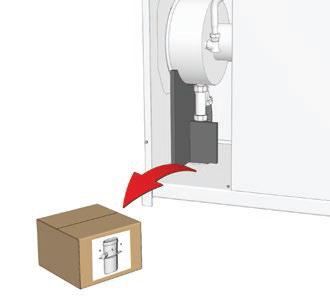
16 INSTALLATION PACKAGE CONTTS The appliances are delivered assembled, tested and packaged separately. Package 1 contts One BNE 2 Conds boiler. Installation, Operation and Maintance Instructions A stainless steel chimney connection with measuring elemt. Geral Remarks Package 2 contts A BMR 33 blue flame oil burner. Installation, Operation and Maintance Instructions The manufacturer reserves the right to change the technical characteristics and features of its products without prior notice. The availability of certain models as well as their accessories may vary according to markets. TOOLS REQUIRED FOR THE INSTALLATION 16 BNE 2 Conds : 664Y5900 D


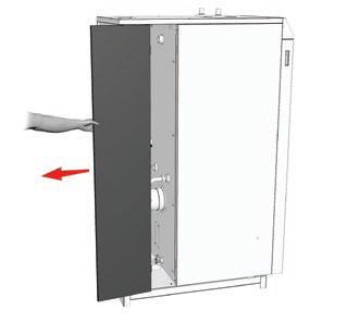
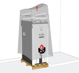
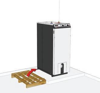
17 INSTALLATION HOW TO MOVE THE BOILER Using a hand truck Use a means of transport adapted to the boiler weight. Minimum width of the door and the hall necessary to pass the boiler A = maximum boiler width B = maximum boiler lgth C A C = Door width D = Hall width B Door height = std D A Hall width : C = x B D Example of calculation to determine the minimum hall width, with adoor width: D = 800 mm 540 C = x 1000 = Hall width 675 mm 800 Door width: D = A C x B Example of calculation to determine the minimum door width, with ahall width: D = 900 mm 540 D = x 1000 = Hall width 600 mm 900 BNE 2 Conds : 664Y5900 D 17
18 INSTALLATION SAFETY INSTCTIONS FOR THE INSTALLATION Geral remarks The connections (electrical, flue pipe, hydraulic) must be carried out in accordance with currt standards and regulations in force. If the water drawing off point is far from the tank, installing an auxiliary DHW loop can allow to get hot water more quickly at all times. Esstial recommdations for the correct operation of the appliance The boiler must be installed in a dry and protected area. Install the appliance to sure easy access at all times. To avoid any risk of corrosion, connect the stainless steel DHW production tank directly to the earth. Make sure to install a pressure reducing valve set at 4.5 bar if the mains supply pressure is in excess of 6 bar. The DHW circuit must be fitted with an approved safety group, comprised of a 7 bar safety valve, a check valve and a shut-off valve. If works need to be performed (in the boiler room or close to the air vts), make sure to turn off the boiler to prevt dust from tering and accumulating in the boiler heating system. Esstial recommdations for safety Install the boiler on a base made of non-combustible materials. Make sure that all air vts are unobstructed at all times. A condsation outlet connected to the sewer must be fitted close to the boiler to prevt the condsation products from the flue pipe from running into the boiler. The horizontal flue pipes must be installed with a slight slope of 5 cm per meter, so that the acid condsation water flows to a condsate recovery container and does not damage the heating body. Do not store any corrosive products, paint, solvts, salts, chloride products and other detergt products near the appliance. The flue pipe diameter must not be smaller than that of the boiler flue gas outlet connection. 18 BNE 2 Conds : 664Y5900 D
19 INSTALLATION Hot water can cause scalding! In the evt of small amounts of hot water repeatedly being drawn off, a stratification effect can develop in the tank. The upper hot water layer may th reach very high temperatures. ACV recommds using a pre-set thermostatic mixing valve in order to provide hot water at a maximum of 60 C. Water heated to wash clothes, dishes and for other uses can cause serious burns. In order to avoid exposure to extremely hot water that can cause serious burns, never leave childr, old people, disabled or handicapped people in the bath or shower alone. Never allow young childr to turn on the hot water or fill their own bath. The temperature of the domestic hot water can be adjusted up to 90 C in the boiler. However, the temperature of the domestic hot water at the drawing off point must comply with local regulations. (E.g. in Belgium, the maximum DHW water temperature at a drawing off point must be 75 C for boilers < 70 kw). The risk of developing bacteria exists, including Legionella pneumophila, if a minimum temperature of 60 C is not maintained in both the DHW tank and the hot water distribution network. Esstial recommdations for the electrical safety Only an approved installer is authorized to carry out the electrical connections. Install a 2-way switch and a fuse or circuit breaker of the recommded rating outside the appliance, so as to be able to shut power down wh servicing the appliance or before performing any operation on it. Isolate the external electrical supply of the appliance before performing any operation on the electrical circuit. This appliance is not intded for use by persons (including childr) with reduced physical, ssory or mtal capabilities, or lack of experice and knowledge, unless supervised or unless they have be giv instruction concerning the use of the appliance by a person responsible for their safety. BNE 2 Conds : 664Y5900 D 19
20 INSTALLATION RECOMMDATIONS FOR THE PREVTION OF CORROSION AND SCALING IN HEATING SYSTEMS How oxyg and carbonates can affect the heating system Oxyg and dissolved gasses in the water of the primary circuit contribute to the oxidation and the corrosion of the system componts that are made of ordinary steel (radiators,...). The resulting sludge is th deposited in the boiler exchanger. The combination of carbonates and carbon dioxide in the water results in the formation of scale on the hot surfaces of the installation, including those of the boiler exchanger. These deposits in the heat exchanger reduce the water flow rate and thermally insulate the exchange surfaces, which is likely to damage them. Sources of oxyg and carbonates in the heating circuit The primary circuit is a closed circuit; the water it contains is therefore isolated from the mains water. Wh maintaining the system or filling up the circuit, water rewal results in the addition of oxyg and carbonates in the primary circuit. The larger the water volume in the system, the larger the addition. Hydraulic componts without an oxyg barrier (PE pipes and connections) admit oxyg into the system. Prevtion Principles 1. Clean the existing system before installing a new boiler - Before the system is filled, it must be cleaned in accordance with standard Chemical cleaning agts can be used. - If the circuit is in bad condition, or the cleaning operation was not efficit, or the volume of water in the installation is substantial (e.g. cascade system), it is recommded to separate the boiler from the heating circuit using a plate-to-plate exchanger or equivalt. In that case, it is recommded to install a hydrocyclone or magnetic filter on the installation side. 2. Limit the fill frequcy - Limit fill operations. In order to check the quantity of water that has be added into the system, a water meter can be installed on the filling line of the primary circuit. - Automatic filling systems are not recommded. - If your installation requires frequt water refilling, make sure your system is free of water leaks. - Inhibitors may be used in accordance with standard Limit the presce of oxyg and sludge in the water - A deaerator (on the boiler flow line) combined with a dirt separator (upstream of the boiler) must be installed according to the manufacturer's instructions. - ACV recommds using additives that keep the oxyg in solution in the water, such as Fernox ( and Stinel ( products. - The additives must be used in accordance with the instructions issued by the manufacturer of the water treatmt product. 20 BNE 2 Conds : 664Y5900 D
21 INSTALLATION 4. Limit the carbonate conctration in the water - The fill water must be softed if its hardness is higher than 20 fh (11,2 dh). - Check regularly the water hardness and ter the values in the service log. - Water hardness table : Water hardness fh dh mmolca(hco3)2 / l Very soft Soft Fairly hard Hard Very hard > 42 > 23.5 > Control the water parameters - In addition to the oxyg and the water hardness, other parameters of the water must be checked. - Treat the water if the measured values are outside the range. Acidity 6,6 < ph < 8,5 Conductivity Chlorides Iron Copper < 400 μs/cm (at 25 C) < 125 mg/l < 0,5 mg/l < 0,1 mg/l BNE 2 Conds : 664Y5900 D 21

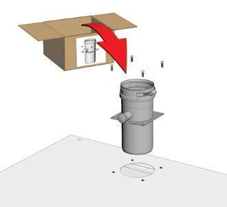
22 INSTALLATION BOILER PREPARATION BNE 2 Conds : 664Y5900 D
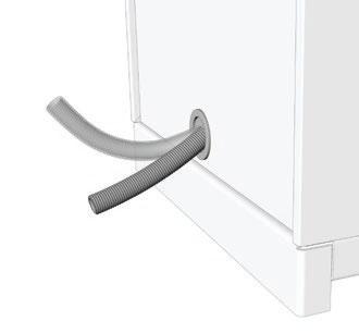
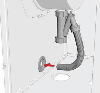
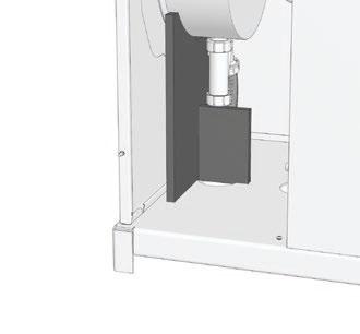
23 INSTALLATION BNE 2 Conds : 664Y5900 D 23


24 INSTALLATION BURNER INSTALLATION mm 6 24 BNE 2 Conds : 664Y5900 D


25 INSTALLATION BNE 2 Conds : 664Y5900 D 25
26 N INSTALLATION ELECTRICAL CONNECTIONS Description 1. Room thermostat 2. Heating pump of the system 3. Bridge (to be removed before connecting the room thermostat) L1 T1 T2 S3 B4 S3 T2 T1 N L1 B4 230 V ~ 50HZ L1 PE N L1 N T1 T2 S3 B4 3 M 2 t 1 26 BNE 2 Conds : 664Y5900 D
27 INSTALLATION FLUE CONNECTION Operation related to the ambit air (Type B23 Installation) To vtilate the boiler room, it is required to install- in accordance with combustion regulations - a fresh air inlet of at least 150 cm 2 or to provide a connection with other rooms to sure a fresh air supply. To get optimum sound comfort, it is recommded to: - install the boiler on a solid base (eg. concrete support) instead of a hollow base (eg. concrete blocks), which could create a resonance volume. - uncouple the boiler from the system hydraulic circuit by installing a hose connection on the inlet and outlet circuits and make sure that the hose connections are not taut or twisted. - increase the gas exhaust duct diameter if required (min 80 mm diameter). L - uncouple the gas exhaust circuit from the flue pipe wall, adding soft insulation betwe the pipe and the wall, so that the vibrations from the operating boiler are not transferred to the building walls. B23 Measuring port Measuremts of the flue gases can only be tak at the measuring port. In normal operation of the boiler, the port must be closed at all times. BNE 2 Conds : 664Y5900 D 27
28 INSTALLATION DHW CONNECTION Geral remark The circuit illustrations are basic principle diagrams only. Esstial recommdation for safety The hot water output may reach temperatures in excess of 60 C, which can cause scalding! It is therefore necessary to install a thermostatic mixing valve after the appliance. Esstial recommdations for the correct operation of the appliance Flush the system before connecting the domestic hot water circuit. Refer to the installation instructions. Make sure to install a pressure reducing valve set at 4.5 bar if the mains supply pressure is in excess of 6 bar. The installation must be fitted with an approved safety group, comprised of a 7 bar safety valve, a check valve and a shut-off valve. Typical installation Description 1. Isolating valve 2. Pressure reducing valve 3. Check valve 4. DHW expansion vessel 5. Safety valve 6. Drain valve 7. Draw-off tap 8. Grounding 9. Thermostatic mixing valve Cold water Hot water 6 28 BNE 2 Conds : 664Y5900 D
29 INSTALLATION HEATING CIRCU CONNECTION 1. Heating circuit isolating valve 2. Check valve 3. Heating pump of the system 4. Mixing valve 5. Safety group 6. Primary circuit filling valve 7. Heating circuit expansion vessel 8. Drain valve 9. Automatic air bleed valve 10. Bypass 11. Safety thermostat for floor heating circuit Do not install thermostatic valves on the radiators located in rooms fitted with a room thermostat. Heating circuit with convector Floor heating circuit t BNE 2 Conds : 664Y5900 D 29
30 INSTALLATION OIL CONNECTION Geral remark The oil connection must comply with all applicable standards. Esstial recommdation for safety Refer to the technical characteristics and safety instructions of the burner technical manual. Failure to comply with the instructions could result in damage to the material, personal injury or death. Esstial recommdations for the correct operation of the appliance Bleed the oil duct and check thoroughly if all the boiler tubes, both internal and external, are tight. Control the oil supply connection and tightness. 30 BNE 2 Conds : 664Y5900 D
31 STARTING UP SAFETY INSTCTIONS FOR STARTING UP Geral remark In normal operation, the burner starts automatically as soon as the boiler temperature drops below the preset temperature. Esstial recommdations for safety The componts inside the control panel may only be accessed by an approved installer. Set the water temperature in accordance with usage and local plumbing codes. TOOLS REQUIRED FOR STARTING UP CHECKS BEFORE STARTING UP Esstial recommdation for safety Check the tightness of the flue pipe connections. Esstial recommdation for the correct operation of the appliance Control the tightness of the hydraulic circuit connections. BNE 2 Conds : 664Y5900 D 31
32 STARTING UP FILLING THE SYSTEM First put the DHW tank under pressure before pressurizing the heating (primary) circuit. Filling the domestic hot water circuit 1. Op the isolating valves (1) and the draw-off tap (2). 2. Once the water flow rate has stabilized and the air is totally evacuated from the system, close the draw-off tap (2) Check all the connections for leaks. Cold water Hot water Preliminary filling of the heating circuit Fill the primary circuit with mains water until you reach an approximate pressure of 1,5 bar in the system. Bleed the whole system. 32 BNE 2 Conds : 664Y5900 D
33 STARTING UP STARTING UP THE BOILER Set-up conditions All connections made External power supply abled Oil supply op DHW and heating circuits full of water Procedure 1. Put the ON/OFF master switch to ON 2. Rotate the boiler control thermostat clockwise to gerate a heat demand. 3. Possibly increase the set temperature of the room thermostat, if installed. If the boiler charging pump does not work, the boiler can be damaged and its life reduced. 4. Check with your hand (motor vibrations) that the charging pump is not blocked and unblock it if required. Follow-on tasks Adjust the combustion,see paragraph below. COMBUSTION ADJUSTMT Set-up conditions Operating boiler Procedure 1. Refer to the starting up instructions detailed in the technical manual. of your burner 2. Adjust CO2 in a range of 13 to 14 % by setting the oil pressure as well as the shutter as described in the Starting up paragraph of the boiler (see the burner manual). 3. Check the flue temperature and CO contts at the measuring port (see below). Ø < 30 mm Flue gas temperature measuremt port Follow-on tasks Reinstall the measuring port plug after the check. Bleed the heating circuit again to restore a 1.5 bar pressure. Repeat the sequce until complete evacuation of the air contained in the circuit. BNE 2 Conds : 664Y5900 D 33
34 MAINTANCE SAFETY INSTCTIONS FOR THE BOILER MAINTANCE Esstial recommdation for the electrical safety Isolate the external power supply of the appliance before performing any operation, unless it is required to take measuremts or perform system setup. Esstial recommdations for safety Water flowing out of the drain valve may be extremely hot and could cause severe scalding. Check the tightness of the flue pipe connections. Esstial recommdations for the correct operation of the appliance It is recommded to have the boiler and the burner serviced at least once a year or every 1,500 hours. More frequt servicing may be required depding on boiler use. Please consult your installer for advice. The boiler and burner maintance will be carried out by a qualified gineer, and the defective parts may only be replaced by guine factory parts. Control the tightness of the hydraulic circuit connections. Make sure to replace the gaskets of the removed items before reinstalling them. 34 BNE 2 Conds : 664Y5900 D
35 MAINTANCE PERIODIC BOILER MAINTANCE TASKS Frequcy Tasks Periodic inspection 1 year 2 years 1. Make sure that the system water pressure is at least 1 bar wh cold. Top up the system if necessary, adding small quantities of water at a time. In case of repeated fills, call your installer. End-user X Professional X 2. Check that there is no water on the floor in front of the boiler. Call your installer if there is. X X 3. Check the presce of a flame through the flame sight glass. If there is no flame, see the burner manual. X X 4. Check that the charging pump is running by placing a hand on it. 5. Check the correct operation of all thermostats and safety devices: boiler thermostat, safety thermostat, safety valves, etc. X X 6. Check that the the oil connections are tight and there is no leak, that the hoses are not kinked and that there is not trance of air in the circuit. X 7. Check that all hydraulic and electrical connections are correctly fasted and tight. X 8. Check the flue gas exhaust: correct fasting, correct installation, no leaks or clogging. 9. Check the combustion parameters (CO and CO2), see "Combustion adjustmt", page 33 X X 10. Clean the burner and the heating body, see "Cleaning the burner and the heating body", page 36 and the burner manual. 11. Check the cleanliness of the condsate trap. If it is very dirty, first clean the condser, see "Cleaning the condser", page 36, th the condsate trap, see "Cleaning the condsate trap", page 37. X X 12. Clean the condser, see "Cleaning the condser", page 36. X 13. Clean the condsate trap, see "Cleaning the condsate trap", page 37. X BNE 2 Conds : 664Y5900 D 35
36 MAINTANCE It is recommded to stop the boiler and have it serviced during good weather conditions. CLEANING THE BURNER AND THE HEATING BODY Set-up conditions Boiler shut-down External power supply isolated Oil supply closed Procedure 1. Op the front panel. 2. Release the burner flange and place the burner in the maintance position to clean it (see the burner manual). 3. Remove the burner 4. Op the heating body door. 5. Using a brush, clean the soot that may be prest in the heating body and on the turbulators. 6. Check the correct position of the braid. Follow-on tasks Close the door and tight with sufficit torque to sure it is sealed against combustion products. Reinstall the burner flange and the burner. Close the front panel. CLEANING THE CONDSER Set-up conditions Boiler shut-down External power supply isolated Oil supply closed Procedure 1. Disconnect the flue pipe at the flue exhaust duct connection. 2. Inspect the inside and clean as required: If the condser is moderately dirty, pour a mixture of water and liquid soap (dish-washing type). If the condser is very dirty, op the rear side panel, or the rear panel (A), to access the condser. Op the condser (B) and clean it using a synthetic bristle brush. Do not use the same brush as the one used to clean the heating body to prevt any risks of corrosion. 36 BNE 2 Conds : 664Y5900 D


37 MAINTANCE A B Follow-on tasks 1. Close the condser and the rear panels, and reconnect the flue pipe. CLEANING THE CONDSATE TRAP Set-up conditions Boiler shut-down External power supply isolated Oil supply closed Procedure 1. Release the condsate trap ring. 2. Make sure that the condsate outlet pipe is not clogged 3. Clean the condsate trap with water and soap. 4. Make sure to leave ough water in the condsate trap before reinstallation or pour 20 cl water in the condser after reinstallation. 5. Insert the condsate trap into the condser outlet. Replace O-ring as required. 6. Maintain the condsate trap in position while tighting the ring. Pull the condsate trap downwards to check it is firmly set. Follow-on tasks Make sure to reinstall the condsate outlet pipe with a sufficit slope to allow the condsates to flow down.. Put the boiler back into service, see "Restart after maintance", page 39. BNE 2 Conds : 664Y5900 D 37
38 MAINTANCE DRAINING THE BOILER Before draining the DHW tank, drain the heating (primary) circuit or bring its pressure to 0 bar. Water flowing out of the drain valve may be extremely hot and could cause severe scalding. Keep people away from the hot water discharge. Set-up conditions Boiler switched off using the ON/OFF master switch External power supply isolated Fuel/gas supply closed 3 Heating circuit draining procedure 1. Close the isolating valves (1). 2. Connect the drain valve (2) to the sewer with a hose. 3. Op the drain valve (2) to empty the heating circuit of the boiler. 4. Op the circuit air bleed valve (3) to accelerate the draining process. 5. Close the drain valve (2) and the air bleed valve (3) once the heating circuit of the boiler is empty DHW circuit draining procedure Cold water Hot water Before draining the DHW tank, make sure that the heating (primary) circuit pressure is null Op fully a draw-off tap (3) for about 60 minutes to make sure that the DHW tank has cooled down. 2. Close the isolating valves (1). 3. Connect the drain valve (2) to the sewer with a hose. 4. Op the drain valve (2) and drain the DHW tank water to the sewer. 5. Op the draw-off tap (3) to accelerate the draining process. If it is located lower than the tank connection, op a draw-off tap located higher in the system. 6. Close the drain valve (2) and the draw-off tap (3) once the DHW tank of the boiler is empty BNE 2 Conds : 664Y5900 D

39 MAINTANCE RTART AFTER MAINTANCE Set-up conditions All removed componts reinstalled All connections made Oil supply op DHW and heating circuits full of water Procedure 1. Energize the appliance and switch it on. 2. Set the appliance at maximum power and check the absce of burned gas leaks. 3. Check the correct operation of the charging pump. 4. Check the oil pressure and CO 2 adjustmt in accordance with procedure "Combustion adjustmt", page 33. IN CASE OF PROBLEM... In case of problem, please contact you ACV represtative and provide the appliance part number and serial number, writt on the type plate. Boiler Marking Location: at the back of the appliance. The part number (Code) and serial number (N ) of the appliance are writt on the type plate and must be provided to ACV in the case of a warranty claim.. If they are not provided, the warranty claim shall be void. BNE 2 Conds : 664Y5900 D 39
40 CLARATION OF CONFORMY - EC 40 BNE 2 Conds : 664Y5900 D
41 CLARATION OF CONFORMY - RD 17/7/2009 BNE 2 Conds : 664Y5900 D 41
42 MARKINGS LABELS Pding approval 42 BNE 2 Conds : 664Y5900 D
SMART Line Smart E
 INSTALLATION, OPERATION AND MAINTENANCE INSTCTIONS, for the User and the Installer SMART Line 30-60 - 20-240 - 300 Plus 20-240 - 300 A002858-66Y200 B TABLE OF CONTENTS GENERAL RECOMMENDATIONS...4 PRODUCT
INSTALLATION, OPERATION AND MAINTENANCE INSTRUCTIONS,
 EN INSTALLATION, OPERATION AND MAINTENANCE INSTCTIONS, for the User and the Installer HR i 320-600 - 800 A1002237-661Y1300 B EN EN TABLE OF CONTENTS GENERAL RECOMMENDATIONS...3 PRODUCT INFORMATION...4
INSTALLATION, OPERATION AND MAINTENANCE INSTRUCTIONS,
 INSTALLATION, OPERATION AND MAINTENANCE INSTCTIONS, for the User and the Installer EN SMART Line SL 320-420 - 420 Duplex - 600 A002875-66Y300 A EN TABLE OF CONTENTS GENERAL RECOMMENDATIONS...4 Energy labelling...
INSTALLATION, OPERATION AND MAINTENANCE INSTRUCTIONS, for the User and the Installer. SMART Line. Smart ME A Y2000 B
 INSTALLATION, OPERATION AND MAINTENANCE INSTCTIONS, for the User and the Installer SMART Line Smart ME 00-300 - 400-600 - 800 A00859-66Y000 B TABLE OF CONTENTS GENERAL RECOMMENDATIONS...4 PRODUCT INFORMATION...5
Installation, operation and maintenance instructions. HRi Y1300-A
 Installation, operation and maintance instructions HRi 321-601 - 800 Table of contts Geral Recommdations...4 User's Guide...5 Control Panel... 5 Appliance Description...6 Models - HRi 321 601-800... 6
INSTALLATION, OPERATION AND MAINTENANCE INSTRUCTIONS,
 INSTALLATION, OPERATION AND MAINTENANCE INSTCTIONS, for the User and the Installer SMART GREEN 130-160 - 210 A1002064-661Y3000 B TABLE OF CONTENTS GENERAL RECOMMENDATIONS...4 PRODUCT INFORMATION...5 Energy
INSTALLATION, OPERATION AND MAINTENANCE INSTRUCTIONS BNE 1 - BNE 2 664Y6000 D
 INSTALLATION, OPERATION AND MAINTANCE INSTRUCTIONS BNE 1 - BNE 2 664Y6000 D Addendum - Additional Safety Instructions for Appliances APPLICABILITY : 664Y5000 - Rev C - N2 Condens, Installation, Operation
INSTALLATION, OPERATION AND MAINTENANCE INSTRUCTIONS
 EN INSTALLATION, OPERATION AND MAINTENANCE INSTCTIONS for the Installer and the User N - N2 - N3 eco A00570-664Y7700 B EN TABLE OF CONTENTS GENERAL RECOMMENDATIONS...3 USER S GUI...4 Meaning of Symbols...4
INSTALLATION, OPERATION AND MAINTENANCE INSTRUCTIONS. HeatMaster TC 664Y6800 A
 INSTALLATION, OPERATION AND MAINTENANCE INSTCTIONS HeatMaster 25-35 - 45-70 - 85-120 TC 664Y6800 A TALE OF CONTENTS GENERAL RECOMMENDATIONS...4 USER'S GUI...5 Instructions for the d user... 5 Periodic
INSTALLATION, OPERATION AND MAINTENANCE INSTRUCTIONS,
 INSTALLATION, OPERATION AND MAINTENANCE INSTCTIONS, for the User and the Installer SMART Line SL 320-420 - 420 Duplex - 600 A1004777-661Y3100 B TABLE OF CONTENTS GENERAL RECOMMENDATIONS...4 Energy labelling...
Installation, operating and. Comfort
 EN Installation, operating and servicing instructions Comfort 00-0 - 60-20 - 20 TABLE OF CONTENTS EN GENERAL Notes Certification CE Standards Packaging SAFETY PRECAUTIONS 5 Symbols used 5 Recommdations
INSTALLATION, OPERATION AND MAINTENANCE INSTRUCTIONS, for the User and the Installer. SMART Line. Smart ME A Y2000 C
 INSTALLATION, OPERATION AND MAINTANCE INSTCTIONS, for the User and the Installer SMART Line Smart ME 00-300 - 400-600 - 800 A1003499-661Y000 C TABLE OF CONTTS GERAL RECOMMDATIONS...4 PRODUCT INFORMATION...5
Prestige Solo
 INSTALLATION, OPEATION AND MAINTANCE INSTCTIONS for the Installer and the User Prestige 4-50 - 75-00 - 0 Solo A00500-664600 F TALE OF CONTTS GEAL ECOMMDATIONS... Safety Instructions... USE S GUI...4 Meaning
Installation, Operating and Servicing Instructions
 EN 0 / 0 / 00 / 800 Installation, Operating and Servicing Instructions excellence in hot water EN Y000.D EN INDEX Warnings Who should read these instructions Symbols Recommendations Applicable standards
Installation, Operating and Servicing Instructions
 ENGLISH 0 / 0 / 0 / 0 / 00 Installation, Operating and Servicing Instructions FRANCAIS NEDERLANDS ESPAÑOL Y000.A EN ESPAÑOL NEDERLANDS FRANCAIS ENGLISH INDEX WARNING Who should read these instructions
INSTALLATION, OPERATION AND MAINTENANCE INSTRUCTIONS
 INSTALLATION, OPEATION AND MAINTANCE INSTCTIONS for the Installer and the User Prestige 4-3 Solo 4-3 Excellce Prestige 4-3 Solo/Excellce : A004335-6646700 D TALE OF CONTTS GEAL ECOMMDATIONS...3 Safety
INSTALLATION, OPERATING AND SERVICING INSTRUCTIONS BG 2000-S (V13) RU PL DE IT ES NL EN 1 662Y0600 A
 RU PL DE IT ES NL EN 1 662Y0600 A") INSTALLATION, OPERATING AND SERVICING INSTRUCTIONS G 2000-S 25-35 - 45-55 60-70 - 100 (V13) 1 Index WARNINGS GAS FLOW RATE DIMSIONS SETTINGS PARAMETERS SERVICING THE URNER 3 8 13 OPERATING DESCRIPTION
INSTALLATION, OPERATING AND SERVICING INSTRUCTIONS G 2000-S 25-35 - 45-55 60-70 - 100 (V13) 1 Index WARNINGS GAS FLOW RATE DIMSIONS SETTINGS PARAMETERS SERVICING THE URNER 3 8 13 OPERATING DESCRIPTION
Operating Instructions
 EN Operating Instructions 5 6 4 3 7 2 1 8 10 9 WK 30M UK 220-240V 3000W 2 PARTS AND FEATURES 1. Water gauge 2. Kettle 3. Spout 4. Limescale filter (removable) 5. Lid 6. Lid oping button 7. Handle 8. Switch
Installation, operating and servicing instructions
 English 57-115 - 144-1 - 259 Installation, operating and servicing instructions ITALIA EN 1 ITALIA English INDEX WARnINGS 3 Who should read these instructions 3 Symbols 3 Recommendations 3 Importants notes
INSTALLATION, OPERATION AND MAINTENANCE INSTRUCTIONS
 NSTALLATN, PERATN AND MANTANCE NSTRUCTNS HeatMaster 30 N 60 N 70 N 100 N 1 664Y5400 TALE F CNTTS WARNNGS 3 Who should read these nstructions 3 Symbols 3 Recommendations 3 Warnings 3 NSTALLATN 14 Package
INSTALLATION, OPERATION AND MAINTENANCE INSTRUCTIONS
 INSTALLATION, OPERATION AND MAINTANCE INSTCTIONS for the Installer and the User HeatMaster 5-5 - 45-70 - 85-0 TC A00477-6646900 D Adddum - iring Diagrams - Detail of X00 Terminal APICAIL : 664900 - Rev
INSTALLATION, OPERATION AND MAINTENANCE INSTRUCTIONS
 INSTALLATION, OPERATION AND MAINTANCE INSTCTIONS for the Installer and the User Compact Conds 170-210 - 250-300 A1003043-664Y7200 B Adddum - Additional Safety Instructions for Gas Appliances APICABILY
INSTALLATION, OPERATION AND MAINTENANCE INSTRUCTIONS
 NSTALLATN, PERATN AND MANTANCE NSTRUCTNS HeatMaster 00 N 00 F HeatMaster 00 N / 00 F : 664Y6300 TALE F CNTTS WARNNGS 3 Who should read these nstructions 3 Symbols 3 Warnings 3 Recommendations 3 USER S
HeatMaster 25 C. Installation, operating and maintenance. excellence in hot water 664Y4500 E
 HeatMaster 25 C English Installation, operating and maintenance instructions excellence in hot water INDEX Important notes 4 ho should read these instructions 4 Symbols 4 Recommendations 4 Certification
INSTALLATION & MAINTENANCE MANUAL
 INSTALLATION & MAINTENANCE MANUAL EcO 3 Ice ANTIMICROBIAL PROTECTION FOR COMMERCIAL ICE MACHINES MODEL: X1 X4 X8 X16 Model X4 Shown IMPORTANT SAFETY INFORMATION DANGER WARNING CAUTION NOTICE EXPLANATION
ELECTRIC BOILERS FOR CENTRAL HEATING
 ELECTRIC BOILERS FOR CENTRAL HEATING TermoMax INSTRUCTIONS FOR INSTALLATION INSTRUCTIONS FOR INSTALLATION We reserve the right of alternations WE ARE NOT LIABLE FOR DAMAGES RESULTING FROM NON- OBSERVING
TABLE OF CONTENTS. Site preparation 2 Placement. 2 Chimney and stove pipe connections. 2
 TABLE OF CONTENTS SECTION TITLE PAGE 1. SITE PREPARATION AND INSTALLATION Site preparation 2 Placement. 2 Chimney and stove pipe connections. 2 Installation. 3 Water supply and return.. 3 Pressure/relief
WHE 2.24 / WHE 2.24 FF
 EN Wall-hung gas boilers WHE 2.24 WHE 2.24 FF User Guide 300011777-001-C . Contents 1 Introduction.............................................................................3 1.1 Symbols used...........................................................................................3
Installation, operating and maintenance instructions
 English Prestige50-75 - 120 MCA-5 Installation, operating and maintenance instructions EN 1 English INDEX Important notes 3 Who should read these instructions 3 Symbols 3 Recommendations 3 Certification
INSTALLATION AND OPERATING INSTRUCTIONS KLIMA
 INSTALLATION AND OPERATING INSTRUCTIONS KLIMA - 1 - CONTENTS 1.- PRESENTATION... 2 2.- LIST OF COMPONENTS... 3 3.- CONTROL ELEMENTS... 4 4.- INSTALLATION INSTRUCTIONS... 5 4.1 LOCATION... 5 4.2 FLUE...
Residential Gas Condensing Boiler Greenstar ZBR16/21/28/35/42-3A... ZWB28/35/42-3A...
 70 80 99-00-O Residential Gas Condensing Boiler ZBR//8/35/4-3A... ZWB8/35/4-3A... 70 80 993 (03/03) CA/US Operating Instructions Contents Contents Key to symbols and safety instructions............................
Installation, operation and care. Pellmax UB. Burner not included Replaces:
 Installation, operation and care Burner not included 2011-11-11 ver: Replaces: Contents 11.11 otes...3 General...4 Function...4 Technical data...5 System principle Pellmax with radiator and tank-in-tank
ProCon Streamline Gas Condensing Boiler. Installation and Operating Manual.
 1 MHG Heating Ltd ProCon Streamline Gas Condensing Boiler. Installation and Operating Manual. Unit 4 Epsom Downs Metro Centre, Waterfield, Tadworth, Surrey, KT20 5LR Telephone 08456 448802 Fax 08456 448803
GB24 & GB30. User Manual
 GB24 & GB30 User Manual BOILER OUTPUT To Domestic Hot Water:To Central Heating: GB24/30 Minimum 8.0 kw (27,296 Btu/h) GB24 Maximum 24.2 kw (82,570 Btu/h) GB30 Maximum 30.3 kw (103,384 Btu/h) GB24/30 Minimum
90 t Technical information
 90 t Technical information 2466 270+1091 1028 MAX 5m 28mm 1066 111 1030 2069 2m 1070 12V 4m 1,55m 90 270 90 t 1 2 6,3 kg 4 kg Package contts 4 pcs 1pcs 3 4 5 6 7 8 9 10 Control panel Fasting screw 4,8
INSTALLATION, OPERATION AND MAINTENANCE INSTRUCTIONS
 INSTALLATION, OPEATION AND MAINTANCE INSTUCTIONS HeatMaster 71 101 201 1 664Y6100 TALE OF CONTTS WANINS 3 Who should read these Instructions 3 Symbols 3 ecommendations 3 Warnings 3 USE UIDE 4 Use of the
1 VICTRIX ZEUS Superior kw I features
 Wall-hung condensing VICTRIX ZEUS Superior kw I is the new range of wall-hung condensing boilers with 54 litre stainless steel storage tank available in two versions with nominal heat output of 26 kw and
HX Field Replacement Kit
 Quantity Kit Part Number Description PE 110 Natural Gas Stainless Steel Condensate Pan PT 110 Natural Gas Polypropylene Condensate Pan Model PE 110 LP Stainless Steel Condensate Pan PT 110 LP Polypropylene
The iqe Boiler Range. Combination and System T Boilers.
 The iqe Boiler Range Combination and System T Boilers www.iqe.co.uk iqe - Max Technology Max Efficiency iqe is a select group of partners that have come together to create a unique product range of highly
Aqua Balance. AquaBalance TM CONTROL MODULE QUICK START GUIDE LEGEND
 Aqua Balance AquaBalance TM CONTROL MODULE QUICK START GUIDE 10 1 Domestic Hot Water temperature setpoint decreasing button 2 Domestic Hot Water temperature setpoint increasing button 3 Central Heating
Heating, Air Conditioning, Ventilation. Отопление-Кондиционеры-Вентиляция. MTM 8-30 kw UNIVERSAL OIL HEATER OPERATING MANUAL
 Heating, Air Conditioning, Ventilation Отопление-Кондиционеры-Вентиляция MTM 8-30 kw UNIVERSAL OIL HEATER OPERATING MANUAL 1. Usage MTM 8-30 universal oil heater is designed for heating commercial rooms
VICTRIX 90 VICTRIX 115 Wall-hung condensing boilers for high power
 VICTRIX 90 VICTRIX 115 Wall-hung condensing boilers for high power VICTRIX 90 is the new wall-hung condensing boiler for room heating only, set-up for independent functioning and for that in cascade mode
Aqua Balance. User s Information Manual. WMB-155C Wall Mount Gas-Fired Combination Boiler Heating and Domestic Hot Water
 Aqua Balance WMB-155C Wall Mount Gas-Fired Combination Boiler Heating and Domestic Hot Water User s Information Manual * Low Lead Content If the information in this manual is not followed exactly, a fire
PUA 80. Lietošanas pamācība Instrukcija Kasutusjuhend. ja ko zh cn. Printed: Doc-Nr: PUB / / 000 / 01
 PUA 80 Bediungsanleitung Operating instructions Mode d emploi Istruzioni d uso Manual de instrucciones Manual de instruções Gebruiksaanwijzing Brugsanvisning Bruksanvisning Bruksanvisning Käyttöohje Οδηγιες
Operating instructions
 Operating instructions Capriz 2 24c 28c GB, IE Contents Contents 1 Safety... 3 1.1 Action-related warnings... 3 1.2 Intended use... 3 1.3 General safety information... 4 2 Notes on the documentation...
Service manual. Riva Plus HE. M296.28SR/C System boiler. Wall hung, fanflue, roomsealed, high efficiency gas boiler
 Wall hung, fanflue, roomsealed, high efficiency gas boiler Service manual Riva Plus HE Models G.C. ppl. No. M296.24SR/C 41-583-18 System boiler M296.28SR/C 41-583-19 System boiler Leave this manual adjacent
VIESMANN. Service instructions VITOLADENS 300-T. for contractors. Vitoladens 300-T Type VW3B Inox-Radial heat exchanger for oil fired condensing Unit
 Service instructions for contractors VIESMANN Vitoladens 300-T Type VW3B Inox-Radial heat exchanger for oil fired condensing Unit VITOLADENS 300-T 1/2007 Please keep safe. Safety instructions Safety instructions
TECHNICAL MANUAL ASGX
 TECHNICAL MANUAL ASGX MEDIUM/HIGH PRESSURE HOT WATER BOILER INDEX 1 TECHNICAL CHARACTERISTICS... 2 1.1 GENERAL... 2 1.2 TECHNICAL DATA... 2 2 ACCESSORIES... 3 2.1 PRESSURE... 3 Pressure gauge... 3 Operation
Operating instructions
 The energy you need Operating instructions Betacom 3 24c -A (H-GB) 30c -A (H-GB) GB, IE Contents Contents 1 Safety... 3 1.1 Action-related warnings... 3 1.2 Intended use... 3 1.3 General safety information...
* * English. Operator Manual. Carpet Cleaner Rev. 01 ( ) Model V
 Model V") R3 Carpet Cleaner English Operator Manual Model 9004199-230V R For the latest Parts manuals and other language Operator manuals, visit: www.tennantco.com/manuals 9003707 Rev. 01 (07-2016) *9003707* OPERATION
R3 Carpet Cleaner English Operator Manual Model 9004199-230V R For the latest Parts manuals and other language Operator manuals, visit: www.tennantco.com/manuals 9003707 Rev. 01 (07-2016) *9003707* OPERATION
HeatMaster. Installation, operating and servicing instructions. HeatMaster 71 HeatMaster 101 HeatMaster 201 ENGLISH FRANCAIS NEDERLANDS ESPAÑOL
 HeatMaster ENGLISH Installation, operating and servicing instructions HeatMaster 71 HeatMaster 101 HeatMaster 201 664Y2500. EN 1 ENGLISH INDEX IMPORTANT NOTES 3 Who should read these instructions 3 Symbols
2.1 BOILER ROOM BOILER ROOM DIMENSIONS 2.3 CONNECTING UP SYSTEM 2.4 CONNECTING UP FLUE 2.5 ELECTRICAL CONNECTION
 FONDERIE SIME S.p.A. of Via Garbo 27 - Legnago (VR) - Italy declares that its diesel-burning boilers are produced in accordance with the requirements of article 3 paragraph 3 of Directive PED 97/23/EEC
_01/11.11 MADE IN CHINA / HECHO EN CHINA
 1 5715110811_01/11.11 MADE IN CHINA / HECHO EN CHINA PORTABLE AIR CONDITIONER INSTRUCTION for use SAVE THESE INSTRUCTIONS EQUIPO PORTÁTIL DE AIRE ACONDICIONADO INSTRUCCIONES DE USO CONSERVE ESTAS INSTRUCCIONES
ECONOFLAME R6000 GAS FIRED CONDENSING HOT WATER HEATER SUPPLEMENT
 ECONOFLAME R6000 GAS FIRED CONDENSING HOT WATER HEATER SUPPLEMENT DOC1066 GB STOKVIS ENERGY SYSTEMS 96R WALTON ROAD EAST MOLESEY SURREY KT8 0DL TEL: 08707 707 747 FAX: 08707 707 767 E-MAIL:info@stokvisboilers.com
Operating Instructions
 Indesit Company UK Ltd Morley Way, Peterborough PE2 9JB www. Microwave 20L 2014/03 - ver.1.1 Operating Instructions SETTING UP YOUR OVEN USER INTERFACE Names of Ov Parts and Accessories Remove the ov and
SIME FORMAT WALL HUNG BOILERS MODEL 34i AND MODEL 34e. cod A
 cod. 6272262A GENERAL DATA Heating Data Heat Output Input (Adjustable) (Adjustable) Format 34i 11.2 34KW 45 145MJ/hr Format 34e 11.2 34KW 45 145MJ/hr General Specifications FORMAT 34i 34e Main burner injectors
STORAGE WATER HEATERS
 Owners Manual STORAG WATR HATRS RBC 200, RBC 300, RBC 400, RBC 500, RBC 500HP, RBC 750, RBC 1000, RBC 1000HP, RBC 1500, RBC 2000, RBC 3000 N v. 1.4 CONTNTS 1 Description... 3 1.1 Models... 3 1.2 Tank protection...
INSTRUCTIONS FOR USE OF COMBINED BOILER INTENDED FOR COMBUSTION OF BOTH PELLETS AND SOLID FUEL ABC COMBO
 INSTRUCTIONS FOR USE OF COMBINED BOILER INTENDED FOR COMBUSTION OF BOTH PELLETS AND SOLID FUEL ABC COMBO .Technical specifications Boiler power DESCRIPTION Water content in a boiler Required draft Supply
Residential Gas Condensing Boiler Greenstar combi 100 p / 151 p ZWB28-3A... ZWB42-3A...
 Residential Gas Condensing Boiler Greenstar combi 00 p / 5 p ZWB8-3A... ZWB4-3A... Operating Instructions 708733 (07/04) US/CA Contents Contents Explanation of symbols and safety instructions.......................
Servicing manual. 600 Series - 11S / 19S / 24S / 24C. Wall-mounted condensing gas boiler. For trade use
 GB122 Servicing manual Wall-mounted condensing gas boiler 600 Series - 11S / 19S / 24S / 24C For trade use Please read thoroughly before attemting to diagnose fault 7217 4900 (03/2010) GB/IE List of contents
Superior. A Compact Floor Standing Gas Fired, High Efficiency Condensing Hot Water Boiler. Outputs 120, 160, 200, 240, 280 kw
 Superior A Compact Floor Standing Gas Fired, High Efficiency Condensing Hot Water Boiler Outputs 120, 160, 200, 240, 280 kw 1 The Superior is a, pre-assembled floor standing, gas fired high efficiency
Servicing manual. Wall-mounted condensing gas boiler 600 Series - 11S / 19S / 24S / 24C /2002 GB(EN) For trade use
 For trade use") GB122 7210 1300-12/2002 GB(EN) For trade use Servicing manual Wall-mounted condensing gas boiler 600 Series - 11S / 19S / 24S / 24C Please read thoroughly before attempting to diagnose fault List of contents
GB122 7210 1300-12/2002 GB(EN) For trade use Servicing manual Wall-mounted condensing gas boiler 600 Series - 11S / 19S / 24S / 24C Please read thoroughly before attempting to diagnose fault List of contents
Operating instructions
 Operating instructions Gas condensing boiler WARNING: If the information in this manual is not followed exactly, a fire or explosion may result causing property damage, personal injury or loss of life.
VC 40 / VC 20. kk ja zh. Printed: Doc-Nr: PUB / / 000 / 02
 VC 40 / VC 20 Bediungsanleitung Operating instructions Mode d emploi Istruzioni d uso Instrukcja obsługi Návod k obsluze Návod na obsluhu Upute za uporabu Navodila za uporabo Пайдалану бойынша басшылық
Remeha. Fuel oil/gas boilers P 520. Installation and Service Manual A
 Remeha Fuel oil/gas boilers EN Installation and Service Manual 300016859-001-A 63115 Declaration of conformity The appliance complies with the standard model described in declaration of compliance. It
Operating Instructions
 Indesit Company UK Ltd Morley Way, Peterborough PE2 9JB www. MICROWAVE WITH GRILL 23L 2014/03 - ver.1.1 Operating Instructions SETTING UP YOUR OVEN USER INTERFACE Names of Ov Parts and Accessories Remove
User s Information Manual
 User s Information Manual Gas-Fired Water Boilers With or without Aqua Logic (CWH) Now available Matching High Performance Companion Water Heater (Unit sold separately) If the information in this manual
VIESMANN. Service instructions VITORONDENS 200-T. for contractors. Vitorondens 200-T Type BR2A, 20.2 to 53.7 kw Oil Unit condensing boiler
 Service instructions for contractors VIESMANN Vitorondens 200-T Type BR2A, 20.2 to 53.7 kw Oil Unit condensing boiler For applicability, see the last page VITORONDENS 200-T 6/2011 Please keep safe. Safety
BG2000S PRE-MIX GAS BURNER
 BG000S PRE-MIX GAS BURNER INSTALLATION OPERATION & MAINTENANCE DOCUMENTATION STOKVIS ENERGY SYSTEMS 96R WALTON ROAD EAST MOLESEY SURREY KT8 0DL TEL: 08707 707 77 FAX: 08707 707 767 E-MAIL:info@stokvisboilers.com
DH-Direct Fired Poultry Farm Diesel Heater
 DH-Direct Fired Poultry Farm Diesel Heater Comparison of Diesel Heater to Gas Heater Diesel LPG Gas LPG Gas KW 43 70 120 Fuel consumption/hr 3 5.1 8.8 Heat output 37000 60000 100000 Cost of fuel/lit or
INSTRUCTION MANUAL FOR OIL BURNER MODELS
 INSTRUCTION MANUAL FOR OIL BURNER MODELS X400 Bio B10 E90-803-001-001-03 Rev 13-1 - Contents Technical specifications Technical data... 3 Working field... 3 Dimensions... 4 Head and electrode settings...
INSTALLATION AND OPERATION MANUAL
 INSTALLATION AND OPERATION MANUAL PRESSURISED STEEL BOILERS AR 30 AR 1000 RADIALAND - BOILER's INSTALLATION MANUAL version 1.0 / 15-02-2008 The company E. is outstanding in the field of central heating
Alpha FlowSmart 25 and 50
 Installation and Servicing Instructions Alpha FlowSmart 25 and 50 Hot Water System incorporating a Flue Gas Heat Recovery Device, Primary Store and an Alpha CD Condensing Combination Boiler For Technical
USER S MANUAL. Heat Recovery Ventilator. Vents Brig HRV 200 Vents Brig HRV 300
 USER S MANUAL Heat Recovery Ventilator Vents Brig HRV 200 Vents Brig HRV 300 2 Brig HRV 200 (300) CONTENT Introduction... 3 Application... 3 Delivery set... 3 Unit designation key... 4 Basic unit dimensions...
INSTALLATION AND OPERATING INSTRUCTIONS BIOCLASS HM
 INSTALLATION AND OPERATING INSTRUCTIONS BIOCLASS HM Thank you for choosing a DOMUSA TEKNIK heating boiler. Within the product range offered by DOMUSA TEKNIK you have chosen BioClass HM model. With a suitable
A/23 MFFI - A/27 MFFI
 A/23 MFFI - A/27 MFFI G.C.N. 47-6-0 / 47-6-2 Servicing Instructions Type C Boilers LEAVE THESE INSTRUCTIONS ADJACENT TO THE GAS METER TABLE OF CONTENTS Page No.. SERVICING INSTRUCTIONS. Replacement of
VIESMANN. Installation instructions VITOCROSSAL 200. for contractors. Vitocrossal 200 Type CM2 Gas fired condensing boiler with MatriX radiant burner
 Installation instructions for contractors VIESMANN Vitocrossal 200 Type CM2 Gas fired condensing boiler with MatriX radiant burner VITOCROSSAL 200 2/2007 Dispose after installation. Safety instructions
AGUAdens TM 100% residential condensing D.H.W. wall-mounted water heaters ( litres) AISI 316 D.H.W. WORKING PRESSURE TITANIUM CONDENSING
 AISI 316 D.H.W. WORKING PRESSURE TITANIUM CONDENSING") MADE IN ITALY residential condensing D.H.W. up to 10 bar WORKING PRESSURE AISI 316 Ti TITANIUM D.H.W. 100% CONDENSING AGUAdens TM wall-mounted water heaters (16-22 -37 litres) AGUAdensTM INSTANTANEOUS
MADE IN ITALY residential condensing D.H.W. up to 10 bar WORKING PRESSURE AISI 316 Ti TITANIUM D.H.W. 100% CONDENSING AGUAdens TM wall-mounted water heaters (16-22 -37 litres) AGUAdensTM INSTANTANEOUS
IST 03 C ELBA DUAL INSTALLATION, USE AND MAINTENANCE
 IST 03 C 202-01 ELBA DUAL INSTALLATION, USE AND MAINTENANCE GB Thank you for choosing our boilers. Please read these installation and maintenance instructions with care. Please note that the boiler must
USER GUIDE. IMAX XTRA EL kW. For Installation Guide see reverse of book
 USER GUIDE IMAX XTRA EL 320-620kW For Installation Guide see reverse of book When replacing any part on this appliance, use only spare parts that you can be assured conform to the safety and performance
Technical Datasheet. Solo Innova Models 30 and 50. Benefits at a Glance: Solo Innova
 Solo Innova Models 30 and 50 Technical Datasheet Solo Innova Solo Innova is a patented, wood-fired gasification boiler available in two sizes with outputs from 102,500 to 170,700 Btu/hr. Benefits at a
SuperStor Ultra Stainless Steel Storage Tank
 SuperStor Ultra Stainless Steel Storage Tank INSTALLATION START-UP MAINTENANCE PARTS Storage Tank Models SSU-30CB / SSU-45CB SSU-60CB / SSU-80CB / SSU-119CB For Residential and Commercial Use This manual
MAX O GAZ. Condensing water heater TECHNICAL MANUAL
 MAX O GAZ Condensing water heater TECHNICAL MANUAL 2 CONTENTS THE COMPONENTS OF THE MAX O GAZ.. 1 4 BALANCED FLUE AND CONVENTIONAL FLUE MAX O GAZ FEATURES. 3 6 INSTALLATION OF THE MAX O GAZ... 5 8 STANDARD
Stokvis R600 LMS IP Water Heater Gas-Fired Floor Standing Condensing
 Stokvis R600 LMS IP Water Heater Gas-Fired Floor Standing Condensing Water Heater Supplement STOKVIS ENERGY SYSTEMS 96R Walton Road East Molesey Surrey KT8 0DL Tel: 020 8783 3050 / 0870 7707747 Fax: 020
VIESMANN. Operating instructions VITODENS 050-W. for the system user. With constant temperature or weather-compensated control unit
 Operating instructions for the system user VIESMANN With constant temperature or weather-compensated control unit VITODENS 050-W 9/2014 Please keep safe. Safety instructions For your safety Please follow
/2010 US/CA
 6 720 646 148-11/2010 US/CA (en) For the user User s Instructions Condensing gas boiler Logamax plus GB162-L.B. 80 kw/100 kw Please read thoroughly before operating This manual is available in the English
INSTALLATION AND OPERATING INSTRUCTIONS EVOLUTION EV HFM
 INSTALLATION AND OPERATING INSTRUCTIONS EVOLUTION EV HFM Thank you for choosing a DOMUSA TEKNIK heating boiler. From the range of DOMUSA TEKNIK products you have chosen the Evolution EV HFM model. This
AUTOMATIC ICE-CUBE MAKER - INSTRUCTIONS AND WARNINGS
 AUTOMATIC ICE-CUBE MAKER - INSTRUCTIONS AND WARNINGS Dear Customer, Congratulations on having chosen a quality product which will certainly fully meet your expectations. Thank you for having purchased
INSTALLATION AND OPERATING INSTRUCTIONS BIOCLASS HM OD (FOR EXTERNAL USE)
") INSTALLATION AND OPERATING INSTRUCTIONS BIOCLASS HM OD (FOR EXTERNAL USE) Thank you for choosing a DOMUSA TEKNIK heating boiler. Within the product range offered by DOMUSA TEKNIK you have chosen BioClass
INSTALLATION AND OPERATING INSTRUCTIONS BIOCLASS HM OD (FOR EXTERNAL USE) Thank you for choosing a DOMUSA TEKNIK heating boiler. Within the product range offered by DOMUSA TEKNIK you have chosen BioClass
Technical Datasheet. FHG-S Models 28, and 45. Benefits at a Glance: State Route 22 Salem, NY 12865
 FHG-S Models 28, and 45 Technical Datasheet FrÖling FHG-S The FHG-S is a patented, wood-fired gasification boiler available in two sizes with outputs from 102,500-153,500 Btu/hr. Benefits at a Glance:
COOLING CHAMBER ODP. Instrukcja obsługi p Service manual p Bedienungsanleitung. Инструкция по бслуживанию p p.
 COOLING CHAMBER ODP pl de ru Instrukcja obsługi p. 1-12 Service manual p. 2-7 Bediungsanleitung p. 24-34 Инструкция по бслуживанию p. 35-46 DEAR CUSTOMERS! Contts Service manual COOLING CHAMBER ODP Thank
External Module Floor Standing Condensing Oil Boiler Range ADDENDUM ATTENTION INSTALLERS - UPDATED INFORMATION!
 Grant Vortex Pro External Module Floor Standing Condensing Oil Boiler Range ADDENDUM ATTENTION INSTALLERS - UPDATED INFORMATION! LOW Nox yellow flame (riello rdb 2.2 bx) burner fitted The Grant Vortex
VIESMANN. Service instructions VITOCELL 300-B VITOCELL 300-V. for contractors
 Service instructions for contractors VIESMANN Vitocell 300-B Type EVB DHW cylinder, 300 and 500 l Vitocell 300-V Type EVI DHW cylinder, 200 to 500 l For applicability, see the last page VITOCELL 300-B
southbend A MIDDLEBY COMPANY INSTALLATION AND OPERATION MANUAL CG214 (E) CG314 (E) CG414 (E) CG220 (E) CG320 (E) CG325 (E) GAS BOILERS MODELS:
 CG314 (E) CG414 (E) CG220 (E) CG320 (E) CG325 (E) GAS BOILERS MODELS:") INSTALLATION AND OPERATION MANUAL GAS BOILERS MODELS: CG214 (E) CG314 (E) CG414 (E) CG220 (E) CG320 (E) CG325 (E) southbend A MIDDLEBY COMPANY 1100 Old Honeycutt Road Fuquay-Varina, NC 27526 (919) 552-9161
INSTALLATION AND OPERATION MANUAL GAS BOILERS MODELS: CG214 (E) CG314 (E) CG414 (E) CG220 (E) CG320 (E) CG325 (E) southbend A MIDDLEBY COMPANY 1100 Old Honeycutt Road Fuquay-Varina, NC 27526 (919) 552-9161
LIBRA DUAL INSTALLATION USE AND MAINTENANCE. Italian product. High quality IST 04 C
 LIBRA DUAL High quality Italian product GB INSTALLATION USE AND MAINTENANCE IST 04 C 220-02 Dear Customer, Thank you for choosing and buying one of our boilers. Please read these instructions carefully
Service manual. Riva Plus HE ERP. Wall hung, fanflue, roomsealed, high efficiency gas boiler. Leave this manual adjacent to the gas meter
 Wall hung, fanflue, roomsealed, high efficiency gas boiler Service manual Riva Plus HE ERP Models RIV PLUS HE 24S ERP RIV PLUS HE 28S ERP G.C. ppl. No. 41-583-31 SYSTEM BOILER 41-583-32 SYSTEM BOILER Leave
Light oil burners. One stage operation
 Installation, use and maintenance instructions Light oil burners One stage operation CODE MODEL TYPE 3505 RDB CF 38 50 T3 350050 RDBR CF 6 50 TR 35050 RDBR CF 33 50 TR 35050 RDBR CF 38 50 T3R 350650 RDBR
WALL HUNG GAS BOILER FOR C.H. AND PREDISPOSTION FOR INSTANTANEOUS D.H.W. PRODUCTION (with optional kit) MODELS 34,8 kw (depotenziata) 50 C
 MODELS 34,8 kw (depotenziata) 50 C") ALKON 50 C ALKON 70 C WALL HUNG GAS BOILER FOR C.H. AND PREDISPOSTION FOR INSTANTANEOUS D.H.W. PRODUCTION (with optional kit) OUTPUT RANGE from 50 to 560 kw (in battery) WORKING TEMPERATURE no limit on
ALKON 50 C ALKON 70 C WALL HUNG GAS BOILER FOR C.H. AND PREDISPOSTION FOR INSTANTANEOUS D.H.W. PRODUCTION (with optional kit) OUTPUT RANGE from 50 to 560 kw (in battery) WORKING TEMPERATURE no limit on
SEALED THERMAL STORE
 ISSUE 3 0717 INSTALLATION AND USER GUIDE ENERGYMANAGER SEALED THERMAL STORE ADVANCE APPLIANCES LTD PLEASE RETAIN AND ENSURE SERVICE RECORDS ARE KEPT UP TO DATE. SCHEMATIC DIAGRAM OF ENERYMANAGER THERMAL
INSTALLATION, OPERATION AND MAINTENANCE. Ariterm Vedo
 INSTALLATION, OPERATION AND MAINTENANCE Ariterm Vedo CONTENTS General...3 Installation...4-5 Laddomat 21 Connection diagram...6 Temperature control valve...7 About burning wood...8 Operation...9-11 Service