INSTALLATION, OPERATION AND MAINTENANCE INSTRUCTIONS
|
|
|
- John Armstrong
- 5 years ago
- Views:
Transcription


1 NSTALLATN, PERATN AND MANTANCE NSTRUCTNS HeatMaster 30 N 60 N 70 N 100 N 1 664Y5400
2 TALE F CNTTS WARNNGS 3 Who should read these nstructions 3 Symbols 3 Recommendations 3 Warnings 3 NSTALLATN 14 Package Contents 14 oiler Preparation 14 DHW Connection 16 Heating Connection 17 USER'S GUDE 4 Using the oiler 4 urner safety mechanism 5 urner Troubleshooting 5 STARTNG UP 18 Filling the DHW and Heating Circuits 18 Starting up the oiler 18 leeding the Heating Circuit 18 APPLANCE DESCRPTN 6 TECHNCAL CHARACTERSTCS 8 Dimensions 8 oiler Clearance 9 urner Chamber Door 9 Combustion Characteristics 10 Hydraulic Characteristics 10 DHW Performance 10 Maximumperating Conditions 11 Chimney Connection Characteristics 11 oiler Room 11 Chimney Connection 11 Type C Chimney Connection 12 Electrical Characteristics 13 MANTANCE 19 Annual Maintenance 19 oiler Maintenance 19 Maintenance of the Safety devices 19 urner Maintenance 19 Draining the oiler 19 DECLARATN F CNMTY - EC 20 SPARE PARTS CERTFCATN The appliances bear the CE mark, in accordance with the standards in force in the various countries [European Directives 92/42/EEC Efficiency, 2009/142/EC Gas Appliances ]. These appliances also bear the elgian gas boiler quality labels HR+ [gas boiler] and "PTMAZ" [oil boiler]. Certified S 9001 quality system 664Y5400 2
3 WARNNGS WH SHULD READ THESE NSTRUCTNS The manual should be read by: - The specifying engineer - The user - The installer - The maintenance technician SYMLS The following symbols are used in this manual: Essential instruction for the correct operation of the installation efore carrying out any work on the boiler, it is important to isolate the electrical supply to the unit. The user must not attempt to gain access to the components inside the boiler or the control panel. This appliance is not intended for use by persons (including children) with reduced physical, sensory or mental capabilities, or lack of experience and knowledge, unless supervised or unless they have been given instruction concerning the use of the appliance by a person responsible for their safety. Essential instruction for the safety of persons and the environment Danger of electrocution Risk of scalding RECMMDATNS Please carefully read this manual before installing and starting up the boiler. t is prohibited to carry out any modifications to the inside of the appliance without the manufacturer s prior and written agreement. The product must be installed and serviced by an approved and qualified engineer, in accordance with applicable standards and regulations. Failure to comply with the operation instructions and test procedures can result in personal injury or a risk of environmental pollution. To guarantee safe and correct operation of the appliance, it is important to have it serviced and maintained every year by an approved installer or maintenance contractor. n case of anomaly, please call your service engineer. n spite of the strict quality standards that ACV applies to its appliances during production, inspection and transport, faults may occur. Please immediately notify your approved installer of any faults. The defective parts may only be replaced by genuine factory parts. A list of the spare parts and their ACV reference number is provided at the following address: The gas burners are factory preset for use with natural gas [equivalent to G20]. Specific regulation applicable in elgium [for the gas burners]: The C 2 level, the air and gas flows and the gas/air ratio are factory preset. Any field adjustment of those settings is not allowed in elgium WARNNGS f you smell gas: - mmediately isolate the gas supply. - pen windows and doors to ventilate the area. - Do not use any electrical appliances and do not operate any switches. - mmediately notify your gas supplier and/or your installer. This manual is part of the items delivered with the appliance and must be given to the user and stored in a safe place! An approved installer must carry out the installation, starting up, maintenance and repair of the system, in accordance with current standards in force. The manufacturer declines all liability for any damage caused as a result of incorrect installation or in the event of the use of appliances or accessories that are not specified by the manufacturer. The manufacturer reserves the right to change the technical characteristics and features of its products without prior notice. The availability of certain models as well as their accessories may vary according to markets Y5400
4 USER'S GUDE USNG THE LER 30 N and 60 N Control Panel Make sure to have your installation inspected and maintained, if required, at least once a year by an approved and qualified engineer. More frequent servicing may be required depending on boiler use. f this is the case, consult your installer for advice Starting the burner: n normal operation, the burner starts automatically as soon as the boiler temperature drops below the set temperature. GETTNG FAMLAR WTH THE CNTRL PANEL The user must not attempt to gain access to the components inside the control panel Master switch s used to turn the on or off. Control thermostat C When using the as a hot water generator only, the temperature can be set between 60 C and 90 C. f the is used for both domestic hot water (DHW) and central heating, the control thermostat would normally be set at 80 C to achieve optimum operating conditions. Summer/winter switch s used to turn the heating pump (if fitted) on or off. Manual reset high limit thermostat f the boiler temperature exceeds 103 C, this safety device will activate and the high temperature indicator will light up. To reset - first allow the boiler to cool to below 60 C, unscrew the cap and press the reset button using a pencil or similar pointed device, then reinstall the cap. f the fault persists, turn the boiler off and call a service engineer. Daily timer Allows the to be turned on and off at specific moments of the day and operates on a 24 hour sequence. A series of white tabs are set around the timer, each tab corresponding to a 15 minute switching period. To set the timer, simply push outwards the number of tabs required for N period. Remember: Tab in = FF Tab out = N Temperature and pressure gauge This gauge indicates both the temperature of the and the pressure within the primary circuit. The temperature should not exceed 90 C - if it does, switch the boiler off and check the thermostat setting. f the fault persists, call an engineer. The pressure should not fall below 1 bar, if it does, please see the Heating System Pressure paragraph further in this section. Low primary water pressure indicator f this indicator lights up, the primary circuit of the requires topping up with water. Please see the Heating System Pressure paragraph later in this section. 1. urner safety cutout warning indicator 2. Low primary water pressure indicator 3. High limit thermostat indicator 4. Temperature and pressure gauge 5. Control thermostat 6. Daily timer 7. Manual reset high limit thermostat 8. Master switch 9. Summer/winter switch 70 N and 100 N Control Panel Y5400 4


5 USER'S GUDE Heating System Pressure URNER SAFETY MECHANSM From time to time you may need to top up the heating circuit water level to get the required pressure in the system. The circuit pressure is indicated by the combined temperature and pressure gauge on the boiler control panel. SAFETY CUTUT F THE L R GAS URNER 30 N The safety cutout indicator is located on the burner and on the control panel. The minimum pressure when the boiler is cold should be 1 bar. The precise operating pressure required depends on the height of the building and your installer will have informed you of this value at the time of installation (see Starting up section - Filling the DHW and heating circuits). f the pressure falls below 1 bar, the boiler water pressure switch will turn the boiler off until the pressure is restored To restore the pressure, top up the heating circuit with water by opening the filling valve (A) of the boiler primary circuit and allow the system to fill. nce the pressure gauge of the boiler control panel indicates the required pressure, close the filling valve. Safety valves f water discharges from any of the safety valves, turn the boiler off and call a service engineer. A The red warning light indicates an operating fault. Wait 5 min before resetting the burner. To reset: press the button located on the burner. f the burner does not restart, call a service engineer after ensuring the fault is not due to a power failure or low oil level in the tank. RESETTNG THE G 2000 AR/GAS PREMX URNER 30 N with G 2000-S/35 60 N with G 2000-S/60 70 N with G 2000-S/ N with G 2000-S/100 The safety cutout indicator is located on the burner and on the control panel. 1. Remove the burner cover. 2. Press the red button to restart the burner. 3. f the burner works properly, reinstall the cover. 4. f the the fault persists, call a service engineer. URNER TRULESHTNG For all burners, please refer to the relevant servicing and troubleshooting instructions in the technical manual of your burner Y5400


6 APPLANCE DESCRPTN Description 30 N / 60 N 1. Automatic air bleed valve 2. Cold water inlet 3. Dry well 4. Hard polyurethane foam insulation 5. Casing front panel 6. Primary expansion vessel 7. Control panel 8. Charging pump 9. urner cover 10. urner chamber plate insulation 11. Top cover 12. Flue reduction collar 13. Heating circuit outlet 14. Domestic hot water outlet 15. Stainless steel "Tank in Tank" hot water production tank 16. Flue pipes and turbulators 17. Primary circuit 18. Heating circuit return 19. Combustion chamber 20. il burner chamber plate 21. Draining valve 22. Gasket for the flue reduction collar D A A. Automatic reset high limit thermostat. Manual reset high limit thermostat C. Low water pressure switch D. Primary circuit safety valve E. Control thermostat E 11 C Y5400 6


7 APPLANCE DESCRPTN Description 70 N / 100 N 1. Automatic air bleed valve 2. Cold water inlet 3. Dry well 4. Hard polyurethane foam insulation 5. Casing front panel 6. Primary expansion vessels 7. Control panel 8. Loading pump 9. urner cover 10. urner chamber plate insulation 11. Top cover 12. Flue reduction collar 13. Heating circuit outlet 14. Domestic hot water outlet 15. Stainless steel "Tank in Tank" hot water production tank 16. Flue pipes and turbulators 17. Primary circuit 18. Heating circuit return 19. Combustion chamber 20. il burner chamber plate 21. Draining valve A D C 22. Gasket for the flue reduction collar 23. Casing reinforcement bracket A. Automatic reset high limit thermostat. Manual reset high limit thermostat C. Low water pressure switch D. Primary circuit safety valve E. Control thermostat E Y5400

8 TECHNCAL CHARACTERSTCS DMSNS 30 N / 60 N N 60 N NL Drained weight ES HM 70 N / 2045 HM 100 N 1613 HM 100 N 1743 HM 70 N / 2093 HM 100 N DE 1728 HM 70 N / 2128 HM 100 N 342 T 70 N / 100 N Drained weight PL 70 N Drained weight 678 RU 100 N 664Y5400 8
9 TECHNCAL CHARACTERSTCS LER CLEARANCE Recommended Minimum A (mm) (mm) C (mm) D (mm) E (mm) F (mm) URNER CHAMER PLATE The burner chamber plate has four threaded holes (M8) to attach the burner t is protected from heat by a blanket insulation. 4x(M8) Ø 130 Ø 28 F C C C E D C F A A E F A E 9 664Y5400
10 TECHNCAL CHARACTERSTCS CMUSTN CHARACTERSTCS HEATMASTER WTHUT URNER 30 N 60 N 70 N 100 N Maximum input kw Maximum output kw Maintenance loss at 60% of rated value % HEATMASTER PRVDED WTH A G 2000-S URNER 30 N + G 2000-S / N + G 2000-S / N + G 2000-S / N + G 2000-S / 100 Maximum input (PC) - [G20 - G25] kw Maximum input (PC) - [G31] kw NC Maximum output - [G20 G25] kw Maximum output - [G31] kw NC Rated efficiency % Efficiency at 30% load % Combustion efficiency % Gas: G20-20 mbar 2E(S) // 2H // 2Er // 2ELL // 2E // 2E(R) Flow rate m 3 /h Gas: G25-25 mbar 2L Flow rate m 3 /h Gas: G31-37/50 mbar 3P Flow rate m 3 /h HYDRAULC CHARACTERSTCS 30 N 60 N 70 N 100 N Heating Connection [F] Ø 1 1/2 1 1/2 1 1/2 1 1/2 DHW Connection [M] Ø 3/4 3/4 1 1 DHW tank heat exchanger surface m Primary circuit water pressure drop ( T = 20K) mbar Total capacity L Primary circuit capacity L DMESTC HT WATER PERMANCE * PERATNG CNDTNS AT 90 C 30 N 60 N 70 N 100 N Peak flow at 40 C [ T = 30 K] L/ Peak flow at 45 C [ T = 35 K] L/ Peak flow at 40 C [ T = 30 K] L/ Peak flow at 45 C [ T = 35 K] L/ Constant flow at 40 C [ T = 30 K] L/h Constant flow at 45 C [ T = 35 K] L/h Reheat time at 60 C minutes * for DHW temperatures > 45 C ( T > 35K), please contact ACV The temperature of the domestic hot water can be adjusted up to 90 C in the boiler. However, the temperature of the domestic hot water at the drawing point must comply with local regulations. (E.g. in elgium, the maximum DHW water temperature at a drawing point must be 75 C for boilers < 70 kw). For special applications, please contact ACV. URNER All the N boilers can be equipped with an oil or gas burner available on the market. The N can be factory fitted with a low Nx premix gas burner (G 2000-S). 664Y
11 TECHNCAL CHARACTERSTCS MAXMUM PERATNG CNDTNS Maximum Service Pressure (DHW tank full of water) - Primary circuit 3 bar - DHW circuit 10 bar Maximum perating Conditions - Maximum temperature of primary fluid 90 C - Minimum temperature of primary fluid 60 C Maximum Test Pressure (DHW tank full of water) - Primary circuit 4.5 bar - DHW circuit 13 bar CHMNEY CNNECTN CHARACTERSTCS HEATMASTER WTHUT URNER LER RM - make sure that all air vents are unobstructed at all times. - do not store any flammable products in the boiler room. - do not store any corrosive products, paint, solvents, salts, chloride products and other detergent products near the appliance. - if you smell gas, do not switch on or off any lights, turn off the gas meter, ventilate the rooms and contact your installer. - The base on which the boiler rests must be made of non-combustible materials. CHMNEY CNNECTN - Chimney connection must comply with the applicable standards (NN D in elgium), and take into account the local requirements of the energy provider, the fire requirements and the regulation on "noise pollution". - The flue pipe size must not be smaller than the size of the boiler outlet connection 23 and 23P type chimney connection The boiler is connected to the chimney by a metal pipe rising at an angle from the boiler to the chimney. A flue disconnection piece is required. t must be easily removable to give access to the flue pipes when performing boiler maintenance. Due to the high efficiency of our boilers, the flue gases exit at a low temperature. Accordingly, there is a risk for the flue gases to condense, which could damage the chimney and the boiler. Therefore, it is strongly recommended to line the chimney. ` Water Quality Chlorides 150 mg/l (304) 6 ph 8 30 N 60 N Minimum supply of fresh air into the boiler room Fresh air supply High Low (23 and 23P) 30N cm N cm N cm N cm Dimensions of a 23 type chimney 70 N 100 N Volume of the combustion chamber m Mass flow rate of combustion products g/s Max. pressure drop in flue pipe Pa Flue pipe diameter mm Net temperature C HEATMASTER PRVDED WTH AN ACV G 2000-S URNER 30 N + G 2000-S / N + G 2000-S / N + G 2000-S / N + G 2000-S / 100 Mass flow rate of combustion products g/sec Net temperature C P C13 C33(x) C53(x) C63(x) - only in Germany and Luxemburg Height 5 m 10 m 15 m 30N Ø mm N Ø mm N Ø mm N Ø mm Note: Given that regulations vary from one country to another, the table above is given by way of indication only Y5400
12 TECHNCAL CHARACTERSTCS TYPE C CHMNEY CNNECTN C13 : concentric horizontal connection C33(x): concentric vertical connection C53(x): parallel chimney connection C63(x): concentric vertical connection without terminal (nly in Germany and Luxemburg) The maximum pressure drop in flue pipe (air inlet + flue gas outlet) cannot exceed 100 Pa - see table below indicating the pressure drop for each of the components). n the case of a concentric connection, the total flue pipe length is limited to 6 meters. A condensation outlet connected to the sewer must be fitted close to the boiler to prevent the condensation products from the chimney from running into the boiler. To avoid condensation water running out of the terminal, all horizontal flue ducts must be installed with a slight downward slope toward the boiler. A = fresh air supply = flue gas 30N / 60N / 70N 100 N A A Ø 80 Ø 150 Ø 100 Ø 150 1m straight pipe elbow elbow Condensate recovery container _ 2 _ 4 Terminal This table is based on ACV equipment and cannot be applied as a rule 150 min. 120 C 33(x) 23P C 53(x) C 33(x) 23 C 13 C 13 2,2 m 664Y
13 TECHNCAL CHARACTERSTCS ELECTRCAL CHARACTERSTCS WRNG DAGRAM Volt electrical supply connection plug 2. Master switch 3. High limit thermostat indicator 4. Manual reset high limit thermostat 5. Low primary water pressure indicator 6. Low water pressure switch 7. Daily timer 8. Summer/winter switch 9. urner safety cutout warning indicator 10. Room temperature (option) 11. Heating pump (option) 12. Charging pump 13. urner 14. Flow rate sensor (option) 15. Automatic reset high limit thermostat (95 C) 16. Control thermostat MAN ELECTRCAL CHARACTERSTCS 30 N / 60 N / 70 N / 100 N Rated voltage V~ 230 Rated frequency Hz 50 Max. electrical consumption W 82 Rated current A 6 This wiring is factory-installed to use an oil burner When using a G 2000-S burner, it is imperative to move electrical bridge (12-15) to (15-16). r r 2 r Y/Gr L1 N PE 1. lue k. lack r. rown r 3 G Y/Gr 4 t G 5 6 P 2 P r G. Grey Gr. Green. range 1 1 C k G W 4 5 t 3 1 Y/Gr 8 11 G k G r M 9 7 W W Y/Gr r M Y/Gr Pk. Pink R. Red W. White N r 1 3 L PE 13 W 17 Y T1 W t k T2 14 Pk 18 G W W 1 W 1 C 16 t 2 C 15 t Pk Pk Y. Yellow Y/Gr. Yellow/Green 2 14 Gr 16 R S3 9 R Y5400


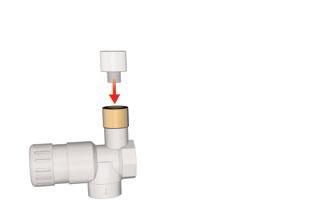
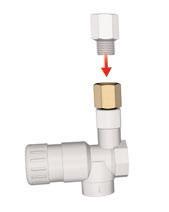
14 NSTALLATN PACKAGE CNTTS The appliances are delivered tested and packaged on a wooden support, protected by anti-shock corner pieces and wrapped in a plastic film. At product reception and after removal of packaging, check the package contents and that the appliance is free of damages. Contents A N boiler nstallation, operation and maintenance instructions A hydraulic kit, comprised of: - A primary safety valve Ø 1/2" F - A reducer Ø 1/4" F - Ø 1/8" M - A check-valve Ø 1/4" F - Ø 1/4" M - A draining valve Ø 1/2" M LER PREPARATN 2 x 664Y


15 NSTALLATN 2 x Y5400
16 NSTALLATN DHW CNNECTN EXAMPLE F PARALLEL CNNECTN Recommended for applications with a high constant flow. The DHW tank must be pressurized before putting the primary circuit (heating) under pressure. The boiler can be connected directly to the DHW circuit. Flush the system before connecting the domestic hot water circuit. The installation must be fitted with an approved safety group, comprised of a 7 bar safety valve, a check valve and a shut-off valve. During the heating process, the domestic hot water expands and the pressure increases. As soon as the pressure exceeds the safety valve setting, the valve opens and discharges a small quantity of water. Using a hot water expansion vessel (2 liters at least) will prevent this phenomenon and reduce the water hammer effect. The hot water output may reach temperatures in excess of 60 C, which can cause burns. ACV therefore recommends that you install a thermostatic mixing valve immediately after the appliance outlet. f stop valves are used in the domestic hot water system, they can cause pressure changes when closed. Use devices designed to reduce water hammer effect to avoid this phenomenon Cold water supply valve 2. Check valve 3. Pressure reducing valve 4. Domestic hot water safety valve set at 7 bar 5. DHW circuit expansion vessel 6. DHW secondary pump (if fitted) 7. Thermostatic mixing valve 8. Draw-off tap 9. Draining valve 10. Stop valve for cleaning 11. Temperature relief valve (UK only) EXAMPLE F SERES CNNECTN Preferable for high-temperature applications with up to 3 units EXAMPLE F HEATNG + STRAGE CNNECTN Recommended for applications requiring a high peak flow. 664Y
17 NSTALLATN HEATNG CNNECTN The DHW tank must be pressurized before putting the primary circuit (heating) under pressure. WARNNG The primary safety valve is supplied with a plastic tube connected to discharge outlet - this is for test purposes only and should be removed. The safety valve should be connected to the sewer using a metallic pipe, e.g. copper. Two couplings are installed at the back of the, that can be used to connect a central heating circuit. Connecting a heating system may reduce the domestic hot water performance. EXPANSN VESSEL The 30 N and 60 N are fitted with an 8 liter expansion vessel. The 70 N and 100 N are fitted with two 10 liter expansion vessels. These expansion vessels are sized for hot water operation only. f the heating system is connected to the primary circuit, calculate the expansion capacity necessary for the total volume of the heating system (refer to the technical instructions from a relevant manufacturer of expansion vessels) way mixing valve 2. Heating pump 3. Check valve 4. Heating circuit isolating valves 5. Safety valve set at 3 bar with pressure gauge 6. Expansion vessel 7. Drain valve 8. Primary circuit filling valve 9. Controller 10. Contact sensor 11. Room thermostat 12. utdoor temperature sensor Y5400
18 STARTNG UP FLLNG THE DMESTC HT WATER AND HEATNG CRCUTS MPRTANT efore pressurizing the central heating circuit, you should first put the domestic hot water tank under pressure. FLLNG THE DMESTC HT WATER CRCUT 1. pen the filling valve (1) and the drawoff tap (2). 2. When water flows out of the tap, the hot water tank is full and the drawoff tap (2) should be closed. PRELMNARY FLLNG F THE HEATNG CRCUT 1. pen the stop valves (A). 2. Make sure that the draining valve (D) is fully closed. 3. pen the filling valves ( and C) to start filling the primary circuit with mains water until you reach an approximate pressure of 1,5 bar in the system. 4. leed the boiler and the whole system using the automatic air bleed valve located on top of the appliance. 1 C A STARTNG UP THE LER STARTNG THE URNER 1. Set the boiler master switch on N and the summer/winter switch on the. symbol. 2. Rotate the boiler control thermostat clockwise to generate a heat demand. 3. Possibly increase the set temperature of the room thermostat, if installed. ADJUSTNG THE CMUSTN 1. Refer to the starting up instructions detailed in the technical manual of the burner. 2. Adjust C 2 as described in the Starting up paragraph of the burner. 3. Check temperatures and C level. LEEDNG THE HEATNG CRCUT 1. leed the heating circuit again to restore a 1.5 bar pressure. 2. Repeat the sequence until complete evacuation of the air contained in the circuit. A D 2 664Y
19 MANTANCE ANNUAL MANTANCE ACV recommends the boilers should be serviced at least once a year. Maintenance and the burner control must be performed by a qualified engineer. More frequent servicing may be required depending on boiler use. f this is the case, consult your installer for advice LER MANTANCE 1. Put the master switch on the control panel on "FF" and isolate power supply to the unit. 2. Turn off the gas or oil supply to the boiler. 3. Remove the flue pipe to gain access to the top of the boiler 4. Remove the casing top panel and lift off the flue reduction collar by releasing the fastening bolts. 5. Remove the turbulators from the flue pipes for cleaning. 6. Unscrew the burner chamber plate and remove the burner 7. rush the flue pipes. 8. Clean the burner chamber and the burner. 9. Reassemble turbulators, flue reduction collar and flue pipe, checking that the gasket of the flue reduction collar is in good condition. Replace gasket if necessary. MANTANCE F THE SAFETY DEVCES - Check that all thermostats and safety devices are working properly. - Test the safety valves on the central heating and hot water circuits. SERVCNG THE URNER For all burners, please refer to the relevant servicing and troubleshooting instructions in the technical manual of your burner. DRANNG THE LER Water flowing out of the drain valve may be extremely hot and could cause severe scalding. Keep people away from discharge of hot water. DRANNG THE HEATNG CRCUT 1. Put the master switch of the control panel on FF, isolate the external electrical supply and turn off the gas or oil supply to the boiler. 2. Close the isolating valves (4) or put manually the 4-way mixing valve (1) on Connect a hose to the draining valve (7). 4. pen the draining valve to empty the primary circuit. DRANNG THE DHW CRCUT 1. Put the master switch of the control panel on FF, isolate the external electrical supply and turn off the gas or oil supply to the boiler. 2. Release the pressure in the heating circuit until the pressure gauge indicates 0 bar. 3. Close valves (1) and (8). 4. pen valves (9) and (10) (first 9 then 10). 5. Allow the drained water to flow into the sewer. For the circuit to be drained, the draining valve (9) must be located at ground level Y5400
20 664Y
21 21 664Y5400
22 664Y
23 23 664Y5400
24
25
26
INSTALLATION, OPERATION AND MAINTENANCE INSTRUCTIONS
 NSTALLATN, PERATN AND MANTANCE NSTRUCTNS HeatMaster 00 N 00 F HeatMaster 00 N / 00 F : 664Y6300 TALE F CNTTS WARNNGS 3 Who should read these nstructions 3 Symbols 3 Warnings 3 Recommendations 3 USER S
INSTALLATION, OPERATING AND SERVICING INSTRUCTIONS BG 2000-S (V13) RU PL DE IT ES NL EN 1 662Y0600 A
 RU PL DE IT ES NL EN 1 662Y0600 A") INSTALLATION, OPERATING AND SERVICING INSTRUCTIONS G 2000-S 25-35 - 45-55 60-70 - 100 (V13) 1 Index WARNINGS GAS FLOW RATE DIMSIONS SETTINGS PARAMETERS SERVICING THE URNER 3 8 13 OPERATING DESCRIPTION
INSTALLATION, OPERATING AND SERVICING INSTRUCTIONS G 2000-S 25-35 - 45-55 60-70 - 100 (V13) 1 Index WARNINGS GAS FLOW RATE DIMSIONS SETTINGS PARAMETERS SERVICING THE URNER 3 8 13 OPERATING DESCRIPTION
INSTALLATION, OPERATION AND MAINTENANCE INSTRUCTIONS
 INSTALLATION, OPEATION AND MAINTANCE INSTUCTIONS HeatMaster 71 101 201 1 664Y6100 TALE OF CONTTS WANINS 3 Who should read these Instructions 3 Symbols 3 ecommendations 3 Warnings 3 USE UIDE 4 Use of the
HeatMaster. Installation, operating and servicing instructions. HeatMaster 71 HeatMaster 101 HeatMaster 201 ENGLISH FRANCAIS NEDERLANDS ESPAÑOL
 HeatMaster ENGLISH Installation, operating and servicing instructions HeatMaster 71 HeatMaster 101 HeatMaster 201 664Y2500. EN 1 ENGLISH INDEX IMPORTANT NOTES 3 Who should read these instructions 3 Symbols
Installation, Operating and Servicing Instructions
 EN 0 / 0 / 00 / 800 Installation, Operating and Servicing Instructions excellence in hot water EN Y000.D EN INDEX Warnings Who should read these instructions Symbols Recommendations Applicable standards
Installation, Operating and Servicing Instructions
 ENGLISH 0 / 0 / 0 / 0 / 00 Installation, Operating and Servicing Instructions FRANCAIS NEDERLANDS ESPAÑOL Y000.A EN ESPAÑOL NEDERLANDS FRANCAIS ENGLISH INDEX WARNING Who should read these instructions
INSTALLATION, OPERATION AND MAINTENANCE INSTRUCTIONS, for the User and the Installer. SMART Line. Smart ME A Y2000 B
 INSTALLATION, OPERATION AND MAINTENANCE INSTCTIONS, for the User and the Installer SMART Line Smart ME 00-300 - 400-600 - 800 A00859-66Y000 B TABLE OF CONTENTS GENERAL RECOMMENDATIONS...4 PRODUCT INFORMATION...5
SMART Line Smart E
 INSTALLATION, OPERATION AND MAINTENANCE INSTCTIONS, for the User and the Installer SMART Line 30-60 - 20-240 - 300 Plus 20-240 - 300 A002858-66Y200 B TABLE OF CONTENTS GENERAL RECOMMENDATIONS...4 PRODUCT
INSTALLATION, OPERATION AND MAINTENANCE INSTRUCTIONS,
 EN INSTALLATION, OPERATION AND MAINTENANCE INSTCTIONS, for the User and the Installer HR i 320-600 - 800 A1002237-661Y1300 B EN EN TABLE OF CONTENTS GENERAL RECOMMENDATIONS...3 PRODUCT INFORMATION...4
INSTALLATION, OPERATION AND MAINTENANCE INSTRUCTIONS,
 INSTALLATION, OPERATION AND MAINTENANCE INSTCTIONS, for the User and the Installer EN SMART Line SL 320-420 - 420 Duplex - 600 A002875-66Y300 A EN TABLE OF CONTENTS GENERAL RECOMMENDATIONS...4 Energy labelling...
Installation, operating and servicing instructions
 English 57-115 - 144-1 - 259 Installation, operating and servicing instructions ITALIA EN 1 ITALIA English INDEX WARnINGS 3 Who should read these instructions 3 Symbols 3 Recommendations 3 Importants notes
INSTALLATION, OPERATION AND MAINTENANCE INSTRUCTIONS BNE 1 - BNE 2 664Y6000 D
 INSTALLATION, OPERATION AND MAINTANCE INSTRUCTIONS BNE 1 - BNE 2 664Y6000 D Addendum - Additional Safety Instructions for Appliances APPLICABILITY : 664Y5000 - Rev C - N2 Condens, Installation, Operation
Installation, operation and maintenance instructions. HRi Y1300-A
 Installation, operation and maintance instructions HRi 321-601 - 800 Table of contts Geral Recommdations...4 User's Guide...5 Control Panel... 5 Appliance Description...6 Models - HRi 321 601-800... 6
INSTALLATION, OPERATION AND MAINTENANCE INSTRUCTIONS,
 INSTALLATION, OPERATION AND MAINTENANCE INSTCTIONS, for the User and the Installer SMART GREEN 130-160 - 210 A1002064-661Y3000 B TABLE OF CONTENTS GENERAL RECOMMENDATIONS...4 PRODUCT INFORMATION...5 Energy
Installation, operating and maintenance instructions
 English Prestige50-75 - 120 MCA-5 Installation, operating and maintenance instructions EN 1 English INDEX Important notes 3 Who should read these instructions 3 Symbols 3 Recommendations 3 Certification
O. Gas boiler. Gaz 6000 W WBN H-E-N/L-S2400. Operating instructions for the end customer (2017/09) en
 en") 8 716 473 216-00.3O Gas boiler WBN 6000-30-H-E-N/L-S2400 Operating instructions for the end customer en 2 Contents Contents 1 Key to symbols and safety instructions................... 2 1.1 Key to symbols..................................
8 716 473 216-00.3O Gas boiler WBN 6000-30-H-E-N/L-S2400 Operating instructions for the end customer en 2 Contents Contents 1 Key to symbols and safety instructions................... 2 1.1 Key to symbols..................................
HeatMaster. Assembling and installation instructions. 201 Booster. HeatMaster. HeatMaster. 200N (Gas) Booster ENGLISH FRANCAIS NEDERLANDS ESPAÑOL
 Booster ENGLISH FRANCAIS NEDERLANDS ESPAÑOL") Heataster Assembling and installation instructions Heataster 201 Booster Heataster 200N (Gas) Booster EN 1 WANINGS 3 Who should read these instructions 3 Symbols 2 Applicable standards 2 ecommendations
Heataster Assembling and installation instructions Heataster 201 Booster Heataster 200N (Gas) Booster EN 1 WANINGS 3 Who should read these instructions 3 Symbols 2 Applicable standards 2 ecommendations
Installation, Operating and Servicing Instructions
 ENGLISH Installation, Operating and Servicing Instructions EN 1 ENGLISH INDEX WARNINGS 3 Who should read these instructions 3 Symbols 3 Recommendations 3 Applicable standards 3 Warnings 3 INTRODUCTION
WHE 2.24 / WHE 2.24 FF
 EN Wall-hung gas boilers WHE 2.24 WHE 2.24 FF User Guide 300011777-001-C . Contents 1 Introduction.............................................................................3 1.1 Symbols used...........................................................................................3
Operating instructions
 Operating instructions Capriz 2 24c 28c GB, IE Contents Contents 1 Safety... 3 1.1 Action-related warnings... 3 1.2 Intended use... 3 1.3 General safety information... 4 2 Notes on the documentation...
Remeha. Fuel oil/gas boilers P 520. Installation and Service Manual A
 Remeha Fuel oil/gas boilers EN Installation and Service Manual 300016859-001-A 63115 Declaration of conformity The appliance complies with the standard model described in declaration of compliance. It
Operating instructions
 The energy you need Operating instructions Betacom 3 24c -A (H-GB) 30c -A (H-GB) GB, IE Contents Contents 1 Safety... 3 1.1 Action-related warnings... 3 1.2 Intended use... 3 1.3 General safety information...
Operating instructions
 Operating instructions For the operator Operating instructions HOME SYSTEM GB, IE Publisher/manufacturer Vaillant GmbH Berghauser Str. 40 D-42859 Remscheid Tel. +49 21 91 18 0 Fax +49 21 91 18 28 10 info@vaillant.de
PrestigeMK2. Installation, Operating and Servicing Instructions. Prestige Solo Prestige AquaSpeed Prestige Excellence ENGLISH
 ENGLISH PrestigeMK2 Installation, Operating and Servicing Instructions Prestige Solo 24-32 Prestige AquaSpeed 24-32 Prestige Excellence 24-32 EN 1 ENGLISH INDEX WARNING 3 Who should read these instructions
INSTALLATION, OPERATION AND MAINTENANCE INSTRUCTIONS,
 INSTALLATION, OPERATION AND MAINTENANCE INSTCTIONS, for the User and the Installer SMART Line SL 320-420 - 420 Duplex - 600 A1004777-661Y3100 B TABLE OF CONTENTS GENERAL RECOMMENDATIONS...4 Energy labelling...
INSTALLATION, OPERATION AND MAINTENANCE INSTRUCTIONS. HeatMaster TC 664Y6800 A
 INSTALLATION, OPERATION AND MAINTENANCE INSTCTIONS HeatMaster 25-35 - 45-70 - 85-120 TC 664Y6800 A TALE OF CONTENTS GENERAL RECOMMENDATIONS...4 USER'S GUI...5 Instructions for the d user... 5 Periodic
Aqua Balance. User s Information Manual. WMB-155C Wall Mount Gas-Fired Combination Boiler Heating and Domestic Hot Water
 Aqua Balance WMB-155C Wall Mount Gas-Fired Combination Boiler Heating and Domestic Hot Water User s Information Manual * Low Lead Content If the information in this manual is not followed exactly, a fire
INSTALLATION, OPERATION AND MAINTENANCE INSTRUCTIONS
 INSTALLATION, OPERATION AND MAINTANCE INSTCTIONS BNE 2 Conds 21.8 kw 664Y5900 D TABLE OF CONTTS GERAL RECOMMDATIONS...4 USER'S GUI...5 Instructions for the d-user... 5 Periodic checks... 5 APIANCE DCRIPTION...6
HeatMaster 25 C. Installation, operating and maintenance. excellence in hot water 664Y4500 E
 HeatMaster 25 C English Installation, operating and maintenance instructions excellence in hot water INDEX Important notes 4 ho should read these instructions 4 Symbols 4 Recommendations 4 Certification
Prestige. Prestige Solo Prestige AquaSpeed Prestige Excellence Installation, Operating and Servicing Instructions
 Prestige Installation, Operating and Servicing Instructions Prestige Solo 24 32 Prestige AquaSpeed 24 32 Prestige Excellence 24 32 excellence in hot water 05/11/23 664123 INDEX INTRODUCTION 2 INSPECTION
Operating instructions
 Operating instructions Gas condensing boiler WARNING: If the information in this manual is not followed exactly, a fire or explosion may result causing property damage, personal injury or loss of life.
User Manual FLOWMAX-90. for model. Condensing water heater 85,000 BTU. Installation, operating, commissioning and maintenance instructions.
 User Manual for model FLOWMAX-90 Condensing water heater 85,000 BTU WARNING If the information in these instructions is not followed exactly, a fire or explosion may result, causing property damage, personal
T UNI 7000 F. Operating instructions For the user (2006/05) AU/GB
 AU/GB") 6 720 648 662-00.1T UNI 7000 F Operating instructions For the user AU/G 2 Contents Contents Contents 2 1 Safety information and explanation of symbols 3 1.1 For your safety 3 1.2 Explanation of symbols
6 720 648 662-00.1T UNI 7000 F Operating instructions For the user AU/G 2 Contents Contents Contents 2 1 Safety information and explanation of symbols 3 1.1 For your safety 3 1.2 Explanation of symbols
Operating Instructions
 Operating Instructions Low Emissions and High Efficiency Condensing Oil Boiler DANGER! If these instructions are not followed exactly, a fire or explosion may be caused with serious property damage or
A/23 MFFI - A/27 MFFI
 A/23 MFFI - A/27 MFFI G.C.N. 47-6-0 / 47-6-2 Servicing Instructions Type C Boilers LEAVE THESE INSTRUCTIONS ADJACENT TO THE GAS METER TABLE OF CONTENTS Page No.. SERVICING INSTRUCTIONS. Replacement of
Installation, operating and. Comfort
 EN Installation, operating and servicing instructions Comfort 00-0 - 60-20 - 20 TABLE OF CONTENTS EN GENERAL Notes Certification CE Standards Packaging SAFETY PRECAUTIONS 5 Symbols used 5 Recommdations
ProCon Streamline Gas Condensing Boiler. Installation and Operating Manual.
 1 MHG Heating Ltd ProCon Streamline Gas Condensing Boiler. Installation and Operating Manual. Unit 4 Epsom Downs Metro Centre, Waterfield, Tadworth, Surrey, KT20 5LR Telephone 08456 448802 Fax 08456 448803
Installation, operation and care. Pellmax UB. Burner not included Replaces:
 Installation, operation and care Burner not included 2011-11-11 ver: Replaces: Contents 11.11 otes...3 General...4 Function...4 Technical data...5 System principle Pellmax with radiator and tank-in-tank
HG 675 CX 60 HG 675 CN 60 HG 675 CW 60
 HG 675 X 60 HG 675 CX 60 HG 675 CN 60 HG 675 CW 60 1 2 1. : 93/68: 90/396: 2006/95/CE: 2004/108/CE: - 1935/2004:. 2002/95/CE: RoHS 2.,.,,,,...,. (,..)..,,.,. ( ),,, ;,,.,.....,.,,,,,,...,. (..),,.,..,.,,,,
Installation and maintenance instructions
 6304 4995 0/004 GB For installer Installation and maintenance instructions Flue gas heat exchanger WT50/60 Please read thoroughly prior to installation and maintenance. Summary About this manual This equipment
/2010 US/CA
 6 720 646 148-11/2010 US/CA (en) For the user User s Instructions Condensing gas boiler Logamax plus GB162-L.B. 80 kw/100 kw Please read thoroughly before operating This manual is available in the English
SERVICE MANUAL RIVA COMPACT M90E.24S M90E.28S M90E.32S Wall hung, fan flue, room sealed gas boiler
 Wall hung, fan flue, room sealed gas boiler SERVICE MNUL RIV COMPCT Models: G.C. ppl. No. M90E.24S 47--970--17 M90E.28S 47--970--18 M90E.32S 47--970--21 Leave this manual adjacent to the gas meter iasi
USERS MANUAL FOR GAS BOILERS
 USERS MANUAL FOR GAS BOILERS PLEASE READ THE MANUAL CAREFULLY: IT CONTAINS IMPORTANT INFORMATION REGARDING SAFETY, INSTALLATION, USE AND MAINTENANCE OF THE APPLIANCE MODELS: NOVADENS 24 NOVADENS 24C NOVADENS
Operating instructions
 Operating instructions Gas-fired condensing boiler Logano plus GB312 For the user Please read carefully before use 7 747 009 296-01/2007 EN Contents 1 For your safety..............................................
SIME FORMAT WALL HUNG BOILERS MODEL 34i AND MODEL 34e. cod A
 cod. 6272262A GENERAL DATA Heating Data Heat Output Input (Adjustable) (Adjustable) Format 34i 11.2 34KW 45 145MJ/hr Format 34e 11.2 34KW 45 145MJ/hr General Specifications FORMAT 34i 34e Main burner injectors
Installation and maintenance instructions
 Technology serving Mankind Installation and maintenance instructions ComfortLine FunctionLine Steel boilers up to 63 kw Wolf GmbH Postfach 1380 84048 Mainburg Tel. +49 8751/74-0 Fax +49 8751/741600 Internet:
Condensing, pre-mixed, wall-hung gas boilers with water tank
 C 271-01 made in Italy Nias condensing Condensing, pre-mixed, wall-hung gas boilers with water tank Life-enhancing heat GB Condensing, pre-mixed, wall-hung boilers with water tank Nias CONDENSING HIGH
PrestigeMK2. Installation, Operating and Servicing Instructions. Prestige Solo Prestige Excellence ENGLISH FRANCAIS NEDERLANDS ITALIANO
 PrestigeMK2 Installation, Operating and Servicing Instructions Serial number higher than 40000: please see the new MCBA parameters in "Instruction for specialist MCBA-5" Prestige Solo 24-32 Prestige Excellence
2.1 BOILER ROOM BOILER ROOM DIMENSIONS 2.3 CONNECTING UP SYSTEM 2.4 CONNECTING UP FLUE 2.5 ELECTRICAL CONNECTION
 FONDERIE SIME S.p.A. of Via Garbo 27 - Legnago (VR) - Italy declares that its diesel-burning boilers are produced in accordance with the requirements of article 3 paragraph 3 of Directive PED 97/23/EEC
Residential Gas Condensing Boiler Greenstar ZBR16/21/28/35/42-3A... ZWB28/35/42-3A...
 70 80 99-00-O Residential Gas Condensing Boiler ZBR//8/35/4-3A... ZWB8/35/4-3A... 70 80 993 (03/03) CA/US Operating Instructions Contents Contents Key to symbols and safety instructions............................
1 VICTRIX ZEUS Superior kw I features
 Wall-hung condensing VICTRIX ZEUS Superior kw I is the new range of wall-hung condensing boilers with 54 litre stainless steel storage tank available in two versions with nominal heat output of 26 kw and
User s Information Manual
 User s Information Manual Gas-Fired Water Boilers With or without Aqua Logic (CWH) Now available Matching High Performance Companion Water Heater (Unit sold separately) If the information in this manual
Hamworthy. Dorchester DR-SA & DR-SE Fully Automatic and Permanent Pilot Direct Gas-Fired Storage Water Heaters. Exceeds Minimum Requirements
 Exceeds Minimum Requirements Hamworthy Dorchester DR-SA & DR-SE Fully Automatic and Permanent Pilot Direct Gas-Fired Storage Water Heaters 18.9 kw to 20.1 kw, Natural Gas or LPG Continuous outputs 369
CROWN WATER HEATERS CPU10 - CPU15 CPOS10 - CPOS15
 CROWN WATER HEATERS CPU10 - CPU15 CPOS10 - CPOS15 COMPACT PLUS 10 and 15 Litre Unvented Under and Over Sink Water Heater INSTALLATION AND USER GUIDE 1 DIMENSIONS 10L - 250mm 15L - 310mm 100mm 80mm 410mm
VIESMANN. Operating instructions VITODENS 050-W. for the system user. With constant temperature or weather-compensated control unit
 Operating instructions for the system user VIESMANN With constant temperature or weather-compensated control unit VITODENS 050-W 9/2014 Please keep safe. Safety instructions For your safety Please follow
Installer manual AG-AA10. Air/air heat pump IHB GB AG-AA10-30 AG-AA10-40/50
 -30 Installer manual Air/air heat pump -40/50 IHB GB 1516-1 331554 Table of Contents 1 Important information 2 5 Installation 7 Safety information 2 Model combinations 7 Read before starting the installation
Oil filled Radiators - Models : OFX750/1000/1500 & OFX750TI/1000TI/1500TI
 FX 50T FX 50 il filled Radiators - Models : FX50/00/500 & FX50T/00T/500T NDXUK0RG (UK) ssue 3 The product complies with the European Safety Standards EN60335-2-30 and the European Standard Electromagnetic
BOILING UNIT REDITAP. Installation and User Guide. IMPORTANT: This booklet should be left with the user after installation and demonstration
 in tap Boiling water to in tap sink Drain Valve (as high as possible) REDITAP CONNECTION SUMMARY Amp mains supply cold mains water into in tap optional filter cold water in hot water BOILING UNIT Installation
Servicing Instructions Type C Boilers G.C.N: LEAVE THESE INSTRUCTIONS ADJACENT TO THE GAS METER
 Servicing Instructions Type C Boilers G.C.N: 4-6-0 47-6-08 47-6-09 47-6-3 LEAVE THESE INSTRUCTIONS ADJACENT TO THE GAS METER TABLE OF CONTENTS Page No.. SERVICING INSTRUCTIONS. Replacement of Parts 3.2
Mikrofill Ethos Condensing combination boiler. Maintenance Instructions 24cc
 Mikrofill Ethos Condensing combination boiler Maintenance Instructions 24cc IMPORTANT Benchmark Installation, Commissioning and Service Record Log Book is enclosed in your customer information pack. This
INSTALLATION, OPERATION AND MAINTENANCE INSTRUCTIONS, for the User and the Installer. SMART Line. Smart ME A Y2000 C
 INSTALLATION, OPERATION AND MAINTANCE INSTCTIONS, for the User and the Installer SMART Line Smart ME 00-300 - 400-600 - 800 A1003499-661Y000 C TABLE OF CONTTS GERAL RECOMMDATIONS...4 PRODUCT INFORMATION...5
DTG Eco / V130
 ECODENS Gas fired condensing boiler EN User Guide 300010111-001-B Contents 1 Introduction.............................................................................3 1.1 Symbols and abbreviations................................................................................3
PRODUCT GUIDE 2018/19 ACV HEATING AND HOT WATER SPECIALISTS
 PRODUCT GUIDE 2018/19 ACV HEATING AND HOT WATER SPECIALISTS CUSTOMER SERVICE INFORMATION Telephone 01383 820 100 Commercial Enquiries uk.sales@acv.com Technical Enquiries uk.technical@acv.com WHO IS MY
VICTRIX 90 VICTRIX 115 Wall-hung condensing boilers for high power
 VICTRIX 90 VICTRIX 115 Wall-hung condensing boilers for high power VICTRIX 90 is the new wall-hung condensing boiler for room heating only, set-up for independent functioning and for that in cascade mode
User and maintenance manual
 GB User and maintenance manual IMPORTANT SAFETY INSTRUCTIONS These instructions shall also be available on website: docs.whirlpool.eu. YOUR SAFETY AND THAT OF OTHERS IS HIGHLY IMPORTANT. This manual and
User Guide Compact-7 series
 User Guide Compact-7 series Boiler-CH Calorifier Combi Introductory remarks Congratulations on the purchase of your Kabola Compact 7. Kabola has been a manufacturer of oil-fired heating systems since 1947.
C Tahiti. condensing
 C 227-01 m a d e i n I ta ly Tahiti condensing Condensing, pre-mixed, wall-hung boilers KC 24 KC 28 - KC 32 indoor, instantaneous, combination boilers KR 24 KR 38 - KR 32 indoor, central heating only boilers
GOLD. User s Information Manual. Water Boiler Series 4
 GV Water Boiler Series 4 User s Information Manual If the information in this manual is not followed exactly, a fire or explosion may result, causing property damage, personal injury or loss of life. Do
GB24 & GB30. User Manual
 GB24 & GB30 User Manual BOILER OUTPUT To Domestic Hot Water:To Central Heating: GB24/30 Minimum 8.0 kw (27,296 Btu/h) GB24 Maximum 24.2 kw (82,570 Btu/h) GB30 Maximum 30.3 kw (103,384 Btu/h) GB24/30 Minimum
USER GUIDE. IMAX XTRA EL kW. For Installation Guide see reverse of book
 USER GUIDE IMAX XTRA EL 320-620kW For Installation Guide see reverse of book When replacing any part on this appliance, use only spare parts that you can be assured conform to the safety and performance
PLEASE LEAVE THIS MANUAL WITH THE OSO UNIT AFTER INSTALLATION INSTALLATION MANUAL
 PLEASE LEAVE THIS MANUAL WITH THE OSO UNIT AFTER INSTALLATION 0 RD 0 RI 0000-06 IM/ IM/a INSTALLATION MANUAL This manual gives detailed advice for installation and should be read carefully prior to fitting
VIESMANN. Operating instructions VITODENS 100. for system users. Heating system with control unit for constant temperature operation
 Operating instructions for system users VIESMANN Heating system with control unit for constant temperature operation VITODENS 100 2/2005 Please keep safe Safety instructions For your safety Please follow
User s Information Manual
 User s Information Manual Series 3 Models 550 and 750 MBH Commercial Condensing Gas-fired water boilers If the information in this manual is not followed exactly, a fire or explosion may result, causing
Installation and maintenance instructions
 6304 4994 03/2006 GB For installer Installation and maintenance instructions Flue gas heat exchanger WT30/40 Please read thoroughly prior to installation and maintenance. Contents Contents Contents 2 1
Stainless Steel Chimney Extractor
 Stainless Steel Chimney Extractor User & Installation Guide LAM2404 LAMONA Appliances Dear Customer, Congratulations on your choice of a LAMONA domestic appliance which has been designed to give you excellent
PLEASE LEAVE THIS MANUAL WITH THE OSO UNIT AFTER INSTALLATION INSTALLATION MANUAL
 PLEASE LEAVE THIS MANUAL WITH THE OSO UNIT AFTER INSTALLATION SOLARCYL IM/SC INSTALLATION MANUAL This manual gives detailed advice for installation and should be read carefully prior to fitting any unvented
VIESMANN. Operating instructions VITODENS 100-W. for the system user
 Operating instructions for the system user VIESMANN Heating system with control unit for constant temperature or weather-compensated mode VITODENS 100-W 1/2012 Please keep safe. Safety instructions For
MCR 24 MCR 24/28 MI MCR 30/35 MI MCR 34/39 MI
 Vivadens EN Wall-hung gas condensing boilers MCR 24 MCR 24/28 MI MCR 30/35 MI MCR 34/39 MI User Guide 300015874-001-B Contents 1 Introduction...4 1.1 Used symbols...4 1.2 Abbreviations...4 1.3 General...4
British Gas 330+ High Efficiency Condensing Boiler. Instructions for Use. To b e l e f t w i t h t h e u s e r. British Gas Service Tel:
 0020051423-02 10.07 British Gas 330+ High Efficiency Condensing Boiler Instructions for Use To b e l e f t w i t h t h e u s e r British Gas Service Tel: 0845 9500400 WARNING GAS LEAK OR FAULT Turn off
Conversion Instructions Logano G234X. Gas boiler. Please read carefully before installing and servicing. Gas boiler
 Gas boiler UPON COMPLETION OF THE INSTALLATION THE INSTALLER MUST INSTRUCT THE OWNER AND OPERATOR ON THE FUNCTIONALITY AND THE PROPER OPERATION OF THE BOILER AND THE HEATING SYSTEM. INSTALLER MUST REVIEW
User s Information Manual
 User s Information Manual Series 2 Models 1000-2000 MBH Commercial Condensing Gas-fired water boilers If the information in this manual is not followed exactly, a fire or explosion may result, causing
Proline GAS HOB Model TCG40IX Instruction Book
 Proline GAS HOB Model TCG40IX Instruction Book GB Operating and Installation Instructions Index Technical data and specifications...... 3 Installation...................... 3-6 Ventilation........................
INSTALLATION AND OPERATING INSTRUCTIONS GN2. HIGH EFFICIENCY CAST IRON BOILER FOR LIQUID and/or GAS FUELS
 INSTALLATION AND OPERATING INSTRUCTIONS HIGH EFFICIENCY CAST IRON BOILER FOR LIQUID and/or GAS FUELS INDEX 1. Technical information... page 3 2. Dimensional and technical characteristics... page 3 3. Packing
 80-140 80-180 95-260 70-360 65-400 65-500 Installation User and Service Manual TM your installer TM Warning Read this manual carefully before first using the water heater. Failure to read this manual and
Operating instructions
 Operating instructions For the operator Operating instructions ecotec plus Gas-fired wall-hung high-efficiency boiler GB, IE Publisher/manufacturer Vaillant GmbH Berghauser Str. 40 D-42859 Remscheid Telefon
PHRIE / PHIE InvERTER monoblock air To water HEaT PumP medium TEmPERaTuRE
 TEcHnIcal InsTRucTIons PHRIE / PHIE InvERTER monoblock air To water HEaT PumP medium TEmPERaTuRE PHRIE 095 PHRIE 1 PHIE 095 PHIE 1 PHRIE 155 PHRIE 157 PHRIE 175 PHRIE 177 PHRIE 195 PHRIE 197 PHRIE 7 PHRIE
VIESMANN. Installation instructions VITOCELL 300-B. for contractors. Vitocell 300-B Type EVBA-A. Dual mode DHW cylinder, 300 and 500 l
 Installation instructions for contractors VIESMANN Vitocell 300-B Type EVBA-A Dual mode DHW cylinder, 300 and 500 l VITOCELL 300-B 1/2017 Dispose after installation. Safety instructions Please follow these
Servicing manual. 600 Series - 11S / 19S / 24S / 24C. Wall-mounted condensing gas boiler. For trade use
 GB122 Servicing manual Wall-mounted condensing gas boiler 600 Series - 11S / 19S / 24S / 24C For trade use Please read thoroughly before attemting to diagnose fault 7217 4900 (03/2010) GB/IE List of contents
Room sealed circuit appliance sold without the terminal or the combustion air supply and exhausted gas ducts. TYPE C 63 TYPE B TYPE B 23
 Room sealed circuit appliance sold without the terminal or the combustion air supply and exhausted gas ducts. TYPE C 63 TYPE B Type B 23 on the wall Ø 80 duct, available in the following lengths: 1000,
Installation, operating and servicing instructions
 09-5 - - 8-6 ENGLISH Single & Tri Phase Installation, operating and servicing instructions FANCAIS NEDELANDS EN ENGLISH FANCAIS WAnINGS Who should read these instructions Symbols ecommendations Applicable
GB User and maintenance manual
 GB User and maintenance manual IMPORTANT SAFETY INSTRUCTIONS These instructions shall also be available on website: docs.whirlpool.eu. YOUR SAFETY AND THAT OF OTHERS IS VERY IMPORTANT This manual and
Servicing manual. Wall-mounted condensing gas boiler 600 Series - 11S / 19S / 24S / 24C /2002 GB(EN) For trade use
 For trade use") GB122 7210 1300-12/2002 GB(EN) For trade use Servicing manual Wall-mounted condensing gas boiler 600 Series - 11S / 19S / 24S / 24C Please read thoroughly before attempting to diagnose fault List of contents
GB122 7210 1300-12/2002 GB(EN) For trade use Servicing manual Wall-mounted condensing gas boiler 600 Series - 11S / 19S / 24S / 24C Please read thoroughly before attempting to diagnose fault List of contents
VICTRIX Superior kw Export VICTRIX Superior kw X Export
 Wall-hung condensing VICTRIX Superior kw is the instantaneous sealed chamber wallhung boiler with power of 32 kw which, thanks to condensation technology, is characterised for its high efficiency and guarantees
HEAT RECOVERY AIR HANDLING UNIT
 HEAT RECOVERY AIR HANDLING UNIT OPERATION MANUAL KOMFORT_L v2(2)_en.indd 1 07.08.2015 15:0:44 CONTENTS Introduction General Safety regulations Transportation and storage regulations Manufacturer's warranty
HT V2 HT Split
 Scroll compressor Refrigerant R07C Aqu@Scop HT V Aqu@Scop HT Split High Temperature Air-to-Water Heat Pumps Models -, -7 and 8-9.0 to 7.9kW Aqu@Scop HT V / Aqu@Scop HT Split Installation examples - Single
INSTALLATION MANUAL. Ecoline Geo RI HP PLEASE LEAVE THIS MANUAL WITH THE OSO UNIT AFTER INSTALLATION
 PLEASE LEAVE THIS MANUAL WITH THE OSO UNIT AFTER INSTALLATION Ecoline Geo RI HP INSTALLATION MANUAL The Ecoline GEO is an indirect unvented cylinder designed and approved for use with a heat pump. The
and Installation Instructions The installation instructions for the Unit pressure jet oil burner is included in the pressure jet oil burner pack.
 Technical Guide and Installation Instructions MKS / MUS Steel boiler 70-550 kw The installation instructions for the Unit pressure jet oil burner is included in the pressure jet oil burner pack. The control
GWC. User s Information Manual. Gas-Fired Water Boilers. Model
 Model GWC Gas-Fired Water Boilers User s Information Manual If the information in this manual is not followed exactly, a fire or explosion may result, causing property damage, personal injury or loss of
High temperature air-to-water heat pumps
 Designed to replace conventional boilers and produce domestic hot water 4 High temperature hot water (+65 C) 4 Winter operation (-20 C) 4 High energy efficiency (CP) 4 Compact and quiet 4 Scroll compressors
INSTALLATION AND OPERATING INSTRUCTIONS KLIMA
 INSTALLATION AND OPERATING INSTRUCTIONS KLIMA - 1 - CONTENTS 1.- PRESENTATION... 2 2.- LIST OF COMPONENTS... 3 3.- CONTROL ELEMENTS... 4 4.- INSTALLATION INSTRUCTIONS... 5 4.1 LOCATION... 5 4.2 FLUE...