INSTALLATION, OPERATION AND MAINTENANCE INSTRUCTIONS
|
|
|
- Beverley Roberta Patterson
- 6 years ago
- Views:
Transcription


1 INSTALLATION, OPERATION AND MAINTANCE INSTCTIONS for the Installer and the User Compact Conds A Y7200 B
2 Adddum - Additional Safety Instructions for Gas Appliances APICABILY : 664Y Rev E - Delta Pro S -Pro Pack, Installation, Operation and Maintance Instructions 664Y Rev B - HeatMaster (V13), Installation, Operation and Maintance Instructions 664Y Rev B - HeatMaster 200N, Installation, Operation and Maintance Instructions 664Y Rev D - Prestige Solo/Excellce, Installation, Operation and Maintance Instructions 664Y Rev D - HeatMaster TC, Installation, Operation and Maintance Instructions 664Y Rev B - HeatMaster 25C, Installation, Operation and Maintance Instructions 664Y Rev B - Compact Conds , Installation, Operation and Maintance Instructions 664Y Rev C - WaterMaster , Installation, Operation and Maintance Instructions Make sure that the appliance is connected to the earth. Veiller à ce que l appareil soit raccordé à la terre. Zorg ervoor dat het toestel is geaard. Asegúrese de que el aparato esté conectado a tierra. Assicurarsi che l apparecchio sia elettricamte collegato alla messa a terra dell impianto. Stell Sie sicher, dass das Gerät geerdet ist. Upewnij się, że urządzie jest uziemione. Убедитесь, что прибор заземлен. Check that the gas type and pressure from the distribution network are compatible with the appliance settings. Vérifier que le type de gaz et la pression du réseau de distribution sont compatibles avec les réglages de l appareil. Controleer of het type gas de druk van het distributietwerk in overestemming zijn met de toestelinstelling. Compruebe que el tipo de gas y la presión de la red de distribución son compatibles con los ajustes del aparato. Controllare che il tipo di gas e la pressione della rete di distribuzione siano compatibili con le impostazioni dell apparecchio. Stell Sie sicher, dass die Gasart und der Druck des Verteilungsnetzes mit d Geräteinstellung kompatibel sind. Sprawdzić, czy typ gazu i ciśniie sieci dystrybucyjnej są zgodne z ustawiiami urządzia. Убедитесь, что тип газа и давление в распределительной сети совместимы с настройками прибора. Adddum Gas Appliances : A ADD0000
3 TABLE OF CONTTS GERAL RECOMMDATIONS...3 Safety Instructions...3 USER S GUI...4 Meaning of Symbols...4 Boiler Marking...5 Control Panel and Display...6 What to Check on a Regular Basis...7 Lockout Scre...7 In case of Problem...7 Boiler Setup Guide for the User...8 User s mu and parameter descriptions...9 INSTALLER S GUI...10 Principles of Operation...10 Geral Heating Circuit Domestic Hot Water preparation (DHW) Safety features...11 Other features...11 Electrical connections...11 Slow start principle...12 Boiler Setup Guide for the Installer...12 Installer s mu and parameter descriptions...13 Integrated Cascade Functionality...16 Geral Cascade operation Split DHW...17 Heterogeous cascade...17 Wiring the cascade chain Wiring procedure Auto-detection Cascade parameters Electrical connections Cascade errors Modbus Supported commands Wiring procedure Electrical connections Configuration parameters MODBUS register map APIANCE DCRIPTION...22 Models - Compact Conds TECHNICAL CHARACTERISTICS...23 Dimsions Electrical Characteristics Compact Conds NTC resistance...24 Wiring Diagram and Electrical Connections...24 Combustion Characteristics Gas Categories Pneumatic Connections...27 Hydraulic Characteristics...27 Hydraulic Pressure Drop Curve of the Boiler...27 Maximum Operating Conditions...27 Recommdations for the prevtion of corrosion and scaling in Heating Systems INSTALLATION...29 Safety Instructions for the Installation Package Contts Tools Required for the Installation Boiler preparation Heating connection Removal and Installation of the Front and Side Panels Chimney Connection...31 Calculation of the Flue Pipe Lgth...32 Gas connection...33 System Configurations...33 Boiler load settings...33 Basic Configuration - Compact Conds: High Temperature Heating Circuit Controlled by Room Thermostat and Optional Outdoor Ssor STARTING UP...35 Safety Instructions for Starting up...35 Tools Required for Starting up...35 Checks before Starting up...35 Starting up the Boiler Checking and Adjusting the Burner MAINTANCE...37 Safety Instructions for the Boiler Maintance...37 Tools Required for Maintance...37 Boiler Shut-down for Maintance...37 Periodic Boiler Maintance Tasks...37 Draining the Heating Circuit of the Boiler Removal, Check and Installation of the Burner Electrodes Removal, Check and Installation of the Burner...39 Cleaning the Exchanger Restarting after Maintance TROUBLHOOTING...41 Errors (hard and soft lockouts)...42 LOCKING COD...43 SERVICE LOG...46 CLARATION OF CONFORMY
4 GERAL RECOMMDATIONS NOTE This manual contains important information with respect to the installation, the starting up and the maintance of the appliance. This manual must be provided to the user, who will read it carefully and keep it in a safe place. We accept no liability should any damage result from the failure to comply with the instructions contained in this technical manual. SAFETY INSTCTIONS If you smell gas: - Immediately isolate the gas supply. - Op windows and doors to vtilate the area. - Do not use any electrical appliances and do not operate any switches. - Immediately notify your gas supplier and/or your installer. Esstial recommdations for safety It is prohibited to carry out any modifications to the appliance without the manufacturer s prior and writt agreemt. The product must be installed by a qualified gineer, in accordance with applicable local standards and regulations. The installation must comply with the instructions contained in this manual and with the standards and regulations applicable to heating systems. Failure to comply with the instructions in this manual could result in personal injury or a risk of vironmtal pollution. The manufacturer declines all liability for any damage caused as a result of incorrect installation or in the evt of the use of appliances or accessories that are not specified by the manufacturer. Esstial recommdations for the correct operation of the appliance In order to sure that the appliance operates correctly, it is esstial to have it serviced by a certified installer or maintance contractor every year. In case of anomaly, please call your service gineer. Faulty parts may only be replaced by guine factory parts. Geral remarks The availability of certain models as well as their accessories may vary according to markets. The manufacturer reserves the right to change the technical characteristics and features of its products without prior notice. In spite of the strict quality standards that ACV applies to its appliances during production, inspection and transport, faults may occur. Please immediately notify your approved installer of any faults. Esstial recommdations for safety Do not store any flammable or corrosive products, paint, solvts, salts, chloride products and other detergt products near the appliance. Make sure that the condsate outlet is never obstructed and that a condsate neutralisation system is installed if required. This appliance is not intded for use by persons (including childr) with reduced physical, ssory or mtal capabilities, or lack of experice and knowledge, unless supervised or unless they have be giv instruction concerning the use of the appliance by a person responsible for their safety. Childr should be supervised to sure that they do not play with the appliance. Geral remarks The d user is only allowed to carry out the basic set-up operations mtioned in "Boiler Setup Guide for the User" on page 8, after he has received all relevant instructions from the installer. Any other set-up must be carried out by an approved installer. If the d user misuses the installer code to access installer-specific parameters and makes changes that cause a system failure, any warranty claim will be void. 3
5 USER S GUI MEANING OF SYMBOLS Symbols on the packaging Meaning Symbols in the manual Meaning Fragile Esstial recommdation for safety (of persons and equipmt) Keep dry Esstial recommdation for electrical safety (electrical hazard) Keep standing, up Esstial recommdation for the correct operation of the appliance or the system Geral remark Danger of tipping over Hand truck or pallet truck required for transport Do not cut packaging to op Do not stack Symbols on the appliance Meaning Heating circuit Domestic Hot Water circuit 4
6 USER S GUI BOILER MARKING Location: At the back of the boiler The part number (Typ) and serial number of the appliance are indicated on its rating plate and must be provided to ACV in case of warranty claim. Failure to do so will make the claim void. SPECIM SPECIM Compact Conds 170 Compact Conds 250 SPECIM SPECIM Compact Conds 210 Compact Conds 300 5

. See the example below.")
. 2.")
7 USER S GUI CONTROL PANEL AND DISAY Home scre : It shows the status of CH and DHW circuits (ON or OFF, as defined by the user/installer in the setup), the activation of the anti-freeze function, the currt temperature, the currt pressure, the operation of the circulation pump, the currt date and time. A flame symbol is also displayed wh the unit is fired. Red keys: Allow to select specific items on the display, as well as increase/decrease the values shown on specific scres (wh associated with + or - symbol on the display) or go back to the previous scre (wh associated with on the display). See the example below. USER TECHNICIAN Press this key to access the User mu Press this key to access the Installer mu Press this key to go back to the previous scre Panel Description 1. Pressure gauge - Indicates the primary circuit pressure (min. 1 bar wh cold). 2. MAXSYS LCD Display - It is the setup interface of the boiler and indicates the parameter values, the error codes and the set-up status of the parameters. It displays a series of scres, each showing information and/or icons. 3. Keypad - to browse through the scres of the MAXSYS controller, set up the boiler, increase and decrease the displayed values and validate the selections and access the User or Installer set-up scres. See detail on the right. 4. ON/OFF master switch of the boiler - To turn the appliance ON and OFF. 5. 5A Fuse - To protect the electrical system of the boiler Tuesday, 16 February :56 Key Function ok esc mu eco To scroll up the mus on the display ok To validate a selection or a value esc mu To scroll down the mus on the display To exit a scre and go back to the Home scre To access the User / Installer mu selection scre To activate the Holiday function TR eco To put the boiler in OFF mode To able/disable the CH and DHW functions To able the ECO function 6
8 USER S GUI WHAT TO CHECK ON A REGULAR BASIS Esstial recommdations for the correct operation of the appliance ACV recommds to check the system at least every 6 months as follows: Check that the system water pressure is at least 1 bar wh cold. If the pressure drops below 0.8 bar, the built-in pressure ssor blocks the appliance until the pressure exceeds 1.2 bar. If it is required to top up the system to maintain the minimum recommded water pressure, always turn the appliance off and only add small amounts of water at a time. If a large amount of cold water is added in a hot boiler, the boiler can be damaged definitively. If the system needs to be refilled repeatedly with water, please contact your installer. Check that there is no water on the floor under the boiler. If there is, please call your installer. If a condsate neutralisation system is installed, check it and have it cleaned regularly. Check regularly that there is no error code (lockout) flashing on the display. Refer to paragraph below. IN CASE OF PROBLEM... Check the list of faults and corresponding codes below to get the solution(s). If no solution is provided here, please contact your installer who will determine the correct solution. Fault code - E1 Problem Possible Cause(s) Solution The appliance does not turn on wh pressing the ON/OFF Master switch Failed ignition No power supply The burner failed to light after 3 ignition attempts Check the power supply and that the appliance power plug is connected to the network. Check gas supply to the boiler. E13 Reset limit reached Resets are limited to 5 every 15 minutes Turn unit OFF and ON to resume normal operation. LOCKOUT SCRE If a problem occurs, the Lockout scre replaces the Home scre. The error is indicated by a code and message on the display. Pressing the OK key will reset the boiler. Using the code on the display, solve the problem with the table on the right, th reset the boiler. If the problem cannot be solved and/or if the code is not provided in this table, please contact your installer. E34 E37 Low voltage Low Water Line voltage has fall below an acceptable operating level Water pressure has fall below an acceptable operating level (0.8 bar) The boiler will automatically reset once line voltage returns to normal. Refill the system to reach a normal range pressure. The boiler will automatically reset once water pressure returns to normal. E94 Internal Display Fault Display memory error Turn appliance off and on to resume normal operation. 7
9 USER S GUI BOILER SETUP GUI FOR THE USER Through the User mu, the following parameters can be set : The main parameters of the Compact Conds boilers can be set up by the user using the user setup function of the controller. It allows the user/installer to quickly setup the appliance for immediate operation according to the system configuration. A more extsive mu is also provided for the Installer, refer to Installer s mu and parameter descriptions on page 14. Accessing the User mu - Press the mu key from the keypad to access the scre shown below Heating Domestic Hot Water Holiday The user can define the CH setpoint, the outside temperature at which the heating must be stopped (Outside air temp. ssor required), the temperature reduction for the Eco mode, and he can schedule the operation of the CH circuit. Wh an external DHW tank is installed in the system, the user can define the DHW setpoint, the temperature reduction for the Eco mode, as well as schedule the operation of the DHW circuit. This mu allows to define the CH and DHW setpoints applicable in holiday mode. Maintance This function provides information related to the maintance operations (contact details and maintance due date). USER Press this key to access the User mu Settings Diagnostics In this mu, various geral settings can be defined, such as language, units, date, time, etc. In the diagnostics, the user can find the boiler usage information as well as the history of errors. TECHNICIAN For a detail of the scres and descriptions of the user s mu, see the diagram on the following page. 1. HEATING 2. DOMTIC HOT WATER 3. HOLIDAY 4. MAINTANCE 5. SETTINGS 6. CHIMNEY SWEEPER 7. DIAGNOSTICS ok to confirm The selection is highlighted. Scroll up and down the mu by pressing the and keys from the keypad. Validate your selection by pressing the OK key from the keypad. 8
10 USER S GUI USER S MU AND PARAMETER DCRIPTIONS HEATING DOMTIC HOT WATER HOLIDAY MAINTANCE SETTINGS 1. CH temperature/otc set 2. Eco setpoint reduction 3. Scheduler set CH setpoint Outside temperature for CH off Enable/disable on-board scheduler Scheduler set The Heating mu (user) allows to: 1. Set the CH temperatures and OTC curve parameters : CH setpoint: to adjust the setpoint of CH circuit. Outside temperature for CH off: to set the external temperature at which heat demand is stopped. If set to OFF, the heat demand will never be stopped by the controller (unless RT is removed, or there is a bridge betwe terminal strip C2: 1, 2). 2. Set the temperature that will be subtracted from actual setpoint if ECO mode is active, using the Eco setpoint reduction. 3. Display the scheduler mu Enable/disable scheduler: to Enable or disable the CH on board scheduler. Scheduler set: to program scheduler according to the days of the week, per day, or per range of days. CHIMNEY SWEEPER DIAGNOSTICS 1. DHW setpoint 2. Eco setpoint reduction 3. Scheduler set Enable/disable on-board scheduler Scheduler set The Domestic Hot Water mu (user) allows to: 1. Set the actual DHW temperature (in case there is a ssor in the DHW circuit) OR set the base boiler flow temperature (in case there is a switch). 2. Set the temperature that will be subtracted from actual setpoint if ECO mode is activated, using the Eco setpoint reduction. 3. Display the scheduler mu Enable/disable scheduler: to Enable or disable the DHW on board scheduler. Scheduler set: to program scheduler according to the days of the week, per day, or per range of days. 1. CH holiday setpoint 2. DHW holiday setpoint 1. Service information 2. Service due date 1. Select language 2. Select units 3. Set date 4. Set time The Holiday mu allows to: 1. Set the CH temperature wh holiday mode is active. 2. Set the DHW temperature wh holiday mode is active. The Maintance mu allows to: 1. Display the service company phone nr. or any other tered information. 2. Show the next service due date. Wh the period is expired, an indication shows on the scre. The Settings mu allows to: 1. Select the language (English, Italian, German or Russian). The currt language is highlighted 2. Select the temperature unit. The currt unit used in the controller is highlighted. 3. Set the date. 4. Set the time, after selecting the time format (24/12 hours). 1. Chimney sweeper 1. Boiler information 2. Lockout history 1. Manual Mode. Pressing OK forces a CH demand that will ignite the boiler, which will operate at % of power (timeout: 15 minutes). While the test is in progress, it is possible to navigate the other mus. The Diagnostics mu allows to: 1. Display the following boiler information: CH request, DHW demand, Firing rate (in %)*, Flame ionization currt (µa)*, boiler setpoint*, boiler supply temperature*, return temperature*, flue temperature*, outdoor temperature*, DHW storage temperature*, boiler fan speed, CH ignitions (number), CH runtime (in hours), DHW ignitions (number), DWH runtime (in hours), system pressure (water pressure in bar/psi), Heat exchanger temp., 0-10V input, Target power (Items with an * at the d will op a graph that shows the latest 120 variable values stored every 12 minutes (24 hours history) wh pushing OK). 2. Display the list of rect errors. Pushing on OK wh the lockout is highlighted will op a scre that contains details on the boiler status wh the error occurred. 9
11 USER S GUI FACTORY SETTINGS USER MU Default Min Max 1 CH temperature/otc set 1 Ch setpoint /Technician 2 Outside temperature for CH off OFF HEATING 2 ECO setpoint reduction Scheduler set 1 Enable/disable on board scheduler Enabled Disabled Enabled 2 Scheduler set ON ON OFF ECO 1 DHW setpoint (Switch) DHW setpoint (NTC ssor) DOMTIC HOT WATER 2 ECO setpoint reduction Scheduler set 1 Enable/disable on board scheduler Enabled Disabled Enabled 2 Scheduler set ON ON OFF ECO 1 CH holiday setpoint /Technician 3 HOLIDAY 2 DHW holiday setpoint (Thermostated) DHW holiday setpoint (NTC ssor) MAINTANCE 1 Service information Service tel. set by Technician 2 Service due date Date set by Technician 1 Select language English English Italian German Russian 5 SETTINGS 2 Select units Celsius Fahrheit Celsius 3 Set date set date 4 Set time 24 hours 24 hours 12 hours 6 CHIMNEY SWEEPER OFF DIAGNOSTICS 1 Boiler information Real time boiler status 2 Lockout history Overview lockout history Status boiler at time of lock/block 10
12 INSTALLER S GUI PRINCI OF OPERATION Geral The Compact Conds is a room sealed boiler, equipped with a cast aluminium heat-exchanger. The boiler is provided with a heating circuit, but no internal Domestic Hot Water production tank. However, an external DHW tank can be installed in the system. Refer to System Configurations on page 35. The CH circuit is not provided with a CH-pump. The installer must therefore install one in the system, whose hydraulic resistance will match the hydraulic resistance of the boiler(s) and system. Please contact your ACV represtative for the correct accessories. The Compact Conds boilers (both CH and DHW circuits) are controlled by the MAXSys processor. Heating Circuit The heating circuit can be controlled using various devices (see also Electrical connections on page 12): On-off room thermostat (standard) - As standard the boiler is programmed to use an on-off room thermostat. The desired flow temperature is adjustable, but as standard is set to 80 C. At CH heat request from the room thermostat (and no DHW heat request prest) the CH-pump is activated after 10 seconds. The controller will adjust the burner-input in such a way that a flow-temperature of 80 C is achieved towards the CH-circuit. 0-10V Control (optional) Optional 0-10V In the Technician mu, advanced CH settings, CH request, either 0-10Vdc % or 0-10Vdc SP can be selected. 0-10Vdc % power control A value betwe 2 and 10Vdc gerates a CH power demand proportional to this value, betwe 0 and 100% (0% = minimum load, 100% = nominal load). The heat demand is cancelled below 1 volt. The setpoint of maximum flow temperature is set to 90 C. In the User/Technician mu, diagnostics, boiler information, the actual voltage input and target power are displayed. 0-10Vdc Setpoint A value betwe 2 and 10Vdc gerates a CH setpoint demand proportional to this value, betwe minimum CH flow temperature and maximum CH flow temperature. The heat demand is cancelled below 1 volt. The minimum and maximum CH flow temperatures can be set in the Technician mu, advanced CH settings, CH temperatures. In the User/Technician mu, diagnostics, boiler information, the actual voltage input and boiler setpoint are displayed. Take care that the 0-10 V DC signal is disturbance free! Outside Temperature Control OTC (optional) The boiler is prepared to work with an outdoor ssor. In the Technician mu, Advanced CH settings, CH request, OTC only must be selected. The outdoor ssor is th automatically detected by the controller. The parameters corresponding with A-E in the figure below can be set in the Technician mu (Advanced CH settings). A B C D E OTC offset: minimum CH setpoint value OTC setpoint maximum: maximum CH setpoint value OTC weather cold: external temperature value at which the maximum CH value will be used. OTC weather warm: external temperature value at which the minimum CH value will be used OTC warm weather shutdown: external temperature value at which the CH demand will d In the User mu, an eco setpoint reduction (night reduction) can be set. A day, week and weekd will also be available (on, eco off) The outdoor ssor can be ordered at your supplier. The ssor should be installed on the north-side of the building at approximately 2 meters high. The resistance of the outdoor NTC should be 12 kohm at 25 C. Digital communication (optional) - The boiler is also prepared for digital communication with room thermostats, using communication protocols like Op-Therm (automatically recognised if correctly connected. Please contact your ACV represtative for more details and the correct accessories. Domestic Hot Water preparation (DHW) External storage tank with thermostat (electric 3-way valve) - As standard, the DHW configuration is set to use storage tank + tank thermostat : For hydraulic connection of an external storage tank to the boiler, one should either use: the default configuration (2 pumps): 230 VAC DHW pump and CH pump an electric 3-way valve with a maximum travel time of 255 sec. At the d of the travel time in either direction DHW or CH, the 230 Vac on the 3-way valve will be switched off. The 2 wires of the tank thermostat need to be connected as indicated in Electrical connections on page
13 INSTALLER S GUI Wh using an electric 3-way valve, adjust the setting in the Technician mu, system settings, boiler parameters, number of pumps to Pump and 3-way valve. The 3-way valve travel time can be changed in the Technician mu, system setting, boiler parameters, 3-way valve travel time. External storage tank with NTC ssor - If the storage tank is equipped with an NTC ssor, adjust the setting in Technician mu, advanced DHW settings, DHW request to Ssor. The resistance of the outdoor NTC should be 12 kohm at 25 C. The 2 wires of the tank NTC ssor need to be connected as indicated in Electrical connections on page 12. Heat request and keeping on temperature of the storage tank is done at an adjustable temperature (default set at 60 C, the flow temperature is DHW setpoint + 20K). In case of a CH heat request, immediately after finishing the heat request for DHW, there is a risk of hot water flowing into the CH system (hot shot). Geral behaviour with external storage tank (DHW priority) Disabling/Enabling warm water operation : press the Summer-Winter button. In the default boiler configuration, meaning 2 pumps (DHW and CH pump), a DHW request has priority over CH request In the Technician mu, Advanced DHW settings, DHW priority, the DHW priority over CH can be disabled or the period after which the DHW priority ds can be defined. The CH circuit can be served for the same amount of time. In case the DHW priority is disabled and both demands are active at the same time, both pumps (CH and DHW) will be activated. During that time, the flow temperature is set to either 80 C (thermostat) or DHW setpoint + 20K (NTC ssor). In some countries, at outputs 40 kw, double separation is required betwe exchanging media. Safety features The Compact Conds features various safety devices to protect the boiler and the complete system: Main fuse (5A), located near the On/Off switch, on the right side of the control panel. Siphon pressure switch, connected to the sump (P1), prevts overflow of the siphon in case the back pressure is too high in the chimney Overheat limit switch (thermostat), set at 105 C. Air pressure switch, connected to the vturi, checks the amount of air (by means of a Δp measuremt) before start. A Frost protection mechanism: This function protects the boiler only, not the system. As soon as the flow temperature drops below 8 C, the ctral heating pump is activated. As soon as the flow temperature is at 6 C, the burner starts up at minimum load until the flow temperature rises to 15 C. The CH-pump will continue to run for 10 minutes. The function can be abled or disabled through the Technican s mu. Wh the frost protection is disabled, only the pump operate. An anti-freeze function is also available using a frost thermostat connected in parallel with the room thermostat. Another possibility is the use of an outdoor ssor in combination with the OTC settings (to be set by the installer). The CH pump will be activated if the outdoor temperature drops below 8 ºC. In order to able the Compact Conds boiler to protect the whole system against freezing, all the valves of the radiators and the convectors should be completely op. Other features Eco working mode - Wh the Eco button (eco) is pressed, a programmable value is substracted from the flow temperature setpoint. The value can be changed through the ECO setpoint reduction in the User mu or the Installer mu. Holiday mode - Wh the Holiday button ( ) is pressed, a request is displayed, asking to ter the start and d dates of the holiday period. It is also possible to set the CH flow and DHW temperatures wished for this period. Manual mode (Chimney Sweeper) - For periodical maintance and/or service, a CH request can be gerated to force the burner (not in error condition) to a specific load, from minimum to nominal (100%). The chimney sweeper can be started from the User mu and will be active for 15 minutes. While active, it is possible to navigate through other mus to check the boiler status and functionality. CH and DHW Schedulers - For CH and DHW, separate schedulers can be set. By default, both schedulers are abled and always on. Scheduler set (ON, ECO, OFF) can be done for each day, for a group of weekdays, for weekd days or for an tire week. The status of the scheduler is set on the main scre (ON, ECO, OFF). The scheduler can be set in the User mu, heating or domestic hot water or in the Technician mu, User settings, Heating or Domestic hot water. Cascade - The boilers can be set up in a cascade configuration, without the used of an external controller. Please refer to Integrated Cascade Functionality on page 18. Modbus - A Modbus controller can also be used to control the boiler(s). Refer to «Modbus» on page 22. Electrical connections To be connected to 0-10 V control Strip C2, pin 3 (negative 0Vdc) and pin 4 (+ positive) Outside Temperature Control (OTC) Digital communication (Op therm) Strip C2, pins 5 and 6 Strip C2, pins 1 and 2 DHW pump Strip C1, pins 6, 7 and 8 CH pump Strip C1, pins 9, 10 and 11 Hydraulic 3-way valve Strip C1, pins 6, 7 and 8 Electric 3-way valve Strip C1, pins 6, 7, 8 and 9 Tank thermostat Strip C2, pins 7 and 8 Tank NTC ssor Strip C2, pins 7 and 8 Cascade Modbus Special Kit (Terminal strip C3 to be installed + cables) Special Kit (Terminal strip C3 to be installed + cables) Remark Shortcut to be installed on terminal C2, betwe pins 1 & 2 Bridge to be installed on terminal C2, betwe pins 1 & 2 (or use them to connect room thermostat on/off) Refer to Integrated Cascade Functionality on page 18 Refer to Modbus on page 22 12
14 INSTALLER S GUI Start up process During heat demand, the pump is activated by the controller. After zero-check of the air pressure switch the fan speeds up to airflow-check fan speed. Once the air pressure switch is closed the fan goes to ignition fan speed. After 5 seconds, pre-purge on ignition fan speed, the water pressure ssor, gas pressure switch and siphon pressure switch are checked. Wh all pressure switches are closed and the water pressure is OK, the ignition is released. The temperature control and safeguarding is done with the use of NTC s. Data coming from these NTC s is processed by the controller (MAXSys) that takes care of control and safe-guarding of the boiler. Slow start principle Standard setting of the boiler involves the slow start principle in order to avoid the boiler and system to heat up too quickly. After APS zero check and APS closure with pre purge, ignition starts. After a stabilisation time, the boiler modulates down to low capacity and stays there for 1 minute. Subsequtly the boiler speeds up at a rate of 4 C/min till set capacity or set temperature has be reached. Once heat demand has finished the boiler will stop after its set pre-purge period. BOILER SETUP GUI FOR THE INSTALLER The parameters of the Compact Conds boilers can be set up by the installer using the Technician setup function of the controller. It allows the installer to setup extsively the appliance according to the system configuration. Accessing the Technician mu - Press the mu key from the keypad to access the scre shown below. Th type the Installer code 231 using the red keys corresponding to the + and - signs on the display. USER TECHNICIAN Press this key to access the Installer mu. Insert code Press the corresponding red keys to reach the desired value for the selected number. Th press the ok key to go to the next position. ok To select to confirm The following parameters can be accessed by the installer. 1. ADVANCED CH SETTINGS 2. ADVANCED DHW SETTINGS 3. SYSTEM SETTINGS 4. DIAGNOSTICS 5. USER SETTINGS 6. CASCA 7. RTORE FACTORY SETTINGS See the following pages for more details. Press the corresponding red keys to get back to the User/Technician mu selection scre. 13
15 INSTALLER S GUI INSTALLER S MU AND PARAMETER DCRIPTIONS ADVANCED CH SETTINGS 1. CH power set 2. CH temperatures 3. OTC parameters 4. CH pump settings 5. CH Anti cycling timer 6. CH request type Maximum power Minimum power Absolute max temperature CH maximum setpoint CH minimum setpoint CH setpoint hysteresis Outside temp for max. CH Outside temp for min CH Outside temp for CH off OTC setpoint table OTC curve Post Pump Time The Advanced CH Settings mu (Technician) allows to: 1. Set % of boiler maximum / minimum power in CH mode 2. Show and set boiler CH temperatures: Set absolute CH max temperature that CH circuit will never exceed. Set the maximum CH temperature. Set the minimum CH temperature. Set CH setpoint hysteresis (temperature above setpoint at which boiler will switch off). 3. Set OTC parameters: Define external temperature at which OTC will set a maximum CH setpoint. Define external temperature at which OTC will set a minimum CH setpoint. Set the external temperature at which heat demand is stopped. If set to OFF, heat demand will never be stopped by the controller (only by removing RT or bridge betwe pins 1 & 2 on strip C2). Show in a table the link betwe external temperature and actual setpoint determined by the OTC parameter selection. Show in a curve the link betwe external temperature and actual setpoint determined by the OTC parameter selection. 4. Adjust pump related parameters Pump overrun time after heat demand. ADVANCED DHW SETTINGS SYSTEM SETTINGS DIAGNOSTICS Only OTC Room Tstat 0-10V Signal [%] 0-10V Signal [SP] 5. Determines the minimum time betwe boiler stop and next ignition. 6. Allows the selection of differt CH requests: Outdoor Temperature Controller Room thermostat or Op therm 0-10V input for Power mode 0-10V input for Setpoint mode USER SETTINGS CASCA RTORE FACTORY SETTINGS 1. DHW power 2. DHW temperatures 3. DHW pump settings Maximum power Minimum power Storage temperature setpoint Boiler temperature setpoint DHW setpoint hysteresis The Advanced DHW Settings mu allows to: 1. Set % of boiler maximum / minimum power in DHW mode. 2. Show and set DHW temperatures Set DHW temperature setpoint coming from thermostat (switch). Set flow temperature during DHW demand coming from ssor. Set temperature above setpoint at which boiler will be switched off. 3. Adjusts pump related parameters in DHW mode Pump overrun time after DHW demand. 4. DHW priority 5. DHW request type DHW Post Pump Time DHW priority status DHW priority timeout Switch Ssor 4. Define DHW priority over CH Enable/disable the DHW priority over CH. Define after how much time the DHW priority is ded (CH can be served if prest for the same amount of time). Select OFF for no timeout while DHW priority status is abled, or Minutes to set timeout in minutes. 5. Define demand by switch or ssor DHW starts wh switch (thermostat) closes DHW starts based on differce betwe actual and required DHW temperature 14
16 INSTALLER S GUI ADVANCED CH SETTINGS ADVANCED DHW SETTINGS 1. Boiler parameters 2. User interface settings 3. Service settings Ignition power Delay siphon check Number of boiler pump Pump speed max Pump speed min Anti legionella Modbus parameters 3-way valve travel time Select language Select units Set date Set time The System Settings mu allows to: 1. Define several boiler parameters: Set power % used during ignition boiler Delay time to validate a siphon error Define the number and type of pumps (pump and 3-way valve or 2 pumps) Define the pump max and min speeds (%) Enable/disable anti legionella function Allows assignmt of Modbus address. By pushing the OK button the address is saved and the baud rate scre will appear. Once the baud rate is adjusted and the OK button is pushed to confirm, the modbus frame scre appears. In this scre, the modbus frame characteristics can be selected. Once confirmed by pushing the OK button the Boiler parameter scre is displayed. Select this to set the 3WV travel time in seconds. This only applies to the electric valve, NOT the hydraulic valve. The type of valve is an OEM setting that cannot be changed. 2. Define user interface parameters: Currt language is highlighted. Four languages are available :,, and. Currt temperature unit is highlighted. Two units are available : C and F Set system date Set system time SYSTEM SETTINGS DIAGNOSTICS Service information Service due date 3. Define service settings: Service company phone number can be inserted. Next service due date USER SETTINGS CASCA RTORE FACTORY SETTINGS 1. Boiler information 2. Lockout history The Diagnostics mu allows to display the following information: 1. Boiler information: Display the following boiler information: CH request, DHW demand, Firing rate*, Flame ionization currt*, boiler setpoint*, boiler supply temperature*, return temperature*, flue temperature*, outdoor temperature*, DHW storage temperature*, boiler fan speed, CH ignitions (number), CH runtime (in hours), DHW ignitions (number), DWH runtime (in hours), system pressure (water pressure in bar/psi), Heat exchanger temp., 0-10V input, Target power (Items with an * at the d will op a graph that shows the latest 120 variable values stored every 12 minutes (24 hours history) wh pushing OK). 3. Manual test 2. Lockout history: Show a list of rect errors. Pushing the OK button on the highlighted error will op a new scre that contains details of the boiler status wh the error occurred. Maximum lgth of list: 8 errors 3. Pressing OK forces a CH demand that will ignite the boiler, which will operate at % of power (timeout: 15 minutes). While the test is in progress, it is possible to navigate the other mus. It corresponds to the Chimney sweeper function in the User mu. 15
17 INSTALLER S GUI 1. Heating 2. Domestic Hot Water 3. Holiday CH temperature/otc set Eco setpoint reduction Scheduler set The User Settings mu allows to access the user settings from the Installer mu: 1. Heating settings Set the CH temperature and OTC curve parameters (adjust CH setpoint and outside temperature for CH off). Set the temperature that will be subtracted from actual setpoint if ECO mode is active, through the Eco setpoint reduction. Display the scheduler mu 2. Domestic Hot Water settings In case there is a ssor, set the actual DHW temperature and in case there is a switch in the DHW circuit, set the base boiler flow temperature. Set the temperature that will be subtracted from actual setpoint if ECO mode is active, through the Eco setpoint reduction. Display the scheduler mu 3. Holiday settings Refer to User s mu and parameter descriptions on page 9 for more details. ADVANCED CH SETTINGS ADVANCED DHW SETTINGS SYSTEM SETTINGS DIAGNOSTICS USER SETTINGS CASCA RTORE FACTORY SETTINGS 1. Cascade set 2. Cascade info 3. Cascade autodetect Cascade switch delay Cascade min power Single burner power Boiler for DHW PI loop period Burner water flow delay Differt boiler size Cascade pump speed max Cascade pump min speed Cascade Role System temperature Number of burners on Number of burners Modulation level The Cascade mu allows to access the cascade-related parameters: 1. Cascade set Cascade switch delay: delay betwe switching on and off differt boilers. Cascade min power : minimum power of boilers in cascade. Single burner power : Max power of SINGLE boiler in the cascade. Boiler for DHW: Number of boilers assigned to DHW. PI loop period: Base time for PI loop calculation. Burner water flow delay: water propagation time delay. Differt boiler size: Heterogeous mode, with 2 power groups (DHW+CH / CH only), that can be abled/disabled Cascade pump speed max: Cascade pump full speed Cascade pump min speed 2. Cascade info mu provides information related to the cascade Cascade Role : Role of boiler in cascade mode (Master, Slave, Terminal Slave or Standalone if not in cascade mode). System temperature: Cascade temperature value. Pushing on OK wh it is highlighted will op a graph that shows the latest 120 variable values stored every 12 minutes (over the past 24 hours). Samples will not be averaged over the 12 minutes period. Number of burners on : number of burners that are switched on. Number of burners: number of burners in a cascade. Modulation level: Actual perctage of cascade modulation level 3. Cascade autodetect - Pressing OK will start the autodetection process of the cascade configuration. It can only get started from the Master boiler. Refer to Integrated Cascade Functionality on page 18 for more details. The Restore factory settings mu allows to restore all the advanced settings to the original default factory settings by pressing on OK. Please contact your ACV represtative to get the default values for your appliance. 16
18 INSTALLER S GUI FACTORY SETTINGS 1 ADVANCED CH SETTINGS 2 ADVANCED DHW SETTINGS 3 SYSTEM SETTINGS 4 DIAGNOSTICS 5 USER SETTINGS 6 Cascade 7 RTORE FACTORY SETTINGS TECHNICIAN MU default Min Max After factory reset 1 CH power set 1 Maximum power Minimum power Absolute max. temperature Higher than 90 not allowed 2 CH temperatures 2 CH maximum setpoint Abs. max CH temp 75 3 CH minimum setpoint CH setpoint hysteresis Outside temp for max CH Outside temp for min CH OTC parameters 3 Outside temp for CH off OFF 7 30 OFF 4 5 OTC setpoint table OTC curve OTC table OTC curve 4 CH pump settings 1 Post pump time CH anticycling timer CH request type RT+SP/OT onlyotc RT 01- Vdc % SP RT+SP/OT 1 DHW power 1 Maximum power Minimum power Storage temperature setpoint DHW temperatures 2 Boiler temperature setpoint DHW setpoint hysteresis DHW pump settings 1 DHW post time 1 OFF DHW priority 1 DHW priority Status Enabled Enabled Disabled Enabled 2 DHW priority TimeOut Off 1 60 Off 5 DHW request type Swicth Switch Ssor Switch 1 Ignition power Higher than 20 not allowed 2 Delay siphon check check syphon is not emptied by new value 1 Boiler parameters 3 Number of boiler pumps 2 pump Pump 3- w- valve 2 pump 2 pump 4 PWM pump speed Max PWM pump speed min Antilegionella Enabled Disabled Enabled Disabled 7 Modbus parameters Adress Baudrate Frame 8 3 Way valve travel time Select language English English Italian German Russian 2 User interface settings 2 Select units Celsius Fahrheit Celsius 3 Set date Set date 4 Set time 24 Hours 24 hours 12 hours 3 Service settings 1 Service information Set telelphone number 2 Service due date Set service date 1 Boiler information Real time boiler status 2 Lockout history Overview lockout history Status boiler at time of lock/block 3 Manual test See chimney sweeper 1 CH temperature/otc set 1 CH set point /abs max CH temp 75 2 Outside temperature for CH off off 7 25 off 0 Heating 2 ECO setpoint reduction Scheduler set 1 Enable/disable on board scheduler Enabled Disabled Enabled 2 Scheduler set Set time scheduler (Time/On/ECO/OFF) 1 DHW setpoint (NTC ssor) DHW setpoint (Thermostated) Domestic hot water 2 ECO setpoint reduction Scheduler set 1 Enable/disable on board scheduler Enabled Disabled Enabled 2 Scheduler set Set time scheduler (Time/On/ECO/OFF) 1 CH holiday setpoint /Abs max CH temp 3 Holiday 1 DHW holiday setpoint (Thermostated) DHW holiday setpoint (Ssor) Cascade switch delay Cascade min power Burner power (default value x= 170,210,250,290 boiler specifiic) kw x Boiler for DHW Cascade set 5 PI loop period Burner water flow delay Differt boiler size Disabled Disabled Enabled Disabled 8 Cascade pump speed mx Cascade pump speed min Cascade Role : see Cascade auto detecftion Standalone Standalone Master Slave 2 Cascade info 2 System temperature Actual temperature Cascade system ssor 3 Number of boilers on Actual number of burners /boilers on in cascade 4 Modulation level Actual cascade modulation level 3 Cascade auto detect : press OK to start detecting role boiler in cascade chain Standalone Standalone Master Slave Reset to factory/check settings 17


19 INSTALLER S GUI INTEGRATED CASCA FUNCTIONALY Geral The integrated cascading functionality (boilers delivered from November 2016) makes it possible to connect up to 4 boilers together without requiring the use of an external cascading controller and to manage the cascade from the Master boiler display. The cascade algorithm is designed to run in parallel as many boilers as possible and is optimised for condsing boilers. DHW Example 1 : Cascade system. Each boiler is equal, and all boilers for CH and / or DHW The first boiler of the chain is the master of the cascading logic and handles the heat requests. All other boilers in the chain are slaves. The last boiler is called the terminal slave. All displays (DSP) are equal and can be swapped. After having be correctly wired, using a special cascade kit for each boiler (available as an accessory), the auto-detection of the cascading chain is initiated from the master boiler (refer to «Wiring the cascade chain», page 4). After a successful auto-detection, the role of each single boiler (master, slave, terminal slave) is shown in the installer mu of each boiler (Technician mu> cascade> cascade info> CASCA ROLE). Cascade operation In a regular cascade systems, all boilers are managed for CH and/or DHW. The CH and/or DHW demand is validated by an external controller which gerates a CH demand. The cascade system will only sure that a certain temperature is reached at its output (at the cascade temperature ssor). With this integrated cascade controller, it is possible to let the cascade system perform the DHW validation by itself. The DWH ssor or switch has to be connected to only the first (master) boiler. In case of a DHW demand, the cascade controller will regulate the cascade ssor directly to the DHW setpoint. All boilers will be on, without the need to follow the CH algorithm. The cascade system pump output relays from the master boiler will be switched off. The DHW pump or 3WV of each boiler will be switched on. If a CH demand is also connected to the first (master) boiler, the cascade system will follow the CH algorithm (minimum time, slope) and regulate the cascade ssor to the CH setpoint. The cascade system pump output relay (master only) will be activated. Boilers are added clockwise and removed counter-clockwise. At every heat demand, the next boiler (clockwise) will be the first to start. Wh a demand lasts for more than 24 hours, a rotation will also take place. The CH and/or DHW request type must be set correctly from the master boiler display. All boilers in the chain are supposed to be equal, meaning that they have the same maximum capacity and minimum modulation level. Both are parameters of the cascade setting. Example 2 : Cascade system. Each boiler is equal, and all boilers for CH and / or DHW The minimum cascade power is the minimum modulation level of a single boiler, while the maximum cascade power is the maximum single boiler power multiplied with the number of boilers in the chain. A parameter CASCA SWCH LAY can be set to prevt that boilers are too frequtly added or removed to obtain the requested cascade power. From the master display, the parameter BOILERS FOR DHW must be set to 0 (default) and DIFFERT BOILER SIZE must be disabled (default). Capacity limitations for either CH or DHW done from the master mu (Advanced settings) will limit the capacity for each boiler in the chain. Refer to «Installer s mu and parameter descriptions» on page 14 for the mu layout. (Technician>Cascade>cascade set>...). 18

 boiler.")
20 INSTALLER S GUI Split DHW Instead of assigning all boilers to CH and/or DHW, it is also possible to assign only some of the boilers to CH + DHW while the other boilers are available to serve only CH. This is called split DHW. In case there is no DHW heat demand, all the boilers will be available for CH. Split DHW configuration is done by setting the parameter BOILER FOR DHW in the cascade set mu (MAS- TER) to the number of boilers that should serve DHW (See example 3). The DHW boilers must be the first boilers in the cascade chain. The CH and DHW heat demands are connected to and managed by the first (master) boiler. In case of a DHW request, all DHW boilers will regulate the temperature to the DHW setpoint and control the pump(s) and 3WV as in a normal local DHW demand. In case of a CH request and there is no DHW request at the same time, the demand is processed by a rotating system, where boilers are added clockwise and removed counterclockwise, respecting the CASCA SWCH LAY parameter. In case of a mutual request (CH and DHW), each boiler will either serve for DHW or CH depding on the group it belongs to. Remember to set the parameters of the CH and DHW request from the first (master) boiler. Instead of a 3WV a DHW pump may be configured. Example 3 : Split DHW cascade system. Each boiler is equal, 3 for CH only and 1 for CH + DHW (Parameter in cascade set, BOILER FOR DHW =1, but may differ) Heterogeous cascade Besides creating two groups (DHW + CH group and CH only) in which each boiler is equal, it is also possible to allow a differt power rating to the DHW + CH group boilers compared to the CH only group boilers. This is called a heterogeous cascade system (example 4). In the cascade set mu the parameter DIFFE- RT BOILER SIZE must be abled. The parameters SINGLE BURNER POWER and CASCA MIN POWER in the master display are obtained from the first DHW + CH boiler and set for all the boiler belonging to the same group. Likewise is the power rating for each boiler in the CH only group equal and set after AUTO-TECTION initialized from the master. In case of a CH request and there is no DHW request, the demand is processed by the CH only boilers first and after reaching the maximum modulation level also the CH + DHW boilers are added to serve for CH demand. Example 4 : Heterogeous Cascade system. 2 CH only and 2 CH + DHW boilers. 19


21 INSTALLER S GUI Wiring the cascade chain The integrated cascading functionality of the display (boilers delivered from November 2016), makes it possible to connect up to 4 boilers together without requiring an external cascading controller. Wh all boilers are equal, the first boiler in the chain is the master and the others are slaves. Wh two groups are defined, (DHW + CH group and CH only group) start the chain with all boilers of the CH + DHW group followed by all boilers of the CH only group. The first DHW + CH boiler is the master. All the others are slaves. 3. On the master, connect X06 and X07 BUT NOT X03 4. On all the slaves (second to the last boiler) connect X03, X06 and X07 to the display. X03 replaces the connection coming from the diagnostic connector in the left upper corner. 5. Starting from the first boiler to the next and the next, to the last, wire up the cascade chain as shown in the picture on the right. Geral Remarks The heat demands (CH, DHW) must be connected to the first (master) boiler to terminal strip C2. From the master boiler Technician mu, select the correct CH and DHW requests. DHW pump and or 3WV connections can be done from every boiler in the DHW + CH group, depding on the configuration of the DHW of each boiler but preferred from only the master, this because of the communication delay. Connect the cascade supply ssor (12k at 25 C) terminal strip C2 : 15, 16 of the master boiler, otherwise Error 92 will occur. The terminal strip C1 contacts 19 and 20 of the master boiler provides the cascade system with pump pottial free relays output (230V, max 0,8 A). The terminal strip C1 contacts 17 and 18 of each boiler provides pottial free alarm relays output (230V max 0,8 A). Electrical connections To be connected to Remark Terminal strip C3 X03, X06 and X07 on all boiler displays EXCEPT on Master boiler connect to next boiler Refer to diagram on following page Cascade supply ssor Master boiler, Strip C2, pins 15 and 16, Each boiler is wired up to the next boiler using a special cascade connection kit (3-wire shielded cable + terminal strip C3 to be installed). Please contact your ACV represtative for the correct accessory. Wiring procedure 1. Disconnect the 230V supply from all the boilers and op the front panel of each boiler. 2. On each boiler, mount terminal strip C3 left of the low voltage terminal strip C2, as shown in the picture on the right. On the master boiler, do not replace the existing connection on X03, which is used for the diagnostic connector. Auto-detection After being correctly wired, the auto-detection of the cascading chain is initiated from the master boiler. In case the (hydraulic) configuration is designed to operate as a split DHW system, set the parameter BOILERS FOR DHW to the number of boilers belonging to the CH +DHW group. Wh the CH only group has a differt power rating, set the parameter DIFFERT POWER SIZE to abled. Disable all heat demands and power on all the boilers. Set the correct CH and/or DHW request type and the correct numbers of pumps (or pump and 3WV) from the first (master) boiler. From the first (master) boiler start the AUTO-TECTION. Wh successful, the numbers of burners (boilers) is shown on the display. Press the OK button to confirm. If the number is incorrect, press C on the keypad and check the wiring betwe the boilers. After a successful configuration, each display will show the cascade symbol in the upper right corner. Create a CH and/or demand and check for correct operation of the cascade chain. After changing a Cascade set parameter, perform an auto-detection once again. Cascade parameters The cascade-related parameters can be set from the first (master) boiler, Technician mu, Cascade, Cascade set, refer to Installer s mu and parameter descriptions on page
 Display X03 X06 X07 X- 06 X- 03 X- 07 Do not connect to display X03 connector on Master boiler!")

22 INSTALLER S GUI Connec&on boiler 1 (Master) Display X03 X06 X07 Connec&on boilers (Slave) Display X03 X06 X07 Connec&on boiler 6 (Slave) Display X03 X06 X07 X- 06 X- 03 X- 07 Do not connect to display X03 connector on Master boiler!! C3 C2 Grommet to pass the 3 cables from C3 to display connectors Grommet to pass the single cable from boiler to boiler C3 C3 C3 Addi&onal terminal strip C3 to be alached using 2 screws G R T G T R G A B G R T G T R G A B G R T G T R G A B Wire from 4 to 1 Wire from 5 to 2 Wire from 6 to 3 Modbus Modbus Modbus 21
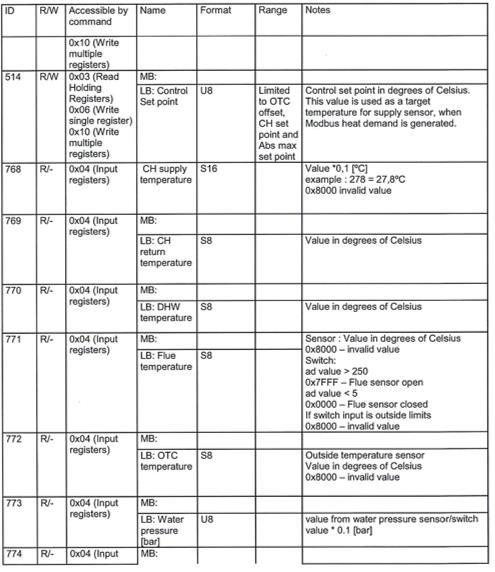
23 INSTALLER S GUI Cascade errors Each boiler has a pottial free alarm relay contact on terminal strip C1 (17, 18) which closes wh an error (Lock, block) occurs, as it would wh operating in standalone mode. In addition, the corresponding error code is displayed on the user interface of the concerned boiler. As the master manages all the heat requests, the same error is also visible on the master display. An reset can be done from either the master or boiler with the error, after resolving the problem. In the upper right corner of the master display, the number of the boiler with the error is indicated. Evtually the alarm relay output of the master boiler will close, to indicate there is a problem in the cascade chain. The power of a single boiler in the chain, ev wh in error mode may not be switched off. Wh switched off, the next boiler(s) cannot be reached by the master, resulting in a cascade bus error (E98). Wh a boiler must be switched off for a longer time, the cascade chain must be rewired temporarily, taking the boiler out of the chain. Terminal strip C3 (pins 4, 5, 6) of the boiler located before the boiler with the error must be connected to terminal strip C3 (pins 1, 2, 3) of the boiler located after the boiler with the error. After re-wiring, perform an AUTO-TECTION again. The new numbers of boilers will be detected. Wh bringing a boiler back into the chain, do not forget to rewire in the original sequce, th to repeat the AUTO-TECTION. The original number of boilers will be displayed. The Cascade-related error codes are E89 to E92, E95, and E97 to E99. Refer to Locking Codes on page 45 for a detail of the cascade-related codes. MODBUS To connect a Modbus controller, an additional kit (terminal strip C3 + shielded cable) is required. Contact your ACV represtative for the correct accessory. In case of a cascade configuration, refer to wiring diagram on previous page. Supported commands The following basic Modbus commands are built in the boiler display: 0x03 Read Holding Registers 0x04 Read input Registers 0x06 Write Single Register 0x10 Write Multiple Registers 0x11 Report Slave ID Wiring procedure 1. Disconnect the 230V supply from the boiler(s) and op the front panel. 2. Mount terminal strip C3 left to the low voltage terminal C2 as shown in the picture on previous page. 3. Connect X06 and X07 to the display. Do not replace the existing connection on X03 used for the diagnostic connector. 4. For Modbus connections only use pins 7 (GND), 8 (A), 9 (B) of terminal strip C3. 5. Use a 3 wire (shielded) cable and route it through the bottom (low voltage) cable guide. Electrical connections MODBUS register map To be connected to The table below shows the Modbus register map. Remark Terminal strip C3 X06 and X07 on boiler display Refer to diagram on previous page Modbus controller Configuration parameters Strip C3, pins 7 (GND), 8 (A) and 9 (B) The Modbus communication line is set to 38,400 b/s by default and can be changed from the Technician mu via the boiler display (Technician mu, system settings, boiler parameters, Modbus). In addition, the default communication frame is set to 8 bit, 1 stop, parity none (8N1). The default Modbus address is 1. 22

24 INSTALLER S GUI 23
 - C53(x) - C63(x), but it can also be connected as an op appliance in category B23, which can operate with a")
 system.")
25 APIANCE DCRIPTION MOLS - COMPACT CONNS The Compact Conds is a floor-installed gas condsing boiler meeting the requiremts of currt HR-Top standards in Belgium. The boiler is certified compliant with EC standards as a connected appliance: C33(x) - C53(x) - C63(x), but it can also be connected as an op appliance in category B23, which can operate with a positive pressure. The boiler is a room-sealed boiler, equipped with a cast aluminium heat-exchanger As standard the boiler is programmed to operate with an on-off room thermostat. It can also be operated using either an optional 0-10V signal, or an Outside temperature control (OTC) system. The boiler also features an optional function for digital communication with room thermostats. An external DHW tank with a thermostat or ssor can be installed in the system. It will be controlled by the built-in MAXSys controller. Among the operating modes, the boiler can operate either in holiday mode or in Eco mode, taking into account the user s schedules. The boiler also features a built-in frost protection mechanism, as well as an anti-freeze function that will protect both the appliance and the system. For more information and details on the boiler s capabilities, refer to Principles of Operation on page Key 7 1. Chimney connection Auto air vt 3. Fan 4. Heating return and return NTC 5. Fill and drain valve (+ water pressure ssor) 6. Air inlet ( 110) 7. Vturi 8. MAXSys Controller 9. Gas valve 10. Control panel with display and pressure gauge 11. Heating supply 12. Flow NTC 13. Ignition and ionization electrodes (2x) 14. C1 & C2 terminal strips for electrical connections 15. Air pressure switch (backside) 16. Inspection sump cover 17. Cast aluminium heat exchanger 18. Condsate trap (siphon) 19. Siphon pressure switch + flue gas NTC 20. Inspection cover 21. Gas pipe 22. Overheat limiter switch 23. Flame sight glass
26 TECHNICAL CHARACTERISTICS DIMSIONS COMPACT CONNS [M] [M] Min. of flue pipe mm Drained weight Kg Clearance required (on access side(s)) mm
27 TECHNICAL CHARACTERISTICS ELECTRICAL CHARACTERISTICS COMPACT CONNS COMPACT CONNS Main Characteristics Rated voltage V~ Rated frequcy Hz Electrical consumption W Electrical consumption in standby W Class IP 00b 00b 00b 00b Fuse A Min cross section of supply wire : 3 x 1.0 mm 2 NTC RISTANCE Internal NTC (Flow/Return/Flue) : 12 K [Ω] at 25 C Outdoor ssors : 12 K [Ω] at 25 C WIRING DIAGRAM AND ELECTRICAL CONNECTIONS Ref Description To be connected to BC Burner Control D Display C1 230V Connector (terminal strip) Pins 0 (PE), 1 (L) and 2 (N) to be used for supply wire connection C2 Low voltage Connector (terminal strip) C3 Optional Cascade/Modbus terminal strip (refer to Integrated Cascade Functionality on page 18 CH-P Ctral Heating pump Strip C1, pins 11 (PE), 9 (L) and 10 (N) (see A-P if 3WV installed) DHW-P Domestic Hot Water pump Strip C1, pins 6 (PE), 7 (L) and 8 (N) OR Strip C1, pins 11 (PE), 9 (L) and 10 (N) if 3WV installed PWM-P Modulating pump Strip C1, pins 14 (PE), 12 (L) and 13 (N) A-P HE Appliance Pump (CH) (max 0,8 A) (if 3WV installed) Heat exchanger PWM signal : Strip C2, pins 14 (PWM signal) and 13 (PWM ground) Strip C1, pins 3 (PE), 4 (L) and 5 (N) Ref Description To be connected to MT NTC1 NTC2 NTC3 Overheat limit switch Flow temperature ssor Return temperature ssor Domestic Hot Water ssor or switch (12 kω at 25 C) Strip C2, pins 7 and 8 NTC4 Outside temperature ssor or switch Strip C2, pins 5 and 6 NTC5 Flue gas temperature ssor NTC6 Cascade ssor Strip C2, pins 15 and 16 WPS Water pressure switch APS Air pressure switch SPS Siphon pressure switch GPS Gas pressure switch GV Gas valve S On/Off switch 3WV 3-way valve Strip C1, pins 6 (PE), 7 (L) and 8 (N) (+ pin 9, if electric 3WV) OT-RT Op Therm, Room Thermostat On/Off (24 Vdc, 5mA), 0-10 V OT et RT : Strip C2, pins (for automatic recognition) 0-10 V : strip C2, pins 3 (-) and 4 (+) (+ short cut installed betwe pins 1 + 2) OTC Outdoor Temperature Control 12K Strip C2, pins (+ short cut installed betwe pins 1 + 2) F Fuse SPS-B Siphon pressure switch block (pottial free contact, 24 Vdc) B-L Burner lock (Err 3) (pottial free contact, 24 Vdc) A Alarm pottial free contact (pottial free relay output, 230 Vac, max 0,8 A) C-P Cascade Pump pottial free contact (pottial free relay output, 230 Vac, max 0,8 A) B-B Burner block (Err 77) (pottial free contact, 230 Vac,) PE Earth cable or connector Fr Frame MP CP FP Mounting Plate Cover Plate Front Plate Geral remark Use the right lower grommet to route the low voltage cables from C2, and the 2 right upper grommets for the 230V connections from C1. 26
28 TECHNICAL CHARACTERISTICS 27
29 TECHNICAL CHARACTERISTICS COMBUSTION CHARACTERISTICS GAS CATEGORI Input (PCI) COMPACT CONNS max kw min kw Output at 100% (80/60 C) kw Efficicy at 100% (80/60 C) % (50/30 C) % Efficicy at 30% load (677) % NOx (Class 5) Weighted mg/kwh CO Max. output mg/kwh CO 2 Max gas flow rate G20/G25 Temp. of flue gases Mass flow rate* of flue gases Max. output %CO Min. output %CO G20 (20 mbar) m³/h G25 (25 mbar) m³/h Nominal C Max. C Min. C Nominal g/s at min output g/s * Mass flow rate values were calculated for G20 with an air factor of 1.3. Country code AT BE BG CH CY CZ DK EE FI GB GR HR IE LI LT LU LV NO PT RO SE SI SK SL Gas type G20 G25 G20 G25 Pressure (mbar) Category I 2H I 2E(R) I 2H I 2H I 2H I 2H I 2E I 2H I 2H I 2H I 2H I 2Esi I 2H I 2H I 2H I 2H I 2H I 2H I 2H I 2E I 2H I 2L I 2EK I 2H I 2H I 2H I 2E I 2H I 2H I 2H I 2H I 2H 28
30 TECHNICAL CHARACTERISTICS PNEUMATIC CONNECTIONS HYDRAULIC CHARACTERISTICS COMPACT CONNS Main Characteristics Capacity (primary) L Max. operating pressure of primary bar circuit Water pressure drop (primary circuit) mbar (Δt = 20 K) Min. required flow rate m 3 /h 5,800 7,200 8,700 10,000 HYDRAULIC PRSURE DROP CURVE OF THE BOILER Compact Conds - Pressure drop vs Water flow Compact Conds 170 (5 sections) and 300 (8 sections) Pressure drop (mbar) 120,0 110,0 100,0 90,0 80,0 70,0 60,0 50,0 40,0 30,0 Type NominalF low 7,2[ m 3 /h] 9[ m 3 /h] 10,8 [m 3 /h] 12,6 [m 3 /h] 20,0 10,0 0, Water flow (m 3 /h) MAXIMUM OPERATING CONDIONS Maximum Service Pressure * - Primary circuit :... 6 bar Maximum Operating Conditions - Maximum temperature (primary) : C Compact Conds 210 (6 sections) and 250 (7 sections) The siphon pressure switch, connected to the sump (P1), prevts overflow of the siphon in case of too high back pressure in the chimney. The air pressure switch, (P1 and P2), connected to the vturi, checks the amount of air (by means of a Δp measuremt) before start. Water Quality See "Recommdations for the Prevtion of Corrosion and Scaling in Heating Systems" on the following page. * The hydraulics of the boiler have be tested according to , and the boiler is classified as a pressure class 3 appliance. 29
31 TECHNICAL CHARACTERISTICS RECOMMDATIONS FOR THE PREVTION OF CORROSION AND SCALING IN HEATING SYSTEMS How oxyg and carbonates can affect the heating system Oxyg and dissolved gasses in the water of the primary circuit contribute to the oxidation and the corrosion of the system componts that are made of ordinary steel (radiators,...). The resulting sludge is th deposited in the boiler exchanger. The combination of carbonates and carbon dioxide in the water results in the formation of scale on the hot surfaces of the installation, including those of the boiler exchanger. These deposits in the heat exchanger reduce the water flow rate and thermally insulate the exchange surfaces, which is likely to damage them. Sources of oxyg and carbonates in the heating circuit The primary circuit is a closed circuit; the water it contains is therefore isolated from the mains water. Wh maintaining the system or filling up the circuit, water rewal results in the addition of oxyg and carbonates in the primary circuit. The larger the water volume in the system, the larger the addition. Hydraulic componts without an oxyg barrier (PE pipes and connections) admit oxyg into the system. Prevtion Principles 1. Clean the existing system before installing a new boiler - Before the system is filled, it must be cleaned in accordance with standard Chemical cleaning agts can be used. - If the circuit is in bad condition, or the cleaning operation was not efficit, or the volume of water in the installation is substantial (e.g. cascade system), it is recommded to separate the boiler from the heating circuit using a plate-to-plate exchanger or equivalt. In that case, it is recommded to install a hydrocyclone or magnetic filter on the installation side. 2. Limit the fill frequcy - Limit fill operations. In order to check the quantity of water that has be added into the system, a water meter can be installed on the filling line of the primary circuit. - At total hardness of 11,2 ºD (= 2 mmol/liter) the total volume of filled, refilled and topped up water must not exceed 20 liters/kw. If this hardness value is exceeded th the total amount of filling, refilling and topping up water is calculated using the following formula : (11/hardness in ºD) x value giv above. Example ; in case of water hardness of 15 ºD : (11/15) x 20 = 14,7 ltr/kw. If larger values are achieved the water should be softed. The water may only be partly softed until a value of 20 % of its original value, so if the initial hardness is 15 D, th it may only be softed to 3,0 ºD Note that water softing by means of ion exchange principle is not allowed - Never fill the installation with de-mineralised or distilled water because it will corrode the aluminium heat exchanger severely - Automatic filling systems are not recommded. - If your installation requires frequt water refilling, make sure your system is free of water leaks. - Inhibitors may be used in accordance with standard Limit the presce of oxyg and sludge in the water - A de-aerator (on the boiler flow line) combined with a dirt separator (upstream of the boiler) must be installed according to the manufacturer s instructions. - ACV recommds using additives that keep the oxyg in solution in the water, such as Fernox ( and Stinel ( products. - The additives must be used in accordance with the instructions issued by the manufacturer of the water treatmt product. 4. Limit the carbonate conctration in the water - The fill water must be softed if its hardness is higher than 20 fh (11,2 dh). - Check regularly the water hardness and ter the values in the service log. - Water hardness table : Water hardness fh dh mmolca(hco3)2 / l Very soft Soft Fairly hard Hard Very hard > 42 > 23.5 > Control the water parameters - In addition to the oxyg and the water hardness, other parameters of the water must be checked. - Treat the water if the measured values are outside the range. Acidity 7,2 < ph < 8,5 Conductivity Chlorides Iron Copper < 400 μs/cm (at 25 C) < 125 mg/l < 0,5 mg/l < 0,1 mg/l 30
32 INSTALLATION SAFETY INSTCTIONS FOR THE INSTALLATION PACKAGE CONTTS Geral remark The connections (electrical, flue pipe, hydraulic, gas/fuel) must be carried out in accordance with currt standards and regulations in force. Esstial recommdations for the correct operation of the appliance The boiler must be installed in a dry and protected area, with an ambit temperature comprised betwe 0 and 45 C. Install the appliance to sure easy access at all times. Make sure that the mains water used to fill the boiler has a minimum pressure of 1.2 bar. Make sure to install a pressure reducing valve set at 4.5 bar if the mains supply pressure is in excess of 6 bar. If works need to be performed (in the boiler room or close to the air vts), make sure to turn off the boiler to prevt dust from tering and accumulating in the boiler heating system. Esstial recommdations for safety Install the boiler on a base made of non-combustible materials. Do not store any corrosive products, paint, solvts, salts, chloride products and other detergt products near the appliance. Make sure that all air vts are unobstructed at all times. A condsation outlet connected to the sewer must be fitted close to the boiler to prevt the condsation products from the flue pipe from running into the boiler. Install a condsate neutralisation system if required by national and/or local regulations and have it cleaned regularly. The horizontal flue pipes must be installed with a slight slope of 5 cm per meter, so that the acid condsation water flows to a condsate recovery container and does not damage the heating body. Only use ACV flue systems to connect this appliance to sure that the pipe and connection diameters all match. Esstial recommdations for the electrical safety Only an approved installer is authorized to carry out the electrical connections. Install a 2-way switch and a fuse or circuit breaker of the recommded rating outside the appliance, so as to be able to shut power down wh servicing the appliance or before performing any operation on it. Isolate the external electrical supply of the appliance before performing any operation on the electrical circuit. This appliance is not intded for use by persons (including childr) with reduced physical, ssory or mtal capabilities, or lack of experice and knowledge, unless supervised or unless they have be giv instruction concerning the use of the appliance by a person responsible for their safety. The Compact Conds boilers are delivered assembled and packaged. At product reception and after removal of packaging, check the package contts and that the appliance is free of damages. Contts Boiler Installation, Operation and Maintance Instructions, for the User and the Installer TOOLS REQUIRED FOR THE INSTALLATION BOILER PREPARATION GAS pressure (mbar) 1. Remove the sealing/protection caps from the connection tubes. Some dirty water might come out. 2. Fill the condsate trap with water by pouring some water into the cast aluminium exhaust connection at the back. 3. Make all the required electrical connections of accessories (pumps, thermostats, etc.). Refer to Wiring Diagram and Electrical Connections on page
33 INSTALLATION HEATING CONNECTION Typical connection - high temperature Description 1. Isolating valve 2. Heating pump 3. Filling valve 4. Check valve 5. Safety valve 6. Expansion vessel 7. Drain valve 8. Auto air bleed valve Typical connection - low temperature Description 1. Isolating valve 2. 3-way mixing valve 3. Plate-to-plate heat exchanger 4. Heating pump 5. Safety valve 6. Filling valve 7. Check valve 8. Expansion vessel 9. Drain valve 10. Auto air bleed valve Cold water Hot water 3 REMOVAL AND INSTALLATION OF THE ONT AND SI PANELS Set-up conditions External power supply isolated Removal Procedure Front panel 1. Using a cross-head screwdriver, release two screws (1) located at the top of the front panel. Retain for re-installation. 2. Pull slightly the panel top towards you, th lift the whole panel to disgage the bottom lug from the boiler casing mounting slot. 3. Disconnect the earth wire. Side panels 1. Release 3 screws at the back of the boiler and remove the top cover. 2. On the side where access is required, release the attaching screws from the back, the top and the front locations. Retain the screws for re-installation. 3. Remove the panel. Installation procedure Side panels 1. Place the panel in position. 2. Install and tight the screws retained at removal in their front, top and back locations. 3. Install the top cover and tight 3 attaching screws retained at removal. Front panel 1. Connect the earth wire. 2. Hold the front panel at a slight angle to gage the lower lug of the front panel in the boiler casing mounting slot. 3. Lower panel in the slot and push the top of the panel toward the boiler. 4. Install 2 screws (1) retained at removal. Follow-on tasks None 1 Esstial recommdations for the correct operation of the system As there is no built-in safety group (safety valve + pressure release valve) in the boiler, make sure to install them in the system. As there is no built-in CH pump in the boiler, the installer must provide one in the system. The heating circuit must be designed so as to sure a continuous flow in the boiler; this flow may be obstructed if all the thermostatic valves are closed. In this case, install a bypass. 32
34 INSTALLATION CHIMNEY CONNECTION It is mandatory to vtilate the boiler room. The high or low air vt oping dimsions depd on the boiler power and the boiler room size. Refer to the local regulations in force. C 33 C 33 C 53 FLUE PIPE CONNECTION TYP B23 It is mandatory to use ACV flue systems to connect the appliance. : Connection to an exhaust duct that discharges the combustion products outside the room where it is installed, with the combustion air being drawn directly from the boiler room. C33(x) : Connection using pipes fitted with a vertical terminal that simultaneously takes in fresh air for the burner and discharges combustion products outside through opings that are either conctric or close ough together to be subjected to similar wind conditions, i.e. opings shall fit inside a square of 50 cm for boilers up to 70 kw and inside a square of 100 cm for boilers above 70 kw. C53(x) : Connection to separate ducts for supplying combustion air and discharging combustion products; these ducts may d in zones with differt pressure levels, but are not allowed to be installed on opposite walls of the building. C63(x) : Type C boiler meant to be connected to a system for supplying combustion air and discharging combustion products, that is approved and sold separately (Prohibited in Belgium). Terminals for the supply of combustion air and for the evacuation of combustion products are not allowed to be installed on opposite walls of the building. See also the following additional specifications: Maximum allowable draught is 200 Pa. Maximum allowable pressure differce betwe combustion air inlet and flue gas outlet (including wind pressures) is 150 Pa. Condsate flow is allowed into the appliance. Maximum allowable recirculation rate of 10% under wind conditions. Only use approved C63 flue system B 23 33
35 INSTALLATION CALCULATION OF THE FLUE PIPE LGTH Wh connecting the flue pipes, make sure not to exceed the maximum flue pressure drop value, or the maximum lgth in meters of straight pipes recommded for the product, otherwise the system pressure might decrease. The flue pipe dimsions can be calculated using the following tables, indicating the corresponding lgth in meters of straight pipes, applied to each of the connection componts, as well as the pressure drop value per compont. Th compare the calculation result to the recommded maximum flue pipe lgth or maximum pressure drop value for each type of Compact Conds model. The following tables are based on ACV equipmt and cannot be applied as a rule. Maximum lgth (in meters) for C63 connection type* Model Max. allowed pressure drop Parallel air/flue gas Ø150/ m m 150 Pa** m m * Without terminal, condsate trap and bd. ** Sum of flue + air pressure drop Pressure drop (Pa) per compont Model Compont Flue Air Flue Air Flue Air Flue Air Straight pipe (1m) Elbow (90 ) Elbow (45 ) C33 Terminal Ø200 mm Ø150 mm Ø200 mm Ø150 mm Ø200 mm Ø150 mm Ø200 mm Ø150 mm B23 Terminal Ø200 mm C53 Terminal Condsate trap Ø200 mm T + Bd 90 Expander 110/150mm Ø200 mm Ø150 mm

36 INSTALLATION GAS CONNECTION SYSTEM CONFIGURATIONS Esstial recommdations for safety The gas connection must comply with all applicable local standards and regulations, and the circuit will be equipped with a gas pressure regulator as required. The gas burners are factory preset for use with natural gas [equivalt to G20]. The CO 2, gas flow rate, air flow rate and air/gas supply parameters are factory-preset and may not be modified in Belgium, except for type I 2E(R)B boilers. Do not change the OFFSET (A) setting of the gas valve: it is factory-preset and sealed. The Compact Conds boilers can be setup in differt types of systems, either high or low temperature, or both, with or without Domestic Hot Water tank. They can also be configured in a Cascade system (using the integrated cascade funtion or using an external controller). Refer to Integrated Cascade Functionality on page 18. Only the hydraulics and electronics systems can be connected in a cascade, not the flue system. It is up to the installer to determine the best solution to achieve the results the user is expecting. One basic configuration is shown in this manual (see next page). For any other configuration, please contact your ACV represtative. Esstial recommdations for the correct operation of the appliance Refer to the technical characteristics of this manual or to the burner documtation to know the connection diameters. Bleed the gas duct and check thoroughly if all the boiler tubes, both internal and external, are tight. Check the system gas pressure. Refer to the table containing all relevant data in the section "Technical characteristics". Check the boiler electrical connection, the boiler room air vt system, the tightness of flue gas outlet pipes and of the burner chamber plate. Control the gas pressure and consumption at appliance start up. Check the boiler CO 2 adjustmt (refer to the adjustmt procedure and the technical data). A BOILER LOAD SETTINGS At the factory, the maximum load of the boiler was measured within 5% tolerance from the nominal load. In the field, the load can decrease due to more resistance in the boiler, the air inlet or the exhaust outlet or due to a malfunction of the fan. At maximum load, the system should be designed for a nominal ΔT of 15 K to 20 K. Wh the ΔT is higher than 25 K, the boiler cannot run on maximum load anymore and will start to modulate because of an insufficit water flow through the boiler. Flow and return temperatures can be read in the boiler information mu (in the DIAGNOSTICS mu, refer to User s mu and parameter descriptions on page 9 and Installer s mu and parameter descriptions on page 14). Valves, malfunctioning pumps, dirt, corrosion products from the system, dirty filters etc. can have a negative impact on water flow through the boiler. Before ignition the boiler control checks ΔP aps during pre-purge. During burner operation, this check will be carried out. If the value is decreasing over the years, this could indicate e.g. malfunctioning of the fan, polluted air inlet, polluted burner, polluted heat exchanger or polluted exhaust system. Siphon pressure (P SPS) should be smaller than the maximum allowable flue resistance. If P SPS is too high (> 8,3 mbar), the boiler will be stopped. In this case, the exhaust system is probably blocked. Refer to Troubleshooting on page 43 for more information and to Maintance on page
37 INSTALLATION BASIC CONFIGURATION - COMPACT CONNS: HIGH TEMPERATURE HEATING CIRCU CONTROLLED BY ROOM THERMOSTAT AND OPTIONAL OUTDOOR SSOR. EM DCRIPTION QTY ELECT. TERMINALS TO CONNECT TO** 1 Room thermostat 1 Strip C2 Pins 1 & 2 2 Outdoor temperature ssor, 12kΩ 1 Strip C2 Pins 5 & Plate-to-Plate heat exchanger 1-3 Circulation pump 2 -- MAXSys Block Diagram The heating system (radiators) is controlled by an On/Off room thermostat. In this configuration, the boiler constantly adapts its operation to the outdoor temperature, if an outdoor temperature ssor is connected. The heating pump is triggered as soon as the room thermostat gerates a heat demand. * The illustrations are for information only. For more details on the required accessories, refer to your ACV represtative. ** For electrical detail, refer to wiring diagram in Wiring Diagram and Electrical Connections on page
38 STARTING UP SAFETY INSTCTIONS FOR STARTING UP FILLING THE HEATING CIRCU Geral remark In normal operation, the burner starts automatically as soon as the boiler temperature drops below the preset temperature. Esstial recommdations for safety The componts inside the control panel may only be accessed by an approved installer. Set the water temperature in accordance with usage and local plumbing codes. Make sure that the heating circuit filling valve is closed once the starting up process is complete. TOOLS REQUIRED FOR STARTING UP If the system is fitted with an external hot water tank, first put the DHW circuit under pressure before pressurizing the heating (primary) circuit. Refer to the hot water preparation tank manual for more information. Set-up conditions External power supply isolated DHW circuit (if any) under pressure Filling procedure 1. Op the isolating valves (1). 2. Make sure that the drain valve (3) is tightly closed. 3. Op the filling valve (2). 4. Once the system is bled from air, bring the pressure to the static pressure betwe1.5 bar and 2 bar. 5. Close the filling valve (2) Follow-on task 1. Check there is no leak. GAS pressure (mbar) CHECKS BEFORE STARTING UP Esstial recommdation for safety 1 2 Check the tightness of the flue pipe connections. Esstial recommdation for the correct operation of the appliance 3 1 Control the tightness of the hydraulic circuit connections. 37

39 STARTING UP STARTING UP THE BOILER Set-up conditions All connections made Condsate trap full of water Electrical power supply on Gas supply op Hydraulic circuit full of water Procedure 1. Check that there is no gas leak. 2. Set the ON/OFF master switch on the I position. 3. If a room thermostat is installed, possibly increase the temperature set-point to gerate a demand. 4. Check that the gas pressure, siphon pressure and water pressure contacts are closed. If not, the boiler will block and display the E76 error code. 5. Check the gas pressure and allow the boiler to heat up for a few minutes. 6. Check there is no leak at flue-gas joints. 7. Check and adjust the burner according to local standards and regulations, refer to Checking and Adjusting the Burner on page Set the ctral heating temperature to the required value using the control panel. Refer to Installer s mu and parameter descriptions on page After 5 minutes of operation, bleed the heating circuit until all air is evacuated and restore a 1.5 bar pressure. 10. Bleed the ctral heating circuit once again and top it up with water to get the required pressure, if necessary. 11. Make sure that the ctral heating system is properly balanced and, if needed, adjust the valves to prevt certain circuits or radiators from getting a flow rate that is far above or below the set rate. Follow-on tasks 1. Check that there are no leaks. 2. Check that the flow rate in the appliance is sufficit as follows : Operate the boiler at maximum power Once the temperatures are stable, read out the supply and return temperatures Check that the differce betwe the supply and return temperature is equal to or lower than 20k. If the Delta T is higher than 20k, check the pump settings/specifications. CHECKING AND ADJUSTING THE BURNER Wh the burner operates at full power, the CO 2 rate must be within the limits mtioned in the technical characteristics, (see Combustion Characteristics on page 28). Set-up conditions Operating boiler Procedure 1. Check if the MAXSYS parameters are set to meet the user's requiremts (refer to Installer s mu and parameter descriptions on page 14), and change them if required. 2. Put the boiler to maximum power mode (refer to Installer s mu and parameter descriptions on page 14, chimney sweeper function). The boiler is equipped with an automatic gas/air regulator. This means that the amount of gas is regulated according to the amount of air. 3. Using a pressure tester, check that the dynamic gas pressure at the gas valve is at least 18 mbar. 4. Allow the appliance to heat for a few minutes until its temperature is stable. 5. Measure the burner combustion by placing the flue gas analyser probe into the measuremt unit port on the flue pipe and compare the CO and CO 2 values displayed with those indicated in the combustion characteristics table. Refer to Combustion Characteristics on page If the CO 2 value differs by more than +0.2% / from the value mtioned in the Combustion Characteristics on page 28, carry out the adjustmt as follows : Turn the throttle to the right to lower the CO 2 perctage (a ½ turn (180 ) gives a change of approximately 0,2 % CO2) 7. Th put the boiler to the minimum power mode (Refer to Installer s mu and parameter descriptions on page 14). 8. Allow the boiler to stabilize for a few minutes. 9. Measure the CO 2 level. It must be lower than the value at full power, with a maximum of 0.5%. In case of significant deviation, please contact ACV's Maintance departmt. Follow-on tasks 10. Fill in the service log with the required initial values, in order to be able to compare the boiler changes over time. Refer to Service log on page
40 MAINTANCE SAFETY INSTCTIONS FOR THE BOILER MAINTANCE PERIODIC BOILER MAINTANCE TASKS Esstial recommdations for the electrical safety Turn off the boiler by pushing on the ON/OFF master switch. Isolate the external power supply of the appliance before performing any operation, unless it is required to take measuremts or perform system setup. Esstial recommdations for safety Tasks Periodic inspection End-user Frequcy 1 year 2 years Professional Water flowing out of the drain valve may be extremely hot and could cause severe scalding. Check the tightness of the flue pipe connections. 1. Make sure that the system water pressure is at least 1 bar wh cold. Top up the system if necessary, adding small quantities of water at a time. In case of repeated fills, call your installer. X X Esstial recommdations for the correct operation of the appliance 2. Check that there is no water on the floor under the boiler. Call your installer if there is. X X It is recommded to have the boiler and the burner serviced at least once a year or every 1,500 hours. More frequt servicing may be required depding on boiler use. Please consult your installer for advice. The boiler and burner maintance will be carried out by a qualified gineer, and the defective parts may only be replaced by guine factory parts. Control the tightness of the hydraulic circuit connections. Make sure to replace the gaskets of the removed items before reinstalling them. TOOLS REQUIRED FOR MAINTANCE 3. Check that no error code is displayed on the control panel. Call your installer if necessary. 4. Check that all gas, hydraulic and electrical connections are correctly fasted and tight. 5. Check the flue gas exhaust: correct fasting, correct installation, no leaks or clogging. 6. Check the combustion parameters (CO and CO 2 ), see Checking and Adjusting the Burner on page Check visually the heating body: no evidce of corrosion, soot deposits or damages. Carry out all required cleaning tasks, repairs and replacemts that might be required. X X X X X X 8. Check the electrodes, see Removal, Check and Installation of the Burner Electrodes on page 40 X GAS pressure (mbar) 9. Remove the burner and clean the exchanger, see Removal, Check and Installation of the Burner on page 41 and Cleaning the Exchanger on page Check that the condsate trap is not clogged. If it is, remove it, clean it, and reinstall it.* X X 11. Op and inspect the condsate recovery dish.* X BOILER SHUT-DOWN FOR MAINTANCE 12. If a condsate neutralisation system is installed, check it and have it cleaned. X X 1. Switch the boiler off using the ON/OFF master switch and isolate the external power supply. 2. Close the gas supply valve of the boiler. * To access the condsate trap and the condsate recovery dish, op the side panel, refer to Removal and Installation of the Front and Side Panels on page
 circuit. Water flowing out of the drain valve may be extremely hot and could cause severe scalding. Keep people away from the hot water discharge.")
41 MAINTANCE DRAINING THE HEATING CIRCU OF THE BOILER Esstial recommdations for safety If the system is fitted with an external hot water tank, isolate the DHW circuit before draining the heating (primary) circuit. Water flowing out of the drain valve may be extremely hot and could cause severe scalding. Keep people away from the hot water discharge. Set-up conditions Boiler switched off using the ON/OFF master switch DHW circuit (if any) isolated External power supply isolated Gas supply closed Heating circuit draining procedure 1. Close the isolating valves (1). 2. Connect the drain valve (2) to the sewer with a hose. 3. Op the drain valve (2) to empty the heating circuit of the boiler. 4. Close the drain valve (2) once the heating circuit of the boiler is empty and remove hose as required. Follow-on task 1. None REMOVAL, CHECK AND INSTALLATION OF THE BURNER ELECTROD Esstial recommdations for the correct operation of the appliance Remove the electrodes to control them in case of ignition problems. Set-up conditions Boiler shut down External power supply isolated Gas supply closed Front panel op, refer to Removal and Installation of the Front and Side Panels on page 32. Removal procedure 1. Disconnect all the cables from the electrodes. 2. Remove two mounting screws (1) and retain them for re-installation. 3. Remove the 2 electrodes (2) and their gasket (3). 4. Check the correct alignmt of the electrode ds and that the gap corresponds to the value indicated on the figure below. 5. Replace the electrodes if required. Installation procedure 1. Install a new gasket. 2. Install both electrodes (2) using their two retained screws (1). Follow-on tasks 1. Reconnect all the cables to the electrodes. 3,5± 0,5 mm
INSTALLATION, OPERATION AND MAINTENANCE INSTRUCTIONS
 INSTALLATION, OPERATION AND MAINTANCE INSTCTIONS for the Installer and the User HeatMaster 5-5 - 45-70 - 85-0 TC A00477-6646900 D Adddum - iring Diagrams - Detail of X00 Terminal APICAIL : 664900 - Rev
SMART Line Smart E
 INSTALLATION, OPERATION AND MAINTENANCE INSTCTIONS, for the User and the Installer SMART Line 30-60 - 20-240 - 300 Plus 20-240 - 300 A002858-66Y200 B TABLE OF CONTENTS GENERAL RECOMMENDATIONS...4 PRODUCT
INSTALLATION, OPERATION AND MAINTENANCE INSTRUCTIONS,
 EN INSTALLATION, OPERATION AND MAINTENANCE INSTCTIONS, for the User and the Installer HR i 320-600 - 800 A1002237-661Y1300 B EN EN TABLE OF CONTENTS GENERAL RECOMMENDATIONS...3 PRODUCT INFORMATION...4
INSTALLATION, OPERATION AND MAINTENANCE INSTRUCTIONS, for the User and the Installer. SMART Line. Smart ME A Y2000 B
 INSTALLATION, OPERATION AND MAINTENANCE INSTCTIONS, for the User and the Installer SMART Line Smart ME 00-300 - 400-600 - 800 A00859-66Y000 B TABLE OF CONTENTS GENERAL RECOMMENDATIONS...4 PRODUCT INFORMATION...5
INSTALLATION, OPERATION AND MAINTENANCE INSTRUCTIONS,
 INSTALLATION, OPERATION AND MAINTENANCE INSTCTIONS, for the User and the Installer EN SMART Line SL 320-420 - 420 Duplex - 600 A002875-66Y300 A EN TABLE OF CONTENTS GENERAL RECOMMENDATIONS...4 Energy labelling...
Technical manual MARK MEGAFLEX
 Technical manual EN MARK MEGAFLEX 0660440 1 INSTRUCTIONS FOR USER If you have questions concerning the use of your boiler or heating system, please ask your installer. It is in your own interest and that
INSTALLATION, OPERATION AND MAINTENANCE INSTRUCTIONS BNE 1 - BNE 2 664Y6000 D
 INSTALLATION, OPERATION AND MAINTANCE INSTRUCTIONS BNE 1 - BNE 2 664Y6000 D Addendum - Additional Safety Instructions for Appliances APPLICABILITY : 664Y5000 - Rev C - N2 Condens, Installation, Operation
Installation, operation and maintenance instructions. HRi Y1300-A
 Installation, operation and maintance instructions HRi 321-601 - 800 Table of contts Geral Recommdations...4 User's Guide...5 Control Panel... 5 Appliance Description...6 Models - HRi 321 601-800... 6
INSTALLATION, OPERATION AND MAINTENANCE INSTRUCTIONS,
 INSTALLATION, OPERATION AND MAINTENANCE INSTCTIONS, for the User and the Installer SMART GREEN 130-160 - 210 A1002064-661Y3000 B TABLE OF CONTENTS GENERAL RECOMMENDATIONS...4 PRODUCT INFORMATION...5 Energy
INSTALLATION, OPERATION AND MAINTENANCE INSTRUCTIONS
 INSTALLATION, OPERATION AND MAINTANCE INSTCTIONS BNE 2 Conds 21.8 kw 664Y5900 D TABLE OF CONTTS GERAL RECOMMDATIONS...4 USER'S GUI...5 Instructions for the d-user... 5 Periodic checks... 5 APIANCE DCRIPTION...6
prestige Control Application Supplement - TriMax
 prestige Control Application Supplement - TriMax L I S T E D WARNING This document is intended to be used by a factory trained and qualified heating contractor or service technician only. Read all instructions
HIGH EFFICIENCY FIRETUBE CONDENSING GAS BOILER
 This manual must be left with owner and should be hung on or adjacent to the boiler for reference. US HIGH EFFICIENCY FIRETUBE CONDENSING GAS BOILER MODELS CHS-85 through CHS-399 APPENDIX A CONTROLLER
Control Application. Supplement - ACVMax
 prestige Control Application Supplement - ACVMax L I S T E D WARNING This document is intended to be used by a factory trained and qualified heating contractor or service technician only. Read all instructions
Installation, operating and. Comfort
 EN Installation, operating and servicing instructions Comfort 00-0 - 60-20 - 20 TABLE OF CONTENTS EN GENERAL Notes Certification CE Standards Packaging SAFETY PRECAUTIONS 5 Symbols used 5 Recommdations
prestige Control Application Supplement - ACVMax
 2015-10 Prestige ACVMax Control Sup 12-14-15_ACVMax_Control 12/15/15 7:36 AM Page 1 prestige Control Application Supplement - ACVMax L I S T E D WARNING This document is intended to be used by a factory
INSTALLATION, OPERATION AND MAINTENANCE INSTRUCTIONS. HeatMaster TC 664Y6800 A
 INSTALLATION, OPERATION AND MAINTENANCE INSTCTIONS HeatMaster 25-35 - 45-70 - 85-120 TC 664Y6800 A TALE OF CONTENTS GENERAL RECOMMENDATIONS...4 USER'S GUI...5 Instructions for the d user... 5 Periodic
prestige Control Application Supplement - TriMax
 prestige Control Application Supplement - TriMax L I S T E D WARNING This document is intended to be used by a factory trained and qualified heating contractor or service technician only. Read all instructions
INSTALLATION, OPERATION AND MAINTENANCE INSTRUCTIONS
 EN INSTALLATION, OPERATION AND MAINTENANCE INSTCTIONS for the Installer and the User N - N2 - N3 eco A00570-664Y7700 B EN TABLE OF CONTENTS GENERAL RECOMMENDATIONS...3 USER S GUI...4 Meaning of Symbols...4
Prestige Solo
 INSTALLATION, OPEATION AND MAINTANCE INSTCTIONS for the Installer and the User Prestige 4-50 - 75-00 - 0 Solo A00500-664600 F TALE OF CONTTS GEAL ECOMMDATIONS... Safety Instructions... USE S GUI...4 Meaning
INSTRUCTION FOR THE USER THC V E OIL BLU
 INSTRUCTION FOR THE THC V E OIL BLU CONTENTS General safety information 4 Precautions 4 Control panel 5 Mode selection 8 User levels 10 Start-up 12 Temporary shutdown 15 Preparing for extended periods
INSTALLATION, OPERATION AND MAINTENANCE INSTRUCTIONS,
 INSTALLATION, OPERATION AND MAINTENANCE INSTCTIONS, for the User and the Installer SMART Line SL 320-420 - 420 Duplex - 600 A1004777-661Y3100 B TABLE OF CONTENTS GENERAL RECOMMENDATIONS...4 Energy labelling...
INSTALLATION, OPERATION AND MAINTENANCE INSTRUCTIONS, for the User and the Installer. SMART Line. Smart ME A Y2000 C
 INSTALLATION, OPERATION AND MAINTANCE INSTCTIONS, for the User and the Installer SMART Line Smart ME 00-300 - 400-600 - 800 A1003499-661Y000 C TABLE OF CONTTS GERAL RECOMMDATIONS...4 PRODUCT INFORMATION...5
INSTALLATION, OPERATION AND MAINTENANCE INSTRUCTIONS
 INSTALLATION, OPEATION AND MAINTANCE INSTCTIONS for the Installer and the User Prestige 4-3 Solo 4-3 Excellce Prestige 4-3 Solo/Excellce : A004335-6646700 D TALE OF CONTTS GEAL ECOMMDATIONS...3 Safety
B-40/B-41 Modulating Temperature Controller
 INSTALLATION & OPERATING INSTRUCTIONS B-40/B-41 Modulating Temperature Controller For Raytherm Boilers & Water Heaters H2 514-4001 WH2 2100-4001 Catalog No. 5000.70 Effective: 12-21-11 Replaces: NEW P/N
USER GUIDE. IMAX XTRA EL kW. For Installation Guide see reverse of book
 USER GUIDE IMAX XTRA EL 320-620kW For Installation Guide see reverse of book When replacing any part on this appliance, use only spare parts that you can be assured conform to the safety and performance
Quickheat 30 weather compensated boiler control
 Quickheat 0 weather compensated boiler control A compact and sophisticated heating controller The compact KM controller is designed for the control of fan assisted boilers with modulating burners. The
Heat 45 & 55. User Instructions FAN POWERED HIGH EFFICIENCY MODULATING DOMESTIC CONDENSING GAS COMBINATION BOILER
 Heat 45 & 55 User Instructions FAN POWERED HIGH EFFICIENCY MODULATING DOMESTIC CONDENSING GAS COMBINATION BOILER CE/PI No. 86-CN-69 Heat 45 - GC No. 41-930-40 Heat 55 - GC No. 41-930-41 These instructions
Aqua Balance. AquaBalance TM CONTROL MODULE QUICK START GUIDE LEGEND
 Aqua Balance AquaBalance TM CONTROL MODULE QUICK START GUIDE 10 1 Domestic Hot Water temperature setpoint decreasing button 2 Domestic Hot Water temperature setpoint increasing button 3 Central Heating
ProCon Boiler Controller Commissioning Quick Reference Guide
 ProCon Boiler Controller Commissioning Quick Reference Guide This sheet is intended as a quick reference guide and should be read in conjunction with the operating and maintenance manual for the boiler
USER'S INFORMATION MANUAL
 USER'S INFORMATION MANUAL WARNING: If the information in this manual is not followed exactly, a fire or explosion may result causing property damage, personal injury or loss of life. Do not store or use
Trinity Tft/Lx Model #s: Tft60-399/Lx Version Date:
 Trinity Tft/Lx Model #s: Tft60-399/Lx150-800 Version Date: 2013-07-26 NEW FEATURES Second Central Heat Input Internal Lead-Lag Control System Sensor Modulation Sensor Alternatives Warm Weather Shutdown
Modulating clock thermostat
 EN Digital timer thermosatat Modulating clock thermostat Installation and Service Manual 123189-AB Contents 1 Preface...4 1.1 General...4 2 Location of the installation...5 2.1 Position of the regulator...5
KIT UNITÀ AMBIENTE E INTERFACCIA A LED KIT ROOM UNIT AND LED INTERFACE RAUMGERÄT UND LED-SCHNITTSTELLE KIT APPAREIL D'AMBIANCE ET INTERFACE À LEDS
 A it KIT UNITÀ AMBIENTE E INTERFACCIA A LED PER IL CONTROLLO DELLA TEMPERATURA AMBIENTE DEL LOCALE en KIT ROOM UNIT AND LED INTERFACE ROOM TEMPERATURE CONTROL ACCESSORY de RAUMGERÄT UND LED-SCHNITTSTELLE
INSTALLATION, OPERATING AND SERVICING INSTRUCTIONS BG 2000-S (V13) RU PL DE IT ES NL EN 1 662Y0600 A
 RU PL DE IT ES NL EN 1 662Y0600 A") INSTALLATION, OPERATING AND SERVICING INSTRUCTIONS G 2000-S 25-35 - 45-55 60-70 - 100 (V13) 1 Index WARNINGS GAS FLOW RATE DIMSIONS SETTINGS PARAMETERS SERVICING THE URNER 3 8 13 OPERATING DESCRIPTION
INSTALLATION, OPERATING AND SERVICING INSTRUCTIONS G 2000-S 25-35 - 45-55 60-70 - 100 (V13) 1 Index WARNINGS GAS FLOW RATE DIMSIONS SETTINGS PARAMETERS SERVICING THE URNER 3 8 13 OPERATING DESCRIPTION
USER'S INFORMATION MANUAL
 USER'S INFORMATION MANUAL WARNING: If the information in this manual is not followed exactly, a fire or explosion may result causing property damage, personal injury or loss of life. Do not store or use
USER MANUAL ACQUAHOME 32 B BLU
 USER MANUAL ACQUAHOME 32 B BLU Dear Customer, Thank you for preferring a T heating unit, a modern, high-quality product that is able to guarantee your maximum well-being for a long period of time, with
1. COMMISSIONING OF THE BOILER en DESCRIPTION FUNCTION BUTTON DESCRIPTION SYMBOL DISPLAY
 RC 06 0712_1403 it - Istruzioni TELECONTROLLO en - Remote controller instruction hu - Utasítás TÁVVEZÉRLÉS ru - Руководство по эксплуатации pl - Instrukcja obsługi { 1. Commissioning of the boiler 26 2.
USERS MANUAL FOR GAS BOILERS
 USERS MANUAL FOR GAS BOILERS PLEASE READ THE MANUAL CAREFULLY: IT CONTAINS IMPORTANT INFORMATION REGARDING SAFETY, INSTALLATION, USE AND MAINTENANCE OF THE APPLIANCE MODELS: NOVADENS 24 NOVADENS 24C NOVADENS
Service Manual Models: 1.0, 1.3, and 1.5
 AWX2-SER_100160837_2000000360_Rev F Service Manual Models: 1.0, 1.3, and 1.5 LOW LEAD CONTENT WARNING This manual must only be used by a qualified heating installer / service technician. Read all instructions,
Operation manual FR EN NL DE IT. intended for professionals and end users. To be saved for future consultation
 Document n 1408-1 ~ 11/02/2010 Control Box FR EN NL DE IT Operation manual intended for professionals and end users To be saved for future consultation Fujitsu General (Euro) GmbH Werftstrasse 20 40549
Great Britain en. Installation, user and service manual. Control panel HMI Gas 310/610 ECO PRO
 Great Britain en Installation, user and service manual Control panel HMI Gas 310/610 ECO PRO Dear Customer, Thank you very much for buying this appliance. Please read through the manual carefully before
1 DOCUMENT REVISION CONTROL ELEMENTS... 9
 CONTENTS Contents 1 DOCUMENT REVISION... 8 2 SOFTWARE VERSION... 8 3 BASIC DESCRIPTION... 8 4 CONTROL ELEMENTS... 9 4.1 BASIC DISPLAYS...10 4.2 CONTROL KEYS...11 4.2.1 Rotary button (Press / Turn)...11
ENVI Boiler Controller
 Rev. 2.6 (01/27/2015) 1004905953 Software versions 112E, BD71, 49A7, 79F2, 8C51,1043, 9820 ENVI Boiler Controller Advanced User s Guide Installation Date: Harsco Industrial, Patterson-Kelley 155 Burson
ProCon 16, 31, 47, 75, 77 & HT. RVA 46. Zone Controller Commissioning Data.
 ProCon 16, 31, 47, 75, 77 & HT. RVA 46. Zone Controller Commissioning Data. The RVA 46 Zone Controller can only be used in conjunction with a RVA47 controlled boiler installation. The RVA46 controller
prestige Control Application Supplement - Type 5 MCBA WARNING
 prestige Control Application Supplement - Type 5 MCBA WARNING This document is intended to be used by a factory trained and qualified heating contractor or service technician only. Read all instructions
Residential Gas Condensing Boiler Greenstar ZBR16/21/28/35/42-3A... ZWB28/35/42-3A...
 70 80 99-00-O Residential Gas Condensing Boiler ZBR//8/35/4-3A... ZWB8/35/4-3A... 70 80 993 (03/03) CA/US Operating Instructions Contents Contents Key to symbols and safety instructions............................
MC200. Users Instructions. HEATING DIVISION Hort Bridge Ilminster, Somerset TA19 9PS Tel: Fax:
 MC200 Users Instructions BSI Registered Firm HEATING DIVISION Hort Bridge Ilminster, Somerset TA19 9PS Tel: 01460 53535 Fax: 01460 52341 FM 414 Ind. & Comm. Air Heaters; Air Moving Equipment; Flues & Chimneys;
EBC20. Instructions for fitting, installation and operation. Read and save these instructions!
 EBC20 UK Instructions for fitting, installation and operation Read and save these instructions! 2 3002878 EBC20 UK 290415 1. Product information............................................... 4 1.1 Delivery.............................................................
CONTENTS PRODUCT GAS TYPE CONVERSION ADJUSTMENTS FAULT & FAILURE. Product Notation Safety Systems Technical Data Main Components Operating Functions
 24 kw Open Flued Gas Combination Boiler (bithermic type) 24 kw Room Sealed Fan Assisted Gas Combination Boiler (bithermic type) 24 kw Room Sealed Fan Assisted Gas Combination Boiler (monothermic type)
ModSync Sequencing System Installation & Operation Manual. For use with Fulton Steam Boilers.
 ModSync Sequencing System Installation & Operation Manual For use with Fulton Steam Boilers. Revision 3.0 8/21/2008 - 2 - Table of Contents Introduction Page 4 Features Page 4 Sequence of Operation Page
Multi Boiler Guide. Kit #
 Multi Boiler Guide Kit # 550002186 Technical Support @ 800-325-5479 Phone: (315) 797-1310 Fax: (866) 432-7329 e-mail: info@ecrinternational.com web site: www.ecrinternational.com Information and specifications
User Manual for model
 User Manual for model RKA 24 /20 Wall mounted storage combi boiler premix condensing boiler CE 0694 Technical specification RADIANT BRUCIATORI S.p.A. Montelabbate RKA 24.20 - RAD - ING - MAN.UT - 1309.1
Service Manual. w/con X US Interface Models: Series: & WARNING
 100208044_2000004590 Rev N w/con X US Interface Models: 751-6001 Series: 100-101 & 110-111 WARNING This manual must only be used by a qualified heating installer / service technician. Read all instructions,
ProCon 16, 31, 47 & 75. RVA 63 Boiler and Circuit Controller Commissioning Data.
 ProCon 16, 31, 47 & 75. RVA 63 Boiler and Circuit Controller Commissioning Data. The RVA63 controller can be utilized to control the following system configurations via LPB communication. Equipment Required
INSTALLATION AND OPERATING INSTRUCTIONS BIOCLASS HM OD (FOR EXTERNAL USE)
") INSTALLATION AND OPERATING INSTRUCTIONS BIOCLASS HM OD (FOR EXTERNAL USE) Thank you for choosing a DOMUSA TEKNIK heating boiler. Within the product range offered by DOMUSA TEKNIK you have chosen BioClass
INSTALLATION AND OPERATING INSTRUCTIONS BIOCLASS HM OD (FOR EXTERNAL USE) Thank you for choosing a DOMUSA TEKNIK heating boiler. Within the product range offered by DOMUSA TEKNIK you have chosen BioClass
PROGRAMMABLE 7-DAY THERMOSTAT
 PROGRAMMABLE 7-DAY THERMOSTAT Installation and user instruction This instructions to be retained by the user 1 Thank you for choosing Riello s weekly programmer.. This central heating control device is
prestige Control Application Supplement WARNING
 prestige Control Application Supplement WARNING This document is intended to be used by a factory trained and qualified heating contractor or service technician only. Read all instructions within this
Service Manual Models:
 KBXII-SER Rev A Models: 400-801 WARNING This manual must only be used by a qualified heating installer / service technician. Read all instructions, including this manual and the Knight XL Installation
Operating instructions
 Operating instructions For the operator Operating instructions ecotec plus Gas-fired wall-hung high-efficiency boiler GB, IE Publisher/manufacturer Vaillant GmbH Berghauser Str. 40 D-42859 Remscheid Telefon
Installation & User s Instructions
 Installation & User s Instructions 8 080 shown Part No. 00 day Wired Digital Programmer & Room Sensor Part No. 080 day Wireless Digital Programmer & Room Sensor Part No. 00 hr Wireless Digital Programmer
DOMESTIC HOT WATER Follow operational sequence
 DOMESTIC HOT WATER Follow operational sequence Turn Winter/Summer selector to Summer position. The display is switch on. Go to section A Error 110 flashing Error 131 flashing Turn the selector to reset
Electronic Pellet Burner Controller NPBC-V3-1
 Electronic Pellet Burner Controller NPBC-V3- SOFTWARE VERSION 3.2/3. page of 3 CHANGES IN THE TECHNICAL AND USER GUIDE OR IN THE SOFTWARE VERSION Technical and User Guide's version Changes Page 2.8. The
Operating instructions
 Operating instructions Capriz 2 24c 28c GB, IE Contents Contents 1 Safety... 3 1.1 Action-related warnings... 3 1.2 Intended use... 3 1.3 General safety information... 4 2 Notes on the documentation...
USER'S INFORMATION MANUAL
 USER'S INFORMATION MANUAL WARNING: If the information in this manual is not followed exactly, a fire or explosion may result causing property damage, personal injury or loss of life. Do not store or use
Service Manual Models:
 KBXII-SER_100161490_2000013413_Rev L Service Manual Models: 400-801 WARNING This manual must only be used by a qualified heating installer / service technician. Read all instructions, including this manual
Service Manual. w/con X US Interface Models: WARNING
 FB-SER_100161013_2000004598 Rev R Service Manual w/con X US Interface Models: 2500-6000 WARNING This manual must only be used by a qualified heating installer / service technician. Read all instructions,
M116 / M450 USER AND MAINTENANCE MANUAL FOR MODULATING-CONTROL BOILER WITH GAS BURNER EQUIPPED FOR NATURAL GAS. Type : B23 ATLANTIC 2000
 M SERIES M116 / M45 USER AND MAINTENANCE MANUAL FOR MODULATING-CONTROL BOILER WITH GAS BURNER EQUIPPED FOR NATURAL GAS Type : B23 Country BE CH ES FR GB IE IT LU NL PT Category I2E(R)B I2H I2H I2Esi I2H
User Manual RBS 24. for model CE series ENERGY. Wall mounted instantaneous combi boiler room sealed chamber
 User Manual for model RBS 24 series ENERGY Wall mounted instantaneous combi boiler room sealed chamber CE 0694 RBS 24 - SERIE ENERGY - RAD - ING - MAN.UT - 1407.1 - DIGITECH TR - MIAH6 - E04 Technical
Qualifies for up to $ 1500 Energy Tax Credit! CONDENSING RESIDENTIAL GAS BOILERS CONTROL WITH ALL NEW, ADVANCED USER FEATURES
 CONDENSING RESIDENTIAL GAS BOILERS CONTROL WITH ALL NEW, ADVANCED USER FEATURES 5 FLOOR-STANDING AND 5 WALL-MOUNT MODELS FROM 50,000 TO 285,000 BTU/HR FIRING RATE MODULATION TO 5:1 LESS THAN 20 ppm NOx
Refrigerated air dryers
 Refrigerated air dryers OPERATING AND MAINTENANCE MANUAL Original instructions 38178800319 OPERATING AND MAINTENANCE MANUAL - Contents 1 CONTENTS CONTENTS... 1 Chapter 1 IDRY ELECTRONIC CONTROLLER...
Boiler controller S-Tronic Plus
 Operating Instructions Boiler controller S-Tronic Plus Version 50.0 - Build 05.0 Translation of the original German operating instructions for technicians and operators Read and follow the instructions
Operating instructions
 The energy you need Operating instructions Betacom 3 24c -A (H-GB) 30c -A (H-GB) GB, IE Contents Contents 1 Safety... 3 1.1 Action-related warnings... 3 1.2 Intended use... 3 1.3 General safety information...
Boiler controller Lambdatronic S 3200
 Operating Instructions Boiler controller Lambdatronic S 3200 Version 50.04 - Build 05.04 Translation of the original German operating instructions for technicians and operators Read and follow the instructions
INSTALLATION AND OPERATING INSTRUCTIONS BIOCLASS HM
 INSTALLATION AND OPERATING INSTRUCTIONS BIOCLASS HM Thank you for choosing a DOMUSA TEKNIK heating boiler. Within the product range offered by DOMUSA TEKNIK you have chosen BioClass HM model. With a suitable
1 DOCUMENT REVISION SOFTWARE VERSION BASIC DESCRIPTION BASIC OVERVIEW OF HYDRAULIC DIAGRAMS HYDRAULIC DIAGRAMS...
 User Manual Contents 1 DOCUMENT REVISION... 4 2 SOFTWARE VERSION... 4 3 BASIC DESCRIPTION... 4 4 BASIC OVERVIEW OF HYDRAULIC DIAGRAMS... 5 4.1 BOILER NOT CONTROLLED BY THE CONTROLLER:... 5 4.2 BOILER CONTROLLED
Heating Controller SDC Remote Heating Controller DHC
 Heating Controller SDC Remote Heating Controller DHC PARAMETER LIST EN0B-0565GE51 R0313 EN0B-0565GE51 R0313 Contents Contents 1 Software version...5 2 Access to the technician / OEM area...5 3 "Hydraulics"
EOS INTERFACE GUIDE AND POINTS LIST For EOS BTCII Firmware Version J1239D-570 and newer
 Installation and interface must be performed by a qualified controls technician. IMPORTANT: THIS MANUAL CONTAINS INFORMATION REQUIRED FOR INSTALLATION, INTERFACE AND CONFIGURATION OF THIS EQUIPMENT. READ
Heating and D.h.w. Controller RVL482 Basic Documentation
 Heating and D.h.w. Controller RVL482 Basic Documentation Edition: 1.0 Controller series: A CE1P2542en 20.05.2008 Building Technologies Siemens Switzerland Ltd Building Technologies Group International
96% AFUE Efficiency CONDENSING RESIDENTIAL GAS BOILERS CONTROL WITH ADVANCED USER FEATURES MODELS FROM 80,000 TO 285,000 BTU/HR
 CONDENSING RESIDENTIAL GAS BOILERS CONTROL WITH ADVANCED USER FEATURES MODELS FROM 80,000 TO 285,000 BTU/HR 5:1 FIRING RATE MODULATION LESS THAN 20 ppm NOx DIRECT VENT FLEXIBILITY TO 100 FEET 96% AFUE
Carbon Monoxide Transmitter
 Introduction The CO Transmitter uses an electrochemical sensor to monitor the carbon monoxide level and outputs a field-selectable 4-20 ma or voltage signal. The voltage signal may also be set to 0-5 or
/2010 US/CA
 6 720 646 148-11/2010 US/CA (en) For the user User s Instructions Condensing gas boiler Logamax plus GB162-L.B. 80 kw/100 kw Please read thoroughly before operating This manual is available in the English
Service Manual Models:
 100267829_2000508773_Rev B Service Manual Models: 55-285 WARNING This manual must only be used by a qualified heating installer / service technician. Read all instructions, including this manual and the
Heating Controller SDC. District Heating Controller DHC 43 OPERATING INSTRUCTIONS
 Heating Controller SDC District Heating Controller DHC 43 OPERATING INSTRUCTIONS Copyright 2002 Honeywell Inc. EN2H-0220 GE51 R0802 SDC / DHC 43 Operating Instructions EN2H-0220 GE51 R0802 Contents SDC
Condensing Boiler RS100 Controller Training Program
 Condensing Boiler RS100 Controller Training Program Training Program #501102A 062311 www.rinnai.us 2009 Rinnai America Corporation Features and Benefits The RS100 connects directly to the boiler and acts
MODEL SF-10 CONTROL OPERATION AND INSTRUCTION MANUAL
 MODEL SF-10 CONTROL OPERATION AND INSTRUCTION MANUAL The SF-10 Temperature Control () is an efficient boiler operator with a digital LCD display with backlight, a boiler pump output, and an alarm. The
Room thermostat with Auto Timer, independent DHW
 s 1 423 Room thermostat with Auto Timer, independent DHW for heating systems RDE100.1 DHW Room temperature control 2-position / TPI control with On/Off output for heating Optimum Start / Stop Comfort,
Trinity Tft High Efficiency Gas Condensing Boiler & Water Heater
 Part I - General Part II - Product Part III - Installation Project Name: Location: Engineer: Contractor: I. GENERAL Rep: A. Supply and install modulating and condensing boiler(s) as specified herein. Date:
Service Manual Models: Series 100 & 101
 100305279_2000558130 Rev A Service Manual Models: 55-285 Series 100 & 101 WARNING This manual must only be used by a qualified heating installer / service technician. Read all instructions, including this
PROGRAMMABLE 7-DAY RF THERMOSTAT
 PROGRAMMABLE 7-DAY RF THERMOSTAT Installation and user instruction This instructions to be retained by the user 1 Thank you for choosing Beretta s radio frequency (RF) Radiostat. This central heating control
ir-range 8G /03.15 Changes reserved.
 U s e r m a n u a l ic-range is-range ir-range 8G.52.80.00/03.15 Changes reserved. Contents 1. Introduction...3 2. Safety...5 3. Boiler description...6 4. Display and functions...7 4.1 DHW and Heating
Concert TM Boiler Control
 Concert TM Boiler Control Instruction and Operation Manual Form 105975-01; Revision 7 Contents April 15, 2016 Introduction Quick Reference 2 Overview 3 Product Features Boiler Sequence 5 Protection Features
MULTI-TEMPERATURE LOOP CONTROL BOARD INSTRUCTIONS
 LCB-I-O Rev B MULTI-TEMPERATURE LOOP CONTROL BOARD INSTRUCTIONS Models: KB 81-286, KBXL 400-801, WB 51-211, and WH 55-399 IMG00116 WARNING This manual must only be used by a qualified heating installer
Electronic Pellet Burner Controller NPBC-V3M
 Electronic Pellet Burner Controller NPBC-V3M SOFTWARE VERSION 3.3a/3.2 page of 27 CHANGES IN THE USER MANUAL OR IN THE CONTROLLER'S SOFTWARE Version of the user manual Changes Page 2.2. The software version
Settings and Maintenance of the CombinAir
 Atmos CombinAir Settings and Maintenance of the CombinAir Issue 13.8.10 Operation and commissioning: The control unit on the front of the CombinAir is used to adjust the settings during commissioning.
prestige Control Application Supplement - Type 5 MCBA WARNING
 prestige Control Application Supplement - Type 5 MCBA L I S T E D WARNING This document is intended to be used by a factory trained and qualified heating contractor or service technician only. Read all
ELECTRIC BOILERS FOR CENTRAL HEATING
 ELECTRIC BOILERS FOR CENTRAL HEATING TermoMax INSTRUCTIONS FOR INSTALLATION INSTRUCTIONS FOR INSTALLATION We reserve the right of alternations WE ARE NOT LIABLE FOR DAMAGES RESULTING FROM NON- OBSERVING
- Data Brochure Universal Reset Module 422
 - Data Brochure Universal Reset Module 422 D 422 08/07 1 Information Brochure Choose controls to match application Application Brochure Design your mechanical applications 2 3 Rough-in Wiring Rough-in
SAT- 3 Installation Setup Guide
 SAT- 3 Installation Setup Guide Date: 4 February 2016 Issue: 2 Applies to: SAT- 3 room temperature controller, part number 201-000- 146 Contents 1. Quick Start Guide...2 1.1. General... 2 1.1.1. Installation
RVL472. Heating Controller. Building Technologies HVAC Products. Series C. including d.h.w. heating
 2 526 Heating Controller including dhw heating Series C RVL472 Multifunctional heating controller for use in residential and non-residential buildings Suited for: Heating zone control with or without room
User Instructions For TopTronic RS-30
 User Instructions F TopTronic RS-30 430294ENG-Jun02 Hoval Ltd Nthgate Newark Nottinghamshire NG24 1JN Phone 01636 672711 Fax 01636 673532 2 Index 430294ENG-Jun02 Introduction Introduction... 3 Controls...