Fimet F1 User Guide Version
|
|
|
- Lily Warner
- 5 years ago
- Views:
Transcription

1 Fimet F1 User Guide Version
2 Table of contents 1 Introduction Manufacturer Models Covered by this User Guide Directives and Standards Quality Standards Terms and Abbreviations Symbols and Markings Referred Documents Product Description and Operation Differences between various F1 Models System Overview Connectable Parts and Devices Instrument Bridge Swivel Arms Instrument Bridge User Interface Instrument Bridge Display Silicone Covers Instruments and Hoses Micro Motors Curing Light and Laser Ultrasonic Scaler Ultrasonic Scaler Water Switch (optional) Suction Head Suction Head User Interface Positioning the Suction Head Trays Dental Unit Cuspidor Filling the Cup and Rinsing the Bowl Water Heater (optional) Clean Water Bottle Disinfecting the Water System Daily Use of Mild Disinfecting Solutions Connection Box Switching the Device s Power on and off Display & Operating Light Dental Chair Motors and Electronics Positioning the Chair Using Pre-set Positions Programming Pre-set Positions Selecting the User Extending the Backrest Tilting the Seat and Trendelenburg / Shock Position Headrest Legrest Joysticks Armrests Remote Foot Control Recharging the Batteries User Guide
3 2.13 Pneumatic Foot Control rd Party Devices Control Relays for External Devices Maintenance and Service Cleaning, Disinfecting and Sterilisation Instrument Disinfecting and Sterilisation Prior to Treatment Daily Weekly Display Operating Light Secretion Stains Artificial Leather and Textile Leather Waxing Flushing of All Instruments Servicing and Replacing Filters Replacing Fuses Remote Foot Control Pairing the Foot Control with Instrument Bridge or Patient Chair Pairing the Foot Control with Instrument Bridge and Patient Chair Calibration of the Foot Control Lever Replacing the Batteries Amalgam Separators, Instruments, Suction Motors, Compressors, and other 3 rd Party Devices Replacing the Lithium Battery of the Clock Control Card Clean Water Bottle Tightening the Headrest Lock Mechanism Annual Service Operations Product Information and Safety Device Label Intended Use Expected Service Life Limitations of Use Manufacturer s Guarantee Installation and Service Maintenance Classifications and Ratings Information about Electromagnetic Compatibility Environmental Specifications Connections to Networks Error, Warning and Information Displays General Warnings Fuses Safety Devices Temperature Limiters Programmed Safety Limits Limit Switches Waste Handling Disposal of the Device Troubleshooting User Guide 3
4 1 Appendix A Dimensions and space requirements Dimensions F Dimensions F1 Cab Dimensions F1 Cart Dimensions F1 Prime Dimensions F1 Side User Guide
5 1 Introduction Thank you for purchasing this reliable dental treatment system. This product is designed and manufactured to meet the highest quality standards for dental equipment. 1.1 Manufacturer This product is manufactured by: Fimet Oy Teollisuustie 6 FI Monninkylä Finland Tel: Fax: fimet@fimet.fi Models Covered by this User Guide This user guide covers the following Fimet-manufactured models: Dental Treatment System F1 Dental Treatment System F1 CART Dental Treatment System F1 CAB Dental Treatment System F1 HANDY Dental Treatment System F1 PRIME Dental Treatment System F1 PRIMEPLUS Dental Treatment System F1 CITY Dental Treatment System F1 MONDO Dental Treatment System F1 EUROPA Dental Treatment System F1 CEILING Dental Treatment System F1 SIDE Dental Treatment System F1 is also sold under trade names: F1 CONTINENTAL F1 TRADITIONAL F1 MODULARM Podiatry unit F1 PODOCART Podiatry unit F1 HANDYARM Podiatry unit 1.3 Directives and Standards This product bears the CE marking in accordance with the provisions of Council Directive 93/42/EEC of June 14, 1993 concerning medical devices. This product complies with the requirements of the following standards: EN :1990 Medical electrical equipment Part 1 General requirements for safety EN ISO 14971:2012 Medical devices - Application of risk management to medical devices EN 980:2008 Symbols for use in the labelling of medical devices User Guide 5
6 1.3.1 Quality Standards Fimet Oy is a responsible dental device manufacturer. The company s quality management system is certified by a notified body according to the following standards: ISO 9001:2008 Quality management system - Requirements ISO 13485:2003 Medical devices - Quality management system - System requirements for regulatory purposes 1.4 Terms and Abbreviations System: Dental Unit: Dental Chair: Connection Box: Operating Light: Display: Cuspidor: Instrument Bridge: Suction Head: Tray: Foot Control: Hand Control: Joystick: Dental Treatment System, consisting of Dental Unit, Dental Chair, Operating Light, Foot Control, and Hand Control. Part of the System consisting of Cuspidor, Instrument Bridge, Display, Suction Head, Connection Box, and Tray(s). Part of the System consisting of the patient chair, including a seat, a backrest, a headrest, armrests, a footrest, display and joysticks. An enclosure consisting of the power supply and connections to drainage, pressurised air, mains power, suction, and water. Light source with swivel arms and an optional power supply. Flat panel display with a swivel arm. Main part of the unit consisting of a pneumatic centre, a spittoon bowl, a clean water bottle, a water heater, filter(s), an amalgam separator, and water taps for glass filling and bowl flushing. Device consisting of instrument holders, hoses with whip arms or hanging hoses, swivel arms, control buttons, and a display. Normally used by the dentist. Device consisting of hanging hoses with holders, swivel arms, control buttons, and a display. Normally used by the assistant. Metallic or plastic tray with a supporting arm. Radio operated control device with batteries or pneumatic remote control. Radio operated control device with batteries. Four-way control device for controlling the chair. 1.5 Symbols and Markings Follow the instructions for use The information provided is important and must be read. Note! The information provided is important and should be read before use. 6 User Guide
7 This symbol warns against possible operating errors or hazards to the product, user, patient or maintenance personnel. Warning: High Voltage! This symbol warns against high voltage. The system has to be separated from the mains voltage before maintenance. Only qualified personnel may open an enclosure marked with this symbol. Type B classified applied part. Marks a part which is in contact with the patient and might be protectively earthed or not conductive. Type BF classified applied part. Offers better electrical protection than a type B applied part. BF applied parts are electrically isolated from earth, floating Manufacturing year. RF transmitter; a symbol for non-ionising radiation. The system contains low-power close-range RF transmitters: one in the remote foot control and one inside the patient chair. Alternating current (AC) symbol IPX1 Italics Bold Protective earth (PE) Ingress Protection Rating Class 1 means that the product is protected against vertically dripping water. is used to mark a term or abbreviation with an explanation defined in section 1.4 Terms and Abbreviations. text is used to mark a reference to another document. 1.6 Referred Documents Registration form Supplied with the device. User Guide 7
8 2 Product Description and Operation Dental Treatment System F1 is a system designed for use in many kinds of dental treatments. This product can be used, for example, in dental clinics, dental receptions and for dental surgeries. The product is intended to be used for dental treatment by dental care professionals. The system may contain advanced tools or parts, the use of which may require additional training. The F1 Dental Chair is a medical device designed to be used in dental, ENT, podiatry, cosmetic, eye or other similar procedures. The product is intended for professional use only. The product is not intended to be used in surgical operations other than dental. Dental Treatment System F1 is designed to be used in immobile premises only. Using the product in a moving vehicle is prohibited. The F1 Dental Chair is designed for patients of normal physique. It may be used with all kind of patients but the convenience of use may vary. The maximum weight of the patient is limited to 135 kg. If the F1 Dental Chair is used as stand-alone (with no unit), the maximum allowed weight of the patient is 160 kg. The F1 Dental Chair can be positioned with the help of electric motors to pre-set working, entry, exit and spitting positions. The height of the seat and the tilt of the back rest can also be set separately to the wanted position. The dental chair can be rotated around its central point. The head rest is double articulated. The instrument arm has five and the suction arm four degrees of freedom. Pressurized air is mandatory for the instruments and to control some valves. Water for the instruments and syringes can come either from the mains water or the clean water bottle. The dental system needs a sewage connection for the secretions. The product requires regular service to ensure constant and safe operation. This chapter describes the main parts of the System and its functions. All devices inside the patient area (within 1.5 meters of the patient) must be IEC approved or equally deemed safe. See section 4.9 for information about network connections. Connecting devices not compliant with IEC or IEC may cause an electric shock hazard. 8 User Guide


9 Do not touch non-medical devices and the patient simultaneously. There is a risk of electric shock. Computer Operating light Video camera External suction motor / system External air compressor Patient area Water main Electrical network Sewage system Illustration of the Complete System User Guide 9
10 2.1 Differences between various F1 Models MODEL Control Type Instrument Delivery Type Chair Mount Unit Mount Mobile Unit Cuspidor Dental Treatment System F1 Dental Treatment System F1 PRIME Dental Treatment System F1 PRIMEPLUS Dental Treatment System F1 CITY Dental Treatment System F1 SIDE Dental Treatment System F1 MONDO Dental Treatment System F1 EUROPA Dental Treatment System F1 CEILING Dental Treatment System F1 CAB Dental Treatment System F1 CART Electric / Air Electric / Air Electric / Air Electric / Air Electric / Air Air Electric Electric Electric / Air Electric / Air Hanging hose / Whip arm Hanging hose / Whip arm Hanging hose / Whip arm Hanging hose / Whip arm Floor Chair No No/Yes Unit Floor No Yes Unit Floor No Yes Floor Chair No No Hanging hose Floor Chair No/Yes Hanging hose / Whip arm Hanging hose / Whip arm Hanging hose / Whip arm Hanging hose / Whip arm Floor Chair No Yes Floor Chair No Yes Floor Ceiling No No (yes) Floor / - Wall No No/Yes Hanging hose Floor / - - Yes No/Yes F1 PODOCART Electric Whip arm Floor - Yes No 10 User Guide


11 F1 F1 Europa F1 Mondo F1 City F1 Prime F1 Ceiling F1 Cart F1 Cab User Guide 11
12 2.2 System Overview Container of the flushing liquid 12 User Guide
13 Container of the flushing liquid System Parts and Options Imaging Devices Cuspidor Operating Light Instruments Sopro 617, 717 or Life video camera Ag Neovo 17 TFT display X-17 Ag Neovo 22 TFT display X-22 Metasys MST1 Faro Alya Electric Scaler (Amdent, Satelec, NSK, Mectron, EMS) Cattani Mini-Separator Faro Edi Micromotors (Bien-Air, Kavo, NSK), max. 3 pcs. Dürr CAS 1 G.Comm Vision Syringe(s) (Luzzani, DCI, Forest) G.Comm Polaris Curing light (Satelec, Lysta, Mectron Air driven instruments (turbine, air motor pneumatic scaler) (NSK, Kavo, Bien-Air, MTI, DentalEZ) User Guide 13

14 2.3 Connectable Parts and Devices Part Connection Requirements PC HDMI connection to display Must be equipped with a power source conforming to IEC or IEC standard PC VGA connection to Display Must be equipped with a power source conforming to IEC or IEC standard External simple devices, for instance electrical door lock, external suction motor, etc. Relay Max. 25 V AC / 60 V DC, 5 A 2.4 Instrument Bridge Beware of damaging the instrument bridge arms when lifting the backrest of the chair. The Instrument bridge is used to hold the instruments so that they are conveniently available for use when needed. Instrument Bridge Swivel arms guide the instrument hoses, so that they are located ergonomically. The instruments are easily reachable and in correct position ready for working. An instrument 14 User Guide
15 can be selected and activated simply by lifting it from its resting place. Only one instrument can be operated at a time, except for the syringe, which can be used simultaneously with any other instrument Swivel Arms The instrument bridge is located at the end of the swivel arms. The swivel arms enable the wide movement range of the instrument bridge, which in turn enables wide variety of working positions. No extra weight is intended to be placed on the swivel arms Instrument Bridge User Interface Key Symbols Memory slot Function Press briefly action Press and hold Bowl rinse Rinse bowl for pre-set duration Doorbell Open door, activate relay Cup fill Fill cup for pre-set duration AUX Activate relay Backrest up 1 Chair to exit position Raise backrest Backrest down 2 Chair to working position Lower backrest Chair down 3 Chair to spitting position / Return to previous position Lower chair Chair up 4 Chair to alternative working position Raise chair Instrument Bridge Display When the system is in idle state, time and date are shown (the 7-segment display is an option). The number displayed in the top left corner displays the active instrument module. The display will react to instrument selection and show appropriate views accordingly. User Guide 15
 range 0 100% M (medium speed) range 0 50% L (low speed) range 0 25% The selected speed range is")

16 Spray selection and rotating speed range selection displays The spray selection display shows water and air selections for the selected instrument. The rotating speed range display shows the currently selected rotation speed range: H (high speed) range 0 100% M (medium speed) range 0 50% L (low speed) range 0 25% The selected speed range is shown with three LEDs: in the Low speed range, only the L indicator is lit, in the Medium speed range both L and M are lit, and with the High speed range all three speed lights are illuminated. Speed is selected with the remote foot control. The colours represent the functions: blue for water, green for air, and orange for speed range. The colour coding makes it easy to recognize the active functions. 7-segment display (an option) The 7-segment display normally shows the time. When using an instrument with rotation control, e.g. micro motor, the display shows the rotations per minute of that instrument. The display shows when air and water are switched on, and the speed scale of the selected instrument Silicone Covers Silicone covers are designed to protect the instrument bridge, the suction head and the trays. The silicone covers may be disinfected in an autoclave. Replace the silicone cover when its colour has noticeably changed. Contact your retailer or manufacturer for replacement covers. 16 User Guide
17 2.5 Instruments and Hoses Note! Instruments are always manufactured by a third party. Please refer to their instructions for their correct use and maintenance. To avoid risk of eye damage, do not look straight at the curing light. Check the locking of the instrument drill bit mechanism after replacing the drill bit. There are five places for instruments on the instrument bridge. The arrangement of the instruments is set according to the customer s order. Changing the arrangement must be done by maintenance personnel. Instruments that can be connected are: Micro motor Air motor Scaler, electric or pneumatic Turbine Syringe Curing light Special instruments, e.g. sandblasters There are three places for instruments and suctions on the suction head. The suction head usually has two suction hoses with suction tips. The instruments are ready for use when picked up from their resting place. The display of the instrument bridge shows information specific to the selected instrument; for example rotational speed. The instrument is controlled with the remote Foot Control. Turning the lever adjusts the rotational speed of the instrument to the desired direction or activates the scaler Micro Motors The speed scale of rotation can be changed by pressing the button 5 on the remote Foot Control. By default, the speed range is high (H), and can be changed to medium (M) and to low (L) by pressing the button. User Guide 17

18 Rotation speed range control Remote foot control buttons The direction of rotation and the speed are controlled by the foot control lever (1 and 2) Curing Light and Laser To avoid risk of eye damage, the patient must not look straight at the curing light or laser beam. Please read the operation instructions in the manufacturer s manual Ultrasonic Scaler Check that the scaler gets water for cooling the tip. The scaler may be damaged if not cooled properly. The ultrasonic scaler power is controlled with a rotating knob on the back of the instrument bridge. Power setting 1 is the smallest, 10 is the maximum. For more information, see the instruction manual provided by the scaler manufacturer. 18 User Guide
 The hot tip of the ultrasonic scaler may damage the patient's soft tissue and teeth. The tip may also be damaged by heat.")
, evacuator tips and syringe or other instruments.")
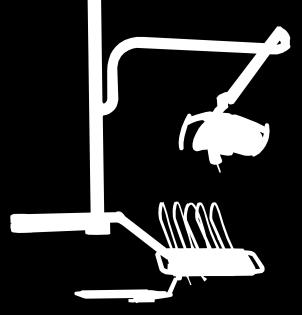
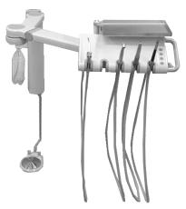
19 Ultrasonic scaler power adjustment Ultrasonic scaler power adjustment Ultrasonic Scaler Water Switch (optional) The hot tip of the ultrasonic scaler may damage the patient's soft tissue and teeth. The tip may also be damaged by heat. Always use cooling water in normal use. The instrument bridge can be equipped with a scaler water control lever. This lever cuts off the water from the ultrasonic scaler. This option is only used in special purposes. 2.6 Suction Head Normally, the suction head holds the suction hose(s), evacuator tips and syringe or other instruments. The instruments are easily reachable and in correct position ready for working. An instrument can be activated simply by picking it up from its holder. Suction head The suction head is connected either to the chair with swivel arms or to the cuspidor with an extendable arm depending of the model. The swivel arms enable a wide movement range of the suction head, which in turn enables wide variety of working positions. No extra weight is intended to be placed on the swivel arms. User Guide 19

20 2.6.1 Suction Head User Interface Key Symbols Function Press briefly action Bowl rinse Rinse bowl for pre-set duration Doorbell Open door Cup fill Fill cup for pre-set duration AUX Activate external relay Positioning the Suction Head To prevent damage to the system, check that there is nothing obstructing the movement of the chair. Locking screw Positioning the suction head The suction head can be adjusted as shown in the above image. The height adjustment (an option) has a locking mechanism, which can be tightened by turning the locking screw. 20 User Guide
.")
21 2.7 Trays Max. 1 kg Instrument tray The tray is used for placing the hand instruments and utensils. Do not place more than 1 kg on the tray. 2.8 Dental Unit The Dental Unit consists of a Cuspidor, an Instrument Bridge, a Display, a Suction Head, a Connection Box, and Tray(s). The maximum total weight of the Dental Unit (without the Connection Box) is 50 kg. User Guide 21

22 2.8.1 Cuspidor Do not open the door of the cuspidor during patient treatment to prevent the risk of electric shock. Cuspidor The cuspidor contains the spittoon bowl with flushing system, cup holder with cup filling system, and suction filters. Separation systems are located inside the cuspidor. Clean water bottle and waste management are also located in the cuspidor. The spittoon bowl is easily detachable.* (*) The maintenance door is optional. If there is no maintenance door, maintenance operations are made by lifting the top of the cuspidor out of way. 22 User Guide

23 2.8.2 Filling the Cup and Rinsing the Bowl To fill the cup, press the button briefly. The cup will be filled up to the pre-set level. To rinse the bowl, press the button briefly. The duration of the rinsing is pre-set. The direction of the rinsing spray may be adjusted by rotating the nozzle of the faucet Water Heater (optional) Heated water is often used with syringes and water injecting instruments. For that reason the system can be delivered with a water heater. The temperature of the water is regulated with a thermostat. Overheating is prevented with a non-reversible thermal cut-out device. If the injected water is cold, please check the position of the button of the thermal cut-out device. The release button is located on the right side of the water heater in the bottom of the cuspidor Clean Water Bottle Use only bottles provided by Fimet Oy. Do not use bottles past their expiry dates. Otherwise there is a possibility that the bottle breaks. Bottle pressure switch on/off Clean water bottle When the switch is turned on, the clean water bottle is pressurized to 1.5 bars and the water for instruments is taken from the bottle. If the bottle is not in use, the water is taken from the water main. The water for cup filling comes either from the clean water bottle or from the water main depending on the desired type of setup. User Guide 23
24 To add water, de-pressurize the bottle by turning the lever to the off-position. The bottle can then be detached safely by rotating it counter clockwise. Do not overfill the bottle; leave at least 2 cm free space on the top. When starting to use the clean water bottle after main water line use, ensure the cleanliness of the water hoses by allowing the water run for a couple of seconds through every instrument, cup filling tap, and cuspidor bowl flushing tap Disinfecting the Water System The clean water bottle can be used to disinfect the instrument hoses and the water tubing. See section 3.1 Cleaning, Disinfecting for more information Daily Use of Mild Disinfecting Solutions Mild disinfecting solutions can be used to prevent contamination coming from main water line and build-up of microfilm. These liquids may be added to the clean water bottle in the right proportion. Please read the manufacturer s instructions for correct usage. 2.9 Connection Box The maximum connection voltage to the relays for the external devices is 24 V. The Connection Box consists of a power supply and connections to drainage, air, mains power, and main water line. The main fuse, the main power switch, and the relays for external devices are also in the connection box. Connection Box is connected to the unit with flexible hoses and electric cables Switching the Device s Power on and off There are harmful voltage levels, pressurized air, and water inside the connection box. Only authorized maintenance staff may open the connection box. Note! When the device is switched on, there are pressurized air and water in the instrument bridge, the suction head, the cuspidor, and the connection box. 24 User Guide
25 Main power switch Main power switch The power of the device is switched on and off with the main power switch. The power switch controls all the electricity in the device. If it is switched off, the device is safe to service. When the power is turned off, the water and air inside the device are depressurized Display & Operating Light The display is not water proof. Avoid getting the system wet when cleaning. Do not look straight into the light. Looking straight at operating light beam may cause damage to eyes. The display can be used with an intra-oral video camera and an external computer. The display must be either: Connected to the F1 power source, or Approved according to the medical device standard IEC The operating light contains its own power switch, which controls the light. Please see the operating light s user guide for detailed instructions. The maximum torque for the pole holding the light is 100 Nm. This equals 10 kg at a distance of one meter or 5 kg at 2 meter distance. The maximum allowed mass of the monitor is 10 kilograms. User Guide 25
26 2.11 Dental Chair Note! To prevent over-heating of motors, the continuous operation of lift and tilt motors is limited. The limiting system is load sensing. With full load, the chair lift and tilt motors operate a shorter time. Double articulated head rest Removable hand rest Adjustable foot rest Chair control panel F1 Chair Chair control panel and remote foot control 26 User Guide
27 Max. 10 kg Total Max. 160 kg (*) Max. 25 kg Maximum supported weight on each part of the F1 Dental Chair The body of the F1 Dental Chair is made of sturdy steel. The design of the compact lift mechanism offers excellent usability to the chair. From its lowest point of 45 cm, the chair moves nearly vertically up to 95 cm. All bearings are pre-lubricated and will seldom require maintenance. All visible parts are injection moulded. The seat, backrest and other parts that are critical to withstanding stress, are reinforced with either steel or plastic body. The maximum allowed torque of the unit attachment is 250 Nm. Maximum allowed mass of the unit is 60 kg. (*)The max mass specified is for chair with no unit attached Motors and Electronics The lift and tilt motors, and the electric circuits of the F1 Dental Chair are of low-voltage type, which reduces the risk of electric shock. A combination of steel and plastic materials is used in the gears of the lift and tilt mechanisms. This structure gives the chair a smooth and quiet ride and ensures a long lifetime of the mechanism. All major components of the F1 Dental Chair are easily accessible for fast and easy maintenance Positioning the Chair Do not sit on the backrest or footrest. It may bend under your weight. User Guide 27


 Joystick Right (push and hold) Instrument Bridge / Suction Head buttons Raise Backrest 1 1 1 1 1 Lower Backrest 2 2 2 2 2 Chair Down 3 3")
28 Beware of damaging the instrument and suction arms when raising or lowering the backrest or the chair. The chair can be operated with several different kinds of controllers. These controllers are: joystick(s), remote foot control, instrument bridge buttons, and suction head buttons. The movement speed of the chair seat and backrest are designed to be adequate, but not fast enough to cause danger to operator or patient. Manual Positioning Function Remote Foot Control Remote Hand Control Joystick Left (push and hold) Joystick Right (push and hold) Instrument Bridge / Suction Head buttons Raise Backrest Lower Backrest Chair Down Chair Up Rotating the Chair and Locking the Position The patient chair can be rotated ±45 after releasing the Chair rotation. 28 User Guide

29 Using Pre-set Positions Do not leave patient/chair unsupervised during the automatic positioning of the patient chair. Some part of the system may be damaged or the patient may be injured. Note! The automatic movement of the chair can be stopped with any chair operating key (1, 2, 3 and 4 keys on instrument bridge, suction head panel, joysticks, remote foot control, and remote hand control) Using Pre-set Positions Remote Foot / Hand Control: Press 5-key / PROG key briefly and after that the desired key within three seconds. Joysticks: Push either one of the chair s joysticks in the desired direction. Instrument Bridge and Suction Head: Press briefly one of buttons 1, 2, 3 or Chair to entry and exit position 2 - Chair to working position 3 - Chair to spitting position 4 - Chair to alternative working position Recalling Pre-set Chair Positions User Guide 29
30 Programming Pre-set Positions Programming Pre-set Positions Position the chair with manual positioning to the desired position. Press the button to start programming. Within three seconds, select the desired memory slot (2, 3 or 4) with the corresponding control from the instrument panel, joystick, remote foot control, or remote hand control. The upper segment of the 7-segment display flashes during the setting time. The memory positions are user-specific. Both users (A and B) can be programmed separately. Please note that position 1 is reserved for entry and exit-position and is pre-set at the factory. It cannot be reprogrammed the normal way. Please contact service personnel to change the default behaviour Selecting the User Chair control panel Pressing the button toggles the selected user between USER A and USER B. The 7- segment display shows a bar to illustrate the selected user. 30 User Guide


31 Extending the Backrest Button for releasing the lock mechanism Backrest from behind To adjust the length of the backrest, first press the button on the backside of the backrest to release the locking mechanism. Then pull or push the backrest to desired length. After adjusting the length, make sure the locking mechanism is locked before starting to use the chair Tilting the Seat and Trendelenburg / Shock Position Knee break release Chair tilting lock Chair rotation lock Mechanical chair controls Headrest Unlocking the chair tilting lock allows the seat, backrest and legrest to be tilted, for setting the legs to a higher position than the head. The headrest is double-articulated and extendable. The locking mechanism locks the headrest to the desired position. Check the tightness of the locking mechanism after adjusting the position of the headrest. The distance between the headrest and the backrest can be adjusted simply by sliding the User Guide 31

32 headrest in or out. Please note that the gap between the headrest and the backrest should be at most 10 cm. The headrest may not be steady enough if elongated too much. The locking lever locks the double articulated movements. Headrest adjustments The movements of the headrest are double-articulated. The headrest can be adjusted around the two axels when the locking lever is in open position. Double-articulated headrest movements Legrest The legrest can be extended (*) and the knee break angle can be adjusted. The legrest moves synchronically with the backrest. (*) Optional 32 User Guide

33 0 Knee break 90 Knee break release Legrest extension (*) Positioning legrest (*) Optional The legrest can be extended simply by pulling the extension part outwards. The knee break can be adjusted from 0 to 90. To lift the legrest, simply just raise it. To lower it, press the knee break release button and lower the legrest. There are three different angles for the knee break. The legrest is positioned synchronically with the backrest Joysticks Joysticks are used to control the movements of the seat and backrest of the chair. The joystick can be moved to four different directions. Joysticks can also be used to position the chair to pre-set positions. Joysticks on the base of the chair Armrests You can turn the armrests and also detach them, if needed. Turning the armrests allows for easy entry and exit for the patients. User Guide 33


34 To turn and/or detach the armrest, lift it slightly to unlock it. After being unlocked, the armrest can be turned. When the armrest has been turned 90, it can be removed completely by lifting it from its holder. 90 Turning and detaching the armrest 2.12 Remote Foot Control Foot Control is used to control the movement of the seat and backrest of the chair, and also to control the instruments. Lift handle Foot control buttons Lever 34 User Guide
35 No instrument selected Key Press briefly Press and hold Pre-set Positioning (activated with 5-key, user predefined position) 1 Raise backrest Raise backrest Chair to entry and exit position 2 Lower backrest Lower backrest Chair to working position 3 Lower chair Lower chair Chair to spitting position and back Chair to alternative working position Raise chair Raise chair 5 Memory Instrument selected 2 1 Key Micro motor Turbine Scaler Curing light 1 Run Run Run 2 Run reverse Run Run 3 Chip blow Chip blow 4 5 Air / Water / Both / Off Select rotation scale Air / Water / Both / Off Foot control operates at 2.4 GHz frequency, which is dedicated for ISM use (industrial, scientific and medical) Recharging the Batteries There are four AA size NiMH rechargeable batteries in the foot control. To recharge the batteries, connect the charging cable to the chair and to the foot control. The connector in the chair is located in the front side of the chair s bottom part. The connector in the foot control is located on the bottom. Recharging time is about 24 hours and charging must be done periodically (in normal use after every months) depending on the operating time. When letter A is displayed in the back panel of the chair, the charge of the batteries in the foot control is low. The system has to be powered on to charge the batteries. The remote control can be operated normally during the charging. The batteries are always charged when the charging cable is connected and the chair is switched on. Overcharging the batteries is not recommended, this will shorten battery lifetime. If the foot control is not to be used for a long time, it is a recommended to remove the batteries from the foot control. When foot control is connected to the chair via the charging cable, the radio communication is stopped and all data is delivered through the charging cable. If there are problems with the radio communication, please connect the charging cable. User Guide 35
36 2.13 Pneumatic Foot Control Instrument water on/off Chip blow Control Pedal Pneumatic Foot Control Air unit instruments are controlled with the pneumatic foot control. This consists of three easy-to-use reliable controls. The user controls the speed of the selected instrument by pressing the pedal. When the pedal is pressed, it supplies air to the instrument thus controlling the speed of rotation. Lever switch is used to select water on/off for the instruments. The Chip blow button releases extra amount of air for selected instrument when pressed rd Party Devices Connecting devices not listed below may cause an electric shock hazard. All devices inside the patient area (within 1.5 m of patient) must be IEC approved. All devices to be connected must be CE marked. All electrically connected devices must be compliant with IEC or/and other applicable IEC standards. The computer must be compliant with either IEC or IEC Compliance with IEC has to be re-evaluated after each modification made to the system. The computer must be powered from its own mains socket. The following types of dental instruments can be connected: Air driven instruments (e.g. turbine) Electric instruments (e.g. micro motor) Curing light Ultrasonic scaler Syringe Amalgam separator Operating light Air/water separator Display Computer connected to the display Video camera External suction systems / motors 36 User Guide
37 2.15 Control Relays for External Devices Relays are used for controlling the external devices. These devices may be, for example, an electric door lock, an external suction motor, a compressor, or doctor reserved light, etc. Maximum connection voltage is 24 V. User Guide 37
38 3 Maintenance and Service Do not treat patients during maintenance or service. 3.1 Cleaning, Disinfecting and Sterilisation Be cautious when using flammable disinfection/cleaning agents because of the risk of fire. Do not smoke or handle fire when handling flammable agents. Always use only products which are designed for the particular task being performed. Follow the product s instructions. Pay especially attention to the disinfection duration of each type of product. Not disinfecting long enough increases the risk of infection while disinfection lasting long may increase the risk of equipment damage Instrument Disinfecting and Sterilisation Using instruments which are not disinfected or sterilised may cause infection hazard to the patient or operator. Follow the instrument manufacturer s instructions on disinfection and sterilisation. All dental instruments that are heat-resistant should be sterilised after each use by steam under pressure (autoclaving), dry heat, or chemical vapour. Before sterilisation or disinfection, instruments must be cleaned of any debris Prior to Treatment Before treatment, make sure there is water and not disinfecting liquid in the clean water bottle Daily Replace silicone covers on the instrument bridge and on the suction head. Used covers are sterilised with an autoclave or disinfected by other suitable means, such as thermal disinfector. All touchable surfaces (including handles, hoses, armrests, and headrest) are disinfected with a suitable cleaning/disinfecting liquid. Instruments are disinfected according to the manufacturer s instructions. Let the water flow through the instruments and cuspidor bowl for at least 3 minutes before treatment of the first patient. 38 User Guide
39 3.1.4 Weekly Display Suction systems must be disinfected or flushed. To disinfect the suction system: Insert the suction hoses to the holes in the side of the cuspidor. Pour the disinfectant liquid into the filling hole. Find the location of the container of the flushing liquid from the pictures of chapter 2.2 System Overview. Wait until the disinfectant liquid has been sucked out. Return the suction hoses to their original positions. Wipe the exterior surfaces of the hoses with a disinfectant. If the cuspidor bowl has been used, it should be cleaned with a suitable solution. Disinfecting waterlines daily is highly recommended. At the end of the day, clean all the surfaces where contamination from secretion is possible using a disinfectant liquid. Clean other surfaces with a suitable detergent. Clean and disinfect the suction system. Artificial leather and genuine leather surfaces must be cleaned with a suitable solution (see Artificial Leather and Leather). Waterlines must be disinfected. All surfaces should be cleaned with a suitable detergent/disinfectant. At the start of work week, let water flow through the instruments for at least 10 minutes before starting treatment. Use cleaning solutions designed for cleaning the displays. To disinfect the display, alcohol based solutions can be used. See the display s user guide for detailed instructions on how to clean and disinfect the display Operating Light See the operating light s user guide for instructions on cleaning the light Secretion Stains All the stains from secretion should be cleaned immediately after the treatment of the patient has finished (chloride-based solutions are suggested, concentration at least 1000 ppm or 1 ) Artificial Leather and Textile Leather Waxing To clean artificial leather and textile surfaces it is suggested to use mildly alkaline (ph 8-10) cleaning solutions. Using alcohol-based solution to disinfect the artificial leather or textile is not suggested, because it may make the material more brittle. To clean genuine leather surfaces, it is suggested to use soap-based cleaning agents that especially intended for cleaning leather surfaces. Do not use acidic or alkaline solutions. Waxing the painted surfaces at least once a year is recommended to keep the surfaces easy to clean. Common car waxes can be used. User Guide 39
40 Flushing of All Instruments After using disinfection solutions, remember to flush the water tubing and instrument hoses with fresh water before treating any patients. Follow the disinfectant liquid manufacturer s instructions. Disinfection liquids containing hydrogen peroxide may reduce the effective operating time of the instrument block s membrane. This function flushes the instrument hoses and instruments with water for a pre-set time. The water is taken from the clean water bottle or from water main. The instruments are placed on a holder, located on top of the cuspidor bowl. Water goes through the water tubing and instruments and flows into to the drain. It is also possible to use a disinfection solution in the bottle. Flush all instruments Flush all instruments switch To start the flushing of all instruments, move the switch to the ON position. Flushing will stop automatically after three minutes or when the switch is returned to the OFF position. 3.2 Servicing and Replacing Filters There is pressurised tubing inside the connection box. Suction filters must be checked regularly and replaced before they are filled with debris and stop functioning properly. The cartridges of the water and air filters inside the Connection Box must be checked and replaced when needed during the annual service. 40 User Guide
41 3.3 Replacing Fuses Warning: High Voltage! The connection box contains mains voltage. Only qualified service personnel may replace the fuses. 3.4 Remote Foot Control Pairing the Foot Control with Instrument Bridge or Patient Chair Attach the other end of the charging cable to the connector on the foot control s bottom plate and the other end to the connector of the instrument bridge or of the chair, depending on which one you want to control. Pairing is done automatically. After this, the charging cable may be detached Pairing the Foot Control with Instrument Bridge and Patient Chair Attach the other end of the charging cable to the connector on the instrument bridge. Press and hold the button 5 on the foot control. Attach the other end of the charging cable to the connector on the foot control. Receiver in the instrument bridge starts to beep. Release the button 5. Before the beeping ends (in 30 seconds), detach the charging cable from the foot control and attach it to the charging connector of the chair. If pairing is successful, the beeping will end immediately. Note! If the beeping stops before successful pairing, perform sections 1 5 again Calibration of the Foot Control Lever Press and hold down button 5 Press chair up and down buttons simultaneously Turn the lever to the 1 and 2 directions a few times. Make sure the lever is turned to its maximum position. Release button Replacing the Batteries Only qualified service personnel are allowed to replace the rechargeable batteries. The replacement batteries must be of type NiMH AA 1.2 V The rechargeable batteries will be replaced every other year during the annual maintenance. If you see leaks in the batteries, ask your maintenance person to replace batteries immediately. User Guide 41
42 3.5 Amalgam Separators, Instruments, Suction Motors, Compressors, and other 3 rd Party Devices Follow the manufacturer s instructions regarding maintenance, disinfection, sterilization, and service (supplied with the device). 3.6 Replacing the Lithium Battery of the Clock Control Card The lithium battery is not replaceable. The clock control card has to be replaced instead of the battery. Only qualified service personnel are allowed to replace the electronic cards 3.7 Clean Water Bottle The clean water bottle must be changed annually to prevent bursting of the bottle due to ageing of material. 3.8 Tightening the Headrest Lock Mechanism The movements of the headrest are double-articulated. The headrest can be adjusted around the two axels when the locking lever is in open position. The tightness of the locking system is adjusted with a plastic tool delivered with the system. Headrest lock mechanism tightening tool Remove the plastic plug on the vertical bar carefully with the chisel end of the tool. Then adjust the tightness of the nut with the key and replace the plug. The plug locks the tightening nut in its place. 3.9 Annual Service Operations Annual service is described in the F1 Technical Manual. Please contact your local retailer or manufacturer to obtain it. 42 User Guide
43 4 Product Information and Safety 4.1 Device Label The device label holds the product name, serial number, the year of manufacture, CEmark and classifications. CE Mark Product Product name Serial number Manufacturer F1 Dental Treatment System Serial No: Fimet Oy Teollisuustie 6 FI Monninkylä Finland Time of manufacture Protection classification of applied parts against electric shock Indication to read operation instructions 4.2 Intended Use Device label This dental treatment system is intended for diagnosis, therapy and dental treatment of persons by properly trained personnel Expected Service Life The expected service life of F1 Dental Treatment system is 10 years. The manufacturer ensures that the System is safe, for at least this period of time, when serviced according to the manufacturer s instructions. In normal conditions, the system is suitable for operation for a longer period of time than this. The manufacturer ensures that spare parts are available at least for this time period Limitations of Use To avoid the risk of fire, this equipment must not be used with flammable anaesthetics. The maximum allowed weight of the patient on the chair with unit attached to it is 135 kg. The maximum allowed weight on the tray is 1 kg. The system is designed to be used at altitudes below 2,000 meters. The electrical safety of the system may be inadequate in altitudes above 2,000 meters. User Guide 43
44 The maximum allowed oxygen level during use is 25%. The system is not designed to be operated in oxygen-rich environments. 4.3 Manufacturer s Guarantee The product comes with a 24-month manufacturer's guarantee starting from the day of purchase. The product must be registered to Fimet Oy. Registration can be done on Fimet s website ( or by filling and returning a correctly filled Registration Form to Fimet. The registration instructions and the registration form are inside the unit manual folder. Guarantee is only valid after successful registration. The end user is responsible for completing registration. The product must be maintained according to the instructions in section 4.5 Maintenance. Third party devices (like instruments and separation systems) are guaranteed by their manufacturer and thus excluded from Fimet Oy s guarantee. Fimet Oy will take care of replacement of faulty device with the manufacturer, if the device was bought from Fimet Oy. Manufacturer s guarantee covers the parts to be replaced, but not the installation work. The guarantee time of the replaced parts is limited to the guarantee period of the product. Manufacturer s guarantee does not cover defects caused by the following: normal wear and tear improper installation, maintenance, repair, care, use, or service of the device, or part of it using non-compliant parts, for example instruments without CE-mark mains power surges, shortages or outages (such as lightning discharges) external causes (for example fires, floods, or vandalism). The manufacturer or the vendor is not responsible for any damage caused by user failing to react to error notifications. 4.4 Installation and Service To avoid the risk of electric shock, this equipment must only be connected to supply mains with protective earth. The installation procedure is described in the F1 Technical Manual. For the warranty to be valid: Installation and service must be carried out by a service provider authorized by Fimet Oy. The safety of the product has to be evaluated after repairs and any modifications according to EN ISO :2006. The product must be serviced according to the schedule defined in section 3.9 Annual Service Operations 4.5 Maintenance Read the section 3 Maintenance to ensure the safe use of the device. 44 User Guide
45 4.6 Classifications and Ratings Type of classification Class Medical Device Directive: IIa (Chair alone: I) Protection against electric Class I shock: Protection against electric Type B shock, applied part: IP classification: IPX0, No special protection IP classification of remote Foot IPX1, protected against dripping water Control: Mode of operation: Continuous (Chair alone: non-continuous) Electrical Rating: 100 V AC, 50/60 Hz, 450 VA (PS150C1/100, PS150C2/100) 110 V AC, 50/60 Hz, 450 VA (PS150C1/110, PS150C2/110) 115 V AC, 50/60 Hz, 450 VA (PS150C1/115, PS150C2/115) 220 V AC, 50/60 Hz, 450 VA (PS150C1/220, PS150C2/220) 230 V AC, 50/60 Hz, 450 VA (PS150C1/230, PS150C2/230) 240 V AC, 50/60 Hz, 450 VA (PS150C1/240, PS150C2/240) 100 V AC, 50/60 Hz, 600 VA (PS2150C1/100, PS2150C2/100) 110 V AC, 50/60 Hz, 600 VA (PS2150C1/110, PS2150C2/110) 115 V AC, 50/60 Hz, 600 VA (PS2150C1/115, PS2150C2/115) 220 V AC, 50/60 Hz, 600 VA (PS2150C1/220, PS2150C2/220) 230 V AC, 50/60 Hz, 600 VA (PS2150C1/230, PS2150C2/230) 240 V AC, 50/60 Hz, 600 VA (PS2150C1/240, PS2150C2/240) 4.7 Information about Electromagnetic Compatibility The information in this chapter has to be considered when installing and using the F1 product family. Portable and mobile RF communications equipment, for example mobile phones, can affect the functionality of F1 products. Guidance and manufacturer s declaration electromagnetic emissions The F1 products are intended to be used in the electromagnetic environment specified below. The customer or the user of the F1 product should assure that it is used in such an environment. Emissions test Compliance Electromagnetic environment guidance RF emissions CISPR 11 RF emissions CISPR 11 Harmonic emissions IEC Voltage fluctuations/ flicker emissions IEC Group 1 Class B Class A Compliant The F1 products use RF energy only for its internal function. Therefore, its RF emissions are very low and are not likely to cause interference in nearby electronic equipment. The F1 products are suitable for use in all establishments, including domestic establishments and those directly connected to the public low-voltage power supply network that supply buildings used for domestic purposes. User Guide 45
Foot control. No instrument selected. A Raise chair Chair to working position 1 B Incline backrest Chair to spitting. positioning
 Quick guide Foot No instrument selected Key Press briefly Preset ing A Raise chair Chair to working 1 B Incline backrest Chair to spitting C Lower chair Chair to entry and exit D Decline backrest Chair
Dental Unit User's Guide
 Dental Unit User's Guide MDD 93/42/EEC May 1999 8200590 Quint-7000 User's Guide We reserve the right to make changes. Manufactured by: FINNDENT OY Teollisuustie 5 FIN-07230 MONNINKYLÄ Tel. +358 19 5221500
Dynamics Precision Speed
 English FD-8000 Dental Units Vol. 07/2014 Dynamics Precision Speed 8000B floor units are known for reliability and style. The possibilities are endless, with several options for suction, cuspidor, amalgam
FOR YOU AND YOUR CUSTOMER
 FOR YOU AND YOUR CUSTOMER ELEGANT AND COMPACT DESIGN The ergonomic and elegant design of the Fimet Neo dental treatment unit makes your practise more functional and convenient than ever before. The Neo
CHIRANA Medical, a. s.
 CHIRANA Medical, a. s. Námestie Dr. A. Schweitzera 194 916 01 Stará Turá Slovak Republic tel.: +421 (32) 775 2257 fax: +421 (32) 775 2218 e-mail: medical@chirana.eu www.chirana.eu Registered trade marks:
Table of Contents. English
 OM-E0799E 000 English Thank you for purchasing VIVA ace Motor Kit. Please read this Operation Manual and the VIVA ace Basic Set Operation Manual carefully before use for operating instructions and care
Planmeca Sovereign Classic
 KI Page 1(25) Planmeca Sovereign Classic Planmeca Sovereign Classic dental unit is the perfect outcome of clever design details that facilitate your work throughout the day. From patient treatment to easy
FIMET F1 DENTAL EQUIPMENT
 FIMET F DENTAL EQUIPMENT FIMET R0000 Hose carrier assembly kit R00 Hose carrier R00 Hose carrier fixing pieces with screw R00 Hose carrier spring R00 Bearing R0 Hose cover RBIT Holder tube R00 Handle R0
ASPIRE Laboratory Aspirator
 ASPIRE Laboratory Aspirator USER MANUAL Rev 2/14/18 Accuris Instruments / Benchmark Scientific Ph: (908) 769-5555 E-mail: info@accuris-usa.com (C) Benchmark Scientific, 2018 THE ACCURIS ASPIRE LABORATORY
Unlimited Mobility. The Mobile Dental Units From. B-Productions
 Unlimited Mobility The Mobile Dental Units From B-Productions Mobile Units from B-Productions: Unlimited Mobility in elegant stainless steel DENTA-PORT 303 Specifications» Portable: Treat your patients
Flexibility and individual design turn your dental unit into an active partner. Quality is not a consideration quality is the solution
 X X Flexibility and individual design turn your dental unit into an active partner Quality is not a consideration quality is the solution 2 3 Complete control - with the foot Leave the possibilities open
AS Medizintechnik GmbH Sattlerstrasse 15, Tuttlingen, Germany Tel 07461/ Fax 07461/
 General Information Use The Air drill System is a pneumatic powered system used for many applications orthopedic and trauma surgery. To ensure proper operation of the air drill, use only original attachment
DENTAL UNIT. Rod Type OPERATING INSTRUCTIONS
 DENTAL UNIT Rod Type OPERATING INSTRUCTIONS IMPORTANT This manual provides operating instruction for CLESTA II ROD TYPE. The instructions contained in this booklet should be thoroughly read and understood
Instructions for use. BA Optima. Air motors BA602 (BA640081) BA604 (BA640060)
 BA604 (BA640060)") Instructions for use BA Optima Air motors BA602 (BA640081) BA604 (BA640060) Contents 1. Introduction....3 5 2. Safety notes...6 9 3. Product description... 10 11 4. Operation... 12 13 Assembly/Removal,
Instructions for use BA Optima Air motors BA602 (BA640081) BA604 (BA640060) Contents 1. Introduction....3 5 2. Safety notes...6 9 3. Product description... 10 11 4. Operation... 12 13 Assembly/Removal,
Operating / User Manual
 UniARM Surgical Support System Operating / User Manual Version 1.1 MITAKA KOHKI Co., Ltd. 1. Introduction Introduction Thank you for purchasing the UniARM for use in surgical procedures. To use the device
Dyna-Form Air. Alternating Pressure Relief Overlay System
 Dyna-Form Air Alternating Pressure Relief Overlay System 1 Contents Introduction 3 Cleaning 10 General Warnings 4 Control Unit 10 Unpacking / Setting Up 5 Air Filter 10 Setting Up 6 Mattress Cover 11 Connect
UL U TR LTRASONIC S ONIC SCALE ALER PIEZO MINI
 ULTRASONIC SCALER PIEZO MINI CONTENTS XI - SYMBOLS 1. INTRODUCTION 1 Alternating current Type BF device 2. WARNINGS 1 3. PRESENTATION 1 3.1 Presentation 1 3.2 Technical description 2! Warning, please refer
Care instructions ESTETICA E80. Always be on the safe side.
 Care instructions ESTETICA E80 Always be on the safe side. Distributed by: KaVo Dental GmbH Bismarckring 39 D-88400 Biberach Tel. +49 7351 56-0 Fax +49 7351 56-1488 Manufacturer: Kaltenbach & Voigt GmbH
Unlimited Mobility The Mobile Dental Units By. BPR Swiss
 Unlimited Mobility The Mobile Dental Units By Product Overview The world of mobile dental carts: The world of portable plug-and-play dental units: The world of portable dental units: The world of portable
OPERATING INSTRUCTIONS
 H DENTAL UNIT BOOK NO. 1E03D2C0 (3E) Printed in JAPAN. 2014-07 OPERATING INSTRUCTIONS Thank you for purchasing TAKARA BELMONT product. Please read through this instruction manual carefully before using
5. Instrument and accessories discharging must be done following current law regulations in every country of use.
 VEGA it s a device working 230V ~ / 50 Hz network electricity, to be used for the nasal aspiration, oral aspiration, tracheal aspiration of the body liquids (mucus, catarrh or blood) in the adult or in
Contents. English. English
 OM-E0798E 000 Thank you for purchasing VIVA ace Basic Set. This product is a Portable Dental Treatment Unit used for on-site patient treatment. Please read this Operation Manual carefully before use so
X99 Series. Dental Handpiece. Instruction For Use
 X99 Series Dental Handpiece Instruction For Use 0413 Table of Contents Symbols... 2 Introduction... 3-4 Before Use... 5 Product description... 6 Technical Specifications... 7 Operation... 8-11 Hygienic
OPERATION and MAINTENANCE INSTRUCTION MANUAL. ADU-12 Task Force Pneumatic Portable Dental System
 OPERATION and MAINTENANCE INSTRUCTION MANUAL ADU-12 Task Force Pneumatic Portable Dental System TABLE OF CONTENTS: Package Contents....................1 Introduction.........................2 Setting Up
FONA DURION Dental unit operation instruction
 Dental unit operation instruction Index 1. General information... 5 General information on the Operation Instructions... 5 Scope of these Operation Instructions... 5 Other valid documents... 5 Warranty
PORTABLE ICE MAKER. Model: IM-124S INSTRUCTION MANUAL
 PORTABLE ICE MAKER Model: IM-124S INSTRUCTION MANUAL It is important that you read these instructions before using your portable ice maker and we strongly recommend that you keep them in a safe place for
Care instructions. Primus 1058 Life
 Care instructions Primus 1058 Life Manufacturer: Kaltenbach & Voigt GmbH Bismarckring 39 D-88400 Biberach www.kavo.com Distributed by: KaVo Dental GmbH Bismarckring 39 D-88400 Biberach Phone +49 (0) 7351
Installation and Operating Instructions DÜRR Regeneration Unit for X-ray developers XR 24, XR24 II, XR 24 Nova, XR 24 Pro
 Installation and Operating Instructions DÜRR Regeneration Unit for X-ray developers XR 24, XR24 II, XR 24 Nova, XR 24 Pro 2006/01 Content Important Information 1. Notes... 3 1.1 CE - Labeling... 3 1.2
XO FLEX User Manual 2
 XO FLEX USER MANUAL XO FLEX User Manual 2 XO FLEX User Manual Table of contents CONTENTS 1 EXTRAORDINARY DENTISTRY... 7 2 Symbols... 8 3 Operation... 9 3.1 General... 9 3.2 Arm systems... 11 3.3 Hand instrument
Instructions for use / Alarm unit, Fiber optic cable & Sensor patch ENGLISH
 Instructions for use / Alarm unit, Fiber optic cable & Sensor patch ENGLISH Manufacturer: Redsense Medical AB Gyllenhammars väg 26 302 92 HALMSTAD SWEDEN www.redsensemedical.com These instructions are
DEKO 190 Ward washer-disinfector
 DEKO 190 Ward washer-disinfector SUPERIOR PERFORMANCE, LARGE CAPACITY AND ADVANCED STATE-OF-THE-ART CONTROL DEKO 190 The DEKO 190 is designed and constructed to exceed the standard performance and design
ULTRASONIC HUMIDIFIER
 To Buy: Visit www.sylvane.com or call (800) 934-9194 For Product Support: Contact Sunpentown at 1-800-330-0388 ULTRASONIC HUMIDIFIER [ADORABLE MONKEY] To prolong the life of this humidifier, using distilled
1 Intended Use of the Breas HA 01 Humidifier
 User Manual for Breas HA 01 Humidifier 1 Intended Use of the Breas HA 01 Humidifier Read this manual thoroughly so that you completely understand how the humidifier is operated and maintained before taking
MaxiCompressor. Limited Warranty. High Performance 50 PSI Compressor 501-S
 Limited Warranty Global Medical Holdings (GMH) warrants the MaxiCompressor for 1 year from the date of purchase due to faulty parts or workmanship. This warranty is limited to the original purchaser of
INSTRUCTION / INSTALLATION / TECHNICAL MANUAL
 Suntem INSTRUCTION / INSTALLATION / TECHNICAL MANUAL ADAPTABLE MODEL: ST-D520 ST-D530 ST-D540 Thank you for purchasing the dental therapy unit produced by our company. Please read this manual carefully
Honeywell. Wireless Rain Gauge with Indoor. Temperature (TC152) USER MANUAL TABLE OF CONTENTS INTRODUCTION 3 PRODUCT OVERVIEW 4 REMOTE RAIN GAUGE 7
 USER MANUAL TABLE OF CONTENTS INTRODUCTION 3 PRODUCT OVERVIEW 4 REMOTE RAIN GAUGE 7") TABLE OF CONTENTS INTRODUCTION 3 PRODUCT OVERVIEW 4 REMOTE RAIN GAUGE 7 BEFORE YOU BEGIN 9 BATTERY INSTALLATION 10 LOW BATTERY WARNING 11 HOW TO USE THE TABLE STAND 11 GETTING STARTED 11 Honeywell Wireless
TABLE OF CONTENTS INTRODUCTION 3 PRODUCT OVERVIEW 4 REMOTE RAIN GAUGE 7 BEFORE YOU BEGIN 9 BATTERY INSTALLATION 10 LOW BATTERY WARNING 11 HOW TO USE THE TABLE STAND 11 GETTING STARTED 11 Honeywell Wireless
OPERATING INSTRUCTIONS
 DENTAL UNIT AND CHAIR OPERATING INSTRUCTIONS IMPORTANT This manual provides operating instructions for VOYAGER II. The instructions contained in this booklet should be thoroughly read and understood before
OPERATING INSTRUCTIONS
 DENTAL UNIT AND CHAIR OPERATING INSTRUCTIONS IMPORTANT This manual provides operating instructions for VOYAGER-II L. The instructions contained in this booklet should be thoroughly read and understood
JASOPELS ROTATING FLESHING MACHINE 1-BEAM
 USER MANUAL JASOPELS ROTATING FLESHING MACHINE 1-BEAM ITEM NO. 32200067 Our quality Your choice 2 www.jasopels.com TABLE OF CONTENTS About this document... 3 Declaration of Conformity... 6 Safety... 6
*smith&nephew VERSAJET HYDROSURGERY SYSTEM
 Product Manual Manuel D utilisation Bedienungshandbuch Manual Del Producto Manuale Prodotto Producthandleiding *smith&nephew VERSAJET HYDROSURGERY SYSTEM VERSAJET Hydrosurgery System Product Manual Contents
Short instructions for use ESTETICA E30
 Short instructions for use ESTETICA E30 Distributed by: KaVo Dental GmbH Bismarckring 39 D-88400 Biberach Tel. +49 7351 56-0 Fax +49 7351 56-1488 Manufacturer: Kaltenbach & Voigt GmbH Bismarckring 39 D-88400
OPERATION and MAINTENANCE INSTRUCTION MANUAL. ADU-20B CompriCart
 OPERATION and MAINTENANCE INSTRUCTION MANUAL ADU-20B CompriCart TABLE OF CONTENTS: Introduction.........................1 Package Contents....................1 Setting Up the Unit...................2 -
Operator s Manual. Model G32-S Model G32-E Disinfection Soak Stations
 Model G32-S Model G32-E Disinfection Soak Stations Operator s Manual CIVCO Medical Solutions 102 First Street South Kalona, IA 52247 USA Tel: 1-800-445-6741 Fax: 1-877-329-2482 Website: WWW.CIVCO.COM Copyright
EL400 OPERATION MANUAL
 All Titanium Body Micromotor System EL400 OPERATION MANUAL 40,000min -1 (rpm) OM-E0078E Rev.3 Please read this operation manual carefully before use and keep for future reference. Classification of equipment
Enhance DX. Mattress Replacement System. User Manual
 Enhance DX Mattress Replacement System User Manual Prius Healthcare USA 580 Corporate Center 4025 Tampa Road, #1117 Oldsmar, FL 34677, USA TEL: (813)854-5464 FAX: (813)854-5442 1111 Content 1. THE PURPOSE
VIVA ace Quick Operation Guide
 VIVA ace Quick Operation Guide Contents 1. Installing the Holder Bar and Arm...2 2. Connecting the Motor, the Scaler, and the Syringe...3 3. Installing the Vacuum...4 4. Installing the Water Bottle...5
OPERATION AND MAINTENANCE MANUAL
 OPERATION AND MAINTENANCE MANUAL ADU-10CF (NSN: 6520-01-456-7170) Part 1 of 2 P.O. Box 1548 Woodinville, WA 98072-1548 1-800-426-5913 * 425-487-3157 * Fax: 425-487-2608 email: info@aseptico.com * Internet:
Congratulations on your Alert- it purchase
 Congratulations on your Alert- it purchase Your product has been manufactured by a team of industry experts with more than 20 years of experience designing, manufacturing and distributing care alarms.
Operating Manual for Profident / Profident PLUS
 Operating Manual for Profident / Profident PLUS Content: 1. Accessories... 1 2. First Steps... 2 2.1 Air Pressure... 2 2.2 Positioning of the Handpieces... 2 2.3 Pressurised Water Bottle... 3 2.3.1 Refill
PRESSURE WASHER MODEL NO: JETSTAR 1750 OPERATION & MAINTENANCE INSTRUCTIONS. WARNING Read the instructions before using the machine PART NO:
 WARNING Read the instructions before using the machine PRESSURE WASHER MODEL NO: JETSTAR 1750 PART NO: 7333230 OPERATION & MAINTENANCE INSTRUCTIONS LS0711 INTRODUCTION Thank you for purchasing this CLARKE
Wireless Rain Gauge with Indoor Temperature
 TABLE OF CONTENTS INTRODUCTION 3 PRODUCT OVERVIEW 4 7 BEFORE YOU BEGIN 9 BATTERY INSTALLATION 10 Wireless Rain Gauge with Indoor Temperature LOW BATTERY WARNING 11 HOW TO USE THE TABLE STAND 11 GETTING
Instruction Cum User Manual For EUROLITE
 An ISO 9001:2008, 13485: 2012 Certified Company Instruction Cum User Manual Bacterial Filter Vacuum Gauge Connector for Patient use Float Valve Hi/Low Switch On/Off Switch Vacuum Control Knob 1 Ltr PC
CLETEF-786. Infrared Thermometer Instruction Manual
 CLETEF-786 0482 Infrared Thermometer Instruction Manual Introduction Thank you for choosing the Clever Choice Duo TM Ear & Forehead Thermometer, by Simple Diagnostics. The infrared thermometer CLETEF-786
Before using your machine, you must familiarize yourself with all of its components.
 USE AND MAINTENANCE MANUAL FOR THE FOAMTEC 1800 NOTE: As with all electrical equipment, care and attention must be exercised at all times during its use, in addition to ensure that routine and preventative
Veterinary Patient Warming System Controller User Manual
 Veterinary Patient Warming System Controller User Manual Contents Introduction... 3 Indications for use... 3 Contraindications... 3 Warnings... 3 Precautions... 4 Proper Use and Maintenance... 5 Initial
HG 675 CX 60 HG 675 CN 60 HG 675 CW 60
 HG 675 X 60 HG 675 CX 60 HG 675 CN 60 HG 675 CW 60 1 2 1. : 93/68: 90/396: 2006/95/CE: 2004/108/CE: - 1935/2004:. 2002/95/CE: RoHS 2.,.,,,,...,. (,..)..,,.,. ( ),,, ;,,.,.....,.,,,,,,...,. (..),,.,..,.,,,,
PROGRAMMABLE 7-DAY RF THERMOSTAT
 PROGRAMMABLE 7-DAY RF THERMOSTAT Installation and user instruction This instructions to be retained by the user 1 Thank you for choosing Beretta s radio frequency (RF) Radiostat. This central heating control
Purity. Quality. Lightness.
 Purity. Quality. Lightness. Designed to last FD-8000 Dental Units QUALITY The Finndent 8000 product family is the result of 30 years of dental unit development. Proven and field-tested technology combines
User Manual WMF Cup&Cool WMF Cup
 coffee wakes up the world User Manual WMF Cup&Cool WMF Cup Add-on Equipment English bistro! 2000S presto! 1400 prestolino! 1300 Model Series 9018 / 9019 Order Nr. 33 0916 1000 Edition 04.2010 General Information
Classic Twelve O clock Cabinet Installation Instructions
 Classic Twelve O clock Cabinet Installation Instructions CF36 CF42 THIS MANUAL IS FOR AUTHORIZED AND QUALIFIED INSTALLATION PERSONEL ONLY! Table of Contents General Information... 3 CF36 Cabinet Overview...
Tornado Operations & Maintenance Manual
 TORNADO INDUSTRIES 7401 W. LAWRENCE AVENUE CHICAGO, IL 60706 (708) 867-5100 FAX (708) 867-6968 www.tornadovac.com Tornado Operations & Maintenance Manual MODEL NO. 99690 BD 22/14, 99720 BD 26/14 L9722
One-Touch Dispense. Multi-temp selections. 208 F For tea, coffee, instant noodle. 194 F Keep warm around 194 F. 176 F Keep warm around 176 F.
 Instruction Manual Automatic Dispensing Hot Water Pot with Multi-temperature Function Automatic Dispensing One-Touch Dispense FEATURES Reboil Function 5 Temperature Settings Image Of SP-5016 208 F For
Instruction Manual. Self-Leveling Combination Cross-Line Laser and Five-Beam Laser Dot Model No &
 6339H_Manuals 10/24/12 12:56 PM Page 1 Self-Leveling Combination Cross-Line Laser and Five-Beam Laser Dot Model No. 40-6685 & 40-6687 Instruction Manual Congratulations on your choice of this Self-Leveling
Instruction Manual. Self-Leveling Combination Cross-Line Laser and Five-Beam Laser Dot Model No , &
 1622i_Manuals 12/14/16 12:52 PM Page 1 Self-Leveling Combination Cross-Line Laser and Five-Beam Laser Dot Model No. 40-6685, 40-6687 & 40-6688 Instruction Manual Congratulations on your choice of this
TRIO Rx. Portable Ultra- High FAC Decanter Activator Set Instruction Manual
 TRIO Rx Portable Ultra- High FAC Decanter Activator Set Instruction Manual Point of use production of activated cleaner and sanitizer/disinfectant Environmentally responsible Effective on hard surfaces
... take a seat. Ritter made in germany
 ... take a seat. Ritter made in germany Dental Units platinum line Contact World H/HC/S/C PINK line Contact Lite Comfort H/HC/S/C Aria SR/Aria SR Smart gold line ULTRA Performance E, H/S ULTRA Performance
ULTRASONIC HUMIDIFIER With Night Light and Fragrance Diffuser
 To Buy: Visit sylvane.com or call (800) 934-9194 For Product Support: Contact Sunpentown 1-800-330-0388 ULTRASONIC HUMIDIFIER With Night Light and Fragrance Diffuser SU-2550B (Blue) SU-2550P (Pink) SU-2550V
MODEL 7000 SUCTION UNIT
 MODEL 7000 SUCTION UNIT OPERATOR S MANUAL Caution Federal law restricts this device to sale by or on order of a physician, or any other practitioner licensed by the law of the State in which he practices
User Manual. Non-contact Infrared Thermometer.
 User Manual Non-contact Infrared Thermometer www.paryvara.com info@paryvara.com Introduction Thank you for purchasing this Non-contact Infrared Thermometer. Please read the User Manual carefully to ensure
User Manual J841Q. Magnetostrictive Scaler / Polisher Combo Unit. Jorgensen Laboratories Tel: Fax:
 User Manual J841Q Magnetostrictive Scaler / Polisher Combo Unit Jorgensen Laboratories Tel: 800-525-5614 Fax: 970-663-5042 Email: jortech@jorvet.com 1 Warnings Important Notes! The equipment is only to
DEKO 25 washer-disinfector
 DEKO 25 washer-disinfector DEKO 25 The DEKO 25 has been designed to bring reliability, outstanding cleaning and disinfection performance and quality into one compact and economic washer-disinfector. It
Tornado Operations & Maintenance Manual
 Tornado Industries, LLC 333 Charles Court West Chicago, IL 60185 www.tornadovac.com Tornado Operations & Maintenance Manual MODEL NO. 99414 Form No. L9740AB Tornado Industries, LLC. All rights reserved
SERRES SUCTION BAG SYSTEM MANUAL
 SERRES SUCTION BAG SYSTEM MANUAL INSTRUCTIONS FOR USE Please read this manual carefully before installing or using the Serres Suction Bag System. A B C 1 C6 C4 C5 C2 C1 C3 3.1 3.2 1 2 3 3.3 3.4 2.1 2.2
INSTALLATION MANUAL GUTHD2. Universal Two Way Digital Thermostatic Valve for Shower Systems
 INSTALLATION MANUAL GUTHD2 Universal Two Way Digital Thermostatic Valve for Shower Systems IMPORTANT: To ensure this product is installed properly, you must read and follow these guidelines. The owner/
Refrigerated Incubator Model and Operating Instructions
 Refrigerated Incubator Model 165000 and 165000-2 Operating Instructions N2400379 - Rev. 1 08May2018 1 Contents 1. SAFETY...3 1.1. EMF INTERFERENCE...4 1. PRODUCT INFORMATION...5 1.1 INTRODUCTION...5 2.
RELIABILITY AND TECHNOLOGY, SUITABLE FOR EVERY STYLE. MIGLIONICO.NET
 RELIABILITY AND TECHNOLOGY, SUITABLE FOR EVERY STYLE. MIGLIONICO.NET RELIABILITY AND TECHNOLOGY, SUITABLE FOR EVERY STYLE. Technology at the service of functionality and security. Simple and versatile
REGISTER YOUR PRODUCT. for warranty claims INSTALLATION PROOF. Please complete and return
 REGISTER YOUR PRODUCT for warranty claims INSTALLATION PROOF Please complete and return Fax: 305 662 7479 E-mail: pwd@metasys.com Dealer Date For the dental office: Please confirm that your technician
SERIES 4000 AUTO GATE MANUAL
 SERIES 4000 AUTO GATE MANUAL Website: www.turnstilesecurity.com Page 1 of 27 Table of Contents 1.0 Warranty... 4 2.0 Safety... 5 2.1 Designated Use... 5 2.2 Areas of Application... 5 2.3 Warning Notes...
Instructions for use. 301 plus
 Instructions for use 301 plus Contents W&H symbols... 3 1. Introduction...4 5 2. Unpacking... 6 3. Package contents... 7 4. Safety precautions... 8 5. Description of the front side... 9 6. Description
Mira Platinum Wireless Controller
 Mira Platinum Wireless Controller These instructions must be left with the user User Guide 1 1105041-W2-H CONTENTS Introduction...3 General...3 Safety Information...3 Control Layout...4 Display Symbols...5
KHM800 Professional 800w haze machine
 KHM800 Professional 800w haze machine M A N U A L V E R S I O N 2. 0 0 6-1 1-1 2 Due to continuous product development, please ensure that you have downloaded the latest instruction manual for this product
SOUND-INSULATED FAN. Iso-K OPERATION MANUAL. Iso-K_v.1(2)-EN.indd :20:59
-EN.indd :20:59") SOUND-INSULATED FAN OPERATION MANUAL _v.1(2)-en.indd 1 10.08.2015 15:20:59 CONTENT Introduction 3 General 3 Safety rules 3 Transport and storage requirements 3 Manufacturer's warranty 3 Fan design 4 Delivery
SOUND-INSULATED FAN OPERATION MANUAL _v.1(2)-en.indd 1 10.08.2015 15:20:59 CONTENT Introduction 3 General 3 Safety rules 3 Transport and storage requirements 3 Manufacturer's warranty 3 Fan design 4 Delivery
Manual Page 1 of 8. Manual. Laboratory autoclave
 Manual 17.11.2014 Page 1 of 8 Manual Laboratory autoclave Autoclave using steam for the treatment of material and laboratory processes e.g. sterilization, as an aid in research and development CertoClav
AA Z** V2** W** U1* V** U2** USER MANUAL U* E D L U3* M N S ** T* O Q P P3 P2 P1 R** AD* PRINTED IN P.R.C /01
 AA Z** V2** H F Y* G AB X* I J AC W** U1* C B A K V** U2** USER MANUAL U* E D L U3* M N S ** T* O PRINTED IN P.R.C. 48022156/01 Q P P3 P2 P1 R** AD* *Certain models only **May vary according to the model
Installation Instructions. Mira LED Light System
 Installation Instructions Mira LED Light System w w w. a m i c o. c o m Contents Symbols Used in This Manual 4 Safety Instructions 5 Variants 7 Scope Of Delivery 8 Installing Mira LED Ceiling Mounted Installing
Mira Platinum Wireless Controller
 Mira Platinum Wireless Controller These instructions must be left with the user User Guide 1 CONTENTS Introduction...3 General...3 Safety Information...3 Control Layout...4 Display Symbols...5 Using the
DEKO 260 Washer - Disinfector - Dryer
 DEKO 260 Washer - Disinfector - Dryer HIGH QUALITY, EFFICIENT WASHING PERFORMANCE WITH SHORT CYCLE TIMES DEKO 260 The Deko 260 washerdisinfector-dryer is designed and manufactured to be fully compliant
Suzhou VICTOR Medical Equipment Co., Ltd
 Suzhou VICTOR Medical Equipment Co., Ltd TYPE:COMPUTER CONTROLLED INTEGRAL DENTAL UNIT: VM2000 Factory configuration: 1: full computer control, mute the low-voltage DC motor drive 2:180 degree swivel and
Dry Bath Heating Systems
 Dry Bath Heating Systems Instruction Manual N2400-4001 Dry Bath Heating System, Single Block, Digital N2400-4002 Dry Bath Heating System, Dual Block, Digital www.starlabgroup.com DECLARATION OF CONFORMITY
Short instructions for use ESTETICA E30
 Short instructions for use ESTETICA E30 Distributed by: KaVo Dental GmbH Bismarckring 39 D-88400 Biberach Phone +49 (0) 7351 56-0 Fax +49 (0) 7351 56-1488 Manufacturer: Kaltenbach & Voigt GmbH Bismarckring
Mobile Air Conditioner Instruction Manual Model TC-N9KM
 Mobile Air Conditioner Instruction Manual Model TC-N9KM Please read and retain these instructions for future reference SPECIFICATION Model no. Cooling capacity Power/Ampere consumption for cooling* Air
ANCAR 3200 USER MANUAL
 ANCAR 3200 USER MANUAL Antoni Carles, S.A. Volta dels Garrofers, 41-42 Pol. Ind. Els Garrofers 08340-Vilassar de Mar (Barcelona-SPAIN) T. (34) 93 754 07 97 F. (34) 93 759 26 04 calidad@ancar-online.com
SAFETY AND OPERATING MANUAL. Original instructions 2000W WALLPAPER STRIPPER
 24 SAFETY AND OPERATING MANUAL Original instructions This appliance can be used by children aged from 8 years and above and persons with reduced physical, sensory or mental capabilities or lack of experience
2364 Leicester Road, P.O. Box 175, Leicester, NY Phone (585) Fax (585)
 Fax (585)") Dry Heat Sterilizers with 60 Minute Sterilization Cycle Times MODEL 3100 MODEL 2100 2364 Leicester Road, P.O. Box 175, Leicester, NY 14481 Phone (585) 382-3223 Fax (585) 382-9481 www.cpac.com December
Dry Heat Sterilizers with 60 Minute Sterilization Cycle Times MODEL 3100 MODEL 2100 2364 Leicester Road, P.O. Box 175, Leicester, NY 14481 Phone (585) 382-3223 Fax (585) 382-9481 www.cpac.com December
TCB-IFTH1GUL. 24V Thermostat Interface. Installation Manual. Model name: English FOR INSTALLER
 24V Thermostat Interface Model name: TCB-IFTH1GUL FOR INSTALLER Read this manual before using the TCB- IFTH1GUL 24V Thermostat Interface. Refer to installation manuals supplied with Indoor Unit, Remote
Manual Pre-disinfection/Cleaning and Sterilization Instructions for SATELEC Tips and Files
 Manual Pre-disinfection/Cleaning and Sterilization Instructions for SATELEC Tips and Files Cautions Do not use steel wool or abrasive cleaners. Avoid solutions containing iodine or with a high chlorine
A measured step forward
 A measured step forward Operations & Maintenance Manual TM JESCO UV 405-412-440-450-480-550-80 2 LCD LCD PLUS Contents 1. Introduction...3 2. General Principles and Safety Instructions...4 3. Instructions
USER MANUAL. Intelligent toilet Primus
 USER MANUAL Intelligent toilet Primus Thank you for your trust. We really appreciate your purchase of AXENT products. Before using the products, please read this user manual to ensure safe and proper
Table of Contents What to Expect with Your Installation. Tools Needed. Motor Housing.
 Table of Contents Congratulations on purchasing your new Casablanca ceiling fan! It will provide comfort and performance in your home or office for many years. This installation and operation manual contains
Operations Manual. Part Number: For Research Use Only
 Operations Manual Part Number: 470230-598 For Research Use Only Ph: 1-800-962-2660 - Web: www.wardsci.com Thank you for choosing our Bench top sterilizers. Prior to operating this instrument, please read