DC INVERTER AIR TO WATER HEAT PUMP AC series Heating & Cooling series CX45
|
|
|
- Dwight Owens
- 5 years ago
- Views:
Transcription

1 DC INVERTER AIR TO WATER HEAT PUMP AC series Heating & Cooling series CX45 Installation and Operation Manual Version 1 1
2 Table of Contents Safety Precautions... 3 Components... 4 Hydronic piping and design guide... 5 ` Heat Pump Installation Electrical Connections System Filling Control Panel Parameter Checking and Setting Parameter Checking Only Display Modes Controller Communications Fuction Selection switch Error Codes Test Run


3 Safety Precautions NOTE: It is required to read the Safety precautions in detail before operation. The precautions listed below are very important for safety, please follow all safety precautions. General Make sure that the ground wire in the building is securely connected to earth. Wiring tasks should be carried out by qualified electricians only, in addition, they should check the safety conditions of power utilization, for example, verify that the line capacity is adequate, and the power cable isn t damaged. Users must not install, repair or relocate the unit. Improper procedures might lead to accidents e.g. personal injury caused by fire, electrical shock or unit's falling off its base, and water leaking into the machine. Please contact a professional service department if problems arise. The unit shall not be installed at a spot with the potential hazard of leaking flammable gas. If gas is leaking near the machine, there might be the risk of explosion. Make sure that the foundation of the unit is stable. If the foundation is unstable, the outdoor unit may come loose from its base and cause injury. Make sure that the GFCI installed at the service panel is working properly to avoid shock or fires. If any abnormity occurs in the unit (such as a burning smell is noticed inside the unit), cut off the power supply immediately, and contact a professional service department. Please observe the follow items when cleaning the unit. Before cleaning, shut off the electric supply of the unit first to avoid injuries caused by the fan operation. Do not rinse the unit with water because the rinsed unit may cause electric shock. Make sure to shut off the electric supply before maintaining the unit. Please do not insert fingers or sticks into air outlet or air inlet. Transporting and storage The machine must be transported and stored vertically. Components 3

4 4
5 Hydronic Piping and Design Guide Installation Methods Heating and Cooling (Heating Shown) Typical Reverse Return Piping No Buffer Tank Installation Notes: 1. Minimum pipe size should be no less than 1, CPVC or PEX, reverse return piping is preferable to eliminate balancing valves or pressure regulators. The installer should calculate the pipe and fitting resistance to determine the head pressure. See the examples on the following pages, maximum water flow for the CX30 is 6 gpm, design flow is 4.8 gpm. If necessary, a larger PWM pump may be added to the loop and controlled by the CX30. The second water pump connections can be found in the wiring diagram. 2. The loop example above is designed with wild coils. Water flows through the coil at all times, if there is a call for heating or cooling the FCU controls will turn the fan on. Optionally, a 2 way valve may be installed at the input tee to prevent any flow through the coil and the FCU will control it. 3. An air discharge valve should be installed at the top of the circulation system if possible for easy air discharge. As an alternative an automatic/manual air vent can be used inline before the pumps. 4. Flow meters with restrictor valves, Watts FlowGuard for example, may be used when reverse return piping is not an option. 5. Always install a water filter or wye strainer on the supply pipe to the chiller to prevent blockage of the heat exchanger. 5
6 Piping Examples: Stacked Chillers With a Buffer Tank and Second Non-PWM Pump A Buffer tank should be used if the total loop volume is less than 27 gallons. Set parameter 26 to 1, move the temperature sensor (6) IN2, 63F chiller, to the middle of the tank. The pump in the buffer tank drawing is controlled by the fan coil control board. For wiring instructions please refer to the fan coil installation manual. For the pump selection guide see page 27. *Note Cooling set points refer to the CX30 outlet temperature, however, the system is managed by a 9F ΔT controller and is measured in C (5C). Default setting for cooling should be 12C, therefore the controller input would be 17C. This will create a 54F leaving water temperature which is the correct setting. 6
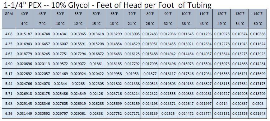
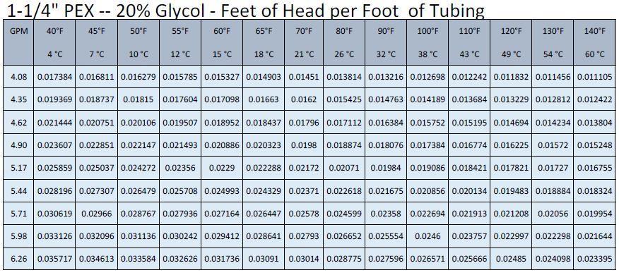
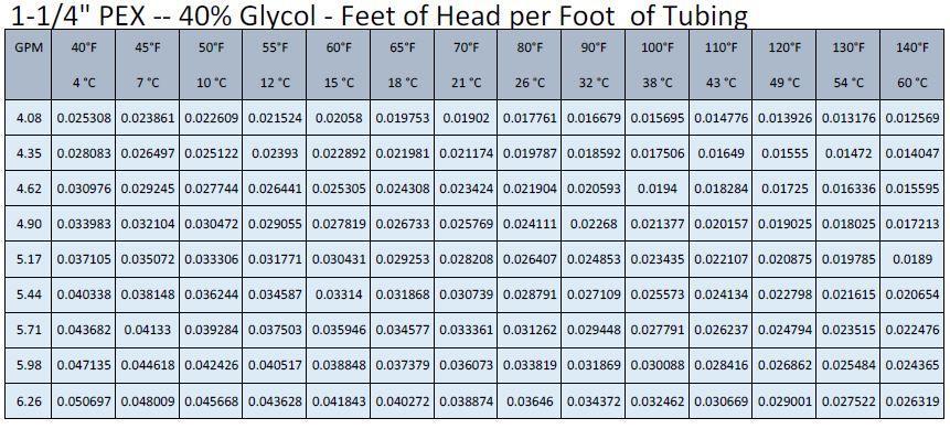
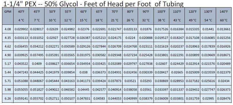
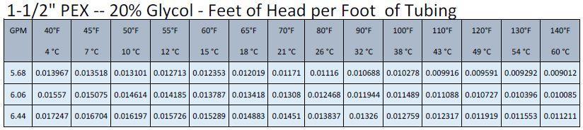
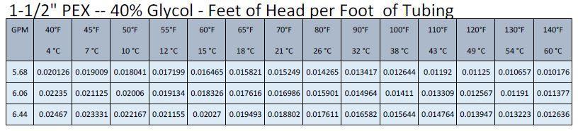
7 Example of head calculation To calculate the head pressure for the correct water flow, the pipe length must be measured and all fittings counted. It is advisable to use flexible red oxygen barrier pex piping to avoid as many elbows as possible. All fittings have an equivalent length of pipe already calculated, see the chart on page 8, and example above. Add up the equivalent length of pipe for the fittings, =25.5. then add the actual pipe, = of 1 pipe. Once you know the total length of pipe, use the (1 PEX 10% Glycol- Feet of head per 100 feet of tubing chart), page 16 to get the head for 100 of pipe, at 40 F and 4.91 GPM, is ( ) feet of head per foot x =3.26 ft. of head. Add up all head calculations, = ft. of head. Next we will look at the Wilo Pump curve on page 31. If using the CX30SE (Free Cooling option) the units pressure drop is 4.5 PSI when active. 7


8 Notes: The example loop above has a volume of 4.5 gallons. The internal thermal expansion tank is 2 liters or.52 Gallons. An additional thermal expansion tank may be required. There are many thermal expansion calculators on the internet, the following is an example. Minimum loop pressure is 14.5 psi, maximum pressure is 43.5 psi, and ideal pressure is 29 psi. The Lowest temperature is 44 F, the highest temperature is 131 F, the Initial pressure is 14.5 psi, and the final pressure is 29 psi. An air scoop should be installed above the expansion tank to remove any air in the circulation loop. PEX Fittings Pressure Drops 8

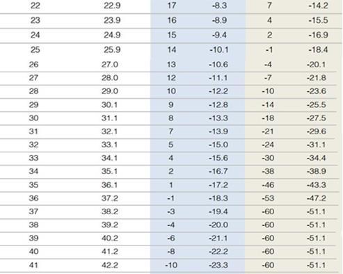
9 Freeze protection 9

10 10

11 11

12 12

13 13

14 14

15 15

16 16

17 17

18 18

19 19

20 20
21 21

22 22
23 23


24 24
25 Friction Loss, Steel, Copper and CPVC Pipe 3/4 inches Volume Flow (gal/min) Volume Flow (gal/hr) Velocity (ft/sec) Friction Head (ft/100 ft) Friction Loss (psi/100 ft) inches Volume Flow (gal/min) Volume Flow (gal/hr) Velocity (ft/sec) Friction Head (ft/100 ft) Friction Loss (psi/100 ft)
26 1 1/4 inches Volume Flow (gal/min) Volume Flow (gal/hr) Velocity (ft/sec) Friction Head (ft/100 ft) Friction Loss (psi/100 ft) /2 inches Volume Flow (gal/min) Volume Flow (gal/hr) Velocity (ft/sec) Friction Head (ft/100 ft) Friction Loss (psi/100 ft)

27 Selecting the proper circulator (Taco used as example) When using a buffer tank a second non-pwm circulator can be used be used. The head calculation must be done using the buffer tank output to the fan coil side of the loop. This will be used to select a circulator using the instructions below. See page 37 for wiring details. Plot the target operating point just established on a graph showing the pump curves of several Taco candidate circulators as shown in Figure 1. Figure 1 Look for a circulator with a pump curve passing though, or relatively close to, the target operating point. For this example we will use feet of head. The Taco 0012 meets this criterion. So does a Taco Because the curve for the 0012 is slightly above the target operating point the flow rate in the system will be slightly higher than the target value. This is not necessarily a problem. It means that a slight safety factor would be present to cover for slightly greater installed piping lengths, or other unforeseen conditions that might increase system head loss. The pump curve for the 0010 circulator passes just under the target operating point. If this circulator were selected the flow rate in the system would be slightly less than the target flow rate. If the drop in flow was limited to no more than five percent the difference in the system s thermal performance would be 27
28 negligible, and thus the smaller circulator might still be a suitable selection. However, it is generally considered poor practice to select a circulator that yields flow rates less than the calculated target flow rate for the system. Another option, the designer could investigate before making the final circulator selection is using larger piping. In addition to selecting a circulator that produces a flow equal to or slightly above the target value, other factors should be considered: Additional Notes 1. To achieve reasonable wire-to-water efficiency, the target operating point should fall within the middle third of the flow rate range covered by the pump curve for the selected circulator. It s not good practice to select a circulator where the target operating point falls near the outer ends of the pump curve, even if the pump curve is still above the target operating point. Doing so would force the circulator to operate at relatively low efficiencies that increase system operating cost. 2. In systems using zone valves (or manifold valve actuators) select a circulator with a relatively flat pump curve. This minimizes changes in differential pressure as the zone valves open and close. 3. In systems having a high flow rate and low head loss requirements consider using two smaller circulators in parallel rather than a single larger circulator. The effective pump curve for two identical circulators in parallel is found by doubling the flow rate at every value of head. In effect the pump curve of a single circulator is stretched out to twice its length along the horizontal axis as shown in Figure 3. Figure 3 28

29 If two or more circulators are used in parallel, be sure to include a check valve downstream of each circulator to prevent reverse flow should one circulator be inoperable. 4. Be very careful when selecting circulators with steep pump curves for use in high temperature systems. The potential for vaporous cavitation within the circulator is higher in such situations. Avoiding cavitation will require high static pressures. This article has outlined the steps that hydronic system designers can follow to select an appropriate circulator for a given piping system. In many cases, two or more circulator options can each yield acceptable performance based on tradeoffs in system piping. A good selection addresses the total owning and operating cost of the system (circulator and piping) over its design life rather than just first cost. Excessive oversizing of circulators increases initial as well as life cycle costs and should be avoided. The wide range of hydronic circulators available from Taco allows conscientious designers to properly match the circulator to the task. 5. When selecting components for a system, it is worth noting the effect that their imparted resistance has on pump performance. It may be on thing to see the final number that is calculated as part of establishing the head loss of the piping system, but how does that number actually affect the flow rate in the system? This becomes very clear when comparing a system where a conventional weighted flow check is installed versus a pump with an integral flow check (00-IFC), as illustrated in Figure 4. Figure 4 Shown is the 008 circulator, but this example holds true for any model. When a common Taco Model 219, ¾ Flo-Chek is installed along with the pump the imparted resistance shifts the pump curve down and to the left as illustrated. The hydraulics of the 00 Circulators with Integral Flow Checks (00-IFC) has been specifically 29
30 engineered to minimize the total impact of the built-in flow check, hence the smaller pump curve shift. Just the difference of using a 008-IFC versus a standard 008 can be seen in the flow output of the circulator at a given head loss. Example 5: If you had a system with 10 feet of head loss, you would expect to get 8 GPM of flow in the system. Say you forgot to add in a flow check to prevent gravity flow. If you were to add a 219, ¾ Flo-Chek, all of a sudden you would have a flow rate of 2 GPM through the same system. If you decided to install a 00-IFC instead of the in-line flow check, the flow would be just over 7 GPM. The selection of components, correct figuring of total system head loss, and matching the target operating point with the appropriate circulator can have a major impact on the performance of a system. 30

31 Internal CX30 WILO Pump Pipe Insulation All loop piping must be insulated per local and national mechanical codes. For For design tips and a thickness calculator please visit 31
32 Heat Pump Installation Installation position Note: Installation must be carried out by professional personnel. 1. The recommended mounting pad should be 1 to 1 ½ above ground level. 2. A drainage path or other facilities should be arranged around the outdoor unit, to avoid flooding the outdoor unit. 3. To install the unit on a balcony or on top of a building, the installation site must meet the allowable bearing capacity of the building structure, without affecting the structural safety. 4. Ensure the unit is well ventilated; the direction of air exhaust should be kept away from the windows of neighboring buildings. Moreover, adequate service clearance should be kept around the unit. 5. The unit should not be installed in places accompanied with oil, inflammable gases; corrosive components e.g. sulfur compound, or high-frequency equipment. 6. The unit must be installed upon a reliable machine base or framework. Weight capacity of framework should be 3 times of the outdoor unit s body weight, and safeguard measures should be taken to avoid a malfunction of the fasteners. 7. The unit must have extra precautions taken when it is installed at sites with hurricane/ earthquake hazards. Consult the appropriate professional to determine the needed requirements 8. Midair or suspended installation should be avoided as much as possible, falling machines may result in personal injury and property damage. 32
33 Clearances (unit: mm) 200mm = 8, 350mm =14, 400=16, 500=20,1000=40 33
34 Electric connections General Note! Electrical installation and service must be carried out under the supervision of a qualified electrician. Electrical installation and wiring must be carried out in accordance with the NEC. The heat pump must not be connected without the permission of the electricity supplier and must be connected under the supervision of a qualified electrician. Wires, spare parts and materials etc. must satisfy the relevant standards issued by the host country or region. The heat pump does not include an AC disconnect or switch on the incoming electrical supply. The power supply cable must be connected to a circuit-breaker with at least a 3 mm breaking gap. Incoming supply must comply with the technical requirements, with ground wire, via a distribution board with breakers. Maximum current draw is 13 amps, minimum wire size is 12 AWG, Minimum breaker size is 20 AMP. 34
35 Electric connections Using Internal PWM Pump If the Wilo RS 25/7.5 PWM pump does not have the required pressure at the targeted flow rate, a second Wilo RS 25/7.5 may be added to increase the total pump pressure. This will double the head pressure at the targeted flow rate. See page 36 for wiring details. Contact us for more information on booster pumps. 35

36 Second PWM Pump Wiring Use proper splicing connectors to connect the second PWM pump in parallel to CN6. 36

37 When using a second NON-PWM water pump When using a second NON-PWM water pump, use terminals C6 and L2 for power. 37
38 Seasonal Switch Valve The G3 port can be used to control a seasonal switch valve. The seasonal switch valve is used to isolate the floor coils (if needed) from the fan coils when switching over from heating to cooling. The seasonal switch valve is controlled by parameter 14. When parameter 14 is 0, the valve is configured as a seasonal Switch. When parameter 14 is 1, the valve is configured as a solar pre-heat valve. See detailed wiring diagram on the next page. 38
39 G3 VALVE Seasonal Switch Valve/ Solar Pre-heat Valve 39

40 G1 Valve DHW and AC 40
41 Master Slave Wiring Heating Mode Only When using the master slave configuration, the heater control port of the master unit is connected to the AC 2 nd switch port of the slave unit. This port is activated when the master unit cannot reach the target temperature within 15 minutes. The slave unit must be turned on and heating mode must be selected. There is no limit to the number of slaves that can be used. 41
42 System filling with Propylene Glycol and water At or near the chiller a flush/fill valve assembly must be installed. This can be made with three ball valves and a couple hose fittings. See example below. Pre-mix the propylene in a container large enough to hold the loop volume. Using a filling pump and 3 hoses, place one hose in the glycol container and connect it to the suction side of the pump, prime the pump, then connect the other hose to the pump discharge and the other end to the valve C that is closest to the fan coils. Using a third hose, connect it to valve B, closest to the chiller. Close the middle valve A. Minimum loop pressure is 14.5 psi, maximum pressure is 43.5 psi, and ideal pressure is 29 psi. 42
43 Close the input valve to each fan coil except the last coil (4). Turn the pump on and run it, when the bubbles stop coming out of the discharge hose turn on the ball valve on coil (1), wait for the bubbles to stop, then do the same for coil number (2), then (3). All CX Chillers are required to have a flow switch installed in the loop. Air in the system may cause a flow switch alarm; the controller will display a P5 or a P6 error code. Proper and even flow through each fan coil is critical for both heating and cooling. This can be done with flow meters or ball valves installed at each fan coil supply pipe. Set each fan coil to the same temperature and fan speed. Using an accurate digital thermometer to adjust each ball valve until the coil return temperatures are even. This can be done in cooling or heating mode. 43
 Two-colored indicator light: when in standby, the blue light is on; when the compressor is on, the red light is on; when there is an error, the red light is on.")
44 CONTROL PANEL The control panel contains a LCD and 6 operational keys (as show below). It retains its memory when powered off and be used as a timer. 1. Key functions (1) Two-colored indicator light: when in standby, the blue light is on; when the compressor is on, the red light is on; when there is an error, the red light is on. For more details, please check the fault code sheet. (2) Key on/off : power on/ power off. (3) Key down : adjust the clock or set the time. 44
45 (4) Key down : it s a combined key to decrease the numerical value. Continuous pressing causes a continuous decrease. Short pressing increases the value by one. (5) Key up : it s a combined key also, but just the opposite to the down key. Continuous pressing causes a continuous increase. Short pressing increases the value by one. (6) Key confirm : confirms previous operations. (7) Key mode : operational mode s switch, it s also a combined key. 2. Icon Meaning No. Icon meaning No. Icon meaning No. Icon meaning 8 Clock display 9 Returned AC Temp. 10 Maintain icon 11 Lock icon 12 Temperature icon (Reserved) 13 Parameter number icon 14 AC Cooling icon 15 N/A 16 AC heating icon 17 N/A 18 Water/ground source display 19 Parameter icon 20 Ambient Temp 21 Timer on icon 22 Timer off icon 23 Clock Icon UNIT OPERATION 1. Turning the unit on and off To start the unit, press and hold the On/Off key for one second. To stop the unit, press and hold the On/Off key for one second. 2. Mode Switch (2 modes total) Under mode standby or on, press the M key repeatedly to cycle through the icons. AC cooling -> heating -> When a mode is selected, press the button to confirm, the icon will be lit solid, the heat pump mode will be as selected. 3. Changing the Cooling/Heating parameter setting procedure A. When in standby mode, the unit will operate in accordance with the factory default temperature or last modified temperature. B. Modification method for standby temperature. In the on / standby mode, press key M and for 3 seconds, the current operating mode light will flash; by pressing the M key, you can switch modes in the following order: Cooling / heating press mode and press key or to set the value, then press then exit and save current changes; to confirm the key to confirm, If you didn t press key to confirm, it will exit the parameter modification automatically 15 seconds later. Previous changes will not be saved. 45

46 Detailed settings as follows: No. Meaning 1 2 Selected temperature range Default temperature AC cooling returned 10 C ~ 25 C 17 C water temp AC heating returned 10 C ~ 55 C 30 C water temp Operation for modifying settings UNIT OPERATION Time adjustment Press the key, time hour value will flash, then press or, the value will increase or decrease. Press and hold either key and the value will cause a continuous increase or decrease. Press the to confirm settings and exit the time mode. 5. Time setting You can set one time to start and one time to turn off. You can select cycling the on /off settings or just turn on and follow the set point. A. Setting the time on method: 1. Press for 3 seconds to set the time, you will see flash as show below. 46


47 2. Press the or key to modify the time, then, press the key to confirm. This setting is only valid for one time. If you want to cycle the time please press the after setting the time, then press the key to confirm. B. Timing off method is the same method as timing on. C. Press the for 3 seconds to enter timing mode, press to cancel the time setting. Parameter Checking and Setting Please press the M+ key for 3 seconds and enter parameter setting mode as show below. In this example 01 is the parameter code, and 78 is the parameter value. Use the key to move from NO. to VALUE. After changing parameters, press the to save the changes. Parameter codes and values are listed below. 47
48 Parameter codes and values No. Name Range/meaning Default Status 00 Power down auto restart 0: no restart : 1: restart 1 check/set 01 DHW water temp. return differential 2~15,minus differential 2 check/set 02 Air conditioning return differential 2~15,minus differential 2 check/set 03 Copper pipe temp to start defrost -20~5 0 C check/set 06 Defrost stop temp 10~35 30 check/set 07 Max defrost duration time 15~99 mins 15 check/set 08 Defrost interval time between 2 defrosts 15~99 mins 35 check/set 09 Air temp to start DHW electrical heater -20~20 0 check/set 10 Air temp. to start AC electrical heater -20~20 0 C check/set 11 Reserved check/set 12 Compressor discharge air protection temp A0 ~ C7 = (212 F~260 F) B0 check/set 13 Defrost interval time multiply rate 0: no defrost 1~4: parameter 08*1~4 1 check/set 14 Function parameter 0: G3 is seasonal switch valve: 1: G3 is solar pre-heat valve: 0, 1, 2 0: don t stop 26 AC water pump running mode 1: stops when it reaches target temp 2: run 1 minute every 15 minutes then stops 2 nd heat source control validation 0, 1 (0: 2 nd heat source control 27 disable; 1: control enable) 0 check/set 0 check/set 0 check/set 28 Air temp to start 2nd heat source control -15~10-15 check/set NOTE: 1. Press the key for 5 seconds, you will hear a beep. The factory default parameters will be reset. Usage of Parameter 26: AC water pump working modes. If you are NOT using an AC buffer tank, the Parameter 26 is set to 0. The AC water pump will work continuously to keep the AC loop water temperature always the same. If you are using an AC buffer tank, the parameter 26 will be set to 1. 48
49 UNIT OPERATION Machine operational status Checking Press both M and for 3 seconds to enter machine status mode, see table below. C0 is part or parameter number, 28 stands for parameter. Parameter 0 means system on, 1 means system off. For more detail, please check the table below. Parameter Checking Only Press M + for 3 seconds to search and check parameters. No. Name Range/meaning Status 00 Outdoor pipe temp. -30~97 check 01 inverter: -30~97 (0: disconnected; Compressor exhaust has temp. 1: connected) check 02 Ambient temp. -30~97 check 03 AC inlet water temp. -30~97 check 04 DHW pipe temp. -30~97 check 05 Solar pipe water temp. -30~97 check 06 Switch input status 0 (heating & cooling) 1 (heating only) check 07 Switch input status 0 (air source); 1 (water source) check 08 Reserved 09 Switch input status 0 (G1 valid); 1 (G1 invalid) check 10 High pressure switch status 0: (off); 1 (on) check 49
50 11 Overcurrent protect switch status 0: (off); 1 (on) check 12 Low pressure switch status 0: (off); 1 (on) check 13 Inside water flow switch 0: (off); 1 (on) check 14 Outside water flow switch 0: (off); 1 (on) check 15 The 2nd high pressure switch status 0: (off); 1 (on) check 16 Defrost temp. check 17 Air conditioning antifreeze temp. check 18 System antifreeze Temp. check 19 Compress Inverter: actual running rate check 20 Outdoor fan motor 1: run; 0:stop check 21 Crankcase heater 1: run; 0:stop check 22 4-way valve 1: run; 0:stop check 23 Bypass valve 1: run; 0:stop check 24 Solenoid valve 1 1: run; 0:stop check 25 Solenoid valve 2 1: run; 0:stop check 26 Solenoid valve 3 1: run; 0:stop check 27 Electrical heater 1 1: run; 0:stop check 28 Electrical heater 2 1: run; 0:stop check 29 C4 water pump 1: run; 0:stop check 30 C5 water pump 1: run; 0:stop check 31 C6 water pump 1: run; 0:stop check 32 Functional parameter 0-99 (accumulated days from last sterilization till now) check 33 Cooling target temp. check 34 Heating target temp. check 35 Reserved 36 Reserved 37 Outdoor unit module temp. -30~97 check 38 Outdoor unit returned gas temp. -30~97 check 39 Internal pipe temp. -30~97 check 50


51 Displays for the different modes (1) Air source heat pumps icons. (3) Powered off display If it has a timer on/off setting, there is a timer icon to indicate it. 51

 The communication")
52 (4) AC cooling display (5) heating display If it has a timer on / off setting, there is a timer icon to indicate it. Controller Communications (2wire) The communication cable can be extended to 300 using 16 AWG wire. 52

53 Function Selection Switch: SW1 This switch is on the Water System PCB. Unit must be power cycled if switch settings are changed. Switch Description Default SW1-8 OFF: cooling valid OFF SW1-7 OFF: heating valid OFF SW1-6 OFF: DHW valid; ON: DHW invalid ON SW1-5 OFF: G1 valid; ON: G1 invalid ON SW1-4 OFF: inverter outdoor model OFF SW1-3 Reserved ON SW1-2 Reserved ON SW1-1 ON: air source ON 53
54 ERROR CODES When the machine has an error, the control will show P or E at the AC temp location and show the error code at the DHW temp location, press key to search more error codes that may have happened at the same time. Please see table below for error code meaning. Error code list Error Code E1 E2 E3 E4 E5 Error Meaning Compressor discharge gas high temp. protection Outdoor air temp sensor fault Pipe temp or returned air temp sensor fault AC returned water temp. sensor fault AC output water temp. sensor fault Outdoor Led2 Flash s 10 times Flash s 3 times Flash s 6 times No flash No flash Possible Error Reason 1. Refrigerant low 2. throttling device problem 3. Water flow volume is too low Sensor open circuit or short circuit Sensor open circuit or short circuit Sensor open circuit or short circuit stop compressor in AC Sensor open circuit or short circuit stop compressor in AC Error Solution 1. Check the refrigerant pressure and check if there is leakage. 2. Check the thermostatic expansion valve. 3. Check the water flow volume and if the water pump is too small or is blocked. 1. Reconnect the sensor 2. Measure the sensor resistance at different temperatures, if it is out of range change the sensor. 1. Reconnect the sensor 2. Measure the sensor resistance at different temperatures, if it is out of range change the sensor. 1. Reconnect the sensor 2. Measure the sensor resistance at different temperatures, if it is out of range change the sensor. 1. Reconnect the sensor Measure the sensor resistance at different temperatures, if it is out of range change the sensor. 54
55 E6 Hot water temp. sensor fault No flash Sensor open circuit or short circuit stop compressor at DHW. Reconnect the sensor Measure the sensor resistance at different temperatures, if it is out of range change the sensor. E7 Solar water temp. sensor fault No flash Sensor open circuit or is shorted. 1. Reconnect the sensor 2. Measure the sensor resistance at different temperatures, if it is out of range change the sensor. FB/ E8 Outdoor coil high temp protection Flash s 15 times Outdoor unit heat exchange not good 1. Check if the outdoor is too near the wall. 2. Check if the fan is blowing. 3. Check if the coil temp sensor has an error. E9 AC antifreeze twice No flash Inlet or Outlet water temp is lower than 39.2 F, AC antifreeze 2 times within 90 minutes. Check inlet and outlet water temp sensors, they may be loose. EA DHW antifreeze twice No flash DHW tank water temp is lower than 41 F, antifreeze 2 times within 60 minutes. Check DHW tank temp sensor is mounted at a warm location on DHW tank top Eb Indoor refrigerant pipe temp sensor error No flash F1 Voltage protection Flash s 1 time Voltage too high or too low, (after voltage becomes normal, 165~265VAC, unit will auto restart). 1. Reconnect the sensor 2. Measure the sensor resistance at different temperatures, if it is out of range change the sensor. Check if the electricity supply is ok, wires are not loose. 55
56 F2 F3 Rating module PFC error Compressor stopped abnormally Flash Flash IPM module (PFC) connection wire loose or IPM module defective. Power supply error, electromagnetic interference, Outdoor PCB error or bad compressor. 1. Check if there is any burn marks on IPM PCB. 1. Shut off the power supply wait for 3 minutes then reconnect the power. 2. Check that all wire connections are not loose. F4 Outdoor IPM module radiator sensor fault Flash s 5 times IPM module temp sensor error. Reconnect or change the sensor. F5 Outdoor unit current sensor fault Flash s 8 times Running Current sensor fault or loose wires. Reconnect or change the sensor. F6 F7 F8 IPM or module control board fault Compressor fail to start Outdoor unit overcurrent Flash s 14 times 1. Communication wire between IPM module and outdoor PCB. 2. IPM Module is burned or IPM has no power from the AC contactor. 3. Outdoor PCB Communication port error. 4. Check if the IPM module (PFC) connection wire with outdoor PCB is not loose. 5. Check if there is any burn marks on IPM. 6. Check the AC connection at the IPM. 7. Check if the outdoor PCB has an error. Flash Decided by Outdoor unit Check the wire connections, PCB and compressor. Flash s 11 times Compressor working current too high 1. Check the compressor wire connections. 2. Disconnect the power supply and reconnect it after 3 minutes. 3. Check if the refrigerant volume is correct 4. Open the heat expansion valve 360~180 56
57 F9 FA Exhausted gas temp. sensor fault Outdoor module overheat, over-current Flash s 7 times Flash s 5 times IPM temperature too high, compressor current too high. 1. Reconnect the sensor. 2. Measure the sensor resistance at different temperatures, if it is out of range, change the sensor. 1. Disconnect the power supply and reconnect it after 3 minutes. 2. Check if the IPM connection wires are not loose or IPM is burned. P1 high pressure protection Flash s 2 times 1. High pressure switch loose or faulty. 2. There is air inside the water circuit. 3. Water flow volume is too low, water pump is too small or faulty. 4. Throttling device (expansion valve) problem. 5. There is air inside the refrigerant system or refrigerant volume is too high. 1. If the error displays before the compressor starts, it means high pressure switch error. Please reconnect high pressure switch or change the switch. If the error displays when water temp is about 104 F, please check if the high pressure switch or mid pressure switch is misconnected by mistake. Refer to the wiring diagram. 2. Clean and purge the air from the water circuit. 3. Clean the Water circuit filter or add a bigger water pump if water flow is not enough. 4. Open the thermostatic expansion valve 360~180, 5. Measure the refrigerant pressure, revacuum the system and recharge the refrigerant. 57
58 P2 Low pressure protection Flash s 9 times 1. Low pressure switch loose or faulty. 2. Throttling device (expansion valve) problem 3. Heat expansion valve needs to be preheated. 4. Refrigerant low (leaks) 1. If the error displays before the compressor starts, it means low pressure switch error. Please reconnect the low pressure switch or change it. 2. Open the thermostatic expansion valve 360~ Disconnect the power for 3 minutes, connect power again and turn on the unit. Repeat this 2 or 3 times to preheat the expansion valve. 4. Check for refrigerant leakage. P5 indoor unit water flow fault No flash 1. Low water flow. 2. Water flow switch fault. 1. Clean the water filter, check water pump flow. 2. Check and reconnect water flow switch. P6 outdoor unit (water source side) water flow fault Flash s 17 times 1. Water source side water flow too small. 2. Water flow switch fault. 1. Clean the water filter, check water pump flow. Test the water flow switch. P7 phase loss Flash Power connection fault Reconnect power supply wires P8 Flash Power connection fault Reconnect power supply wires P9 Flash Power supply connection fault or communication between indoor and outdoor PCB fault 1. Check the power supply wire connection and wires between outdoor PCB and indoor PCB. 2. Check if the outdoor PCB has an error. 58
59 Test run Preparation After finishing the installation tasks, please check the items below: 1. Check the dip switch settings on the water control PCB, refer to page Check if the power cable is connected correctly, and check if the screws are secure. 3. Check if the communication wire is connected correctly. 4. Water circuit Verify that the water pipes are connected correctly, and the pipe dimensions are correct. Verify that all the shut off valves and manual valves are open. Insulate all water supply and return pipes. Water or Glycol Filling (See page 42) 1. With a hose and filling pump connected to the CX45 water system, and all air exhaust valves open in the water system, fill the water loop with water and glycol mixture. Keep the air exhaust valves open until there is a continuous flow of water and glycol mixture coming out of the air exhaust valve. Then close the air exhaust valves. See page 42 for more details. 2. Discharge the air for both domestic hot water system and air conditioning water system, including all usage terminals such as domestic hot water tank, fan coils, radiators and etc. Note! To avoid freezing the heat pump when the air temperature drops below 32F in winter, you must use an appropriate glycol and water mixture just in case the electricity is cut off. We recommend biodegradable non-toxic SPP Corn Glycol, any Propylene Glycol (PG) can be used. Alternatively, Ethylene Glycol (EG) can be used however this is a poisonous and toxic product that we do not recommend. Running a Test Turn on the heat pump and select heating mode. Verify that the unit is running properly, the compressor will start in 3~5 minute after powered on. The internal pump should start running at 100% and slowly ramp down. There is a 3 digit display on the PWM PCB that shows the pump speed. There are also 3 switches, sw1, sw2, and sw3. Pressing sw2 once displays a 0, twice displays return water temp, pressing it a third time displays leaving water temp. MOST IMPORTANT! 1. Always maintain an electrical connection with heat pump to enable the antifreeze function. 2. Calculate the loop resistance in feet of head, and make sure, if needed, to select a big enough water pump for the air conditioning water circuit at the required flow rate. 3. The initial test should be done in heating mode. Make sure it is not in cooling mode during first operation or running a test until you make sure the air conditioning circulation pump is working properly and water is flowing smoothly. 59
INSTALLATION & OPERATION MANUAL
 DC INVERTER AIR TO WATER HEAT PUMP AC series Heating & Cooling series CX30 INSTALLATION & OPERATION MANUAL Version 1.5 1 Table of Contents Safety Precautions... 3 Components... 4 Hydronic piping and design
DC INVERTER AIR TO WATER HEAT PUMP AC series Heating & Cooling series CX30
 DC INVERTER AIR TO WATER HEAT PUMP AC series Heating & Cooling series CX30 Installation and Operation Manual Version 1.7 1 Table of Contents Safety Precautions... 3 Components... 4 Hydronic piping and
Selecting Circulators TD10 EFFECTIVE: SUPERSEDES:
 TACO COMFORT SOLUTIONS : HOME HEATING BASICS Selecting Circulators TD EFFECTIVE:.3. SUPERSEDES:.. This article shows you how to select a Taco circulator that lets the hydronic system you re designing perform
DC INVERTER AIR TO WATER HEAT PUMP
 DC INVERTER AIR TO WATER HEAT PUMP Installation and Operation Manual CX34 Options for Heating, Cooling and Domestic Hot Water Version 1.4 1 Table of Contents Safety Precautions... 3 CX34 components...
AIR TO WATER HEAT PUMP
 DC INVERTER AIR TO WATER HEAT PUMP For Use with units shipped before 10-12-2018 (If unsure, contact Chiltrix technical support dept. with the serial number) Installation and Operation Manual CX34 Options
Chiltrix 5.1 Thin DC - Inverter Water Fan Coil Unit Floor, Wall or Ceiling Universal Mount Manual
 Chiltrix 5.1 Thin DC - Inverter Water Fan Coil Unit Floor, Wall or Ceiling Universal Mount Manual Version 1.5 1 CONTENTS CHAPTER 1 GENERAL INTRODUCTION...3 1. Preface... 3 2. Product Introduction... 3
Warning: 230V / 1ph / 50Hz V / 3ph / 50Hz. Remarks: Make sure that you have enough power. (See page 15 Cable table)
") 1 2 Warning: - Do not place your hand or any other objects into the air outlet and fan. It could damage the heat pump and cause injuries; - In case of any abnormality with the heat pump, cut off the power
1 2 Warning: - Do not place your hand or any other objects into the air outlet and fan. It could damage the heat pump and cause injuries; - In case of any abnormality with the heat pump, cut off the power
Aqua Balance. AquaBalance TM CONTROL MODULE QUICK START GUIDE LEGEND
 Aqua Balance AquaBalance TM CONTROL MODULE QUICK START GUIDE 10 1 Domestic Hot Water temperature setpoint decreasing button 2 Domestic Hot Water temperature setpoint increasing button 3 Central Heating
USER S INFORMATION MANUAL
 USER S INFORMATION MANUAL HOT WATER HEATING BOILERS DOMESTIC WATER HEATERS 150,000-300,000 Btu/hr MODELS EB-EWU-02 IMPORTANT INSTALLER - AFFIX INSTALLATION MANUAL ADJACENT TO THE BOILER CONSUMER - RETAIN
INSTALLATION MANUAL GEO-BOOST GROUND LOOP HEAT EXCHANGER
 1103 N HIGH CROSS RD URBANA, IL 61802 1-773-492-1893 INSTALLATION MANUAL GEO-BOOST GROUND LOOP HEAT EXCHANGER REV 1.0 The Geo-Boost system consists of the Geo-Boost heat exchanger and a relay controller
INSTALLATION MANUAL GEO-BOOST GROUND LOOP HEAT EXCHANGER
 INSTALLATION MANUAL GEO-BOOST GROUND LOOP HEAT EXCHANGER Build Equinox support@buildequinox.com (773)-492-1893 Rev 2.0-05/10/2018 Build Equinox 2018 The Geo-Boost system consists of the Geo-Boost heat
CAUTION. Installation Manual
 System Controller SC-301-6M CAUTION Installation Manual In order to use this product safely, read this installation manual carefully and follow the installation instructions. Potential dangers from accidents
Wired Controller XK60
 Owner's Manual Commercial Air Conditioners Thank you for choosing Commercial Air Conditioners, please read this owner s manual carefully before operation and retain it for future reference. User Notice
OWNER S MANUAL. Vintage Classic HEAT COOL models. Proudly Made in the USA
 OWNER S MANUAL Vintage Classic HEAT COOL models Proudly Made in the USA support@aquacomfort.com www.aquacomfort.com/service-and-support 888-475-7443 Manufacturing High Quality, High Efficiency Heat Pump
Part 5. Troubleshooting. 1. Normal Air Conditioner Phenomenon Air Conditioner Protection in Common
 Part 5 1. Normal Air Conditioner Phenomenon... 1611 2. Air Conditioner Protection in Common... 1611 3. Malfunction Code and... 162 160 1. Normal Air Conditioner Phenomenon 1.1 When outdoor unit appears
Bulletin (Jan 2011) And User s Guide
 And User s Guide") Bulletin 30 32 (Jan 2011) Unichiller Installation And User s Guide Customer Service If you have questions about Installation, operation and Maintenance of the Unichiller or would like to order replacement
Bulletin 30 32 (Jan 2011) Unichiller Installation And User s Guide Customer Service If you have questions about Installation, operation and Maintenance of the Unichiller or would like to order replacement
INSTALLATION AND USER MANUAL
 INSTALLATION AND USER MANUAL Thank you for choosing our product and trusting our company. This manual is to provide you with necessary information for optimal use and maintenance, please read carefully
PACKAGED AIR COOLED Product Data Catalog
 PACKAGED AIR COOLED Product Data Catalog MODELS ASP-10A ASP-15A ASP-20A ASP-00P ASP-00F ASP-00G A MEMBER OF MARDUK HOLDING COMPANY, LLC The Leader in Modular Chillers ETL and CSA Approved CHILLER MODULES
15,000 BTU Portable Air Conditioner
 Instruction Manual 15,000 BTU Portable Air Conditioner Model: HYAC15 READ AND SAVE THESE INSTRUCTIONS Please read and follow the instructions in this user manual even if you feel you are familiar with
INSTALLATION AND USER MANUAL
 INSTALLATION AND USER MANUAL t Thank you for choosing Aqua inverter heat pump. This manual provides you necessary information for optimal use and maintenance, please read it carefully and keep it for subsequent
Model No.: PS08-01 PS10-01 Ref: KY80 KY100
 8,000/10,000/12,000 BTU Portable Air Conditioner Operating Instructions Model No.: PS08-01 PS10-01 Ref: KY80 KY100 Model No.: PS12-03 Ref: KY120 3119233 V160310 Thank you for choosing a Soleus Air Portable
DC INVERTER MONOBLOCK AIR TO WATER HEAT PUMP AND CHILLER. User Manual
 DC INVERTER MONOBLOCK AIR TO WATER HEAT PUMP AND CHILLER User Manual REV:WR-2016V2-1- Contents list 1. General ------------------------------------------------------------------------- 3 2. System description
OPERATION MANUAL. Daikin Altherma indoor unit EKHVMRD50ABV1 EKHVMRD80ABV1 EKHVMYD50ABV1 EKHVMYD80ABV1
 OPERATION MANUAL EKHVMRD50ABV1 EKHVMRD80ABV1 EKHVMYD50ABV1 EKHVMYD80ABV1 EKHVMRD50+80ABV1 EKHVMYD50+80ABV1 CONTENTS Page 1. Definitions... 1 2. Introduction... 2 2.1. General information... 2 2.2. Scope
FREQUENTLY ASKED QUESTIONS
 HEAT PUMP INVERTER R-410A All-in-one, all year round heating, cooling and domestic hot water supply solution FREQUENTLY ASKED QUESTIONS WANT TO KNOW MORE? AVERAGE ANNUAL CO 2 EMISSIONS Daikin Altherma
AHWG Remote Mount Hot Water Generator Module
 A Remote Mount Hot Water Generator Module For GT-PE (50YPS) Series Outdoor Split Unit Installation, Operation & Maintenance Instructions 97B0080N02 B Model Nomenclature Example 3 Description and Installation
OWNER S MANUAL HIGH WALL INVERTER. (English) (BSHVD1S SERIES)
 (BSHVD1S SERIES)") OWNER S MANUAL HIGH WALL INVERTER (English) (BSHVD1S SERIES) IMPORTANT As with any product that has moving parts or is subject to wear and tear, it is VERY IMPORTANT that you maintain your air conditioner
OWNER S MANUAL HIGH WALL INVERTER (English) (BSHVD1S SERIES) IMPORTANT As with any product that has moving parts or is subject to wear and tear, it is VERY IMPORTANT that you maintain your air conditioner
Heat Transfer Products, Inc. 120 Braley Road East Freetown, MA The first totally integrated multiple boiler management control.
 Heat Transfer Products, Inc. 120 Braley Road East Freetown, MA 02717 The first totally integrated multiple boiler management control. USING THIS MANUAL USING THIS MANUAL A. INSTALLATION SEQUENCE Follow
Owner s Manual Super-Slim Four-Way Cassette
 CASSETTE- TYPE AIR CONDITIONER Owner s Manual Super-Slim Four-Way Cassette IMPORTANT NOTE: Read this manual carefully before installing or operating your new air conditioning unit. Make sure to save this
AHWG Remote Mount Hot Water Generator Module for TTP Series Outdoor Split Unit
 A Remote Mount Hot Water Generator Module for TTP Series Outdoor Split Unit Installation, Operation & Maintenance Instructions 97B0080N01 B Table of Contents Model Nomenclature Example 3 Description and
DEHUMIDIFIER INSTRUCTION MANUAL
 MODEL: OBZ-50DHPN CONTENTS SAFETY PRECAUTIONS Warning...2 Caution...2 Electrical information...3 DEHUMIDIFIER CONTROLS Control panel...4 Other features......5 DESCRIPTION OF PARTS Identifying the parts.......6
VMI-1102-A SERVICE MANUAL AIRCONDITIONER DC INVERTER MULTI TYPE MSV1I-09HRDN1-M TAS-09MVHN TAS-12MVHN INDOOR VERTU DC INVERTER MULTI SERIES
 VMI-1102-A SERVICE MANUAL AIRCONDITIONER DC INVERTER MULTI TYPE MSV1I-09HRDN1-M TAS-09MVHN TAS-12MVHN INDOOR VERTU DC INVERTER MULTI SERIES CONTENTS 1. Precaution... 1 1.1 Safety Precaution...1 1.2 Warning...1
Trouble Shooting Guide PWA, 3-phase (D10571)
") Trouble Shooting Guide PWA, 3-phase (D10571) Trouble Shooting Guide Problem Possible Cause Possible Remedy Unit does not start Unit does not cool No power to unit, breaker tripped Low voltage Loose wire
Trouble Shooting Guide PWA, 3-phase (D10571) Trouble Shooting Guide Problem Possible Cause Possible Remedy Unit does not start Unit does not cool No power to unit, breaker tripped Low voltage Loose wire
Part 3 Troubleshooting
 Part Troubleshooting What is in this part? This part contains the following chapters: Chapter See page Troubleshooting 2 Error Codes: Hydro-box 7 Error Codes: Outdoor Units Error Codes: System Malfunctions
Inverter Swimming Pool Heat Pump
 P Inverter Swimming Pool Heat Pump Content I. Application... 2 II. Features... 2 III. Technical Parameter... 3 IV. Dimension... 4 V. Installation instruction... 5 VI. Operation instruction... 9 VII. Testing...
Operating Functions Temperature Parameters
 Operating Functions Temperature Parameters Room set temperature (T set) Room ambient temperature (T amb) Fundamental Functions After powered on, no matter when the compressor is started, the time interval
95M-200. Gas-Fired Direct Vent Modulating Hot Water Boiler. Control Manual And Troubleshooting Guide. P/N , Rev.
 95M-200 Gas-Fired Direct Vent Modulating Hot Water Boiler Control Manual And Troubleshooting Guide P/N 24000604, Rev. C [04/09] WARNING! Revise boiler control parameters only if you fully understand the
ignored. Denotes content that may result in bodily injury and physical damage when ignored.
 SC-201-12M, SC-201-24M Installation Manual Potential dangers from accidents during installation and use are divided into the following two categories. Closely observe these warnings, they are critical
Ductless Split Air Conditioner
 Ductless Split Air Conditioner Service Manual Indoor AW09ESVHA AWESVHA AW8ESVHA AWESVHA Outdoor U09ESVHA UESVHA U8ESVHA UESVHA Design may vary by model number. Please read this manual before using the
User instructions DHP-AT
 User instructions DHP-AT VUGFC202 If these instructions are not followed during installation and service, Danfoss A/S liability according to the applicable warranty is not binding. Danfoss A/S retains
SEMTIC HEATING
 SEMTIC HEATING www.ttshop.se Luxury Air Source Heat Pump - Touch Screen Operation Manual - AXAO-06 AXAO-08 AXAO-11 AXAO-14 AXAO-14/3 AXAO-16/3 AXAO-21/3 0 Operation instruction 1. Main page 1.1. It shows
Installation & Operation Manual Models: TSU
 TSU-I-O Rev A Installation & Operation Manual Models: TSU 150-940 CAUTION: This appliance is not intended for potable water. This manual must only be used by a qualified heating installer / service technician.
DLCLRA. INSTALLATION INSTRUCTIONS Outdoor Unit Single Zone Ductless System Sizes 36 to 58 TABLE OF CONTENTS
 DLCLRA INSTALLATION INSTRUCTIONS Outdoor Unit Single Zone Ductless System Sizes 36 to 58 Fig. 1 - Size 36 TABLE OF CONTENTS PAGE SAFETY CONSIDERATIONS... 2 PARTS LIST... 3 SYSTEM REQUIREMENTS... 4 WIRING...
40KMC KMQ
 40KMC------301 40KMQ------301 OWNER S MANUAL Split system Global cassette indoor unit IR Remote Control Room Controller Zone Manager The unit can be used with infrared Remote Control, with the Carrier
HP50HA ABG Heat Pump
 HP50HA ABG Heat Pump Troubleshooting Guide Residential TSG-ABGHPa Copyright 2017 Hayward Industries Inc. Safety Precautions Warning! High Voltage Electrocution Hazard Hazardous voltage can shock, burn,
5) Do not start or stop the unit by inserting or pulling out the power plug.
 Do not start or stop the unit by inserting or pulling out the power plug.") 3058080 V170306 PURCHASE INFORMATION Thank you for choosing a Soleus Air Portable Air Conditioner. This Owner s Manual will provide you with valuable information necessary for the proper care and maintenance
3058080 V170306 PURCHASE INFORMATION Thank you for choosing a Soleus Air Portable Air Conditioner. This Owner s Manual will provide you with valuable information necessary for the proper care and maintenance
INSTALLATION AND USER MANUAL
 INSTALLATION AND USER MANUAL Thank you for choosing inverter heat pump. This manual provides you necessary information for optimal use and maintenance, please read it carefully and keep it for subsequent
DOLE REFRIGERATING COMPANY 1420 Higgs Road Lewisburg, Tennessee Phone (931)
") DOLE REFRIGERATING COMPANY 1420 Higgs Road Lewisburg, Tennessee 37091 Phone (931) 359-6211 1-800-251-8990 www.doleref.com PHO WATER DEFROST OPERATION & MAINTENANCE MANUAL June 2002 PHO WATER DEFROST Table
DOLE REFRIGERATING COMPANY 1420 Higgs Road Lewisburg, Tennessee 37091 Phone (931) 359-6211 1-800-251-8990 www.doleref.com PHO WATER DEFROST OPERATION & MAINTENANCE MANUAL June 2002 PHO WATER DEFROST Table
OPERATING INSTRUCTIONS
 COMFORT CONTROL CENTER 2 THERMOSTAT OPERATING INSTRUCTIONS PROGRAMMABLE THERMOSTAT MODEL 3314080.000 BLACK 3314080.015 WHITE USA SERVICE OFFICE Dometic Corporation 1120 North Main Street Elkhart, IN 46514
OWNER S MANUAL HIGH WALL INVERTER. (English) (MSHVD1S SERIES)
 (MSHVD1S SERIES)") OWNER S MANUAL HIGH WALL INVERTER (English) (MSHVD1S SERIES) IMPORTANT As with any product that has moving parts or is subject to wear and tear, it is VERY IMPORTANT that you maintain your air conditioner
OWNER S MANUAL HIGH WALL INVERTER (English) (MSHVD1S SERIES) IMPORTANT As with any product that has moving parts or is subject to wear and tear, it is VERY IMPORTANT that you maintain your air conditioner
Q - Series Boiler. Troubleshooting Manual
 Q - Series Boiler Troubleshooting Manual WARNING There are a number of live tests that are required when fault finding this product. Extreme care should be used at all times to avoid contact with energized
OWNER S MANUAL. R 410A Ductless Split System Air Conditioner and Heat Pump
 R 410A Ductless Split System Air Conditioner and Heat Pump Models DLC4(A/H) Outdoor Unit, DLF4(A/H) Indoor Unit Sizes 9K, 12K, 18K, 24K, 30K and 36K Please read the operating instructions and safety precautions
Owner s Manual. Middle Static Pressure Duct Type MEU-18MPH2 MEU-24MPH2 MEU-36MPL2 MEU-48MPL2 MIDDLE STATIC PRESSURE DUCT TYPE AIR CONDITIONER
 MIDDLE STATIC PRESSURE DUCT TYPE AIR CONDITIONER Owner s Manual Middle Static Pressure Duct Type MEU-18MPH2 MEU-24MPH2 MEU-36MPL2 MEU-48MPL2 IMPORTANT NOTE: Read this manual carefully before installing
Residential Gas Condensing Boiler Greenstar ZBR16/21/28/35/42-3A... ZWB28/35/42-3A...
 70 80 99-00-O Residential Gas Condensing Boiler ZBR//8/35/4-3A... ZWB8/35/4-3A... 70 80 993 (03/03) CA/US Operating Instructions Contents Contents Key to symbols and safety instructions............................
Ductless Split Air Conditioner
 Ductless Split Air Conditioner Service Manual Indoor HSU09VHG(DB)-W HSUVHG(DB)-W HSU8VHH(DB)-W HSUVHG(DB)-W Outdoor HSU09VHG(DB)-G HSUVHG(DB)-G HSU8VHH(DB)-G HSUVHG(DB)-G Design may vary by model number.
ASSEMBLY INSTRUCTIONS FOR THE PUMP AND CONTROL UNIT ZPS 18a-01
 ASSEMBLY INSTRUCTIONS FOR THE PUMP AND CONTROL UNIT ZPS 18a-01 1. Use and construction of the pump and control unit The pump and control unit is designed to work with solar collectors in systems with required
SPLIT TYPE ROOM AIR CONDITIONER. WALL MOUNTEDtype INVERTER. Models Indoor unit Outdoor unit AOU 9RLFW1 AOU12RLFW1 ASU 9RLF1 ASU12RLF1 R410A
 SERVICE INSTRUCTION SPLIT TYPE ROOM AIR CONDITIONER WALL MOUNTEDtype INVERTER Models Indoor unit Outdoor unit ASU 9RLF ASURLF AOU 9RLFW AOURLFW R40A CONTENTS. DESCRIPTION OF EACH CONTROL OPERATION. COOLING
Multiaqua Chiller Manual
 Rev. 1.1 Multiaqua Chiller Manual The Multiaqua Chiller System is the only air conditioning/refrigeration system of its kind in the world today offering the degree of application flexibility described
Samsung EHS Heat Pump Test
 Samsung EHS Heat Pump Test The following questionnaire is designed for installers who have experience with heat pumps, are currently MCS accredited, and who want to fast track their Samsung accreditation
Table of Contents. Page 2 of 28
 Rev. 1.1 Table of Contents Page Introduction 3 System Description 4 Electrical & Physical Data 5-6 Description of Electrical Controls 7-8 Chiller Controls Sequence of Operation 9 System Faults 10 Refrigeration
TMC Temperature Monitoring Control Temperature Range -30 to 250 F (-35 to 120 C)
") INSTALLATION/OPERATING INSTRUCTIONS TMC Temperature Monitoring Control Temperature Range -30 to 250 F (-35 to 120 C) The TMC displays and monitors a system's temperature and provides an alarm light and
INSTALLATION/OPERATING INSTRUCTIONS TMC Temperature Monitoring Control Temperature Range -30 to 250 F (-35 to 120 C) The TMC displays and monitors a system's temperature and provides an alarm light and
OPERATION INSTRUCTIONS DEMAND DEFROST CONTROL BOARD MODEL FOR USE WITH MODELS: AFFINITY, ECHELON, ACCLIMATE HEAT PUMP SERIES
 OPERATION INSTRUCTIONS DEMAND DEFROST CONTROL BOARD MODEL 500644 FOR USE WITH MODELS: AFFINITY, ECHELON, ACCLIMATE HEAT PUMP SERIES A047-001 FIGURE 1: Demand Defrost Control Module ANTI-SHORT CYCLE DELAY
SLP98UH SERIES VARIABLE CAPACITY GAS FURNACE WARNING WARNING
 2015 Lennox Industries Inc. Dallas, Texas, USA 506443-01 01/2015 Supersedes 08/2012 SLP98UH SERIES VARIABLE CAPACITY GAS FURNACE Improper installation, adjustment, alteration, service or maintenance can
TAC-09CHSA/*** TAC-12CHSA/*** TAC-18CHSA/*** TAC-24CHSA/*** SERVICE MANUAL WALL MOUNTED SPLIT-TYPEAIR CONDITIONERS. No.TE1307.
 WALL SPLIT-TYP WALL MOUNTED SPLIT-TYPEAIR CONDITIONERS MOUNTED SERVICE MANUAL No.TE1307 Models: TAC-09CHSA/*** TAC-12CHSA/*** TAC-18CHSA/*** TAC-24CHSA/*** CONTENTS: 1. IMPORTANT NOTICE 2. OPERATION DETAILS
AIR COOLED MINI CHILLER
 INSTALLATION MANUAL AIR COOLED MINI CHILLER Большая библиотека технической документации http://splitoff.ru/tehn-doc.html каталоги, инструкции, сервисные мануалы, схемы. INSTALLATION MANUAL This manual
R410A. WALL MOUNTEDtype INVERTER SPLIT TYPE ROOM AIR CONDITIONER. Models Indoor unit Outdoor unit AOYG07LEC AOYG09LEC AOYG12LEC AOYG14LEC
 SERVICE INSTRUCTION SPLIT TYPE ROOM AIR CONDITIONER WALL MOUNTEDtype INVERTER Models Indoor unit Outdoor unit ASYG07LECA ASYG09LECA ASYG12LECA ASYG14LECA AOYG07LEC AOYG09LEC AOYG12LEC AOYG14LEC R410A CONTENTS
INSTRUCTION MANUAL EPH-121 CONTENTS
 INSTRUCTION MANUAL EPH-121 CONTENTS SAFETY PRECAUTIONS 1 NAME OF COMPONENT PARTS 5 HOW TO ASSEMBLE THE FRAME 6 OPEN AND CLOSE THE PANELS 7 OPERATION 9 TIMER OPERATION 10 SHUTDOWN 11 ROUTINE MAINTENANCE
NR-20DU. Keep this manual near this remote controller for future reference whenever maintenance or service is required.
 NR-20DU Keep this manual near this remote controller for future reference whenever maintenance or service is required. Contents Safety Instructions 3 Included Items 4 Connecting the Extension Cable 5 Attaching
SYSTEM DESIGN REQUIREMENTS
 P a g e 1 SYSTEM DESIGN REQUIREMENTS WFC-S SERIES WATER-FIRED SINGLE-EFFECT ABSORPTION CHILLERS / CHILLER-HEATERS Yazaki WFC-S Series water-fired chillers and chiller-heaters are available with nominal
Outdoor Reset Control Theory FULL versus PARTIAL reset
 Outdoor Reset Control Theory FULL versus PARTIAL reset Conventional boilers must be protected against sustained operation at low temperatures. If not, they will be damaged by sustained flue gas condensation.
TAC-09CS/K TAC-12CS/K TAC-18CS/K TAC-24CS/K TAC-07CHS/K TAC-09CHS/K TAC-12CHS/K TAC-18CHS/K TAC-24CHS/K
 TCL WALL MOUNTED SPLIT-TYPE AIR CONDITIONERS SERVICE MANUAL No.TE040427 Models TAC-07CS/K TAC-09CS/K TAC-2CS/K TAC-8CS/K TAC-24CS/K TAC-07CHS/K TAC-09CHS/K TAC-2CHS/K TAC-8CHS/K TAC-24CHS/K CONTENTS. IMPORTANT
EarthLinked SC Series Compressor Unit R-407C Quik-Start Instructions
 EarthLinked SC Series Compressor Unit R-407C Quik-Start Instructions CONTENTS PAGE Pre-Installation 3 Placement & Mechanical Information 4 System Application Options 11 Desuperheater Kit 15 Antifreeze
THROUGH-WALL AIR-TO-AIR HEAT PUMP AND AIR CONDITIONER. Instruction Manual. Model AMB-12H
 THROUGH-WALL AIR-TO-AIR HEAT PUMP AND AIR CONDITIONER Instruction Manual Model AMB-12H PLEASE READ THIS INSTRUCTION MANUAL CAREFULLY BEFORE USING THIS UNIT. Table of Contents 1. SAFETY WARNINGS 2 2. CONSTRUCTION...
Portable Air Conditioner 6,000 BTU 8,000 BTU 10,000 BTU
 Portable Air Conditioner 6,000 BTU 8,000 BTU 10,000 BTU OPERATING INSTRUCTIONS PCR-06-01 PCR-08-01 PCR-10-01 3058080 V170223 PURCHASE INFORMATION Thank you for choosing a Chigo Portable Air Conditioner.
WMHP Series R410a Heat Pump INSTALLATION INSTRUCTIONS
 WMHP Series R410a Heat Pump INSTALLATION INSTRUCTIONS **WARNING TO INSTALLER, SERVICE PERSONNEL AND OWNER** Altering the product or replacing parts with non authorized factory parts voids all warranty
Psychrologix Controller W/ DHC
 Psychrologix Controller W/ DHC User Manual For Psychrologix version 1.3 Please read this entire document before connecting the Psychrologix controller. 1 *IMPORTANT PLEASE NOTE The Following: First, a
SPLIT MULTIFUNCTIONAL AIR TO WATER HEAT PUMP DC INVERTER TECHNOLOGY
 SPLIT MULTIFUNCTIONAL AIR TO WATER HEAT PUMP (Heating, Cooling and Domestic Hot Water) MQD-8DC MQD-11DC MQD-15DC DC INVERTER TECHNOLOGY MANUAL OF INSTALLATION, OPERATION AND MAINTENANCE 1. INTRODUCTION
TABLE OF CONTENTS. NOTE: Read the entire instruction manual before starting the installation. TROUBLESHOOTING... 13
 R 410A Duct Free Split System Air Conditioner and Heat Pump Product Family: DFS4(A/H) System, DFC4(A/H)3 Outdoor, DFF4(A/H)H Indoor NOTE: Read the entire instruction manual before starting the installation.
Chemical Thermo-con. How to Order. Communication A RS-485 B RS-232C. Power supply 2 Single-phase: 180 to 242 VAC 50/60 Hz.
 Chemical Thermo-con Series HED How to Order Part number of set (Temperature controller + Heat exchanger) Note) The name plate on the Chemical Thermo-con shows the model numbers of the controller and heat
Air Source Heat Pump Installation and Maintenance Manual
 Air Source Heat Pump Installation and Maintenance Manual Model Numbers: AroTHERM VWZAI wiring centre VRC700 remote controller Scan this code to go directly to our YouTube channel 2016 b 1 The Outdoor Unit
Ducted air conditioner Operating Manual
 KLIMA Ducted air conditioner Operating Manual Note: Before using the Air Conditioner please read the safety instructions to ensure correct operation of the unit. 1 CONTENTS 1. Safety precautions---------------------------------------------------------------------------3-4
OWNER S MANUAL. Models: AC110, AC125, AC150 made from 2003 through Proudly Made in the USA
 OWNER S MANUAL Models: AC110, AC125, AC150 made from 2003 through 2010 Proudly Made in the USA support@aquacomfort.com www.aquacomfort.com/service-and-support/ (888) 475-7443 Manufacturing High Quality,
Single Point Freeze Protection Heat Trace Control TRACON MODEL FPT 130 Installation and Operation Manual
 We manage heat MANUAL Single Point Freeze Protection Heat Trace Control TRACON MODEL FPT 130 Installation and Operation Manual 1850 N Sheridan Street South Bend, Indiana 46628 (574) 233-1202 or (800) 234-4239
Trouble Shooting Guide FAA, 3-phase (D3631)
") Trouble Shooting Guide FAA, 3-phase (D3631) Trouble Shooting Guide Problem Possible Cause Possible Remedy Unit does not start Unit does not cool No power to unit, breaker tripped Low voltage tripped Loose
Trouble Shooting Guide FAA, 3-phase (D3631) Trouble Shooting Guide Problem Possible Cause Possible Remedy Unit does not start Unit does not cool No power to unit, breaker tripped Low voltage tripped Loose
PURGER INSTALLATION AND OPERATION BULLETIN PUR-SB17-02 SERVICE BULLETIN
 VALVES VESSELS SYSTEMS CONTROLS PURGER INSTALLATION AND OPERATION BULLETIN PUR-SB17-02 SERVICE BULLETIN System drawings shown in this bulletin are for illustration purposes only. Refrigeration systems
INTRODUCTION. Special Applications of Package Air Conditioners. Instant Cooling Requirement in Wedding Ceremonies
 Pakistan s Largest Manufacturers of Air-Conditioners PACKAGE TYPE UNIT FOR MOBILE APPLICATIONS Provides Turnkey Projects Conceptual Planning to Commissioning of HVACR Projects THE LARGEST MANUFACTURER
Bosch. Gas Condensing Boiler. Applications Manual. 100, 151 Combi Boiler 57, 100, 131, 151 Heating Boiler
 WARNING: Improper installation, setup, modification, operation or maintenance of the heating system can cause personal injury and property damage. Follow each appliances' instructions precisely. For assistance
C&H NORDIC Commercial 4 SERVICE MANUAL
 C&H NORDIC Commercial 4 SERVICE MANUAL CONTENTS PRODUCT...3 1 MODELS LIST... 3 1.1 Outdoor Unit.... 3 1.2 Indoor Unit.... 4 2 PRODUCT DATA.... 5 2.1 Product Data of Indoor Unit... 5 2.2 Operation Range...
Installation Guide. Termix Distribution unit. 1.0 Table of Contents. 1.0 Table of Contents
 1.0 Table of Contents 1.0 Table of Contents... 1........................................................................ 2 2.0 Functional description... 3 3.0 Safety notes... 4 3.1 Safety Notes general............................................
SERVICE INSTRUCTION R410A. SPLIT TYPE ROOM AIR CONDITIONER Cassette type Duct type Ceiling type INVERTER AO* G45LETL AO* G54LETL
 SPLIT TYPE ROOM AIR CONDITIONER Cassette type Duct type Ceiling type INVERTER SERVICE INSTRUCTION Models Indoor unit AU* G45LRLA AR* G45LMLA AR* G45LHTA AB* G45LRTA Outdoor unit AO* G45LETL AO* G54LETL
Product Instructions. Hydronic Mixing Block Version Wiring Terminal Block Pressure/Temperature Sensor Delivery Fitting (3) Display Screen
 Display Screen") Hydronic Mixing Block Version 1.104 The Hydronic Mixing Block is a mixing device and boiler control, with a built in circulator and system controller. The block can provide either a fixed or reset water
Hydronic Mixing Block Version 1.104 The Hydronic Mixing Block is a mixing device and boiler control, with a built in circulator and system controller. The block can provide either a fixed or reset water
CONTROL PANEL INSTRUCTIONS RSQ-4
 CONTROL PANEL INSTRUCTIONS RSQ-4 FOR SIRAC AIR TO WATER HEAT PUMP (SINGLE COMPRESSOR, AIR TO WATER) 1) System Configuration This system is composed of mainboard and wire control panel. 146mm Φ4 4 Mainboard
DUCTED AIR CONDITIONER. Owner s Manual. KD Series KD24. Kaden Owner s Manual 1
 DUCTED AIR CONDITIONER Owner s Manual KD Series KD24 Kaden Owner s Manual 1 Table of Contents 1. Safety Precautions 4 2. Indoor Unit Parts and Major Functions 6 3. Care and Maintenance 8 4. Troubleshooting
MODEL SCM INSTALLATION, OPERATION & MAINTENANCE MANUAL
 SCM2-0118 W30-WG0593 MODEL SCM INSTALLATION, OPERATION & MAINTENANCE MANUAL Air-To-Water Reverse Cycle Heat Pumps 3 and 5 Ton SECTION 1: READ BEFORE PROCEEDING Model SCM overview... 2 SECTION 2: SCM FIELD
A hydronic system controls comfort by delivering heated or cooled fluid to the conditioned space through pipes.
 Introduction to Hydronics A hydronic system controls comfort by delivering heated or cooled fluid to the conditioned space through pipes. Hydronic heating systems use hot water or steam to deliver the
Technicians Manual Single Compressor
 Technicians Manual Single Compressor HAC-FF-D WALL PAD Operating Manual Version PCB Version V2.3.5 Version wall pad Version Manual Page 1 Contents 1. Main features 2. Main technical data 3. Wall pad 4.
OWNER S MANUAL VMH 09/12/18/24
 OWNER S MANUAL VMH 09/12/18/24 Version C Inverter Single Zone Ductless Mini-Split Heat Pump Heat Controller, Inc. 1900 Wellworth Ave. Jackson, MI 49203 (517)787-2100 www.heatcontroller.com VMH Inverter
TCB-IFTH1GUL. 24V Thermostat Interface. Installation Manual. Model name: English FOR INSTALLER
 24V Thermostat Interface Model name: TCB-IFTH1GUL FOR INSTALLER Read this manual before using the TCB- IFTH1GUL 24V Thermostat Interface. Refer to installation manuals supplied with Indoor Unit, Remote
Surna 25-Ton Chiller Operating & Maintenance Manual
 www.surna.com 303.993.5271 Surna 25-Ton Chiller Operating & Maintenance Manual Models: 300F3-3. 300F4-3, 300FW-3 Revised: July 2015 Table of Contents Warranty Information 4 Limited Warranty 4 Limitation
INVERTER SPLIT - TYPE
 INVERTER SPLIT - TYPE ISSUE No 2 DATE 04/09/08 P/No 2020323A2868 CONTENTS SAFETY PRECAUTIONS Warning 2 Operating temperature 2 BEFORE INSTALLATION Tools needed for installation 3 Items required for installing
OPERATING MANUAL AIR CONDITIONER DUCT TYPE. ART Series KEEP THIS MANUAL FOR FUTURE REFERENCE FUJITSU GENERAL LIMITED P/N
 OPERATING MANUAL AIR CONDITIONER DUCT TYPE ART Series KEEP THIS MANUAL FOR FUTURE REFERENCE FUJITSU GENERAL LIMITED P/N9374379293-02 CONTENTS SAFETY PRECAUTIONS... 1 NAME OF PARTS... 2 PREPARATORY OPERATION...