Continuous-Flow Grain Dryer
|
|
|
- Maurice Waters
- 6 years ago
- Views:
Transcription


1 Continuous-Flow Grain Dryer Standard Controls Owner s & Operator s Manual Effective Date: Aug 1, 2013 Publication Number: Rev: A
2 Before you call... For effective communication to either your local dealer, local service tech, or NECO concerning any equipment will require the customer to provide the following basic information. The front cover of this manual shows the Publication # and Revision Level. Please take the time to record the following information for future reference --- Local Dealer s Name: Phone #: Local Service Tech s Name: Phone #: Purchase Date: Model #: Installation Date: Serial #: Motor #1 is: Volts Phase Frequency Amps Motor #2 is: Volts Phase Frequency Amps Fuel Type # of Blowers Drawing # is Revision # is NOTE: The Dryer Rating Label is located at the outside bottomleft corner of the control panel door. NOTE: The dryer Electrical Schemetic drawing is located on the inside of the Control Panel door. DRAWING # REVISION # Electrical Schematic Drawing (Title Block View) Dryer Rating Label 2
3 Welcome to the growing number of satisfied NECO customers Since 1959, NECO equipment has been proudly designed, manufactured, and supported for customers here in the USA and around the world. Occupational safety is one of NECO s primary concerns. With proper operation and maintenance, the equipment will provide years of safe and dependable service. NECO is continually testing and improving our products in order to provide you with the safest, most efficient, and most economical grain handling & grain conditioning equipment available. We welcome your questions or comments and look forward to a continued relationship, ultimately saving you valuable time and reducing your workload. About this manual -- This manual is provided to help ensure the safety of the equipment operator, as well as others who come into contact with the equipment. Failure to read, understand, and follow the instructions within this manual constitute a misuse of the equipment and can affect personnel safety and the product warranty. Keep a copy of this manual in a safe place for future reference. Additional copies can be accessed & printed from the NECO website or contact your local dealer for assistance. See the HAVE QUESTIONS or NEED HELP section and fill out the required information for correct identification of the equipment and efficient communication when needed. Language translations of this manual are made as accurately as possible.if there is a conflict or difference between the English version and other translations of this manual, the English text will prevail. This symbol is used to call your attention to instructions concerning personal safety. It is your responsibility as an owner, operator, or supervisor to know what hazards exist and to make this information known to all persons working with the equipment or who are in the area. READ and UNDERSTAND It means ATTENTION - Become Alert!! Be alert to the possibility of serious injury or death. Product Changes & Improvements -- NECO reserves the right to make changes or improvements to its products without incurring any obligation with respect to previously manufactured products. 3
4 TABLE OF CONTENTS 1. SAFETY WARNING LABELS EQUIPMENT OVERVIEW Where to Find Additional Information...14 Figure Front of Dryer (From Fuel Train Side)...15 Figure Front of Dryer (From Blower Belt Shield Side)...16 Figure Rear of Dryer (From Below)...17 Figure Topside Filling Options Liquid Propane (LP) Fuel System Natural Gas (NG) Fuel System NG Fuel Manifold - CE Requirements...22 Components Located at Burner Components Located within Plenum Watlow Temperature Control Box General Overview Cooling System - Batch Mode (All Heat)...28 Cooling System - Continuous Mode Operating Instructions Decal Electrical Main Disconnect Row #1 - Indicator Lamps Row #2 - Hour Meter & Selector Switches...31 Row #3 - Burner # Overview Control Box Component Identification...35 Function Select Knob Settings Cleanout Doors EQUIPMENT PRE-CHECK
5 5. OPERATION Calibrating the CMC CMC Usage During Production Moisture Rebound CMC Error Codes MAINTENANCE APPENDIX Standard Control / CMC / Watlow Controller...83 Switches Fuel Train Components Burner Box Components LP - Control Loop LP - Regulator Leg & INLET SECTION...89 NG - Control Loop Discharge Drive System Standard & High Capacity Unload System...96 Extra High Capacity Unload System...98 Standard & High Capacity Rear Cross Auger Extra High Capacity Rear Cross Auger Level Auger Misc. Parts (Garner & Roof Style) Garner Style Level Auger Roof Style Level Auger
6 For a period of one(1) year after shipment of goods by the Buyer to the Buyer s customer, NECO will supply, free of charge, FOB per NECO s factory located in Omaha, Nebraska, replacement parts for any parts that NECO identifies to be defective due to workmanship or material. This limited warranty does not extend to parts that wear due to normal operation and need to be replaced periodically. Goods not manufactured by NECO carry only their manufacturer s warranty. This undertaking is in lieu of all other warranties, expressed or implied, including merchantability and fitness for a particular purpose. You must obtain a Return Authority form from NECO prior to returning any defective goods. Those defective goods must be returned, freight-prepaid, to the NECO factory in Omaha, Nebraska. See the back cover of this manual for complete address information. NECO reserves the right to make changes or improvements to products and goods without incurring any obligation with respect to previously manufactured products. Failure to follow the instructions contained in this manual, as well as the existence of any of the conditions listed below, will cause this Limited Warranty to be null and void: 1. Improper assembly. 2. Improper installation, including power and wiring. 3. Unauthorized alteration of the product or components therein. 4. Operation of the unit when repairs are needed. 5. Use of unauthorized parts. 6. Operation by children or uninstructed personnel. 7. Processing of materials that are abrasive, that do not flow freely, or that are otherwise unsuited for processing in farm equipment. 8. Misuse of the equipment or any of its components. 9. Damage due to negligence, abuse, or accidents. LIMITATION OF LIABILITY Buyer agrees that in no event shall NECO have liability for direct damages in excess of the contract price of the goods for which the claim is made. Buyer further agrees that in no event shall NECO have liability for loss of use, loss of profits, or for any indirect, incidental, or consequential damages on any claim of any kind. 6
7 OPERATOR QUALIFICATIONS READ and UNDERSTAND Anyone who has not read or does not completely understand all operating and safety instructions contained within this manual is not qualified to operate the equipment. Only competent and experienced persons should operate farm equipment. Anyone operating or working around power equipment must understand and meet all legal and contractual requirements. WORK AREA SAFETY Work Area is defined as the area surrounding grain handling equipment. Make sure that no children or unauthorized persons enter the work area. If anyone not involved in the actual operation DOES enter the work area, the operator on duty should immediately shut down the equipment until all unauthorized persons are safely out of the work area. Do not have loose clothing, long hair, etc. that can be grabbed by rotating equipment. Prior to start-up and during operation, make sure that the work area is clean and free of any tools and debris. KEEP AREA CLEAN ` Current OSHA regulations state in part, At the time of initial assignment and at least annually thereafter, the employer shall instruct every employee in the safe operation and servicing of all equipment with which the employee is, or will be involved. ** Know and use proper LOCK OUT / TAG OUT procedures and know the emergency shut-off locations of any and all utilities connected to the equipment. WEAR PERSONAL PROTECTIVE EQUIPMENT (PPE) Wear protective clothing. Wear hand protection - leather, etc. Wear safety glasses / ear plugs / etc. Use fall protection when climbing. The owner / operator must know the regulations in your own area. For example, some regulations specify that no one under the age of 16 may operate power machinery including farmstead equipment. OPERATING PROCEDURES ANSI and NFPA STANDARDS Install all equipment in compliance with ANSI and NFPA Standards. ** Federal Occupational Safety & Health Standards for Agriculture Subpart D, Section (a)(6). 7 Safely follow all operating procedures outlined within this manual. Prior to startup, make sure that all safety shields and warning decals are in place. NEVER leave equipment running without a qualified operator present. Inspect the equipment periodically and be alert for unusual noises or vibrations.

8 BIN SAFETY EQUIPMENT INSPECTION SHUT OFF, LOCK OUT, & TAG OUT all power sources to the equipment prior to any inspection, adjustment, service, or maintenance. Inspect the equipment after assembly, before each use, and end of season. DRIVES AND LOCKOUTS Make sure the power disconnect switch can be locked in the OFF position. This disconnect switch must be locked whenever work is being performed on the equipment. Inspect all power drives before adding power. Chains, belts, etc. should have proper tension or be adjusted prior to running. Electric motors and controls must be installed by a qualified electrician. They must meet the standards set by the NFPA Std 70 of the National Electrical Code and all local and state codes. Never enter a bin without being monitored by another person. Do not enter the grain bin unless all power to equipment has been SHUT OFF, LOCKED OUT & TAGGED OUT. Use a safety harness and life line when inside the bin. Avoid walking on grain near the grain outlets. Flowing grain can trap and suffocate. Do not enter the bin if the grain has not flowed out of the bin normally. Moisture in the bin can cause grain to form steep, unstable inclines or bridges as shown in the diagrams below: Crusted Grain Forming Steep Inclines Disconnect power before resetting motor overloads. Crusted Grain Forming a Bridge Failure to heed these safety instructions can result in Serious Injury or Death!!! 8

9 If an emergency requiring dryer shut down occurs: 1. Turn OFF the fuel supply - first, at the main ball valve in the bottom dryer section and then at the main fuel source. ATTENTION : Pushing the E-STOP button will stop the 120V outputs from the PLC. It does NOT shut off power into either Control Panel. The Power ON lamp will remain lit on the main Control Panel. 2. Turn OFF the electrical power at the main electrical disconnect. 3. If the emergency requires the dryer to be emptied quickly follow the instructions below: NOTE: Emergency doors are located along BOTH outer sides of the frame - located in the approximate middle of EACH section and secured with two bolts requiring 3/4 hex tooling to remove. If the problem is localized in one section, the operator can remove those emergency doors closest to the problem. Upon the removal of the emergency door(s) grain will gravity flow. USE 3/4 HEX TOOLING TO REMOVE TWO BOLTS 9
10 Warning Label Overview Occupational safety is one of NECO s primary concerns. Warning labels that conform to industry standards are provided to identify potential safety hazards that could cause harm and to INCREASE YOUR AWARENESS OF THE HAZARD. It is the Owners & Operators responsibility to ensure that all instructions identified by warning labels are followed - including any suggested use of personal protective equipment (PPE). This following warning label information identifies: 1. Potential hazards that are identified by a warning label. 2. Warning label header or identification. 3. The NECO part number for that warning label. 4. The location of that warning label. 5. What that warning label looks like - note that label pictorials are not shown full size. If the warning labels are missing or become unreadable in any way, use the following information to determine the required part number and contact NECO Customer Service at or toll free at for replacements. Replacement Warning Labels will be sent to you FREE OF CHARGE. Surfaces must be free of oils, dirt and moisture before applying replacement warning labels. Warning Label Identification PART # QTY HAZARD DESCRIPTION LOCATION CAUTION - GENERAL WARNINGS FUEL SIDE OF TRANSITION IMPORTANT - INFORMATION FUEL SIDE OF TRANSITION CAUTION - ROTATING AUGER 1X - CROSS AUGER HOUSING 1X - ROOFTOP LEVEL AUGER (IF PRESENT) DANGER - ROTATING PARTS 1X - ON FUEL INLET SIDE OF TRANSITION 2X - CROSS-AUGER DRIVES (DRIVE END) 2X - CROSS-AUGER DRIVES (IDLER END) DANGER - ROTATING PULLEY 1X - MAIN DRIVE MOTOR BRACKET 2X - BOTH OUTSIDE / INSIDE OF TRANSITION BELT GUARD (OPPOSITE FUEL SIDE TRANS) WARNING - INSPECTION DOOR FUEL SIDE OF TRANSITION (SIGHT GLASS) DANGER - POWER LINES DRIVERS SIDE AT FRONT (IF TOWED) WARNING - HIGH VOLTAGE 1X - OUTSIDE OF ELEC BOX FUEL SIDE OF TRAN 1X - OUTSIDE OF MAIN CONTROL PANEL DANGER - HIGH VOLTAGE INSIDE OF SAME ELEC BOXES WARNING - DO NOT TOUCH ENTRANCE DOOR 10
11 NOTE: Warning Label Graphics are representations only - NOT shown actual size. # CAUTION_General Warnings # Important Information 11


12 NOTE: Warning Label Graphics are representations only - NOT shown actual size. # CAUTION_Rotating Auger # WARNING_Inspection Door # DANGER_Rotating Pulley DANGER_Rotating Parts 12


13 NOTE: Warning Label Graphics are representations only - NOT shown actual size. # DANGER_High Voltage # WARNING_High Voltage # DANGER_Power Lines # CAUTION_Do Not Touch 13


 will help you understand")
14 Operation Decal (#044369) The large decal on the front of the Control Panel provides basic operating instructions. NECO Dryer (Standard Control) DVD Dryer Rating Label The DVD entitled Continuous-Flow Grain Dryer (# ) will help you understand how to start and operate the dryer. 14
15 Refer to Figures 3.1, 3.2, 3.3, and 3.4: Understanding the terms used to identify the various components of a dryer system will make the instructions in this manual clearer and easier to follow. The dryer example shown is a model #D24150 with a gravity fill system. CATWALK DRYER SECTION (EACH HAS A BLOWER SYSTEM) SAFETY CAGE LADDER SYSTEM BLOWER HOUSING PLATFORM LEVEL OF PLENUM DIVIDER FLOOR EMERGENCY DISCONNECT FUEL TRAIN DRYER TIER WATLOW TEMPERATURE CONTROL BOX OPTIONAL COOLING TIERS STANDARD CONTROL PANEL(CE) DRYER RATING LABEL BURNER CONTROL BOX COMPUTERIZED MOISTURE CONTROLLER (CMC) DISCHARGE MOTOR 15
16 UNLOAD DRIVE TRANSITION HOUSING COOLING FLAP HANDLE & LOCK (OPTIONAL) METERING ROLLS BURNER HOUSING BLOWER HOUSING METERING ROLL DC MOTOR METERING ROLL DRIVE CHAINS DISCHARGE DRIVE GUARD (CE) (SHOWN IN OPEN POSTION) 16 BELT SHIELD
17 NOTE: The Plenum Door is at the rear of dryer and allows access into the center plenum area. Each dryer section ABOVE THE PLENUM DOOR is separated by a Divider Floor with one Divider Door for plenum access. Divider Doors should always be closed during operation. Optional Cooling Floor(s) & Cooling Doors are of similar design, but are located to provide grain cooling. Dryers can be supplied with either one or two optional cooling floors. SLIDING DIVIDER DOOR (ONE PER DIVIDER FLOOR) COOLING FLOOR(S) (OPTIONAL) PLENUM DOOR GEAR BOX FOR REAR CROSS AUGER DO NOT OPEN WHEN IN USE OR UNTIL COOL!! DRIVE CHAIN GUARD PLUGGED DISCHARGE SWITCH LH DISCHARGE (SHOWN WITH OPTIONAL ADAPTER) REAR CROSS AUGER CLEAN-OUT DOORS (SHOWN OPEN) DISCHARGE AUGERS 17
18 OPEN TOP (GARNER) WITH LEVEL AUGER ATTENTION Grain intake should be opposite motor end and a MINIMUM of 2 from the idler end of auger. ROOF WITH GRAVITY FILL ATTENTION Grain intake should be opposite motor end. NOTE Catwalk systems are only available for fill systems that incorporate a roof. ROOF WITH LEVEL AUGER 18
19 EXPLOSION HAZARD Know where the main shut-off is and make sure all LP & NG SYSTEMS required personnel are trained. Observe all safety rules when working with the fuel system Use LockOut / TagOut Refer to Figures 3.7 for LP Fuel Inlet System Component Descriptions: Figure LP Fuel Inlet System 2 1. FUEL SUPPLY INLET ELBOW: The main fuel supply connects at this location. 3. MANUAL SHUTOFF VALVE: Manually prevents entry of fuel into the fuel system. 2. HYDROSTATIC RELIEF VALVE: Relieves the hydrostatic pressure that might develop in sections of liquid piping between closed shutoff valves. 4. FUEL STRAINER: Traps foreign debris that may be in the fuel line. 5. SOLENOID VALVES: Electrically actuated valves which turn fuel on and off. 19


20 6 Refer to Figures 3.8 for LP Fuel Control Manifold Component Descriptions: Figure LP Fuel Control Manifold 6. VAPORIZER: Finned tube which vaporizes the liquid propane. Located in the dryer plenum. 7. PRESSURE REGULATOR: Reduces LP fuel pressure to the control system. 8. PRESSURE GAUGE: Indicates LP fuel pressure setting at regulator. 9. MANUAL SHUTOFF VALVE: Used to manually shut off LP fuel. 10. VAPOR SOLENOID VALVES: Electrically actuated valves to turn LP fuel on and off. 11. ELECTRONIC MODULATING MOTOR: Receives signal from temperature controller and moves linkage attached to butterfly valve to control fuel to the burner & regulate the drying temperature. 12. BUTTERFLY VALVE: Controls flow of fuel to the burner to maintain the desired temperature. 13. PILOT PRESSURE REGULATOR: Further reduces fuel pressure to pilot solenoid valve. 14. PILOT HYDROSTATIC RELIEF VALVE: Relieves excess fuel pressure in the pilot line. 15. PILOT SOLENOID VALVE: Electrically actuated valve turns LP fuel on and off to the pilot. 16. PILOT LINE: Supplies LP fuel to the pilot. 20
 have a single solenoid valve (Item #5) 3 1 1. FUEL SUPPLY INLET ELBOW: The main fuel supply connects at this location. 5.")

21 Refer to Figures 3.9 for NG Fuel Control Manifold Component Descriptions: Figure NG Fuel Control Manifold 7 4 ATTENTION Domestic (non CE) have a single solenoid valve (Item #5) FUEL SUPPLY INLET ELBOW: The main fuel supply connects at this location. 5. SOLENOID VALVE: Electrically actuated safety valves which turn fuel on and off. 2. PRESSURE REGULATOR: Reduces fuel pressure to a value which can be controlled by the remaining fuel control valves. 6. ELECTRONIC MODULATING MOTOR: Receives signal from temperature controller and moves linkage attached to butterfly valve. 3. PRESSURE GAUGE: Indicates fuel pressure setting at regulator. 7. BUTTERFLY VALVE: Controls flow of fuel to the burner to maintain the desired temperature. 4. MANUAL SHUTOFF VALVE: Used to manually shut off NG fuel. 8. PILOT SOLENOID VALVE: Electrically actuated safety valve turns fuel on and off to burner pilot. 21


22 Refer to Figure 3.10: Dryers that require CE certification and are fueled by natural gas (NG) are supplied with an additional solenoid in the control manifold. This second solenoid is identical to the first and acts as an additional safety backup. ADDITIONAL SOLENOID Figure NG Fuel Control Manifold - Dual Solenoid for CE requirements. 22
23 ELECTROCUTION HAZARD Know where the main shut-off is and make sure all required personnel are trained. Observe all safety rules when working with the electrical system Use LockOut / TagOut Refer to Figure 3.11: AIR SWITCH HIGH TEMPERATURE LIMIT SWITCH FLAME SAFETY RELAY SPARK IGNITER Figure Inside of the Burner Control Box The Burner Box contains four primary components, which work together to control the combustion inside the dryer. They are: The Air Switch checks for airflow across the burner. The Spark Igniter sends voltage to the spark plug to light the pilot. The High Temperature Limit Switch allows manual control of the high temperature setting by adjustment of the knob. If the high temperature limit is exceeded, the dryer shuts down immediately with NO cool-down period. The Honeywell Flame Safety Relay checks functions related to combustion: 1. Absense of pilot flame 2. Adequate air flow 3.Presence of burner flame 4. High Temperature Limit 5. Controls outputs for ignition, inlet valves, pilot valve, main valve, and burner reset lamp. 23


24 SPARK PLUG Refer to Figure 3.12: The Spark Plug lights the pilot upon signal from the Spark Igniter. The UV Sensor checks for two separate conditions relating to the absence or presence of flame. The Pilot Fuel Line supplies the fuel for the pilot. This line comes from the main fuel train and has its own manual shut-off, pressure regulator, and solenoid valve. The Air Switch Line is connected to the Air Switch. AIR SWITCH LINE UV SENSOR PILOT FUEL LINE Figure Burner Components HIGH-LIMIT TEMPERATURE BULB WATLOW CONTROLLER THERMOCOUPLE Refer to Figure 3.13: The High Limit Temperature Bulb registers the current temperature data for the High Temperature Limit Switch. The black twisted Thermocouple Wire is held in place with a clip and sends current temperature data to the Watlow Temperature Control. Figure High Temp Bulb & Watlow Controller Thermocouple (See clip - black twisted wire) 24

 WATLOW TEMPERATURE CONTROL BOX SEE APPENDIX - WATLOW STAMPED BURNER I.D. # Figure 3.")

25 Refer to Figure 3.14: Each burner on the dryer system is coupled with a Watlow Temperature Control Unit. The burner ID # is stamped to the right of each temperature control unit. The current plenum temperature value is received by thermocouple wire. (See Figure 3.13) WATLOW TEMPERATURE CONTROL BOX SEE APPENDIX - WATLOW STAMPED BURNER I.D. # Figure Watlow Temperature Control Box Refer to Figure 3.15: Set the desired air temperature for that burner by pressing the up or down arrows. Based on the temperature data, signals are sent to the fuel train modulating motor which will adjust the butterfly valve in order to control the amount of fuel going to the burner. TEMPERATURE CONTROL UNIT ADJUST ARROWS UP / DOWN TO SET Figure Each burner has a temperature control 25
26 Refer to Figure 3.18: The blower motor, pulley, and blower housing are located at the lowest level of each dryer section. The primary purpose for the blower system is to provide airflow through the burner unit and heat the plenum area for each dryer section. The blower system in the lowest dryer section can also include an optional system that will cool grain - See Grain Cooling System. COOLING FLAP HANDLE & LOCK (OPTIONAL) BLOWER MOTOR CONTROL PANEL BLOWER PULLEYS & BELT (SHOWN WITH THE GUARD REMOVED FOR CLARITY) Figure Blower System - lowest dryer section shown (with optional cooling system). Standard provision provides airflow through the burner system and into each plenum area: The blower motor size is provided per dryer configuration and customer requirements. Standard motors can be 15 HP to 30 HP. See APPENDIX - Standard Model Specifications for additional information. 26
27 Refer to Figure 3.19A: An optional grain cooling system with either one or two cooling floors can be supplied with the dryer. Each of the cooling floors has door openings spaced evenly along the length of the dryer. The operator has the choice of several cooling choices for the grain. The cooling floor(s) work in combination with a manually positioned cooling flap that can direct a portion of the blower system airflow. The cooling flap is in-line with the position of the exterior handle so that the operator can tell at a glance where the cooling flap is positioned. (See Figure 3.18). The cooling flap position determines the amount of cooling air that reaches the grain. Moving the handle down will lower the cooling flap and increase the cooling. To lessen the cooling move the handle up and to shut off the cooling move the handle all the way up. The handle position should be secured with the locking system. DUAL COOLING FLOORS BURNER BATCH MODE DRYING / ALL HEAT COOLING DOORS ALL OPEN BLOWER AIRFLOW COOLING FLAP SHOWN FULL RAISED FOR ALL HEAT COOLING FLAP CONTINUOUS MODE DRYING / WITH COOLING COOLING DOORS SHUT IN TOP COOLING FLOOR GIVE TWO LEVELS OF COOLING. COOLING DOORS IN BOTTOM COOLING FLOOR GIVE ONE LEVEL OF COOLING COOLING FLAP SHOWN FULL DOWN FOR MAX COOLING Figure 3.19A - Cooling System Overview - Showing Blower Airflow 27
28 Refer to Figure 3.19B: In Batch Mode drying, the cooling flap is in the FULL RAISED position, which directs all of the blower system airflow through the burner. The cooling floor doors are FULL OPEN, which provides for ALL HEAT to the cooling areas. ALL DOORS OPEN COOLING AREA IS HEATED COOLING FLAP FULL RAISED COOLING AREA IS HEATED Figure 3.19B - Cooling System for Batch Mode (ALL heat) Refer to Figure 3.19C: In Continuous Mode, the operator can choose how much cooling and the amount of cool air. If the dryer has two cooling floors, the cooling doors can be CLOSED and positioned in the top cooling floor which would produce two levels of cooling. If the dryer has one cooling floor, the doors can be CLOSED which would produce one level of cooling. Adjust the cooling flap as needed - as the cooling flap lowers, more cooling air is supplied to the cooling area. NOTE: Use the cooling doors and cooling floors to define what areas are designated to be for cooling the grain. Use the cooling flap position to determine how much cooling reaches the grain. DOORS CLOSED ON THIS LEVEL PRODUCE TWO LEVELS OF COOLING DOORS CLOSED ON THIS LEVEL PRODUCE ONE LEVEL OF COOLING Figure 3.19C - Cooling Options for Continuous Mode 28 COOLING FLAP FULL LOWERED
29 OPERATING INSTRUCTIONS DECAL ELECTRICAL MAIN DISCONNECT ON / OFF SWITCH WATLOW TEMPERATURE CONTROL BOX ROW #1 INDICATOR LAMPS ROW #2 FUNCTION SWITCHES ROW #3 BURNER #1 ROW #4 BURNER #2 ROW #5 BURNER #3 COMPUTERIZED MOISTURE CONTROLLER (CMC) Figure Standard Control (CE) - View of Front 29
30 Refer to Figure 3.2 Standard (CE) Control Panel: To Fill Dryer To Empty Dryer Normal Dryer Start / Restart Last Batch Dryer Start / Restart Dryer Shut-Down CE rated dryers have the Electrical Main Disconnect located within the Control Panel. It is NECO supplied and factory installed and has the ON and OFF positions labeled. (Described as shown above - from left to right) POWER Lamp Indicates the dryer control is energized because the Main Disconnect is turned to ON. FILLING Lamp Indicates that the dryer is currently in the filling mode. WET BIN EMPTY Lamp Indicates when the wet bin is empty. The sensor for this lamp is optional and customer supplied. When activated, the dryer will shut down using standard Cool-Down procedures. DRY BIN FULL Lamp Indicates when the dry bin is full. The sensor for this lamp is optional and customer supplied. When activated, the dryer will shut down using standard Cool-Down procedures. DISCHARGE PLUGGED Lamp Indicates the discharge is plugged and stops the customers discharge system. Also, if the fuel system was set to AUTO position, it will also stop. Quick shut down - NO Cool-Down. LOW DRYER Lamp Indicates the grain level is low. If the fuel system switch and the discharge were set to AUTO position, the dryer will also stop when the timer setting is reached. When activated, the dryer will shut down using standard Cool-Down procedures. METERING ROLLS STALLED Lamp Indicates the metering rolls have stopped turning. Quick shut down - NO Cool-Down. 30
31 (Described as shown above - from left to right) HOUR METER This meter collects the total hours of blower run time - single and multiple included together. FUNCTION Switch 3 Position switch that controls the following, upon 30 sec delay per timer #1TR: 1. The FILL / EMPTY position is used when filling or emptying the dryer 2. The START position is used to fill the dryer for both batch mode and continuous mode. 3. The INTERLOCK position locks the discharge mechanism and the fuel system to the operation of the burners and blowers. The burners and blowers can operate in continuous mode only when in Interlock mode. While the Dryer is in the Interlock mode, any disruption to the discharge or fuel system will shut down the Dryer. FILLING Switch 3 Position switch that controls the following: 1. The TEST position takes the Low Dryer and Fill Dryer sensors out of the circuit. Use this position when you want to test the filling equipment. 2. The OFF position should be selected whenever the dryer is running in batch mode. 3. The AUTO position is used when drying grain in continuous mode. When the grain level reaches the filling bin level switch, the leveling auger and the fill auger will stop. NOTE: Overload relays for these auger motors are interlocked in such a way that if one motor overloads, the other will also stop. BLOWERS Switch Spring loaded 3 position switch controls the following: 1. The OFF position turns ALL blowers off. 2. Turn the switch to the START position and hold until the blower starts, then let it spring back to the ON postion. NOTE: The timer (#4TR) is used to keep the blowers operating after the burners shut down. The time can be set by the operator so that when no more wet grain is available, the blower will continue to cool grain left in the dryer. 31
32 Row #2 (CONTINUED) DISCHARGE Switch 2 Position switch that controls the following: 1. The OFF position turns the unloading system OFF 2. The AUTO position is used when drying grain in continuous mode. If a burner stops for any reason, the auto discharge will stop. If the Discharge Plugged switch or the Dry Full switch detect grain, the unloading system will stop. NOTE: Overload relays for these auger motors are interlocked in such a way that if one motor overloads, the other will also stop. FUEL SYSTEM Switch 3 Position switch that controls the following: 1. The BATCH position is used only when running the dryer in batch mode. 2. The OFF position turns the fuel supply OFF. 2. The AUTO position is used when drying grain in continuous mode. NOTE: In the AUTO position, fuel control is tied into all the safety control devices. Auger failure, depletion of grain supply, high limit, static pressure, etc. situations will stop the fuel and burners. RESET Button Push to reset any alarms that have been triggered. 32
33 NOTE: On dryers with multiple burners, each burner will have this row. Identified as #1, #2, etc. (Described as shown above - from left to right) AMP METER (ONLY on International dryers requiring CE ratings) This meter measures the amount of current flowing to that particular blower motor. BLOWER Switch - ONLY on dryers with multiple burners. 3 Position switch that controls the following: 1. The OFF position is used to keep the blower turned OFF. 2. The COOL position will run this burner s dryer section in the cooling mode (Burner OFF) 3. The HEAT position is used to dry the grain in continuous mode and batch mode. IGNITION Lamp Indicates when the Honeywell controller is attempting to light the pilot. If the UV Sensor does not sense the presence of burner flame within 10 seconds, the Burner Reset Required Lamp comes on. BURNER ON Lamp Indicates when the pilot flame has been sensed and the main gas valve opens to the burner. BURNER RESET REQUIRED Lamp Indicates there is a problem somewhere in the flame safety process - such as loss of flame signal, high temperature, low airflow, etc. MUST be reset before you can restart. LOW STATIC PRESSURE Lamp Indicates there is a lack of airflow present for good burner operation. LIMITS EXCEEDED Lamp Indicates that the setting for High Temperature Limit has been exceeded. 33


34 CMC CONTROL BOX Refer to Figure 3.21 & 3.22:: CMC MOISTURE SENSOR Figure CMC Moisture Sensor Figure CMC Control Box The CMC works only when power is being supplied to discharge equipment and only operates in continuous grain drying mode or when the Filling switch is set to Auto. The CMC moisture sensor is ideally located in one of the bottom three ducts - based on customer requirements. It measures the moisture content of the grain. See Figure 3.22 The CMC uses values from those moisture readings to compute how fast grain must flow through the dryer to achieve the targeted moisture content. An optional second moisture / temperature sensor is available to be added into the system. It is usually installed at the top where it will provide real-time moisture and temperature readings to to readout on CMC, but does not control or provide any input to the CMC program. The CMC sends signals to the DC motor that controls the metering roll speed and maintains, increases, or decreases that speed so that grain will reach the targeted moisture content. 34
 WARNING LABEL #P-11232 Alarm Status Indicator Indicator showing an error has occurred.")
35 ALARM STATUS INDICATOR DISPLAY 3 AMP CIRCUIT BREAKER ADJUST SWITCH CONTROLLER POWER ON/OFF FUNCTION SELECT KNOB 4 AMP CONTROLLER POWER FUSE COMPUTER ALARM FUSE 16 POLE CONNECTOR 8-POINT TERMINAL STRIP GROUNDING WIRE TERMINATION POINTS WIRING ACCESS COVER (REMOVED FOR DETAIL) WARNING LABEL #P Alarm Status Indicator Indicator showing an error has occurred. 3-AMP Circuit Breaker Overload or short protection for the unit. Push to reset. Controller Power ON/OFF Turns power to the entire unit ON or OFF. 35
36 Computer Alarm Fuse Replaceable ½-amp fuse. Controller Power Fuse Replaceable 4 amp, slow-blow fuse. 8-Point Terminal Strip Power connections to the controller. Ground Wire Termination Uses these termination points to make grounded connections. Wiring Access Cover This cover should be in place at all times and has the DANGER - Electrocution label. Display Displays current reading or status. Adjust Switch Adjust setting values up or down. Function Select Knob See the section titled Function Select Knob Settings below for descriptions of each selection. 16-Pole Connector Optional control moisture sensor and monitor moisture sensor would be wired here. Warning Label Make sure a clean, legible warning label is in place on the front cover at all times. MINUTES TO NEXT SAMPLE How many minutes will elapse before the next sample is to be taken. The first sample is taken two minutes after the drying program starts and it takes about one minute to read the sensor. Default time is set to 3 minutes - adjusting downward to zero will start the sample process immediately or upward to a maximum of 60 minutes. OUTPUT SPEED (%) Displays the desired DC meter roll speed setting. It can be adjusted by the operator from the minimum speed limit to the maximum speed limit. The output speed setting will change based on the moisture data received from the control sensor as compared to the desired moisture setting. If the output speed setting is manually changed while the controller is reading the sensor, it will take about a minute to register. The default speed setting is 50%. 36
37 Function Select Knob Settings (Continued) NOTE: If the MAX & MIN Speed Limit are more than 10 points apart, the alarm indicator will come on if the output speed is AT either of the MAX or MIN limit settings for more than 5 samples in a row. This does not hurt anything and may normally occur - it is just giving the operator an indication that the limits may need to be adjusted. MIN SPEED LIMIT (%) Setting for minimum output speed (without an error). It can be adjusted from 1 to the maximum speed limit and must be within 10% of max speed. Use caution not to set this limit too high or wet grain may be transferred. The default setting is 25%. MAX SPEED LIMIT (%) Setting for maximum possible output speed - DO NOT overload the systems unload capacity. It can be adjusted from the minimum speed limit to 99 and must be within 10% of min speed. Use caution not to set this limit higher than the transfer system can handle or, if not set high enough grain may be overdried. The default setting is 75% UNLOAD DRYER SPEED (%) Setting for Manual Unload speed used only when unloading the dryer. MANUAL SETUP SPEED (%) Setting for current manual output speed used to set up the system prior to automatic control. DESIRED MOISTURE SETTING Setting required for the desired output moisture in the grain. MONITOR GRAIN TEMP (Optional) Displays the temperature reading from an optional monitor sensor (See NOTE). MONITOR MOISTURE READING (Optional) Displays the moisture reading from an optional monitor sensor (See NOTE). CONTROL MOISTURE READING Displays the calibrated moisture reading from the control sensor. CONTROL GRAIN TEMP Displays the temperature reading from the control sensor. NOTE: Typically, the optional temperature & moisture sensors are mounted at the top of the dryer to inform the operator of incoming grain condition. These optional sensors are informational only. They provide data, but do not figure into the CMC program or are they used for any calculations. 37
38 Overview In Continuous Mode the system is capable of monitoring 5 grain level switches. The following 3 grain monitors are included with the system: Fill Dryer Switch (NECO supplied, but installed on location during final assembly) Low Dryer Switch (NECO supplied and factory installed) Plugged Discharge Switch (NECO supplied, but installed by the customer) Two optional grain monitors (customer supplied and installed) can be wired into the dryer control: Wet Empty Switch Dry Full Switch Fill Dryer & Low Dryer Switches NOTE: Location of the Fill & Low switches depend upon the style of fill and configuration of the intake grain supply. Refer to the diagrams on the following page(s) for examples. The Fill Dryer Switch senses the presence of grain, it signals to shut off the filling auger and starts timer #5TR. The filling equipment will resume operation when the set timer runs out. The Low Dryer Switch is located in the top tier of the dryer. It is designed to shut off the dryer just before any ducts are empty so that fuel will not be wasted. Once the switch has been triggered, if operating in continuous mode grain must be added or if at the end of a drying period the remaining grain will need to be dried in batch mode. 38
39 ROOF WITH GRAVITY FILL SYSTEM OVERVIEW Gravity fill systems intake grain at the center - the intake auger system must match to this location. THE FOLLOWING POSITIONS SHOULD STAY COVERED -1. THE ROUND POSITIONS IN THE ANGLED END ROOF PANELS. 2. the ROUND AND SQUARE POSITIONS IN THE TOP TIER END PANELS. 3. TOTAL POSITIONS TO REMAIN COVERED ARE 4X ROUND & 2X SQUARE. FILL AUGER EXIT CHUTE NEEDS TO MATCH UP TO THIS FLANGE NOTE: FOR GRAVITY FEED SYSTEMS, THE FILL & LOW DRYER SWITCH ARE IDENTICAL, EXCEPT FOR THE ANGLE OF THE MOUNTING FLANGE. FILL DRYER SWITCH FLANGE IS 30 DEG. LOW DRYER SWITCH FLANGE IS 45 DEG. #059167R ROTARY SWITCH HOLE COVER PLATE #
40 Fill Dryer Switch - Gravity Fill System FILL DRYER SWITCH #
41 Low Dryer Switch - Gravity Fill System LOW DRYER SWITCH #
42 LEVEL AUGER FILL SYSTEM OVERVIEW Grain intake position must be a minimum of 2 from either end of the dryer. Factory configuration, per motor cable length and catwalk access, has the level auger motor located at the front end of the dryer closest to the control box. The Fill Dryer Switch and the Low Dryer Switch must be located at the OPPOSITE end of intake grain entry for correct operation. Standard auger motor rotation brings the intake grain FORWARD from a grain entry position located at the rear end of the dryer. Reversed auger rotation results in the opposite. INTAKE GRAIN AT REAR (2 FT FROM END) STANDARD AUGER MOTOR ROTATION PUSHES GRAIN TOWARD FRONT OF DRYER REAR OF DRYER FILL & LOW SWITCHES AT OPPOSITE END OF FILLING INTAKE GRAIN AT FRONT (2 FT FROM END) FRONT OF DRYER REVERSE THE AUGER MOTOR ROTATION TO PUSH GRAIN TOWARD REAR OF DRYER 42
43 Fill Dryer Switch - Level Auger System FILL DRYER SWITCH # COVER PLATE # FRONT OF DRYER Low Dryer Switch - Level Auger System LOW DRYER SWITCH #
44 GARNER (OPEN TOP) WITH LEVEL AUGER SYSTEM NOTE: The Fill Dryer Switch & Low Dryer Switch should be installed at the end of dryer OPPOSITE the grain intake into the level auger system. The example below shows the Fill & Low switches mounted at the front of dryer for intake grain entry at the rear of dryer. Fill Dryer Switch & Low Dryer Switch The Fill Dryer Switch mounts in the angled bracket / mount plate assembly - see circled detail area. The Low Dryer Switch mounts in the top tier end panel - a # cover plate to close off the empty Low switch postion should be installed at the opposite end.. FILL DRYER SWITCH LOCATION (SWITCH NOT SHOWN) # LOW DRYER SWITCH # (SEE MOUNTING NOTE) FRONT OF DRYER SWITCH BRACKET DETAIL NOTE: BE SURE THAT SWITCH IS IN DOWNWARD POSITION TO HELP REDUCE ANY MOISTURE PROBLEMS. SPECIAL BRACKET POSTION THE ANGLE BRACKETS AND MOUNT PLATE WITH ATTACHED FILL DRYER SWITCH NEEDS TO BE POSITIONED SO THAT THE ROTARY VANES ARE FACING THE INCOMING FLOW OF GRAIN. A GOOD STARTING POINT IS TO SET THE UNIT AT A SLIGHT ANGLE BELOW HORIZONTAL. FINAL POSITIONING IS DONE DURING EQUIPMENT STARTUP. 44

45 Discharge Plugged Switch Refer to Figure 3.17: The Discharge Plugged Switch is positioned by the owner. The ideal location is at the back of the dryer between the cross-auger and the take-away equipment. If a blockage occurs, grain will back up and put pressure against the diaphragm switch. The dryer will then shut down and the Discharge Plugged lamp on the control panel will turn on. Figure Diaphragm Switch Wet Empty Switch & Dry Full Switch(Optional) NOTE: The following two switches can be wired into the NECO dryer control system. The customer supplies the switch, proper installation, and hookup. See the Dryer Assembly & Installation Manual for mounting instructions and wiring information. Wiring information is also located inside the front door of the Control Box on the wiring diagram. These two switches are the same as the Discharge Plugged Switch shown above and can be ordered from your dealer - ask for NECO part # (Auger Switch Control #BM65-FHT). The Wet Empty Switch should be mounted at the bottom of the wet surge bin and detects when the wet grain supply is exhausted. The Dry Full Switch should be mounted at the top of the dry bin and detects when the dry bin is full. 45


46 The Discharge Equipment includes the following components: DC Drive Motor Stall Timer & Proximity Switch Metering Rolls Discharge Augers and Drive Motor Clean-out Doors METERING ROLL SPROCKETS & CHAIN DISCHARGE DRIVE MOTOR STALL TIMER PROXIMITY SWITCH DISCHARGE AUGER PULLEY S & BELT Figure Discharge Drive System view (NOTE: Guards are hinged open to show detail) 46


47 DC Drive Motor DC DRIVE MOTOR Refer to Figure 3.25: The DC motor is located under the front frame of the dryer. Chains run from the DC motor to drive sprockets on the ends of the metering rolls. The motor receives RPM input from the CMC unit based on the target moisture content. The motor will be one of the following sizes depending on the dryer model. See APPENDIX - Dryer Speed Recommendations Table 7.3 to determine initial starting RPM values. If the equipment was ordered Heavy Duty or Extra Heavy Duty for future expansion, there would be a larger motor installed than the ID plate model number indicates. Check the motor rating plate to be sure: ¼ hp 27 rpm ¼ hp 63 rpm ½ hp 93 rpm Figure DC Drive Motor with Meter Roll Drive Chain ¼ hp 42 rpm ¼ hp 82 rpm Stall Timer Proximity Switch Refer to Figure 3.26: The proximity switch to activate the stall timer (#8TR) is located to the left of the metering roll drive sprockets and senses the rotation of the sprocket. If the metering rolls jam or stall, the dryer will shut down immediately WITHOUT a cool down period. Figure Stall Timer Proximity Switch 47

48 Metering Rolls Refer to Figure 3.27: Figure Cut-away view showing metering rolls & discharge auger with closed cleanout doors. The metering rolls direct the grain to the discharge auger. Each pair of closed and sealed cleanout doors act as a trough for each discharge auger. Discharge Auger Refer to Figures 3.27 and 3.28: The discharge motor turns the discharge augers counterclockwise, as seen from the front of the dryer. Grain moves to the rear. Each set of cleanout doors open for access to the discharge augers and provide ease of cleanout duties. Figure Looking past open cleanout doors at the discharge auger. 48

49 Rear Cross-Auger System Refer to Figure 3.3 of EQUIPMENT OVERVIEW Section: The cross auger system combines the dried grain from the two main discharge augers and transfers it to a single discharge output. Customer discharge equipment takes over from there. The rear cross auger system can be supplied with a left-hand discharge, a right-hand discharge, or a center discharge. You can change the type of discharge if needed. Contact your NECO dealer. Refer to Figure 3.29: A pair of the facing cleanout doors hinge to CLOSED position and are secured with wing nuts. Verify ALL cleanout doors are closed and secure prior to operation or maintenence. Figure Close each pair of Inner & Outer doors and secure with wingnuts. 49


50 This section provides hands-on information regarding primary tasks that must be completed before grain drying beings: Turn OFF Power Refer to Figure 4.1: Make SURE all control panel switches are in the OFF position. Turn power OFF at the main disconnect and LOCK OUT all power. Figure CE rated Standard Control Panel Check for Obstructions Make sure no one is in or around the equipment. Open the dryer and check the inside Look behind all guards for obstructions / debris / etc. Make sure that nothing will hinder the flow of grain through the dryer. Turn ON the Power Make SURE all control panel switches are in the OFF position. Turn power ON at disconnect. 50

51 ATTENTION DO NOT fill the dryer until the discharge system has been checked. Check the Discharge System To start the discharge auger: Set the FUNCTION switch to FILL / EMPTY position. Set the DISCHARGE switch to the AUTO position. CAUTION - Use caution when removing guards for pre-checks, etc. Refer to Figure 4.2 and FOR BOTH LEFT & RIGHT sides of the dryer: Make sure the belt driven discharge auger is rotating counter-clockwise, as viewed from the front of dryer. Make sure that the chain driven metering rolls are rotating over the top toward the center, or toward the discharge auger. Figure One pair of mettering rolls showing direction of rotation. The pulley and belt of discharge auger is between them. (Guard was removed to take this photo) CAUTION - Make sure all guards are in place after pre-checks, etc. 51


52 Check the Blower System NOTE: Perform this check seasonally or if a blower motor is replaced, etc. Check for proper blower rotation - shown in Figure 4.3: The blower should be counter-clockwise, as viewed from the blower drive side. IF THE ROTATION IS INCORRECT: Lock out / Tag out the power Check the blower motor wiring Reverse the leads, if needed. Restore power to the system Verify correct rotation Figure Check rotation of blower Due to staggared or timed blower startup, start with Burner #1 and Check EACH blower: NOTE: The BLOWER switch is only on dryers with multiple blowers. Proceed with BLOWERS switch step if this is a single blower dryer. Move the BLOWER switch to COOL. Move the BLOWERS switch to START and then to ON. There is a delay between each of the blowers starting, so wait for the blower being checked to come on. Turn the BLOWERS switch to OFF. While the blower is still spinning, make sure it is turning counterclockwise, as viewed from the blower drive side. The forced air should be directed toward the rear of dryer section. Verify the proper operation of each blower. 52
53 Verify CLOSED Position of Cleanout Doors ATTENTION ` DO NOT fill the dryer until the cleanout doors have been closed properly and secured. See EQUIPMENT OVERVIEW - Cleanout Doors for detailed examples. Verify CLOSED Position of Divider Doors Divider doors should be closed during dryer operation. If they are not closed during dryer operation, each dryer sections blower system will not be separated for accurate temperatures, etc. DO NOT open the plenum entrance door or enter the dryer plenum until the unit has been Locked Out & Tagged Out. Cooling Doors / Cooling Flap Adjustment (If Equipped with Cooling Option) NOTE: See EQUIPMENT OVERVIEW - Grain Cooling System for detailed examples. The position of the cooling doors and cooling flap depend on what mode of drying is being used: Batch (all heat) drying mode requires cooling doors to be open and the cooling flap to be fully raised, which directs all blower system air force through the burner. Continuous drying mode may require cooling dependant upon various conditions, so the cooling doors may need to be open, partially opened, or closed. The cooling flap may need to be partially raised or fully lowered. 53
54 Check System for Fuel Leaks Using a qualified method for leak detection, check all possible areas for fuel leaks from the supply source to the dryer hookup and all accessable connections within the fuel train. Test Fire the Burners On LP fueled dryers, open the vapor valve on propane tank. If the tank is not equipped with a vapor relief valve, open the inlet liquid valve on the dryer approximately 1/8 turn. On NG fueled dryers, open all manual gas valves. Set the following switches: All switches should start out in the OFF position. Set the FUNCTION switch to START. Set the FILL switch to AUTO. Turn the BLOWERS switch to START then to ON. Set the DISCHARGE switch to AUTO. After the blowers are running, set the FUEL SYSTEM switch to AUTO. After a 30 second delay, the illumination of the IGNITION lamps will signal the start of an ignition attempt. Burners get the signal to ignite on 10 sec intravals. When the UV sensor has verified flame presence, the green BURNER ON lamp will be lit. Turn the FUNCTION switch to INTERLOCK (within 30 sec or dryer will auto shutdown) to continue with Blower Motor amp check. Otherwise, leave the switch in AUTO to shut down. NOTE: After shutdown, look at the fuel pressure gauge for any drops. If a pressure drop is encountered, shut down the dryer and check all fittings in that area for leaks. 54

55 Check the Amperage of the Blower Motors (SEASONAL) If you don t clearly understand the electrical aspects of these procedures, hire a licensed electrician. Refer to Figure 4.4: The amperage of each blower motor should be checked. NOTE: The amperage should be checked when the dryer is FULL of grain. A full dryer will result in the highest static pressure for a true full-load amperage reading. Ideally, the blower motor(s) should operate at about 90% of full-load amperage. Check the blower motor(s) rating plate to determine what the full load amp rating is. Note that when no grain is present the fans can push more air, so the blower motors will pull significantly more amperage. Motor life can be reduced with regular or sever over loading. Figure Blower Motor Rating Plate Check the amperage for EACH blower motor by: All BLOWER switches in the OFF position (For multiple burner dryer systems only) Turn the selected BLOWER switch to COOL. Turn the BLOWERS switch to START and then to ON. Check to ensure the motor is operating within the 90% range. After checking all blower motors: The system will automatically shut down (timer #1TR) if the FUNCTION switch is not moved to the INTERLOCK position. After shutdown, look at the fuel pressure gauges for any pressure drops. If a pressure drop is encountered, check all fittings in that area for leaks. 55
56 There are a many factors to consider when drying grain: The type of grain. Some varieties of grain are moisture-resistant compared to others. The end usage of the grain. Will it be used for seed, feed, commercial, or some other usage. The outside weather conditions including temperature, humidity, and even wind. The moisture content of the incoming grain. The cleanliness of the grain. Initial startup needs to be done in a Batch Mode or all heat configuration. This is done to get one complete cycle of dried grain out the bottom. The operator may choose to cycle this first batch back through the dryer a second time, after the CMC program takes over for automated drying. Be sure that the cleanout doors are completely closed prior to filling the dryer and that all guards are properly closed and secured. If your dryer is equipped with cooling floors, open the cooling floor doors fully and put the cooling flap in the all-heat position. On LP fueled dryers, open the vapor valve on propane tank. If the tank is not equipped with a vapor relief valve, open the main dryer liquid valve approximately 1/8 turn. On NG fueled dryers, open all manual gas valves on dryer. Set the following switches to fill the dryer: NOTE: Do not attempt to fill the dryer with FILLING switch in the TEST position because the grain level switches are excluded from the circuit. The augers will not stop, even when dryer is full. Power should be ON. Both the POWER lamp and the LOW DRYER lamp should be lit. Set the FUNCTION switch to FILL / EMPTY. Set the FILLING switch to AUTO. NOTE: Fill the dryer about two tiers full and then check the operation of the discharge augers. (See Emptying the Dryer later in this section) Continue filling the dryer until the grain reaches the top. In AUTO mode, the LOW DRYER lamp will go OFF and the filling equipment will stop. 56
57 NOTE: For proper moisture content testing, obtain a calibrated moisture analyzer. This will provide accurate results and is needed in batch mode to know when to transition to continuous mode and also in continuous mode to correctly calibrate the CMC moisture level setting. Set the HI-Temp Limit in the Burner Control Box to 240F / 115C degrees. Set the following switches to run the first cycle of grain in Batch Mode: Set the FUNCTION switch to START and set the FILLING switch to OFF. Set all BLOWER switchs to HEAT (Multiple burners only). The DISCHARGE switch set to OFF Set the FUEL switch to BATCH. Turn the BLOWERS switch to Start and then to ON. After a 30 second delay, the illumination of the IGNITION lamps will signal the start of an ignition attempt. Burners get the signal to ignite on 10 sec intervals. When the UV sensor has verified flame presence, the green BURNER ON lamp will turn on. BURNER RESET: During the process of burner ignition the Flame Safety Relay is checking for potential problems. If a Burner Reset light comes on, the first step is to push the Burner Reset button. This will start the ignition process for that burner over agin. If the problem persists see APPENDIX - Troubleshooting Guide. Once the burners are ON, set the Watlow Controllers. In batch mode, the temperature is usually set highest at the bottom and is reduced somewhat for each burner toward the top. For example ONLY: On a 4 burner system, the setting at the bottom may be about 210F / 98C, the next burner up may be 200F / 93C, the next may be 190F / 87C, and180f / 82C at the top. This is an example ONLY. The variable factors discussed at the very beginning of the OPERATON section will have the ultimate impact on what settings are chosen. Before opening the fuel line completly, make sure that the plenum is heating up correctly. For LP units, make sure that all vaporizer coils are working correctly. The 3/4 return line coming back from the vaporizer MUST be warm to the touch. Open the fuel line completely and verify the pressure settings on each of the systems regulators. For LP systems, set the regulator pressure 4-6 psi. For NG systems, set the regulator pressure 3-5 psi (See Overview Section for setting the regulators). 57
58 Manually open the fuel lines all the way. Refer to Figure 5.1: As the desired temperature is reached in each of the sections, check the modulating motor and butterfly valve to make sure the linkage arm is moving slightly as it adjusts the fuel flow to each of the burners. Figure Modulating Motor & Linkage Arm Test the moisture content every 15 minutes. Remain in batch mode until the exit grain reaches the desired moisture content. Typically, the removal of 5% (corn) would take approximately one hour. Very wet grain can take several hours. When the dryer has completed the first batch to the desired moisture content the starting Batch Mode is complete. NOTE: If grain is really wet or the target moisture was not quite met, but the decision to proceed to Continuous Mode processing is made, some operators will choose to circulate the first cycle back through the dryer after starting Continuous Mode. 58
59 If the dryer has optional cooling floors, the system can use a cooling mode. Refer to the EQUIPMENT OVERVIEW - Cooling System section for information on operating a dryer with cooling floor(s). If the dryer is not equipped with the cooling option, some operators run an entire dryer section in a cooling mode. To do this, turn the Blower switch to COOL for that dryer section while leaving the other Blower switches set to HEAT. If neither of these cooling modes is used, the dryer is considered to be in an ALL HEAT mode. The best procedure is to pick a good starting speed of operation, accurately measure the exit grain for moisture content, and then adjust accordingly until the CMC unit can take over and produce automated operation. Continuous Mode generally has the Watlow Controller temperatures set hotter at the top of dryer and then progressively less as grain descends. For example, on a 4 burner system, the bottom temp setting may be about 180F / 82C, the next burner up may be 190F / 87C, the next may be 200F / 93C, and the initial top burner may be 210F / 98C. This is an example ONLY. To proceed with full-time Continuous Mode: Leave the FUNCTION switch set to START position. Set the FILLING switch to AUTO. Leave the BLOWER switches set to HEAT (Multiple burners only). NOTE: Based on the choice of cooling modes, if any, the bottom burner may be set to COOL or adjustment of optional cooling floors may be needed. Set the DISCHARGE switch to AUTO and turn the FUEL SYSTEM switch to AUTO. Verify that all Burner lamps are ON - note that burners start at approximate 30 sec intravals. If a dryer section is chosen for cooling and that blower switch was set to cool, this burner would shut off and the burner lamp would be off. Turn the FUNCTION switch to INTERLOCK within 30 seconds of the burner lamps coming ON. This setting ties the discharge to the flame safety relay control. If there is a problem that the safety system encounters, an automatic shut-down will occur. Depending on the conditions, the shut-down will either be immediate or will allow for a cool-down period. Set the temperature on the Watlow Controllers to the required burner temperature for each dryer section that is heated. 59


 Refer to 3: Turn the function")

60 Calibrate the CMC to read the target moisture content: Refer to Figure 5.2: Refer to APPENDIX - Dryer Speed Recommendations Table 7.3 and choose an initial Discharge Speed for the metering rolls. Turn the function knob to MANUAL SETUP SPEED and set the desired speed percentage value using the ADJUST UP or ADJUST DOWN toggle. Discharge grain for about 15 minutes. Use the moisture analyzer to take a current moisture reading and compare it to the desired target moisture value. If the moisture content is too high, slow the dryer down. If the moisture content is too low, speed the dryer up. Repeat this process until the tested value matches the target value. Figure Set the Maual Setup Speed (%) Refer to Figure 5.3: Turn the function knob to DESIRED MOISTURE SETTING and set the value to match the measured moisture target reading by using the toggle adjust. During the drying process, if the grain moisture content needs to be changed, the DESIRED MOISTURE SETTING value can be adjusted at any time. Figure Set the Desired Moisture Setting 60


61 Refer to Figure 5.4: To complete the CMC calibration, turn the function knob to CONTROL MOISTURE READING and adjust the percentage to match the tested value. With the control knob set in the CONTROL MOISTURE READING position the CMC will sample the grain s moisture content at regular intervals, starting within three minutes. The flashing light shows that a moisture reading is being taken. Based on that reading, the CMC will evaluate the set values between the DESIRED MOISTURE SETTING and the CONTROL MOISTURE READING. If a speed change is needed, it will direct a change to the output speed of the metering rolls. Figure Set the Control Moisture Reading Set the MAX SPEED LIMIT & MIN SPEED LIMIT to the desired levels. If the MAX & MIN are more than 10 apart, the alarm indicator will come on if the output speed is AT the MAX or MIN limits for more than 5 samples in a row. This does not hurt anything and may normally occur - it is just giving the operator an indication that the limits may need to be adjusted. The dryer is now set to run for Continuous Mode drying. NOTE: Keep taking periodic moisture reading to make sure the machine is operating safely and within the target moisture requirements. Since the moisture sensor is located at the bottom of the dryer, any change in the moisture content of incoming grain will not be detected until it reaches the sensor. It can take from one hour to several hours for the new grain to reach the sensor. If high moisture grain is added to a dryer that has been processing low moisture grain let the dryer make the correction. Immediate moisture samples can be obtained by turning the function knob to MINUTES TO NEXT SAMPLE and adjusting the value to 000. This will reset back to a 3 minute value automatically. NOTES: Changing the CONTROL MOISTURE READING calibration will change the moisture content of grain being discharged from the dryer. Changing the CONTROL GRAIN TEMP calibration will effect the CONTROL MOISTURE READING. Calibration cannot be performed when the controller is reading sensor information. Calibration should be checked periodically throughout the season especially if temperatures, grain varieties, or test weights change significantly. Calibration and dryer settings will stay in memory even when power is lost. It is still a good idea to record the settings in case they are needed. 61
62 Moisture Rebound can be defined as the equalization of moisture within a grain kernel after being rapidly dried. Since moisture is removed from the outer part of the grain kernel first, the inside is at a higher moisture content and that internal moisture will equalize outward. The amount of moisture rebound will vary depending upon the amount of moisture removed, and how fast that moisture is removed. Normal drying operations should include and account for basic moisture rebound. Use the following procedure to determine the compensation amount: 1. Verify moisture content of exit grain and place in a tightly sealed container overnight. 2. Check the moisture content in the morning. 3. The difference between the two moisture values will be the moisture rebound amount. 4. To compensate, overdry the grain by adding the rebound moisture value to the DESIRED MOISTURE SETTING. If a warning lamp is encountered: Px.x Program version number. Power was off. E02 Watchdog timer reset. A computer malfunction shut off the system. E03 Speed is at the maximum or minimum limit for too long. E04 Reading is out-of-range, or grain is too wet or too dry or not making contact with the sensor. E05 Moisture Sensor or cable has a problem. E06 Bad grain temperature. The temperature is below 1 or above 160 F. E07 Drying Parameter read error. Defaults are set, check settings. E08 No rotary switch input. Stops sampling. To clear, shut power off. E64 (Both and error 06 and an error 04) This is usually a cable connection problem. Stops sampling. Press adjust up or down to start drying program. Output speed goes to zero (6 volts to gear motor). 62
63 To empty the dryer: Set the FUNCTION switch to the FILL / EMPTY postion. Set the DISCHARGE switch to the AUTO postion. Set all other switches to the OFF position. The discharge equipment will run continuously until the discharge switch is turned to OFF, unless the DISCHARGE PLUGGED sensor and warning light are activated or a motor overload is encountered. When the dryer has been emptied completely, turn the discharge switch to OFF. To Shut-Down the Dryer from normal operation: Set the DISCHARGE switch to the OFF postion. Set the FUNCTION switch to the START postion Set the FUEL switch to the OFF Turn off the fuel supply at its source. (Propane tank or gas valve furthest away from dryer). Allow the burner(s) to operate until all fuel in the closed lines has been consumed. Close the main shut-off valves on the dryer. Turn off all switches except the blower switch(es). Allow blower(s) to operate for sufficient time to cool grain. Usually minutes is adequate. Turn off blower(s). 63
64 Open the cleanout doors on both sides and let any grain fall through. If needed, the discharge augers can be run briefly to ensure no grain is left on the topside of a stationairy auger system. Clean out the Rear Cross Auger. For storage, the cleanout doors should be left open so that rain may fall through. NOTE: Extra Heavy Capacity (EHC) dryers will need the Emergency Doors bolted to the lower frame removed for moisture to pass through. The belts should be loosened and removed, then stored in a dark place. The chains should be removed and lubricated, then stored in an air tight container. 64
65 WARNING Be sure to follow all safety procedures as outlined in the SAFETY section of this manual when doing equipment maintenance. NECO takes pride in choosing quality vendors and products in association with the design and manufacture of our products: OEM products have a service life related to operating conditions and usage. Vendor supplied products consist of motors, gear reducers, bearings, valves, switches, etc. This information is to assist you in keeping the equipment in operating condition and to help obtain correct OEM data for proper maintenance. Prior to each season or usage: Complete the EQUIPMENT PRE-CHECK section and verify completion for each step. During regular usage - based upon overall conditions and amount of usage: Check for debris buildup within the plenum and throughout the system. Check all pipe fittings and fuel train components with a qualified detection method. Check the burner ports for blockage - See Inspection & Maintenance of Gas Ports. Check for proper lubrication - See Lubrication Requirements. End-of-season equipment shutdown: Complete the Clean Out & Storage section and verify completion for each step. On greaseable sealed bearings, apply grease ONLY until a thin bead of new grease is visible along the seal edge. Applying excessive grease may force out the seals, causing contamination and rapid bearing wear. LUBRICATION REQUIREMENTS PART DESCRIPTION LUBRICATION PRODUCT PER TIME PERIOD OF USAGE BLOWER DRIVE MOTOR MFG RECOMMENDATION MFG RECOMMENDATION CROSS AUGER GEARBOX 80/90 GEAR OIL 1/2 FULL CHECK WEEKLY FAN SHAFT BEARINGS MFG RECOMMENDATION 100 HOURS CROSS AUGER BEARINGS MFG RECOMMENDATION 100 HOURS ROLLER CHAINS LE 451/452 ALMASOL 100 HOURS 65
66 Burner Gas Ports Conduct initial inspection within the first month after commissioning. Visually check the gas ports of new burner assemblies for any piping scale or debris. Use a pin vise with drill sizes as shown below: Do NOT use an electric drill - use pin vice ONLY. Annual inspections are normally adequate once the initial piping debris are removed. Heavy usage of the burner may require checking and cleaning monthly or more. Solenoid Valves All solenoid valves should be cleaned annually. The time between cleanings will vary depending on the service conditions. In general, if the voltage to the coil is correct, sluggish valve operation, excessive noise, or leakage will indicate that cleaning is required. In the extreme case, faulty valve operation will occur and the valve may fail to open or close. Cleaning instructions and rebuild kits for valves can be obtained online from vendors such as ASCO, etc. Motors The OEM drive motors can vary in size and manufacturer, depending on the dryer size and usage requirements. In order to properly maintain the various drive motors within your system, record the manufacturer, model number, etc. from the motors ID tag. Follow manufacturers instructions for proper maintenance, including possible lubrication of shaft bearings. 66
67 Refer to following table for specifications on standard NECO Dryers. If the model number of your particular dryer is not shown below, contact your NECO representative. Model # # of Tiers D1240 D1250 D NECO Grain Dryer Specifications TOTAL TOTAL Holding # of Blower Output Burner Output Capacity Burners (Max) (Max) & Metric Blowers Cubic Cubic MM kw Tonnes Feet / Min Meters / Min BTU / HR , , , D1670 D1680 D1690 D16106 D16120 D16140 D16160 D ,500 27,500 32,000 36,600 47,000 55,000 65,300 78, D24108 D24150 D24180 D24210 D24240 D24260 D24330 D ,200 55,000 62,000 82,500 89, , , , D32260 D32340 D32440 D , , , NOTES: 1. Calculations in this table represents data from the U.S. Grain Council website ( 2. Holding Capacity values represent 15.5 % moisture content (56 pound bushel). 67
68 CAUTION For all crops, machine cleanliness is important and the accumulation of debris can be a combustion hazard. Some types of grain create more cleaning issues than others. Keep the equipment and work area clean. Corn, Barley, Wheat and Oats: These crops dry relatively trouble free. If incoming grain moisture is above 28% (especially wheat) consider two drying passes. Rapeseed: Due to the screenless design, rapeseed is as trouble-free as any other crop to dry. With rapeseed containing pods, it is advisable to clean out the machine at the end of each days operation to prevent trash from building up. Watch the drying temperature carefully. Combustion is known to have occurred in rapeseed when seed temperatures reached about 155 F (68 C). Flaxseed: Similar conditions exist with flaxseed as with rapeseed, but flax is one of the most difficult crops to force air though. By keeping it moving, it will stay loose and more air will pass through. It will also tend to stick together and to the walls of the machine if it is not kept moving at all times. The blower speed may have to be lowered or the intakes partially covered in order to prevent it from being lifted out of the ducts. Specialty Crops: Sunflower seed will lift easily with too much blower speed and the equipment typically needs to be cleaned often. 68
69 High-Limit Temperature Consideration To avoid tripping the High Temperature Limit switch, limit the drying temperature to 240 F (110 C). When a High Temperature Limit alarm is activated, the equipment will shut down with NO Cool-Down period (blowers OFF). Table 7.2 RECOMMENDED MAXIMUM TEMPERATURES IN THE NECO DRYER FEED COMMERCIAL SEED F C F C F C Barley, Oats, Wheat, Corn Continuous-Flow Rapeseed, Flaxseed Continuous-Flow Batch Batch In cases where the grain has a lot of trash, or when drying high moisture grain that is immature or frozen, drying at these temperatures may not be possible. In cases where there is blocking in the machine due to trash, it is possible for this material to become subject to spontaneous combustion. In this case and in any case where a person may see smoke coming from the machine, the blower(s) should be stopped immediately. Method to Measure Actual Seed Temperatures When the machine is operating in the initial batch mode, there is a simple check to see what the maximum operating temperature can be. To determine correct kernel temperature, take a sample from a duct at the lower part of the heating section. Put into an insulated (covered) container, with a thermometer directly in the grain. After 10 minutes record temperature reading. NOTE: Putting a thermometer directly in the dryer only gives the temperature of the air between the kernels and not the correct temperature of the actual kernels When stopping the machine the grain should be cooled down: MANUAL COOL-DOWN 5-15 minutes. Turn off the burners, but leave the blowers running for a period of AUTOMATIC COOL-DOWN The system has five possible grain level monitors. Certain conditions can result in the equipment automatically shutting down. Most of these conditions include a cool-down period. A few conditions, such as High Limit Temperature (Timer #4TR), that are reached provide a shut-down with NO cool-down period. 69
70 Refer to Table 7.3: These speeds are recommended as a STARTING POINT only. Use them for the start of Continuouis Drying Mode - until the CMC enters the automated phase. : CMC SPEED (DC MOTOR %) PER MOISTURE POINTS TO REMOVE MODEL - RPM D RPM 42% 25% 18% 14% 12% 10% D RPM 52% 32% 23% 18% 15% 13% D RPM 63% 38% 27% 21% 18% 15% D RPM 52% 32% 23% 18% 15% 12% D RPM 62% 38% 27% 21% 17% 15% D RPM 73% 44% 32% 25% 20% 17% D RPM 53% 32% 23% 18% 15% 13% D RPM 67% 40% 29% 22% 18% 16% D RPM 80% 48% 34% 27% 22% 19% D RPM 63% 38% 27% 21% 17% 15% D RPM 62% 38% 27% 21% 17% 15% D RPM 53% 32% 23% 18% 15% 12% D RPM 67% 40% 29% 22% 18% 16% D RPM 80% 48% 34% 27% 22% 19% D RPM 63% 38% 27% 21% 17% 15% D RPM 72% 43% 31% 24% 20% 17% D RPM 61% 37% 26% 20% 17% 14% D RPM 68% 41% 29% 23% 19% 16% D RPM 74% 45% 32% 25% 20% 17% D RPM 81% 49% 35% 27% 22% 19% D RPM 54% 32% 23% 18% 15% 13% D RPM 72% 43% 31% 24% 20% 17% D RPM 61% 36% 26% 20% 17% 14% D RPM 73% 44% 31% 24% 20% 17% Table Dryer Speed for % of Moisture Removal (Corn) % 11% 13% 11% 13% 15% 11% 14% 16% 13% 13% 11% 14% 16% 13% 15% 12% 14% 15% 16% 11% 15% 12% 15%
71 Figure Relays & Timers (Inside Control Box) Figure Lamps & Switches 71
72 TROUBLESHOOTING GUIDE - REFER TO FIGURES 7.4 & 7.5 Problem Check... Possible Cause Possible Solution The Dryer won t fill in AUTO mode. NOTE: A lit up lower lamp shows the timer is timing out. If both lamps are lit up, the timer has timed out. The blower won t start. If POWER lamp isn t lit... If POWER lamp is lit... No power is getting to the Dryer. Make sure you wait long enough for 5TR timer to energize. Neither lamp is lit. 5TR timer is not timing... Both lamps on the timer are lit up but the motor won t start... The Rotary switch may be faulty. Motor overload may have been tripped. The wet bin empty lamp is ON while a Low Bin Level Switch installed... The (optional) wet bin empty lamp is ON while a Low Bin Level Switch NOT installed... The POWER lamp is not lit up... The circuit breaker 1CB in the panel has been tripped The grain in Wet Holding Bin is low. The Discharge Plugged lamp is ON... Grain is pressing against the Discharge Plugged Switch. The fuel switch is in the auto or manual position. Wait for the on-delay timer to time out. The 5tR timer delays the start of the fill auger contactor. This is normally set for 10 seconds. Contact NECO dealer for replacement or repair. Reset the Wet Auger (2M) and the Level Auger (4M) overload relays. Ensure the motor protector is set to FLA (Full-Load Amps). Fill the bin with grain. Check & re-install. There s a loose or missing jumper wire from terminal 7 to terminal 9. No power is getting to the Dryer. Someone turned the breaker OFF or something caused it to be tripped. The overload on the The blower motor is blower motor contactor overloaded. has been tripped... The Low Static Pressure lamp is ON... Turn ON power to the Dryer. (Continued... ) 72 Verify jumper wire from terminal 7 to terminal 9 is properly installed. Turn ON power to the dryer. Turn the breaker back ON. If the circuit breaker continues to trip, determine why (shorted wire, etc.) Reset the overload relay. Check the amperage of the blower motor leads. The blower motor will pull the most amps when the dryer cooling flap is open. If the motor is pulling more amps than the nameplate rating specifies, check for loose connections. If connections are tight, then a smaller motor pulley needs to be installed. Remove grain from the switch and/or reset the Discharged Plugged lamp. Turn the fuel switch OFF and reset the Low Static pressure on the panel. DON T TURN the fuel ON until the blower has pressurized the plenum.
73 Problem TROUBLESHOOTING GUIDE Check... Possible Cause The blower won t start. The Limits Exceeded (...continued from lamp is ON... the previous page) While the Power Lamp is OFF improper or inadequate voltage may exist between the H1-H4 (line voltage) and/or between X1-X2 (120 volt)... The blower starts to go ON but stalls and stops when the switch is released. Fuses may have blown (Control Transformer Primary fuses 2FU & 3FU The Low Dryer lamp is Grain has dropped lit up... below the Low Dryer switch on the side of the Dryer. Grain is above the switch but the Low Dryer lamp is ON... The auxilliary switch (5OL) on the blower contactor is not allowing current to pass... The blower starts and then shuts down. A high temperature limit condition has shut down the Dryer. 4TR timer is not plugged in... The Low Static pressure lamp comes on when the fuel switch is turned to Auto. The Low Dryer switch is stuck. There s a loose wire on the auxiliary switch. Dirt or grain particles are interfering with contacts. The 4TR timer has become loose. The Air switch is not adjusted correctly. 73 Possible Solution Check the Dryer to determine the reason for the high temperature limit condition. Check the setting of the switch. Reset the high temperature limit on the panel. If no voltage reading between high volt transformer terminals H1-H4 (line voltage) then the 2FU and/or 3FU fuse has blown. Replace the blown fuse. If there s no voltage between X1-X2 (120 volt) then the transformer may be bad. Replace the transformer. Grain must be above this switch for the blower to run. You may try starting the blower as this action may cause grain to shift and settle against the Low Dryer switch which would remedy the situation. After accessing the switch, tap on the diaphram to unstick the switch. Tighten wires. Inspect and clean contacts or replace the switch. Make sure the 4TR timer is securely inserted into the base. Loosen the large nut on top of the Air switch and back the threaded collar out of the switch ¾ turn.
74 Problem The blower runs and then shuts down. The Dryer does not try for ignition. TROUBLESHOOTING GUIDE Check... Possible Cause The blower motor is pulling too many amps... The overload relay may be getting tripped. The switches are in the wrong positions... The Fuel switch is not turned to Auto/ Batch. Relays are loose... The F relay is not plugged in... The power LED on The Honeywell the Honeywell Flame Flame Safeguard Safeguard IS NOT may need to be LIT... reset. The power LED on The timer card in the the Honeywell Flame Honeywell Flame Safeguard IS LIT... Safeguard is bad or mission. The blower is running There s a lack of fuel... Fuel may not be and the ignition light turned ON at the comes ON, but the pilot supply. does not light. The manual shutoff valves may be closed on the Dryer. Possible Solution Check the amperage of the blower motor leads. The blower motor will pull the most amps when the cooling flap is open. If the motor is pulling more than the nameplate rating, check for loose connections. If the connections are tight, then a smaller motor pulley needs to be installed. Turn the Fuel switch to the Auto/Batch position. Make sure the F relay is securely inserted into the base. Push the reset button on the cover of the Honeywell Flame Safeguard. Replace or secure the time card. Turn ON fuel at the supply. Open the manual shutoff ball valves on the dryer fuel line. There may be air in the fuel line. Let the Dryer cycle several times to purge air from the system. The liquid solenoid valves aren t opening. When the fuel switch is moved to the Auto position, the liquid solenoid valves chould click (on LP units). Place your hand on the solenoids to check for the click. (continued...) 74
75 Problem TROUBLESHOOTING GUIDE Check... Possible Cause The blower is running and the ignition light comes ON, but the pilot does not light. Possible Solution You should be able to read pressure on the fuel gauge above the solenoids at this time. If not, check to see that there is power to the liquid solenoid terminals in the panel. If there is and if all the connections are good, replace the solenoid(s). (Continued from the previous page) The pilot solenoid valve is not opening. Lack of ignition. The blower is running The burner indicator and the pilot is burning, light isn t coming ON. but the burner doesn t light. Either too little or not enough fuel pressure. The ignitor plug is dirty or wet. 30 seconds after the fuel switch is moved to the Auto position, the pilot solenoid valve should open. Check for this by placing your hand on the solenoid to see if it clicks. If it doesn t click, check to see that there is power to the liquid solenoid terminals in the panel. If there is power and if all the connections are good, replace the solenoid. Adjust the regulator. Look through the view window on the rear of the Dryer and check to see if there is a spark. Clean the plug and adjust the gap to 3/16. Check to see that there is power to the transformer terminals in the panel. If there is power and if all connections are good, replace the transformer. The mini-peeper (UV Clean or replace the minisensor) isn t seeing a peeper as needed. flame. The main fuel solenoid isn t energizing. 75 Test for voltage at the solenoids Check the wire connections at the Honeywell. If the connections are good, check that the solenoid clicks if it doesn t click determine that power is getting to the solenoid. If so, replace the solenoid.
76 Problem The blower is running and the burner is ON, but the burner goes out when the Function switch is turned from START to INTERLOCK. TROUBLESHOOTING GUIDE Check... Possible Cause The panel switches may not be set at the proper settings... If the switches are set properly but the burner still shuts down... The Dryer is running If the blower is still fine for a while but then running... the suddenly loses flame. If the blower is still running and the Low Dryer lamp is ON... The Dryer is running fine for a while but then loses flame for Dryers equipped with a Dry Bin Full switch. The blower is still running and the Dry Bin Full lamp is ON... The Low Dryer lamp is ON... Possible Solution The Discharge switch may not be set to AUTO. The Discharge contactor(s) overload may have been tripped (1M & 3M). Set the Discharge switch to AUTO or the dryer will time out and shut down. Reset the overload. Ensure that 1M & 3M motor protector is set to the motor FLA. The Contactor 1M auxilliary switch isn t closing. The mini-peeper is losing sight of the flame. The Low Dryer switch shows that the Dryer has run out of grain to dry and is timing out to shut down. Test and replace the switch as needed. Clean the mini-peeper and check for obstructions into the burner. Add more grain to the Dryer to continue drying. Check the Low Dryer switch for possible obstructions and damage. Replace the switch if needed. More storage is needed for the Dryer. The grain bin is full and the Dryer is timing out to shut down. The Dryer ran out of The Dryer needs a new supply grain and has gone of grain. Then restart the Dryer. through automatic shutdown. (Continued...) The setting on the Adjust the 5TR timer to a lower 5TR timer is too setting so that the level auger is high and the Dryer operating for frequently. is running out of grain before it can be replenished with wet grain. 76
77 Problem TROUBLESHOOTING GUIDE Check... Possible Cause The Dryer is running The Low static presfine for a while but then sure reset button is lit loses flame for Dryers up... equipped with a Dry Bin Full switch. Possible Solution The Air switch has detected low static pressure in the plenum. Check that nothing is blocking the air tube inside the plenum and that the air tube is facing the blower. Push the reset button and restart the Dryer. If the problem persists the air switch (...Continued from premay need adjustment. vious page) The High Limit reset The plenum temper- Check the High Limit setting button is lit up... ature has reached with the Temperature setting the High Limit setting at which the dryer is operating. The high limit controller is not very precise and the set temperature may be off by as much as 10 degrees Fahrenheit. Adjust the high limit if necessary. Push the reset button and restart the Dryer. Watch the Dryer run for a while and determine that everything is running smoothly and safely. The High Limit reset The fuel preslower the fuel pressure or button is lit up shortly sure may be set lower the temperature setting after the burner comes too high or there until the burner comes on. Then ON... may be a very large gradually ramp back up to the temperature differen- desired temperature. tial between the set temperature and the ambient temperature. The Dryer is operatthe Plugged DisThe Plugged DisCheck the drive belts for proper ing fine for a while, but charge reset button is charge switch has tension. Check the chains to the then shuts down. lit. been tripped at the rear cross auger to make sure rear cross auger. they are in place and properly adjusted. Make sure power is OFF. Unplug the auger. Push the reset button and restart the Dryer. The Dryer is runing, all The Moisture Control- Is 3M aux contact Clean and adjust or replace the function switches are in ler may not be getting switch not closing? auxiliary switch if necessary. their proper positions power... but grain is not being metered out. Red lights may be lit Is the Power switch Turn ON the switch up inside the Moisture ON inside the Mois(continued...) Controller box ture Controller Box? Fuse is blown. 77 Replace with a 4 amp fuse.
78 Problem The Dryer is runing, all function switches are in their proper positions but grain is not being metered out. TROUBLESHOOTING GUIDE Check... Possible Cause There s power to the Moisture Controller but the motor is not turning the metering rolls. If the moisture controller is in the manual mode with speed dial set at the lowest setting. (...continued from the previous page) The Dryer is not maintaining the set temperature. The DC voltage output module could be defective it may not be sending power to the gear motor that powers the metering rolls. The thermocouple wire The wire may be inside the plenum is broken or the wire still intact. insulation may be gone. Lamps are lit up in the Watlow panel. There is power to the Watlow; temperature is ok; linkage is set but temperature is still not being controlled. The linkage between the modulating motor and the butterfly valve is not secure. The modulating motor may not be modulating... The wire could be touching and grounding to the metal wall of the dryer. There is an improper wiring or defective Watlow controller. The linkage could have been shaken loose during shipping. The transformer in the modulating motor might be defective. The programming in the Watlow panel could have been erased. 78 Possible Solution Use the speed dial to briefly increase the speed to the point where the metering rolls turn a couple revolutions, then return the speed dial to the previous setting. Contact your NECO dealer for replacement parts and/or repair. Contact your NECO dealer for replacement parts and/or repair. Bend the wire away from the wall of the dryer so it isn t grounding to it. Contact your NECO dealer for replacement parts and/or repair. Contact your NECO dealer for instructions regarding the proper setting of the linkage. Contact your NECO dealer for replacement parts and/or repair. Contact your NECO dealer for reprogramming of the Watlow panel.
79 This page intentionally left blank 79
80 80
81 TO DRYER CONTROL GROUND MOISTURE CONTROLLER CIRCUIT BOARD GROUND LUG Notice: The alarm output has internal noise suppression. This causes up to 5mA leakage current. When not connected to a sufficient load most meters will read voltage present with or without an alarm signal present. Connected alarm output current draw must be 20mA to 250mA. Do not connect alarm output to small relays with current draw below 20mA as they may not release. 1 POWER FUSE POWER (OFF-ON) OPTIONAL MONITOR MOISTURE SENSOR 115VAC 12-18VDC POWER SUPPLY + - CONTROL MOISTURE SENSOR L1 L2 3 AMP CIRCUIT BREAKER A+ P2 1 +V A- F- 2 -V DC DRIVE KBIC NOT USED SLAVE 7 8 REC 9 +VS 10 GND 1/4HP 90VDC METERING ROLLS GEARMOTOR HOST 5 DATA SIGNAL TO OPTIONAL PRINTER 81 3
82 OVERVIEW Dryer frames for NECO standard models fall into 3 catagories: Standard (STD) - use 6 unload augers High Capacity (HC) - use 10 unload augers Extra High Capacity (EHC) - use 12 unload augers Certain parts of the unload system, discharge drive system, and cross auger system are directly related to the frame size or overall capacity of the dryer. NECO dryers can be purchased with a larger size frame so that additional tiers could be added in the future to increase the overall dryer capacity. Use the following information to determine the correct frame size so that the correct replacement parts can be ordered. Capacity (Frame size) and Auger Dia # Normal Normal Model of Capcity Auger # Tiers Rating Size ( ) D STD 6 D STD 6 D STD 6 To determine and double-check the correct frame size catagory: 1. Refer to the Capacity (Frame size) chart to determine the normal unload auger size per the dryer model number. 2. Compare the listed normal auger size to the dryer s ACTUAL auger size on either the discharge augers or the rear cross auger. 3. If the ACTUAL auger size is larger, the dryer was ordered special with a larger frame capacity - use the list below to determine the capacity rating that will need to be used to determine any capacity related replacement parts: 10 ACTUAL auger size = HC 12 ACTUAL auger size = EHC EXAMPLE: For instance, if the rating label lists the model number as D16120, the normal frame size for that 16 long / 10 tier dryer would be STANDARD size and use 6 augers. When the actual size of rear cross auger was checked, it was found to be a 10 auger, not a 6 auger so this dryer was ordered special with a HIGH CAPACITY frame and unload capabilities so that it could be upgraded in the future for the higher capacity. 82 D1670 D1680 D1690 D16106 D16120 D16140 D16160 D STD STD STD STD STD STD HC HC D24108 D24150 D24180 D24210 D24240 D24260 D24330 D STD STD STD HC HC HC EHC EHC D32260 D32340 D32440 D EHC EHC EHC EHC
83 PART # Standard Control DESCRIPTION TIMER RTE-P1AF V IDEC TIMER BASE 8PIN SR2P-05C IDEC RELAY RH2B-UL AC V IDEC RELAY BASE SH2B-05C IDEC INCANDESCENT LIGHT BULB -120V RED LED GREEN LED YELLOW LED WHITE LED N.O. CONTACT BLOCK (NORMALLY OPEN) N.C. CONTACT BLOCK (NORMALLY CLOSED) 2 POSITION SWITCH 3 POSITION SWITCH 3 POSITION SWITCH - LEFT 3 POSITION SWITCH - RIGHT MOUNT COLLAR FOR SWITCH CMC (Computerized Moisture Controller) PART # DESCRIPTION CMC UNIT (WITHOUT SENSOR) MOISTURE SENSOR (WITH CABLE) E-6355 PLUG-IN RESISTOR FOR METERING ROLLS A ANALOG OUTPUT MODULE FOR METERING ROLLS E-6354 VARIABLE SPEED DRIVE FOR METERING ROLLS PART # Watlow Temperature Controller DESCRIPTION WATLOW EZ ZONE TEMPERATURE MODULE CABLE - 10 METERS LG, 5 PIN, MOD CABLE - 20 METERS LG, 5 PIN, MOD TYPE J THERMOCOUPLE WIRE - PER FOOT 83
: 1 2 3 LEVEL AUGER FILL SYSTEMS: LOW SWITCH")


84 Rotary Bin Switch - (Used for Fill & Low Dryer Switch): LEVEL AUGER FILL SYSTEMS: LOW SWITCH FLANGE IS 0 DEG (FLAT) 4 ANGLED MOUNT PLATES WITH VARIOUS LENGTH EXTENSIONS: LEVEL AUGER FILL SYSTEMS: LOW SWITCH FLANGE IS 45 DEG GRAVITY FILL SYSTEMS: FILL SWITCH FLANGE IS 30 DEG LOW SWITCH FLANGE IS 45 DEG 5 84

 NOTE: Both types of fuel (LP & NG) components are common - the piping size is different.")
85 USED FOR PLUGGED DISCHARGE & OPTIONAL DRY FULL / WET EMPTY USED FOR METERING STALL TIMER 6 ITEM # PART # R DESCRIPTION ROTARY SWITCH - WITH 4-PIN ONLY ROTARY SWITCH - REPLACEMENT MOTOR ONLY 3 VANE PADDLE ROTARY SWITCH - ASSEMBLY WITH FLAT PLATE ROTARY SWITCH CABLE - 5 METERS LG x 4 PIN ROTARY SWITCH CABLE - 8 METERS LG x 4 PIN ROTARY SWITCH CABLE - 10 METERS LG x 4 PIN ROTARY FLEX COUPLER PROXIMITY SENSOR (METERING ROLLS) PROXIMITY SENSOR CABLE - 6 METERS LG x 3 PIN FEM PLUGGED DISCHARGE & AUGER CONTROL SWITCH PANCAKE SWITCH DIAPHRAGM (# SILICONE) NOTE: Both types of fuel (LP & NG) components are common - the piping size is different. ITEM # PART # W DESCRIPTION MODULATING MOTOR MODULATING MOTOR TRANSFORMER ASCO SOLENOID VALVE - 1/4 " ASCO SOLENOID VALVE - 1/2" ASCO SOLENOID VALVE - 3/4" ASCO SOLENOID VALVE - 2" ASCO COIL - P/N ASCO COIL - P/N PRESSURE GAUGE 0-15 PSI 85
86 BEHIND # ITEM # PART # F F DESCRIPTION AIR SWITCH - REPLACE WITH #F (ALL CE) AIR SWITCH - BEC #R74-2-ID-1 4CE HIGH LIMIT SWITCH #T675A1102 HW SPARK GENERATOR #Q652B1006 HW SUBBASE #Q7800A1005 HW FLAME SIGNAL AMPLIFIER #R7849A1023 HW PURGE TIMER CARD #ST7800A1039 HW RELAY MODULE #RM7830A1003 HW REMOTE RESET #S7820A1007 CABLE - 4 METER LG, 12 PIN, FEM CABLE - 7 METER LG, 12 PIN, FEM CABLE - 10 METER LG, 12 PIN, FEM CABLE - 17 METER LG, 12 PIN, FEM 86
87 Ignition Components ITEM # PART # F F DESCRIPTION IGNITER PLUG - AUBURN E5-I-31-1 UV SENSOR MINI PEEPER - C7027A1031 IGNITION WIRE - PER FOOT SPARK PLUG BOOT METAL CAP (INSIDE SPARK PLUG BOOT) 87
88 2 3 4 #1B - NEW STYLE #1A - OLD STYLE ITEM # 1 LP SYSTEM - CONTROL LOOP COMPONENETS PART # DESCRIPTION W HW MOD MOTOR (WITH 4-PIN PLUG) 1A B F HW MOD MOTOR TRANSFORMER - #198162EA (OLD STYLE - 120V 50/60 HZ) HW MOD MOTOR TRANSFORMER - # (NEW STYLE - 24V/120V/230V 50/60 HZ) ASCO.25 SOL VALVE #8262G232B (USED FOR PILOT) ASCO COIL FOR # FISHER PRESSURE REGULATOR #912/101 1/4 x 450 LB RELIEF VALVE ASCO.75 SOL VALVE #8210G003B ASCO COIL FOR # BUTTERFLY VALVE - 1 1/2 #
89 ITEM # LP SYSTEM - REGULATOR LEG & INLET SECTION PART # DESCRIPTION PRESSURE GAUGE 0-15 PSI 1/4 DUAL FISHER REGULATOR #627R / 113 3/ ASCO.5 SOL VALVE (2 PLCS) F /4 x 450 LB RELIEF VALVE (2 PLCS) Y-STRAINER 1/2 #40 MESH 250# 89
 HW MOD MOTOR TRANSFORMER -")
 ASCO COIL FOR #040877 PRESSURE GAUGE 0-15 PSI 1/4 DUAL REGULATOR 299 2 NPT 1/2 VALVE, BALL 2 MOUNT BRACKET - NG SYSTEM ONLY ASCO 2")
90 4 2 3 #1B - NEW STYLE #1A - OLD STYLE ITEM # 1 NG SYSTEM - CONTROL LOOP COMPONENETS PART # DESCRIPTION W HW MOD MOTOR (WITH 4-PIN PLUG) 1A B ** HW MOD MOTOR TRANSFORMER - #198162EA (OLD STYLE - 120V 50/60 HZ) HW MOD MOTOR TRANSFORMER - # (NEW STYLE - 24V/120V/230V 50/60 HZ) ASCO.25 SOL VALVE #8262G232B (USED FOR PILOT) ASCO COIL FOR # PRESSURE GAUGE 0-15 PSI 1/4 DUAL REGULATOR NPT 1/2 VALVE, BALL 2 MOUNT BRACKET - NG SYSTEM ONLY ASCO 2 SOL VALVE # V BUTTERFLY VALVE - 1 1/2 #18208 ** CE dryers use two of Item #5 - side by side. One acts as a backup. 90
91 Blower System Components Overview The blower systems per dryer section are designed to supply air flow, depending upon the dryer configuration. Many factors contribute to the blower drive system, such as: Model # Electrical Supply Bottom Section - All heat or optional cooling # of tiers in the section Safety Guards & 32 DRYERS WITH STANDARD TRANSITION
92 Blower System Components ITEM # BLOWER SYSTEM COMPONENTS - GENERAL PART # DESCRIPTION /16 x 45-1/2 LG BLOWER SHAFT /16 x 47-1/2 LG BLOWER SHAFT (FOR 32 DRYER S ONLY) /16 PILLOW BLOCK BEARING # PB UELPL-2 3/16NTN FAN PULLEY x 2GR #2B18.4QD FAN PULLEY x 3GR SK 3B FAN PULLEY BUSHING 2-3/16 SK 92
93 VOLTS / PHASE 230V / 1P 230V / 3P 460V / 3P BLOWER SYSTEM COMPONENTS - DRIVE MOTOR (ITEM #5) NECO HP DESCRIPTION PART # MTR 15HP TEFC BAL L3912T MTR 20HP 1PH BAL 40L015X143G MTR 15HP TEFC BAL EM2333T MTR 20HP TEFC BAL EM2334T MTR 25HP TEFC BAL EM4103T MTR 30HP TEFC BAL EM4104T 93 SHAFT DIA 1-5/8 1-5/8 1-5/8 1-5/8 1-7/8 1-7/8
94 How to position metering roll drive chain properly: STALL TIMER TARGET MOUNT HOLE METERING ROLL SPROCKETS EXTRA HIGH CAPACITY HAS ADDITIONAL IDLER SPROCKET HERE METERING ROLL SPROCKETS DRIVE MOTOR SPROCKET IDLER SPROCKET 2 UHMW SPACER 94 IDLER SPROCKET (TENSION ADJUSTMENT)
95 Discharge Drive System ITEM # PART # DESCRIPTION SPROCKET #RC5033 (1.125 BORE WITH HOLE) BEARING HOLDER FLANGETTE 1-1/8 WOOD BEARING FRONT METERING ROLL DRIVE SHAFT RH DISCHARGE DRIVE SHIELD (CE STYLE) BX136 NOTCHED BELT (12/16 DRYER) BX133 NOTCHED BELT BX150 NOTCHED BELT 1-1/4 PULLEY BUSHING PULLEY - 2B64SDS PULLEY - BK80-H BROWNING RK8.0 BROWNING PULLEY 1-1/4 BEARING INSERT / FAFNIR #50 ROLLER CHAIN - 17 FT #50 ROLLER CHAIN - BULK 1/2 x 5 BOLT - ZINC UHMW CHAIN IDLER 2 RD 90V 1/4 HP 27RPM GEAR MOTOR (12/16 DRYER) 90V 1/8 HP 42RPM GEAR MOTOR 90V 1/4 HP 62RPM GEAR MOTOR (24 DRYER) 90V 1/2 HP 92RPM GEAR MOTOR (EXTRA HIGH CAPACITY) 90V MOTOR MOUNT BRACKET WELDMENT 90V MOTOR MOUNT WELDMENT - 1/2HP EXTRA HIGH CAP SPROCKET 50B10 5/8 BORE SPROCKET IDLER 5013 (1/2 BORE) BELT TENSIONER PIVOT PLATE BELT TENSIONER PIVOT SPACER 1/2 x 3-1/2 BOLT - ZINC PULLEY 5 FLAT IDLER 1/2 BORE BELT TENSIONER THREADED ROD BELT TENSIONER EXPANSION SPRING LH DISCHARGE DRIVE SHIELD (CE STYLE) PULLEY BK150 1 GR, BROWNING INSIDE SPROCKET ADJUSTMENT BRACKET OUTSIDE SPROCKET ADJUSTMENT BRACKET 1/4 x 2 ROLL PIN SPROCKET #RC5033 (1.125 BORE - NO HOLE) 95
96 96
97 Standard & High Capacity Unload System ITEM # PART # DESCRIPTION ALUM METERING EXTRUSION, 93 3/8" ALUM METERING EXTRUSION, 69 3/8" FRONT DRIVE SHAFT - METERING ROLL CONNECTION SHAFT - METERING ROLL CONNECTION SHAFT - UNLOAD AUGER B /4" FLANGETTE 2-HOLE ZINC DRIVE SHAFT - 12 or 24' CLEANOUT AUGER FRAME DOORSTOP ANGLE CLEAN-OUT DOOR HANDLE RIGHT BEARING HOLDER - HALF (2 REQ D EACH BEARING) BEARING 1 1/4" INSERT RA103RRB2AG REAR SHAFT - METERING ROLL BEARING WOOD SPHERE 1-1/8 or 62 MM MACH BUSH GA. ZINC B0164 WOOD BEARING (FITS INSIDE ITEM #9) UNLOAD AUGER 6" x 8' UNLOAD AUGER 6" x 6 UNLOAD AUGER 8" x 8' REAR IDLER SHAFT - STANDARD CAPACITY REAR IDLER SHAFT - HIGH CAPACITY REAR DRIVE SHAFT - STANDARD CAPACITY REAR DRIVE SHAFT - HIGH CAPACITY 97
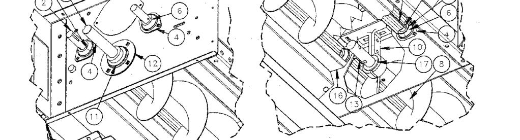
98 98
99 Extra High Capacity Unload System ITEM # PART # DESCRIPTION ALUM METERING EXTRUSION, 93 3/8 FRONT DRIVE SHAFT - METERING ROLL CONNECTION SHAFT - METERING ROLL B /4" FLANGETTE 2-HOLE ZINC REAR SHAFT - METERING ROLL BEARING WOOD SPHERE 1-1/8 62 MM MACH BUSH GA. Zinc AUGER, 9" RH 8' EHC DRYER FRONT DRIVE SHAFT - EXTRA HIGH CAPACITY HANGER BEARING HOLDER 1 1/2" EHC DRYER BEARING 1 1/2" - EXTRA HIGH CAPACITY 1 1/2" FLANGETTE 4-HOLE ZINC - EHC CONNECTION SHAFT - 1 1/2" X 12" EHC REAR DRIVE SHAFT - EXTRA HIGH CAPACITY REAR IDLE SHAFT - EXTRA HIGH CAPACITY FRAME EXTENSION METERING ROLL CUP WOOD BEARING (#B0165) - FOR 1.5 SHAFT WHEEL STOP PAWL CLEANOUT DOOR CABLE WINCH WELDMENT 99
100 100
101 Standard & High Capacity Rear Cross Auger ITEM # PART # DESCRIPTION GEARBOX ASSEMBLY B /4" FLANGETTE 2-HOLE ZINC SPROCKET RC5020 x 1 1/4" BORE SPROCKET RC5020 x 1" BORE IDLER SPROCKET /2" BORE BEARING 1 1/4" INSERT RA103RRB2AG DRYER SPOUT ACCESS COVER CROSS AUGER TROUGH - STD CROSS AUGER TROUGH - HIGH CAPACITY TROUGH END PLATE - STD TROUGH END PLATE - HIGH CAPACITY TROUGH LID - STD TROUGH LID - HIGH CAPACITY STANDARD DISCHARGE HIGH CAPACITY DISCHARGE STANDARD CENTER DISCHARGE HIGH CAPACITY CENTER DISCHARGE SHAFT DRIVE, CROSS AUG U-TR SHAFT IDLE, CROSS AUG U-TR REAR CHAIN GUARD BACK PLATE REAR CHAIN GUARD COVER SIDE CHAIN GUARD BACK PLATE SIDE CHAIN GUARD COVER SIDE CHAIN GUARD SPACER " GEARBOX SHAFT SHIELD - REAR UNLOAD SHAFT SHIELD - REAR REAR CHAIN GUARD SPACER " ROLLER CHAIN - #50 ROLLER CHAIN CONNECTION LINK - #50 TROUGH DISCHARGE COVER - STD TROUGH DISCHARGE COVER - HIGH CAPACITY 101
102 102
103 Extra High Capacity Rear Cross Auger ITEM # PART # N/A DESCRIPTION ROLLER CHAIN #50 BULK ROLLER CHAIN #50 CONN LINK N0511 GEARBOX ASSEMBLY, GRAIN DRYER B /4" FLANGETTE 2-HOLE ZINC SPACER, 1/2" I.D. X 1" O.D. X 7/8" LONG B0197 SPROCKET RC5020 X 1 1/2" BORE SPROCKET RC5020 X 1 1/4" BORE SPROCKET RC5020 X 1" BORE SPROCKET IDLER /2" BORE BEARING 1 1/4" INSERT RA103RRB2AG EHC REAR CROSS AUGER DISCHARGE COVER EHC REAR CROSS AUGER CENTER DISCHARGE SHAFT DRIVE, CROSS AUG U-TR SHAFT IDLE, CROSS AUG U-TR SPACER CHAIN GUARD SIDE 1.25" SHAFT SHIELD GEARBOX REAR DRYER SHAFT SHIELD DRYER UNLOAD CROSS EHC CROSS AUGER END PLATE EHC DRYER SPOUT ACCESS COVER EHC REAR CHAIN GUARD BACK PLATE EHC REAR CHAIN GUARD COVER EHC SIDE CHAIN GUARD BACK PLATE EHC SIDE CHAIN GUARD COVER EHC UNLOAD SHAFT SHIELD EHC CROSS AUGER TROUGH (NRW) EHC CROSS AUGER LID (NRW) EHC REAR CROSS AUGER LFT / RGT DISCHARGE (NRW) SPACER CHAIN GUARD REAR 0.75" 103
104 3/8" LOCK WASHER 3/8" NUT INSERT BEARING FLANGETTE 3/8" x 1 1/4" CARRIAGE BOLT 1/2" x 1 1/2" BOLT HANGER BEARING HOLDER BRACKET / SIDE SKIRT SPLICE 1/2" FLATWASHER HANGER BEARING HOLDER HALF 1/2" LOCK WASHER 1/2" LOCK WASHER 1/2" x 1" BOLT 1/2" NUT 1/2" NUT WOOD HANGER BEARING 104
105 Level Auger Misc. Parts (Garner & Roof Style) CONNECTION SHAFT DRIVE SHAFT 1/2" NUT NOTE: IDLER SHAFT IS AT OPPOSITE END OF DRIVE SHAFT. 1/2" x 2" BOLT (6" & 8" AUGER SIZE) 1/2" x 2 1/2" BOLT (10" & 12" AUGER SIZE) LEVEL AUGER MISC. PARTS (GARNER & ROOF STYLE) DRYER SIZE N/A N/A N/A N/A N/A 12 & & & & & & 32 PART # DESCRIPTION B /4 FLANGETTE 2-HOLE ZINC BEARING 1 1/4 INSERT RA103RRB2AG 1 1/4 WOOD HANGAR BEARING 1 1/2 WOOD HANGAR BEARING 2 WOOD HANGAR BEARING DRIVE SHAFT (6 AUGER) DRIVE SHAFT (8 AUGER) DRIVE SHAFT (10 & 12 AUGER) CONNECTION SHAFT (6 & 8 AUGER) CONNECTION SHAFT (10 AUGER) IDLER SHAFT (6 AUGER) IDLER SHAFT (8 AUGER) IDLER SHAFT (10 AUGER) IDLER SHAFT (12 AUGER) 105
106 IDLER SHAFT AUGER EXTENSION AUGER AUGER DRIVE SHAFT CONNECTION SHAFT TWO HOLE FLANGETTE INSERT BEARING DRYER SIZE 12 & & PART # DESCRIPTION 6 AUGER 6 AUGER 8 AUGER 10 AUGER 6 AUGER 8 AUGER 10 AUGER 10 AUGER 6 EXTENSION AUGER 8 EXTENSION AUGER 10 EXTENSION AUGER 10 EXTENSION AUGER 106
107 DRYER SIZE PART # DESCRIPTION 6 AUGER 6 AUGER 8 AUGER 8 AUGER 10 AUGER 12 AUGER 12 AUGER 10 AUGER 10 AUGER 12 AUGER 12 AUGER 107
:")
108 MANUFACTURED BY NECO A Division of GLOBAL Industries, Inc North 45th Street Omaha, Nebraska TEL: FAX: Toll-free (within Nebraska): Toll-free (outside Nebraska):
Continuous-Flow Grain Dryer
 Continuous-Flow Grain Dryer Standard Controls Assembly / Installation Manual Effective Date: Oct 16, 2013 Publication Number: 7713393 Rev: B ***** HAVE QUESTIONS or NEED HELP?? ***** Before you call...
Axial Flow Fan Owner's & Operator's Manual
 Axial Flow Fan Owner's & Operator's Manual Effective Date: Nov 3, 03 Publication Number: 73 Rev: A Welcome to the growing number of satisfied NECO customers Since 959, NECO equipment has been proudly designed,
Be sure to support the lower section using a crane or setting it on temporary blocks, etc..
 6. INSTALLATION Position Lower Dryer at Location Position the lower dryer section at the final location. Be sure to support the lower section using a crane or setting it on temporary blocks, etc.. Anchor
Be sure to support the lower section using a crane or setting it on temporary blocks, etc..
 9. INSTALLATION Position Lower Dryer at Location Position the lower dryer section at the final location. Be sure to support the lower section using a crane or setting it on temporary blocks, etc.. Anchor
1 and 2 Fan Vision Series Portable Dryers
 1 and 2 Fan Vision Series Portable Dryers Operator s Manual PNEG-1456 Date: 09-29-09 PNEG-1456 2 PNEG-1456 1 and 2 Fan Vision Series Portable Dryers Table of Contents Contents Chapter 1 Safety... 5 Safety
Humidistat-Thermostat
 Humidistat-Thermostat Model # HF _- - - Owner s Manual PNEG-236 Date: 12-02-09 PNEG-236 2 PNEG-236 Humidistat-Thermostat Table of Contents Contents Chapter 1 Safety... 4 Safety Guidelines... 4 Humidistat-Thermostat
3. Turn on the electrical power supply to the dryer, and move the safety disconnect handle mounted on the dryer s upper power box to on.
 DRYER OPERATION - START-UP INITIAL SETUP PARAMETERS Turn the control power switch to on. When the Boot Screen appears touch the START DRYER button. The computer will run a quick check of the system network
Competitor Series Dryers
 Cost Efficient, Competitively Priced, Completely GSI. Competitor Series Dryers "Your Complete Systems Manufacturer." THE COMPETITIVE EDGE GSI Competitor 100 Series grain dryers offer all the latest technological
3. Turn on the electrical power supply to the dryer, and move the safety disconnect handle mounted on the dryer s upper power box to on.
 DRYER OPERATION - START-UP INITIAL SETUP PARAMETERS Turn the control power switch to on. When the Boot Screen appears touch the START DRYER button. The computer will run a quick check of the system network
CENTRIFUGAL FAN Owner's and Operator's Manual (CE Models)
") CENTRIFUGAL FAN Owner's and Operator's Manual (CE Models) ATTENTION Pay close attention when you see this triangular symbol. It will be located throughout this manual and on decals. Obey the Dangers, Warnings
CENTRIFUGAL FAN Owner's and Operator's Manual (CE Models) ATTENTION Pay close attention when you see this triangular symbol. It will be located throughout this manual and on decals. Obey the Dangers, Warnings
Volume MATHEWS COMPANY. Legacy Series L1250 /L1350 /L2550 /L2650 /L2700 /L3100 /L3105 /L4145 /L5175. Operations Manual
 Volume 1 MATHEWS COMPANY Legacy Series L1250 /L1350 /L2550 /L2650 /L2700 /L3100 /L3105 /L4145 /L5175 2011 Mathews Company 500 Industrial Avenue Crystal Lake, IL 60012 USA Toll Free Number: (800) 323 7045
CE Approved Portable Dryer Wiring Diagrams. Model: 1200 Series. Electrical Installation Manual PNEG Version: 1.0. Date: PNEG-2119
 CE Approved Portable Dryer Wiring Diagrams Model: 1200 Series Electrical Installation Manual PNEG-2119 Version: 1.0 Date: 11-01-16 PNEG-2119 All information, illustrations, photos and specifications in
2 & 3 Module DriTek Plus Dryers
 OPERATOR S MANUAL 2 & 3 Module DriTek Plus Dryers Division of ffi Corporation 1004 E. Illinois St. Assumption, IL 62510 PNEG-1540 Date: 09-15-2006 PNEG-1540 CONTENTS INTRODUCTION...4 OPERATING PRECAUTIONS...4
WHEN TROUBLESHOOTING, PERFORM THE STEPS IN ORDER.
 WHEN, PERFORM THE STEPS IN ORDER. BURNER WON T LIGHT Control System 1. Is the main interlock in auto? The burner will not light if the dryer is in manual mode b. No: Switch the main interlock to auto 2.
Always keep this manual in a safe readily accessible location. MODEL SERIAL SERVICE COMPANY TELEPHONE NUMBER
 Always keep this manual in a safe readily accessible location. MODEL SERIAL SERVICE COMPANY TELEPHONE NUMBER For Operating Instructions or Technical Support Call 1-507-886-6666 Last Revision: 1/31/12 Starting
Competitor Series Dryers
 Cost Efficient, Competitively Priced, Completely GSI. Competitor Series Dryers "Your Complete Systems Manufacturer." THE COMPETITIVE EDGE GSI Competitor 100 Series grain dryers offer all the latest technological
Com-Pak Heater Benefits You Can Depend On Com-Pak Models Line Model w/o Model w/ Voltage Thermostat Thermostat Watts Amps (1) (2)
 (2)") Benefits You Can Depend On Dual safety features Primary: power reset thermal switch Secondary: over temperature thermal fuse Heating element style quickly warms your room, and quickly cools when heater
Benefits You Can Depend On Dual safety features Primary: power reset thermal switch Secondary: over temperature thermal fuse Heating element style quickly warms your room, and quickly cools when heater
The Danger signal indicates an immediately hazardous situation which, if not avoided, will result in death or serious injury.
 The Danger signal indicates an immediately hazardous situation which, if not avoided, will result in death or serious injury. The Warning signal alerts you to potential hazards or unsafe practices which,
Air Storm Fans. Air Storm 54 Fiberglass Fan Installation and Operation Manual
 Air Storm 54 Fiberglass Fan Installation and Operation Manual Table of Contents GrowerSELECT General Page... 3 Safety... 4 Warning Labels... 4 Installation... 5 Operation Safety... 5 Maintenance Safety...
Corn Flame Energy Corn Stove Model 3000
 Corn Flame Energy Corn Stove Model 3000 Installation and Operation Guide Read thoroughly before starting installation Save this manual for future reference SAFETY NOTICE If this stove is not properly installed,
Panel Fan Series Operators Manual (Galvanized and Polymer)
") Panel Fan Series Operators Manual (Galvanized and Polymer) 52" Belt Drive, Galvanized Panel Fan with Three Wing Blade IMPORTANT: READ AND SAVE THESE INSTRUCTIONS Read all instructions carefully before
Panel Fan Series Operators Manual (Galvanized and Polymer) 52" Belt Drive, Galvanized Panel Fan with Three Wing Blade IMPORTANT: READ AND SAVE THESE INSTRUCTIONS Read all instructions carefully before
MODULER SQUARE PADDY GRAIN DRYER
 MODULER SQUARE PADDY GRAIN DRYER Models: TWSQ-SERIES TWSQ-07 TWSQ-09 TWSQ-11 TWSQ-13 1 Model Volume (m³) Height (mm) Max gross power (kw) TWSQ -03-1 7,8 3170 82 TWSQ -04-1 9,4 3705 82 TWSQ -05-1 11 4240
Foodservice Equipment Specialists P.O. Box 880 Saco, ME. / U.S.A * FAX (207)
") Foodservice Equipment Specialists P.O. Box 880 Saco, ME. / U.S.A. 04072 877-854-8006 * FAX (207) 283-8080 OPERATIONS AND MAINTENANCE PROCEDURES FOR SERVICE ASSISTANCE U.S. AND CANADA CALL: 1-877-854-8006
Foodservice Equipment Specialists P.O. Box 880 Saco, ME. / U.S.A. 04072 877-854-8006 * FAX (207) 283-8080 OPERATIONS AND MAINTENANCE PROCEDURES FOR SERVICE ASSISTANCE U.S. AND CANADA CALL: 1-877-854-8006
Air Storm Fans. Air Storm 24 Fiberglass Fan Installation and Operation Manual
 Air Storm 24 Fiberglass Fan Installation and Operation Manual Hog Slat Inc. Newton Grove, NC USA May 2015 Table of Contents GrowerSELECT General Page...3 Safety...4 Warning Labels...4 Installation...5
PRACTICAL USER S GUIDE FOR THE ELECTRIC STOVE
 PRACTICAL USER S GUIDE FOR THE ELECTRIC STOVE MODEL NUMBERS: 23 Electric Stove Quality checked by: Valued Customer, We are pleased that you have chosen to purchase an electric stove manufactured by Dimplex
SPA BLOWER OWNER'S MANUAL XXXX, XXXX, XXXX, XXXX, XXXX, XXXX fax
 SPA BLOWER OWNER'S MANUAL 80015-XXXX, 80016-XXXX, 80017-XXXX, 80018-XXXX, 80019-XXXX, 80020-XXXX fax 888.610.3839 2015 323300-015 6/15 THIS PAGE INTENTIONALLY LEFT BLANK. 2 Operating Instructions and Parts
USER S MANUAL BUCKET FAN SERIES BUCKET FAN WHISPER SERIES
 USER S MANUAL BUCKET FAN SERIES BUCKET FAN WHISPER SERIES Bucket Fan 420 Bucket Fan 1055 Bucket Fan 1460 420 1055 1460 2 Bucket Fan CONTENT INTRODUCTION 3 USE 3 WHAT S INCLUDED IN THE BOX 3 DESIGNATION
IMPORTANT INSTRUCTIONS
 IMPORTANT INSTRUCTIONS W Fan Force Electric Space Heater DANGER ELECTRIC SHOCK OR FIRE HAZARD Figure 1 Covers all W Series models WARNING Read Carefully - These instructions are written in an effort to
Auto Opening with Pressure Readout 15 x15 & 16 x20 Heat Transfer Machines
 S-450P & S-650P Auto Opening with Pressure Readout 15 x15 & 16 x20 Heat Transfer Machines OWNER S MANUAL S-650P shown For Customer Service, Call 1-800-835-0606 or Visit www.hixcorp.com CONTENTS Receiving
User s Manual and Warranty Information for Counterweighted Chain Drive ThyssenKrupp Access
 II User s Manual and Warranty Information for Counterweighted Chain Drive ThyssenKrupp Access Part #2139703 Rev. G II Table of Contents Introduction...3 Elevator Overview...4 Description of Features...5-7
1 HP Air Mover. Owner s Manual
 1 HP Air Mover Owner s Manual WARNING: Read carefully and understand all ASSEMBLY AND OPERATION INSTRUCTIONS before operating. Failure to follow the safety rules and other basic safety precautions may
IMPORTANT SAFETY INFORMATION:
 Owner s Manual Model DS7420 DS7425DLX IMPORTANT SAFETY INFORMATION: Always read this manual first before attempting to install or use this stove. For your safety, always comply with all warnings and safety
Retrofit Instructions for Tower Dryer Moisture Sampler Blower Kit
 Retrofit Instructions for Tower Dryer Moisture Sampler Blower Kit Installation Manual PNEG-1982 Date: 03-26-15 PNEG-1982 2 PNEG-1982 Retrofit Instructions for Tower Dryer Moisture Sampler Blower Kit Table
Owner s Manual Refrigerated Compressed Air Dryers Model F-100
 Owner s Manual Refrigerated Compressed Air Dryers Model F-100 Read carefully before attempting to assemble, install, operate or maintain the product described. Protect yourself and others by observing
PANEL FAN SERIES OPERATORS MANUAL (Galvanized and Polymer)
") PANEL FAN SERIES OPERATORS MANUAL (Galvanized and Polymer) Galvanized Panel Fan IMPORTANT: READ AND SAVE THESE INSTRUCTIONS Read all instructions carefully before attempting to assemble, install, operate
PANEL FAN SERIES OPERATORS MANUAL (Galvanized and Polymer) Galvanized Panel Fan IMPORTANT: READ AND SAVE THESE INSTRUCTIONS Read all instructions carefully before attempting to assemble, install, operate
CAR-MON DUST COLLECTORS SERIES 207, 2410, 3015
 INSTALLATION-OPERATION-MAINTENANCE CAR-MON DUST COLLECTORS SERIES 207, 2410, 3015 TEFC 3 phase motor Outlet duct Fan wheel housing Inlet duct connection After filter transition Optional after filter unit
Air Storm Fans. Air Storm 18 Fiberglass Fan Installation and Operation Manual
 Air Storm 18 Fiberglass Fan Installation and Operation Manual Table of Contents GrowerSELECT General Page...3 Safety...4 Warning Labels...4 Installation...5 Operation Safety...5 Maintenance Safety...5
AquaSaver DISPOSER CONTROL CENTER Installation Manual. Model AS-101K
 AquaSaver DISPOSER CONTROL CENTER Installation Manual Model AS-1K The Danger signal indicates an immediately hazardous situation which, if not avoided, will result in death or serious injury. The Warning
PRACTICAL USER S GUIDE FOR THE DIMPLEX PURIFIRE ELECTRIC STOVE
 PRACTICAL USER S GUIDE FOR THE DIMPLEX PURIFIRE ELECTRIC STOVE Serial Number Quality checked by: Model Number CAT Number Valued Customer, We are pleased that you have chosen to purchase an electric fireplace
Owner s Manual Refrigerated Compressed Air Dryers Models F-200, 250, 300 & F350
 Owner s Manual Refrigerated Compressed Air Dryers Models F-200, 250, 300 & F350 Read carefully before attempting to assemble, install, operate or maintain the product described. Protect yourself and others
INSTRUCTION MANUAL. Full Size Gas Convection Oven
 INSTRUCTION MANUAL Full Size Gas Convection Oven This manual contains important information regarding your unit. Please read this manual thoroughly prior to equipment set-up, operation and maintenance.
OPERATIONS MAINTENANCE MANUAL
 OPERATIONS MAINTENANCE MANUAL COOK & HOLD OVEN SYSTEMS WITTCO MODEL NUMBERS 1300-AD-SS 1300-AD-SS-SPLIT LIMITED WARRANTY Wittco warrants the Products that it manufactures to be free from defects in materials
Owner s Manual Refrigerated Compressed Air Dryer Model F-50
 Owner s Manual Refrigerated Compressed Air Dryer Model F-50 Read carefully before attempting to assemble, install, operate or maintain the product described. Protect yourself and others by observing all
Owner s Manual Refrigerated Compressed Air Dryers Models F-3528, F-3529, F-3530, F-3531 & F-3532
 Owner s Manual Refrigerated Compressed Air Dryers Models F-3528, F-3529, F-3530, F-3531 & F-3532 Read carefully before attempting to assemble, install, operate or maintain the product described. Protect
ELECTRIC FIREPLACE HEATER WITH SINGLE GLASS DOOR
 ELECTRIC FIREPLACE HEATER WITH SINGLE GLASS DOOR Model 91797 ASSEMBLY and Operating Instructions Visit our website at: http://www.harborfreight.com Read this material before using this product. Failure
Digital Moisture Control Thermostat
 Digital Moisture Control Thermostat Installation and Operation Manual PNEG 1711 Date: 2009 PNEG - 1711 Page 1 of 22 06/30/2009 READ THESE INSTRUCTIONS BEFORE INSTALLATION and OPERATION. SAVE FOR FUTURE
Part No Revised: June TS1 TOASTER SYSTEM Instruction Manual Models # 5700 AND # 5700SF
 Part No. 44162 Revised: June 2006 TS1 TOASTER SYSTEM Instruction Manual Models # 5700 AND # 5700SF SAFETY PRECAUTIONS 2 TOASTER SYSTEM INSTALLATION CHECKING SHIPMENT Unpack the unit from the shipping container
Mobile Hot Food Merchandiser Series. Series: MHB Operation Manual
 Mobile Hot Food Merchandiser Series Series: MHB Operation Manual BKI LIMITED WARRANTY Grandview Drive Simpsonville, SC 0 USA () - Toll Free: (00) - Fax: () - WHAT IS COVERED WHO IS COVERED COVERAGE PERIOD
INSTALLATION GUIDE Dual Fuel Ranges
 INSTALLATION GUIDE Dual Fuel Ranges Contents Wolf Dual Fuel Ranges......................... 3 Safety Instructions............................ 4 Dual Fuel Range Specifications.................. 5 Dual Fuel
DBF 4XL Dryer Booster Fans
 Installation and Operation Manual Item #: 401315 Rev Date: 050814 DBF 4XL Dryer Booster Fans DBF4XL Kit Includes: Dryer Booster Fan, 1 pc Fan Mounting Bracket and Hardware, 1 pc Wall Label (Mount on wasll
Installation & Maintenance Instructions
 Portable High Temperature Blower Attention: Do not operate this heater in explosive areas. Installation & Maintenance Instructions Dear Owner, Congratulations! Thank you for purchasing this new heater
High-Velocity Floor Fan
 High-Velocity Floor Fan Owner s Manual WARNING: Read carefully and understand all ASSEMBLY AND OPERATION INSTRUCTIONS before operating. Failure to follow the safety rules and other basic safety precautions
Industrial Vacuums, Inc
 Instructions/Spare Parts Manual Nilfisk Model GWD255 Drum Top Vacuum CAUTION: This Nilfisk vacuum cleaner is not to be used in explosion-hazardous areas, as serious injury could result. Under no circumstances
XPS-ProDry User s Guide Dryer Base
 XPS-ProDry User s Guide XPS-ProDry User s Guide Dryer Base For Use with Inkjet Imaging Systems Manual Part#: M-3120 Revision: August 2005 XPS-ProDry User s Guide Written by Frank Mauri & John Brand Published
TMC. Installation and Operation Manual TMC. Temperature and Pressure Monitoring for Heating and Cooling Applications. Temperature Monitoring Control
 Installation and Operation Manual Temperature and Pressure Monitoring for Heating and Cooling Applications Temperature Monitoring Control VALVE OPEN ALARM System= 128 o F Alarm At= 130 o F RESET /BACK
Service Parts, Kits and Accessories
 The parts identification guides on the following pages have been designed to give a quick reference to component parts used on pilot ignition agricultural building heaters. The guides identify components
Burn Easy Installation Instructions LP or Natural Gas Fired Units. Cremator Setup:
 Burn Easy Installation Instructions LP or Natural Gas Fired Units Cremator Setup: 1. Place cremator, outdoor on a solid base consisting of concrete or gravel. Keep this site free of all vegetation. Combustibles
Air Cleaning Equipment, Inc. 303 N. Main St. Broadway, NC iers.com
 Read and Save These Instructions Horizon Galaxy - Installation and Operations Manual Air Cleaning Equipment, Inc. 303 N. Main St. Broadway, NC 27505 www.horizondehumidif iers.com 1 Safety Notes: The Horizon
RK / RK Methane Detector Operator s Manual
 61-1006RK / 61-0192RK Methane Detector Operator s Manual Part Number: 71-0228RK Revision: 0 Released: 10/29/18 www.rkiinstruments.com WARNING Read and understand this instruction manual before operating
WATLOW IND. WATROD Modular Duct Heater Installation & Maintenance Manual I&M NUMBER: Page: 1 Date:6/11/2008 Rev: 2
 I&M NUMBER: 316-42-15-1 Page: 1 _ Pre Installation Check to make sure that heater received is the same as that ordered. Elements may come in contact with each other during shipment. Minor adjustments to
IMPORTANT SAFETY INFORMATION:
 Owner s Manual Model CUH05B31T IMPORTANT SAFETY INFORMATION: Always read this manual first before attempting to install or use this heater. For your safety, always comply with all warnings and safety instructions
User s Manual and Operating Instructions
 User s Manual and Operating Instructions Model Numbers: CL-30P-DDF, CL-20F-DDF, CL-24O-DDF, CL-30-DDF READ AND SAVE THESE INSTRUCTIONS IMPORTANT: Read and understand all of the directions in this manual
TURBO Hooded Fans. Installation & Operator s Manual (14, 18, & 24 Direct Drive)
") TURBO Hooded Fans Installation & Operator s Manual (14, 18, & 24 Direct Drive) August 1996 MV1089B8 WARRANTY INFORMATION Chore-Time Equipment warrants each new product manufactured by it to be free from
TURBO Hooded Fans Installation & Operator s Manual (14, 18, & 24 Direct Drive) August 1996 MV1089B8 WARRANTY INFORMATION Chore-Time Equipment warrants each new product manufactured by it to be free from
Beacon 800 Gas Monitor Operator s Manual
 Beacon 800 Gas Monitor Operator s Manual Part Number: 71-0037RK Revision: F Released: 4/18/17 www.rkiinstruments.com Product Warranty RKI Instruments, Inc. warrants gas alarm equipment sold by us to be
Portable Dryer Touch Screen Controls
 Portable Dryer Touch Screen Controls and Reference Manual PNEG 1509 PNEG 1509 Date: 1 23 08 Reference Table of Contents TABLE OF CONTENTS DRYER SAFETY & DRYER INFORMATION...4 SPECIAL SETUP SCREENS...5
SWP. (Models SWP08 through SWP20) IMPORTANT! Read before proceeding! OPERATION & MAINTENANCE MANUAL
 IMPORTANT! Read before proceeding! OPERATION & MAINTENANCE MANUAL") SWP (Models SWP08 through SWP20) OPERATION & MAINTENANCE MANUAL IMPORTANT! Read before proceeding! Read carefully before attempting to assemble, install, operate or maintain the product described. Protect
SWP (Models SWP08 through SWP20) OPERATION & MAINTENANCE MANUAL IMPORTANT! Read before proceeding! Read carefully before attempting to assemble, install, operate or maintain the product described. Protect
Panel Fan Series Operators Manual (Galvanized and Polymer)
") Panel Fan Series Operators Manual (Galvanized and Polymer) Galvanized Panel Fan with Three Wing Blade IMPORTANT: READ AND SAVE THESE INSTRUCTIONS Read all instructions carefully before attempting to assemble,
Panel Fan Series Operators Manual (Galvanized and Polymer) Galvanized Panel Fan with Three Wing Blade IMPORTANT: READ AND SAVE THESE INSTRUCTIONS Read all instructions carefully before attempting to assemble,
Custom Control Systems Inc. Ellis Dryer Control Configuration and Operation Manual
 Ellis Dryer Control Configuration and Operation Manual Revised 1/19/2004 Table of Contents 1 Introduction... 7 1.1 Hardware Specifications... 7 1.2 Software Features... 7 1.3 Warranty... 8 1.3.1 Terms...
OPERATING MANUAL Gfp 255C Please read this manual carefully before operating!
 OPERATING MANUAL Gfp 255C Please read this manual carefully before operating! Unpacking, assembly, and operating videos are available at www.gfpsmoothstart.com 1 Table of Contents Gfp 255C March 2015 Contents
Instruction Manual. Dogeroo, Super Dogeroo, and Mini Dogeroo
 Instruction Manual Dogeroo, Super Dogeroo, and Mini Dogeroo Model No. 8102, 8103, 8108 10700 Medallion Drive, Cincinnati, Ohio 45241-4807 USA Part No. 87793 SAFETY PRECAUTIONS Page 2 INSTALLATION INSTRUCTIONS
Deluxe Vane Axial Heater
 Deluxe Vane Axial Heater MODEL # VH - - - D (HIGH FIRE) MODEL # VL - - - D (LOW FIRE) Owner's Manual MANUAL # PNEG-86 VANE AXIAL HEATER CHECK LIST Deluxe Vane Axial Heater!OK. All wire connections. Spark
SERVICE AND INSTALLATION MANUAL MODELS HDO(H) OIL FOR YOUR SAFETY
 OIL FOR YOUR SAFETY") Bousquet Technologies Inc. 2121, Nobel, Ste Julie, Quebec, Canada, J3E1Z9 SERVICE AND INSTALLATION MANUAL MODELS HDO(H) OIL Oil-Fired air heater for industrial and commercial use. FOR YOUR SAFETY Do not
Bousquet Technologies Inc. 2121, Nobel, Ste Julie, Quebec, Canada, J3E1Z9 SERVICE AND INSTALLATION MANUAL MODELS HDO(H) OIL Oil-Fired air heater for industrial and commercial use. FOR YOUR SAFETY Do not
Ultra Clean LAMBTON CONVEYOR LIMITED. Installation and Operation Manual ONE SOURCE ONE SOLUTION
 Ultra Clean Installation and Operation Manual LAMBTON CONVEYOR LIMITED ONE SOURCE 1 Contents Warranty... 4 Section 1. Safety... 5 Section 2. Decals... 8 Section 3. Product Information... 9 Ultra Clean
Level Alarm Control. Blender Accessories U S E R G U I D E UGB
 www.conairgroup.com U S E R G U I D E UGB015-1007 Level Alarm Control Blender Accessories Corporate Office: 724.584.5500 Instant Access 24/7 (Parts and Service): 800.458.1960 Parts and Service: 814.437.6861
Henny Penny Island Warmer Model HMI-103 Model HMI-105 TECHNICAL MANUAL
 Henny Penny Island Warmer Model HMI-103 Model HMI-105 TECHNICAL MANUAL THIS PAGE INTENTIONALLY LEFT BLANK. Section TABLE OF CONTENTS Page Section 1. TROUBLESHOOTING... 1-1 1-1. Introduction... 1-1 1-2.
USER GUIDE. This manual covers the description, cautions, operation and maintenance of Super Vac confined space electric ventilators CONTENTS
 VENTILATOR USER GUIDE MODEL HF124 USER GUIDE This manual covers the description, cautions, operation and maintenance of Super Vac confined space electric ventilators Please take the time to read this manual
RK/ RK Combustible Gas Detector Operator s Manual
 61-1003RK/61-0190RK Combustible Gas Detector Operator s Manual Part Number: 71-0120RK Revision: 0 Released: 2/11/11 www.rkiinstruments.com WARNING Read and understand this instruction manual before operating
CUTMASTER Strip Cutting Machine
 EASTMAN THE EASTMAN CUTMASTER Strip Cutting Machine WARNING Safety glasses must be worn at all times when operating or servicing this equipment. Instruction Manual & Illustrated Parts List Please read
DH07, DH07A /DH08, DH08A CONVECTED AIR DISH HEATERS
 DH07, DH07A /DH08, DH08A CONVECTED AIR DISH HEATERS DH07 shown INSTALLATION, OPERATION & MAINTENANCE MANUAL Manual P/N 92448 Rev. G 04/02/2009 Copyright 1998 Aladdin Temp-Rite Changes may be made to the
Instruction Manual. Nacho Cheese Dispenser and Warmer
 Instruction Manual Nacho Cheese Dispenser and Warmer 10700 Medallion Drive, Cincinnati, Ohio 45241-4807 USA 2013 Gold Medal Products Co. Part No. 36060 SAFETY PRECAUTIONS Page 2 INSTALLATION INSTRUCTIONS
USER'S MANUAL PGE Single Package Rooftop
 USER'S MANUAL PGE Single Package Rooftop Gas Heating/Electric Cooling Units Sizes 036-150 3 to 12-1/2 Tons NOTE TO INSTALLER: This manual should be left with the equipment owner. WARNING: If the information
DUAL VOLTAGE REFRIGERATORS 220/240 VOLTS AC AND 12/24 VOLTS DC INSTALLATION AND OWNER S MANUAL
 DUAL VOLTAGE REFRIGERATORS 220/240 VOLTS AC AND 12/24 VOLTS DC INSTALLATION AND OWNER S MANUAL Service Information If service or parts are required, contact the nearest Norcold Service Center. To find
RK-03 Hydrogen Detector Operator s Manual
 61-1001RK-03 Hydrogen Detector Operator s Manual Part Number: 71-0371 Revision: P1 Released: 5/26/15 www.rkiinstruments.com WARNING Read and understand this instruction manual before operating detector.
IMPORTANT SAFETY INFORMATION:
 Owner s Manual Model DCS19W IMPORTANT SAFETY INFORMATION: Always read this manual first before attempting to install or use this stove. For your safety, always comply with all warnings and safety instructions
Control Panel For Water Wash Hoods AM2
 Control Panel For Water Wash Hoods AM2 For further information Call: (919) 554-1025 Or Fax: (919)554-1525 Aqua-Matic 117 Franklin Park Ave. Youngsville, NC 27506 TABLE OF CONTENTS AQUA-MATIC LIMITED WARRANTY
CYLINDER NOT INCLUDED
 OPERATING INSTRUCTIONS AND OWNER S MANUAL Model # HS125NG / MH125LP / HS125LP READ INSTRUCTIONS CAREFULLY: Read and follow all instructions. Place instructions in a safe place for future reference. Do
MODEL HS115-3, HS115-4 & HS115-5 WIRING DIAGRAM ADDENDUM
 TJERNLUND PRODUCTS, INC. 1601 Ninth Street White Bear Lake, MN 55110-6794 PHONE (800) 255-4208 (651) 426-2993 FAX (651) 426-9547 Visit our web site www.tjernlund.com MODEL HS115-3, HS115-4 & HS115-5 WIRING
Fire Bowls and Fire Bowl Inserts (Automated Operation) Operating and Maintenance Instructions
 Operating and Maintenance Instructions") Table of Contents Section 1: Gas and Electric Requirements... 1 Section 2: Installation... 2 Section 3: Burner Setup and Adjustment... 8 Burner Adjustment... 9 Section 4: Maintenance... 10 Section 5: Operation...
Table of Contents Section 1: Gas and Electric Requirements... 1 Section 2: Installation... 2 Section 3: Burner Setup and Adjustment... 8 Burner Adjustment... 9 Section 4: Maintenance... 10 Section 5: Operation...
User Manual Box Exhaust Fan Series (Belt Drive)
") User Manual Box Exhaust Fan Series (Belt Drive) 36" Box Exhaust Fan with Three Wing Blade Box with Aluminum Shutter 54" Box with Cone 800-779-3267 sales@schaeferfan.com www.schaeferfan.com 2013 Schaefer
User Manual Box Exhaust Fan Series (Belt Drive) 36" Box Exhaust Fan with Three Wing Blade Box with Aluminum Shutter 54" Box with Cone 800-779-3267 sales@schaeferfan.com www.schaeferfan.com 2013 Schaefer
FEED SYSTEM OPERATING INSTRUCTIONS THIS SHOULD NOT BE REFERENCED FOR INSTALLATION OR MAINTENANCE
 FEED SYSTEM OPERATING INSTRUCTIONS THIS SHOULD NOT BE REFERENCED FOR INSTALLATION OR MAINTENANCE Hog Slat Inc. Newton Grove, NC USA August 2017 1 Table of Contents Safety Information... 3 General Safety
AXIAL HEATER - CSA INSTALLATION & OPERATINGMANUAL. P/N Rev 0 NATURAL GAS LIQUID PROPANE VAPOR PROPANE
 AXIAL HEATER - CSA INSTALLATION & P/N 782014 Rev 0 NATURAL GAS LIQUID PROPANE VAPOR PROPANE CH18T-NGE CH18T-VPGE CH24T-NGEM CH24T-LPGE / LPGEM CH24T-VPGE CH28T-NGEM CH28T-LPGE / LPGEM CH28T-VPGE OPERATINGMANUAL
SECTION 1-1 SAFETY PRECAUTIONS
 SECTION 1-1 SAFETY PRECAUTIONS Rotary Dough Feeders (RDF s) are designed and built to operate as safely as possible. However, if precautions and procedures explained in this manual are not followed at
Freightliner Refrigerator Troubleshooting Guide For (TJ18F) (TJ22F) (TJ18FP3)
 (TJ22F) (TJ18FP3)") www.dometic.com Freightliner Refrigerator Troubleshooting Guide For Before initiating troubleshooting, the following equipment is recommended: Multimeter, 20 gauge (min) wires to use as jumpers, and 12Vdc
www.dometic.com Freightliner Refrigerator Troubleshooting Guide For Before initiating troubleshooting, the following equipment is recommended: Multimeter, 20 gauge (min) wires to use as jumpers, and 12Vdc
 INSTALLATION INSTRUCTIONS & USE & CARE GUIDE 01A/02A Series Models 01A/02A Series Models RANGE HOOD LOCATION 1. The range hood must be installed just above the cooktop. 2. The minimum distance from the
INSTALLATION INSTRUCTIONS & USE & CARE GUIDE 06E Series Model 06E Series Model RANGE HOOD LOCATION 1. The range hood must be installed just above the
 INSTALLATION INSTRUCTIONS & USE & CARE GUIDE 06E Series Model 06E Series Model RANGE HOOD LOCATION 1. The range hood must be installed just above the cooktop. 2. The minimum distance from the cooking surface
INTELLI-VAC 14 INTELLI-VAC 18
 INTELLI-VAC 14 INTELLI-VAC 18 INTRODUCTION OPERATING & MAINTENANCE INSTRUCTIONS This operator s book has important information for the use and safe operation of this machine. Read this book carefully before
Smart IR Sensor. Installation and Operation Manual PNEG Date: PNEG-1640
 Smart IR Sensor Installation and Operation Manual PNEG-1640 Date: 12-21-11 PNEG-1640 2 PNEG-1640 Smart IR Sensor Table of Contents Contents Chapter 1 Safety...4 Safety Guidelines...4 Chapter 2 Application...6
READ AND SAVE THESE INSTRUCTIONS READ CAREFULLY BEFORE ATTEMPTING TO ASSEMBLE, INSTALL, OPERATE OR MAINTAIN THE PRODUCT DESCRIBED. PROTECT YOURSELF AN
 READ AND SAVE THESE INSTRUCTIONS READ CAREFULLY BEFORE ATTEMPTING TO ASSEMBLE, INSTALL, OPERATE OR MAINTAIN THE PRODUCT DESCRIBED. PROTECT YOURSELF AND OTHERS BY OBSERVING ALL SAFETY INFORMATION. FAILURE
PRACTICAL USER S GUIDE FOR THE SUB-COMPACT STOVE MODEL NUMBER: CS1205
 PRACTICAL USER S GUIDE FOR THE SUB-COMPACT STOVE MODEL NUMBER: CS1205 Serial Number Quality checked by: Model Number CAT Number Valued Customer, We are pleased that you have chosen to purchase an electric
Foodservice Equipment Specialists P.O. Box 880 Saco, ME. / U.S.A * FAX (207)
") Foodservice Equipment Specialists P.O. Box 880 Saco, ME. / U.S.A. 04072 877-854-8006 * FAX (207) 283-8080 OPERATIONS AND MAINTENANCE PROCEDURES FOR SERVICE ASSISTANCE U.S. AND CANADA CALL: 1-877-854-8006
Foodservice Equipment Specialists P.O. Box 880 Saco, ME. / U.S.A. 04072 877-854-8006 * FAX (207) 283-8080 OPERATIONS AND MAINTENANCE PROCEDURES FOR SERVICE ASSISTANCE U.S. AND CANADA CALL: 1-877-854-8006