TwinTemp Hydronic Heating/ Water Heating Operating Instructions
|
|
|
- Leon Barnett
- 6 years ago
- Views:
Transcription


1 TwinTemp Hydronic Heating/ Water Heating Operating Instructions For maximum heat and hot water output, it is recommended to use the LPG mode of operation in addition to the 120 volt electric element. Electric element operation should be used for minimal hot water demand such as washing hands or dishes. It is not necessary to have the water system filled to use the space heating system, but the heating system must be filled with anti-freeze. To Start Up System: v Turn on the propane supply. v Turn on 12 volt power switch on the right side of the TwinTemp cabinet. v Turn on 12 volt power switch on coach, if applicable. v Burner will start-up and system will be up to operating temperature in approximately minutes depending on position of Summer/winter valve. 3UMMER 0OSITION Summer Operation Position Summer/Winter valve in Summer position. When the space heating function of the TwinTemp is not needed, the heated anti-freeze should not be circulated to the blowers. To prevent this circulation, the Summer/Winter by-pass valve should be turned ¼ turn. When heating is again needed, this valve handle should be turned ¼ quarter turn from the Summer position to the Winter position. This adjustment should only be needed twice a year for summer/ winter operation. 7INTER For Space Heating: 0OSITION Position Summer/Winter valve in Winter position. Turn on main coach thermostat and set to desired temperature. When the system reaches set temperature the blowers will turn on and heat is delivered. When room reaches set temperature, the pump and blowers for that zone will go off. If tank temperature is below set temperature the burner will stay on until tank reaches set temperature. NOTE: the heat register blowers will not activate if the tank temperature is below 160 F. This assures that the hot water function takes priority under heavy usage conditions. Blowers will resume operation when tank returns to operating temperature. For Hot Water TwinTemp unit and water system pump must be turned on or connect to city water system. Turn on hot water tap. Note: During heavy heat and hot water demand, the hot water system takes priority and the heat register blowers may shut off briefly to maintain hot water supply. Hot water temperature is factory set at approximately 120 degrees. To change temperature, consult the operating manual. Once the tank reaches set temperature (5-15 minutes after system is turned on), continuous hot water is delivered when any tap is opened. Delivery temperature is determined by the setting of tempering valve Warning: this valve is factory set at about 120 F. adjusting temperature any higher could result in severe injury due to scalding. Tank thermostat turns pump 1 and burner on automatically when tank temperature starts to drop. Antifreeze circulates from burner and back to tank as it heats. Burner remains in high fire and gas modulates burner to low burn until set temperature is attained. When set temperature is reached, burner and pump shut down and system returns to stand-by mode.
2 Winter Mode Hot Water Production During winter operation if the system has been dormant for more than 20 minutes turn on interior thermostat to call for heat. When the heat register blowers come on turn off thermostat and turn on hot water tap. Preheating the system is required in winter mode for hot water production due to 3 gallons of cold fluid in the hydronic loop suddenly being returned to the TwinTemp tank lowering the fluid (boiler antifreeze) temperature required for hot water production. Once fluid temperature reaches set temperature the system will make continuous hot water. To Use With 110 Volt Heating Element Turn on 110 volt element switch located inside coach. Let the unit heat up for a minimum of minutes. Note: In the 110 volt mode of operation the electric element supplies the heat until demand exceeds its capacity at which time gas burner automatically ignites. The TwinTemp Jr. is equipped with one 110 VAC electric heating element. The element provides limited amounts of hot water or space heating, such as washing hands or dishes. The electric element can be used with or without the propane burner, but for continuous hot water or space heat, the propane burner must be used. To operate, turn the 110 volt switch on in the coach. For small amounts of hot water only, there is no need to turn the 12 volt power on to the TwinTemp. However, if space heat is required in very cold weather, the 12 volt switch should be turned on. If there is a higher demand for heat than the 110 volt element(s) can provide, the propane burner will activate automatically. For best operation, turn the 110 volt element on about 30 minutes before turning 12 volt switch on. This allows the tank to come up to temperature utilizing the electric element before the burner can activate. This will help conserve propane Routine Maintenance All faucet aerators and showerhead screens in the coach should be cleaned regularly. It is recommended that the TwinTemp be inspected by a qualified service technician at least once a year. Particular attention should be paid to the following: Be sure that the air inlet openings and flue area are clear of any debris or obstructions (leaves, bugs, nests, spider webs etc.). Be sure nothing is stored against the unit that would block air or access. Inspect boiler anti-freeze level in reservoir tank. Top off if necessary with a 50/50 mix of specified boiler anti-freeze and water. Check that heater mounting is still secure to the coach. Tighten if necessary. Visually inspect wiring and hoses. Be sure there is no chafing of the insulation. Drain boiler antifreeze every two years and replace with new. (system holds approximately 6 gallons of a 50/50 boiler antifreeze/water mix) Inspect for evidence of antifreeze leaks at internal and external plumbing connections and correct of needed.
3 PrecisionTemp TwinTemp-2 / Junior Service Pack Please read the enclosed PrecisionTemp Warranty Procedure Policy and contact PrecisionTemp PRIOR to proceeding with service. 11 Sunnybrook Drive - Cincinnati, Ohio USA Sunnybrook Drive - Cincinnati, Ohio USA ybrook Drive - Cincinnati, Ohio USA NOTE: This manual covers both TwinTemp models and drawings illustrate the two zone TwinTemp-2. These drawings also illustrate the Junior model with the exception of components related to zone 2. Tankless Hot Water and Temperature Control Specialists Rev 6/15/
4 NOTICE Before proceeding with any repairs or parts replacements on the TwinTemp check the following: - Is the coolant level in the tank up to the bottom of the fill cap? - Is the power turned on and at least 11.5 VDC under load? - Is the gas supply turned on? - Is there any by-passes open, preventing proper circulation of coolant? - Is the flue pipe blocked? - Is there adequate combustion air in the TwinTemp Compartment? - Are there any service codes? - Are the thermostats turned on? - Are there any loose wires or kinked pipes? If after checking the above, the problem still exists, it is advised to call PrecisionTemp to assist in troubleshooting. In any event, Precision Temp must be contacted prior to performing any warranty work. See the PrecisionTemp TwinTemp Warranty Procedure Policy prior to performing work. Call :00 am to 5:00 pm Eastern Time weekdays After hour s technical service- Monday thru Friday 6-9 pm, Saturday 9am-3pm ET Rev 6/15/
5 Table of Contents - Warranty Policy Procedure - Sequence of Operation - Component Illustration - Control Board Layout - Troubleshooting Guide - Electrical, Plumbing & Installation Schematics - Service Codes - Service Bulletins and Charts - Installation Manual - Start-up Procedure - Replacement Parts List Rev 6/15/
6 PrecisionTemp TwinTemp Warranty Procedure Policy The following procedure must be followed to implement the PrecisionTemp Manufacturer s Limited Parts and Warranty. Please refer to the Manufacturer s Limited Parts and Warranty for full terms. To Make a Warranty Claim 1) When possible, contact PrecisionTemp prior to service being performed. The technician must call or prior to performing work. NO work should be preformed prior to calling PrecisionTemp. This work would be considered unbillable time and could void the warranty. If it is known in advance that warranty work must be done on PrecisionTemp equipment outside of PrecisionTemp s normal business hours, (9:00 AM 6:00 PM Eastern time), call the above numbers in advance for a phone number of a PrecisionTemp technician to assist you after hours. 2) If it is known in advance that a part is needed for the service, the service call must not be made until part is on-site. 3) The equipment serial number MUST be on any and all paper work pertaining to the warranted product i.e.: Invoices, Work Orders, Tech Notes, and RGA s. 4) Any parts replaced under warranty must be returned to PrecisionTemp within 15 (fifteen) days of claim. 5) Any parts being returned to PrecisionTemp MUST have an RGA number. If an RGA number was not included with the warranty replacement part the service agency must call PrecisionTemp to obtain an RGA number before returning the part. 6) Hourly rate and travel expense must be approved in advance of work being performed. Under no circumstances will PrecisionTemp pay overtime fees. 7) All warranty invoices must be accompanied by copies of the technician s work sheets that details the service performed and hours worked. PrecisionTemp will cover warranty work done only on products manufactured by PrecisionTemp for defects with the product, not problems related to the coach systems or installation or related equipment issues such as: Improper water pressure. Improper installation including blocked access to heater access panel. Improper voltage to unit. Cold water bypass. Improper power hookup or power turned off. Undersized gas line or low gas pressure. Blocked air supply. Peripheral equipment such as water pumps, faucet, batteries, etc. Sludge buildup or blockage in hydronic plumbing. Warranty coverage is based on PrecisionTemp s warranty policy. PrecisionTemp may, at times, arrange service as a courtesy to the customer. This does not necessarily mean that PrecisionTemp is responsible for the charges. PrecisionTemp will not pay for additional time required to gain access to its equipment or the technician not being given access to equipment in a reasonable timeframe. PrecisionTemp reserves the right to accept or deny warranty claims based on the above policy. Rev 6/15/
7 IMPORTANT INFORMATION The TwinTemp system uses Propylene Glycol antifreeze, high temperature, non toxic with inhibitors for copper and aluminum in a 50/50 mix with water. PrecisionTemp requires Rhogard boiler antifreeze with pro-tek 922 inhibitors for proper protection. Do not use Propylene Glycol antifreeze which is pre mixed, standard RV antifreeze or antifreeze without proper inhibitors. WARNING! DO NOT MIX Propylene Glycol antifreeze and Ethylene Glycol antifreeze. They are incompatible and will turn into a heavy sludge when mixed. Contact PrecisionTemp if Rhogard is not available locally Rev 6/15/
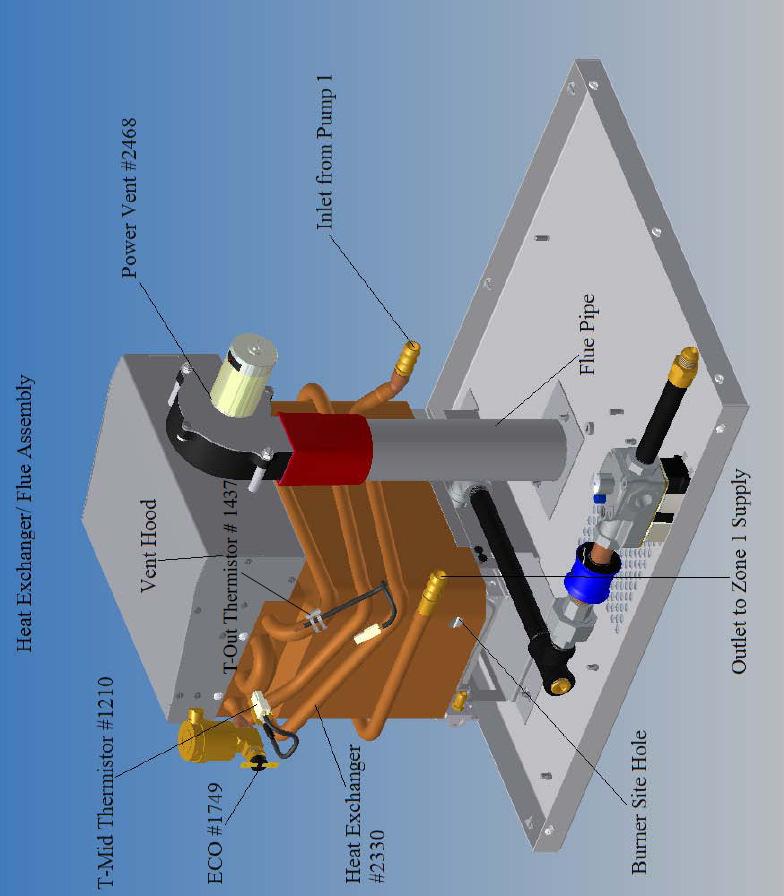
8 TwinTemp Description of Operation and Sequence of Operation Technical Description of Operation- The TwinTemp systems provide quiet space heating utilizing liquid to air blowers or radiant devices, while producing a continuous supply of hot water. Its Variflame gas modulation enables it to use a very small tank and still maintain efficiency without rapid burner cycling. This greatly reduces startup time and standby heat loss. Unlike its diesel counterparts the TwinTemp has an instant on burner and modulates the gas flow on a 4-1 ratio. A copper heat exchanger inside the tank of heated antifreeze in used to indirectly heat the potable water. This method is not only efficient, but will extend the life of the critical heat exchange elements, tank and circulating pumps. Sequence of Operation The power and propane are turned on to the TwinTemp. If the Tank thermostat senses low tank temperature (below 190 F), it will send 12 vdc power to the green control board and Pump 1 (rear) pump. Note- the Junior has one zone pump and the TwinTemp-2 has 2 zone pumps. Anti-freeze starts to circulate from the bottom of the tank, through Pump 1, to the burner heat exchanger, out to Zone 1 blowers and back to tank. Simultaneously, the control board powers the power vent relay which activates the power vent and fluing is proofed by the pressure switch via the ¼ hose. The pressure switch sends 12 VDC to the ignition board (if flue is blocked, burner will not light). The solenoid gas valve is energized and a spark is affected to the igniter probe over burner via the heavy ignition wire. The flame is proofed via the same igniter element and yellow wire. Gas flow is adjusted by the gas modulating valve based on antifreeze temperature. Temperature readings are taken twice per second by the T-Mid Thermistor. As set temperature (about 190 F) is approached, the gas flow is reduced as much as 70% by reducing the voltage to the gas modulating valve until set temperature is achieved and the burner goes off. When a hot water tap is opened, cold water enters the copper tank heat exchanger imbedded in the tank and the heat transfer takes place. The hot water exits the tank coil through a tempering valve that can be set to any temperature between As the tank cools, the burner cycle starts again when the tank thermostat senses the tank is getting cold. If the zone 1 room thermostat senses low room temperature, it sends power to the zone s relay that then powers pump 1, control board and the zone blowers. When the zone 2 (TwinTemp-2 only) thermostat calls for heat the zone 2 relay sends power to the pump 2 and the blowers in zone 2 are activated. The burner will be activated by the tank thermostat as above if the antifreeze temperature falls below set temperature. The blower thermostat will turn off the Zone 1 blowers if tank temperature drops below 160 F. NOTE: The bold orange terms are identified and pictured in the following pages. Rev 6/15/

9 Rev 6/15/

10 Rev 6/15/
11 Rev 6/15/

12 Rev 6/15/

13 Rev 6/15/

14 Rev 6/15/
15 TwinTemp Troubleshooting Guide - Chart 1 Rev 6/15/

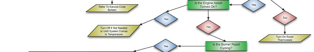
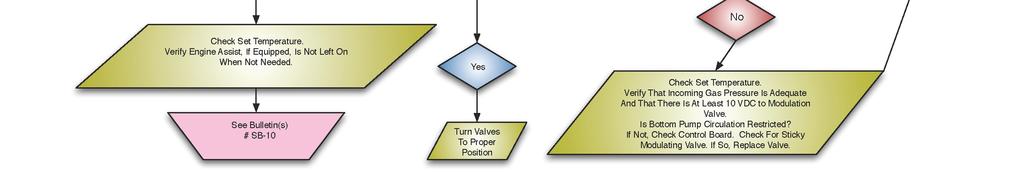
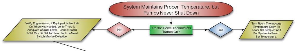

16 TwinTemp Troubleshooting Guide - Chart 2 Rev 6/15/

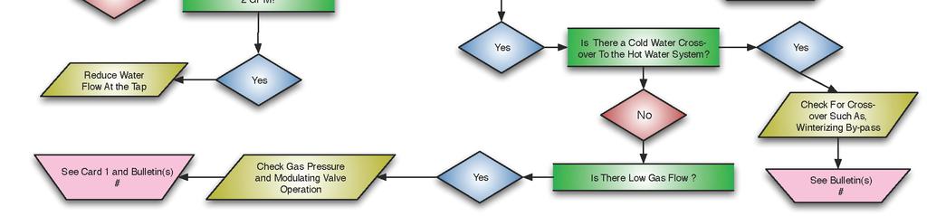
17 TwinTemp Troubleshooting Guide - Chart 3 Rev 6/15/
18 TwinTemp Junior Troubleshooting Guide - Chart 1 Rev 6/15/


19 TwinTemp Junior Troubleshooting Guide - Chart 2 Rev 6/15/
20 TwinTemp Junior Troubleshooting Guide - Chart 3 Rev 6/15/
21 Rev 6/15/
22 Rev 6/15/
23 Rev 6/15/
24 Rev 6/15/
25 Rev 6/15/
26 Rev 6/15/
27 Rev 6/15/
28 Rev 6/15/
29 Rev 6/15/
30 1076- Modulating Gas Valve Connection Thermistor Wiring Harness Connection Power Supply Wiring Harness Connector DSI Wiring Harness Connector Alarm- Alarm connector not used (in this application) ACAL Jumper- Jumper for Auto-Cal JMP 1 Jumper- Board Function Jumper (Do not change!) Orange Test Point- Test point for T Out Thermistor Yellow Test point- Test point for T Mid Thermistor Blue Test Point- Test point for setting temperature Brown Test Point- Test point for Modulating Valve Black Test Point- Test point for ground (common) Rev 6/15/
31 TwinTemp Service Codes SB-7-RC- Lost autocal or not autocal displays alternating green and red flash SB-15, 17- T-Mid or T-Out failure displays steady red and flashing green LED Lock out after 10 ignition attempts displays red and green LED flashing together Note: The TwinTemp will reset or clear codes, with power applied to the control board, every 10 minutes. Hard faults or open circuits will not be erased. Rev 6/15/
32 TwinTemp Service Bulletin Index Model: TwinTemp SB-01 Power Vent Blower Exchange Procedure SB-02 Pressure Switch Adjustment SB-03 Circuit Board Replacement SB-04 Pressure Switch Replacement SB-06 Direct Spark Ignition (DSI) Board Change SB-07 Auto-Calibration SB-08 Modulating Valve Change Procedure SB-09 Heat Exchanger/ Burner Change Out Procedure SB-10 Changing Set Temperature SB-11 Tempering Valve Adjustment and Replacement SB-12 Gas Solenoid Change Procedure SB-14 Igniter Cap Adjustment SB-15 T-mid Thermistor Change Procedure SB-16 T-out Thermistor Change Procedure SB-17 Re-Circulating Pump Change Procedure SB-18 Temperature Switches Replacement SB VAC Heating Element Replacement SB-20 Tank Replacement Procedure (CALL PRECISION TEMP) SB-21 Gas Valve Pressure Check and Adjustment SB-22 Thermistor Reading Procedure SB-23 Removing and Replacing TwinTemp Unit Rev 6/15/
33 Model: TwinTemp SB-I Power Vent Blower Replacement Other service documents required: SB-2 Pressure Switch Adjustment Tools & Supplies Required- 3/8 nut driver 7/16 nut driver Phillips Head Stubby Screw Driver Flat Blade Screwdriver Utility Knife Silicone Sealant 1. Remove front panel and top of unit using Phillips head. 2. Disconnect spade connectors from blower and voltage regulator. 3. Remove spring clamp from pressure switch tube and remove. 4. Using 3/8 nut driver, remove the two lock nuts from the hood studs securing the blower. 5. Using the 7/16 nut driver, loosen clamps holding rubber collar on flue pipe below blower. 6. Remove the old blower, taking care not to lose the aluminum spacers. Rubber collar may have to be slipped down to remove blower. 7. Install new blower by reversing the process. Be sure to install aluminum spacers. The rubber collar may have to be raised up again so flue pipe installs over the blower outlet. 8. Using silicone sealant, seal opening between blower outlet & flue pipe. Models produced after 1/2010 do not require silicone. 9. Re-connect hose to blower barb and test pressure switch operation using SB-2. Rev 6/15/
34 Model: TwinTemp SB-2 Pressure Switch Adjustment Tools & Supplies Required: Flat blade screw driver Stubby Phillips screw driver Allen wrench set 1. Remove access panel with stubby Phillips screw driver. 2. Turn the TwinTemp on. With the blower running, verify if the burner is staying on, cycling rapidly or not at all. 3. If burner is not staying on or cycling, using the flat blade screw driver, turn the adjustment screw on the pressure switch counter-clockwise until the burner lights plus one full turn. 4. Block flue. If burner is staying on even with a blocked flue, turn the screw clockwise until burner goes off with flue blocked plus an additional ½ turn. 5. Block flue and verify burner goes out. If it does not, turn screw clockwise until it does. 6. Unblock flue and verify burner ignites. 7. After adjusting the pressure switch perform several ignitions with the cover on case, to verify proper adjustment of the pressure switch by covering and uncovering the flue pipe. 8. Replace access panels. Ref: TwinTemp Component Illustration Rev 6/15/
35 Model: TwinTemp SB-3 Circuit Board Replacement Other service documents required: SB-7 Auto-Calibration, SB-10 Changing Set Temperature Tools & Supplies Required: Needle-nose pliers 1. Turn off power. Disconnect all electrical connectors at the circuit board. Careful to pull on the connectors, not the wires. 2. Remove the old circuit board. Needle-nose pliers can be used to remove the circuit board nylon standoffs. 3. Install the new board with the LED s located on the lower left side. Reconnect all connectors to the board. CAUTION: there are three two-pin connectors. Be sure that the power supply connector (red and green wire) goes to upper right corner (red connector) and the modulating valve connector (black wire) goes to lower right (blue connector) (see Heater board diagram). The third two- pin connector should already have a connector installed into it. Leave this connector as is. 4. The set temperature should be preset to VDC (195 F). Refer to manual if a further adjustment is needed. See SB Perform auto-calibration per SB-7. Kit Parts List: P/N control board and 9098-O Micro-controller chip (already installed in board) Rev 6/15/
36 Tools & Supplies Required: Stubby Phillips screwdriver 11/32 nut driver Utility knife Model: TwinTemp SB-4 Pressure Switch Replacement 1. Remove access panel with stubby Phillips screw driver. 2. Turn off gas and electric to unit. 3. Disconnect ¼ spade connectors. 4. Disconnect ¼ ID rubber vacuum tube. Cut with utility knife if necessary. 5. Remove lock nuts from studs using 11/32 nut driver. 6. Install new switch, reversing above procedure. 7. Test switch and adjust if necessary using service bulletin # SB After adjusting the pressure switch perform several ignitions with cover on case, to verify proper adjustment of the pressure switch by covering and uncovering the flue pipe. Ref: Pressure switch #2940, TwinTemp Component Illustration, Service bulletin SB-2 Rev 6/15/
37 Model: TwinTemp SB-6 Direct Spark Ignition (DSI) Board Change Tools & Supplies Required: 11/32 socket 1. Turn off power 2. Remove front access panel and disconnect all connectors from the DSI board. Be sure to pull on connectors, not wires. 3. Remove the DSI board and re-attach the wire harness. Be sure to route the ignition wire separate from the other control harnesses. (If a new harness is supplied, use it and discard the old harness. Kit Parts List: #3158 Direct spark ignition board Reference illustrations: Components Illustration Rev 6/15/
38 Tools & Supplies Required: Needle nose pliers Model: TwinTemp Software: 9098K and Later SB-7 Auto Calibration Procedure 1. Turn off power. Let system cool to under 120 before proceeding. Remove access panel. From the heater control board, remove the 2-pin (right) jumper from the terminal marked Acal using pliers or fingers (see view of Heater Control Board). Be sure gas supply is on. 2. Turn power ON. The unit will ignite at the ignition gas flow and fluctuate the gas flow to the burner. Over the next 1 minute the gas flow will change slightly as the computer determines the proper voltage for minimum flow. After the computer completes auto-calibration the burner will automatically shut off. 3. Turn off power. 4. Replace jumper on board. 5. Turn power on to check the unit for normal operation. Figures View of heater control board Rev 6/15/
39 Model: TwinTemp SB-8 Modulating valve replacement Tools required: 13/16 open end wrench 12 adjustable wrench. When performing the following, always back up mating plumbing fitting with a wrench to avoid damage to gas train. Be sure not to allow any pipe dope to get into any components of the gas train. NEVER use pipe dope on a flare fitting. 1. Turn off power to unit. 2. Disconnect the blue & white wire connected to the gas valve. 3. Turn the gas supply to the unit off. 4. Unplug modulating valve wire from the heater control board. 5. Separate the gas union between the burner and modulating gas valve with the adjustable wrench. 6. Remove flare nut from inlet fitting of gas valve with 13/16 wrench. 7. Remove the gas valve assembly and then remove modulating valve from gas valve. 8. Install new modulating valve in reverse order using approved pipe sealant, taking care that sealant does not get into the modulating gas valve. Be sure to observe gas direction arrows when re-assembling. 9. Pressurize gas line. An auto-calibration must be done after replacing the modulating valve. (See bulletin # SB-7) Be sure to check all gas fittings with a leak test solution before energizing. After energizing, check for leaks at the union. Note: It may take several attempts at ignition to purge all of the air out of the refitted gas line. Figures Component illustration, Auto Calibration bulletin #SB-7 Rev 6/15/
40 Model TwinTemp SB-9 Heat Exchanger/ Burner Assembly Replacement Contact PrecisionTemp Service Department or Rev 6/15/
41 Tools & Supplies Required- Small flat blade screwdriver Digital Multimeter Model- TwinTemp SB-10 Changing Set Temperature The temperature on the TwinTemp Junior has been factory set to approximately 195 antifreeze temperature. It is not recommended that you change this setting. Doing so could result in inadequate performance and the pump never shutting down. If it is necessary to change the setting please follow the instructions below. 1. Open access door. Locate the Heater Control Board (see Heater Control Board illustration). The adjustment screw is located on a small blue block at the left side of the board. 2. A small bald screwdriver should be used. To decrease temperature, turn screw counterclockwise. 3. Use a voltmeter, placing the black lead into the black test point and the red leas into the blue test point. Adjust the screw to read 4.40 VDC 4.60 VDC on the voltmeter. This will set the temperature control to the recommended temperature. 4. Now run heater stabilization temperature with all blowers off. There should be no sign of boiling and the pump should shut down when tank reaches proper set temperature. See Heater Control Board illustration Rev 6/15/
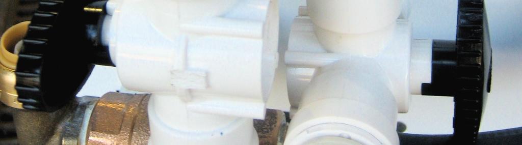
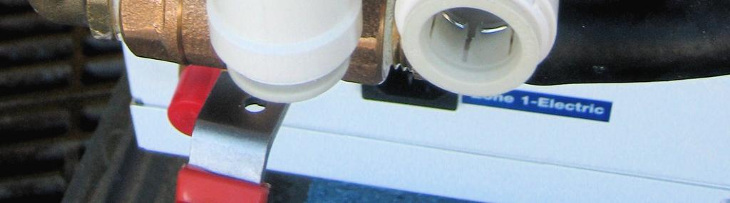
42 Model: TwinTemp SB-11 Tempering Valve Adjustment and Replacement Tools & Supplies Required- Channel Locks Phillips screwdriver The tempering valve is adjusted to about 120 at the factory. It is not advisable to set it to a higher temperature, since scalding may result. If adjustment is needed, proceed as followed. 1. Turn on TwinTemp Junior until tank is up to operating temperature. 2. Remove front cover & locate tempering valve (see TwinTemp Junior Components Illustration). 3. To increase hot water output temperature, turn gray knob counter-clockwise. To decrease the temperature turn gray knob clockwise. Adjustments should be made in ¼ turn increments. 4. Turn on hot water and tap and let run for at least 45 seconds to test outlet temperature and re-adjust if necessary. To replace the valve, proceed as follows. Newer models will have quick disconnect fittings replacing nuts and gaskets. 1. Remove front cover. 2. Turn off water pressure, depressurize system and let cool. 3. Using the Channel Locks loosen the three large nuts on the ports of the tempering valve and remove back nuts completely. 4. Slide old tempering valve and gaskets off of the mating flanges. 5. Take care to clean dirt and old gaskets off of the mating flanges. 6. Slide new valve into place, taking care to install in proper orientation (Hot inlet up). 7. Carefully slide new gaskets between the valve housing and mating flanges. 8. Tighten the nuts with the Channel Locks. 9. Turn on water pressure and check for leaks. 10. Adjust temperature as described above. Kits Parts List & References- #3128- Tempering Valve with shark bite fittings F, TwinTemp Components Illustration Rev 6/15/
43 Tools & Supplies Required: Short Phillips screwdriver Small flashlight Model: TwinTemp SB-14 Igniter Adjustment 1. Remove access panel from TwinTemp 2. Turn power off, water off and gas off. 3. Remove ignition cable from bottom of igniter probe. Pull on connector, not the wire. 4. Loosen screw on igniter clamp enough to allow for movement of the probe. 5. Through open in lower heat exchanger view igniter probe position over burner. 6. Manually turn probe to position the tip directly over burner element, allowing for a 1/8 gap. 7. Hold probe in set position and tighten screw to secure it, being sure probe is still directly over burner element and about 1/8 above it. 8. Reinstall Ignition Cable. 9. Turn on power only. When unit tries to ignite, view spark through opening. Verify proper gap and spark during ignition. 10. Reinstall access panel, turn water and gas supply on. Rev 6/15/
44 Model: TwinTemp SB-15 T-mid Thermistor Change Procedure Tools & Supplies Required: 9/16 open end wrench Adjustable wrench 1. Remove old thermistor. CAUTION: Use two wrenches on the hex (9/16 ) of the thermistor and an adjustable wrench on the hex located on the heat exchanger fitting. Failure to do so may seriously damage the heat exchanger. 2. Slide the nut and the new ferrule over end of the thermistor probe with tapered end toward tip. 3. Insert the thermistor tip into the heat exchanger until the heat shrink (black) on the thermistor touches the fitting and tighten the fitting finger-tight. The final tightening should be done using two wrenches as described in step Check the resistance across the thermistor leads. Under room temperature conditions the value should be between OHMS. A further check can be done by comparing the resistance to the other thermistor. If both thermistors have been exposed to the same temperature they should be within +/- 50 OHMS. 5. Wrap the harness together with the other thermistor harness and connect into the yellow thermistor harness that goes back to the control board. Kits Parts List: #3207 T-mid thermistor including ferrule Rev 6/15/
45 Model: TwinTemp SB-16 T-out Thermistor Change Procedure Tools & Supplies Required: Scissors (or other cutting tool) 1. Remove the wire ties, metal tape, and old thermistor. Clean off the old heat sink and be sure copper is wiped clean. Note: some units may have a clip on thermistor that just snaps off the pipe. 2. Place an ample amount of heat sink compound on the pipe wire where the thermistor will be located. 3. Place the thermistor into the heat sink with the wire leads pointing down along the tube. 4. Wrap metal tape around the tube and thermistor (or snap on new thermistor). 5. One wire tie goes around the wires as a strain relief. The other goes near the thermistor (about ¼ away from the head) to hold the thermistor against the tube. Caution: 1) Do not place the tie wrap over the thermistor as may crack the thermistor, and 2) do not over tighten the wire ties. 6. Wrap the thermistor harnesses together and connect into the thermistor harness that goes back to the control board. 7. Perform test of the unit. Kits Parts List: #1437 T-out thermistor Rev 6/15/
46 Model: TwinTemp SB-17- Re-circulating Pump Tools & Supplies Required: Phillips screwdriver Side cutters Ratchet with 3/8th wrench Needle nose vise grips 1. Turn off power and gas and let system cool. 2. Zone 2 pump must be removed to access Zone 1 pump. 3. Depressurize tank by carefully opening the fill plug located on the tank under the top of the access panel. 4. Remove front access panel. Zone #2 pump is located closest to the access door. 5. Drain and save fluid from the system. 6. Disconnect connectors from the pump. Be sure to pull on the connectors and not the wires. 7. Clamp off black hose pump with vise grips. Using the side cutters cut the banded clamps off the hose. Take clamp off black pump hoses using the vise grips. 8. Carefully cut banded clamps on the suction and discharge side of the pump. 9. Using a 3/8th quarter inch drive socket remove the 2 nuts from pump bracket. 10. Remove connectors from pump. Be sure to pull on connectors, not the wires. Carefully remove pump from unit. 11. Reverse procedure to re-install using new hose clamps. 12. To remove Zone 1 pump the Zone 2 pump must be removed first. 13. Using the same procedure used in removing the Zone 2 pump, disconnect and remove the Zone 1 pump. 14. Reverse procedure to re-install. 15. Fill system with fluid. Tu 16. Check for fluid leaks and top off fluid. 17. Turn gas on and run the TwinTemp-2/ Junior for minutes to bleed any trapped air pockets in plumbing, re-check for leaks and top off fluid. 18. Top off fluid with a 50/50 mix of Rhogard Propylene Glycol Boiler antifreeze Note: If a banging sound is heard during ignition, an air pocket is trapped in the heat exchanger. Turn off gas and continue to purge air from the system for an additional minutes. Rev 6/15/
47 Tools & Supplies Required: 1-1/2 deep well socket 11/32 socket Model: TwinTemp SB-19 Electric Heating Element 1. Disconnect all power from TwinTemp, de-pressurize tank and drain antifreeze. 2. Remove access cover from the TwinTemp unit. 3. Remove 11/32 nuts from the heating element cover. 4. Slip cover to left. 5. Disconnect wires from heating element. 6. Using a 1 and 1/2 deep socket turn counter-clockwise and remove element. 7. Reverse procedure for installation being sure to install new gasket. 8. Top of fluid level in tank and purge all air from the system. Kits Part List: # 2248 Electric Heating Element, 50/50 propylene glycol boiler antifreeze / water mix Rev 6/15/
48 Model: TwinTemp SB-21 Gas Pressure Check and Adjustment Tools & Supplies Required: Small flat blade screwdriver 3/16 hex key, Manometer 1/8 NPT fitting from manometer hose Dynamic gas supply pressure (to TwinTemp regulator)= 11.0 WCI 1. Turn off power to TwinTemp unit. 2. To test manifold gas pressure, use a 5/16 allen wrench or 3/8 open end wrench to remove test port plug. Install tube from manometer using a 3/8 npt onto test port. Be sure it is a tight fit and doesn t leak. 3. Turn power on. The TwinTemp unit will start the ignition sequence and the burners will ignite. 4. Gas pressure should read between 1.0 WCI (at low burn) to 9.2 WCI (at max burn). 5. Placing a magnet between the mod valve coil and the combination gas valve will fully open the modulating valve. Maximum gas pressure should read between 9 WCI and 9.5 WCI. 6. When testing is completed turn off power and close valve at the test port. To test gas pressure at the Maxi Control valve: 1. Turn off power to TwinTemp unit 2. To test gas pressure at the Maxi Control valve, remove the hex plug from the valve. Insert a 1/8 NPT fitting in place of the plug and connect hose from the manometer. 3. Turn on power to TwinTemp unit. 4. The TwinTemp unit will start the ignition sequence and the burners will ignite. 5. Gas pressure should read approximately 11 WCI with the burner on. 6. If an adjustment is needed to reach 11 WCI remove the pan head screw from the Maxi Control and turn the nylon screw which is exposed. Turn the nylon screw clockwise to increase and counter-clockwise to reduce pressure, not to exceed 11 WCI. 7. When testing is complete turn off power and reinstall plug and screw in Maxi Control Valve. NOTE: if maximum pressure cannot be achieved by adjusting the Maxi Control valve, check the main gas regulator at the propane supply and adjust if necessary to achieve the 11 WCI. Rev 6/15/
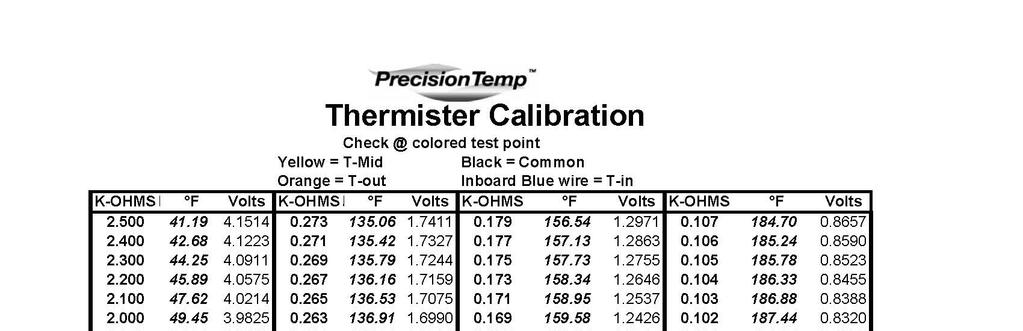
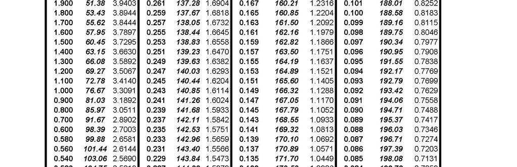
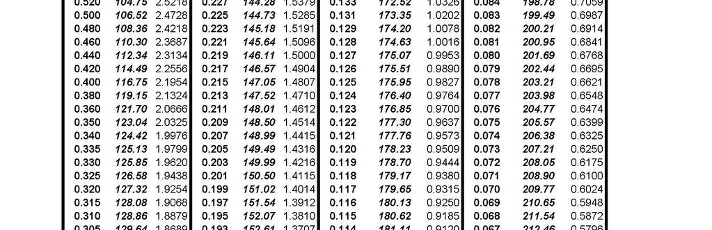
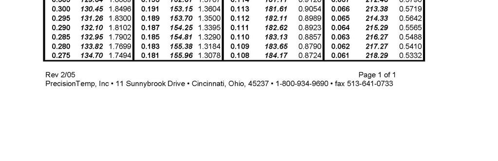
49 Model: TwinTemp SB-22 Thermistor Reading Procedure The precise temperature of the coolant in the heat exchanger can be determined by reading thermistor DC voltages at the colored test points on the green control board (SEE ELECTRONIC CONTROL BOARD) with a multi-meter and referring to the Thermistor Calibration table. The black multi-meter probe should go into the black test point and the red probe should go into the following test points: Orange Test Point = Outlet temperature (T-out) Yellow Test Point = Mid-HX temperature (T-mid) Power must be on to the TwinTemp to take readings, but the burner does not necessarily have to be activated. Refer to the DC voltage reading in the volts column on the Thermistor Calibration chart. The corresponding temperature is the column to the left of the volt reading. NOTE: Voltage on the T-Mid thermistor (Yellow test point), should be between VDC when burner goes off and between VDC when burner re-ignites. If the voltage plunges much below the off reading when the burner goes off, check the antifreeze level and the zone 1 pump performance or for any obstruction in the zone 1 anti-freeze system. There is inadequate circulation through the burner heat exchanger. If the re-ignite voltage is much higher that the above voltages, check that T-set voltage on the blue test point is between volts. Rev 6/15/
50 Model: TwinTemp SB-23 Removing & Replacing TwinTemp Junior Unit 1. Turn off all power to TwinTemp Junior and disconnect all electrical connections. 2. Turn off water and gas supply. 3. Drain TwinTemp J unit by disconnecting heating supply plumbing connection and turn on 12 VDC power to pump anti-freeze from tank. 4. Disconnect remaining gas, water and fluid lines. 5. Unscrew the exhaust pipe from under the coach. 6. Remove the 4 mounting nuts and washers from the under coach floor. 7. Carefully remove the TwinTemp Junior unit from the coach. 8. Reverse procedure to install TwinTemp Junior Unit. 9. Top off all fluids. 10. Run system to purge air from all lines and recheck fluid until tank is full. 11. Check anti-freeze level and top off if needed. 12. Start up unit and test using the Start-up and Testing Document. Rev 6/15/
51 Rev 6/15/
52 Part # TwinTemp Part List 8/ Spark Ignition Probe 1073 TwinTemp Gas Solenoid LPG /8" LPG Modulating Gas Valve Assy, 1103 Modulating Valve Coil 1412 Wire, Ignition Cable 1437 T-out Thermister (red wires) 1495 Thermistor Wiring Harness 1749 Bimetal ECO 1/8" 220 F +/- 7 auto reset at 170 F 1829 DSI Wiring Harness 2028 Relay, Omron 2123 Tempering valve w/flanges (all models prior to 3/2007) 2162 Electric Elements 200 deg. tank Thermostat (prior to 11/2007) 2248 Electric Heating Element 2451 Power Vent Blower Motor Assy Amp Circuit Breaker 2558 Room Thermostat / wall mount deg. Bimetal tank Thermostat (Obsolete 6/2009 use p/n 3264 ) 2582 Air bleeder vent 2735 Magnetic Drive Pump Brushless 12 VDC 2737 Summer/Winter ball valve /2 Heater Hose Elbow 2751 On/Off switch TT2 & Jr Low profile secondary liquid to air heat exchangers w/fans 2844 Tank assembly for the Twin Temp-2 Dual Zone 2828 Tank Assembly for the Twin Temp Jr. Single Zone 2932 Heat Exchanger (Specify 'G', 'F' or 'C' model) 2940 Pressure Switch,.1 WCI Vacuum (normally open, 12v DC) 2942 Complete wire harness for TT deg. Switch, High Limit, Manual Reset (used w/electric element) 2952 Electric Elements hi limit ECO deg. (after 11/2007) vDC blower voltage regulator 3012 Complete wire harness for TT-Junior 3017 Burner Assembly psi Radiator Cap 3121 Liquid to air heat exchanger with one fan 3122 Liquid to air heat exchanger with one fan and thermostat 3128 Tempering Valve ( shark bite fittings ) 3158 DSI Board 3166 DSI adapter bracket used with P/N Assembly T-Mid (Yellow wire) 3227 Pressure Relief Valve 3/4 npt 30 psi deg. Bimetal tank Thermostat deg. Tank Thermostat Retrofit Kit (replaces P/N 2559) 9098 Micro processor software chip Control Board & Microprocessor for TwinTemp Rev 6/15/
53 The TwinTemp systems are certified as a power vented automatic instantaneous water heater/ furnace, designed to be installed in recreational vehicles or mobile homes. This appliance must be installed in accordance with local codes or in the absence of local codes the following applies: Manufactured Home: Title 23 CFR, Part 3280 Recreational Vehicle: ANSI A119.2/ NFPA 501-C-1987 Every TwinTemp is inspected and tested before it leaves the factory. In order for this unit to operate safely and effectively, all installation instructions must be followed. Failure to comply with all installation and operating instructions will void the warranty. PrecisionTemp, Inc. will not be responsible for anything that is a result of non-compliance. FOR YOUR SAFETY WHAT TO DO IF YOU SMELL GAS Extinguish any open flame. Shut off the gas supply at the container or source. Do not touch any electrical switch or use any phone or radio in the vehicle. Do not start the vehicles engine or electrical generator. Contact the nearest gas supplies or qualified service technician for repairs. If you cannot reach a gas supplier or qualified service technician, contact the nearest fire department. Do no turn on the gas supply until the leak(s) has been repaired. FOR YOUR SAFETY DO NOT STORE OR USE GASOLINE OR OTHER FLAMMABLE VAPORS AND LIQUIDS IN THE VICINITY OF THIS OR ANY OTHER APPLIANCE. WARNING! Improper installation, adjustment, alteration, service or maintenance can cause property damage, personal injury or loss of life. Refer to the installation instructions and/ or operating instructions provided with this appliance. A qualified installation service agency or the gas supplier must perform installation and service. Keep this book with the TwinTemp at all times. It contains instructions regarding installation, operation and maintenance of your TwinTemp. If you need further information, contact your dealer, your nearest service center or PrecisionTemp Inc. Rev 6/15/
54 Installation Instructions Please read these instructions thoroughly before starting your installation Note: These instructions apply to both models. The TwinTemp-2 is a dual zone heating unit whereas the Junior is a single zone. Both also provide continuous hot water. Installation is identical except for the additional zone, optional engine assist and HotTap on the TwinTemp-2. The TwinTemp is designed to be installed in a ventilated compartment of the vehicle such as a lower luggage compartment or basement and vented through the bottom of that compartment to the outside. The heater must not be mounted in the living area of the vehicle or in a way that receives its combustion air from the living are or flues into the living area of the vehicle. Doing so will void the warranty and cause the heater to malfunction and could cause damage, injury or death. Please read these instructions before making any modification to the construction of your RV. Installation Overview The installation of the TwinTemp is done in three steps: Installation of main heating unit and exhaust system Installation of blower heating units and thermostats Routing wiring and high temperature tubing from main heating unit to blowers Installation of main heating unit and expansion tank When selecting an installation location, please note the following installation requirements: Surface should be able to support at least 100 pounds The front panel of the heater should be accessible for inspections or servicing The vent must be able to be installed through the floor without interference with frame members or other equipment The compartment where the heater is installed must not be air tight from the outside. There should be at least 12 square inches of fresh air available from the outside, NOT FROM THE LVING AREA OF THE VEHICLE. Caution: the combustion air cannot be supplied from any compartment which may contain combustible gases (i.e. battery gases, gasoline fumes, propane fumes, etc.) Water, gas and electric line should be able to run to the installation. Installation must be done to allow at least 10 access to the front and at least 8 access above the unit. There must be access to all plumbing connections on the right side of the heater if they are not made prior to securing the installation into place. There should be at least 1 clearance in the back. At least 8 of top clearance in recommended to facilitate startup. It is recommended to install the heater as close to the gas supply as practical to minimize the length of the gas line. Rev 6/15/
55 Rev 6/15/
56 Note the locations of the flue cut-out and mounting holes. Be sure they will not interfere with any framing members, wiring or equipment under the coach. Be sure to observe proper clearances around the unit. Drill the four 3/8 th mounting holes. Next cut the 2.25 minimum hole for the flue and the 4: minimum hole for the combustion air. Be sure they are located where they cannot be covered or blocked. NOTE: If the TwinTemp cannot be mounted with sufficient access to the connection side of the unit to make connections after installation, the se connections must be made prior to mounting the unit. See sections regarding Plumbing Hook-ups, Wiring Hook-ups and Gas Line Hook-up. Screw the short end of the supplied vibration absorbing mounting studs into the bottom of TwinTemp. These studs are used to secure the TwinTemp to a floor 1 thick or less. (Note: See below if the floor is more that 1 thick.) If the installation is located in a position which allows access to all hookups after installation, the TwinTemp can now be installed and secured. Lift the TwinTemp into position taking care not to damage the flue transition pipe, protruding from the bottom. Align the flue transition pipe with the flue cutout and all of the mounting studs with the 3/8 mounting holes. Drop the unit into place and secure from below with the flat washers and lock nuts. Following the instructions on the package, install the expansion tank in the same compartment. Attach and clamp the clear tube to the bottom barb on the tank and the barb fitting to the radiator cap. If the floor is more than 1 thick the TwinTemp must be secured with the proper length ¼ -20 bolts, but the vibration absorbing pads must still be used under the unit. Using a hack saw, cut off the treaded studs from the vibration absorbing pads and place pads on the floor near the mount holes prior to placing the unit. Set the unit in place on the vibration absorbing pads, align with the mounting holes and run the bolts from underneath to secure into place. Exhaust Pipe Installation Rev 6/15/
57 The exhaust pipe assembly is supplied in two parts. They are a 2 aluminized steel elbow and a 2 X 18 aluminized steel pipe. After the TwinTemp unit is secured into place the exhaust is installed as follows: Fit the 18 long pipe into the 2 elbow and push the flare side of the elbow up onto the flue tailpiece of the TwinTemp. Locate the pipe out from under the coach while positioning it so that it point about 30 to the rear of the coach. Allowing for about 2 to protrude from under the coach, mark the length, remove and cut to size. Clamp or screw the cut pipe to the elbow and re-position and install to the TwinTemp flue tailpiece. Screw or clamp assembly into place and use a proper exhaust bracket to support the bottom o the coach. A chrome tailpiece can now be installed. NOTE: The above procedure is a typical exhaust installation. If the coach floor is more than 1 inch thick or the tail pipe needs to be longer than 18, contact PrecisionTemp for additional components and information. Interior Heat Exchanger (Blower) and Room Thermostat Mounting Locations Up to four blowers per zone, or a total of eight blowers, can be installed in the TwinTemp-2 system. Up to six blowers can be installed in the TwinTemp Junior system. In a two zone system, the living and kitchen areas are general put on one zone and the bedroom and bath area on the other zone. Each zone is controlled by its own room thermostat. The mounting locations for the thermostats should be selected carefully to ensure even heat distribution throughout each heating zone. Do not mount the thermostat where it can be affected by drafts, dead spots behind doors, radiant heat from the sun, appliances or unheated areas such as an outside wall behind thermostat. Locate the heat exchangers so that even heat distribution will be felt throughout the interior. For slideouts, it is recommended to place blower(s) on the opposite side of the coach, pointing towards the slideout. Sufficient return air must be supplied to each interior blower. (See Illustration 2) Mounting blowers without sufficient ventilation will severely reduce their overall heating performance. In order to provide sufficient ventilation, the return air registers must be the same size or larger that the outlet registers. Return air must be supplied from the interior heating zones. Allow for access to all heat exchangers for tubing hook-up and for potential servicing and cleaning. To mount the blowers once all permanent mounting locations have been selected, cut out the opening for each outlet air and return air register and screw down each heat exchanger permanently into place. Cut an opening for each heat exchanger and cold air return. Mount each heat exchanger permanently into place. Install the hot air outlet and cold air returns. There must be complete access to the heat exchangers until the plumbing and electrical hook-ups have been made. Illustration 2 Rev 6/15/

58 Mounting locations for the water, gray and black tank heat exchanger A tank blower should be strategically placed in the domestic water plumbing area to prevent freezing of the plumbing lines and storage tanks. Position the tank heater in the storage tank/ plumbing bay area so even heat distribution will be achieved. NOTE: The optional heat exchanger with the built-in thermostat should be used. This blower should be installed in zone one loop. For best heating results, place the exchanger as close to the floor of the plumbing bay as possible (heat will naturally rise). Sufficient ventilation (cold air return) must be supplied. Return air should be supplied from the same compartment. Connecting Gas Supply The gas line should be of approved type and size with a 3/8 female flare nut. If the gas line is very long or has numerous bends, it should not be less than 3/8 ID or performance of the TwinTemp will suffer. The maximum inlet gas pressure must not exceed 13 water column inches and no less than 10 WCI. This gas line should be one uninterrupted line from the LPG tank regulator with no tees or connections within the coach. Some standards may require a manual gas shut of valve in the gas line external to the TwinTemp. The TwinTemp must be isolated from the gas supply system during any pressure testing of that system at test pressures equal to it or in excess of ½ PSIG. The flare nut on the gas line Illustration 3 should be hand connected to the flare connection on the TwinTemp to assure it s not cross-threaded. No pipe dope should be used on this flare connection. Tighten with a wrench. This connection should be tested for leaks prior to start up, using soapy water or liquid leak test solution. Do not use a flame to test for leaks. Wiring The TwinTemp is pre-wired internally with a 12 pin connector for all of the 12 VDC hookups (see Illustration 4). A mating pig tail is supplied to make all field connections. Observe the illustration color codes, the wring sizes and procedure described below. The 12 VDC TwinTemp power switch should remain OFF during installation. Note: Illustration 4 shows the TwinTemp-2 connector. The Zone 2 terminals are not used for the Junior. All connections should be secure and not in a wet location. Rev 6/15/
59 12 Volt DC Power Hook-up This is the main power harness that should be switched at a panel inside the coach on a 15 amp circuit. The wire must not be smaller than 12 gauge. Red is positive (+) and black (or green) is negative (-). Under-sizing this wire will result in the TwinTemp malfunctioning. Zone 1 Thermostat and Blower Harness Run 18 gauge wires to the Zone 1 room thermostat, observing the wire colors in the illustration to assure continuity of operation. 18 gauge minimum wires should be wired parallel to each blower in the Zone 1 circuit. The black wire is negative (-) and should be connected to the black wire on the blowers and the colored wire is positive and connected to the red wire on the blowers. Again, observe all wire colors in the illustration. Zone 2 Thermostat and Blower Harness (TwinTemp-2 only) As in Zone 1, run 18 gauge wires, observing wiring colors of the illustration and be sure both thermostats are turned to their lowest setting during installation. Observe polarity of thermostat. 110 Volt AC Electric Elements Cords (Single Element/ Circuit on Junior) These wires are provided with a 15 am SJO plug that is to be plugged into a switched outlet handy box. These should be dedicated 15 amp circuits that are switched at a panel inside the coach. Keep Power off to this circuit at this time. If this circuit in energized prior to filling the system with antifreeze, severe damage will occur. Rev 6/15/
60 Illustration 5 Plumbing The plumbing installation involves three systems: Zone heating system blowers Domestic hot water system HotTap system (optional) It is recommended to use 5/8 OD minimum PEX high temperature tubing and push fitting, similar to what PrecisionTemp can supply. Otherwise, an adapter will be required to make the connections. Zone Heating System Blowers Piping Illustration 6 The heating system consists of two separately controlled zones with up to four blowers in each zone (TwinTemp-2). The Junior can service up to six blowers. The TwinTemp has a supply line and a return line connection for each zone (see Illustration 6). It is suggested to use the red PEX line for Zone 1 and the blue PEX pipe for Zone 2 to avoid confusion during hookups. Prior to running the PEX pipe, it is advisable to connect all PEX push fittings to the blowers and the TwinTemp water/ anti-freeze connections. Use a high quality Teflon tape on these fittings when making the connections. Take care not to let the Teflon tape get into the system. The Zone 1 loop should be used for the longest loop with the most blowers in it, generally the living room/ kitchen loop. Install all PEX pipe and mark with labels at both ends. Arrows should indicate the supply and return lines. Minimize extreme bends and any extreme rises in height should be avoided. Where possible use flow bender clamp rather than elbow fittings the reduce restriction. PrecisionTemp can supply the flow benders. Be sure the secure all PEX where necessary and apply protective shielding in areas where chafing may occur. As shown in Illustration 6, the 3 way by-pass valve and tee fitting has been installed between the supply and return fittings in Zone 1. This is to prevent the heated anti-freeze from circulating to the blower units in warm weather, when space heat is not required. Connect to the Zone 1 supply line from the TwinTemp to the by-pass tee and then continue it to the closest blower unit. Be sure the end of the PEX is cut perfectly square and push it into the push fitting until it bottoms out. Then pull gently on the PEX tube to assure it is tight into the fitting to avoid leaks. Continue this process until all blowers in the Zone 1 loop have been plumbed (up to four blowers). Rev 6/15/
61 From the top outlet fitting of the final blower in the Zone 1 loop, return the red PEX line to the 3 way by-pass valve and continue back to the TwinTemp Zone 1 in (return) fitting of the TwinTemp. As above, all PEX tubing should be tightly secured to all of the push fitting on the blowers and TwinTemp. (The junior can accommodate up to six blowers on its single zone.) Repeat the above process for the Zone 2 loop using blue PEX piping. Domestic Hot Water Piping Although the TwinTemp is capable of delivering continuous hot water on demand, the plumbing system for the domestic hot water is plumbed exactly as it would be with basic recreational vehicle hot water systems. (see Illustration 6). The pressure cold water supply is connected to the cold fitting on the TwinTemp and the hot water line to the fixtures is connected to the hot fitting. As when running the heating system tubing, be sure to secure the push fitting to the TwinTemp using teflon and cut the PEX tubing square and bottom it out into the push fittings. If the coach is equipped with water pipes other than 5/8 OD PEX tubing, adapters should be used to make the connections to the ½ NPT connections on the TwinTemp. See Illustration 6 Winterizing drawing to incorporate the winterizing valve set into fresh water system (what do I do here????) this will assure a convenient way to drain the fresh water system and prevent freezing of the TwinTemp potable water circuit during freezing conditions. Severe damage can occur if this procedure if not followed. HotTap Piping (TwinTemp-2 Option) The HotTap is a dedicated high temperature hot water tap for food and drink preparation. It can dispense water as high as 190 F and must not be installed when or where there is a risk of scalding. The suggested location is on the kitchen sink countertop near the regular water tap. A clearly visible warning sticker (supplied with the HotTap) should be placed near the HotTap. To install the spigot, follow the instructions packed with your HotTap. The piping to the HotTap must be ¼ soft copper tubing. The tubing should be routed from the TwinTemp compartment to under the sink area where the HotTap is installed. The copper tubing should be routed from the HotTap and the TwinTemp by the ¼ compression fittings supplied. Filling Heating System with Anti-Freeze Before turning on the power to the TwinTemp system, it must be completely filled with boiler antifreeze/ water mixture and completely purged of all air. A 50/50 mixture of water and a high temperature boiler antifreeze propylene glycol with inhibitors must be used. PrecisionTemp can supply this nontoxic boiler anti-freeze or recommend approved suppliers. Never use automotive or other toxic / non toxic anti-freeze. Remove the small access panel on the top of the TwinTemp using a Phillips screw driver. Rev 6/15/
62 Fill system as follows: Remove the radiator tank fill cap from the top of the tank (see Illustration 8). Loosen the small cap of the brass air purging device on top of the heat exchanger. Using a funnel, fill the tank with 50/50 anti-freeze/ water mix. This should be about 2.5 gallons. The Summer bypass valve should be in the Winter position as shown in Illustration 8 (still right???) Turn on propane supply and cycle the 12 volt power switch in 5 second intervals until the burner lights. This will purge the air from the gas line. Set the Zone 1 room thermostat to its highest setting. The Zone 1 pump will circulate the hot anti-freeze through the blower circuit and the anti-freeze level in the tank will drop. Note: Blowers will not come on until tank anti-freeze heats to 160 F. Top of the tank with anti-freeze solution until the level stops dropping. Turn on the Zone 2 thermostat (TwinTemp-2 only) to activate the Zone 2 pump and continue to top off the tank as the fluid level drops. After all blowers come on, level fluid will drop some more. Top off until tank is full. (cont.). Carefully replace the fill cap. Allow both pumps to run for about 15 minutes. Now turn off and check the fluid level and top it off if necessary. Close small cap on Brass air purging device. Check all fittings in heating system and correct if necessary. Note: As unit heats up the anti-freeze will expand into the expansion tank. After all expansion has taken place, be sure expansion tank is filled to full line. When the unit is shut off and cools down the fluid level in the expansion tank will lower. When cold, be sure to fill above the Add line. If expansion tank is ever empty, check the fluid level in the TwinTemp tank and top off if necessary. NEVER remove the tank cap when it is hot. (manual continues on next page) Rev 6/15/


63 Rev 6/15/
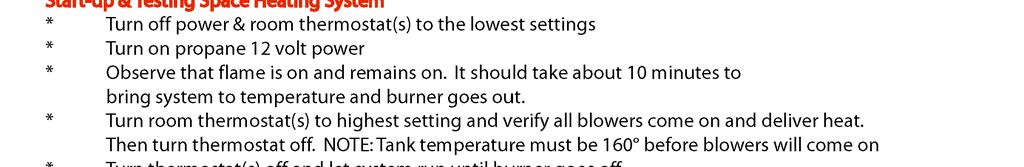
64 Sequence of Operation Before using the TwinTemp for the first time, it is important to know the proper sequence of operation to ensure understand of its operation. Sequence of Operation is as follows: The 12 VDC power switch on the TwinTemp is turned on. Tank thermostat inside turns on Pump 1 and the burner ignites automatically. Anti-freeze circulates from burner to Zone 1 blowers and back to the tank as it heats. Burner remains in high fire until set temperature is approached and gas is modulated to a low burn until set temperature is attained. Burner and pump shut down when set temperature is attained. This takes about 5-15 minutes depending on ambient temperature. TwinTemp is now in standby mode until a room thermostat is activated or hot water is called for. If Room Heat is Needed Set Zone 1 or Zone 2 (TwinTemp only) thermostat to desired temperature. The corresponding pump and blowers will activate and within seconds heat is delivered from blowers. When tank temperature is below set point the burner will re-light and maintain proper tank temperature. When room reaches set temperature, the pump and blowers for that zone will go off. If thank temperature is below set temperature, pump 1 and the burner will stay on until tank reaches set temperature. NOTE: the blower will not activate if the tank temperature is below or drops below 160 F. This assures that the how water function takes priority under heavy usage conditions. Blowers will resume operation when tank temperature goes over 160 F. If Hot Water is Needed Once the tank reaches set temperature (5-15 minutes after system is turned on), continuous hot water is delivered when any tap is opened. Delivery temperature is determined by the setting of tempering valve (Adjustable F). (See Illustration 8) Warning: this valve is factory set at about 120 F. adjusting temperature any higher could result in severe injury due to scalding. Tank thermostat turns pump 1 and burner on automatically when tank temperature starts to drop. Antifreeze circulates from burner and back to tank as it heats. Burner remains in high fire and gas modulates burner to low burn until set temperature is attained. When set temperature is reached, burner and pump shit down and system returns to stand-by mode. To Operate the TwinTemp: Hot Water Pressurize the water system by turning on pump or city water pressure. Purge all air from system by tunring on taps until there is a steady stream of water. Turn off taps. Check for leaks. Turn on the propane supply at tank and the manual gas valve if installed in system. Turn on the 12 VDC power supply and switch on TwinTemp. If this is the first the system has been used, power may have to cycled several times in 5 second intervals until air is purged from the gas line. Using sight hole, verify that burner is on. It will take about 5-15 minutes for the system to heat up. Turn on any hot water tap. Continuous hot water will be delivered in the time it takes to get from the TwinTemp to the tap. Hot water temperature can be changed by adjusting the mixing valve. (see Illustration 8) Rev 6/15/
65 Hot Tap (if equipped) Follow procedures 1-5 above. Depress lever on HotTap dispenser until hot water is dispensed. WARNING: WATER IS EXTREMELY HOT AND CAN CAUSE SERIOUS INJURY! Put container under dispenser, taking care to avoid splashing. Space Heating Follow procedure 3-5 of Hot Water section above. Set the appropriate zone room thermostat to the desired temperature. Blowers in that zone will provide heat within seconds of being activated. When set temperature is attained, blowers will shut down. NOTE: the blowers will not activate if the tank temperature is below 160 F. This assures that the hot water function takes priority under heavy usage conditions. WARNING: Always turn off the 12-volt power supply to the heater during any fueling operations. Operating the TwinTemp or any other ignition source during fueling could cause a fire or explosion, which could result in serious injury or death. NOTE: Should overheating occur or the gas supply fails to shut off, turn off gas valve at the supply tank. Immediately call a qualified service technician. Do not use this appliance if any part has been under water. Immediately contact a qualified service technician to inspect the appliance and replace any part of the control system and any gas control which has been under water. NOTE: When using an on/off button on a shower head or and outside was down box, always turn off the hot and cold water valves when finished. Not doing so will result in cold water bleeding into the hot water system and cold water or alternating warn and cold water will result. The TwinTemp is designed to give a continuous flow of hot water as long as required and maintain the set temperature through all flow rates within the capacity of the heater (88 F temperature rise per GPM). 110 Volt Heating Element The TwinTemp-2 is equipped with two 110 VAC electric heating elements and the junior with one element. These provide limited amounts of hot water or space heating, such as washing hands or dishes. The electric element can be used with our without the propane burner, but for continuous hot water or space heat, the propane burner must be used. To operate, turn the 110 volt switch(es) on in the coach and be sure the power wire is plugged into the handy box(es) in the TwinTemp compartment. For small amounts of hot water only, there is no need to turn the 12 volt power on to the TwinTemp. However, if space heat is required in very cold weather, the 12 volt switch should be turned on. If ther is a higher demand for heat that the 110 volt element(s) can provide, the propane burner will activate automatically. For best operation, turn the 110 volt elements on about 30 minutes before turning 12 volt switch on. This allows the tank to come up to temperature utilizing the electric element before the burner can activate. This will help conserve propane. Rev 6/15/
66 NOTE: Be sure that the anti-freeze level is up to the Fill line on the expansion pack before turning the 110 volt element(s) on. Serious damage can occur to the system if the fluid level is low. Changing Hot Water Temperature Setting The temperature on you TwinTemp has been factory set to approximately 120 F. it is not recommended that you set the temperature any higher. WARNING: Changing this setting could result in dangerously hot temperatures that could result in severe injury. If it is necessary to change the setting it can be done as follows: Open access door on the front of the heater. Locate the tempering valve (see Illustration 8). Turn the adjustment knob counterclockwise to increase temperature or clockwise to decrease temperature. The setting range is between 100 F to 145 F. Summer Operation When the space heating function of the TwinTemp is not needed, the heated anti-freeze should not be circulated to the blowers. To prevent this circulation, the Summer by-pass valve (see Illustration *) should be turned ¼ turn. The Summer position is opposite the position in Illustration 8 (correct?). When heating is again needed, this level should best turned ¼ quarter turn from the Summer position to the same position as is shown in Illustration 8. this adjustment should only be needed twice a year for summer/ winter operation. Routine Maintenance All faucet aerators and showerhead screens in the coach should be cleaned regularly. It is recommended that the TwinTemp be inspected by a qualified service technician at least once a year. Particular attention should be paid to the following: Be sure that the air inlet openings and flue area are clear of any debris or obstructions (leaves, bugs, nests, spider webs etc.). Be sure nothing is stored against the unit that would block air or access. Make sure anti-freeze level in tank is full and up to the Fill line on the expansion tank. Top off if necessary with a 50/50 mix of specified boiler anti-freeze and water. Check that heater mounting is still secure to the coach. Tighten if necessary. Visually inspect wiring and hoses. Be sure there is no chafing of the insulation. Drain boiler antifreeze every two years and replace with new. (system holds approximately 6 gallons of a 50/50 boiler antifreeze/water mix) Rev 6/15/

67 NOTE: This winterizing procedure applies to all TwinTemp Models produced from January 2008 to present Rev 6/15/

68 Rev 6/15/
69 NOTE: This winterizing procedure applies to all TwinTemp Models produced from October 2007 to January Rev 6/15/

70 Rev 6/15/
TWINTEMP JR. HYDRONIC SYSTEM 2/2013
 TWINTEMP JR. HYDRONIC SYSTEM 2/2013 TwinTemp Description of Operation and Sequence of Operation Technical Description of Operation The TwinTemp systems provide quiet space heating utilizing liquid to air
PrecisionTemp Shower-Mate
 Shower-Mate Instantaneous Gas Water Heater Installation and Operating Instructions The Shower-Mate is a power vented automatic instantaneous water heater designed to be installed in ventilated marine applications.
RV550 EC, RV550NSP EC & M550 EC
 PrecisionTemp RV550 EC, RV550NSP EC & M550 EC Water Heater Service Manual For information, contact: PrecisionTemp,Inc. 3428 Hauck Suite G Cincinnati, Ohio 45241 Phone: (800)934-9690 Fax: (513)641-0733
Certified to ANSI Z / CSA4.3
 ciapmo-t 11 Sunnybrook Drive Cincinnati, OH. 45237 Certified to ANSI Z21.10.3 / CSA4.3 Phone: 513-641-4446 * 800-934-9690 Fax: 513-641-0733 www.precisiontemp.com LPG GAS ON DEMAND WATER HEATER Model RV-550
TECHNICAL INSTRUCTIONS
 TECHNICAL INSTRUCTIONS 24-Month Maintenance Kit P/N 58025-04 For BMK3.0LN Boilers Description of Document: This TID provides the procedures to perform recommended 24-Month maintenance on the following
JOHN DEERE GATOR HPX/XUV 2 PASSENGER HEATER INSTALLATION INSTRUCTIONS (p/n: 9PH20S30)
") P. 1 of 12 JOHN DEERE GATOR HPX/XUV 2 PASSENGER HEATER INSTALLATION INSTRUCTIONS (p/n: 9PH20S30) Item: Qty: Description: 1 2 1 x 1 x 5/8 Tee Fitting 2 2 Plastic Snap-in Hose Grommet 3 4 1-1/2" Hose Clamps
P. 1 of 12 JOHN DEERE GATOR HPX/XUV 2 PASSENGER HEATER INSTALLATION INSTRUCTIONS (p/n: 9PH20S30) Item: Qty: Description: 1 2 1 x 1 x 5/8 Tee Fitting 2 2 Plastic Snap-in Hose Grommet 3 4 1-1/2" Hose Clamps
TECHNICAL INSTRUCTIONS
 TECHNICAL INSTRUCTIONS 24-Month Maintenance Kit P/N 58025-06 For BMK2.0LN Boilers Description of Document: This TID provides the procedures to perform recommended 24-Month maintenance on the following
TECHNICAL INSTRUCTIONS
 TECHNICAL INSTRUCTIONS Benchmark 3.0LN 24-Month Maintenance Kit# 58015-04 This kit applies to units with an Ignitor and a separate gas injector. For units with an Ignitor-Injector (P/N 58023), see Kit
Installation Instructions. For the 18 Built-In Dishwasher and Front Color Panels
 Installation Instructions For the 18 Built-In Dishwasher and Front Color Panels Printed in USA 154232102 Before You Begin DO NOT INSTALL DISHWASHER UNTIL YOU HAVE READ ALL INSTRUCTIONS. FOR YOUR SAFETY,
HX Field Replacement Kit
 Quantity Kit Part Number Description PE 110 Natural Gas Stainless Steel Condensate Pan PT 110 Natural Gas Polypropylene Condensate Pan Model PE 110 LP Stainless Steel Condensate Pan PT 110 LP Polypropylene
LPG GAS ON DEMAND WATER HEATER. Model RV-550
 LPG GAS ON DEMAND WATER HEATER 11 Sunnybrook Drive Cincinnati, OH. 45237 Phone: 513-641-4446 * 800-934-9690 Fax: 513-641-0733 www.precisiontemp.com Model RV-550 This water heater design has been certified
BUILT-IN DISHWASHER INSTALLATION INSTRUCTIONS
 BUILT-IN DISHWASHER INSTALLATION INSTRUCTIONS PLEASE READ COMPLETE INSTRUCTIONS BEFORE YOU BEGIN LEAVE INSTALLATION INSTRUCTIONS AND USER'S GUIDE WITH OWNER ALL ELECTRIC WIRING AND PLUMBING MUST BE DONE
- 12 VDC. HHE M - 12 VDC.
 R OWNER S MANUAL Model Number HHE-200-09E - 12 VDC. HHE-500-09M - 12 VDC. OWNER S INFORMATION Owner s Name: Address: City: State: Zip Code: CUT HERE AND MAIL IN Telephone: E-mail Address: Motorhome Model:
Revision B Printed Fall Elston Manufacturing HC Heater Owners Manual
 Revision B Printed Fall 2007 Elston Manufacturing HC Heater Owners Manual Table of Contents Important Safety Information... ii 1) Description of Heater... 1 General information about your heater including
Service Manual Model 3163
 Service Manual Model 3163 Contents Important Safety Information.......... 1 Specifications.................. 2 General Information.............. 2 Direct Vent Requirements........... 2 Propane System................
V SERIES HDR GAS RANGES
 SERVICE MANUAL ONE POWERFUL PACKAGE V SERIES HDR GAS RANGES TOPS Open Top Hot Top Griddle Top Work Surface BASES Standard Oven Convection Oven Cabinet Base - NOTICE - This manual is prepared for use by
INSTALLATION GUIDE Dual Fuel Ranges
 INSTALLATION GUIDE Dual Fuel Ranges Contents Wolf Dual Fuel Ranges......................... 3 Safety Instructions............................ 4 Dual Fuel Range Specifications.................. 5 Dual Fuel
12.0 cu.ft., 2 way, 4-door, R.V. refrigerator with ice maker.
 Installation Manual For 1200ACXX models: For 120XAC-IMXX models: 12.0 cu.ft., 2-way, 4-door, R.V. refrigerator. 12.0 cu.ft., 2 way, 4-door, R.V. refrigerator with ice maker. The letter X, in the model
SERVICE MANUAL 400SERIES AHE-400-P01
 SERVICE MANUAL 400SERIES AHE-400-P01 Warning Labels Caution Notes As you read this Information, take particular note of the NOTICE, CAUTION, WARNING and DANGER symbols when they appear. This information
Heat Exchanger Block Replacement Instructions
 Series 1-4 Gas-fired water boiler Heat Exchanger Block Replacement Instructions Ultra-80 S1-4 Heat Exchanger Block Replacement Kit, Part No. 383-500-773 Ultra-105 S1-4 Heat Exchanger Block Replacement
COMMERCIAL 24 VOLT FLUE DAMPER
 COMMERCIAL 24 VOLT FLUE DAMPER SERIES WATER HEATER Gas Water Heaters SERVICE MAUAL Troubleshooting Guide and Instructions for Service (To be performed OL by qualified service providers) Models Covered
Installation Requirements for Models:
 900 & 9100 Series Refrigerators Installation Requirements for Models: 9162 9163 9182 9183 962 963 982 983 WARNING Improper installation, adjustment, alteration, service, or maintenance can cause injury
SAFE DRINKING WATER AND TOXIC ENFORCEMENT ACT
 Installation instructions for your new Spacemaker Laundry WSM2780 Gas Before you begin Read these instructions completely and carefully. IMPORTANT OBSERVE ALL GOVERNING CODES AND ORDINANCES. Note to Installer
Service Handbook COMMERCIAL GAS HIGH EFFICIENCY WATER HEATERS
 Service Handbook COMMERCIAL GAS HIGH EFFICIENCY WATER HEATERS 500 Tennessee Waltz Parkway Ashland City, TN 37015 FOR MODELS: BTH 120 THRU 500 SERIES 200/201 INSTALLATION CONSIDERATIONS - PRE SERVICE CHECKS
GAS RACK OVENS WITH ELECTRONIC OVEN CONTROL
 GAS RACK OVENS WITH ELECTRONIC OVEN CONTROL MODELS DRO2G DRO2GH GAS GAS 701 S. RIDGE AVENUE TROY, OHIO 45374-0001 937-332-3000 www.hobartcorp.com FORM 19202 Rev. D (Dec. 2003) IMPORTANT FOR YOUR SAFETY
GAS COOKTOP INSTALLATION INSTRUCTIONS
 INSTALLATION AND SERVICE MUST BE PERFORMED BY A QUALIFIED INSTALLER. IMPORTANT: SAVE FOR LOCAL ELECTRICAL INSPECTOR'S USE. READ AND SAVE THESE INSTRUCTIONS FOR FUTURE REFERENCE. WARNING If the information
AHE S -12 VDC AHE S - 24 VDC
 Owner s Manual Model Numbers AHE-100-02S -12 VDC AHE-200-02S - 24 VDC OWNER S INFORMATION Owner s Name: Address: City: State: Zip Code: CUT HERE AND MAIL IN Telephone: Coach Model: Coach Date of Purchase:
Service Handbook COMMERCIAL GAS HIGH EFFICIENCY WATER HEATERS
 Service Handbook COMMERCIAL GAS HIGH EFFICIENCY WATER HEATERS 500 Tennessee Waltz Parkway Ashland City, TN 37015 FOR MODELS: BTH 120 THRU 500 SERIES 300/301 INSTALLATION CONSIDERATIONS - PRE SERVICE CHECKS
Installation Manual. For Australian refrigerator models: N304M.3 (93 liter 3-way operation with LP gas, 240 volts AC, or 12 volts DC )
") Installation Manual For Australian refrigerator models: N304M.3 (93 liter 3-way operation with LP gas, 240 volts AC, or 12 volts DC ) N404M.3 (128 liter 3-way operation with LP gas, 240 volts AC, or 12
Installation Manual For Australian refrigerator models: N304M.3 (93 liter 3-way operation with LP gas, 240 volts AC, or 12 volts DC ) N404M.3 (128 liter 3-way operation with LP gas, 240 volts AC, or 12
Water Distiller Service Manual
 Water Distiller Service Manual Water Distiller Service Manual L70478WT 2008 Regal Ware, Inc. Table of Contents RECOMMENDED TOOLS... 2 GENERAL INSPECTION...3 BOILING CHAMBER TROUBLESHOOTING & REPAIRS Description...
Internet Version for Reference Only INDUCED DRAFT COMMERCIAL WATER HEATERS SUPPLEMENT INSTRUCTIONS TO PART #
 INDUCED DRAFT COMMERCIAL WATER HEATERS SUPPLEMENT INSTRUCTIONS TO PART #238-39387-00 THIS INSTRUCTION SUPPLEMENT IS ONLY INTENDED TO GIVE INSTALLATION INSTRUCTIONS AND INFORMATION RELATED TO THE INDUCED
PERFECT FIT IN-DASH HEAT/ COOL/ DEFROST FORD PICKUP
 specializing in AIR CONDITIONING, PARTS AND SYSTEMS for your classic vehicle PERFECT FIT IN-DASH HEAT/ COOL/ DEFROST 1960-66 FORD PICKUP CONTROL & OPERATING INSTRUCTIONS The controls on your new Perfect
INSTALLATION INSTRUCTIONS FOR FREESTANDING DUAL FUEL
 INSTALLATION AND SERVICE MUST BE PERFORMED BY A QUALIFIED INSTALLER. IMPORTANT: SAVE FOR LOCAL ELECTRICAL INSPECTOR'S USE. READ AND SAVE THESE INSTRUCTIONS FOR FUTURE REFERENCE. If the information in this
OWNER S MANUAL Manufactured Home Downflow Gas Furnace: MGD-B Series
 OWNER S MANUAL Manufactured Home Downflow Gas Furnace: MGD-B Series Heat Controller, Inc. 1900 Wellworth Ave. Jackson, MI 49203 (517)787-2100 www.heatcontroller.com Owner s Manual MGD-B SERIES GAS FURNACE
Installation Instructions T 9822 Gas Dryer. en - US, CA. To prevent accidents
 Installation Instructions T 9822 Gas Dryer To prevent accidents en - US, CA and appliance damage read these instructions before installation or use. M.-Nr. 07 431 110 2 WARNING For your safety the information
GAS COOKTOP INSTALLATION INSTRUCTIONS BEFORE YOU BEGIN. IMPORTANT Save these instructions for local electrical inspector s use.
 GAS COOKTOP INSTALLATION INSTRUCTIONS Please read this guide thoroughly before installation. To contact LG Electronics, 24 hours a day, 7 days a week: 1-800-243-0000 (U.S.A.) 1-888-542-2623 (Canada) Or
Product Support Bulletin
 MODEL: SUBJECT: CONVENTIONAL, W/ C7 CAT ENGINE WEBASTO TSL-17 HEATER Body DATE: APRIL 13, 2004 INDEX: 6 PAGE: 1 OF 16 Before you start this procedure, perform Freightliner Service Bulletin #20-7 first.
Columbia Boiler Company
 EMG Series Boilers Available in Natural Gas & Propane Rev 12012 Columbia Boiler Company PO Box 1070 Pottstown, PA 19464 Tel (610) 473-8457 Fax (610) 367-6800 Website www.columbiaboiler.com Email cbcsales@ptd.net
Installation Instructions Built-In Dishwasher
 GE Consumer & Industrial Appliances Installation Instructions Built-In Dishwasher If you have questions, call 800.GE.CARES (800.432.2737) or visit our website at: www.ge.com BEFORE YOU BEGIN Read these
SERVICE MANUAL. Bradford White ElectriFLEX HD (Heavy Duty) Commercial Electric Water Heater CEHD SERIES Immersion Thermostat Models
 Commercial Electric Water Heater CEHD SERIES Immersion Thermostat Models") Bradford White ElectriFLEX HD (Heavy Duty) Commercial Electric Water Heater CEHD SERIES Immersion Thermostat Models SERVICE MANUAL Troubleshooting Guide and Instructions for Service (To be performed ONLY
Bradford White ElectriFLEX HD (Heavy Duty) Commercial Electric Water Heater CEHD SERIES Immersion Thermostat Models SERVICE MANUAL Troubleshooting Guide and Instructions for Service (To be performed ONLY
TECHNICAL SERVICE DEPARTMENT Technical Service Bulletin Ultra Low NOx PowerVent with Honeywell Electronic Control California Only
 Error Code Flash TECHNICAL SERVICE DEPARTMENT Gas Valve Status Flash Code Short flash once every four seconds "Heartbeat", alternates bright/dim One Flash, three second pause Two Flash, three second pause
Rev B, 9/2/2009. Kodiak Chiller Overview
 930-0001 Rev B, 9/2/2009 Kodiak Chiller Overview Presentation Outline Phone: 781-933-7300 Lytron Technical Support Contact Information 3 Introduction 4 Part I: Unpacking 5 Part II: Installation 7 Part
STEAMPRO. Steam Generator Troubleshooting and Service Guide
 STEAMPRO Steam Generator Troubleshooting and Service Guide TABLE OF CONTENTS Page PREFACE... 1 I. STEAMPRO STEAM GENERATOR SYSTEM...2 II. PLUMBING AND ELECTRICAL...3-4 III. SYSTEM OVERVIEW... 5-10 IV.
PERFECT FIT IN-DASH HEAT/ COOL/ DEFROST 1968 CHEVROLET IMPALA
 specializing in AIR CONDITIONING, PARTS AND SYSTEMS for your classic vehicle PERFECT FIT IN-DASH HEAT/ COOL/ DEFROST 1968 CHEVROLET IMPALA CONTROL & OPERATING INSTRUCTIONS The controls on your new Perfect
Installation. Leveling
 Your refrigerator was packed carefully for shipment. Remove and discard shelf packaging and tape. Do not remove the serial plate. Location Do not install refrigerator near oven, radiator or other heat
Installation Instructions
 Installation Instructions For the 18" Built-In Dishwasher Sears, Roebuck and Co. Sears Canada, Inc. Hoffman Estates, IL 60179 U.S.A. Toronto, Ontario, Canada M5B 2B8 154435201 Before You Begin DO NOT INSTALL
TECHNICAL INSTRUCTIONS
 TECHNICAL INSTRUCTIONS 24-Month Maintenance Kit P/N 58015-02 For BMK2.0 (Nozzle Mix) Description of Document: This TID provides the procedures to perform recommended 24-Month maintenance on the following
Installation Instructions for the PITCO Self-Cleaning Burner System
 IMPORTANT FOR FUTURE REFERENCE Please complete this information and retain these instructions for the life of the equipment: Model #: Serial #: Date Upgraded: Technician: Installation Instructions for
No. Of Ignition Trials: No. Of Re-Ignition Attempts. Reset by interrupting power for 5.0 Seconds. Diagnostic Output. Re-Ignition Limit Exceeded
 DS1-Q INSTALLATION INSTRUCTIONS General Description Model DS1-Q is used to replace and eliminate the factory installed slow responding glow-bar igniter, sensor and associated wiring in commercial laundry
INSTALLATION INSTRUCTIONS
 INSTALLATION INSTRUCTIONS Accessory Application Publication No. HEATER KIT P/N 0SE01-HL3-102 (SXS700M2/M4) P/N 0SE01-HL3-103 (SXS700M2D/M4D) SXS700M2/M2D/M4/M4D MII 14607-15172 Issue Date REVISED: June
GPC PASTA PRO INSTALLATION & USER OPERATION MANUAL
 GPC-14/18/20 GPC PASTA PRO INSTALLATION & USER OPERATION MANUAL GPC-18 shown with optional rinse station. NOTICE! After installation of your equipment, immediately contact your local gas supplier to obtain
Electronic Ignition Water Heater
 Electronic Ignition Water Heater TROUBLE SHOOTING GUIDE Effective: 5/26/98 Guides are only intended for use on Atwood products by service technicians who have successfully completed Atwood training. This
HEAT/ COOL/ DEFROST FORD THUNDERBIRD
 specializing in AIR CONDITIONING, PARTS AND SYSTEMS for your classic vehicle PERFECT FIT IN-DASH HEAT/ COOL/ DEFROST 1964-66 FORD THUNDERBIRD CONTROL & OPERATING INSTRUCTIONS The controls on your new Perfect
Q - Series Boiler. Troubleshooting Manual
 Q - Series Boiler Troubleshooting Manual WARNING There are a number of live tests that are required when fault finding this product. Extreme care should be used at all times to avoid contact with energized
3500 SERIES CONVECTION STEAM COOKER PARTS AND SERVICE MANUAL
 3500 SERIES CONVECTION STEAM COOKER PARTS AND SERVICE MANUAL EFFECTIVE JULY 30, 2014 Superseding All Previous Parts Lists. The Company reserves the right to make substitution in the event that items specified
PORTABLE ENGINE HEATER AND EXTERNAL BATTERY CHARGER. Specifications: Benefits: IN: NC:
 ENGINEERING THE UNFAIR ADVANTAGE 61-10003 PORTABLE ENGINE HEATER AND EXTERNAL BATTERY CHARGER Benefits: Increased battery capacity Independent of generator power One of the fastest engine heaters on the
Please read this manual completely before attempting to install, operate or service this equipment.
 Service Manual POWER OVEN OFF COOL DOWN COOK LIGHT OFF OVEN READY TEMPERATURE GAS CONVECTION OVEN TIME GAS SHUTOFF ON OFF MODELS 6/13 THE OVEN E SERIES Please read this manual completely before attempting
INSTALLATION INSTRUCTIONS UNDERCOUNTER DISHWASHERS
 INSTALLATION INSTRUCTIONS UNDERCOUNTER DISHWASHERS VIKING 111 Front Street Greenwood, Mississippi 38930 USA (662) 455-1200 IMPORTANT - PLEASE READ AND FOLLOW Before beginning - please read these instructions
PERFECT FIT SERIES IN-DASH HEAT/ COOL/ DEFROST CHEVROLET CHEVELLE/ EL CAMINO NOTE: INSTRUCTIONS DEPICT CHEVELLE
 specializing in AIR CONDITIONING, PARTS AND SYSTEMS for your classic vehicle PERFECT FIT SERIES IN-DASH HEAT/ COOL/ DEFROST 1964-65 CHEVROLET CHEVELLE/ EL CAMINO NOTE: INSTRUCTIONS DEPICT CHEVELLE CONTROL
Operating instructions
 Operating instructions Gas condensing boiler WARNING: If the information in this manual is not followed exactly, a fire or explosion may result causing property damage, personal injury or loss of life.
INSTALLATION INSTRUCTIONS
 Accessory Application Publication No. INSTALLATION INSTRUCTIONS HEATER KIT P/N 0SE01-HL3-101 SXS700M4/M2 Honda Dealer: Please give a copy of these instructions to your customer. PARTS LIST REPAIR KIT (P/N
Installation Instructions
 GE Consumer & Industrial Appliances Installation Instructions Junction Box Cover Within this user bag, you will find a junction box cover and a #10 hex head screw used to attach the junction box cover
Summer Breeze Heater Service Manual
 Summer Breeze Heater Service Manual RSBH RSBH-SB RSBHP Revision: 1.0 Issued: 12-18-2012 Table of Contents I. Basic Assembly and Operation A. Safety Instructions... 2 B. Grounding Instructions... 3 C.
INSTALLATION INSTRUCTIONS GEO PRIME TANK. (Patent Pending) GPC
 GPC") INSTALLATION INSTRUCTIONS GEO PRIME TANK (Patent Pending) GPC Table of Contents General Description 2 Installation 3 Flushing and Purging 5 Initial Start up 7 Adding or Checking Fluid 8 Replacing a Pump
INSTALLATION INSTRUCTIONS GEO PRIME TANK (Patent Pending) GPC Table of Contents General Description 2 Installation 3 Flushing and Purging 5 Initial Start up 7 Adding or Checking Fluid 8 Replacing a Pump
INSTALLATION INSTRUCTIONS & HOME OWNERS MANUAL AUTOBOOSTER IMPORTANT SAFETY INFORMATION
 INSTALLATION INSTRUCTIONS & HOME OWNERS MANUAL AUTOBOOSTER IMPORTANT SAFETY INFORMATION When installing or using any high voltage electrical appliance, basic safety precautions should always be followed.
Built-In Dishwasher. Installation Instructions. BEFORE YOU BEGIN Read these instructions completely and carefully. IMPORTANT The dishwasher MUST be
 Installation Instructions Built-In Dishwasher If you have questions, call 800.GE.CARES (800.432.2737) or visit our website at: www.ge.com BEFORE YOU BEGIN Read these instructions completely and carefully.
INSTALLATION INSTRUCTIONS John Deere One Series; 1023E, 1025R and 1026R Models A HEATER KIT. Figure 1 (General Layout and Parts I.D.
 A-11978 HEATER KIT Figure 1 (General Layout and Parts I.D.) Read these instructions and identify all components. Please retain these instructions for future reference and parts ordering information. Refer
CONTENTS CONSIDERATIONS. General Plumbing Component Connection ILLUSTRATION. Control System CONFIGURATION. Voltage Verification CONNECTION
 AIR SERIES SYSTEM INSTALLATION MANUAL CONTENTS CONSIDERATIONS General Plumbing Component Connection 2 2 2 ILLUSTRATION Control System 3 CONFIGURATION Voltage Verification 4 CONNECTION Component Connection
INTRODUCTION THIS MANUAL INCLUDES IMPORTANT SAFETY INFORMATION
 INSTALLATION AND OPERATING INSTRUCTIONS FOR THE HARDY Fuel Oil Furnace Models D-140 & D-350 HARDY MANUFACTURING COMPANY, INC. 12345 ROAD 505 PHILADELPHIA, MS 39350 PHONE: (601) 656-5866 FAX: (601) 656-4559
TECHNICAL INSTRUCTIONS
 TECHNICAL INSTRUCTIONS 12-Month Maintenance Procedures These instructions apply to the following BMK boiler models (Standard & Dual Fuel): Benchmark 1.5LN Benchmark 2.0LN Benchmark 3.0LN Benchmark 750
PERFECT FIT IN-DASH HEAT/ COOL/ DEFROST PLYMOUTH BELVEDERE
 PERFECT FIT IN-DASH HEAT/ COOL/ DEFROST 1966-67 PLYMOUTH BELVEDERE CONTROL & OPERATING INSTRUCTIONS The controls on your new Perfect Fit system. Offers complete comfort capabilities in virtually every
Installation Instructions
 Installation Instructions Built-In Dishwasher If you have questions, call 800-GECARES or visit our website at: www.geappliances.com BEFORE YOU BEGIN Read these instructions completely and carefully. IMPORTANT
OVATION SERIES FIRE TABLES ASSEMBLY INSTRUCTIONS
 OVATION SERIES FIRE TABLES ASSEMBLY INSTRUCTIONS CSA Model98900 DRS02403 Installer: Leave these instructions with consumer. Consumer: Keep these instructions for future reference. DANGER If you smell gas:
Installation Instructions
 GE Consumer & Industrial Appliances Installation Instructions Junction Box Cover Within this user bag, you will find a junction box cover and a #10 hex head screw used to attach the junction box cover
SERVICE MANUAL AHE-375-P Aqua-Hot Heating Systems Inc.
 WARNING: If the information in these instructions is not followed exactly, a fire or explosion may result causing property damage, personal injury, or death. Do not store or use gasoline or other flammable
NATURAL GAS CONVERSION KIT
 NATURAL GAS CONVERSION KIT Model # 498425 For use with Char-Broil RED Series Grills Only. FOR OUTDOOR USE ONLY This Natural Gas Conversion Kit can be used ONLY with Dual Fuel grills. WARNING CALIFORNIA
DRAIN WATER TEMPERING INSTALL
 ! WARNING! CAUTION DRAIN WATER TEMPERING KIT - 0601-00-07-86 WARNING! This kit should be installed only by qualified service personnel to reduce the risk of electric shock, serious injury, or fire. A plumbing
prestige Condensing Water Boiler SERVICE TECHNICIAN S TROUBLE SHOOTING GUIDE TSG-SOLO-9/04
 prestige Condensing Water Boiler SERVICE TECHNICIAN S TROUBLE SHOOTING GUIDE 2004-28 TSG-SOLO-9/04 Table of Contents INTRODUCTION Page 1 SERVICING TIPS AND INSTRUCTIONS Page 3 CONTROL MODULE DISPLAY -
INSTALLATION INSTRUCTIONS
 INSTALLATION INSTRUCTIONS BUILT-IN BOTTOM MOUNT REFRIGERATOR/FREEZER DBRTGK72SS-GRILLE KIT (FOR designer SERIES ONLY) VIKING RANGE CORPORATION 111 Front Street Greenwood, Mississippi (MS) 38930 USA (662)
PERFECT FIT SERIES IN-DASH HEAT/ COOL/ DEFROST CHEVROLET NOVA
 specializing in AIR CONDITIONING, PARTS AND SYSTEMS for your classic PERFECT FIT SERIES IN-DASH HEAT/ COOL/ DEFROST 1966-67 CHEVROLET NOVA CONTROL & OPERATING INSTRUCTIONS The controls on your new Perfect
Installation & Operating Guide
 5-036 HOT WATER TANK Installation & Operating Guide Read all instructions thoroughly. Keep this guide for future reference. Proof of purchase is required for Warranty. Staple receipt or proof of purchase
southbend A MIDDLEBY COMPANY INSTALLATION AND OPERATION MANUAL CG214 (E) CG314 (E) CG414 (E) CG220 (E) CG320 (E) CG325 (E) GAS BOILERS MODELS:
 CG314 (E) CG414 (E) CG220 (E) CG320 (E) CG325 (E) GAS BOILERS MODELS:") INSTALLATION AND OPERATION MANUAL GAS BOILERS MODELS: CG214 (E) CG314 (E) CG414 (E) CG220 (E) CG320 (E) CG325 (E) southbend A MIDDLEBY COMPANY 1100 Old Honeycutt Road Fuquay-Varina, NC 27526 (919) 552-9161
INSTALLATION AND OPERATION MANUAL GAS BOILERS MODELS: CG214 (E) CG314 (E) CG414 (E) CG220 (E) CG320 (E) CG325 (E) southbend A MIDDLEBY COMPANY 1100 Old Honeycutt Road Fuquay-Varina, NC 27526 (919) 552-9161
Fire Bowls and Fire Bowl Inserts (Automated Operation) Operating and Maintenance Instructions
 Operating and Maintenance Instructions") Table of Contents Section 1: Gas and Electric Requirements... 1 Section 2: Installation... 2 Section 3: Burner Setup and Adjustment... 8 Burner Adjustment... 9 Section 4: Maintenance... 10 Section 5: Operation...
Table of Contents Section 1: Gas and Electric Requirements... 1 Section 2: Installation... 2 Section 3: Burner Setup and Adjustment... 8 Burner Adjustment... 9 Section 4: Maintenance... 10 Section 5: Operation...
ASSEMBLY INSTRUCTIONS - NXS SERIES. INFRARED RADIANT TUBE HEATER Single and Two Stage Pull Through System (Negative Pressure)
") ASSEMBLY INSTRUCTIONS - NXS SERIES OWNER / INSTALLER: For your safety this manual must be carefully and thoroughly read and understood before installing, operating or servicing this heater. INFRARED RADIANT
ASSEMBLY INSTRUCTIONS - NXS SERIES OWNER / INSTALLER: For your safety this manual must be carefully and thoroughly read and understood before installing, operating or servicing this heater. INFRARED RADIANT
Installation Instructions
 Installation Instructions Gas & Electric Dryer Before beginning installation, carefully read these instructions. This will simplify the installation and ensure the dryer is installed correctly and safely.
KIT NOTICE. These instructions are for replacing the three existing thermostats with a single new solid-state thermostat.
 KIT 06401-004-22-16 5 1 2 NOTICE 3 (3 PLC'S) These instructions are for replacing the three existing thermostats with a single new solid-state thermostat. 4 PREPARATION PARTS INCLUDED 6 1 7 5 8 2 4 (4
INSTALLATION & SERVICE MANUAL
 INSTALLATION & SERVICE MANUAL ELECTRIC WATER HEATER THE WARRANTY ON THIS WATER HEATER IS IN EFFECT ONLY WHEN THE WATER HEATER IS INSTALLED AND OPERATED IN ACCORDANCE WITH LOCAL CODES AND THESE INSTRUCTIONS.
Customer Service...1. Calibration...8. Inspection...9. Lighting Cleaning Features Control Box Digital Timers...
 Table of Contents MIRACLEAN GRIDDLE Customer Service...1 Keating of Chicago Web Site...4 Miraclean Griddle Features...7 Calibration...8 Inspection...9 Installation...10-12 Leveling...10 Gas Pressure...11
100T399-SOLA SUPPLEMENT TO INSTALLATION & OPERATION MANUAL INCLUDED WITH WATER HEATER (SERIAL NUMBERS BEGINNING LK AND LATER)
") 100T399-SOLA SUPPLEMENT TO INSTALLATION & OPERATION MANUAL INCLUDED WITH WATER HEATER (SERIAL NUMBERS BEGINNING LK AND LATER) WARNING If the information in these instructions is not followed exactly, a
100T399-SOLA SUPPLEMENT TO INSTALLATION & OPERATION MANUAL INCLUDED WITH WATER HEATER (SERIAL NUMBERS BEGINNING LK AND LATER) WARNING If the information in these instructions is not followed exactly, a
For use with models: PGM304-1, versions M-B PGM365-1, versions M-E, M-F & M-G
 PGM-1 Cooktops For use with models: PGM304-1, versions M-B PGM365-1, versions M-E, M-F & M-G Install ation Instructions Part No. 65476 Rev. B Table of Contents Appliance Safety...1 Important Safety Instructions...2
Service Manual For model N260 - a 2.4 cu. ft., 2-way refrigerator. For model N a 2.4 cu. ft., 3-way refrigerator.
 Service Manual For model N260 - a 2.4 cu. ft., 2-way refrigerator. For model N260.3 - a 2.4 cu. ft., 3-way refrigerator. NORCOLD, Inc. P.O. Box 4248 Sidney, OH 45365-4248 Part No. 619260A (4-98) Table
L A signature series TA T N E RE O, A L L A T S IN
 signature series COMMERCIAL STEAM GENERATORS INSTALLATION, OPERATION AND MAINTENANCE MANUAL INSTALLATION MANUAL COMMERCIAL STEAM GENERATOR SIGNATURE SERIES (SS) INTRODUCTION Steam Sauna manufactures steam
OPERATING INSTRUCTIONS MANUAL (Please retain for future reference) FVO-400 INDIRECT FIRED SPACE HEATERS
 FVO-400 INDIRECT FIRED SPACE HEATERS") OPERATING INSTRUCTIONS MANUAL (Please retain for future reference) For FVO-400 INDIRECT FIRED SPACE HEATERS CERTIFIED FOR USE IN CANADA AND U.S.A. As per CSA B140.8 Portable Oil Fired Heaters / CSA B140.02003
OPERATING INSTRUCTIONS MANUAL (Please retain for future reference) For FVO-400 INDIRECT FIRED SPACE HEATERS CERTIFIED FOR USE IN CANADA AND U.S.A. As per CSA B140.8 Portable Oil Fired Heaters / CSA B140.02003
Multi-Function Cooktop
 INSTALLATION GUIDE Multi-Function Cooktop Contents Wolf Multi-Function Cooktop.................... 3 Multi-Function Cooktop Specifications............ 4 Multi-Function Cooktop Installation...............
Dishwasher. Installation manual DW60M9990AP
 Dishwasher manual DW60M9990AP DW9000M_DD68-00197B-00_EN.indd 1 6/1/2017 4:34:14 PM Contents Contents 3 What s included 3 requirements 7 Dimensions and specifications 9 Step-by-step installation 11 2 English
Crown Boiler Company
 Crown Boiler Company 1 Phantom Boiler System Combi Kit Instruction Manual I Product Description This kit adds the ability to generate DHW, as well as heat, ( combi capability) to select Phantom models
Using it in an enclosed space can kill you.
 38 X 56 GAS FIRE PIT - OWNER S MANUAL Carlisle Chat Fire Table Base Model # 00GBC7 (6877B) Fits 6877A Carlisle Chat Fire Table Top For Propane and *Natural Gas (*See Page 7) Certified to CSA International
SUPER HIGH EFFICIENCY WATER HEATERS SUPPLEMENT TO INSTRUCTION MANUAL P/N (Replaces pg. 2 in instruction manual.) CONGRATULATIONS!
 CONGRATULATIONS!") SUPER HIGH EFFICIENCY WATER HEATERS SUPPLEMENT TO INSTRUCTION MANUAL P/N 238-44219-00 (Replaces pg. 2 in instruction manual.) CONGRATULATIONS! You have just purchased one of the finest water heaters on
SUPER HIGH EFFICIENCY WATER HEATERS SUPPLEMENT TO INSTRUCTION MANUAL P/N 238-44219-00 (Replaces pg. 2 in instruction manual.) CONGRATULATIONS! You have just purchased one of the finest water heaters on
24 VAC SYSTEM CONTROL KIT
 24 VAC SYSTEM CONTROL KIT Model: CK-91F and CK-91FG Designed for use with the SWG Series Power Venter for controlling Natural Gas or L.P. Gas draft induced appliances with a 24 VAC Gas Valve and a 30-millivolt
MODEL 1082 FREE-STANDING REFRIGERATOR
 Service Manual MODEL 1082 FREE-STANDING REFRIGERATOR Specifications AC.............. 120 VAC, 60 Hertz......... 132 VAC Max. - 108 VAC Min. Heater............ Power - 300 Watt............. Current - 2.7-2.9