Flush Jet Technology. Technical Specifications and Installers Manual
|
|
|
- Milo Fleming
- 6 years ago
- Views:
Transcription

1 Flush Jet Technology Technical Specifications and Installers Manual
2 INDEX
3
4
5 TECHNICAL DATA SHEETS
 Patented technology MATERIAL")

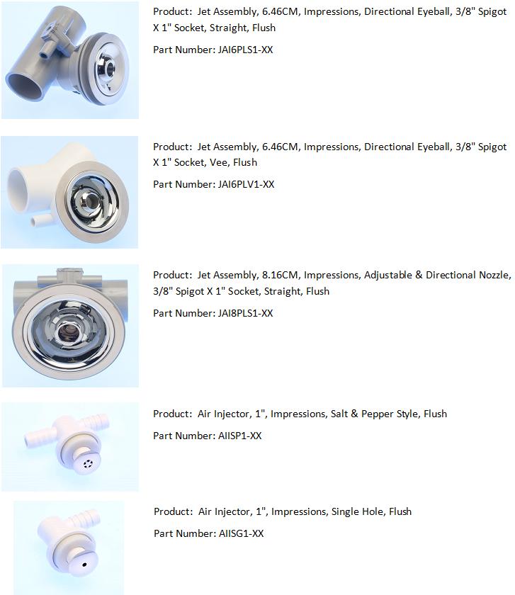
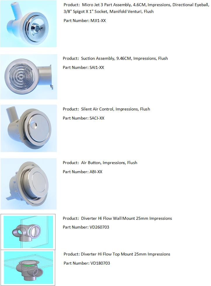
6 Page3 PRODUCT TECHNICAL DATA SHEET IDENTIFICATION: PART NUMBER PRODUCT NAME JAI6SPL1-XX Body Impressions 25x10 DESIGN SPECIFICATIONS TECHNICAL SPECIFICATIONS Spa jet body for use with directional and swirl jets WATER LINE CONNECTION 25mm Pipe Socket Non return valve fitted in airline AIRLINE CONNECTION 10mm Spigot Flush mount design MOUNTING HOLE SIZE 50 mm (2inch) Patented technology MATERIAL R12549 Rigid PVC Clearance in waterway to use former pipes COLOR Grey PACKAGING SERVICE INSTRUCTIONS Due to this product having no moving parts, and as long as the correct installation procedures have been followed there should be no requirement for service in the field COMPONENT SPECIFICATIONS Jet Body Mounting Flange Retainer PVC Stainless Steel PVC MATERIAL SAFETY DATA STANDARDS When installed insure the stainless steel mounting flange sits tight to the bath wall and there are no sharp edges on the stainless steel mounting flange that could cut the user Refer to page to manual for a list of standards this product is designed and manufactured to Always install the product in a manner that minimizes the amount of retained water in the pipe work and fittings
7 Page4 PRODUCT TECHNICAL DATA SHEET IDENTIFICATION: PART NUMBER PRODUCT NAME JAISPLS1-XX directional eyeball jet DESIGN SPECIFICATIONS Cartridge type eyeball spa jet for impressions product range PRODUCT PART SPECIFICATIONS ITEM PART No NAME MATERIAL FINISH 0ne piece cartridge assembly Stainless steel spring to create smooth eyeball rotation Positive lock to engage jet into jet body Adjustable in direction For chrome plate standards and finish refer to "Aesthetics Standard M " Easily removable for cleaning using tool PACKAGING 300 per carton SERVICE INSTRUCTIONS FLOW RATE GRAPHS This jet is designed to be easily removed as a one piece cartridge for cleaning or service. Using Tool MT0268 depress eyeball, clipping tool under edge of jet face adjacent to the eyeball and pull free. MATERIAL SAFETY DATA There are no known hazards with this product. Always insure correct installation procedures have been followed Kpa Flow Rates Pressures are measured at jet body not at pump. Pressure losses will occur in pipe system Litres/min
8 Page9 PRODUCT TECHNICAL DATA SHEET IDENTIFICATION: PART NUMBER PRODUCT NAME JAI8PLS1-XX Body c-lenda Maxi 25x10 DESIGN SPECIFICATIONS TECHNICAL SPECIFICATIONS Spa jet body for use with JAI8PLS1 jet WATER LINE CONNECTION 25mm Pipe Socket Non return valve fitted in airline AIRLINE CONNECTION 10mm Spigot Compact body MOUNTING HOLE SIZE 70mm (2.75 inch) Anti vortex deflector to maximize jet performance MATERIAL R12549 Rigid PVC Flush mount COLOR Grey Patented technology PACKAGING SERVICE INSTRUCTIONS Due to this product having no moving parts, and as long as the correct installation procedures have been followed there should be no requirement for service in the field COMPONENT SPECIFICATIONS Jet Body Mounting Flange Retainer PVC Stainless Steel PVC MATERIAL SAFETY DATA STANDARDS When installed insure the stainless steel mounting flange sits tight to the bath wall and there are no sharp edges on the stainless steel mounting flange that could cut the user Refer to page 36 of manual for a list of standards this product is designed and manufactured to Always install the product in a manner that minimizes the amount of retained water in the pipe work and fittings
9 Page10 PRODUCT TECHNICAL DATA SHEET IDENTIFICATION: PART NUMBER PRODUCT NAME JAI8PLS1-XX adjustable and directional jet impressions DESIGN SPECIFICATIONS JAI8PLS1 jet for impressions product range PRODUCT PART SPECIFICATIONS ITEM PART No NAME MATERIAL FINISH Flush mount design Large bore jet One piece cartridge Adjustable in direction Easy twist to adjust flow rate For chrome plate standards and finish refer to "Aesthetics Standard M " PACKAGING SERVICE INSTRUCTIONS FLOW RATE GRAPHS 90 This jet incorporates a bayonet locking system, Twist the jet face in an anticlockwise direction and the complete one piece jet assembly will unlock and ramp out of the retainer. MATERIAL SAFETY DATA Kpa Flow Rate Pressures are measured at jet body not at pump. Pressure losses will occur in pipe system 20 There are no known hazards with this product. Always insure correct installation procedures have been followed Litres/min
10 Page11 PRODUCT TECHNICAL DATA SHEET IDENTIFICATION: WARNING The Harford loop must be mounted less than 30mm below the overflow point of the bath when filled with water PART NUMBER PRODUCT NAME SAI1-XX Suction elbow impressions 40mm DESIGN SPECIFICATIONS TECHNICAL SPECIFICATIONS Safe flow suction elbow for use with c-lenda product range WATER LINE CONNECTION 40mm Pipe Socket Compact design HARTFORD LOOP CONNECTION 5mm ID tube Protection against body and hair entrapment MOUNTING HOLE SIZE 75 mm (3inch) Hartford loop overflow prevention device MATERIAL R12549 Rigid PVC 40mm pipe flow rate COLOUR Grey Unique safety sensing device with no moving parts PACKAGING SERVICE INSTRUCTIONS Due to this product having no moving parts, and as long as the correct installation procedures have been followed there will be no requirement for service in the field COMPONENT SPECIFICATIONS Jet Body Mounting Flange Retainer Hartford Loop Connecting tube PVC Stainless Steel PVC ABS Not Supplied MATERIAL SAFETY DATA STANDARDS When installed insure the stainless steel mounting flange sits tight to the bath wall and there are no sharp edges on the stainless steel mounting flange that could cut the user. If the suction cover is removed all safety features will stop working! Refer to page 36 of manual for a list of standards this product is designed and manufactured to IMPORTANT THE TOP OF THE HARTFORD LOOP MUST NOT BE MOUNTED MORE THAN 30mm BELOW THE TOP OF THE BATH FLANGE.
11 Page12 PRODUCT TECHNICAL DATA SHEET IDENTIFICATION: PART NUMBER PRODUCT NAME SAI1-XX Suction assembly impressions DESIGN SPECIFICATIONS Flush Safe flow suction cover for Impressions product range Flush mount design PRODUCT PART SPECIFICATIONS ITEM PART No NAME MATERIAL FINISH A Suction Cover ABS Chrome Full 40mm pipe flow rate (tested to 400 l/min) Safety sensing design for hair and body entrapment Requires tool for removal Complies with AS3350 For chrome plate standards and finish refer to "Aesthetics Standard M " PACKAGING SERVICE INSTRUCTIONS FLOW RATE The cover can be removed by following the instructions on instruction manual. It is recommended this is carried out by a qualified service agent. Removal of the suction cover will render the spa unsafe for use MATERIAL SAFETY DATA The suction has been tested to flow in excess of 400 liters / min It is critical the suction cover is correctly fitted and not damaged in any way. Operating a spa without the cover fitted is not safe.
12 Page13 PRODUCT TECHNICAL DATA SHEET IDENTIFICATION: PART NUMBER PRODUCT NAME ABI-XX Air button impressions DESIGN SPECIFICATIONS Air button, can be both a flange mount or a wall mount and operates below water level without leaking TECHNICAL SPECIFICATIONS WATER LINE CONNECTION Not applicable Flush mount design AIRLINE CONNECTION 4mm Spigot Wall or Flange mount Operates below water level MOUNTING HOLE SIZE MATERIAL 38 mm (1.5 inches) R12549 Rigid PVC 100% watertight Incorporates silicone injection sealing system COLOR Grey PACKAGING SERVICE INSTRUCTIONS PRODUCT PART SPECIFICATIONS The impressions air button can be serviced from inside the bath by unlocking the trim and removing. This will allow access to the bellows and spring if required. MATERIAL SAFETY DATA When installed insure the stainless steel mounting flange sits tight to the bath wall and there are no sharp edges on the stainless steel mounting flange that could cut the user
13 Page14 PRODUCT TECHNICAL DATA SHEET IDENTIFICATION: PART NUMBER PRODUCT NAME SACI-XX Silent Air Control Impressions DESIGN SPECIFICATIONS Flush Air control for Impressions product range Flush mount design Flange or wall mount design TECHNICAL SPECIFICATIONS WATER LINE CONNECTION AIRLINE CONNECTION MOUNTING HOLE SIZE Not applicable 10NB Spigot 38mm (1.5 inches) Hartford loop to allow below level water mounting MATERIAL R12549 Rigid PVC Easy to turn High air flow SERVICE INSTRUCTIONS The c-lenda air control can be serviced from inside the bath by removing the cap and lifting out the oring support. This will allow access to the inside components of the product COLOR Grey PACKAGING THE MAXIMUM MOUNTING DISTANCE FROM THE OVERFLOW POINT OF THE BATH FLANGE DOWNTO THE CENTRE OF THE AIRCONTROL ON A WALL MOUNT INSTALLTION IS 65MM PRODUCT PART SPECIFICATIONS ITEM PART No NAME MATERIAL FINISH MATERIAL SAFETY DATA When installed insure the stainless steel mounting flange sits tight to the bath wall and there are no sharp edges on the stainless steel mounting flange that could cut the user DO NOT MOUNT THE AIR CONTROL MORE THAN THE MAXIMUM RECOMMENDED DISTANCE BELOW THE BATH FLANGE
14 INSTALL & SERVICE INSTRUCTIONS

 Drill Deburring Tool INSTALLATION METHOD THERE MUST")

15 Page17 The following instructions are intended as a guide and check list only. If the plumber assembling these products has better methods that ensure a quicker and safer installation then use those methods over these providing it is not to the detriment of the product. INSTALLATION INSTRUCTIONS JAI16PLS1 impressions body 25x10 TOOLS REQUIRED Tool Part No MT0168 Silicone Sealant 2 inch Hole Saw (50mm) Drill Deburring Tool INSTALLATION METHOD THERE MUST BE NO BURR ON EDGE OF HOLE, a burr could stop the mounting flange sitting down flush Apply an adequate amount of silicone to front flange of body Locate flange and stainless steel mounting flange into hole in bath Glue 25 pressure pipe into sockets Glue and fit airline Clamp airline CHECK LIST Did I apply enough silicone in a continuous bead around the body flange? Did I clean the edge of the hole to ensure no up stand could prevent the mounting flange sitting flat? Did I tighten the retainer enough? Is the stainless steel flange pulled down hard all around its edge? Are there sharp edges on the stainless steel mounting flange that could cut somebody?


16 Page18 The following instructions are intended as a guide and check list only. If the plumber assembling these products has better methods that ensure a quicker and safer installation then use those methods over these providing it is not to the detriment of the product. INSTALLATION INSTRUCTIONS MJI1-XX impressions directional jet TOOLS REQUIRED Service Tool, Part No MT0268 (for removal only) INSTALLATION METHOD Push jet into body 25x10 Insure Jet clips fully home and locked in place, CHECK EYEBALL IS NOT LOOSE Check action of eyeball by pivoting from side to side. Should be smooth action, not loose. REMOVAL FOR CLEANING OR SERVICE Using Service Tool MT0268, push eyeball back and clip tool under edge of jet face. Pull out with a firm action. Remove tool from centre of jet face Clean Jet, check spring ok and there are no broken parts, replace as above procedure. CHECK LIST Is the spring on the jet assembly? Is the jet locked fully in place? Does the jet sit flush in the mounting flange? Does the eyeball have spring tension on it so it pivots with a firm action? Are there sharp edges on the stainless steel mounting flange that could cut somebody?


17 Page20 Do not have this ready yet. DO NOT USE The following instructions are intended as a guide and check list only. If the plumber assembling these products has better methods that ensure a quicker and safer installation then use those methods over these providing it is not to the detriment of the product. INSTALLATION INSTRUCTIONS MJI1-XX impressions directional eyeball 19mm TOOLS REQUIRED installation Tool, Part No MT0168 Silicone Sealant 1.5 inch Hole Saw (38mm) Drill Deburring Tool INSTALLATION METHOD Drill hole through bath wall using 1.5 inch hole saw THERE MUST BE NO BURR ON EDGE OF HOLE, a burr could stop the mounting flange sitting down flush Apply an adequate amount of silicone to front flange of body Locate retainer and mounting flange into hole in bath Using Installation tool screw retainer into jet body. Hand tighten only DO NOT OVERTIGHTEN CHECK THAT THE EDGE OF THE MOUNTING FLANGE IS PULLED DOWN AND THERE IS NO SHARP EDGE Glue and fit airline Push 19mm flex pipe on barb spigot. Fit clamping clip to retain pipe CHECK LIST Did I apply enough silicone in a continuous bead around the body flange? Did I clean the edge of the hole to ensure no up stand could prevent the mounting flange sitting flat? Did I tighten the retainer enough? Is the stainless steel mounting flange pulled down hard all around its edge? Are there sharp edges on the stainless steel mounting flange that could cut somebody?

 Drill Deburring Tool INSTALLATION METHOD Drill hole through bath wall using 1.")
18 Page23 The following instructions are intended as a guide and check list only. If the plumber assembling these products has better methods that ensure a quicker and safer installation then use those methods over these providing it is not to the detriment of the product. INSTALLATION INSTRUCTIONS JAI8PLS1 Body impressions Maxi 25x10 TOOLS REQUIRED Installation Tool, Part No Silicone Sealant 2.75 inch Hole Saw (70mm) Drill Deburring Tool INSTALLATION METHOD Drill hole through bath wall using 1.5 inch hole saw THERE MUST BE NO BURR ON EDGE OF HOLE, a burr could stop the mounting flange sitting down flush Apply an adequate amount of silicone to front flange of body Locate retainer and mounting flange into hole in bath Using Installation tool screw retainer into jet body. Hand tighten only DO NOT OVERTIGHTEN CHECK THAT THE EDGE OF THE MOUNTING FLANGE IS PULLED DOWN AND THERE IS NO SHARP EDGE Push 19mm flex pipe on barb spigot. Fit clamping clip to retain pipe CHECK LIST Did I apply enough silicone in a continuous bead around the body flange? Did I clean the edge of the hole to ensure no up stand could prevent the mounting flange sitting flat? Did I tighten the retainer enough? Is the stainless steel flange pulled down hard all around its edge? Are there sharp edges on the stainless steel mounting flange that could cut somebody?


19 Page24 The following instructions are intended as a guide and check list only. If the plumber assembling these products has better methods that ensure a quicker and safer installation then use those methods over these providing it is not to the detriment of the product. INSTALLATION INSTRUCTIONS JAI8PLS1 Adjustable and Directional TOOLS REQUIRED Installation Tool, Part No INSTALLATION METHOD Push Jet into Jet Body Using Installation tool MT0168 rotate in clockwise direction, a clipping action indicates jet is locked in place Check jet is sitting flush with mounting flange. REMOVAL FOR CLEANING OR SERVICE Using Installation Tool insert drive legs in slots at bottom of jet and rotate anticlockwise Jet will unlock and ramp out of retainer and become free to remove. Clean Jet, check there are no broken parts, replace as per above procedure. CHECK LIST Is the jet locked fully in place? Is the jet flush with the mounting flange? Is the nozzle easy to twist to adjust flow? Does the nozzle pivot from side to side with a smooth action? Are there sharp edges on the mounting flange that could cut somebody?


20 Page25 The following instructions are intended as a guide and check list only. If the plumber assembling these products has better methods that ensure a quicker and safer installation then use those methods over these providing it is not to the detriment of the product. INSTALLATION INSTRUCTIONS SAI1-XX Suction Elbow impressions 40mm TOOLS REQUIRED I Tool, Part No Silicone Sealant 3 inch Hole Saw (75mm) Drill Deburring tool INSTALLATION METHOD Drill hole through bath wall using 3 inch hole saw THERE MUST BE NO BURR ON EDGE OF HOLE, a burr could stop the mounting flange sitting down flush Apply an adequate amount of silicone to front flange of body Locate locking flange and stainless steel Using Tool MT0168 tighten retainer into CHECK THAT THE EDGE OF THE trim into hole in bath elbow. Max torque 14nm MOUNTING FLANGE IS PULLED DOWNAND THERE IS NO SHARP EDGE THE HARTFORD LOOP UNIT MUST BE MOUNTED LESS THAN 30MM BELOW THE OVERFLOW POINT OF BATH Stick Hartford loop less than 30mm from the top Apply silicone bead to each side of Glue and fit 5mm ID tube as shown of the bath rim. Hartford loop to ensure component sticks feeding through retaining lugs to prevent SEE MAX DISTANCE ON SPEC SHEET. to bath permanently. accidental removal. CHECK LIST Did I clean the edge of the hole to ensure no up stand could prevent the mounting flange sitting flat? Did I tighten the retainer correctly? Is the mounting flange flange pulled down all around its edge? Was the dust wiped off the bath wall before sticking the Hartford loop to it? THE TOP OF THE HARTFORD LOOP IS LESS THAN 30MM BELOW THE TOP OF THE BATH FLANGE. Have I applied a silicone bead to each side of the Hartford loop to prevent it coming off? MAKE SURE THE CONNECTING TUBE IS SECURED CORRECTLY. IT MUST NOT BE ABLE TO BE REMOVED. Are there sharp edges on the stainless steel mounting flange that could cut somebody?


21 Page26 The following instructions are intended as a guide and check list only. If the plumber assembling these products has better methods that ensure a quicker and safer installation then use those methods over these providing it is not to the detriment of the product. INSTALLATION INSTRUCTIONS Suction Safe flow impressions TOOLS REQUIRED Self Tapping screw Pliers INSTALLATION METHOD Locate spigot on back of cover into hole in retainer centre. Push firmly and snap into place. DO NOT cover the safety sensing centre hole with a label or anything else. REMOVAL FOR REPLACEMENT Screw the self tapping screw in the centre hole approx 3 turns Grip firmly with pliers and pull cover off. Replace as above checking the centre hole is not damaged or blocked. CHECK LIST Is the cover locked fully in place? Can I lift it by the edge of the cover? Does the cover sit flush with the stainless steel mounting flange? The safety sensing hole has not been covered with anything? Are there sharp edges on the stainless steel mounting flange that could cut somebody?

 Silicone Sealant Drill Deburring Tool INSTALLATION METHOD Drill hole through bath wall using 1.")


22 Page27 The following instructions are intended as a guide and check list only. If the plumber assembling these products has better methods that ensure a quicker and safer installation then use those methods over these providing it is not to the detriment of the product. INSTALLATION INSTRUCTIONS ABI-XX Air button Impressions TOOLS REQUIRED 1.5 inch Hole Saw (38mm) Silicone Sealant Drill Deburring Tool INSTALLATION METHOD Drill hole through bath wall using 1.5 inch hole saw Remove any burr on top edge of hole with deburring tool. A burr could prevent stainless flange sitting flush. Remove nut from body and pass body through hole. SERVICE Refit nut and hand tighten, pulling the conical flange on the nut down onto the bath wall Inject silicone through one of the injection holes in the nut untill it oozes out the opposite hole. Loop the airline tube through the windows at the bottom and fit to the spigot to prevent it being pulled off. Unclip the air button trim as by twisting in anticlockwise direction as shown Remove trim and plunger, allowing access to bellows and spring. Inspect and replace if required. CHECK LIST Did I clean the edge of the hole to ensure no upstand that could prevent the mounting flange sitting flat? Did I tighten the nut correctly? Did I inject the silicone correctly so it oozed out the opposite hole? Is the mounting flange flange pulled down all around its edge? Are there sharp edges on the stainless steel mounting flange that could cut somebody?

 Silicone Sealant Drill Deburring Tool Solvent cement INSTALLATION METHOD Drill hole through bath wall using 1.")


23 Page28 The following instructions are intended as a guide and check list only. If the plumber assembling these products has better methods that ensure a quicker and safer installation then use those methods over these providing it is not to the detriment of the product. INSTALLATION INSTRUCTIONS SACI-XX Silent Air Control Impressions TOOLS REQUIRED 1.5 inch Hole Saw (38mm) Silicone Sealant Drill Deburring Tool Solvent cement INSTALLATION METHOD Drill hole through bath wall using 1.5 inch hole saw Remove any burr on top edge of hole with deburring tool. A burr could prevent stainless flange sitting flush. Remove nut from body and pass body through hole in bath. Refit nut and hand tighten, pulling the conical flange on the nut down onto the bath wall. SERVICE METHOD Inject silicone through one of the injection holes in the nut until it oozes out the opposite hole. Glue Hartford loop onto spigot, positioning Hartford loop in as close to vertical position as possible CHECK LIST Is the Hartford loop glued in place in a near vertical position. Did I clean the edge of the hole to ensure no up stand that could prevent the mounting flange sitting flat? Remove cap by lifting under edge as shown. Pick out centre piece as shown. Internal components can now be accessed for servicing. Did I tighten the nut correctly? Did I inject the silicone correctly so it oozed out the opposite hole? Is the mounting flange flange pulled down all around its edge? Are there sharp edges on the stainless steel mounting flange that could cut somebody? Inspect and replace if required, reassemble unit

24 Page31 The MT1068 is a multi-purpose tool designed to minimize the amount of different tools the installer is required to carry. Made of a strong glass filled nylon trhe tool has tensile strengths equivalent to aluminum with none of the associated problems than can occur by dropping tools in a bath. INSTALLATION INSTRUCTIONS Installation Tool #1 The 2 piece tool has has a head that can be removed and turned around to accomodate other products. Likewise the handle can be used on its own and is used as a tool for installing jet assemblies into bodies. See details below for identification of which end to use with the impressions procducts. IDENTIFICATION JAI6PLS1 Body Body mini 19mm Suction elbow hi flow diverter JAI8PLS1 Body Jet JAI8PLS1
25 HOW A HARTFORD LOOP WORKS AHartford loop is a device used to prevent under-the-rim fittings connected to air lines from overflowing and leaking behind the bath when it is overfilled. Below is a brief outline of how the Hartford loop achieves this. 1 2 The Hartford loop must be mounted as close to the underside of the flange as possible. There is a maximum distance that it can be mounted below the flange. Refer to the specification sheets for the specific product details. As the water level in the bath rises water flows up the airlines to the same level. Eventually the water spills over the lip of the inlet spigot to start filling the body of the fitting. 3 4 Equal Equal Equal Equal Once the level of the water in the fitting reaches the bottom of the outlet tube it creates a seal, trapping air in the body. As the bath water level rises further the water rises a similar amount in the outlet tube. When the bath is full to overflowing the water has risen to a point in the tube that is below the outlet level so it will not drain ontoo the floor under the bath. If the fitting has been installed to far beneath the bath rim the water will rise to the level of the outlet and drain onto the floor. When emptying the bath or operating the jets the water is sucked out of the body of the fitting. Ideally a Hartf ord loop should be positioned as close to vertical as possible. NuWhirl has tested the units to work at a slope of 25degs each side of vertical. Page34
26 HOW A SAFE-FLO SUCTION WORKS The safe-flstopping the suction pressure within seconds of being activated. suction prevents both body and hair entrapmen by using a unique sensing device that introduces air into the pump 1 2 Max Distance 30mm The suction assembly is mounted as shown above. A 5mm ID tube connects to a Hartford loop mounted up close to the underside of the bath flange. When the bath is filled with water the tube the 5mm ID tube from the suction also fills with water. The Hartford loop prevents the water from spilling out the top of the tube should the bath be overfilled. 3 4 Air in When the pump is running and long hair comes in near contact with the suction cover it is drawn towards the centre of the cover, restricting the small safety sensing hole in the centre. When this hole becomes restricted a venturi effect is created within the suction elbow, creating suction down the 5mm tube. Air is quickly drawn into the suction line causing the pump to cavitate and stop pumping, allowing the hair to be easily pulled away. Once clear the air stops getting drawn into the pumpp allowing the flow to start up again. Page35
27 STANDARDS and MATERIAL SPECIFICATIONS The Impressions range of spa bath fittiings are designed and manufactured in accordance with the following standards. Products Jet bodies and fittings Suctions AS1477 AS3350 ASME A M Material Specifications Rigid PVC Grade Type Hardness (ASTM D degC) Specific Gravity (ASTM D792) Tensile Strength (ASTM D412) Vicat Softening Pt Designed to meet pressure pipe requirements of AS1477 R12549 Calcium / Zinc D MPa 79.0deg 0 C ABS Grade Type Hardness (D-785) Specific Gravity (D-792) Tensile Strength (D-638) Vicat Softening Point (D ) PA727 Electroplating R MPa 105deg o C Stainlesss Steel Grade Finish(seen face) 304 BA Polished Finishess Electroplating Surfaces ASTASTM B 604 Aesthetics Standard M Page36
28 Summary of Critical Checks The mounting flanges are pulled down against the bath wall and will not present an edge that could cut somebody The Hartford loops and associated fittings are mounted at the correct height from the bath rim so that water cannot leak behind the bath. The retainers in the jets are correctly tightened An adequate amount of silicone is applied to the jet bodies so that they will seal correctly to the bath wall and not leak. The silicone injection nuts on the air button and air control have the silicone injected into them so that it oozes out the opposite hole ensuring a full seal. The jets and seen fitting are sitting flush with the mounting flange. The connecting tube on the air button and suction elbow are secured out of the way to prevent accidental removal when handling the bath Air lines are clamped to the top of the water lines in a manner that prevents the airline sagging and retaining water. The clamping rings are fitted to the 19mm flex tubing connections. The jets and fittings function as intended Page37
29 Page38 Notes
Installation guide Sahara & Sahara Plus
 Installation guide Sahara & Sahara Plus Installation requirements. Components for Billi Sahara 310, 320, 360 & 3120 Models Before commencing installation, ensure you have identified the following. 1. Underbench
Kallista Bath Flip Drain
 P21586 Page 1 of 7 THANK YOU FOR CHOOSING KALLISTA We appreciate your commitment to Kallista quality products. Please take a moment to review this manual before you install your Kallista product. If you
Quartz. Digital. Concealed with adjustable height and fixed head. Quartz Digital concelaed adjustable/fixed installation instuctions page 1
 Quartz Digital Concealed with adjustable height and fixed head The Waste Electrical and Electronic Equipment (Producer Responsibility) Regulation 2004 This product is outside the scope of the European
Installation guide Billi Quadra Sparkling & Quadra Sparkling Plus Tap option XL
 Installation guide Billi Quadra Sparkling & Quadra Sparkling Plus Tap option Installation requirements. Unpacking your Billi Quadra Sparking Unit Before commencing installation, carefully check for any
Installation Manual PS-200 & PS-201
 Installation Manual PS-200 & PS-201 Table of Contents Pre-Uncrating Checklist... 1 Verifying System Requirements... 2 Verifying System Direction... 2 Verifying the Electrical Requirements... 2 Removal
Quartz. Thermo. Concealed shower valve with adjustable head. Quartz Thermo installation guide page 1
 Quartz Thermo Concealed shower valve with adjustable head Quartz Thermo installation guide page 1 Shower systems Components Quartz Thermo built-in shower valve with adjustable head QZ3111 Quartz Thermo
Installation Manual PS-225 & PS-275
 Installation Manual PS-225 & PS-275 Table of Contents Pre-Uncrating Checklist... 1 Verifying System Requirements... 2 Verifying System Direction... 2 Verifying the Electrical Requirements... 2 Removal
The lowest profile jet system in the world
 The lowest profile jet system in the world The latest innovation in spa baths Born of 20 years endless pursuit of design excellence, MARKON have developed the new generation of spa bath fittings. Superior
Built-in Gas Hob CZ55554 CZ55571
 Built-in Gas Hob CZ55554 CZ55571 INSTALLATION AND OPERATING INSTRUCTIONS The product may differ from the one illustrated but the installation and operation procedure remains the same The product may differ
Assembly- and Usermanual. Rainmaker. Code No GB. Edition: 09/2007
 Assembly- and Usermanual Rainmaker Code No. 99-97-1729 GB Edition: 09/2007 Table of contents Page I 1 Overview and system specifications.................................. 1 1.1 Purpose of Evaporative
Installation guide Billi Quadra & Quadra Plus XL, XT, XR tap options
 Installation guide Billi Quadra & Quadra Plus XL, XT, XR tap options Installation requirements. Components for Billi Quadra Compact, 420, 440, 460, 4100 & 4180 Models Before commencing installation, ensure
8707T Includes seat. 8745T Includes Bowl
 PRESQU ILE INSTALLATION INSTRUCTIONS P/S- VITREOUS CHINA P/S-TRAP TOILET S-TRAP 200mm / P-TRAP 180mm K-8707T/K-8707T-S BEFORE YOU BEGIN Please read these instructions carefully to familiarize yourself
BLADE BATH SHOWER MIXER DECK MOUNTED CHR WITH KIT INSTALLATION INSTRUCTIONS P BS-E A/2
 BLADE BATH MIXER DECK MOUNTED CHR WITH KIT 20007014600 INSTRUCTIONS P5-65511339-1-BS-E A/2 20007014600 INTRODUCTION DIMENSIONS Please read these instructions carefully and keep in a safe place for future
Technical data. Bathroom/shower room installations. Water services (WRAS approved)
") Technical data The Closomat toilet MUST be installed by a competent or qualified person. Explanation of symbols Safety instructions in this manual are identified by symbols. The safety instructions are
Technical data The Closomat toilet MUST be installed by a competent or qualified person. Explanation of symbols Safety instructions in this manual are identified by symbols. The safety instructions are
Installation Guide. Install your new sink with step-by-step instructions.
 Installation Guide Install your new sink with step-by-step instructions. Installation Guide Bath Sinks Drop-In Undermount Dual Flex Vessel Drains Bathtubs Freestanding Overflow and Waste Kit Rough-In Kit
Install Guide Billi Quadra & Quadra Plus (Gooseneck)
") Install Guide Billi Quadra & Quadra Plus (Gooseneck) Installation requirements. Components for Billi Quadra Compact, 440, 460 & 4100 Models Before commencing installation, ensure you have identified the
Install Guide Billi Quadra & Quadra Plus (Gooseneck) Installation requirements. Components for Billi Quadra Compact, 440, 460 & 4100 Models Before commencing installation, ensure you have identified the
4-1 1 / 2 " Tees / 2 " hole saw w/ 1/4" drill bit / 2 " Male slip plugs
 Section 1: Parts List 1-50 Flex PVC pipe 2-1 1 / 2 " Ball Valves 4-1/2" 90 degree elbows 4 - Lengths of 1/2" PVC 4 - Jet bodies 4 - Jet nozzles 4 - Female slip/female slip unions 2 - Female slip/fpt union
Installation Guide. Pedicure Spa D K-163, K-1006, K-1011, K-1012
 Installation Guide Pedicure Spa K-163, K-1006, K-1011, K-1012 1063564-2-D Important Information WARNING: When using electrical products, basic precautions should always be followed, including the following:
Pet. Easy Guide. VAX Ltd., Kingswood Road, Hampton Lovett, Droitwich, Worcestershire, WR9 OQH, UK - website:
 V-027P Rapide Pet User Guide 10/7/07 10:05 Page 14 EEC STATEMENT OF COMPLIANCE Manufacturer/EEC importer: VAX Limited, hereby on our own responsibility declare that the products V-027/V-027PT/V-027P/CCW-701
VISAGE INSTALLATION GUIDE
 VISAGE INSTALLATION GUIDE Images for illustration purposes only, product may differ. CONCEALED COMPONENTS 1. 1. 2. 2. 1. Gravity stored water systems only 2. Mains fed and separately pumped water systems
Cable Drain & Cable Drain Trim Kit
 INSTALLATION INSTRUCTIONS Cable & Cable Trim Kit P21581 & P21582 1 of 6 INSTALLATION INSTRUCTIONS Cable & Cable Trim Kit THANK YOU FOR CHOOSING KALLISTA We appreciate your commitment to Kallista quality
Kinetic. Logic. Astin. THERMOSTATIC INLINE CONTROL SHOWER VALVES Installation & aftercare instructions. Please retain for future reference
 THERMOSTATIC INLINE CONTROL SHOWER VALVES Installation & aftercare instructions Please retain for future reference DUAL INLINE CONCEALED VALVE SKN0201, SAS0201, SLG0202 SKN0202, SAS0205 TRIPLE INLINE CONCEALED
AirBath Hydro-Massage Tubs UL1795 Installation and Operating Instructions
 Tools you might need for proper installation Galvanized Nails or Screws - For Units with a Tiling Flange Four Foot Level Shims Caulking Gun Screw Gun Adhesive Thank you for purchasing the Praxis AirBath
HydroCycle Vertical Aeroponic Systems
 HydroCycle Vertical Aeroponic Systems 2018 Growers Supply All Rights Reserved. Reproduction is prohibited without permission. *Actual system may differ from system shown. 113593 8' Vertical System (44
Instruction Manual. AquaT Marine Toilet. Manual Operated. Toa_manual_ indd :17:35
 Instruction Manual AquaT Marine Toilet Manual Operated Toa_manual_060906.indd 1 06-10-13 11:17:35 Johnson Pump Marine Toilet, Manual Applications Johnson Pump Comfort and Compact bowl manually operated
Acrylic Claw Foot Tub
 Acrylic Claw Foot Tub Wrench or socket Drill & Bits Parts Recommended 2-2 x12 boards 4 Lag Bolts 4 Flat Washers Be sure to re-inforce the floor before securing tub. We recommend 2-2 x12 s securely fastened
Acrylic Claw Foot Tub
 Acrylic Claw Foot Tub Wrench or socket Drill & Bits Parts Recommended 2-2 x12 boards 4 Lag Bolts 4 Flat Washers Be sure to re-inforce the floor before securing tub. We recommend 2-2 x12 s securely fastened
Thermostatic bar mixer valve with adjustable head Installation guide
 Bar valve Thermostatic bar mixer valve with adjustable head Installation guide Index Introduction p.3 - Safety information p.3 - Product specification p.3 Connection to supplies p.3 - Flushing p.4 - Filters
Clean Water Made Easy. CWS Time Clock Softener Installation & Start Up Guide. Questions?
 Clean Water Made Easy www.cleanwaterstore.com CWS Time Clock Softener Installation & Start Up Guide Thank you for purchasing a Clean Water System! With proper installation and a little routine maintenance
METIS. Installation instructions. Riser rail kit INSTALLERS PLEASE NOTE THESE INSTRUCTIONS ARE TO BE LEFT WITH THE USER.
 METIS Riser rail kit Installation instructions INSTALLERS PLEASE NOTE THESE INSTRUCTIONS ARE TO BE LEFT WITH THE USER 2180531A September 2006 CONTENTS Page General installation notes 1 Main components
User Guide. Please read carefully before use. Your Hoover Guarantee. Your Hoover Guarantee. Contents. IMPORTANT Safety Reminders
 Your Hoover Guarantee Contents Your Hoover Guarantee During year 1 HOOVER engineers will replace or repair all defective parts free of charge, except for parts subject to fair wear and tear such as belts,
Miniboil Boiling Only
 Zip HydroTap Installation and Operating Instructions Miniboil Boiling Only Boiling and Ambient drinking water for kitchens and the home. Model 39137 - Elite Order Code - 1000AU0M0N1R Page 1 of 16 Zip Hydro
PolyMax H1-10 Dutch Bucket System
 112529 PolyMax H1-10 Dutch Bucket System *Actual system may differ. PolyMax Dutch Buckets Versatile PolyMax Dutch Buckets are ideal for both small- and large-scale hydroponic growing. STK# DIMENSIONS 112529
Self-help Temperature Adjustment
 Self-help Temperature Adjustment The Shower Valve temperature is pre-set to 42 C, but on certain installations the temperature may need to be adjusted. Note: The hot water supply must be above 60 C. Turn
MIDAS. Installation instructions 110/220
 MIDAS Installation instructions 110/220 INDEX INTRODUCTION Page 3 Safety information Page 3 Product specification Page 3 Important information CONNECTION TO SUPPLIES Page 4 Flushing Page 4 Filters Page
THERMOSTATIC SHOWER CONCEALED VALVE - TWIN WITH DIVERTER & TRIPLE WITH DIVERTER
 THERMOSTATIC SHOWER CONCEALED VALVE - TWIN & TRIPLE INSTALLATION INSTRUCTIONS INTRODUCTION This thermostatic valve is suitable for use with all water systems with an operating pressure of 2-5 bar (beyond
Lavatory Faucet INSTALLATION INSTRUCTIONS P24490-CR, P24490-LV, P24491-CR, P24491-LV, P24492-CR, P24492-LV, P24700, P24705, P24706, P24736, P24800
 P24490-CR, P24490-LV, P24491-CR, P24491-LV, P24492-CR, P24492-LV, P24700, P24705, P24706, P24736, P24800 2018 1 of 7 KALLISTA THANK YOU FOR CHOOSING KALLISTA We appreciate your commitment to KALLISTA quality
Dream DCV. Thermostatic Dual control mixer valve range. Installation guide
 Dream TM DCV Thermostatic Dual control mixer valve range Installation guide Index Introduction p.3 - Safety information p.3 - Product specification p.3 Connection to supplies p.4 - Pipe sizing p.4 - Flushing
CONCEALED THERMOSTATIC SHOWER MIXER VALVE installation & aftercare instruction
 TROUBLE-SHOOTING CONCEALED THERMOSTATIC SHOWER MIXER VALVE installation & aftercare instruction Problem After installation shower only runs HOT or COLD and will not mix. Solution Hot & Cold supplies are
Food Waste Disposer Instruction Manual
 Food Waste Disposer Instruction Manual NOTE: IMPORTANT: CAUTION: This Food Waste Disposer has been designed to operate on 220-240V~, 50/60 Hz exclusively. Using any other voltage or Hz adversely affects
PIPE DREAMS 96. Aeroponic Garden IMPORTANT:
 1 WARNING: BEFORE PUTTING WATER PUMP INTO OPERATION FILL UP NUTRIENT TANK TO TOP OF PUMP. THE PUMP MUST NEVER RUN DRY OTHERWISE, WARRANTY WILL BE DECLINED. READ FILLING INSTRUCTIONS BEFORE USE. Welcome
Ambassador. Installation guide & user instructions. Please ensure that this document is handed to the user after installation is completed
 Ambassador Installation guide & user instructions Please ensure that this document is handed to the user after installation is completed 2 Contents Introduction p.4 - Safety information p.4 - Product specification
Page 1 of 18. Part# /5/2013
 Part# 1002655-06 8/5/2013 This manual contains important information concerning the installation and operation of the gun washers listed above. Read manual thoroughly and keep for future reference INSTRUCTIONS
WS1 Softener Installation & Start-Up Guide
 WS1 Softener Installation & Start-Up Guide Thank you for purchasing a Van Isle Conditioner. With proper installation and a little routine maintenance your system will be providing treated water for many
Installation guide Billi B-3000 Sparkling Dual levered slimline tap option
 Installation guide Billi B-3000 Sparkling Dual levered slimline tap option Installation requirements. IMPORTANT: This Billi appliance is to be installed by a licensed trades person in accordance with AS/NZS
Food Waste Disposer Instruction Manual
 Food Waste Disposer Instruction Manual See insert for specific information about your new disposer NOTE: IMPORTANT: CAUTION: This Food Waste Disposer has been designed to operate on 110-120 Volt, 60 Hz
INSTALLATION MANUAL FOR MODELS: TERAZZA, TRACCIO, MILANO, CERRATO
 INSTALLATION MANUAL FOR MODELS: TERAZZA, TRACCIO, MILANO, CERRATO TABLE OF CONTENTS ROOM SPECIFICATIONS ELECTRICAL SPECIFICATIONS PLUMBING SPECIFICATIONS TECHNICAL SPECIFICATIONS INTRODUCTION ASSEMBLY
SUBCOURSE EDITION EN US ARMY ENGINEER SCHOOL PLUMBING FIXTURES (PLUMBING IV)
") SUBCOURSE EDITION EN5113 5 US ARMY ENGINEER SCHOOL PLUMBING FIXTURES (PLUMBING IV) US ARMY PLUMBER MOS 51K SKILL LEVELS 1 AND 2 COURSE PLUMBING FIXTURES (PLUMBING IV) SUBCOURSE NO. EN5113 US Army Engineer
SUBCOURSE EDITION EN5113 5 US ARMY ENGINEER SCHOOL PLUMBING FIXTURES (PLUMBING IV) US ARMY PLUMBER MOS 51K SKILL LEVELS 1 AND 2 COURSE PLUMBING FIXTURES (PLUMBING IV) SUBCOURSE NO. EN5113 US Army Engineer
INSTALLATION. Glass Panel Doors (select models) CAUTION
 CAUTION") Location Do not install refrigerator near oven, radiator or other heat source. If not possible, shield refrigerator with cabinet material. Do not install where temperature falls below 55 F (13 C) or rises
Location Do not install refrigerator near oven, radiator or other heat source. If not possible, shield refrigerator with cabinet material. Do not install where temperature falls below 55 F (13 C) or rises
Thermostatic exposed shower valve and bath/shower mixer systems Installation guide
 Midas Thermostatic exposed shower valve and bath/shower mixer systems Installation guide 2 Index Introduction p.4 - Safety information p.4 - Product specification p.4 Connection to supplies p.4 - Flushing
HydroCycle Vertical Aeroponic Systems
 HydroCycle Vertical Aeroponic Systems 2018 Growers Supply All Rights Reserved. Reproduction is prohibited without permission. 113700 4' Vertical System (24 Grow Sites) Revision date: 01.10.18 1 Important
CEILING FAN OWNER S MANUAL
 Style that revolves around you. CEILING FAN OWNER S MANUAL Total fan weight *53 lbs. WEXFORD 11/05 WARNING: Read and follow these instructions carefully and be mindful of all warnings shown throughout.
HW3 Handwash Installation and Operating Instructions
 HW3[16]instructions 10/12/15 14:05 Page 1 HW3 Handwash Installation and Operating Instructions IMPORTANT SAFEGUARDS SPECIFICATION: HW3 RATING: 230-240V, 3000W, ~50Hz; DIMENSIONS: 170w x 190h x 80d mm;
INSTALLATION INSTRUCTIONS
 INSTALLATI INSTRUCTIS Trent Thermostatic Two Outlet Concealed Shower Valve, Fixed Shower Arm, Handset & Holder with Hose - TF3S Options: urlington has 2 different style handles for your selection, when
INSTALLATION MANUAL. Manufactured by AQUA-AIR MANUFACTURING. (801) or (800) FAX (801)
 or (800) FAX (801)") INSTALLATION MANUAL Manufactured by AQUA-AIR MANUFACTURING 542 W. 47 Confluence East 800 South, Ave., Salt Ivins, Lake Utah City, 84738 Utah 84123 (801) 265-9699 or (800) 916-5777 FAX (801) 268-3856 (435)
INSTALLATION MANUAL Manufactured by AQUA-AIR MANUFACTURING 542 W. 47 Confluence East 800 South, Ave., Salt Ivins, Lake Utah City, 84738 Utah 84123 (801) 265-9699 or (800) 916-5777 FAX (801) 268-3856 (435)
INSTALLATION MANUAL FOR MODELS: SOVANNA, BREZZA, TERRACINA, VENADO
 INSTALLATION MANUAL FOR MODELS: SOVANNA, BREZZA, TERRACINA, VENADO 1 STRADA, TERCERA, SEDONA, MARVIN STEAM SHOWERS SPECIFICATION SHEET 87.8 30 24 SOVANNA, VENADO, BREZZA, TERRACINA STEAM SHOWER UNIT DIMENSIONS
How To: PREPARATION REPLACE A KITCHEN SINK
 Skill Level: INTERMEDIATE Give these projects a try if you're a confident DIYer with a good working knowledge of a variety of tools. They can take a day or more to complete. If you can build a birdhouse
Bob-White Systems: AUTOMATED BOTTLE FILLER
 Bob-White Systems: AUTOMATED BOTTLE FILLER PRODUCT CAPPER MANUAL General Safety Rules WARNING: READ ALL INSTRUCTIONS. Failure to follow the safety rules listed below and other basic safety precautions
FOOD WASTE DISPOSER OWNER S GUIDE
 FOOD WASTE DISPOSER OWNER S GUIDE See insert for specific information about your new disposer NOTE: IMPORTANT: CAUTION: This Food Waste Disposer has been designed to operate on 110-120 Volt, 60 Hz exclusively.
Closomat Lima Vita installation & user guide
 Closomat Lima Vita installation & user guide design manufacture supply install service recycle Technical data The Closomat toilet MUST be installed by a competent or qualified person. Explanation of symbols
INSTALLATION INSTRUCTIONS
 Tay Thermostatic Bath Shower Mixer Deck Mounted with Swivel Shower Arm - T2DS Options: INSTALLATION INSTRUCTIONS Burlington has 2 different style handles for your selection, when using these additional
Hydrotherapy Jets (Remote Water Quality System)
") Page 1 of 6 Parts List (_) - 50 Roll of Flex PVC pipe 1-3/4 HP Circulating Centrifugal Pump 1 25 Roll of Flex PVC pipe 4-1 1 / 2 " Tees 2-1 1 / 2 " Ball Valves 2 - Female slip couplers 4-1/2" 90 degree
Page 1 of 6 Parts List (_) - 50 Roll of Flex PVC pipe 1-3/4 HP Circulating Centrifugal Pump 1 25 Roll of Flex PVC pipe 4-1 1 / 2 " Tees 2-1 1 / 2 " Ball Valves 2 - Female slip couplers 4-1/2" 90 degree
JOHN DEERE GATOR HPX/XUV 2 PASSENGER HEATER INSTALLATION INSTRUCTIONS (p/n: 9PH20S30)
") P. 1 of 12 JOHN DEERE GATOR HPX/XUV 2 PASSENGER HEATER INSTALLATION INSTRUCTIONS (p/n: 9PH20S30) Item: Qty: Description: 1 2 1 x 1 x 5/8 Tee Fitting 2 2 Plastic Snap-in Hose Grommet 3 4 1-1/2" Hose Clamps
P. 1 of 12 JOHN DEERE GATOR HPX/XUV 2 PASSENGER HEATER INSTALLATION INSTRUCTIONS (p/n: 9PH20S30) Item: Qty: Description: 1 2 1 x 1 x 5/8 Tee Fitting 2 2 Plastic Snap-in Hose Grommet 3 4 1-1/2" Hose Clamps
INSTALLATION AND OPERATION. -, 3. -is INSTRUCTIONS FOR COOLAIR S EVAP-PAD COOLING SYSTEM. Coo/ah AMERICAN COOLAIR CORPORATION
 I -, 3. -is INSTALLATION AND OPERATION INSTRUCTIONS FOR COOLAIR S EVAP-PAD COOLING SYSTEM e Coo/ah AMERICAN COOLAIR CORPORATION TABLE OF CONTENTS PAGE I. CONCEPT OF EVAPORATIVE COOLING....2 II. RECOMMENDEDTOOLS......3
OWNER S GUIDE SEQUENTIAL THERMOSTATIC SHOWER VALVE. 150mm Inlet Pipe Centres. Shower Control. Handles and. may differ depending.
 SEQUENTIAL THERMOSTATIC SHOWER VALVE 150mm Inlet Pipe Centres Shower Control Handles and Concealing Plate may differ depending on Model OWNER S GUIDE ISSUE 02 These instructions cover all exposed or concealed
REVERSE OSMOSIS DRINKING WATER SYSTEM
 REVERSE OSMOSIS DRINKING WATER SYSTEM 10/10 1 2 Introduction To The Sierra Congratulations on your purchase of the Nimbus Sierra reverse osmosis system. When properly maintained, this system will provide
Vertical Termination Part No: 3CGRVT 16 7/8" 18 Vent Pipe Extension Part No: 3CG18 9 7/8" Wall Hanger Part No: 3CGWH 7 7/8" 7 3/8"
 Corr/Guard Direct Vent Water Heater Vent/Air Intake System Installation and service must be performed by a qualified installer, service agency or the gas supplier. Installation must meet all state and
Wave. BATH SHOWER MIXER MONOBLOC With Kit Deck Mounted
 Wave BATH SHOWER MIXER MONOBLOC With Kit Deck Mounted WAVE MONO BATH SHOWER MIXER 20004011860 INSTRUCTIONS B For any further information please contact Bathstore on: 0845 873 8843 Or visit our web-site
Atmos EasySolar. Installation Instructions for. In-roof and flat roof installation with flat plate collectors
 Atmos EasySolar Installation Instructions for Atmos EasySolar In-roof and flat roof installation with flat plate collectors Atmos Heating Systems West March Daventry Northants, NN11 4SA Tel: 01327 871990
Look for Service Centres, Point of Sale addresses and other information on: Version: Date: Mai 2011 Tools required:
 Description: C250 S/CS Electric Valve Part number: 23709 information on: www.thetford.eu Version: V2 Date: Mai 2011 Tools required: Remove Waste holding tank Remove bowl retainer bracket closest to the
Thermostatic Concealed Shower Valve
 Thermostatic Concealed Shower Valve Product may differ from image. Please retain this booklet for future aftercare reference Component Breakdown - Three Handle Valve Component breakdown Two Handle Valve
Basin Mixer. Installation & Aftercare Instructions. Please retain for future reference.
 Basin Mixer Installation & Aftercare Instructions Please retain for future reference. This guide covers the installation of all basin mixer varients. Please select the installation diagram suited to the
~256. Ventilator. Float valve. Plugged end (INLET) Straight connection DN kpa: 1.20 l/s (instantaneous value)
 Straight connection DN kpa: 1.20 l/s (instantaneous value)") Date: 05 May 2009 Doc. 002190-2 TECHNICAL DATA 6543521 UNIT 2L, CONNECTION UPWARDS Mini-check Straight connection DN50 Rubber bend DN40 Connection DN40 83 ~195 35 Max. 3m ~256 Ø90 Evac Noback OUTLET Discharge
Date: 05 May 2009 Doc. 002190-2 TECHNICAL DATA 6543521 UNIT 2L, CONNECTION UPWARDS Mini-check Straight connection DN50 Rubber bend DN40 Connection DN40 83 ~195 35 Max. 3m ~256 Ø90 Evac Noback OUTLET Discharge
IMPORTANT SAFETY REMINDERS
 USEr manual IMPORTANT SAFETY REMINDERS This appliance should only be used for domestic cleaning, as described in this user guide. Please ensure that this guide is fully understood before operating the
Installation Instructions. For the 18 Built-In Dishwasher and Front Color Panels
 Installation Instructions For the 18 Built-In Dishwasher and Front Color Panels Printed in USA 154232102 Before You Begin DO NOT INSTALL DISHWASHER UNTIL YOU HAVE READ ALL INSTRUCTIONS. FOR YOUR SAFETY,
Installation Instructions
 Installation Instructions Self-Cleaning Radiant Electric Drop-In Range JDP47, JD968, JD900 If you have questions, call 1.800.GE.CARES or visit our website at: ge.com Before You Begin Read these instructions
Installation Instructions
 Installation Instructions Outdoor Installation Kit Models AD250 & AW250 Part No. 24097 Qualifications for installation of the kit: You must be able to read and understand all instructions provided with
INSTALLATION INSTRUCTIONS
 INSTALLATION INSTRUCTIONS Stour Thermostatic Exposed Shower Valve Single Outlet, Rigid Riser, Fixed Shower Arm & Soap Basket - BF2S Options: Burlington has a shower head of 3 different sizes for your selection.
Vertical Blinds. Step by Step Installation Instructions
 Vertical Blinds Step by Step Installation Instructions Everything You Need A Smooth Set-Up We want you to love your new window coverings and that includes having a smooth installation experience. We recommend
TREVI BLEND SINGLE LEVER SHOWER VALVES. INSTALLER After installation pass to user for future reference
 11 A4000, A4100 & A4110 TREVI BLEND PARTS LIST Ref. Description 1 Lever handle complete 1a/1b Nut and washer 2 Handle cover cap 3 Shield 4 Cover plate fixing screw 5.1 Cover plate for built in version
INSTALLATION INSTRUCTIONS UNDERCOUNTER DISHWASHERS
 INSTALLATION INSTRUCTIONS UNDERCOUNTER DISHWASHERS VIKING 111 Front Street Greenwood, Mississippi 38930 USA (662) 455-1200 IMPORTANT - PLEASE READ AND FOLLOW Before beginning - please read these instructions
STOP ACRYLIC TUB WITH INTEGRAL DRAIN PLANNING BEFORE YOU BEGIN TOOLS AND MATERIALS: GETTING STARTED INSTALLATION INSTRUCTIONS.
 BEFORE YOU BEGIN We recommend consulting a professional if you are unfamiliar with installing bathroom fixtures and plumbing. Signature Hardware accepts no liability for any damage to the floor, walls,
AVEO FREESTANDING V&B INSTALLATION-curves.indd 1 3/07/ :58:33 AM
 AVEO FREESTANDING 2 Contents Installation Notes 3 1 FITTING 3 1.1 UNPACKING 3 1.2 LIFTING 3 1.3 POSITIONING 4 1.4 CHECKING ROUGH IN DIMENSIONS 4 1.5 FITTING OFF THE WHIRLPOOL 5 1.6 CONNECTING THE DRAIN/OVERFLOW
aquaphyll TM QUAD Wall Mounted Chemical Dispensing System
 aquaphyll TM QUAD Wall Mounted Chemical Dispensing System w w w. p i o n e e r e c l i p s e. c o m aquaphyll tm QUAD wall mounted chemical dispensing system AquapHyll is the professional s choice in wall
Technical Data Sheet No. JS-SM-40 DOCUMENT TITLE 2.0 LITRE STORED PRESSURE WET CHEMICAL FIRE EXTINGUISHER
 PAGE: ISSUE: DATE: of A 00 07285 DOCUMENT TITLE 2.0 LITRE STORED PRESSURE WET CHEMICAL FIRE EXTINGUISHER MODELS: R2WC 0 07285 ISSUE A FIRST RELEASE NEW DOCUMENT WJJ LRL LHG REV DATE REVISION DESCRIPTION
Traditional Rigid Riser With Eight Inch Rose
 Traditional Rigid Riser With Eight Inch Rose BS20007013035 This product should only be fitted by a qualified plumber to NVQ (National Vocational Qualification) or SNVQ (Scottish National Vocational Qualification)
Varsity Concealed Shower System
 VARSITY CONCEALED SHOWER SYSTEM Installation & aftercare instructions Please retain for future reference Varsity Dual Function Concealed Shower System Product code SVA1615 Varsity Single Function Concealed
Lo-Carbon T-series Window & Roof Models
 Lo-Carbon T-series Window & Roof Models Installation & User Instructions WIRED 456165A (9 WW) 456168A (9 RF) 456173A (12 WW) 456176A (12 RF) WIRELESS 456169A (9 WW) 456172A (9 RF) 456177A (12 WW) 456180A
Manual and Thermostatic Power Shower Units
 520M/520TS Manual and Thermostatic Power Shower Units Installation instructions & User guide IMPORTANT: This booklet should be given to the customer after installation and demonstration. WARNING: Under
Installation Instructions
 Installation Instructions SELECTRONIC Hard-Wired AC Powered ICU Lavatory Proximity Faucet PRODUCT NUMBER 0. Certified to comply with ASME A..M 0 American Standard M 0. ICU Faucet shown Installed on American
Thermostatic shower valve with 2 way diverter, brass faceplate and handles - V51
 Thermostatic shower valve with 2 way diverter, brass faceplate and handles - V51 Important We recommend that this product is installed by a qualified professional plumber who is certified by NVQ (National
INSTALLATION GUIDELINES
 IMPORTANT: To ensure this product is installed properly, you must read and follow these guidelines. The owner/user of this product must keep this information for future reference. This product must be
Vacmobile 20/2. Instruction manual OPERATION & SERVICE
 This instruction manual provides general instructions for the Vacmobile 20/2 vacuum system. This machine may use either the Becker U4.20 or the PVR EM 20/B vacuum pump. Service information specific to
Smoothflow Student Fume Cupboard Installation Instructions
 Calibre Solutions Ltd 37 Manurere Rise, RD1 Matakohe 0593 Freephone: 0800 422 542 Phone: +64 21 684 273 Fax: +64 9 813 1319 Smoothflow Student Fume Cupboard Installation Instructions Refer Numbered Installation
Aqua & Instantaneous Electric Shower Installation Instructions SERVICE POLICY
 SERVICE POLICY In the event of you needing to contact the Galaxy Customer Service Department, the following procedure should be followed:- 3 5 Before telephoning the Galaxy Customer Service Department
Installation guide. Before installing read this guide first
 Installation guide Before installing read this guide first Introduction The operation of the Quooker The Quooker system consists of a small tank under the sink which is connected to the boiling-water tap.
Twin & Triple Exposed Thermostatic Shower Valve Installation & Operating Guide
 Twin & Triple Exposed Thermostatic Shower Valve Installation & Operating Guide Please leave this installation & user guide with the end user CONTENTS 1. Important information 1 2. Cleaning & Aftercare
Basin Set INSTALLATION INSTRUCTIONS
 P24130-CR, P24130-LV, P24131-CR, P24131-LV, P24400-CR, P24400-LV, P24401-CR, P24401-LV, P24402-CR, P24402-LV, P24500-LV, P24500-TT 1 of 5 INSTALLATION INSTRUCTIONS Thank You For Choosing Kallista We appreciate
- website: Vax Ltd., Kingswood Road, Hampton Lovett, Droitwich, Worcestershire WR9 0QH, UK
 V-026PT User Guide.qxd 7/9/06 15:13 Page 12 EEC STATEMENT OF COMPLIANCE Manufacturer/EEC importer: Vax Limited, hereby on our own responsibility, declare that the product V-026PT is manufactured in compliance
SERVICE MANUAL DISHWASHERS DIVA ACCESSIBILITY DISHWASHERS
 SERVICE MANUAL DISHWASHERS DIVA ELECTROLUX HOME PRODUCTS S.p.A. Publication no. Spares Operations Italy Corso Lino Zanussi,30 I - 33080 PORCIA /PN (ITALY) 599 38 70-09 Fax +39 0434 394096 EN DISHWASHERS