Chapter 4: Troubleshooting and Maintenance
|
|
|
- Sabrina Stokes
- 6 years ago
- Views:
Transcription
1 Training: HAPPY HCS-1201 Operations & Maintenance Chapter 4: Troubleshooting and Maintenance Basic Troubleshooting/ Sewing Interruptions Handling Sewing Interruptions: Thread breaks, hoop strikes, page 2 needle breaks, birdnests Troubleshooting thread breaks page 3 Maintenance and Upkeep Cleaning the rotary hook area page 4 Oiling: daily and weekly schedules Advanced Maintenance/Repair Techniques Rotary hook timing page 5 Hook retainer adjustment page 8 Setting/adjusting ti presser foot height ht page 9 Setting needle depth page 11 Error Code list and measures Note 5/13/2010: Information also current for firmware version Chapter 4: Troubleshooting & Maintenance 1
2 Recovering From Sewing Interruptions Your machine remembers the last-sewn stitch and position after most sewing interruptions, including thread breaks, hoop strikes, or shut-down. As long as the garment remains hooped, there is a good chance you can resume sewing once you ve fixed the problem. Note: Sudden power loss or emergency shut-down may result in slight mis-alignment. General Steps for Recovering from Sewing Interruptions 1. Fix the problem. Repair thread break/ replace needle, clear any blockage of thread or broken needle. Check that the bobbin and needle are re-threaded properly. 2. Verify sewing position. If the current needle does not appear to be over the correct position to resume sewing, press FUNC, then arrow down to POSITION, and press SET. If the sewing arm has been moved off the current sewing position, the carriage should return to this position now; otherwise it will not move. The stitch counter should also now reflect the current sewing position. 3. Back up if necessary. To overlap slightly to prevent gaps, press the STOP key until the satisfied. 4. Press START to resume sewing. If the Garment Has Become Mis-Aligned If you find the machine is slightly off-alignment when resuming sewing, follow this procedure: 1. Make note of the current sewing position (stitch#). At this point, also make a mental note (best-guess) of how far off the sewing position is, and in what direction. 2. Return to the design Origin position. Do this by pressing the FUNC key, selecting ORIGIN, and pressing SET. 3. Adjust the position of the hoop using the arrow keys based on your guess in step Return to the stitch # of the last-sewn position by pressing MENU, choosing POSITION, and pressing SET. Arrow down to the third option (stitch #), enter the stitch # from step 1 using the arrow keys and press SET. The sewing arm will now move to the lastsewn position. Press ESC to return to the main (drive) screen. 5. Test-sew sew or trace to verify before resuming sewing. If you re still slightly off, repeat steps 1-4 above. Chapter 4: Troubleshooting & Maintenance 2
3 Basic Troubleshooting: Thread Breaks We ve listed the most common causes for thread breaks are listed in a flowchart below, in order of frequency. Learn this checklist to keep your machine sewing trouble-free. Is the thread actually broken? YES Thread Break NO Check if: (1) bobbin out & reload or (2) if sensor is working/ properly threaded If the thread is actually broken, then: Check Thread Feed/Path: - thread path: is it correct at all points? - feed: is it smooth? Is it catching on anything? - Correct Needle orientation? Scarf should be at back. If path/feed is not the cause, then: Check condition/quality of thread: Old or mis-handled thread will break more frequently, especially when running in significant volume/speed. Use quality 40-wt polyester or rayon embroidery thread. If the bad thread is not the cause, then: Maybe a design problem if breaks in the same place(s). 1. Turn on the Stitch Sweeper, and reload the design, or 2. Have the digitizer fix the bad section or run a design cleanup to remove short stitches. If the design is not the cause, then: Check for damage/scarred surfaces from hoop strike or needle break. Broken bits of needle/other metal may scar/bur surfaces that contact thread i.e. needle, presser foot, needle plate, point area of rotary hook. Replace needle, use fine abrasive cord/cloth to polish these surfaces smooth again. Re-thread and sew again. Thread Breaks: Other Causes Sometimes less-obvious causes may contribute. These regular maintenance steps will further reduce causes for thread break: Keep Hook Area Clean Over time, lint, bits of thread and other debris + oil combine in the rotary hook area to coat important t sewing surfaces and interfere with sewing. Clean this area from time to time (more if you run your machine hard) with compressed air and/or a spray cleaner such as Hook Wash. Improper Thread Tension Over-tight AND over-loose tension either at the bobbin or the upper thread contribute indirectly to thread breaks. Rotary Hook Timing If you ve eliminated the most common causes, check to see if the rotary hook may have slipped slightly out of time. Read more on rotary hook timing, its significance, how to check and adjust later on in this chapter. Chapter 4: Troubleshooting & Maintenance 3
 1")
 (a) needle bars: 1 drop on each (for b, c, and")
 reciprocator and presser foot shafts, lower portion a race of the")


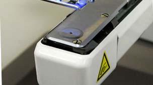
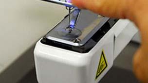
4 General Maintenance and Upkeep p Oiling: Use only white sewing machine oil There are 2 oiling schedules based on how frequently the machine is used: - Every 8 hours (or more if used heavily) 1 drop of oil on the race of the hook as shown. - Every 40 hours (as shown in diagram below, right) (a) needle bars: 1 drop on each (for b, c, and d, move head to Needle 1) (b) cup cut-out marked in yellow on machine (c) reciprocator and presser foot shafts, upper portion (d) reciprocator and presser foot shafts, lower portion a race of the hook b c Cleaning Clean the rotary hook area on a regular basis (especially with regular use) using solvent and compressed air. Helps prevent buildup of debris/oily film from lint/dust and oil spray. Reduces thread breaks & other sewing problems. Remove the needle plate first to get better access for cleaning. Removing the needle plate exposes more of the rotary hook area for more-thorough cleaning. d Chapter 4: Troubleshooting & Maintenance 4
5 Advanced Maintenance/Repair: Hook Timing Rotary Hook Timing The rotary hook is responsible for catching the top thread and creating a loop around the bobbin thread in order to form a stitch. To catch the top thread, the point of the rotary hook must arrive at a precise moment and distance to the needle (timing and clearance). When the timing and clearance are out of adjustment, the machine will generally experience missed stitches, looping, thread breaks and needle breaks. Checking Rotary Hook Timing and Clearance If you suspect that your rotary hook timing is off, you or your customer can check this easily yourself following these steps: 1. Power the machine on and allow it to continue to the main drive screen. 2. Select needle six (6). Do this using the keys on the control panel 3. Remove the needle plate and bobbin case. Do this by loosening each of the two (2) flathead screws with an offset screwdriver (provided in the machine s toolkit) Timing for HCS-1201 is at 25 degrees. 3. Remove the bobbin case. 4. Engage the needle. Do this by pressing the P.FOOT key, which lowers the presser foot. Then, grab the needle bar over the presser foot, and pull it down until it locks into place. 5. Turn shaft to 25 degrees. Do this with a 3mm Allen wrench. Turn the main shaft from the rear of the machine clockwise to L+25 (25 degrees). The needle should be down and in the basket area of the rotary hook at this point. With the needle engaged, dit should ldfll fall into this basket in front of the rotary hook and just behind the retaining finger. Chapter 4: Troubleshooting & Maintenance 5
 at 25 degrees: From the side of the machine, the point of the rotary hook pp y 0.1-0.")
6 Education Department Advanced Maintenance/Repair: p Hook Timing g Checking Rotary Hook Timing and Clearance (continued) TIMING (left-right) at 25 degrees: Viewing the hook assembly from the front of the machine, the point of the rotary hook should be hidden behind the needle. HOOK-NEEDLE CLEARANCE (front-back) at 25 degrees: From the side of the machine, the point of the rotary hook pp y mm from the back of the should be approximately needle (about the thickness of a business card). If the point is either touching or too far from the needle, the machine is not set correctly and will require adjustment. Note that the hook point passes behind the needle across the lower portion of the scarf. This clearance should be about the width of a business card. Chapter 4: Troubleshooting & Maintenance 6
 set screws that attach the rotary hook to the rotary hook shaft.")


7 Advanced Maintenance/Repair: Hook Timing Adjusting Rotary Hook Timing 1. Loosen the Rotary Hook. Do this by loosening each of the three (3) set screws that attach the rotary hook to the rotary hook shaft. Start with the larger screw on the milled flat spot of the hook s neck (lower right). Loosen screws just enough to break the hook loose on the shaft. Turn the wheel as necessary to access each screw from either side. (3/4 view) 3 set screws are located along the rear collar of the rotary hook. 3. Reset the dial to 25 degrees. Check that the needle is lowered into the rotary hook basket once more and that the main shaft dial is set 25 degrees. Adjust the main shaft as necessary by hand at rear of the machine. 4. Move hook and tighten screws. Adjust the timing and clearance simultaneously according to the diagrams on the previous page. Tighten screws carefully. If necessary, have an assistant hold the main shaft exactly at 25 degrees while positioning and tightening. Helpful Hints - Have a helper hold the timing wheel at 25 degrees with the T-handle wrench as you make your adjustments and tighten the screws. - Tighten each screw just enough to snug the hook back on the shaft, then re-check the timing, then tighten each screw further. Tighten all screws as firmly as you can manage. When practicing, re-check constantly as each screw is tightened. (side view) Turn the hook as necessary for easy access with a screwadriver. - Use a quality flat-tip screwdriver with a wide grip to help you apply enough torque to secure the rotary hook tightly on the shaft. Loosen this screw first before the other 2. Chapter 4: Troubleshooting & Maintenance 7
8 Mechanical Procedures: Hook Retainer Adjustment About the Hook Retainer (also called retaining finger) The hook retainer is located at the front of the rotary hook, near the top of the bobbin case. It is responsible for keeping the inner basket and bobbin case from spinning freely, while still allowing thread to pass across the front of the rotary hook. Adjusting the Hook Retainer Follow this short procedure to adjust the hook retainer: Hook retainer or retaining finger Stub of hook retainer 1. Remove the needle plate. Do this by loosening each of the two (2) flathead screws with an offset screwdriver. 2. Loosen the black screw. But do not remove. This will be the small button head hex screw toward the right corner, facing downward. 3. Move the retainer. Looking downward, set the stub located at the center of the retainer to approximately 0.8mm from the back edge of the rotary hook basket; or about halfway into the basket. The photo on the lower right shows a retaining finger close-up with proper clearance. 4. Tighten Screw. And check that the inner basket of the rotary hook does not rotate freely. Location of black set screw Photo of clearance of retaining finger stub from the notch in the hook. Location of black set screw Side view, retaining finger Chapter 4: Troubleshooting & Maintenance 8


9 Advanced Maintenance/Repair: Presser Foot Inspecting Presser Foot Height Follow this procedure to check proper presser foot height: 1. Engage the needle. Do this by pressing the P.FOOT key, which lowers the presser foot. Then, grab the needle bar over the presser foot, and pull it down until it locks into place. 2. Turn the shaft to 0 degrees. Dothiswithusinga3mmhexwrenchtoturnthetimingwheelattherearof the machine. 3. Check the clearance. The distance between the plate and pressure foot should be approximately 1.2mm; or slightly less than the width of a dime. Chapter 4: Troubleshooting & Maintenance 9


10 Advanced Maintenance/Repair: Presser Foot Adjusting Presser Foot Height Turn knob to index the head past needle, exposing the set screw for the presser foot shaft. 1. Take note of the adjustment t needed d by completing steps 1-3 on previous page. 2. Return the needle to the home position by pressing the T.CUT button or manually turning the shaft to 270 deg. as indicated d by the timing i wheel at the back. This MUST be done before performing step 4 below. 3. Remove retaining clip shown with a 1.5 mm hex wrench, from the end of the metal guide rail on the control panel side of the moving head. 4. Index the head past the needle 1 position to needle 0. Do this by turning the manual needle select knob clockwise. Remove this retaining clip with a 1.5 mm hex wrench. Exposed 2mm Hex set screw 5. Loosen the set screw and adjust the presser foot height. This is a phillips-type screw that fastens the pressure foot to the needle bar. Do not remove the screw. Adjust until the clearance measures approx. 1.2 mm or slightly less than the width of a dime. 6. Tighten the set screw. Chapter 4: Troubleshooting & Maintenance 10
. Do this using the keys on the control panel 3. Remove the needle plate and bobbin case.")


11 Advanced Maintenance: Needle Depth Inspecting Needle Depth 1. Power the machine on and allow it to continue to the main drive screen. 2. Select needle six (6). Do this using the keys on the control panel 3. Remove the needle plate and bobbin case. Do this by loosening each of the two (2) flathead screws with an offset screwdriver (provided in the machine s toolkit) 4. Remove the bobbin case. 5. Engage the needle. Do this by pressing the P.FOOT key, which lowers the presser foot. Then, grab the needle bar over the presser foot, and pull it down until it locks into place. 6. Turn shaft to 25 degrees. Do this with a 3mm hex wrench. Turn the main shaft from the rear of the machine clockwise to 25 degrees. The needle should be down and in the basket area of the rotary hook at this point. Note that the hook point passes behind the needle across the lower portion of the scarf. 7. Check needle height relative to the hook point. If needle depth is correct, the hook point will be passing behind the lower portion of the scarf. The optional Needle Depth Gauge makes needle depth easier to check: 1. Follow steps 1-4 above, but do not remove the needle plate not necessary. 2. Turn shaft to 5 degrees. This is bottom dead center for needle bar position in the sewing cycle. 3. Insert the needle depth gauge as shown. If depth is correct, needle point should scrape the top of the gauge. If too low, gauge insertion will not be possible. If too high, the gauge will not be able to contact the needle at all. Needle depth gauge Chapter 4: Troubleshooting & Maintenance 11
12 Error Code List and Measures page 1 Code Error Description Resolution/Remarks 001 Circuit Board Abnormality detected in control circuit board Power down machine and, after 10 seconds, power on again. 002 Power Source Power failure or abnormal voltage. Power down machine and, after 10 seconds, power on again. 004 System Memory System memory fault Power down machine and, after 10 seconds, power on again. 015 Inverter Trip Caused most frequently by uneven or inadequate AC power to the machine. Also may be main shaft motor overload, short, trouble w/main shaft drive unit or other main shaft motor related abnormality. 016 X-assembly alarm 017 Y-assembly alarm X-motor-related trouble, i.e. x-motor overload, short circuit, problem with motor drive unit Y-motor-related trouble, i.e. Y-motor overload, short circuit, problem with motor drive unit Cut power and turn main shaft by hand. If turns normally, power on again. Check inverter for Error. Should be set at 0.0. Also check power coming into machine. In our experience, this is triggered by inadequate or irregular voltage (I.e. fewer than 110v) coming from the AC outlet. Power off machine, test pantograph movement manually. Check for any abnormality throughout full range of motion. If none found, power on and test. May need to check PMD (pulse motor driver) Power off machine, test pantograph movement manually. Check for any abnormality throughout full range of motion. If none found, power on and test. May need to check PMD (pulse motor driver) 018 Main shaft error Main shaft will not turn. Currently, check for birdnesting at the rotary hook or any other blockage preventing main shaft from turning through its full rotation. Also check for needle bar boss jam as described on page 26 of this guide another possible cause. 020 Needle detect Machine not detecting current needle # correctly, or needle bar selection unit is off its stop position. Trouble with positiondetecting circuit board. Turn needle bar selector knob to until head is properly positioned at current needle position (check red alignment mark on knob with that on machine body). Chapter 4: Troubleshooting & Maintenance 12
13 Error Code List and Measures page 2 Code Error Description Resolution/Remarks 021 Needle move Motor for needle bar selection unit has stopped partway through its path. Follow same procedure listed for error Needle move Head unable to move due to malfunction Follow same procedure listed for error 020 of thread take-up lever or trouble of position-detecting circuit board 024 Needle Center Needle bar stop position is off-center; needle bar stop position is out of place. Follow same procedure listed for error Needle over Needle # out of range of actual needles Follow same procedure listed for error 020 on given machine. 026 Needle differ Mismatch between actual selected needle position and needle number showing in the control panel. Boot machine into maintenance mode and follow the procedure in this guide for re-setting Needle Memory. 030 Slow-speed Improper p speed adjustment at low Perform automatic speed re-set: (1) Choose OTHER from the mismatch speed. Speed does not decrease below main menu, then select SPEED. After warning, machine will turn 100rpm at low speed. main shaft slowly from stop to max speed (needle does not engage). 050 C point sensor Main shaft is stopped in a position other than "C" point (270 degrees) 051 L Sensor Timing detection board fault, or marred photo-sensor. Malfunction of "Lowest needle position" sensor on detection circuit board. 052 C Sensor Timing board detection fault, or marred photo-sensor. Malfunction of "Color change position" sensor on timing detection circuit board. Press SET and choose the AUTO option to allow machine to attempt to clear this error on its own. Barring that, choose MANUAL and turn the shaft back to 270 degrees. Check to see if photo sensor is clean or if the slit plate contacts sensor. Also check rotary hook area for bird-nesting and clear thread/blockage as necessary. Check to see if photo sensor is clean or if the slit plate contacts sensor. Also check rotary hook area for bird-nesting and clear thread/blockage as necessary. Chapter 4: Troubleshooting & Maintenance 13
14 Error Code List and Measures page 3 Code Error Description Resolution/Remarks 055 Safety Cover Switch not closed on left side of head due to safety cover being open Close safety cover or close switch. 060 X Limit Current design exceeds allowed width Check to make sure current pattern is digitized center-center center. Re- and/or or design position is positioned too check design position and size against currently-selected hoop and far to left or right of center. re-adjust as necessary. 061 Y Limit Current design exceeds allowed height and/or or design position is positioned too far to above or below center. 090 Miss reception Not implemented Not implemented 091 Failure to send Not implemented Not implemented 093 Data format Not implemented Not implemented Check to make sure current pattern is digitized center-center. Recheck design position and size against currently-selected hoop and re-adjust as necessary. 104 Miss function Corruption/mis-read of design data Re-transfer design again into machine and try again. 105 Dual function Corruption/mis-read of design data Re-load design again into memory 108 Improper read Not implemented Not implemented 110 Memory full During design transfer, memory has filled Delete unnecessary patterns from machine memory and try again. to capacity 111 Change Over Color change mis-match Design exceeds maximum # of 99 color changes or color change data is corrupt. Simplify or re-load design. 112 Data error Data error in design Re-load design 114 Id over # of patterns in control panel memory has exceeded the maximum of 99 Delete unnecessary patterns from machine memory and try again. Chapter 4: Troubleshooting & Maintenance 14
15 Error Code List and Measures page 4 Code Error Description Resolution/Remarks 118 Trace data over Error in design trace data creation Re-load design and try again. 120 Memory error Fault in retaining contents of pattern memory 130 Card error Incapable of disposing of memory card continuously If this occurs frequently, it is likely that CPU is faulty. Enter maintenance mode and run memory clear function to test memory and clear all data. Re-set machine system and speed, then try reloading design again. Update to firmware 1.11 or greater (for color LCD version of Voyager) which is more resilient against this sort of error. Re-seat memory card and try again. Ensure that you are using a compatible memory card d(compact tflash up to 1Gbi in size) )Failing the above, power off machine, power on again and re-try. Using same card, then different memory card. 131 Card not ready Card not set Same procedure as error code Bad card Not implemented Same procedure as error code Not found name Designated pattern not found Re-connect memory card into PC and re-save design again. 190 Cut blade Thread cut knife is not at stop position Look for bird s nest or other obstruction to moving knife. Clean out throat /needle plate and rotary hook area. Perform thread cut to attempt to clear. Failing that, press manual engagement lever and manually turn main shaft to check that knife opens and closes properly, continuing until knife re-seats properly. In doing so, check moving knife timing, verifying that knife opens at approx. 116 degrees. If needed, reset knife according to page 22 of this guide. 193 Catcher Thread catch hook is off its properlyretracted position. Limit switch to detect position is not "OFF". Check if not trimming properly. If thread is cut, ensure that catcher has returned to position, selecting either auto or manual. If so, cut and return thread catch hook to retracted position. If problem recurs, troubleshoot tposition of thread dholder, which h may mis-guide id catcher and cause it to miss the thread. Chapter 4: Troubleshooting & Maintenance 15
PLC-1700 Series PLC-1710, , 1760, , 1760L
 Post-bed, Unison-feed, Lockstitch Machine PLC-1700 Series PLC-1710, 1710-7, 1760, 1760-7, 1760L ENGINEER S MANUAL 40040656 No.E372-00 Introduction This Engineer s Manual is for technical service engineers.
IMPORTANT SAFETY INSTRUCTIONS
 CONTENTS 1.SPECIFICATIONS... 1 2.INSTALLATION... 1 3.INSTALLATION OF THE SYNCHRONIZER... 2 4.ASSEMBLY OF HAND WHEEL... 2 5.INSTALLATION OF HAND WHEEL... 2 6.INSTALLING THE BELT COVER... 3 7.ADJUSTING THE
ENGINEER S MANUAL No.01
 1-NEEDLE, UNISON FEED, LOCKSTITCH MACHINE (AUTOMATIC LUBRICATION) LU-1510 1-NEEDLE, UNISON FEED, LOCKSTITCH MACHINE WITH AUTOMATIC THREAD TRIMMER (AUTOMATIC LUBRICATION) LU-1510-7 1-NEEDLE, UNISON FEED,
Installation Instructions EFS Hand Washing Station
 Installation Instructions EFS Hand Washing Station Both water and soap are sequenced and dispensed from outlet. Override button allows for non potable, water-only dispensing. Lighted icons indicate the
Product instruction manual Easymount Wide Format Laminators
 Product instruction manual Easymount Wide Format Laminators The Easymount has been designed to be user friendly, however we strongly recommend you take a few minutes to read through this manual to ensure
Industrial Sewing Machine TECHNICAL MANUAL SEWING MACHINE HEAD. Electronic Pattern Sewing Machine. Model PLK-G1010 A180E593P03
 Industrial Sewing Machine TECHNICAL MANUAL SEWING MACHINE HEAD Electronic Pattern Sewing Machine Model PLK-G1010 A180E593P03 FOR SAFE USE Before the installation, operation, and inspection for this product,
Please read this manual before using the machine. Please keep this manual within easy reach for quick reference.
 INSTRUCTION MANUAL Please read this manual before using the machine. Please keep this manual within easy reach for quick reference. HIGH SPEED SINGLE NEEDLE STRAIGHT LOCK STITCHER Thank you very much for
MB-1800 Series INSTRUCTION MANUAL
 MB-800 Series INSTRUCTION MANUAL CONTENTS!. SPECIFICATIONS... @. NAME OF EACH COMPONENT.... Name of the main unit... #. INSTALLATION... $. PREPARATION OF THE SEWING MACHINE...7. Attaching the needle...
AMS-224EN4530R / AW-3 AMS-224EN6030R / AW-3 INSTRUCTION MANUAL
 AMS-224EN4530R / AW-3 AMS-224EN6030R / AW-3 INSTRUCTION MANUAL 1 CONTENTS 1. GENERAL...1 1-1. Specifications of AW-3...1 1-2. Configuration...2 2. INSTALLATION...4 2-1. Installation procedure...4 2-2.
Model PLK-G5050 PLK-G10050
 Industrial Sewing Machine TECHNICAL MANUAL SEWING MACHINE HEAD Electronic Pattern Sewing Machine Model PLK-G5050 PLK-G10050 A180E686P01 FOR SAFE USE Before the installation, operation, and inspection for
Please read this manual before using the machine. Please keep this manual within easy reach for quick reference.
 DA-927A DA-928A INSTRUCTION MANUAL Please read this manual before using the machine. Please keep this manual within easy reach for quick reference. TWIN NEEDLE / THREE NEEDLE FEED OFF THE ARM DOUBLE CHAIN
INSTALLATION. Glass Panel Doors (select models) CAUTION
 CAUTION") Location Do not install refrigerator near oven, radiator or other heat source. If not possible, shield refrigerator with cabinet material. Do not install where temperature falls below 55 F (13 C) or rises
Location Do not install refrigerator near oven, radiator or other heat source. If not possible, shield refrigerator with cabinet material. Do not install where temperature falls below 55 F (13 C) or rises
Industrial Sewing Machine TECHNICAL MANUAL SEWING MACHINE HEAD. Electronic Pattern Sewing Machine. Model PLK-G2516 A180E621P01
 Industrial Sewing Machine TECHNICAL MANUAL SEWING MACHINE HEAD Electronic Pattern Sewing Machine Model PLK-G2516 A180E621P01 FOR SAFE USE Before the installation, operation, and inspection for this product,
Industrial Sewing Machine TECHICAL MANUAL SEWING MACHINE HEAD. Electronic Pattern Sewing Machine. Model PLK-G1010 A180E593P02
 Industrial Sewing Machine TECHICAL MANUAL SEWING MACHINE HEAD Electronic Pattern Sewing Machine Model PLK-G1010 A180E593P02 FOR SAFE USE Before the installation, operation, and inspection for this product,
CONTENTS 1. SPECIFICATIONS SET-UP FOR THE OPERATOR MAINTENANCE... 34
 ENGLISH ii CONTENTS. SPECIFICATIONS... 2. SET-UP.... Installing the motor unit... 2. Installing the control box... 3. Installing the belt... 2 4. Adjusting the pulley cover... 2 5. Installation and adjustment
OWNERS MANUAL FOR MEC 300E ATA
 OWNERS MANUAL FOR MEC 300E ATA PLEASE READ AND FULLY UNDERSTAND THE INSTRUCTIONS PRIOR TO SETTING OR TUNING THE MACHINE. CAUTION: ANY MEC CLAY TARGET MACHINE MUST BE IN THE DISARMED STATE WITH THE BATTERY
EAGLE 2000B EAGLE 2000BE EAGLE 2000EBT MUST READ MANUAL PRIOR TO INSTALLING MACHINE
 EAGLE 2000B EAGLE 2000BE EAGLE 2000EBT MUST READ MANUAL PRIOR TO INSTALLING MACHINE Contents 1 Machine Safety Information 3 1.5 Safety Precautions Prior to Operating Machine 6 2 Machine Installation 7
AMS-224EN6060 / IP-420 INSTRUCTION MANUAL
 AMS-224EN6060 / IP-420 INSTRUCTION MANUAL * This Instruction Manual only describes the functions which are different from those of the AMS-224EN/IP-420. In order to use the AMS-224EN6060 safely, please
OPERATOR S MANUAL & PARTS LIST Ultra High Speed Burnishers
 OPERATOR S MANUAL & PARTS LIST Ultra High Speed Burnishers 1200 RPM Model M1200-3 1600 RPM Model M1600-3 2000 RPM Model M2000-3 U.S. Patent Number 4,845,798 U.S. Patent Number 4,756,042 U.S. Patent Number
PARTS LIST. Specification code: (JAI 45231) (JA) (JCA) (JUK) (JHBV)
 (JA) (JCA) (JUK) (JHBV)") PARTS LIST Specification code: 832-711-004 (JAI 45231) 832-712-005 (JA) 832-713-006 (JCA) 832-714-007 (JUK) 832-716-009 (JHBV) 14 13 1 2 6 10 12 9 11 8 7 3 5 4 7 1 KEY PART NO. NO. NAME 1 832649011 Needle
PARTS LIST Specification code: 832-711-004 (JAI 45231) 832-712-005 (JA) 832-713-006 (JCA) 832-714-007 (JUK) 832-716-009 (JHBV) 14 13 1 2 6 10 12 9 11 8 7 3 5 4 7 1 KEY PART NO. NO. NAME 1 832649011 Needle
FD Heavy Duty Feeder for FD 280 Tabbing System
 FD 280-10 Heavy Duty Feeder for FD 280 Tabbing System Operator Manual 8/2011 First Edition TABLE OF CONTENTS 1. INTRODUCTION... 1 1.1 Feeder Description... 1 1.2 Items Included... 1 1.3 Operating Manual
Installation and Care Instructions
 Installation and Care Instructions 2" Horizontal Aluminum Blinds MagnaView Tilt Feature CONTENTS Getting Started................................................ 1 Mount the Installation s....................................
57" Fiberglass Exhaust Fan with Cone
 OPERATORS MANUAL Fiberglass Exhaust Fan IMPORTANT: READ AND SAVE THESE INSTRUCTIONS Read all instructions carefully before attempting to assemble, install, operate or service the product described. Failure
DA-9270 TWIN NEEDLE (THREE NEEDLE) FEED OFF THE ARM DOUBLE CHAIN STITCHER. English
 FEED OFF THE ARM DOUBLE CHAIN STITCHER. English") TWIN NEEDLE (THREE NEEDLE) FEED OFF THE ARM DOUBLE CHAIN STITCHER English Thank you very much for buying a BROTHER sewing machine. Before using your new machine, please read the safety instructions below
TWIN NEEDLE (THREE NEEDLE) FEED OFF THE ARM DOUBLE CHAIN STITCHER English Thank you very much for buying a BROTHER sewing machine. Before using your new machine, please read the safety instructions below
A4 Manual Book. No. 15 Airport South Road, Jiaojiang District, Taizhou, Zhejiang, TEL: FAX:
 A4 Manual Book No. 15 Airport South Road, Jiaojiang District, Taizhou, Zhejiang, PRC TEL: 0086-576-88177782 88177767 FAX: 0086-576-88177787 E-mail: sales@chinajack.com www.chinajack.com Catalogue 1...2
FD 90 / FD 95 Rotary Perforators
 FD 90 / FD 95 Rotary Perforators 11/2018 OPERATOR MANUAL SECOND EDITION TABLE OF CONTENTS SPECIFICATIONS 1 SAFETY PRECAUTIONS 1 DESCRIPTION 2 INSTALLATION AND OPERATION 3 INFEED TABLE ADJUSTMENT 3 OUTFEED
BL Series INSTRUCTIONS
 BL Series Models: EX5204/BL514 EX5204/BL515 EX5214/BL524 EX5214/BL525 EXT5214/BL524 EXT5214/BL525 EX5404/BL614 EX5404/BL615 EX5414/BL624 EX5414/BL625 EXT5214H/BL528 EXT5214H/BL529 Automatic Backlatcher
LBX-2000 POWER STRAPPING MACHINE
 LBX-2000 POWER STRAPPING MACHINE Copyright 2008, Signode 439998 9/2008 (EN) CONGRATULATIONS Thank you for purchasing your LBX-2000 Walk-Up Strapping Machine. The LBX- 2000 Strapping Machine was designed
BARRACUDA 200ZW PORTABLE WALKING FOOT SEWING MACHINE INSTRUCTION MANUAL
 BARRACUDA 00ZW PORTABLE WALKING FOOT SEWING MACHINE INSTRUCTION MANUAL THE BARRACUDA 00ZW PORTABLE WALKING FOOT SEWING MACHINE INSTRUCTION MANUAL MATERIAL IS OWNED BY RELIABLE AND MAY NOT BE REPRODUCED
Industrial Sewing Machine TECHNICAL MANUAL MECHANICAL VERSION. Electronic Pattern Sewing Machine. Model PLK-E2010R A180E530P01
 Industrial Sewing Machine TECHNICAL MANUAL MECHANICAL VERSION Electronic Pattern Sewing Machine Model PLK-E2010R A180E530P01 FOR YOUR SAFETY! If you are operating the sewing machine for first time, please
WAILEA OWNER S MANUAL
 WAILEA OWNER S MANUAL The blades in each pack are matched for equal weight to assure smooth fan operation. If more than one fan is being installed, be careful not to mix blades from different cartons.
Installation and Care Instructions
 Installation and Care Instructions 2" Horizontal Aluminum Blinds MagnaView Tilt Feature Thank you for your purchase. Your new blinds have been custom built for you from the highest quality materials. Properly
MSK-8900M Industrial Sewing Machine. Instruction Manual
 MSK-8900M Industrial Sewing Machine Instruction Manual CONTENTS Operation instruction. Brief introduction. Main specifications. Main parts name 4. The method of installation 5 5. Pareparation before sewing
OPERATING & SERVICE PARTS MANUAL HDS-215 COMBINATION SHRINK SYSTEM
 OPERATING & SERVICE PARTS MANUAL HDS-215 COMBINATION SHRINK SYSTEM FOR HOT KNIFE AND IMPULSE MACHINES READ ALL INSTRUCTIONS CAREFULLY BEFORE OPERATING EQUIPMENT TABLE OF CONTENTS Electrical Requirements
DOCUMENT CREASING MACHINE
 DOCUMENT CREASING MACHINE OPERATORS MANUAL Morgana Systems Limited Snowdon Drive Winterhill Milton Keynes Buckinghamshire MK6 1AP United Kingdom Telephone: ( 01908 ) 608888 Facsimile: ( 01908 ) 692399
Please read this manual before using the machine. Please keep this manual within easy reach for quick reference.
 INSTRUCTION MANUAL Please read this manual before using the machine. Please keep this manual within easy reach for quick reference. SINGLE NEEDLE DIRECT DRIVE STRAIGHT LOCK STITCHER WITH THREAD TRIMMER
USER S MANUAL. SPS/E-1507 Series. Electronically Controlled Pattern Sewing Machine (Mechanical Part)
") R USERS MANUAL SPS/E-1507 Series Electronically Controlled Pattern Sewing Machine (Mechanical Part) R Best Quality Best Price Best Service 1. Thank you for purchasing our product. Based on the rich expertise
R USERS MANUAL SPS/E-1507 Series Electronically Controlled Pattern Sewing Machine (Mechanical Part) R Best Quality Best Price Best Service 1. Thank you for purchasing our product. Based on the rich expertise
INSTALLATION AND SERVICE MANUAL FOR THE SERIES 2000 & SERIES 3000 FAN SERIES GEN 2
 INSTALLATION AND SERVICE MANUAL FOR THE SERIES 2000 & SERIES 3000 FAN SERIES GEN 2 (PNEUMATIC CONTROL AND HYDRAULIC CONTROL) PUBLICATION No. 01900 Revision 2 Printed in Canada 1.1 INTRODUCTION Thank you
HEDMAN DI-50. Endorser Instructions. Hedman DI-50 Operators Guide
 HEDMAN DI-50 Endorser Instructions Hedman DI-50 Operators Guide 25-0132-20 TABLE OF CONTENTS 1. INTRODUCTION...1 1.1 DI-50 Description...1 1.2 Items Included...1 1.3 Safety Terms...2 1.4 Safety Precautions...3
USER MANUAL UN-200V / UN-200VH
 USER MANUAL UN-200V / UN-200VH CONTACT US PHONE/FAX Toll Free: 800.465.1004 Phone: 801.486.1004 Fax: 801.486.1007 ADDRESS LACO Technologies, Inc. 3085 West Directors Row Salt Lake City, UT 84104 WEB www.lacotech.com
BACK WASH INSIDE THE SPA
 BACK WASH INSIDE THE SPA Lower the temperature to 90 degrees and let the unit run approximately 10-15 minutes. This gives the heating element the chance to cool down. Now unplug the power pack Using a
Part 3: Service manual, class
 Contents Page: Part : Service manual, class 7-75. General.................................................. Gauges................................................. 4. Description and adjustment of the
Please read this manual before using the machine. Please keep this manual within easy reach for quick reference.
 INSTRUCTION MANUAL Please read this manual before using the machine. Please keep this manual within easy reach for quick reference. ELECTRONIC DIRECT DRIVE LOCKSTITCH BUTTON HOLER Thank you very much for
INSTALLATION AND SERVICE MANUAL FOR THE SERIES 2000 & SERIES 3000 FAN SERIES GEN 1
 INSTALLATION AND SERVICE MANUAL FOR THE SERIES 2000 & SERIES 3000 FAN SERIES GEN 1 (PNEUMATIC CONTROL AND HYDRAULIC CONTROL) PUBLICATION No. 01524 Revision 15 Printed in Canada 1.1 INTRODUCTION Thank
INSTALLATION & OPERATING INSTRUCTIONS
 INSTALLATION & OPERATING INSTRUCTIONS WARNING RISK OF ELECTRIC SHOCK. CONNECT ONLY TO A CIRCUIT PROTECTED BY A GROUND-FAULT CIRCUIT-INTERRUPTER. THE UNIT SHOULD BE INSTALLED BY A QUALIFIED SERVICE REPRESENTATIVE.
Panel Fan Series Operators Manual (Galvanized and Polymer)
") Panel Fan Series Operators Manual (Galvanized and Polymer) Galvanized Panel Fan with Three Wing Blade IMPORTANT: READ AND SAVE THESE INSTRUCTIONS Read all instructions carefully before attempting to assemble,
Panel Fan Series Operators Manual (Galvanized and Polymer) Galvanized Panel Fan with Three Wing Blade IMPORTANT: READ AND SAVE THESE INSTRUCTIONS Read all instructions carefully before attempting to assemble,
DDL-9000A Series. Direct-drive, High-speed, Lockstitch Machine with Automatic Thread Trimmer. High-end model of JUKI 1-needle lockstitch machines
 DDL-9000A Series Direct-drive, High-speed, Lockstitch Machine with Automatic Thread Trimmer DDL-9000A Series High-end model of JUKI 1-needle lockstitch machines A genuine sewing machine which makes the
Explorer CleaningPartsDirect.com Carpet Extractor. Operator and Parts Manual. Home Find... Go To.. Model No.: Can.
 Explorer 1500 Carpet Extractor Model No.: 608808 609231 Can. Operator and Parts Manual CleaningPartsDirect.com 662-393-3045 NOBLES 12875 RANSOM STREET HOLLAND MI 49424 U.S.A. CUSTOMER SERVICE: 1-800-365-6625
DDL-8700B-7 INSTRUCTION MANUAL
 DDL-8700B-7 INSTRUCTION MANUAL I CONTENTS I. SPECIFICATIONS... 1 II. SET-UP... 3 1. Installation...3 2. Installing the pedal sensor...4 3. Connecting the connector...4 4. How to install the power plug...5
MODEL COMPRESSOR SERVICE KIT For use on Midmark Power Air Oil-less Compressor Models P21, P22 & P32
 MODEL 77001616 COMPRESSOR SERVICE KIT For use on Midmark Power Air Oil-less Compressor Models P21, P22 & P32 WARNING: Unplug the compressor before beginning disassembly. CAUTION: Improper assembly or use
CBT Bowl & wrap replacement
 CBT bowl & wrap replacement 2 CBT BOWL & WRAP REPLACEMENT Revision History rev. level 01_03.14.2012 rev. level 02_03.19.2012 rev. level 03_03.23.2012 rev. level 04_05.30.2013 NOTE: due to the fact that
ENGLISH IP-110 TYPE F. No.00. * "CompactFlash(TM)" is the registered trademark of SanDisk Corporation, U.S.A.
 is the registered trademark of SanDisk Corporation, U.S.A.") ENGLISH IP-0 TYPE F Instruction Manual * "CompactFlash(TM)" is the registered trademark of SanDisk Corporation, U.S.A. No.00 40 CONTENTS. INSTALLING THE OPERATION PANEL... 2. CONNECTING THE CORD... 3.
ENGLISH IP-0 TYPE F Instruction Manual * "CompactFlash(TM)" is the registered trademark of SanDisk Corporation, U.S.A. No.00 40 CONTENTS. INSTALLING THE OPERATION PANEL... 2. CONNECTING THE CORD... 3.
H uline.com 80" AUTOMATIC STRETCH WRAP DISPENSER FILM DELIVERY SYSTEM MACHINE DIMENSIONS ELECTRICAL SPECIFICATIONS
 H-1020 1-800-295-5510 uline.com 80" AUTOMATIC STRETCH WRAP DISPENSER System specifications MACHINE DIMENSIONS Length 98" Width 60" Height 91" Turntable Diameter 60" Turntable Height from Floor 3" Wrapping
CEILING FAN OWNER'S MANUAL
 Style that revolves around you. CEILING FAN OWNER'S MANUAL QUATRO 10/09 WARNING: Read and follow these instructions carefully and be mindful of all warnings shown throughout. GENERAL INSTALLATION & OPERATION
Please read this manual before using the machine. Please keep this manual within easy reach for quick reference.
 INSTRUCTION MANUAL Please read this manual before using the machine. Please keep this manual within easy reach for quick reference. SINGLE NEEDLE DIRECT DRIVE LOCK STITCHER WITH ELECTRONIC FEEDING SYSTEM
MITSUBISHI. Industrial Sewing Machine. Model PLK-E1010 TECHNICAL MANUAL MECHANICAL VERSION. Electronic Pattern Sewing Machine A180E494P01
 MITSUBISHI Industrial Sewing Machine TECHNICAL MANUAL MECHANICAL VERSION Electronic Pattern Sewing Machine Model PLK-E00 A80E9P0 FOR YOUR SAFETY! If you operate the sewing machine first time, please make
BAS-300G-484 BAS-300G-484 SF
 BAS-300G-484 BAS-300G-484 SF DIRECT DRIVE PROGRAMMABLE ELECTRONIC PATTERN SEWER Please read this manual before using the machine. Please keep this manual within easy reach for quick reference.
1500 RPM BURNISHER. Model P WARNING: OPERATOR MUST READ AND UNDERSTAND THIS MANUAL COMPLETELY BEFORE OPERATING THIS EQUIPMENT.
 OPERATOR S MANUAL & PARTS LIST 1500 RPM BURNISHER Model P1500-3 U.S. Patent Number 4,845,798 U.S. Patent Number 4,756,042 U.S. Patent Number 296,252 WARNING: OPERATOR MUST READ AND UNDERSTAND THIS MANUAL
Pet. Easy Guide. VAX Ltd., Kingswood Road, Hampton Lovett, Droitwich, Worcestershire, WR9 OQH, UK - website:
 V-027P Rapide Pet User Guide 10/7/07 10:05 Page 14 EEC STATEMENT OF COMPLIANCE Manufacturer/EEC importer: VAX Limited, hereby on our own responsibility declare that the products V-027/V-027PT/V-027P/CCW-701
OPERATING INSTRUCTIONS MIGHTYLAM 2700 ROLL LAMINATOR
 OPERATING INSTRUCTIONS MIGHTYLAM 2700 ROLL LAMINATOR TABLE OF CONTENTS Safety Messages and Electrical Safeguards...3-4 Introduction... Laminator Features...5 Specifications...5 Intial Set-up...6 Operating
KF-250 Knife Folding Machine
 KF-250 Knife Folding Machine Serial Number Date Page left blank intentionally 2 Table of Contents INTRODUCTION... 5 PREFACE... 5 SPECIFICATIONS... 5 ELECTRICAL SPECIFICATIONS... 6 SAFETY PROCEDURES...
Owner s Guide and Installation Manual
 For Your Records and Warranty Assistance For reference, also attach your receipt or a copy of your receipt to the manual. Model Name Type 2A Models Owner s Guide and Installation Manual Model No. Date
MODEL SK2750. COMPRESSOR SERVICE KIT For use on 2750 Series Compressors
 MODEL SK2750 COMPRESSOR SERVICE KIT For use on 2750 Series Compressors WARNING: Unplug the compressor before beginning disassembly. CAUTION: Improper assembly or use of damaged parts may lead to premature
52 CEILING FAN READ AND SAVE THESE INSTRUCTIONS FAN RATING AC 120V.
 Irene 52 CEILING FAN READ AND SAVE THESE INSTRUCTIONS FAN RATING AC 120V. 60Hz TABLE OF CONTENTS Tools and Materials Required... 1 Package Contents... 1 Safety Rules... 2 Mounting Options... 3 Hanging
ValkyrieTM. Instruction Manual. Includes our new CoolTouch TM 6 Speed DC Control System Looks permanent, but goes wherever you go! U.S.
 ValkyrieTM A Kichler Décor ceiling fan Designed to coordinate with a popular Kichler Lighting collection. Includes our new CoolTouch TM 6 Speed DC Control System Looks permanent, but goes wherever you
Installation. Leveling
 Your refrigerator was packed carefully for shipment. Remove and discard shelf packaging and tape. Do not remove the serial plate. Location Do not install refrigerator near oven, radiator or other heat
Installation and Operation Manual For Hunter Ceiling Fans /16/2004
 Installation and Operation Manual For Hunter Ceiling Fans 1 2 CONGRATULATIONS! Your new Hunter ceiling fan is an addition to your home or office that will provide comfort and performance for many years.
INSTALLATION and OPERATING INSTRUCTIONS
 EMX-1 Electronic Metering Device INSTALLATION and OPERATING INSTRUCTIONS TrimMaster Telephone: (610) 921-0203 4860 North 5th Street Hwy. Fax: (610) 929-8833 Temple, PA 19560 USA E-mail: trim@trimmaster.com
Important Information
 BQ-270 PERFECT BINDER Important Information This manual is designed to help you to install, operate and maintain the BQ-270 Perfect Binder. Please read and understand this manual, and keep it in a safe
Panel Fan Series Operators Manual (Galvanized and Polymer)
") Panel Fan Series Operators Manual (Galvanized and Polymer) 52" Belt Drive, Galvanized Panel Fan with Three Wing Blade IMPORTANT: READ AND SAVE THESE INSTRUCTIONS Read all instructions carefully before
Panel Fan Series Operators Manual (Galvanized and Polymer) 52" Belt Drive, Galvanized Panel Fan with Three Wing Blade IMPORTANT: READ AND SAVE THESE INSTRUCTIONS Read all instructions carefully before
Thank you for purchasing Pegasus automatic unit.
 HG Series odels: HG-110/W664-08 HG-130/WT664-08 HG-140/WT664-35 Thank you for purchasing Pegasus automatic unit. Study this manual very carefully before beginning any of the procedure and then use the
INSTALLATION GUIDE HIGH PRESSURE CLEANER (1800C) If there is any question during using, please feel free to contact us by
 If there is any question during using, please feel free to contact us by") INSTALLATION GUIDE HIGH PRESSURE CLEANER (1800C) Contact us If there is any question during using, please feel free to contact us by email: service@paxcess.com sale05@gadgetwoo.com After unpacking the
INSTALLATION GUIDE HIGH PRESSURE CLEANER (1800C) Contact us If there is any question during using, please feel free to contact us by email: service@paxcess.com sale05@gadgetwoo.com After unpacking the
OWNER S MANUAL. For Household Use Only
 OWNER S MANUAL For Household Use Only TABLE OF CONTENTS Technical Details 2 How To Contact SEBO 2 Important Safety Instructions 3 SEBO ET Power Head Product Features 4 Identification of Parts 5 Attaching
PARTS & ACCESSORIES INSTALLATION AND SAFETY INSTRCUTIONS ITEM NO.:60006PC SAFETY PRECAUTION. Canopy. Downrod. Housing. Blade. Transmitter CR2032/3V
 L I G H T I N G INSTALLATION AND SAFETY INSTRCUTIONS ITEM NO.:000PC SAFETY PRECAUTION PARTS & ACCESSORIES Canopy Downrod Housing IMPORTANT : PLEASE READ BEFORE INSTALLATION.. Do not connect this remote
C-IV 60 CEILING FAN READ AND SAVE THESE INSTRUCTIONS. FAN RATING AC 120V. 60Hz
 C-IV 60 CEILING FAN READ AND SAVE THESE INSTRUCTIONS FAN RATING AC 120V. 60Hz Please do not use any electric or battery powered tools in the assembly and installation of this or any Matthews Fan Company
FerronTM. Instruction Manual A Kichler Decor ceiling fan
 Includes our new CoolTouch TM 6 Speed DC Control System Looks permanent, but goes wherever you go! U.S. Patent Pending 300160 A Kichler Decor ceiling fan HIGH EFFICIENCY DC MOTOR FerronTM Kichler Lighting
TCUT10UL 2.5 HP 10 Tile Saw Assembly & Operating Instructions
 TCUT10UL 2.5 HP 10 Tile Saw Assembly & Operating Instructions READ ALL INSTRUCTIONS AND WARNINGS BEFORE USING THIS PRODUCT. This manual provides important information on proper operation and maintenance.
Qualcast 430W Grass Trimmer (Model: GT2826)
") Qualcast 430W Grass Trimmer (Model: GT2826) Instruction Manual After Sales Support UK/Ireland 0845 077 8888 Republic of Ireland 0124 77708 Web www.homebasespares.co.uk Important - Please read these instructions
Qualcast 430W Grass Trimmer (Model: GT2826) Instruction Manual After Sales Support UK/Ireland 0845 077 8888 Republic of Ireland 0124 77708 Web www.homebasespares.co.uk Important - Please read these instructions
Bliss Box Former Troubleshooting. 6.1 Troubleshooting Chart. Troubleshooting INTRODUCTION SAFETY PROCEDURES
 6.0 Bliss Box Former 1.0 INTRODUCTION Table 6-1 provides a logical sequence of tests that are designed to isolate problems with the Bliss Box Former machines. This table includes a list of probable causes
Owner s Guide and Installation Manual
 For Your Records and Warranty Assistance For reference, also attach your receipt or a copy of your receipt to the manual. Model Name Type 8 Models Owner s Guide and Installation Manual Model No. Catalog
Standard Downrod for ceilings 8-10 feet high. Longer Downrod for ceilings 10 feet or higher
 Table of Contents www.casablancafanco.com To register your fan, please visit: www.casablancafanco.com/register What to Expect with Your Installation Save your receipt for proof of purchase. Ceiling Bracket??
USER S MANUAL. SS-7350 Series. Small cylinder bed interlock sewing machine
 R USERS MANUAL SS-7350 Series Small cylinder bed interlock sewing machine R Best Quality Best Price Best Service 1. Thank you for purchasing our product. Based on the rich expertise and experience accumulated
OWNER S MANUAL. For Household Use Only
 OWNER S MANUAL For Household Use Only TABLE OF CONTENTS Technical Details 2 How To Contact SEBO 2 Important Safety Instructions 3 SEBO ET Power Head Product Features 4 Identification of Parts 5 Attaching
INSTALLATION, OPERATION, AND MAINTENANCE MANUAL
 INSTALLATION, OPERATION, AND MAINTENANCE MANUAL TUBE AXIAL FANS BTA, WTA, HTA, DDA The purpose of this manual is to aid in the proper installation and operation of the fans. These instructions are intended
Full Size Canister Service Manual Riccar Models 1700 / 1800 Power Nozzles RPB-100 / RPB-220 / RPB-224 / RPB-250
 Full Size Canister Service Manual Riccar Models 1700 / 1800 Power Nozzles RPB-100 / RPB-220 / RPB-224 / RPB-250 Table of Contents I. General Full Size Canister Issues...2 A. Full Bag Indicator...2 1. General
Owner s Guide and Installation Manual
 For Your Records and Warranty Assistance For reference, also attach your receipt or a copy of your receipt to the manual. Model Name Type 2 Models Owner s Guide and Installation Manual Model No. Date Purchased
Built-In Dishwasher. Installation Instructions. BEFORE YOU BEGIN Read these instructions completely and carefully. IMPORTANT The dishwasher MUST be
 Installation Instructions Built-In Dishwasher If you have questions, call 800.GE.CARES (800.432.2737) or visit our website at: www.ge.com BEFORE YOU BEGIN Read these instructions completely and carefully.
Please read this manual before using the machine. Please keep this manual within easy reach for quick reference.
 INSTRUCTION MANUAL Please read this manual before using the machine. Please keep this manual within easy reach for quick reference. ELECTRONIC LOCKSTITCH PATTERN TACKER WITH STEPPING FOOT AND PROGRAMMING
LaceyTM. Instruction Manual. Includes our new CoolTouch TM 6 Speed DC Control System Looks permanent, but goes wherever you go! U.S.
 LaceyTM A Kichler Décor ceiling fan Designed to coordinate with a popular Kichler Lighting collection. Includes our new CoolTouch TM 6 Speed DC Control System Looks permanent, but goes wherever you go!
ASTRO ENVELOPE FEEDER AMC FOR HEIDELBERG PRINTMASTER INSTALLATION AND OPERATING INSTRUCTIONS
 ASTRO ENVELOPE FEEDER AMC-2000-17 FOR HEIDELBERG PRINTMASTER INSTALLATION AND OPERATING INSTRUCTIONS INTRODUCTION Thank you for purchasing the Astro Envelope Feeder. It is fast, efficient, reliable, and
Installation and Operation Manual For Hunter Ceiling Fans
 Installation and Operation Manual For Hunter Ceiling Fans 1 2 CONGRATULATIONS! Your new Hunter ceiling fan is an addition to your home or office that will provide comfort and performance for many years.
KE-430D BE-438D ELECTRONIC DIRECT DRIVE LOCKSTITCH BAR TACKER ELECTRONIC DIRECT DRIVE LOCKSTITCH BUTTON SEWER
 KE-430D ELECTRONIC DIRECT DRIVE LOCKSTITCH BAR TACKER BE-438D ELECTRONIC DIRECT DRIVE LOCKSTITCH BUTTON SEWER Thank you very much for buying a BROTHER sewing machine. Before using your new machine, please
LK-1903B/BR35 INSTRUCTION MANUAL
 LK-1903B/BR35 INSTRUCTION MANUAL CONTENTS I. SPECIFICATIONS...1 1. Specifications... 1 2. Model classification according to the button size... 2 3. Shape of buttons... 2 II. NAME OF EACH COMPONENT...3
JOHN DEERE GATOR HPX/XUV 2 PASSENGER HEATER INSTALLATION INSTRUCTIONS (p/n: 9PH20S30)
") P. 1 of 12 JOHN DEERE GATOR HPX/XUV 2 PASSENGER HEATER INSTALLATION INSTRUCTIONS (p/n: 9PH20S30) Item: Qty: Description: 1 2 1 x 1 x 5/8 Tee Fitting 2 2 Plastic Snap-in Hose Grommet 3 4 1-1/2" Hose Clamps
P. 1 of 12 JOHN DEERE GATOR HPX/XUV 2 PASSENGER HEATER INSTALLATION INSTRUCTIONS (p/n: 9PH20S30) Item: Qty: Description: 1 2 1 x 1 x 5/8 Tee Fitting 2 2 Plastic Snap-in Hose Grommet 3 4 1-1/2" Hose Clamps
/ /020 INSTRUCTION MANUAL
 3588-05/020-15/020 INSTRUCTION MANUAL This instruction manual applies to machines from serial number 2 760 129 and software version 0380/003, 0381/003 onwards 296-12-19 094/002 Betriebsanleitung engl.
Product instruction manual Easymount Wide Format Laminators
 Product instruction manual Easymount Wide Format Laminators The Easymount has been designed to be user friendly, however we strongly recommend you take a few minutes to read through this manual to ensure
Installation Instructions
 Aluminum Blinds Installation Instructions Echelon, Traditions & Integra Aluminum Blinds 2 Metro Aluminum Blinds *Click on any page to return to the Table of Contents* Echelon, Traditions & Integra Aluminum
Water Distiller Service Manual
 Water Distiller Service Manual Water Distiller Service Manual L70478WT 2008 Regal Ware, Inc. Table of Contents RECOMMENDED TOOLS... 2 GENERAL INSPECTION...3 BOILING CHAMBER TROUBLESHOOTING & REPAIRS Description...
SEWING MACHINE 45 / 21 STITCH
 SEWING MACHINE 45 / 21 STITCH 90715 ASSEMBLY AND OPERATING INSTRUCTIONS 3491 MISSION OAKS BLVD., CAMARILLO, CA 93011 VISIT OUR WEB SITE AT HTTP://WWW.HARBORFREIGHT.COM Copyright 2003 by Harbor Freight
INSTALLATION and OPERATION BALL WASHER MODEL NO: BW-022
 Easy Picker Golf Products, Inc. 415 Leonard Blvd. N., Lehigh Acres, FL 33971 PH: 239-368-6600 FAX: 239-369-1579 Service: 800-982-4653 SALES: 800-641-4653 www.easypicker.com salesdept@easypicker.com INSTALLATION