OPERATIONS AND MAINTENANCE MANUAL
|
|
|
- Silvia Butler
- 6 years ago
- Views:
Transcription

1 By Superior Boiler Technologies OPERATIONS AND MAINTENANCE MANUAL LOW AND HIGH PRESSURE STEAM BOILERS Series 300 through Series 2000 Superior Boiler Technologies 3524 E. 4 th Avenue Hutchinson, KS Ph: May 31, 2015
2 SUPERIOR BOILER TECHNOLOGIES!!! ATTENTION!!! READ THIS MANUAL AND THE BURNER INSTRUCTION MANUAL VERY CAREFULLY! THEY ARE BOTH VERY IMPORTANT! DO NOT SKIP OVER THE BOILER NOTES AND WARNINGS IN SECTION I. SUPERIOR BOILER TECHNOLOGIES IS A MANUFACTURER AND DOES NOT PROVIDE SITE SPECIFIC ENGINEERING. ALWAYS USE AN EXPERIENCED STEAM ENGINEER AND A STACK ENGINEER TO DESIGN YOUR SYSTEM. THESE ITEMS ARE VERY IMPORTANT: WATER TREATMENT/QUALITY (See Section I & VII for more detail) - ph between 7 and 9 - Total Dissolved Solids (TDS) levels around 2000 ppm (Levels above these can cause foaming / surging) VENTING - Draft no more negative than wc NEAR BOILER PIPING - See Section V for recommended near boiler piping BLOWDOWN VALVES AND SAFE RELIEF VALVES - Check blowdown and relief valves weekly and/or monthly, especially the bowl of the McDonnell Miller 150. Make sure it is clear of sediment. FEEDWATER - Temperature of 180 F - Temperature below 200 F requires an oxygen scavenger - For multiple boilers; constantly pressurized feedwater loop with fast opening ASCO valves. BOILER SAFETY - Read the Warnings in this manual. MULTIPLE BOILER SEQUENCING - Use a panel for Parallel control of boilers (all boilers fire together.) Once pressure is reached, drop individual units off maintaining system pressure with a minimal number of units. - It is recommended a Pressure Regulating Valve be used to isolate multiple boilers in a building that requires very low pressures such as 2 lbs or less.
3 - Be careful about old vacuum systems consult an experienced steam engineer when retrofitting these. BOILER/BURNER STARTUP MUST BE PERFORMED BY AUTHORIZED TRIAD TECHNICIAN OR WARRANTY WILL BE VOIDED.
4 SUPERIOR BOILER TECHNOLOGIES Steam Boiler Operations and Maintenance Manual TABLE OF CONTENTS: Section I BASIC BOILER WARNINGS Section II STEAM BOILER MODEL INFORMATION Packing Slip Wiring Diagrams Section III STEAM BOILER SYSTEM COMPONENTS Section IV GENERAL OPERATIONS Section V INSTALLATION & STARTUP INSTRUCTIONS Section VI OEM COMPONENT PRODUCT DATA Section VII GENERAL MAINTENANCE Section VIII TROUBLESHOOTING Retain this manual and keep it readily available, typically near the boiler.
5 SUPERIOR BOILER TECHNOLOGIES Section I BASIC BOILER WARNINGS STOP! READ THIS FIRST. SUPERIOR BOILER TECHNOLOGIES STRONGLY RECOMMENDS THAT THE SYSTEM DESIGN ENGINEER THOROUGHLY REVIEW THIS MANUAL AND THE BURNER MANUFACTURER'S MANUAL BEFORE INSTALLATION AND STARTUP. ALL OPERATORS SHOULD BE FAMILIAR WITH THIS MATERIAL - THIS MANUAL SHOULD BE READ, ITS MATERIAL UNDERSTOOD, AND ITS INSTRUCTIONS FOLLOWED. THIS MANUAL SHOULD BE READILY AVAILABLE IN THE BOILER ROOM AS A REFERENCE. The first and most critical step in the installation and startup procedure for any boiler system is to carefully read and understand the WARNINGS in this section. The second step is to review this entire manual including the original equipment manufacturer's (OEM) component instruction information included in Section VI and the burner manufacturer's installation and instruction manual included with the boiler or burner. The third and very important step is to ensure that the system and in particular the water, fuel, air supply, venting and breeching components have been properly installed and meet local codes before placing the boiler in operation. The fourth and ongoing step is to ensure that the system is properly maintained. WARNING: It is important to make sure the main power switch and all power to the boiler is OFF prior to removing the cover of the main control box. NOTE: Correct near boiler piping is critical to the proper operation of the boiler. Consult Factory Representative for recommended near boiler piping diagrams. NOTE: Ensure proper venting by consulting a stack engineer. Proper boiler venting is critical for operation of your boiler. The flue must be as large or larger than the diameter of the collar opening. Actual sized depends on total distance of flue. It is important to keep the vent pressure at a negative and it is even more important that the pressure is no more negative than wc. For example, a negative pressure such as wc, could cause the burner flame to be pulled up into the firetubes, effectively over firing the boiler, which could lead to water surging and wet steam. A properly sized barometric damper will help mitigate this. NOTE: Triad highly recommends that boiler feed water be treated before it enters the boiler. The water in the boiler should have a ph level of between 7.5 and 8.5, and in no case above 9.5. If feed water temperature is below 140 F it also requires an oxygen scavenger. See WATER in Section III of this boiler manual. NOTE: If using a condensate return tank; (i) its capacity should be large enough to satisfy boiler consumption and maintain proper return tank temperature, (ii) it should be vented, (iii) the vent pipe should not be downsized, causing pressure to build up in the tank; (iv) return pipes should not be insulated to avoid overheating the return system that could cause a vapor lock in the pump. NOTE / WARNING: Only properly trained personnel should install and maintain the water gauge glass. Wear safety glasses during installation. Improper installation or maintenance can cause immediate or delayed breakage resulting in injury and/or property damage. Never clean the gauge glass while pressurized or in operation. WARNING: If using soap for leak testing, be careful as some soap are corrosive to certain metals. Clean all piping with water after the leak check has been WARNINGS SECTION I
6 completed. WARNING: Do not tamper with the low water safety cut off. TRIAD Boilers can provide years of dependable service with proper maintenance and by carefully following the instructions and information provided in this manual and the burner manual. Failure to follow the directions and warnings can result in property damage or serious injury. Independent Operation -- the boiler controls and accessories are activated by the "Call For Heat" circuit. As a result these components can be supplied with electricity and/or operate without warning. It is imperative that all power is removed and the control signal(s) is "locked out" before any maintenance is done on the boiler system. Breeching, Fuel and Burner Operations -- The burner manual provided by the manufacturer contains a number of warnings concerning proper operation. Failure to follow these instructions, improper maintenance, improper or inadequate combustion air, fuel supply systems or breeching can result in exposure to Carbon Monoxide or other hazards that can result in property damage, possible explosion, serious injury, or death. Operating Limits -- Boilers heat water under pressure. When water is heated above its boiling point it can flash to steam if the pressure is removed. In addition, "dry firing a boiler" (applying heat to a boiler with inadequate water inside) can result in an extremely destructive and hazardous condition caused by the rapid and potentially explosive buildup of extreme pressures and temperatures. According to the National Board Bulletin it is a good idea to post signage near the boiler that states something similar to the following: EXPLOSION WARNING - Do Not Introduce Water Into or Onto an Overheated Boiler The boiler contains several limit controls to prevent excessive temperatures, but make sure these controls are properly set, maintained, and operated. CAUTION: Boiler controls must NEVER be bypassed. If any manual reset control device has tripped, the boiler control must NEVER be reset until the system has been thoroughly checked by a qualified technician. Failure to follow this warning can result in damage to the vessels and serious WARNINGS personal injury. The following is a list of Recommendations for a Boiler Room derived from the National Board of Boiler and Pressure Vessel Inspectors (NBBI -- Bulletin, Fall, 1997) 1) Keep the boiler room clean and clear of all unnecessary items. The boiler room should not be considered a storage area. The burner requires proper air circulation to prevent incomplete fuel combustion and the production of carbon monoxide. 2) Ensure that all personnel who operate or maintain the boiler room are properly trained on all equipment, controls, safety devices and up-to-date operating procedures. 3) Before startup, ensure that the boiler room is free of all potentially dangerous items like flammable materials that could cause a fire. Clear intakes and exhaust vents. Check for deterioration and possible leaks. 4) Conduct a thorough inspection by a properly qualified inspector such as one who holds a National Board commission. 5) After any extensive repair or new installation of equipment, make sure a qualified boiler inspector re-inspects the entire system. 6) Monitor all new equipment during startup to ensure its proper operation according to the manufacturer s specifications. 7) Establish a preventive maintenance schedule based upon the manufacturer's recommendations and a safety-testing program that follows CSD , Part CM and the manufacturer's recommendations 8) Establish a checklist for proper startup and shutdown of boilers and all related equipment according to the manufacturer's recommendations. 9) Observe equipment extensively before allowing automatic operating systems to be used without supervision. SUPERIOR reminds end-users that boilers and boiler rooms may fall under many code and regulatory requirements with local jurisdiction usually controlling. Installation should be carried out by competent personnel in accordance with the standards of the National Fire Protection Association, National or Canadian Electrical Code. State and jurisdictional codes beyond the scope of SECTION I
7 the ASME Boiler and Pressure Vessel Codes should be followed in all cases. Jurisdictional authorities must be consulted prior to installation. SUPERIOR very strongly recommends that a competent and knowledgeable system design engineer be given design and implementation responsibility. WATER Properly treated vessel water is highly important, and critical for normal boiler service life and correct operation. This is water free of excessive minerals and gases with a nominal ph of 7.8 ± 0.5. A ph reading of around 10.0 or higher can result in priming and surging, which can cause wet steam and/or flooding of the steam supply and steam header. A ph level only a single digit away from these recommendations can make a dramatic difference. This is because each increasing level of ph is ten times greater than the prior level. So for example, a ph of 8 is ten times more acidic than a ph of 9, and one hundred times more acidic that a ph of 10. Conversely, a ph of 8 is ten times more basic (alkaline) than ph of 7. Water Items Levels ph 7.5 to 9.5 TDS <2000 ppm Hardness CaCO3 (Calcium Carbonate) <10 ppm Alkalinity <300 ppm Organic Carbon No sheen or Foam (1) Iron Colorless Liquid (2) Suspended Solids No visual turbidity (3) (1) Organic Carbon After a water sample sits for 10 minutes there should be no visible solids. (2) Iron Hold a water sample against a white background and there should be no visible yellow, red, or orange tinge. (3) Suspended solids Vigorously shake a water sample for 30 seconds. There should be no visible sheen or foam. Water samples should be taken from the lower part of the boiler, not from an area higher up such as the gauge glass. Raw makeup water (feedwater) contains dissolved oxygen, suspended solids such as dirt, minerals and organic materials that can cause corrosive failure and a buildup of scale inside the boiler. One way to lower the amount of dissolved oxygen in feedwater is use a sparge tube. This injects steam into the feedwater to increase the temperature to 160 F to180 F or so to remove oxygen. Scale is a very effective insulator that will cause a loss of heat transfer efficiency and eventually tube sheet failure. Hard water results in a high amount of suspended solids. This condition is not covered under the boiler warranty. Water that is too soft can be even more aggressive, so a minimum hardness is usually recommended. And both soft and hard water conditions can result in boiler surging, which can produce wet steam. Too much oil present in the water will also cause foaming and surging. Other items that also are harmful to the boilers include silica, iron, chlorides, and phosphates. Following are several water treatment terminology items: Alkalinity Levels of this determine the ability of acids to be neutralized in water. Alkalinities can form carbon dioxide in steam, which is the primary culprit in corrosion in condensate lines. High alkalinity also causes foaming and carryover in boilers. High levels can be from infrequent blowdowns, or an overdose of alkaline water treatment chemical. Chlorides The higher the levels, the more corrosive the water. These can be controlled by increasing the amount of corrosion inhibiter or changing the type of inhibiter used. Dissolved Oxygen High levels in the feedwater and boiler can cause pitting. It is very difficult to stop pitting once it has started, and can proceed very quickly. Preheating feedwater can help prevent this. Iron (Oxides) Iron can start in the raw feedwater, condensate return water, or from directly in the boiler due to corrosion. I can be a major culprit in developing of scale. Oil Oil can get into boiler water from various sources, including high levels in a new boiler, or from the condensate. It can contribute to scale formation and cause foaming. ph This is a measure of the level of acid or base of water. If too low (acidic) corrosion will increase, if too high then scale can develop. It can also cause water carryover. It is very important to continuously monitor ph levels. Phosphates High levels can cause scale formation. It usually comes from some type of pollution in the groundwater. WARNINGS SECTION I
8 Sodium Sulfite This is used to remove dissolved oxygen from the feedwater before it gets to the boiler. It reacts with oxygen to produce sodium sulfate (versus sulfite). Feedwater at all times should have slightly more than enough sodium sulfite to consume all the dissolved oxygen. If not fed continuously, the boiler may not be protected from oxygen corrosion. This is a very important aspect of water treatment. TDS Total Dissolved Solids is undissolved organic matter such as dirt and silt in the water. This can cause high hardness in feedwater, and result in foaming or carryover. A thorough review by a qualified water treatment system specialist should be done, and their recommendations followed.. WARNINGS SECTION I
9 SUPERIOR BOILER TECHNOLOGIES Section II STEAM BOILER MODEL INFORMATION This section includes a copy of the packing list for the boiler system that shows the model number and input firing rate that defines the size and capacity, and a wiring diagram for future reference. If you should have a question or need service, it is important to provide the following information: Series 300 fires up to 399MBH Series 600 fires up to 700MBH Series 900 fires up to 1000MBH Series 1600 fires up to 1700MBH Series 2000 fires up to 2000MBH Specifications are subject to change without notice. Boiler and Burner Model and Serial Numbers, Date of Installation and Job Number, which is shown on the packing list. The boiler model and serial numbers can be found on the boiler registration tags on the front of the boiler. WARNING: Please read the manual completely before attempting to place the boilers into service. It is extremely important that all of the information in this manual and the burner manufacturer s manual be studied before attempting to operate the boilers. Failure to follow the directions and warnings can result in property damage or serious injury. Each TRIAD Boiler is certified to meet or exceed the requirements of the American Society of Mechanical Engineers (ASME) Code for pressure vessels. Each boiler is registered with the National Board of Boiler and Pressure Vessel Inspectors (National Board, NBBI). All Series 900 and 1600 Low Pressure steam boilers are UL Listed as a complete boiler/burner package. All boilers feature UL listed controls. Superior Boiler Technologies is not responsible for general system design including venting and breeching. The boiler is only one component of the entire heating system. Only trained and qualified individuals experienced in boiler room mechanics and local code requirements should be used to install the system. APPLICATIONS A typical application of a TRIAD low pressure steam boiler is for 1-10 psig and 240 F. Low pressure steam boilers are rated at 15 psig and high pressure boilers are rated at 150 psig MAWP. MODEL INFORMATION SECTION II
10 ABBREVIATIONS AND TERMS ASME -- American Society of Mechanical Engineers -- boiler engineering code specifications. BTU/hr -- British Thermal Unit per hour, heat to raise 1 gallon of water 1 F. Barometric damper -- device for controlling stack draft; individual per boiler recommended. Blow-Down cleaning, opening a valve to release quantities of steam and water. Boiler Control Center -- activates burner control on "Call For Heat." Breeching - sheet metal ducts that carry exhaust from the boiler to the stack. Burner relay -- control circuit through Boiler Control Center to burner. Call For Heat -- completion of the thermostat control loop T-TY circuit. Category I -- non-condensing gas appliance that operates with a non-positive vent pressure. Combustion Air -- outside air required for correct burner operation. Condensate condensed steam, phase changed back to water giving up latent heat. Cycle -- from Call For Heat to burner shut-off after call is satisfied. Dry Fire -- heating a vessel with insufficient water, extremely hazardous. Fire Tube -- the connector between the firebox and vent, water surrounded, heat inside. Flash -- water heated above boiling will convert violently to steam on loss of pressure. Fuel Train -- connects gas or oil supply to burner, controls pressure, contains shut-off valves. Gauge Glass special glass tube displaying internal boiler water level. HEP -- Power draft burner; Note: Category I venting in a TRIAD boiler. L.W.C.O. -- Low Water Cut Off -- controls boiler by monitoring water level. Latent Heat heat associated with phase conversion from liquid to steam. Lever Test -- safety relief valve, raise manual lever to check operation, releases steam and water. Low Pressure 0 to 15 psig steam system. MBH 1000 btu per hour. NBBI -- National Board of Boiler and Pressure Vessel Inspectors, aka: The Board. Near Boiler Piping equalizer, header, feed, drain, and Hartford loop connections. Nominal -- under all conditions being within expected parameters. OEM -- Original Equipment Manufacturer, a purchased product component. Operator -- someone trained and competent to monitor in-use boiler systems. Pigtail special pipe connector (siphon loop, steam trap) to gauges and controls. Pressure Bound Vessel -- NBBI registered ASME code built boiler shell. Pressure Controller limits boiler operating pressure, part of burner control circuit. PSIG -- pounds per square inch gauge (vs absolute), typically used as just psi. Raw Water -- untreated for ph, solids, dissolved minerals and gasses, and organics. Remove From Service -- properly disconnect and render inoperative. Safety Relief Valve -- ASME rated steam relief valve matched for pressure and heat capacity (15 psig max.). Scale - the solidification of dissolved minerals from water, typically carbonates. Short Cycle frequent turning on and off of burner, which is inefficient. Sight glass glass port for viewing firebox. Skim Tap a flange at the water line for the cleaning process required for new (and dirty) boilers. Solenoid electrically controlled valve used to allow makeup water to return to vessel. Staging -- the controlled firing in sequence of modular boilers to meet varying demands. System Design Engineer -- responsible for system compliance and specifications. Technical Service -- knowledgeable, licensed, trained, experienced, and qualified. Thermal Shock -- cyclic metal fatigue caused by excessive heat differentials. Tripped -- a device that has been activated and must be physically re-set. Tube Sheet -- part of the pressure vessel that retains the tube ends. Turbulator -- in-firetube device provides cleaning and heat transfer from the firetubes. UL -- Underwriters Laboratories. Venting -- to release to atmospheric pressure, commonly also used to mean breeching. Water Hammer water driven at high speeds by steam and trapped air. Water Treatment -- controls ph, hardness, dissolved minerals and gasses, and organics. MODEL INFORMATION SECTION II
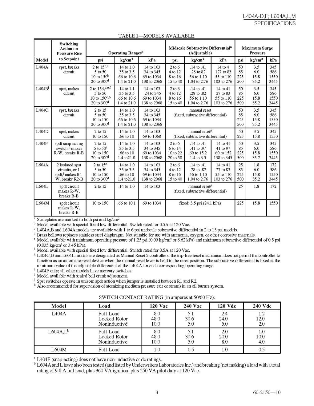
11 TRIAD MODULAR STEAM BOILERS Series 300 fires at MBH Series 600 fires at MBH Series 900 fires at MBH Series 1600 fires at MBH Series 200 fires up to 2000MBH STANDARD COMPONENTS: Series Number X4-400 Powerflame Gas Burner X X4-700 Powerflame Gas Burner X JR30A Powerflame Gas Burner X JR50A Powerflame Gas Burner X Other Components L404F1060 Pressuretrol operating (LP) X X X X L4079B1033 Pressuretrol safety (LP) X X X X Operating Light X X X X *P7810C Solid State/multi function pressure/mod control with operating light Pressure Gauge X X X X Pressure Relief Valve X X X X 150 Water Level Control X X X X 750-MT-120 Low Water Cut-Off X X X X Manual reset Gauge Glass Assembly X X X X R845A Control Center X X X X 1 ¼ Ball Valve and fittings for blow down X X X *All low pressure steam boilers come standard with the L404F1060 & L4079B1033 controls. The P7810C is standard on high pressure steam boilers and when low pressure steam boilers have modulation added to them. OPTIONAL COMPONENTS: Barometric Dampers: MG1-8" RC-6" Burners: Series 300: Oil Fired (Riello) Series 900 or 1600: Spark Ignition System Oil-Fired: CR1-O Low Nox - NPM 30 or NPM 50 Combustion Intake flange CSD-1 IRI Gas Train Modulating Gas Train Cleanout Openings: CLNOUT 22 CLNOUT 44 Fan/Damper Relay FDR For Gas or Gas/Oil, Field Mounted. For Oil-fired 300 model Boiler only, Field Mounted. Natural Gas or #2 Oil (Requires Gas Pilot For Firing). GPDS Spark Ignition For No. 2 Oil. Low Nox natural gas burner For Sealed Combustion/Side-Wall Venting. For Power Flame Dual Fuel Burners, standard on all others. Motorized Gas Valves, Alarm Bell. Motorized Gas Valves. 2 Nipples and Caps installed top-front only 4 Nipples and Caps. MODEL INFORMATION SECTION II
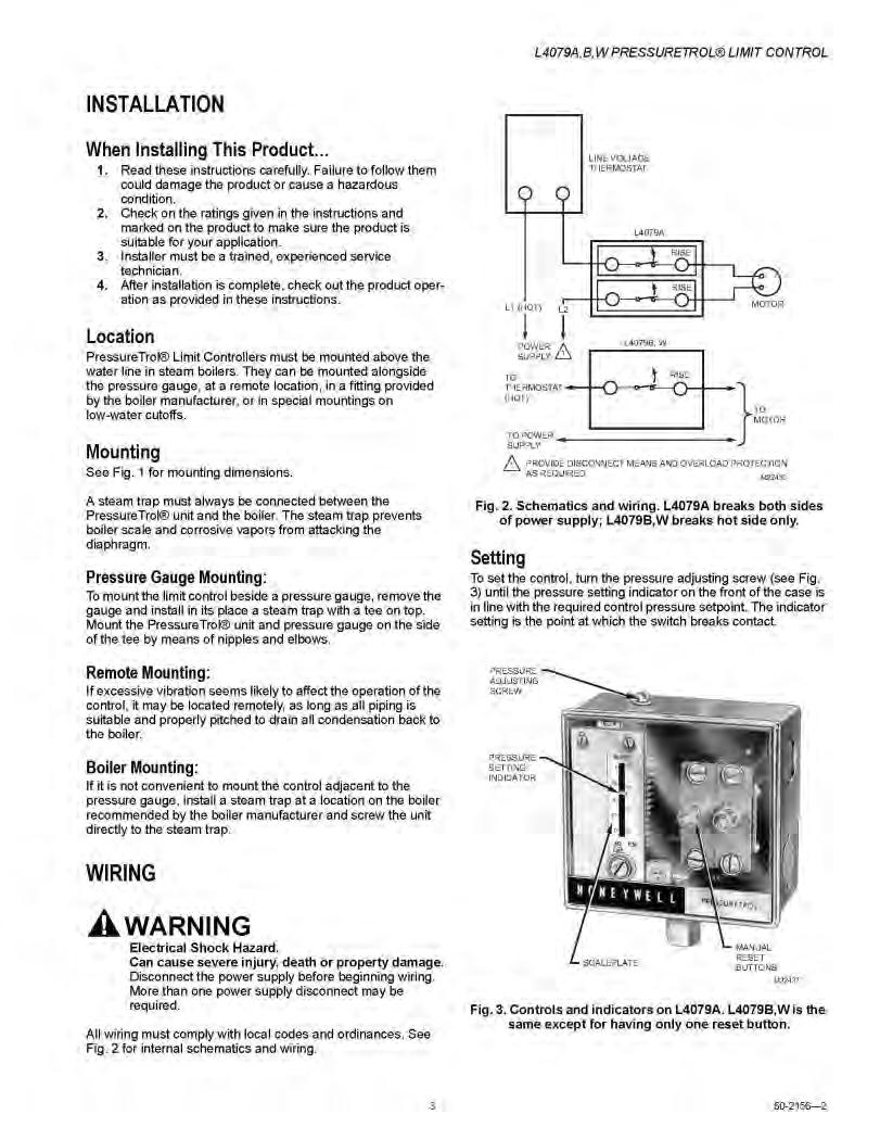
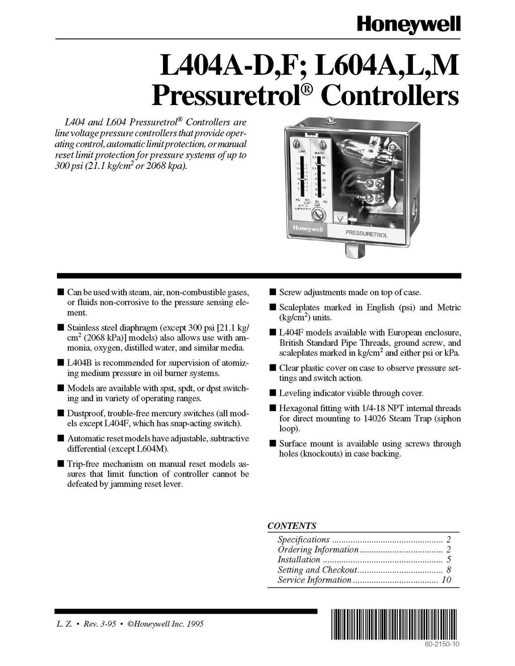
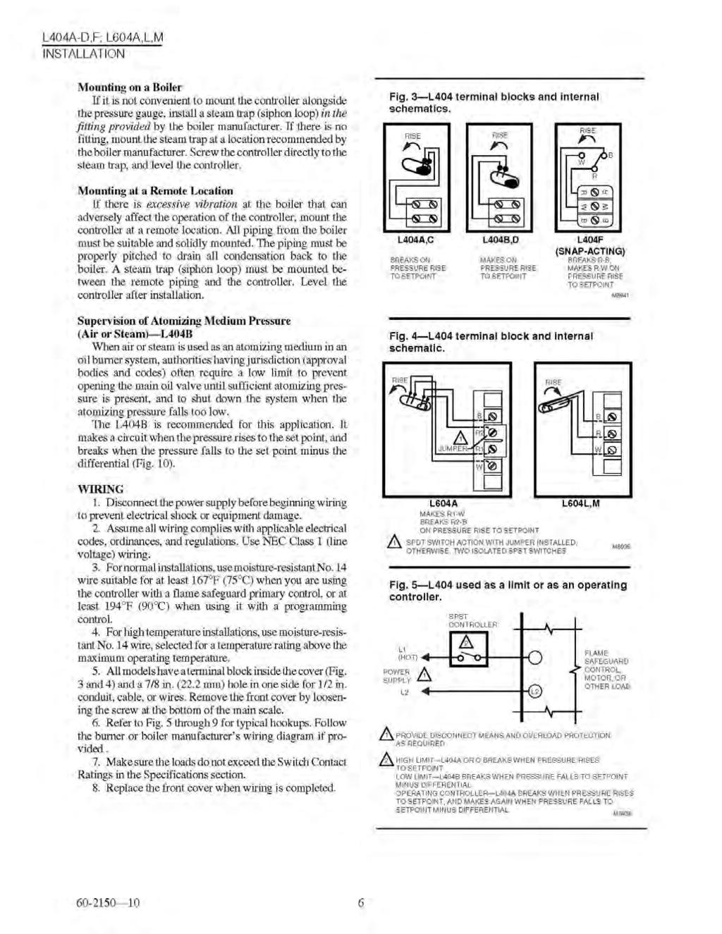
12 SUPERIOR BOILER TECHNOLOGIES Section III STEAM BOILER SYSTEM COMPONENTS TRIAD boilers are designed to very strict standards; certified to meet and exceed American Society of Mechanical Engineers (ASME) codes; and registered with the National Board of Boilers and Pressure Vessel Inspectors (NBBI). TRIAD uses only UL listed controls and UL listed burners and gas trains. Every boiler is a Category I non-condensing gas appliance. TYPICAL BURNERS Series 300: Power Burners Gas Power Flame X4-400 or Riello G400 Straight Oil Riello F10 Series 600: Gas Series 900: Gas Oil or Dual Power Flame X4-700 or Riello G750 Power Flame JR30 or Riello RS 28 Power Flame CR1 or Riello RLS28 Low Nox Power Flame NPM 30 Series 1600 & 2000: Gas Power Flame JR50 Oil or Dual Power Flame CR2 or Riello RLS 38 Low Nox Power Flame NPM 50 ELECTRICAL Standard volts, 60 Hz, single phase Series amps per boiler Series 600, 900 and amps per boiler CAUTION Some local codes require a master power off switch for boiler room equipment and may specify its location. Electrical service and connections must meet all applicable codes. INDIVIDUAL BOILER CONTROLS Individual component product information is included in Section VI. The configuration for your specific boilers is shown in Section II. Burner manuals are sent with the burner. SYSTEM COMPONENTS ELECTRICAL WIRING BOX The electrical box with a screw-on cover contains various electrical wiring components for each boiler - ON/OFF switch; fuses, terminals and relays for fan damper control, lockout control, etc. The boiler limit control circuit starts & ends in this box. Field wiring connections for line voltage service power and low voltage (TT) thermostat/control are provided in this box via clearly marked, screw-in terminals. R845A - CONTROL CENTER Used on Steam boilers in conjunction with Low Water Cut-offs (LWCO) and pressure controls to manage the overall operation of the boiler, cycle the burner and illuminates the Call For Heat light. The R845A control is activated by closing the circuit between the two low voltage terminals (T-T) via a 24 vac 2-wire thermostat or a control panel otherwise known as a Call For Heat. The R845A control is wired in series with the Low Water Cut-off controls (LWCO) and the Pressuretrols and will activate the boiler control circuit only if a low water condition does not exist and the high pressure limit has not been exceeded. L404F1060 Operating Pressure On/Off Control This line voltage, pressure-sensing switch has an adjustable differential and automatic reset. When boiler steam pressure rises past the control set point, the switch opens, stopping the burner operation. When the boiler pressure falls to the set point minus differential, the switch closes to restart the burner. L4079B1033 Safety Pressure High Limit Control with Manual Reset. This is a line voltage, steam pressure sensing switch with a manual reset trip function. When the boiler s steam pressure rises above the set point of the SECTION III
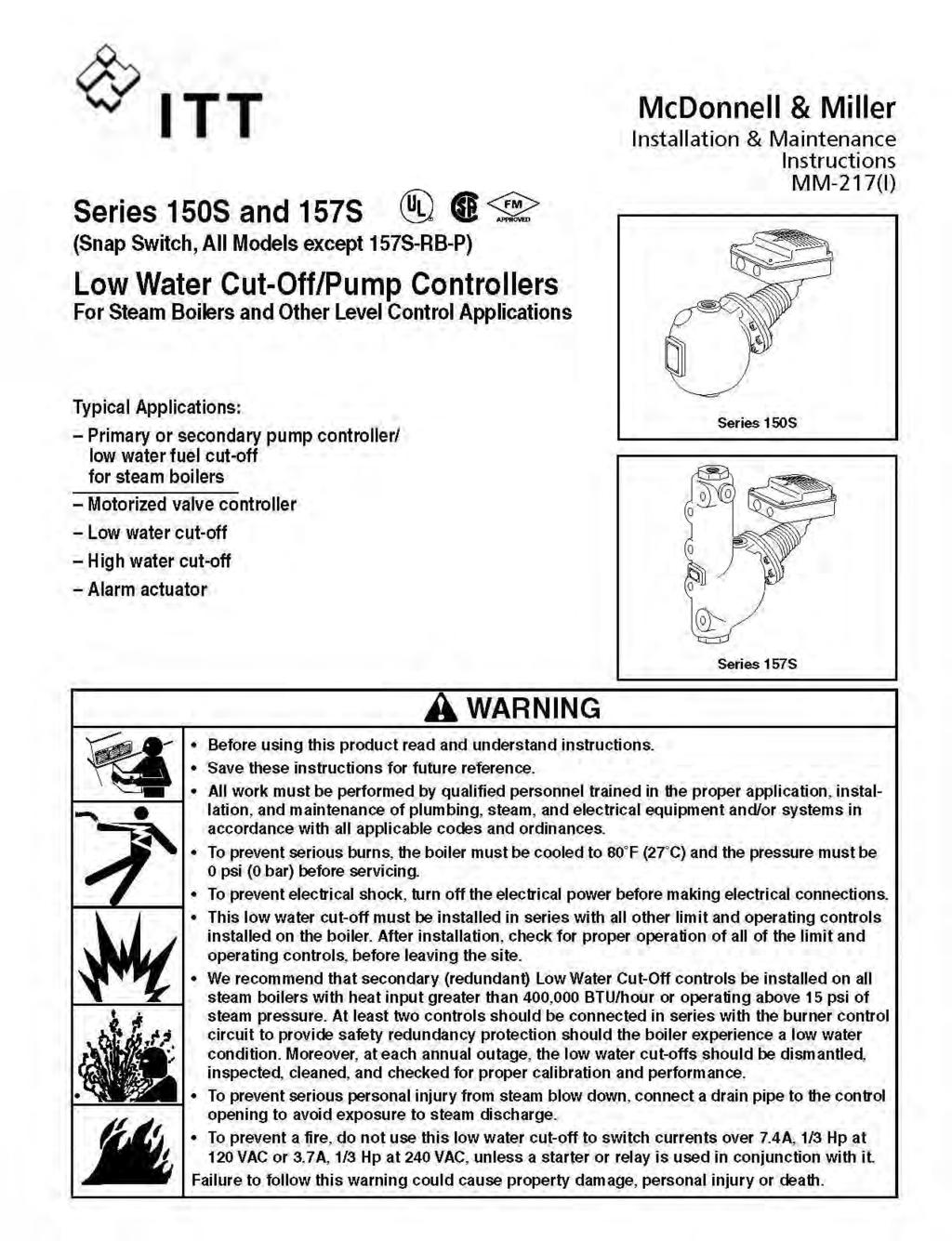
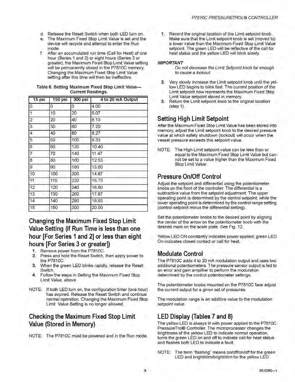
13 control, its switch opens and the manual reset trips to shut down burner operation. If the manual reset is tripped OPEN then a serious problem exists with your boiler. The boiler should not be put back into service until the problem has been identified and corrected P7810C Operating Pressure On/Off Control and Safety Pressure High Limit Control with Manual Reset. The P7810C is a line voltage control that performs the same functions as the L404F1060 and L4079B1033 but in one control. The P7810C also has a 4-20mA modulating signal. For On/Off Control, it uses a separate integral electronic pressure sensor with an adjustable set point, an adjustable differential and automatic reset. When boiler steam pressure rises past the control set point, the switch opens, stopping the burner operation. When the boiler pressure falls to the set point minus differential, the switch closes to restart the burner. For High Limit Control, it uses a different and separate integral electronic pressure sensor with an adjustable set point and has a manual reset trip function. When the steam pressure rises past the control set point, the switch opens and the manual reset trips, which shuts down the operation of the burner. When the boiler pressure falls below the set point, the burner will not restart operation until this control has been reset manually. If the manual reset is tripped OPEN then a serious problem exists with your boiler. The boiler should not be put back into service until the problem has been identified and corrected If less than 2 psi operating pressure is required the P7810C is not the best choice, instead you should revert to the standard L404F and L4079 operating controls. 150 SMD - LOW WATER CUT OFF (LWCO) This two-stage control senses the water level within the vessel shell to switch the power for both the feedwater solenoid and the burner. When the water level has dropped approximately ¾ of an inch below the nominal operating water level (about 2 to 3 gallons), the first stage switch closes providing line voltage to the boiler feedwater solenoid. This circuit will remain powered until the water level returns to normal. If the water level continues to fall, the second stage switch opens which stops the burner operation. The burner switch will be closed once the necessary feedwater has been provided to the boiler. NEVER "dry fire" (operate a boiler with insufficient water). It is an extremely destructive and a dangerous practice. 750-MT-120 SAFETY LOW WATER CUT OFF WITH MANUAL RESET This control senses the water level within the vessel shell to shut down the burner in a low water condition. If the vessel water level drops below the minimum, the control switch opens, tripping the manual reset and stopping the operation of the burner. This control requires a manual reset. If the manual reset is tripped OPEN then a serious problem exists with your boiler. The boiler should not be put back into service until the problem has been identified and corrected. NEVER "dry fire" (operate a boiler with insufficient water) It is an extremely destructive and dangerous practice. 67M SAFETY LOW WATER CUT OFF (LWCO) with MANUAL RESET LOW PRESSURE STEAM This control is used on older Low Pressure Steam boilers (15 lbs) built prior to 2011 and senses the water level within the vessel shell to shut down the burner in a low water condition. If the vessel water level drops below the minimum, the control switch opens, tripping the manual reset and stopping the operation of the burner. This control requires a manual reset. If the manual reset is tripped OPEN then a serious problem exists with your boiler. The boiler should not be put back into service until the problem has been identified and corrected NEVER "dry fire" (operate a boiler with insufficient water) It is an extremely destructive and dangerous practice. ON/OFF SWITCH & FUSES The ON/OFF switch and dual fuses provide a safe way of removing power from the boiler. NOTE: Replace fuses only with the same type as specified inside the wiring box cover and then only after determining why the fuse(s) blew. SYSTEM COMPONENTS SECTION III
14 RELIEF VALVE The relief valve should NEVER function under normal operations. If it has then something needs to be adjusted. Many codes require periodic testing and replacement of relief valves -- the user must meet local code requirements. Many codes require that the safety relief valve be freely vented to the outside atmosphere (potential line freezing must be considered). Relief valves are sized for both their pressure rating and their BTU/hr load. Replace only with properly sized, ASME approved units designed for steam systems -- SEE MANUFACTURER'S TAG ATTACHED TO THE VALVE. PRESSURE GAUGE Indicates boiler vessel operating pressure. LIFTING LUGS (optional on 300 series) Lifting point of boiler for ease of installation. FAN DAMPER RELAY (optional) SQUARE D 8501 DPDT with line voltage coil BAROMETRIC DAMPER (optional) FIELD MG1-8, RC-6 TRIAD recommends one barometric damper be installed for each boiler or at least one be installed in the breeching between the first boiler and the stack. Steam Header Connects to near boiler piping. The header then transfers steam to heating zones. Header MUST always be a minimum of 24 above the top of the boiler this helps to ensure dry steam production. Air Separation System -- Removes dissolved gases from recirculating system water, which TRIAD highly recommends for open systems. Water Treatment System -- Helps ensure water quality and control of ph, hardness and dissolved materials. Vent and Expansion System Typically part of the boiler feed water and condensate return system. Water Pressure Reducing Valve -- Drops supply water to system pressure and maintains a minimum (18 psig) pressure within the system. Gas Line Pressure Valve -- Lowers supply gas pressure to gas train range (typically less than 14" WC psi). Oil Supply System -- Allows single or two line transfer of fuel oil from the supply tank to the burner train. Thermostat Control -- Varies between a simple two wire thermostat to a microprocessor outdoor reset control panel. Some applications may use a remote application sensor that closes the boiler thermostat Call For Heat control circuit. OPERATING LIGHT Call For Heat indicator mounted on Boiler Control Center. This is integral to the P7810C control. CLEAN-OUT OPENINGS (Optional) Nipples and caps are for easier inspection and boiler vessel service. OTHER SYSTEM COMPONENTS In addition to the boiler and burner, a complete heating system may include the following: Near Boiler Piping field installed piping that connects the boiler to the main steam header. Typically incorporates a Hartford loop. The separation between the equalizer and the condensate return loop should always be kept to a minimum; use a close nipple whenever possible. SYSTEM COMPONENTS SECTION III
15 SUPERIOR BOILER TECHNOLOGIES Section IV GENERAL OPERATIONS Prior to starting your boiler system, please familiarize yourself with each boiler control by reviewing both Sections lll and VI or this manual TRIAD steam boilers may be used in many different applications. The boiler is designed to convert water to steam under controlled pressure. The amount of steam produced is in direct proportion to the BTU/hr (British Thermal Units per hour) rating of the burner. The steam temperature and the pressure pounds per square inch gauge (typically referred to as psi) are always directly related. For example, in a typical space heating application, a boiler fired at 900MBH/hr will produce up to 749 pounds of steam per hour. The same boiler firing at 600MBH/hr would produce approximately 512 pounds of steam per hour. The difference between the two examples is the firing rate of the burner and thus the heat produced. In either case, the steam pressure and temperature would be the same - the volume of steam produced would be different. Since virtually all of the thermal output is carried as latent heat (heat required to convert water to steam) the heat transfer is not controlled by the steam pressure. It is imperative that the initial setting for each control (i.e. Operating Pressure Limit, Safety Pressure High Limit, etc.) be made before attempting to start up any boiler All TRIAD Steam boilers are equipped with a Control Center; two low water cutoff (LWCO) controls - one with a manual reset and dual pressure limit controls - one with a manual reset. Other controls may be installed as add-on options Unless otherwise noted, all control circuits and wiring connections are line voltage. The R845A Control Center requires a Call For Heat to activate it. This is accomplished by closing the circuit between the two low voltage terminals (T- T) via a 24 vac 2-wire thermostat; an outdoor reset control panel; or a simple temperature control. Power is supplied to the boiler by setting the ON/OFF switch to the ON position. With this switch in the ON position, all of the controls on the boiler are live and great caution must be taken before touching any wiring. Turning the ON/OFF switch to OFF means only that the power to the boiler mounted controls is off. NOTE: Power to controls and systems not mounted on the boiler (fan dampers, induced draft fans, etc.) is not provided by the boiler controls even though these off boiler systems may be activated by boiler mounted relays, etc. Extreme caution must be taken before attempting to service any off-boiler systems as there may still be electricity present in them even with the boiler ON/OFF switch in the OFF position. NORMAL Operating Conditions are when the vessel steam pressure is not above the operating high limit - see L404F1060 or P7810C Pressuretrol Control and a low water condition do not exist - see LWCO controls. ABNORMAL Operating Conditions would include but not be limited to: electrical failure; fuel interruptions; vessel steam pressure that exceeds the control set points, a low water condition; a malfunctioning control; etc. Specific wiring diagrams for your boiler system are included in Section ll of this manual. Descriptions of controls and their operations are generic. See Section VI of this manual for the manufacturer s instructions. Specifications and configurations are subject to change without notice. ALL STEAM MODELS These single function boilers provide low pressure steam max 15 psi or high pressure steam max 150 psi. SETTINGS Nominal system design pressure is established by the pipe size chosen by the design engineer. Once the initial setting is established, adjustment may be required based on system performance and design criteria. GENERAL OPERATIONS SECTION IV
16 Operating Pressure Limit Control (L404F1060) Typical operating pressure for a low pressure heating application is 3 to 5 psi - plus/minus 1 to 2 psi. Other applications may be quite a bit higher. Safety Pressure High Limit Control - Manual Reset L4079B1033 or P7810C. Nominal operating pressure that is set as the Operating Pressure Limit (above) plus 2 to 3 psi. OPERATION Under Normal Operating Conditions a Call For Heat to the R845A Control Center would activate the burner control circuit that starts the burner ignition cycle (see burner manufacturer s instruction manual) and illuminates the operating light on top of the control or in the P7810C. The heat applied to the vessel water increases the vessel water temperature to boiling converting the water to steam. As the water is steamed-off, makeup water must then be supplied by the boiler feedwater make-up system. Boiler Feed Water Control (150BMD) -: A float in this control senses when the actual water level in the boiler reaches 3/4 below the normal water level of the vessel and closes a contact to provide power to the field installed, normally closed, feedwater solenoid. When powered, this solenoid opens to provide make-up water to the boiler until the float senses that the water level in the boiler has reached its nominal level again at which time power is cutoff to the solenoid which then closes, stopping the flow of make-up water. This cycle will repeat as the boiler water level rises and falls during the normal operation of making steam. above the setting of the Operating Pressure On/Off Control - L404F1060 or P7810C, which will open the contacts in the control stopping the burner from firing. Once the vessel pressure drops below the differential set point in this control, the contacts in the control will close and the burner ignition will start again. Typically this condition may occur when the system is approaching dynamic balance near the nominal system operating temperature -- the entire output for the boiler exceeds the current system needs. It may also occur if - the boiler sequencing is too aggressive or the boiler has been oversized for the system. NOTE 2 - If the manual reset circuit of the Safety Pressure High Limit Control - L4079B1033 or P7810C - is tripped - this indicates a serious problem with your boiler. It is mandatory that the boiler be immediately removed from service and the cause identified and corrected. It is possible that the other high limit pressure control was set wrong or has malfunctioned (very serious condition). One or both controls may need to be replaced. The system may have to be inspected before the boiler is returned to operation.. NOTE 3 - Low Water Cut-Offs (LWCO) limits are not adjustable - their control limits are fixed. If the manual reset circuit of the LWCO - (67M) has tripped, this indicates a serious problem with your boiler. It is mandatory that the boiler is removed from service and the problem be identified and corrected. It is likely that the other LWCO (150BMD) has malfunctioned (very serious). One or both controls may need to be replaced. The boiler will continue to operate until the Call For Heat is satisfied and the control is deactivated by opening the circuit (T-T) OR an ABNORMAL Operating Condition has developed. Multiple Boiler Setup It is highly recommended to use a panel to control multiple boilers. They should be operated in a Parallel Manner (meaning all boilers should fire at same time.) Bring the boilers up gradually, starting on low fire, and once the desired system pressure is reached, then drop the individual units off maintaining system pressure with a minimal number of units. Do not try to reach system pressure by firing one boiler up to high fire, then firing another up to high fire, etc. When dealing with steam, it is much better to bring the entire system on gradually, then drop off units as they are not needed. NOTE 1 - At times the boiler pressure may rise GENERAL OPERATIONS SECTION IV
17 SUPERIOR BOILER TECHNOLOGIES Section V INSTALLATION & STARTUP INSTRUCTIONS A. UNPACKING STOP: Before proceeding with this section, carefully read the other Sections in this manual. Always protect boilers from the weather. All cartons and crates should immediately be inspected for any damage. If any damage is found at the time of delivery, proper notation should be made on the carrier's Bill of Lading before signing for delivery. Damage claims should be filed immediately with the carrier. Claims of shortages should be filed in writing with Superior Boiler Technologies within five (5) days of receipt. For those boilers with leveling legs, the boiler is shipped with leveling bolts to be field installed into the leveling legs.. The burner carton contains the manufacturer's instruction manual and gas train components. The wiring diagram(s) for the boiler are included in this manual and copies are included in the electrical wiring box. Suggested near boiler piping diagrams are available in TRIAD s Boiler Manual. The boiler tags should be checked to confirm the boiler model, the serial number the burner model and burner rating. These should agree with the information shown on the Packing Slip found in Section II of this manual. B. WHERE TO LOCATE Boilers must be protected from weather and should not be exposed to potentially freezing temperatures. Boilers should be located as near as possible to the stack of the breeching system. Consideration should be given to water drainage for the relief valve and LWCO s and access for boiler service. Install the boiler only on a level, non-combustible surface and level it with the leveling bolts provided. Sufficient clearance is required for operation and service. Suggested minimum clearances for service access are: 48 in the front; 18 for the sides and rear; and 24 up to the breeching and header connections. However, clearances on sides and rear for boilers above 50 PSIG are 36. The near boiler piping and the rise to the header are particularly important for proper boiler operation. Do not reduce the size of the steam supply opening. Ensure that the near boiler piping is as specified by Triad / Superior and the design engineer. The rise in the connector from the boiler to the breeching system can be its most effective part. Generally, the longer the rise, the better the draft. A draft hood or barometric damper for each boiler is generally recommended. At a minimum, one damper should be located in the breeching between the first boiler and the stack. Additional information is available in the TRIAD Boiler Manual. Also, the installation must comply with local codes. Adequate combustion air must be provided to the boiler room. Provisions must be made for adequate water supply and treatment - the condensate return/makeup water/boiler feed system. When using multiple boilers, Triad highly recommends having a permanently pressurized feedwater loop with fast opening ASCO valves so that water is feed into boilers in a timely manner. Fuel supply and electrical service must be provided. Typically, burner startup service will be required. C. INSTALLATION WARNINGS/CAUTIONS CAUTION: Before connecting the fuel supply and burner, be sure to read the burner manufacturer's manual. WARNING: BEFORE ATTEMPTING ANY ELECTRICAL SERVICE, DISCONNECT POWER FROM THE BOILER. 1. TRIAD does not design boiler rooms. TRIAD recommends that a competent system design INSTALLATION SECTION V
18 engineer be retained to design the heating system, supervise the installation and oversee the startup 2. Only a qualified individual such as a licensed electrician should attempt to service electrical or control circuits. Only a qualified HVAC technician should attempt to service or to start up a burner.. 3. The installation must conform to the local codes having jurisdiction over your area and this type of equipment. Without local codes, refer to the National Fuel Gas Code. At a minimum BOCA code compliance must be met. Where required the American Society of Mechanical Engineers (ASME) Safety Code for Controls and Safety Devices for Automatically fired Boilers (CSD- 1) must be met. User insurance requirements may be a factor in the installation requirements. Connections to water, breeching and electrical service must meet all applicable codes. These may include but are not necessarily limited to the National Electrical Code, BOCA standards on Combustion Air and local water, power and fuel supplier requirements. On-site inspection by local, state or third party insurance agents may be required before placing the system in operation. 4. TRIAD recommends that a MASTER POWER DISCONNECT SWITCH AND A FUEL SYSTEM CUT OFF VALVE be installed for each boiler room. 5. NEVER "dry fire" a boiler - operate the burner without full and sufficient water in the boiler. Verify that the combustion air, breeching, venting, fuel supply, water supply, boiler feed and makeup system, and the condensate tank(s) have been properly installed before attempting to fire the burner. Burner startup procedures are found in the respective burner manufacturer's instruction book. Be sure to read, understand and heed all warnings. Improperly installed or maintained boiler systems can cause high levels of Carbon Monoxide, risk of boiler damage or personal injury. D. INSTALLATION FIRST, THE BOILERS 1. TRIAD recommends that all water connections be completed prior to the connection of fuel and electrical power. This will help ensure that a dry fire situation is avoided and reduce the possibility of spraying water over live electrical components. All fittings should be tight and an appropriate sealant INSTALLATION (pipe dope) applied. 2. The safety relief valve should be plumbed in accordance local code and compliant with the manufacturer's recommendations. See the tag attached to the relief valve. The valve should be installed in a vertical upright position with no unnecessary intervening pipe. Under no circumstances should there be a shut off valve or restriction of any kind between the safety valve and the connection. Do not cap or plug the drain hole in the valve body. Many codes require discharging to the outside atmosphere. Use discharge pipe of size equal or larger than the valve outlet. Use schedule 40 discharge pipe, not schedule 80 nor extra strong pipe to avoid undue stress on the valve. It must allow for easy draining of condensate at or near the valve outlet and must terminate freely to the atmosphere. 3. The LWCO s should be plumbed according to local code and the manufacturer s instructions. Typically the discharge lines must not be restricted or downsized; and should be aimed to reduce the potential exposure of steam and hot water release. The ends of the discharge lines should have no fitting. The relief valve line should be left clearly visible so that if it should operate it will be evident that a discharge has occurred. 4. Flush, connect and test all system water lines. 5. Fill the boiler(s) and verify that the boiler water level is met and there are no leaks in the system. 4. Verify that the water treatment, boiler feed, makeup and condensate systems are properly set to the manufacturers and system design engineer's requirements. E. NEXT - THE FUEL DELIVERY SYSTEM Specific limits and procedures covering fuel line installation, piping, and pressure and leak detection are important to review and understand. Generally, gas burners should not receive over 0.5 psi (14 inches water column) of gas supply pressure from lines of sufficient volume to avoid an undue pressure drop (see the burner manufacturer's manual). This typically requires the installation of a gas line pressure regulator before the gas train. Oil supply systems may be one or two line type depending on the burner and system design. SECTION V
19 LP systems require pressure regulators and LP specific burners. Use extreme caution while working on fuel lines to avoid ignition sources. Fuel lines should be checked with an appropriate leak detection fluid or procedure. Many fuel supply companies can provide assistance with appliance connections Ensure that the fuel supply is shut off at its source before performing any work on the delivery system. F. NEXT - THE BURNER The burner should not be connected to the fuel supply line until all testing and leak detection of the fuel delivery system is completed STOP: The burner connections warrant special attention. Verify that the recommendations and warnings in the OEM s burner manual are followed. 1. Verify that the fuel supply is shut off at its source. 2. Verify that the firebox is clear of all foreign material or fuel and that the refractory is intact 3. Mount the burner on the adapter plate supplied with the boiler using the gasket or insulating rope supplied with the burner. 4. Connect the wiring harness to the burner contacts as shown on the wiring diagrams included with the boiler and in this manual. 5. Connect the fuel source to the burner. 6. The burner must be properly adjusted and set up for each site before operation. All burners use both automatic pilot ignition and some form of flame detection. NEVER try to manually light a burner. 7. Make sure all fuel feed valves remain closed. For proper combustion is it critical to have sufficient fresh air for the burner. Make sure there is at least one square inch of opening of fresh air for every 3,000 Btu input. For proper ventilation install two fresh air openings, one 24 from the floor and one at a high level to make sure hot air is exhausted from the boiler room. Do not install any exhaust fans in the boiler room, this can starve the boilers of air resulting in poor combustion, and create a downdraft in the stack. G. NEXT - ELECTRICAL CONNECTIONS FIRST Verify that the line voltage power is off and the Call For Heat control (thermostat) is off. 1. Connect the line voltage service to L1 and L2 terminals in the electrical wiring box on the boiler. 2. Connect the low voltage (thermostat) circuit to the T1 terminals in the wiring box on the boiler. H. FEEDWATER PIPING Feedwater piping is important to provide adequate water supply with properly sized piping. Make sure you follow proper local code requirements. Use the following diameters for the appropriate boiler. MBH Input HP Inches ¾ ½ Make sure pipe is supported near the pump and is not using the pump as its means of support. Make sure the city water pressure in not above 40 psi when feeding the boiler using a return system. The follow chart shows the steaming rates for Triad boilers. On the next page is a chart showing the steaming rates for the Triad boiler models. When using multiple boilers in a modular setup, Superior highly recommends having a permanently pressurized feedwater loop with fast opening ASCO valves so that water is fed into the boilers in a timely manner. Also shown on following pages is recommended near-boiler piping for the 900 and If a direct sidewall connection to bring in outside combustion air is installed, make sure the vent is designed for a pressure drop of no greater than.10 wc. So be aware of length, diameter and elbows. INSTALLATION SECTION V
20 Recommended Near-Boiler Piping Series 900 Low Pressure Steam Series 1600 Low Pressure Steam INSTALLATION SECTION V
21 Feedwater Information Steaming Rates and Loop Characteristics SERIES 300 SERIES 600 SERIES 900 SERIES 1600 Firing rate 375 MBH 600 MBH 1000 MBH 1700 MBH Steam pounds/hr produced Make-up Water Required (gallons per refill): Steaming Rate before refill starts: 93 seconds 100 seconds 61 seconds 54 seconds Loop Characteristics (typical): - constantly under pressure 20psi 20psi 20psi 20psi - solenoid valves control feed to each boiler Refill Cycle Time seconds based on loop characteristics 9.5 seconds seconds seconds seconds Solenoid Valve: (typical with ethylene propylene discs) 8220G5 ASCO 3/4 8220G7 ASCO G7 ASCO G7 ASCO 1.0 The Pressurized Loop mentioned above is most important when setting up a modular steam plant of several boilers to ensure that feedwater/condensate is delivered to the boilers in a timely manner. INSTALLATION SECTION V
22 I. IMMEDIATELY PRIOR TO STARTUP Verify that: - The breeching has no leaks. - The combustion air requirements are met. - No combustibles or vapors are present in the boiler room area. - All ventilation and combustion air openings and louvers are clean and free of debris - All stack and breeching dampers are set. - All flue and breeching passages are clear of any fuel accumulations. - Test the safety relief valve. - Test the LWCO. ( blow down ) valves. - Confirm that the system design engineer has completed all mandatory code installation requirements including necessary inspections. - Verify that air separation, water treatment, boiler feed, makeup water and condensate return loop components are operating correctly as per manufacturers' instructions. - Verify that all operating controls are set. - Verify that all safety controls are set. - Verify that the burner pre-purge cycle, ignition and ignition confirmation circuits are functional before opening fuel feed valves. J. START UP After all system and pre-start checks have been completed, apply fuel, power and control signals as directed in the burner manufacture's manual. K. IMMEDIATELY AFTER FIRING: Monitor the first ignition cycle carefully for proper operation Continue to monitor initial operations and adjust the burner as required for correct operation. Note the combustion products readings for future performance monitoring and ensure operations are on the correct side of the curve - excess oxygen. INSTALLATION Continue with a normal shutdown. Observe the burner for correct response and physically inspect the burner and firebox sight glass to ensure that the flame has been completely cut off. Closely monitor several complete cycles to confirm proper operation. Ensure that all of the steps in the burner manufacturer's instructions have been completed. Complete Operator training. Begin keeping a Maintenance Log -- record all startup readings. Balance the system to the design engineer's specifications by adjusting flow, control, and temperature settings. Some "trial and error" is inevitable. Section IV covers typical boiler operating sequences and controls. Section VII covers Maintenance and Section VIII Troubleshooting (for qualified technical support only). CLEANING THE BOILER (BOIL OUT/SKIMMING) New steam boilers need to be thoroughly cleaned before being placed into normal operations. After installation and before the boiler is officially in service the pressure vessel should be cleaned of any oil film, dirt, and other impurities. The boiler should be ready for firing and the operator should be fully familiar with the operation of the boiler and burner and follow instructions contained in those manuals. The operating conditions of all auxiliary equipment should be formally checked out. Boil outs and skimming the water surface are methods of cleaning a steam boiler and the system to remove oils and contaminates from the water. It is performed by heating the boiler to temperature and then skimming off the top of the water at the water line. New boilers require repetitive cleaning during the first few weeks of continuous operation. Existing boilers need cleaning whenever the water level begins to surge, prime or bubble. The gauge glass should be dry above the water line and the water line should be stable. Changes in the gauge glass water level or the presence of visible moisture above the water line or water droplets carrying over from the top suggest the need for a good cleaning. It is usually best to let the boiler operate for several days to clear out the system before doing the initial SECTION V
23 cleaning operation. See section VII. The manual blow-down valves on the LWCO controls should be operated at least 2 to 3 times a day during the first two weeks of boiler operation. After that, manual blow-down should be performed at least daily on all operating boilers see LWCO manufacturer s instructions and Section VII. The skim tapping (flange) on the rear of the boiler should be piped with a shut-off valve and discharge line to a suitable drain (local code permitting). level, typically visible through the gauge glass. You can also refer to the instructions in Section 7 of the ASME Boiler Code for more detail on cleaning pressure vessels. Depending on the age and condition of the system, the system may require several cleaning cycles Three possible methods are suggested depending on the conditions, age and size of the systems.. 1. The simplest method is to run the system and dispose all condensate for several days until it runs clear (if allowed by local code). This method is the least effective. 2. Another method, which is more effective is the following: A) Run the boiler to a low boil temperature - slightly above 217 F or 2 psig. Then turn the burner off. B) Isolate the boiler from the rest of the system and allow the boiler to cool until no pressure is showing on the gauge. C) Open the skim tap shut-off valve carefully to skim off the top level of water be careful of flash. Power the boiler feed water solenoid open to replace the water being skimmed-off D) Capture a sample of the spill into a suitable container about 2 inches across and 9 inches deep and heat it to a boil. If the water foams, surges or forms large bubbles, then dirt and oil remain in the system. 3. A third method is chemical cleaning, which is the most effective method. There are special trademarked chemicals available on the market for boil outs. It is strongly recommended that a water treatment consultant with expertise in boiler water chemistry be available to provide direction as required. Failure to completely clean a new boiler will result in wet steam production and erratic boiler performance. The oil in the water will lead to foaming, and surges ( priming ) in the water INSTALLATION SECTION V
24 SUPERIOR BOILER TECHNOLOGIES Section VI OEM COMPONENT PRODUCT DATA It is imperative that the documentation in this section be thoroughly reviewed before placing the boiler in operation. These materials include specific operating warnings that must be followed for proper boiler operations. Failure to follow the directions and warnings can result in serious personal injury and/or damage to the boilers and other property. IMPORTANT: It is important to pay special attention to the burner manufacturers Installation and Operation Manual. OEM COMPONENT DATA
25

26
27
28
29
30
31
32
33
34
35
36

37
38
39
40
41
42

43
44
45

46

47

48

49

50

51

52
53

54
55
56

57

58
59
60
61
62
63
64

65
66
67 Superior Boiler Technologies Section VII GENERAL MAINTENANCE CAUTION: Start with a review of the warnings, cautions, notes and NBBI recommendations found in Section I of this manual. Maintain a clean boiler room. Provide clean water to the boiler. Maintain a planned program of proactive preventive maintenance. WARNING: NEVER "dry fire" the boiler - operate the boiler and burner without the boiler being completely filled with water. NEVER operate the boiler without a functional Low Water Cut Off control. NEVER operate the boiler without a functional High Pressure Limit control. NEVER reset a tripped manual shutoff without first removing the boiler from service, determining the cause of the problem and correcting the cause. WARNING: NEVER operate the boiler without an ASME approved, steam rated safety relief valve matched for both BTU/hr and pressure relief values. Test and inspect the relief valve at least annually. Replace defective valves immediately or as required by code. See Safety Relief Valve manufacturer's tag. NEVER operate a boiler if the safety relief valve has discharged. If the safety relief valve has discharged, something is wrong. Immediately remove the boiler from service and have a trained service technician investigate and correct the problem. Warning: Blow-down flush the Low Water Cut Off controls at least daily during service periods. Failure to thoroughly flush the controls can render them inoperative. MAINTENANCE If the burner continues to operate during a blowdown, the boiler needs to be removed from service and the controls inspected immediately. NEVER add water to an overheated boiler. This can cause an immediate conversion of the water to steam with an explosive increase in volume. Turn OFF the burner and allow the boiler to cool slowly. NEVER fire a boiler without the turbulators installed in the fire tubes. NEVER fire the boiler if the firebox or tubes have excessive buildup or there appears to be signs of water leakage in the combustion chamber.. NEVER bypass any of the controls on the boiler, fuel train or burner. If a control is considered defective, replace it before using the boiler/burner again. NEVER fire a boiler above its rated input. NEVER allow a boiler to be exposed to freezing conditions. If used outdoors, properly protect the system from the weather. All TRIAD boilers are built to meet or exceed the Section IV ASME standard and are registered with the National Board to perform at a maximum of 15 psi (low-pressure steam) or a maximum of 150 psi (high-pressure steam). The boilers and their controls are designed only for heating water. NEVER expose a boiler to thermal shock. Thermally induced stress cycling can result in metal fatigue or failure. Maintain a minimum temperature differential between boiler feed water and vessel water. NEVER introduce "cold" water into a hot boiler. Boiler feed water should be a nominal 160 F before entering a hot boiler. Thermal shock voids the boiler warranty. In a steam system, good water quality and treatment are very important. The introduction of new water into a steam system also introduces oxygen (possibly with other dissolved gasses, minerals, particulates and organic material). This can cause internal corrosion, scaling and fouling material to I
68 build up in the boiler and system. Establish a suitable boiler water treatment program to reduce oxygen, scale, sludge buildup, corrosion and to control ph. Regularly verify that all ventilation, combustion air openings and louvers are clean and free of debris. OPERATORS & TRAINING Operators should be trained in and develop a thorough familiarity of the system and its controls. Operators should be trained in the use of fire prevention equipment. Operators should review and become familiar with all manuals, diagrams and warnings related to the system, the boiler and the burner. Written site procedures should be developed and be readily accessible to all operators. A permanent logbook should be maintained in the boiler room to record maintenance work, inspections, tests and other pertinent data. Only a qualified service technician should make burner or system adjustments and perform heating season start up. The boiler should normally operate on its own controls once it receives the "Call For Heat" signal. If the burner should fail to light after a Call For Heat, a system malfunction has probably occurred. A qualified service technician should determine the problem and correct it before putting the boiler back into service. PREVENTIVE MAINTENANCE SUMMARY NOTE: Read the tag attached to the Safety Relief Valve -- FOLLOW THE MANUFACTURER'S INSTRUCTIONS COVERING INSPECTION, TESTING, AND REPLACEMENT. WARNING: Protect yourself when testing Safety Relief Valves and performing blow-down of Low Water Cut-Off valves hot water and steam will flow from the drainpipes. If the burner does not shut-off during blow-down procedure, remove the boiler from service, determine the cause and correct it before returning this boiler to service.. Safety relief valves should be inspected and tested at the start of each service period and monthly during the service period. MAINTENANCE During the annual boiler inspection and cleaning, remove the valve and check for deposits in the valve and plumbing. If the valve has buildup, fails to operate or leaks, replace the valve only with an ASME approved steam relief valve of both the same pressure and BTU/hr rating. NEVER operate a boiler without a functional safety relief valve. Under normal service conditions, replace the valve every three to five years Blow-down valves should be inspected and tested at the beginning of each service period. Blow-downs should be performed at least daily during service period. See manufacturer s tag. The boiler room area should be kept as clean as possible and free of all debris. The boiler room should be thoroughly washed down at least weekly to eliminate all dust and dirt, which will help extend the intervals between boiler fireside cleanings.. WATER Properly treated vessel water is highly important, and critical for normal boiler service life and correct operation. Automatic feeding is highly recommended over periodic or slug / shot feeding. This is water free of excessive minerals and gases with a nominal ph of 7.8 ± 0.5. A ph reading of around 10.0 or higher can result in priming and surging, which can cause wet steam and/or flooding of the steam supply and steam header. A ph level only a single digit away from these recommendations can make a dramatic difference. This is because each increasing level of ph is ten times greater than the prior level. So for example, a ph of 8 is ten times more acidic than a ph of 9, and one hundred times more acidic that a ph of 10. Conversely, a ph of 8 is ten times more basic (alkaline) than ph of 7. Water Items Levels ph 7.5 to 9.5 TDS <2000 ppm Hardness CaCO3 (Calcium Carbonate) <10 ppm Alkalinity <300 ppm Organic Carbon No sheen or Foam (1) Iron Colorless Liquid (2) Suspended Solids No visual turbidity (3) (1) Organic Carbon After a water sample sits for 10 minutes there should be no visible solids. (2) Iron Hold a water sample against a white background and there should be no visible yellow, red, or orange tinge. (3) Suspended solids Vigorously shake a water sample for 30 seconds. There should be no visible sheen or foam. I
69 Water samples should be taken from the lower part of the boiler, not from an area higher up such as the gauge glass. Raw makeup water (feedwater) contains dissolved oxygen, suspended solids such as dirt, minerals and organic materials that can cause corrosive failure and a buildup of scale inside the boiler. One way to lower the amount of dissolved oxygen in feedwater is use a sparge tube. This injects steam into the feedwater to increase the temperature to 180 F to remove oxygen. Scale is a very effective insulator that will cause a loss of heat transfer efficiency and eventually tube sheet failure. Hard water results in a high amount of suspended solids. This condition is not covered under the boiler warranty. Water that is too soft can be even more aggressive, so a minimum hardness is usually recommended. And both soft and hard water conditions can result in boiler surging, which can produce wet steam. Too much oil present in the water will also cause foaming and surging. Other items that also are harmful to the boilers include silica, iron, chlorides, and phosphates. Following are several water treatment terminology items: Alkalinity Levels of this determine the ability of acids to be neutralized in water. Alkalinities can form carbon dioxide in steam, which is the primary culprit in corrosion in condensate lines. High alkalinity also causes foaming and carryover in boilers. High levels can be from infrequent blowdowns, or an overdose of alkaline water treatment chemical. Chlorides The higher the levels, the more corrosive the water. These can be controlled by increasing the amount of corrosion inhibiter or changing the type of inhibiter used. Dissolved Oxygen High levels in the feedwater and boiler can cause pitting. It is very difficult to stop pitting once it has started, and can proceed very quickly. Preheating feedwater can help prevent this. Iron (Oxides) Iron can start in the raw feedwater, condensate return water, or from directly in the boiler due to corrosion. It can be a major culprit in developing of scale. Oil - Oil can get into boiler water from various sources, including high levels in a new boiler, or from the condensate. It can contribute to scale formation and cause foaming. MAINTENANCE ph This is a measure of the level of acid or base of water. If too low (acidic) corrosion will increase, if too high then scale can develop. It can also cause water carryover. It is very important to continuously monitor ph levels. Phosphates High levels can cause scale formation. It usually comes from some type of pollution in the groundwater. Sodium Sulfite This is used to remove dissolved oxygen from the feedwater before it gets to the boiler. It reacts with oxygen to produce sodium sulfate (versus sulfite). Feedwater at all times should have slightly more than enough sodium sulfite to consume all the dissolved oxygen. If not fed continuously, the boiler may not be protected from oxygen corrosion. This is a very important aspect of water treatment. TDS Total Dissolved Solids are undissolved organic matter such as dirt and silt in the water. This can cause high hardness in feedwater, and result in foaming or carryover. A thorough review by a qualified water treatment system specialist should be done, and their recommendations followed. DAILY/WEEKLY PROCEDURES Verify: - Boiler operation on Call For Heat. - Normal burner light off. - Pump and boiler feed solenoid operations. - Fuel supply is not restricted.. - Feed water temperature to a nominal 160 F. - Water treatment and expansion tank operations. - Damper operations. - Combustion air supply. - Gauge glass is clear. WEEKLY/MONTHLY PROCEDURES - A thorough wash down of the boiler room. - Check the safety relief and blow-down valves. - Check and lubricate all system motors. - Check and clean any strainers. - Check all venting and breeching. - Review burner combustion readings. - Verify that the air separation, water treatment and makeup/feed/condensate systems are operating per manufacturer's instructions. I
70 ANNUALLY or during a lay-up period: Shut down the boiler by following the procedure in REMOVING A BOILER FROM SERVICE below in this section. The waterside and fireside of the boiler should be inspected to determine their condition. Boilers out of service for extended periods (more than seasonal) should be properly laid-up dry. Ensure that idle boilers are protected from freezing conditions if laidup wet. The frequency of cleaning will depend on the effectiveness of the water treatment program, the fuel type, efficiency of the burner, characteristics of the site combustion air supply and breeching effectiveness. A coating of 1/8" of scale on the lower tube sheet can cause a loss of 13 percent of BTU/hr transfer and may lead to tube failure from thermal shock. Inspection of the boiler vessel should occur at least annually or whenever a 1/8 inch of scale has built up in the vessel. Initial 30 and 90-day inspections are recommended. WATERSIDE CLEANING SURFACE SKIMMING: After the first several days of operations, a new boiler needs the water level surface to be skimmed. Anytime there is evidence of moisture above the water line in the gauge glass, surging ( priming ), frothing, or violent changes in the water line, or carry over into the top of the gauge glass, the boiler should be skimmed. Since this requires some plumbing and operating the boiler under controlled and monitored conditions, it is covered in the technical support section of this manual see Section VIII. ANNUAL INSPECTION: Drain and flush the vessel. Remove all inspection clean-out caps. Inspect interior surfaces for signs of corrosion or pitting. If advanced corrosion is evident, remove all supply/return lines and arrange for boiler pressure testing or replacement. A light coating of scale is acceptable, but deposits or evidence of sludge must be cleaned and water treatment procedures set up/improved immediately. High pressure water spray should be directed at any deposits. Deposits are typically easier to remove while still warm and wet as long as the boiler has drained and cooled enough for maintenance. Chemical agents may be used, but follow the chemical agents manufacturer's instructions. MAINTENANCE Inspect the safety relief valve. If the boiler is not to be returned to service soon, dry the inside with forced warm air and minimize exposure to humidity and moisture. If the boiler is to be laid-up wet, then run through at least one full cycle after filling before isolating it from the system to drive off excess oxygen. This will help limit corrosion exposure. FIRESIDE CLEANING Fireside cleaning is critical because a 1/16 coating of soot, which is essentially unburned fuel, may present a fire hazard and can cause a 25 percent loss of efficiency of the boiler. A qualified service technician should perform the following maintenance items: Remove the burner, the burner adapter, the boiler jacket top, insulation disk and smoke hood. Inspect surfaces including turbulators, interior of fire tubes, and firebox for evidence of soot. Brush clean each fire tube; wipe clean each turbulator, vacuum the entire firebox of soot. Replace turbulators that are worn or damaged or that have their lower portion burned off. Burned-off turbulators and excessive sooting indicates problems with the fuel supply, burner settings, combustion air supply, and/or breeching. Clean, check and adjust the burner.. Inspect firebox refractory for cracks or deterioration. Repair with suitable refractory material if required, following the manufacturer's instructions. Inspect all sealing gaskets and rope and replace as required. Re-install the burner, burner adapter, smoke hood, insulation disk and jacket top AFTER CLEANING Leak test the fuel train. Verify the operation of all boiler mounted controls and gauges. Replace as necessary. Lubricate all mechanical equipment such as fans and pumps and verify motor rotation. Check all plumbing for leaks or missing insulation. I
71 Check all venting and breeching for leaks. Have the water retested and the water treatment system serviced. If required, have the boiler inspected by an authorized inspector. Local/state codes may apply. RESTARTING THE BOILER WARNING: NEVER "dry fire" the boiler operate the burner without the boiler completely filled with water. Do not operate the boiler without a functional Low Water Cut Off control. gauge and carefully open the safety relief valve) before performing maintenance. 5. Disconnect the fuel supply from the burner and the power to the boiler and all its accessories. 6. Isolate the boiler by cutting off the make-up water to the vessel and closing the gate valve to the steam header.. If the boiler has been taken out of service due to an operational problem, ensure that the necessary repairs/services have been completed before putting it back into service. If required, arrange to have the boiler inspected. Follow the initial startup procedures as outlined in Section V above. Do not operate the boiler without a functional High Pressure Limit control. Follow the initial startup procedures as outlined in Section V above and in particular refilling the boiler with water, properly re-connecting the fuel source and properly re-connecting the electric wiring. Follow the burner manufacturer's startup instructions. Monitor the boiler through several complete cycles to confirm proper operation. Check burner for normal light-offs and complete shutdown Record combustion product readings and compare with initial values. Investigate significant changes. Return the boiler to service. Update all maintenance information in the log book. REMOVING A BOILER FROM SERVICE WARNING: Verify that the burner has completed its cycle and that it has turned itself OFF. 1. Turn the power switch on the burner to OFF. 2. Turn the ON/OFF switch on the boiler to OFF. 3. Turn off the control signal to the boiler (thermostat). 4. Allow the boiler to cool slowly and then relieve any residual pressure (check the MAINTENANCE I

72 . MAINTENANCE I

73 SUPERIOR BOILER TECHNOLOGIES Section VIII TROUBLESHOOTING CAUTION: Start with a review of the OEM equipment information found in Section VI of this manual and the burner manufacturer's manual -- note all WARNINGS. WARNING: BEFORE ATTEMPTING ANY ELECTRICAL CIRCUIT ANALYSIS REMOVE BOILER FROM NORMAL SERVICE AND REMOVE POWER FROM THE BOILER. Failure to use the required care and caution can result in electrical shock, injury, and extensive property damage. WARNING: Make sure the burner is rendered inoperative before cutting off the waterside of a boiler -- never dry fire a boiler. NOTE: ASME's CSD-1 requires that only listed controls be used on boilers. Rebuilt controls do not comply with this standard and are never recommended. These suggested guidelines are for general troubleshooting only by qualified individuals such as a licensed electrician or HVAC technician with both the appropriate technical training and the necessary experience to work on powered systems. See warnings in Section I. If you are not a professional repairperson qualified to work on HVAC equipment stop here and call for service. IF BOILER WON T FIRE: Please follow these steps in the order presented. A. CHECK POWER TO BOILER and BURNER Check to see if the power switch on the boiler s electrical junction box is in the ON position. If not, then switch it ON! If this does not correct the problem then turn OFF the ON/OFF power switch and remove the screw on cover. Verify that service power to the boiler is present. Check the fuse(s)! Turn ON the power. Check to see if the power switch on the burner s panel is in the ON position. If not, then switch it ON B. IF - NO CALL FOR HEAT - CHECK THE R845A CONTROL CENTER Terminals 1 & 2 should have line voltage present. If there is no power to the control, check the source of the neutral and line voltage. Correct the problem. If there is power to the Control Center, then check the Call For Heat terminals -T-T for 24VAC. If T-T are without power, possibly this control is defective. If there is low voltage power at T-T, then check the circuit between T-T in the Control Center and the actuating device that completes this connection - a thermostat; a control panel; a temperature control; or an on/off switch. Correct the problem. ** For boilers with L404 Pressuretrol Controls, check for line voltage at terminals 4 and 2. The Call For Heat light should be ON. If not, it may be burned out. If not possibly the jumper between terminals 1 and 3 is not properly connected. Verify that terminals 5 and 6 are closed and dry. If not, possibly this control is defective. ** For boilers with an R7810C Pressuretrol Control, you must check the Call For Heat light on the control itself. There is not a Call For Heat light on the Control Center in this case. Check terminal 6 for line voltage. If none, check terminal 5 for line voltage. If line voltage is present on terminal 5 but not 6, the relay connecting the load between terminals 5 and 6 is not functioning properly. The Control Center may be defective. If terminal 5 has no voltage, there is a power problem further upstream of the Control Center. If the Control Center is operating correctly, proceed to the next step.. TROUBLESHOOTING II
LATTNER BOILER COMPANY 9.5 HP Low-NOx Installation and Start-Up Checklist for Dry Cleaners
 1 1. General Installation Information (to be completed by technician) Date installed: Location (city & state): Cleaner s name: National Board number (boiler): Installed by (company): Installed by (technician):
ALDRICH COMPANY THREE PASS FIRETUBE BOILER CLASSIC SERIES OPERATING & MAINTENANCE MANUAL
 ALDRICH COMPANY THREE PASS FIRETUBE BOILER CLASSIC SERIES OPERATING & MAINTENANCE MANUAL ALDRICH COMPANY 341 EAST WILLIAMS ST WYOMING, IL 61491 PH: 309-695-2311 FAX: 309-695-5779 1 General Information:
Series 300 VTB. Installation Instructions
 Series 300 VTB Installation Instructions Sizes 7 12 16 20 30 HP #2 Fuel Oil Gas (500 to 2500 BTU) Gas Light Oil Combination High Pressure Steam Sizes 7 thru 16 HP (125 PSI) Sizes 20 and 30 HP (150 PSI)
SERIES 24. Series 24 Features. Commercial, Forced Draft, Hot Water or Steam Boiler. The right fit for any commercial job
 SERIES Commercial, Forced Draft, Hot Water or Steam Boiler Sizes from to,8 MBH output The right fit for any commercial job The Series is built to handle any installation - businesses, institutions, apartments,
!!! Sample Written Program For Your Company. For BOILER SAFETY. Provided By:!!!
 Sample Written Program For Your Company For BOILER SAFETY Provided By: P.O. Box 2136 Slidell, LA 70458 Phone: 985-781-1444 Fax: 985-781-1446 Email: info@se-safety.com Purpose Boiler Safety Program The
User s Information Manual Models: 45, ,000 Btu/hr
 SBR-USER_100161678_2000017137_Rev C User s Information Manual Models: 45,000-260,000 Btu/hr If the information in this manual is not followed exactly, a fire or explosion may result causing property damage,
ClearFire. Startup Guide. Model CFH. Horizontal Steam Boiler
 ClearFire Model CFH Horizontal Steam Boiler Startup Guide 750-293 www.cleaverbrooks.com Improper installation, adjustment, service, or maintenance can cause equipment damage, personal injury, or death.
SAMPLE SPECIFICATION FOR RIELLO ARRAY MODULATING BOILER
 SAMPLE SPECIFICATION FOR RIELLO ARRAY MODULATING BOILER PART 1 GENERAL 1.01 RELATED DOCUMENTS A. ANSI Z21.13 American National Standard for Gas-Fired Low Pressure Steam and Hot Water Boilers B. ASME Section
Diocese of Cleveland Facilities Services Corporation
 Diocese of Cleveland Facilities Services Corporation BOILER MAINTENANCE and SERVICING SEASONAL MAINTENANCE - to be performed by trained boiler technician or boiler contractor only: 1. Disassemble the low
GENERAL BASIC INSTALLATION INSTRUCTIONS DIRECT FIRED HOT WATER BOILERS PARKER BOILER CO.
 GENERAL BASIC INSTALLATION INSTRUCTIONS DIRECT FIRED HOT WATER BOILERS PARKER BOILER CO. GBI 201-5 3C For a proper installation and in order to receive the best in operating life and efficiency from your
FGR. Installation, Operation and Startup Instruction Manual FOR FLUE GAS RECIRCULATION SYSTEM. FGR-8 through FGR-22 (25 HP to 1000 HP)
") FGR Installation, Operation and Startup Instruction Manual FOR FLUE GAS RECIRCULATION SYSTEM FGR-8 through FGR-22 (25 HP to 1000 HP) Gas, Light Oil or Combination MANUFACTURED BY JOHN ZINK COMPANY, LLC
FGR Installation, Operation and Startup Instruction Manual FOR FLUE GAS RECIRCULATION SYSTEM FGR-8 through FGR-22 (25 HP to 1000 HP) Gas, Light Oil or Combination MANUFACTURED BY JOHN ZINK COMPANY, LLC
POWER VENTER. Model: PVE Series
 POWER VENTER Model: PVE Series CONTENTS Typical Venting System Components... System Operation... Power Venter Sizing... Installation Safety Instructions... Installation of Power Venter... Connecting Power
CSD-1 COMMERCIAL BOILER CONTROLS
 SUPPLEMENTAL INSTALLATION AND OPERATING INSTRUCTIONS CSD- COMMERCIAL BOILER CONTROLS P/N 400043, Rev. A [/03] CSD- COMMERCIAL BOILER CONTROLS! WARNING Fire, explosion, asphyxiation and electrical shock
PVE SERIES POWER VENTER SYSTEM MANUAL
 PVE SERIES POWER VENTER SYSTEM MANUAL Contents Page I. Typical Venting System Components 2 II. System Operation 3 III. Power Venter Sizing 3,4 IV. Installation Safety Instructions 5,6 V. Installation of
USER'S MANUAL PGE Single Package Rooftop
 USER'S MANUAL PGE Single Package Rooftop Gas Heating/Electric Cooling Units Sizes 036-150 3 to 12-1/2 Tons NOTE TO INSTALLER: This manual should be left with the equipment owner. WARNING: If the information
Aqua Balance. User s Information Manual. WMB-155C Wall Mount Gas-Fired Combination Boiler Heating and Domestic Hot Water
 Aqua Balance WMB-155C Wall Mount Gas-Fired Combination Boiler Heating and Domestic Hot Water User s Information Manual * Low Lead Content If the information in this manual is not followed exactly, a fire
LGB Gas fired boiler
 LGB Gas fired boiler Control Supplement LGB-5 Series 2 Propane gas CSD-1 Control System Part Number 550-110-682/0304 Please read this page first Hazard definitions To the installer... The following terms
SuperStor Ultra Stainless Steel Storage Tank
 SuperStor Ultra Stainless Steel Storage Tank INSTALLATION START-UP MAINTENANCE PARTS Storage Tank Models SSU-30CB / SSU-45CB SSU-60CB / SSU-80CB / SSU-119CB For Residential and Commercial Use This manual
STEAM / GAS APPLICATION GUIDE
 WET-BASE CAST-IRON MODULAR BOILERS Guidelines for the design, purchase and installation of Slant/Fin gas-fired steam modular boiler systems. STEAM / GAS APPLICATION GUIDE CONTENTS Introduction...1 Ratings
Revitalize Building Mechanical Systems (4619)
") SECTION 235216 FIRE-TUBE CONDENSING BOILERS PART 1 - GENERAL 1.1 RELATED DOCUMENTS A. Drawings and general provisions of the Contract, including General and Supplementary Conditions and Division 01 Specification
SECTION 235216 FIRE-TUBE CONDENSING BOILERS PART 1 - GENERAL 1.1 RELATED DOCUMENTS A. Drawings and general provisions of the Contract, including General and Supplementary Conditions and Division 01 Specification
INSTALLATION & MAINTENANCE MANUAL PVI ELECTRIC HOT WATER SUPPLY BOILER
 INSTALLATION & MAINTENANCE MANUAL PVI ELECTRIC HOT WATER SUPPLY BOILER Installation and service must be performed by a qualified service installer or service agency. IMPORTANT: THIS MANUAL CONTAINS INFORMATION
Suggested Specification: Benchmark 1.5 Low NOx Gas-Fired Hydronic Boiler(s)
") Furnish and install as shown on AERCO International plans and operation and maintenance manuals, with all applicable codes and authorities having local, state and federal jurisdiction, Benchmark Series
Furnish and install as shown on AERCO International plans and operation and maintenance manuals, with all applicable codes and authorities having local, state and federal jurisdiction, Benchmark Series
USER S INFORMATION MANUAL
 USER S INFORMATION MANUAL HOT WATER HEATING BOILERS DOMESTIC WATER HEATERS 150,000-300,000 Btu/hr MODELS EB-EWU-02 IMPORTANT INSTALLER - AFFIX INSTALLATION MANUAL ADJACENT TO THE BOILER CONSUMER - RETAIN
SuperStor Glass Lined Storage Tank
 SuperStor Glass Lined Storage Tank INSTALLATION MAINTENANCE TROUBLESHOOTING PARTS Storage Tank Models GL-50 / GL-80* GL-119* / GL-175* For Residential and Commercial Use *Available in Metal Jacketed ASME
Columbia Boiler Company
 EMG Series Boilers Available in Natural Gas & Propane Rev 12012 Columbia Boiler Company PO Box 1070 Pottstown, PA 19464 Tel (610) 473-8457 Fax (610) 367-6800 Website www.columbiaboiler.com Email cbcsales@ptd.net
INTRODUCTION THIS MANUAL INCLUDES IMPORTANT SAFETY INFORMATION
 INSTALLATION AND OPERATING INSTRUCTIONS FOR THE HARDY Fuel Oil Furnace Models D-140 & D-350 HARDY MANUFACTURING COMPANY, INC. 12345 ROAD 505 PHILADELPHIA, MS 39350 PHONE: (601) 656-5866 FAX: (601) 656-4559
H 2. Hot Water Storage/ Booster Tanks. For Single Tank Installations INSTALLATION, OPERATION & MAINTENANCE MANUAL
 H 2 O Hot Water Storage/ Booster Tanks For Single Tank Installations INSTALLATION, OPERATION & MAINTENANCE MANUAL 30, 40, 60, 80, 115 Gallon L = Low Boy Profile C = Commercial Pipe Connections Conforms
ENERVEX VHX VORTEX HEAT RECOVERY CENTER
 ENERVEX VORTEX HEAT RECOVERY CENTER 3002603 06.16 Installation & Operating Manual READ AND SAVE THESE INSTRUCTIONS! ENERVEX Inc. 1685 Bluegrass Lakes Parkway Alpharetta, GA 30004 USA P: 770.587.3238 F:
Internet Version for Reference Only INDUCED DRAFT COMMERCIAL WATER HEATERS SUPPLEMENT INSTRUCTIONS TO PART #
 INDUCED DRAFT COMMERCIAL WATER HEATERS SUPPLEMENT INSTRUCTIONS TO PART #238-39387-00 THIS INSTRUCTION SUPPLEMENT IS ONLY INTENDED TO GIVE INSTALLATION INSTRUCTIONS AND INFORMATION RELATED TO THE INDUCED
GENERAL BASIC INSTALLATION INSTRUCTIONS INDIRECT GAS FIRED WATER HEATERS PARKER BOILER CO.
 GENERAL BASIC INSTALLATION INSTRUCTIONS INDIRECT GAS FIRED WATER HEATERS PARKER BOILER CO. GBI 210 3C For a proper installation and in order to receive the best in operating life and efficiency from your
INSTALLATION & SERVICE MANUAL
 INSTALLATION & SERVICE MANUAL ELECTRIC WATER HEATER THE WARRANTY ON THIS WATER HEATER IS IN EFFECT ONLY WHEN THE WATER HEATER IS INSTALLED AND OPERATED IN ACCORDANCE WITH LOCAL CODES AND THESE INSTRUCTIONS.
User s Information Manual Models: ER152, ER202, ER252, ER302, and ER402
 ERP-USER_100161005_2000003726_Rev D User s Information Manual Models: ER152, ER202, ER252, ER302, and ER402 If the information in this manual is not followed exactly, a fire or explosion may result causing
INSTALLATION and OPERATION MANUAL DIRECT STEAM KETTLES MOUNTED ON ELECTRIC BOILER BASE CABINET MODELS: EMT-6 EMT-10 EMT-12 EMT-6-6 EMT-10-6 EMT-10-10
 INSTALLATION and OPERATION MANUAL DIRECT STEAM KETTLES MOUNTED ON ELECTRIC BOILER BASE CABINET MODELS: EMT-6 EMT-10 EMT-12 EMT-6-6 EMT-10-6 EMT-10-10 CROWN FOOD SERVICE EQUIPMENT LTD. 70 OAKDALE ROAD,
! WARNING. McDonnell & Miller Installation & Maintenance Instructions MM-214(C) Series 61 Low Water Cut-Off OPERATION
 Series 61 Low Water Cut-Off OPERATION") Series 61 Low Water Cut-Off Typical Applications: - Primary or secondary low water cut-off for hot water and steam boilers. - Low water cut-off - High water cut-off - Alarm actuator OPERATION Maximum Boiler
Series 61 Low Water Cut-Off Typical Applications: - Primary or secondary low water cut-off for hot water and steam boilers. - Low water cut-off - High water cut-off - Alarm actuator OPERATION Maximum Boiler
OWNERS MANUAL MODEL DO110 & DO180 IS CERTIFIED TO: Unit Serial # Purchased From Company Address
 OWNERS MANUAL MODEL DO110 & DO180 IS CERTIFIED TO: UL 391 CAN/CSA B366.1 Unit Serial # Purchased From Company Address Name of Installer Installer Telephone # Date Installed IMPORTANT This manual must be
150 & 200 RT MG-SERIES GAS FIRED DOUBLE-EFFECT EFFECT ABSORPTION CHILLER-HEATER
 GUIDE SPECIFICATIONS 150 & 200 RT MG-SERIES GAS FIRED DOUBLE-EFFECT EFFECT ABSORPTION CHILLER-HEATER HEATER 1. General Description The Contractor shall furnish and install (Qty) Yazaki model CH- Gas Fired,
INSTALLATION AND OPERATION MANUAL STEAM COIL BASE CONVECTION STEAMER MODEL SCX-16
 INSTALLATION AND OPERATION MANUAL STEAM COIL BASE CONVECTION STEAMER MODEL SCX-16 CROWN FOOD SERVICE EQUIPMENT LTD. 70 OAKDALE ROAD, DOWNSVIEW, (TORONTO), ONTARIO, CANADA, M3N 1V9 TELEPHONE: (416) 746-2358,
OPERATING AND MAINTENANCE MANUAL FOR PLATE HEAT EXCHANGER INDIRECT FIRED WATER HEATER. Electric Heater Company Base Model "BWXP"
 OPERATING AND MAINTENANCE MANUAL FOR PLATE HEAT EXCHANGER INDIRECT FIRED WATER HEATER Electric Heater Company Base Model "BWXP" HUBBELL ELECTRIC HEATER COMPANY P.O. BOX 288 STRATFORD, CT 06615 PHONE: (203)
ClearFire Economizer Model ECF Integral or External. Addendum to manuals CFH and CFV
 ClearFire Economizer Model ECF Integral or External Addendum to manuals 750-295 CFH and 750-269 CFV CB-8466 08/2011 1-GENERAL The Model ECF economizer is a stainless steel coil tube arrangement using
Protective Chemistry for Steam Boiler Wet Layup posted to DPS client area on:
 Protective Chemistry for Steam Boiler Wet Layup posted to DPS client area on: May 29, 2014 Richard Kunz, DPS Consulting Chemist s treatment recommendation: sulfite = 100 ppm P alkalinity = 400 ppm 0.2
User s Information Manual
 Gas-fired Water boiler Series 2 NOTICE: Series 1/Series 2 identification Read the boiler rating plate to determine the series number. The rating plate is located on the right side of the boiler. User s
PART 0 A/E INSTRUCTIONS 0.01 DESIGN REQUIREMENTS
 PART 0 A/E INSTRUCTIONS 0.01 DESIGN REQUIREMENTS A. General: 1. To obtain maintenance and repair standards for boiler burners (Section 15555A) and boiler tubes (Section 15555B), contact the DPS Project
Installation & Operation Manual Models: 502, 752, 1002, 1302, 1501, 1701, and 2001 Up To 5:1 Turndown
 PBX-PFX-I-O_100161632_2000016130_Rev M Installation & Operation Manual Models: 502, 752, 1002, 1302, 1501, 1701, and 2001 Up To 5:1 Turndown WARNING: This manual supplies information for the installation,
MAXIM. Power Combustion Storage Water Heater Gas, Oil or Combination Gas/Oil. 199 to 1200 MBH 125 and 250 Gallon Tanks 15-year Warranty. PVI.
 MAXIM Power Combustion Storage Water Heater Gas, Oil or Combination Gas/Oil ENGINEERED DUPLEX ALLOY 199 to 1200 MBH 125 and 250 Gallon Tanks 15-year Warranty PVI.com The Hard Water Water Heater MAXIM is
Bosch 80% AFUE Gas Furnace BGS80 Model
 Bosch 80% AFUE Gas Furnace BGS80 Model 4-Way Multipoise Category I Fan-Assisted Furnace User's Information Manual 3124627 2 Bosch 80% AFUE Gas Furnace User's Information Manual Data subject to change 06.2018
GWC. User s Information Manual. Gas-Fired Water Boilers. Model
 Model GWC Gas-Fired Water Boilers User s Information Manual If the information in this manual is not followed exactly, a fire or explosion may result, causing property damage, personal injury or loss of
C. Shop Drawings: For boilers, boiler trim, and accessories. Include plans, elevations, sections, details, and attachments to other work.
 Buchtel/Perkins Community Learning Center GPD -2007271.15 OSFC Project # 55-7110-9029425 Phase 3 CLC Package Bidding Documents July 1, 2010 SECTION 15513 CONDENSING BOILERS PART I- GENERAL 1.1 RELATED
Silhouette. Feedwater Heater. Boiler Feedwater
 Roth Roth Low Low Silhouette Silhouette TRAY DEAERATORS Boiler Boiler Feedwater Feedwater Heater Heater Capacities Capacities to to 50,000 50,000 lb/hr lb/hr Model RDTV-150-5-1-2 vertical tray type deaerator
prestige Condensing Water Boiler SERVICE TECHNICIAN S TROUBLE SHOOTING GUIDE TSG-SOLO-9/04
 prestige Condensing Water Boiler SERVICE TECHNICIAN S TROUBLE SHOOTING GUIDE 2004-28 TSG-SOLO-9/04 Table of Contents INTRODUCTION Page 1 SERVICING TIPS AND INSTRUCTIONS Page 3 CONTROL MODULE DISPLAY -
Up to 94.6% Thermal Efficiency HIGH EFFICIENCY COMMERCIAL CONDENSING BOILERS OPERATING CONTROL FEATURING A BUILT-IN CASCADING SEQUENCER
 HIGH EFFICIENCY COMMERCIAL CONDENSING BOILERS OPERATING CONTROL FEATURING A BUILT-IN CASCADING SEQUENCER 5 MODELS: 399,000 800,000 BTU/HR FIRING RATE MODULATION TO 5:1 LESS THAN 30 ppm NOx DIRECT-VENT
THE ALLIANCE FOR BANGLADESH WORKER SAFETY BOILER SAFETY
 THE ALLIANCE FOR BANGLADESH WORKER SAFETY BOILER SAFETY 1 Boiler Room Hazards A Risk Of Explosion Exists High Pressure steam Combustion Gases Chemicals Moving Machinery Hot Surfaces www.bangladeshworkersafety.org
Technical Datasheet. FHG-S Models 28, and 45. Benefits at a Glance: State Route 22 Salem, NY 12865
 FHG-S Models 28, and 45 Technical Datasheet FrÖling FHG-S The FHG-S is a patented, wood-fired gasification boiler available in two sizes with outputs from 102,500-153,500 Btu/hr. Benefits at a Glance:
User s Information Manual
 User s Information Manual Gas-Fired Water Boilers With or without Aqua Logic (CWH) Now available Matching High Performance Companion Water Heater (Unit sold separately) If the information in this manual
POWER VENTER SYSTEM. Model: PVO-300, PVO-600
 POWER VENTER SYSTEM Model: PVO-300, PVO-600 Included is one ETL and cetl listed Power Venter to be used primarily with a single 120VAC controlled oil fired furnace, boiler, or water heater. The PVO may
SECTION HEATING BOILERS
 SECTION 23 52 00 HEATING BOILERS PART 1 - GENERAL 1.1 SUMMARY A. Section includes boilers, controls and boiler trim, steam and condensate connections, hot water connections, fuel burning system and connections,
User s Information Manual
 TM User s Information Manual Commercial Condensing Gas-fired water boilers If the information in this manual is not followed exactly, a fire or explosion may result, causing property damage, personal injury
OPERATING INSTRUCTIONS MANUAL (Please retain for future reference) FVN/P-400 INDIRECT FIRED SPACE HEATERS
 FVN/P-400 INDIRECT FIRED SPACE HEATERS") OPERATING INSTRUCTIONS MANUAL (Please retain for future reference) For FVN/P-400 INDIRECT FIRED SPACE HEATERS CERTIFIED FOR USE IN CANADA AND U.S.A. As per Standard ANSI Z83.7/CSA 21.4 2000 Gas Fired Construction
OPERATING INSTRUCTIONS MANUAL (Please retain for future reference) For FVN/P-400 INDIRECT FIRED SPACE HEATERS CERTIFIED FOR USE IN CANADA AND U.S.A. As per Standard ANSI Z83.7/CSA 21.4 2000 Gas Fired Construction
Fully-automatic Gas tankless Water Heater USER'S MANUAL FOR MODEL EZ-101 ISO9001 certified
 Fully-automatic Gas tankless Water Heater USER'S MANUAL FOR MODEL EZ-101 ISO9001 certified Thank you for purchasing our fully-automatic gas-fired tankless water heater. Please completely read this Manual
Lattner Boiler Company Model HRT Steam Boilers with Forced Draft Burners
 Model HRT Steam Boilers with Forced Draft Burners INSTRUCTION MANUAL 2006 to 2007 T: (800) 345-1527 F: (319) 366-0770 E: info@lattner.com www.lattnerboiler.com Index Page 1 Index Section I: General Description
BuildingName The Description of the Project P DOCUMENTS
 ARCHITECTURE, ENGINEERING AND CONSTRUCTION P00000000 0000 DOCUMENTS ARCHITECTURE & ENGINEERING 326 East Hoover, Mail Stop B Ann Arbor, MI 48109-1002 Phone: 734-764-3414 Fax: 734-936-3334 SPECIFICATION
User s Information Manual
 User s Information Manual Gas-Fired Storage Water Heater, Tankless Water Heater, Heating Appliance, and Combination Appliance Models IF THE INFORMATION IN THIS MANUAL IS NOT FOLLOWED EXACTLY, A FIRE OR
FUEL-FIRED VERTICAL TUBELESS BOILERS
 FUEL-FIRED VERTICAL TUBELESS BOILERS 4 60 P orizontal and Vertical Feedwater / Condensate Return Systems and Blow-down Tanks FULTON FUEL-FIRED VERTICAL TUBELESS BOILERS FULTON: AN INDUSTRY LEADER SINCE
Installation, Operation, and Maintenance Manual CEMLINE CORPORATION
 $7.50 Installation, Operation, and Maintenance Manual CEMLINE CORPORATION Unfired Steam Generators (USG Series) Horizontal USG Vertical USG CEMLINE CORPORATION P. O. Box 55, Cheswick, PA, 15024 Phone:
USER S INFORMATION MANUAL Model: HSE 125 N/P, HSE 145 N/P Gas-fired, Condensing Boiler and Instantaneous Water Heater
 USER S INFORMATION MANUAL Model: HSE 125 N/P, HSE 145 N/P Gas-fired, Condensing Boiler and Instantaneous Water Heater Contents Section Page Major Components... 2 1 About Our Manual... 2 2 Refractory Handling...
Universal Fire Tube Boiler Wall Mount Models
 Universal Fire Tube Boiler Wall Mount Models USER S INFORMATION MANUAL Models WBRU**80W / 100W / 120W / 140W / 175W / 199W **NG denotes Natural Gas Model, LP Denotes Propane Model Heat Exchanger Bears
Gas Fired Residential Combi Boiler Floor and Wall Mount Models
 Gas Fired Residential Combi Boiler Floor and Wall Mount Models USER S INFORMATION MANUAL Models WBRC**140W WBRC**199W WBRC**140F WBRC**199F ** NG Refers to Natural Gas Operation LP Refers to Propane Gas
Low pressure boiler* inspection and maintenance
 2-12.001 May 2011 Low pressure boiler* inspection and maintenance Introduction Even as our society evolves into a more technologically advanced, economically driven environment, many businesses and their
RSIF Power Venter USA CAN. Product Information. ... Chapters Mechanical Installation. ... Chapter 3. Electrical Installation. ...
 Installation & Operating Manual RSIF Power Venter USA CAN Product Information... Chapters 1 + 2 Mechanical Installation... Chapter 3 Electrical Installation... Chapter 4 Start Up and Configuration... Chapter
OWNER S MANUAL. Vintage Classic HEAT COOL models. Proudly Made in the USA
 OWNER S MANUAL Vintage Classic HEAT COOL models Proudly Made in the USA support@aquacomfort.com www.aquacomfort.com/service-and-support 888-475-7443 Manufacturing High Quality, High Efficiency Heat Pump
OPERATING INSTRUCTIONS MANUAL (Please retain for future reference) FVN/P-400 INDIRECT FIRED SPACE HEATERS
 FVN/P-400 INDIRECT FIRED SPACE HEATERS") OPERATING INSTRUCTIONS MANUAL (Please retain for future reference) For FVN/P-400 INDIRECT FIRED SPACE HEATERS CERTIFIED FOR USE IN CANADA AND U.S.A. As per Standard ANSI Z83.7/CSA 21.4 2000 Gas Fired Construction
OPERATING INSTRUCTIONS MANUAL (Please retain for future reference) For FVN/P-400 INDIRECT FIRED SPACE HEATERS CERTIFIED FOR USE IN CANADA AND U.S.A. As per Standard ANSI Z83.7/CSA 21.4 2000 Gas Fired Construction
PACKAGED COMMERCIAL WATERTUBE BOILERS
 PACKAGED COMMERCIAL WATERTUBE BOILERS PACKAGED COMMERCIAL WATERTUBE BOILER American Boiler Manufacturers Association 4001 N. 9 th Street, Suite 226 Arlington, VA 22203-1900 703/522-7350 2003, American
Installation & Service Instructions for Jackson & Church Flexaire Packaged Furnaces SDF-125 thru SDF-400 Gas Firing
 Installation & Service Instructions for Jackson & Church Flexaire Packaged Furnaces SDF-125 thru SDF-400 Gas Firing Important: To protect the unit and avoid damage to the heat exchanger, the blower speed
Up to 98% Thermal Efficiency CONDENSING COMMERCIAL GAS WATER HEATERS CONTROL WITH CASCADING SEQUENCER UP TO 98% THERMAL EFFICIENCY
 CONDENSING COMMERCIAL GAS WATER HEATERS CONTROL WITH CASCADING SEQUENCER UP TO 98% THERMAL EFFICIENCY 8 MODELS FROM 150,000 TO 800,000 BTU/HR 5:1 TURNDOWN FIRING RATE LESS THAN 20 ppm NOx Up to 98% Thermal
Packaged Gas/Electric Units. Owner s Guide to Operating and Maintaining Your Gas/Electric Unit
 Packaged Gas/Electric Units Owner s Guide to Operating and Maintaining Your Gas/Electric Unit ELECTRICAL SHOCK HAZARD. FIRE OR EXPLOSION HAZARD Disconnect power at fuse box or service panel before performing
SERIES 19A. mith PRESSURIZED WET BASE
 SERIES 19A mith series19a BOILER/BURNER PRESSURIZED WET BASE UNIT series 19A STANDARD EQUIPMENT All s Cast iron wet-base sections tested for 80psi. Insulated metal jacket Cast iron smokehood with integral
OWNER S MANUAL. Models: AC110, AC125, AC150 made from 2003 through Proudly Made in the USA
 OWNER S MANUAL Models: AC110, AC125, AC150 made from 2003 through 2010 Proudly Made in the USA support@aquacomfort.com www.aquacomfort.com/service-and-support/ (888) 475-7443 Manufacturing High Quality,
Elite. User s Information Manual. Elite and Elite VWH* All Models
 Elite User s Information Manual Elite and Elite VWH* All Models Heat Exchanger Bears the ASME H Stamp IF THE INFORMATION IN THIS MANUAL IS NOT FOLLOWED EXACTLY, A FIRE OR EXPLOSION MAY RESULT, CAUSING
PDF Created with deskpdf PDF Writer - Trial ::
 Instruction Manual Index Introduction Uncrating and Checking for Damage Locating Your Unit Installation Fill Tank Process Connections Pre Startup Startup Sequence Trouble Shooting Chart Operating Lights
AFUE 95% Heating Input 50,000 to 200,000 Btuh
 PRODUCT SPECIFICATIONS WATER HEATERS / BOILERS GWM-IE Gas-Fired, Modulating, Condensing, Wall Hung Hot Water Boiler Bulletin No. 210650 March 2018 Supersedes December 2015 AFUE 95% Heating Input 50,000
DIVISION FINNED WATER-TUBE WATER HEATERS
 DELTA LIMITED, TYPE WH - MODELS 399B-899B SUGGESTED SPECIFICATIONS Catalog No.: 3500.97B Effective: 04-01-17 Replaces: 11-15-08 DIVISION 23 52 33.13 FINNED WATER-TUBE WATER HEATERS - GENERAL 1.1 SUMMARY
ECLIPSE INFORMATION GUIDE
 ECLIPSE INFORMATION GUIDE JUNIOR INDUSTRIAL BURNERS Models 0 & 6 JIB Info 80 0/9 Easy to install and operate. Rugged construction for long life in industrial environments. Protection against overheating
Conversion Instructions Logano G234X. Gas boiler. Please read carefully before installing and servicing. Gas boiler
 Gas boiler UPON COMPLETION OF THE INSTALLATION THE INSTALLER MUST INSTRUCT THE OWNER AND OPERATOR ON THE FUNCTIONALITY AND THE PROPER OPERATION OF THE BOILER AND THE HEATING SYSTEM. INSTALLER MUST REVIEW
! WARNING. McDonnell & Miller Installation & Maintenance Instructions MM-315(C)
") Models 51, 51-S and 53 Boiler Water Feeders Models 51-2, 51-S-2 and 53-2 Feeder Cut-Off Combinations McDonnell & Miller Installation & Maintenance Instructions MM-315(C) OPERATION Maximum Water Supply
Models 51, 51-S and 53 Boiler Water Feeders Models 51-2, 51-S-2 and 53-2 Feeder Cut-Off Combinations McDonnell & Miller Installation & Maintenance Instructions MM-315(C) OPERATION Maximum Water Supply
User s Information Manual
 User s Information Manual CONDENSING GAS BOILER 220/299/300/399 If the information in this manual is not followed exactly, a fire or explosion may result, causing property damage, personal injury or loss
User s Information Manual
 User s Information Manual Series 2 Models 1000-2000 MBH Commercial Condensing Gas-fired water boilers If the information in this manual is not followed exactly, a fire or explosion may result, causing
Installation, Operation and Maintenance
 Bulletin No. 534 Installation, Operation and Maintenance Unfired Steam Generators (Series RB) Horizontal USG Vertical USG Disclaimers This Installation, Operation, and Maintenance Manual is intended to
southbend A MIDDLEBY COMPANY INSTALLATION AND OPERATION MANUAL CG214 (E) CG314 (E) CG414 (E) CG220 (E) CG320 (E) CG325 (E) GAS BOILERS MODELS:
 CG314 (E) CG414 (E) CG220 (E) CG320 (E) CG325 (E) GAS BOILERS MODELS:") INSTALLATION AND OPERATION MANUAL GAS BOILERS MODELS: CG214 (E) CG314 (E) CG414 (E) CG220 (E) CG320 (E) CG325 (E) southbend A MIDDLEBY COMPANY 1100 Old Honeycutt Road Fuquay-Varina, NC 27526 (919) 552-9161
INSTALLATION AND OPERATION MANUAL GAS BOILERS MODELS: CG214 (E) CG314 (E) CG414 (E) CG220 (E) CG320 (E) CG325 (E) southbend A MIDDLEBY COMPANY 1100 Old Honeycutt Road Fuquay-Varina, NC 27526 (919) 552-9161
INSTALLATION & MAINTENANCE MANUAL EZ PLATE INSTANTANEOUS WATER HEATER
 INSTALLATION & MAINTENANCE MANUAL EZ PLATE INSTANTANEOUS WATER HEATER Installation and service must be performed by a qualified service installer, service agency or qualified plumbing contractor. IMPORTANT:
Fuel-Fired Vertical Tubeless Boilers
 Fuel-Fired Vertical Tubeless Boilers Fulton Classic (4-60P), The EDGE (6-30P) orizontal and Vertical Feedwater / Condensate Return Systems and Blow-down Separators FULTON FUEL-FIRED VERTICAL TUBELESS BOILERS
S150 S300 CONSTRUCTION HEATERS. Rev: August 15, 2008 SERVICE AND MAINTENANCE MANUAL No PLEASE RETAIN FOR FUTURE REFERENCE PRODUCTS
 S150 & S300 CONSTRUCTION HEATERS Rev: 2.7.2 August 15, 2008 SERVICE AND MAINTENANCE MANUAL No. 934-6637 PLEASE RETAIN FOR FUTURE REFERENCE PRODUCTS A DIVISION OF HAUL-ALL EQUIPMENT LTD. 4115-18 Avenue
WELCOME TO THE AWT REGIONAL TRAINING PROGRAM
 WELCOME TO THE AWT REGIONAL TRAINING PROGRAM 2014 Las Vegas and Indianapolis 2 Course Schedule Day 2 8:00 a.m. Time & Relationship Management 9:00 a.m. Filtration & Pretreatment 10:00 a.m. BREAK 10:15
VF/VG700 Jumbo. Construction Heater. Installation and Maintenance Manual
 342 N. Co. Rd. 400 East Valparaiso, IN 46383 888-432-8924 Fax 219-462-7985 www.heatwagon.com Installation and Maintenance Manual Please retain this manual for future reference. VF/VG700 Jumbo Construction
DIVISION FINNED WATER-TUBE WATER HEATERS
 HI DELTA, TYPE WH - MODELS 992C-2342C SUGGESTED SPECIFICATIONS Catalog No.: 3500.932A Effective: 04-01-17 Replaces: 10-31-16 DIVISION 23 52 33.13 FINNED WATER-TUBE WATER HEATERS - GENERAL 1.1 SUMMARY A.
Technical Datasheet. Solo Innova Models 30 and 50. Benefits at a Glance: Solo Innova
 Solo Innova Models 30 and 50 Technical Datasheet Solo Innova Solo Innova is a patented, wood-fired gasification boiler available in two sizes with outputs from 102,500 to 170,700 Btu/hr. Benefits at a
TANKLESS PRODUCT GUIDE CANADA TANKLESS PRODUCT GUIDE. A. O. Smith
 TANKLESS PRODUCT GUIDE CANADA TANKLESS PRODUCT GUIDE A. O. Smith www.hotwater.com A. O. Smith Tankless Advantage ENDLESS HOT WATER * Heating water only as it s being used means you will never run out of
! WARNING. Replacement Head Mechanism INSTRUCTION MANUAL MM-413F
 INSTRUCTION MANUAL MM-413F Replacement Head Mechanism With Switch Assembly: 93-HD, 94-HD 93-M-HD, 94-M-HD 93-7B-HD, 94-7B-HD 93-7B-M-HD, 94-7B-M-HD Without Switch Assembly: 93-HDLS 94-HDLS Replacement
Unfired Steam Generators (Series RB) Installation, Operation and Maintenance
 Installation, Operation and Maintenance") Unfired Steam Generators (Series RB) Installation, Operation and Maintenance Horizontal USG Vertical USG 534-EN Please read and save these instructions Disclaimers This Installation, Operation, and Maintenance
Unfired Steam Generators (Series RB) Installation, Operation and Maintenance Horizontal USG Vertical USG 534-EN Please read and save these instructions Disclaimers This Installation, Operation, and Maintenance
Installation, Operation and Maintenance Guide. Steam Coil Installation, Operation and Maintenance. steam coils
 Installation, Operation and Maintenance Guide Steam Coil Installation, Operation and Maintenance Guidelines for the installation, operation and maintenance of the Heatcraft brand of steam heating coils
FINNED WATER-TUBE POOL HEATERS
 HI DELTA, TYPE P - MODELS 992C-2342C SUGGESTED SPECIFICATIONS Catalog No.: 6000.611 Effective: 10-31-16 Replaces: NEW FINNED WATER-TUBE POOL HEATERS - GENERAL 1.1 SUMMARY A. Section includes gas-fired,
OWNER S MANUAL. Vintage Signature Series models: AC750, AC1050, AC1100, AC1250, AC1500, AC1750. Proudly Made in the USA.
 OWNER S MANUAL Vintage Signature Series models: AC750, AC1050, AC1100, AC1250, AC1500, AC1750 Proudly Made in the USA support@aquacomfort.com 888-475-7443 Manufacturing High Quality, High Efficiency Heat