STUDY THIS INSTRUCTION BOOK
|
|
|
- Junior Carter
- 6 years ago
- Views:
Transcription
1
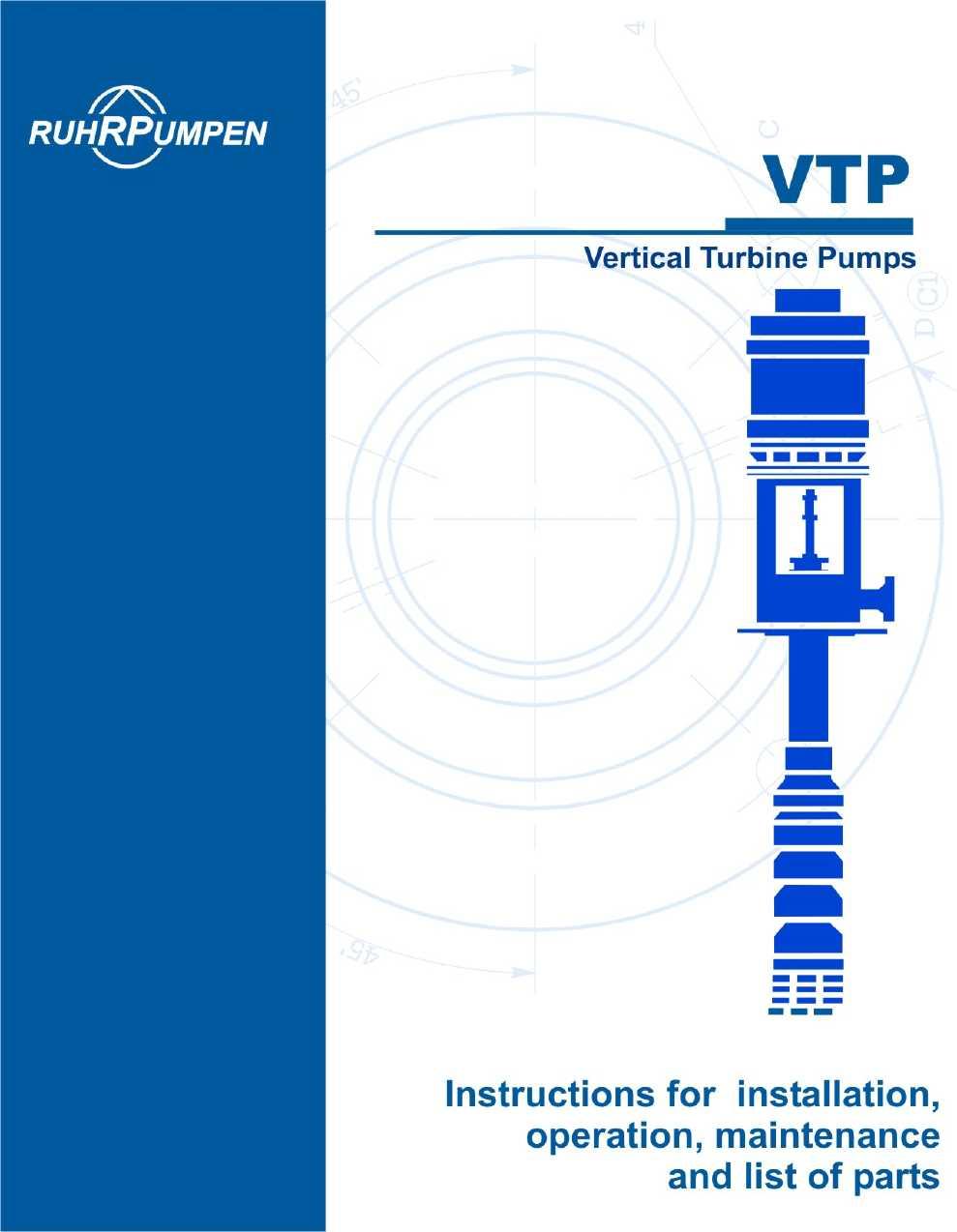
2 2 / 27 Ruhrpumpen, Inc. products are the result of more than a century of progressive study and development. Advanced design, proper selection of materials, and precision construction reflect this wide experience. Ruhrpumpen products will give trouble-free efficient operation with minimum maintenance and repair. This instruction book will familiarize management and operating personnel with pertinent details and proper procedures for the installation, operation, and maintenance of one of these products. Designate below your identification of the equipment for which this book applies. NOTE: BOWL SERIAL NUMBER IS STAMPED ON DISCHARGE CASE FLANGE AS SHOWN IN FIGURE 2-1 STUDY THIS INSTRUCTION BOOK The descriptions and instructions included in this book cover the standard design of the equipment and any common deviations when possible. this book does not cover all design details and variations nor does it provide for every possible contingency which may be encountered. When information cannot be found in this book, contact the nearest Ruhrpumpen office. Do not operate this equipment in excess of its rated speed, pressure and temperature, nor otherwise than in accordance with the instructions contained in this manual. This equipment (or a prototype) has been shop tested and found satisfactory for the conditions for which it was sold, but its operation in excess of these conditions will
3 3 / 27 subject it to stresses and strains which it was not designed to withstand. Failure to heed this warning may result in a accident causing personal injury. SECTION l INTRODUCTION AND GENERAL DESCRIPTION 1-1. INTRODUCTION 1-2. This instruction book contains a description of and instructions for open and enclosed type bowl assemblies used in Ruhrpumpen vertical turbine pumps and manufactured by the vertical Pump Division of the Ruhrpumpen. Instructions for disassembly, maintenance, and reassembly are given in section II. A list of parts covering all models of the bowl assembly, and instructions for ordering parts, are given in section III GENERAL DESCRIPTION 1-4 Ruhrpumpen vertical turbine pumps are normally designed to operate in wells or sumps. The bowl assembly (see figure 1-1) consists primarily of a suction case or bell, one or more pump bowls, and a discharge case. The number of stages (bowls) employed is determined by the head requirements of the installation. The pump bowl assembly is positioned in the sump or well at a depth to provide the proper submergence. A pump shaft, common to all moving parts in the bowl assembly, provides mechanical linkage to the pump driver unit two basic configurations of the bowl assembly are the open type and the enclosed type. Functional differences in the two types are in the methods employed to lubricate the line shaft. In the enclosed type, a tube is placed over the line shaft and lubricants are supplied to the bearings through the shaft tube. In the open type, no lubricants are used other than the fluid being pumped 1-6 SUCTION BELL 1-7. The suction bell serves as the input port to the pump bowls. Internal guides or vanes perform the dual function of directing fluids into the eye of the first stage impeller and supporting the housing for the suction case bearing. A bell type suction is normally employed, but in applications where it is necessary to attach a suction column, a flanged type of suction case may be used. 1-8 PUMP BOWLS Two types of pumps bowls, top and intermediate, are available for the vertical turbine pump. Operation of the bowls is identical, with the exception that the top bowl discharges fluids into the discharge case and that the intermediate bowl or bowls discharge fluids into the eye of the impeller of the next stage. Each type of bowl contains an impeller which is mechanically connected to the pump shaft. Liquid flow in the impeller is both axial and radial. the upper portions of the bowls contain vanes which direct the fluids from the impeller out of the bowl. The vanes also support the housing for the bowl bearings, intermediate bowls contain a bronze bearing press fitted into the housing. Top bowls contain a single bronze bearing which extends up into the discharge case. Bearing materials may be varied to suit specific application. A multiple stage assembly contains a top bowl and one or more intermediate bowls. A single stage assembly contains only a top bowl IMPELLER Impellers used in Ruhrpumpen turbine pumps are of the enclosed centrifugal or mixed flow type. Sealing of interstage leakage is accomplished by insertion of wearing rings to provide close radial fitting between the bowl and impeller sealing surface. Impellers are mechanically connected to the pump shaft by impeller collets and lock nuts which press the impeller tightly against the collets. Position of the impeller on the shaft is determined by an impeller lock pin. The lock pins are inserted at the plant and the provide accurate positioning of impellers on the pump shafts.

4 4 / DISCHARGE CASE The discharge case receives the fluid from the top bowl and directs it to the column pipe, if one is used, or directly into the discharge head. Vanes that guide the fluid also act as a support for the pump shaft bearing. When the discharge case is used with enclosed shaft pumps, the tapped holes in the external boss of the discharge case provide venting of the pump discharge pressure, and permits correct flow of lubricants down the enclosing tube. When the discharge case is used with an open type pump, threaded plugs are screwed into the holes to prevent by-passing of liquids through the vent ports. FIGURE 1-1. INSTALLATION
5 5 / 27 SECTION II PRE-INSTALATION 2-1. INSPECTION OF EQUIPMENT 2-2. Immediately on receipt of the equipment inspect and check it against the shipping manifest. Examine the create and wrapping before discharging. Parts or accessories are sometimes wrapped individually or fastened to the crate. Report any damage or shortage to the transportation company s local agent. 2-3 STORAGE 2-4. When it is necessary to store a pump for a short time before it can be installed, place it in a dry location. Protect it thoroughly from dust and moisture. If a pump is schedule for storage for an extend period of time, that section of the pump above the bearing bracket should be dismantled and all internal surfaces subject to corrosion should be coated with a protective fluid. 2-5 CLEANING PRIOR TO INSTALLATION 2-6. If a rust preventative has been used on stored parts, they should be thoroughly cleaned prior to putting the pump into service. Kerosene or any coal tar distillate will generally serve as a good solvent for most rust preventative compounds. Extreme care must be taken to assure that all traces of the protective coating are removed unless standard lubricating oil has been used for protection. SECTION III INSTALATION 3-1 LOCATION OF EQUIPMENT 3-2. The pump should be placed so that it can be easily removed for inspection and repair, giving due attention to desirability of simplifying the discharge piping layout. There should be ample head room to allow the use of an overhead crane of lifting device with sufficient capacity lo lift the entire unit. 3-3 FOUNDATION 3-4. The foundation may consist of any material that will afford permanent rigid support to the full area of the pump or driver supporting member an will absorb expected strains and shocks that may be encountered in service. If the pump is to be mounted on a concrete floor, foundation bolts of the specified size should be located according to the elevation drawing. Each bolt should be surrounded by a pipe sleeve 2 to 3 times the diameter of the bolt. The sleeve should be held rigidly yet allowing the bolts to be removed When the pump unit is mounted directly on a sump cover, it should be located as near as possible to supporting beams or building walls to prevent deflection and vibration. The pump support and motor base should be bolted and doweled to the sump cover to retain proper alignment of piping. 3-6 EQUIPMENT NECESSARY FOR INSTALLATION 3-7. The equipment necessary for the equipment is the following: A. Foundation bolts and nut when is necessary. B. Leveling pieces as wedges. C. Adapted the derrick, tripod or common crane with hoisting chain or similar accessory that has hook and revolvable link.

6 6 / INSTALLATIONS 3-9. Before start the installation is recommended to hire and electrician to connect the motor after the instillation. WARRING: You should take out the residuals and loose materials of the well before installing the pump. If is used a strainer, be carefully during the transportation CLOSE LINE PUMPS A. Cover the opening of the foundation with wooden or any another material to protect the well from objects that can fall in. B. Place in the due position the hoist, with the hook and the revolvable link centered on the foundation opening. C. If it will use a strainer and a suction tube, install the strainer in the bottom end of the suction tube. Then put a clamp to the suction tube top end and lift until the tube is centered on the foundation opening. I. Take of the line plugs and pre-ensemble close tube and take out the line 8 inches. Note: If the line that will be used has a smaller diameter than the shaft of the pump, the close tube should be reduce and should use a preensambled assembly instead of the line and the pre-ensambled close tube should be used for the first section that is over the bowl assembly. J. Insert the line and the close tube or the assembly in the column tube and let the line extreme stood out 1 feet. K. With a rope makes you two simple moorings around the close tube and two simple moorings around the column tube. L. Put a clamp in the column tube just down of the coupling. D. Take off the wooden that cover the foundation and put the suction tube with the strainer inside the well until the clamp rest over the foundation. NOTE: Before you continue the bowl assembly installation, measure the shaft length to compare it later when the impeller be adjusted. E. Put the tube clam on the top bowl assembly and lift until it is over the suction tube. Note: when bowl assembly of 6 or 8 inches is installed keep the bowl firmly locked to the same wood that was join when was shipped, until de bowl assembly is vertically. F. Down the bowl assembly and thread it in the suction tube. Warring: On the close shaft pump do not cover the discharge case openings. Installation of the Bowl Assembly H. Down the bowl assembly until the clamp rest over the foundation.

7 7 / 27 S. Take out the column tube and the bowl assembly until the column tube clamp rest over the foundation. T. Put the spacer on the column tube and check that the dimensions of the top part of the spacer to the top part of the line is 15½ inches. U. Check that the dimension of the top part of the close tube to the top part of the line is 9½ inches. V. Putt oil inside de close tube during the installation of each section to assure the appropriate lubrication of the line bearings for the initial mounting. See lubrication instructions, section V. W. Install a line bearing on the close tube stood out. Use thread antihardening in all the line bearing thread. Installation of the Column Tube M. Fasten the sling to the column tube clamp, and lift until the bottom end of the tube is centered on the bowl assembly. N. Down slowly the column tube, the line and the close tube until the line can fit en the shaft line. Take out the thread protector. O. Take out the line rope, putt oil on the line threads and turn the line to the left to fit it on the shaft line. P. Take out the rope of the line close tube and of the column tube. Turn the close tube to the left to fit the discharge tube connector bearing. Q. Down the column tube and turn it to the right to fit it with the bowl assembly. R. Lift a little the column tube and the bowl assembly and take out the bowl assembly clamps. X. Put oil on the line thread and then install a coupling on the line stood out, make sure that the coupling is centered. NOTE: Put the column tube retainer bearing on intervals of 30 feet for axes of ¾ and 1 inches and on intervals of 50 feet for axes of 1¼ inches and up. Y. Repeat operations from "I" to "W until the bowl assembly have gone down to the appropriate depth of the well. Z. If you are going to put the discharge under the floor install on the discharge T on the appropriate place. Aa. Connect the pump top line to the line. Ab. Connect the top line close tube to the line close tube. Ac. Invest the pump head, center the top column flange packing on the bottom of the head and assure with bolts the top column tube on the bottom of the head.
8 8 / 27 NOTE: During the assembly of the top column flange tube to the bottom of the head, check carefully that the packing is center and that all the tube is aligned after assembly. Ad. Fasten a sling to the head elevator hooks. Ae. Ascend the head with the top column tube, take out the thread protector and descend them over the top line. Af. Turn the top column tube and the head to the right to thread the top column tube in the column tube coupling. Ag. Ascend a little the head and the column tube and take out the tube clamp. Ah. Turn the pump until the discharge head o the T under floor be in front in the properly direction to join the discharge tube and the assembly holes with the foundation assembly holes Ai. Settle the pump over the foundation and level it. Aj. Take out the pump sling. Ak. Insert a O ring in the groove that is inside the split gland y descend the split gland over the top line. Al. Center the split gland over the close tube of the top line and descend it carefully permitting to the ring O and the split gland to slide to the outside of the top line close tube. Am. Fasten with bolts the split gland to the discharge head. An. Slide the tube tension bearing or sees the top line and turns it to the left, pressing it manually. Then press one or one and a half turn approximately for each 100 feet of pump length to achieve the properly tension if the close tube. NOTE: On the pumps with close line water lubrication should additional assembly packing, split gland and its nuts. Ao. Align the hole of the adjust screw of the tension bearing with the thread hole closest to the split gland top. Then insert the adjust screw and tight. Ap. Fasten with bolts the assembly support and the oiler to the head side. Aq. Connect the manual valve or solenoid, the visual feeding valve of oil, and the accessories to the oiler. Ar. Connect the lubrication accessories to the tension bearing OPEN LINE PUMPS Cover the opening of the foundation with wooden or any another material to protect the well from objects that can fall in. B. Place in the due position the hoist, with the hook and the revolvable link centered on the foundation opening. C. If it will use a strainer and a suction tube, install the strainer in the bottom end of the suction tube. Then put a clamp to the suction tube top end and lift until the tube is centered on the foundation opening. D. Take off the wooden that cover the foundation and put the suction tube with the strainer inside the well until the clamp rest over the foundation. NOTE: Before you continue the bowl assembly installation, measure the shaft length to compare it later when the impeller be adjusted. E. Put the tube clam on the top bowl assembly and lift until it is over the suction tube. NOTE: when bowl assembly of 6 or 8 inches is installed keep the bowl firmly locked to the same wood that was join when was shipped, until de bowl assembly is vertically. F. Down the bowl assembly and thread it in the suction tube.

9 9 / 27 G. Ascend the bowl assembly with the suction tube and take out its clamp. H. Descend the bowl assembly until the clamp rest over the foundation. I. Insert a line section inside a column tube section, having care that the sleeve is on the top extreme. Leave to the line stand out 1 feet on the bottom column tube. J. With a rope make two simple moorings around the close tube and two simple moorings around the column tube. T. Install a coupling in the top line stand out taking care that the coupling is center. U. Repeat the operations from I to T until the bowl assembly have gone down to the appropriate depth of the well. V. If you are going to put the discharge under the floor install the discharge T on the appropriate place. W. Connect the pump top line to the line. K. Fasten a top column tube clamp and then ascend the column with the line and center the bowl assembly. I. Descend the column tube with the line, take out the thread protector and continue descending until the line rest over the axe pump coupling. M. Take out the line rope, put oil on the threads of the line. N. Connect the line to the pump line, turning th line to the left. O. Tight the connection. P. Descend the column tube over the coupling of the bowl assembly and turn the column tube to the right until be tightly coupled to the bowl assembly. Q. Ascend the bowl assembly and take out its clamps. R. Guide by hand the bowl assembly and the column tube inside the well and descend it until the discharge tube clamp rest over the foundation. S. Insert a bearing support over the line and tight on the coupling of the column tube until it stay firmly over the column tube, check that the dimension to the top flange to the top line stand out15½ inches. Pump head Installation X. Invest the head and center the packing of the top column flange on the top of the head. Then assure them with bolts. NOTE: During the assembly of the top column flange tube to the bottom of the head, check carefully that the packing is center and that all the tube is aligned after assembly.
10 10 / 27 Y. Fasten a sling to the head elevator hooks. Z. Ascend the head with the column tube attached, take off the thread protector y descend the top axe. Aa. Turn the top column and the head to the right to thread the top column tube on the coupling of the column tube. Ab. Ascend a little the head and the column tube. Ac. Take off the clamp of the tube. Ad. Turn the pump until the discharge head or the T under the floor be in front the properly direction to join the discharge tube an the assembly holes with the foundation assembly holes. Ae. Settle the pump over the foundation and level it. D. Descend slowly the driver over the head of the pump taking care that the assembly holes and head are aligned. E. Take out the sling of the pump and the elevator. F. Fasten with bolts the driver to the head and fasten with bolts the head to the foundation. G. Connect the discharge pipeline, taking care of align the pipeline with the discharge. The pipeline support should be independent. H. Check that the top shaft is on the center of the hollowshaft driver. If is necessary center de top shaft and should have the security that the driver is rotating in the property direction, putting in operation the driver just for a second. I. Install the adjusting nut on the top shaft and tight until the adjusting nut rest on the clutch and the pump rotate without problems. Af. Take off the pump sling. Ag. Slide the split gland over the line and assure with bolts the discharge head. Ah. Install the packing on the split gland, settle each ring of the split gland. NOTE: When is used a retainer cage, install tree packing rings, followed by the retainer cage and 2 packing rings. Ai. Install the split gland and tight only with the hand the nuts of the split gland bolts. Aj. Install the water deflector HOLLOWSHAFT DRIVERS A. Take out the driver clutch. B. Fasten a sling to the driver. C. Ascend the driver and center it on the top shaft. NOTE: The pump shaft goes lengthening by the hydraulic push of the pump. It is necessary to ascend the impellers to compensate the lengthening. K. Ascend the impellers the same quantity of the lengthening tightening the adjust nut. L. Tight the adjust nut one o twice turns. M. If the total adjustment is larger than the longitudinal game wrote the paragraph 3-10 o 3-11, go back the nut until the total adjustment is slightly smaller than the longitudinal game PROPULSION IN RIGHT ANGLE FOR THE HOLLOWSHAFT A. Take out the clutch of the propulsion in right angle. B. Fasten a sling to the propulsion in right angle.
11 11 / 27 C. Ascend the propulsion in right angle and center it over the head. D. Descend slowly the propulsion in right angle over the head, taking care that the assembly holes of the two units are aligned and the coupling of the propulsion in right angle is turned to de driver. E. Cover the surface of the grout with wet sackcloth so that it can drying off slowly. After the grout has forged for 48 hours, remove the wooden form and plane the surface. Let the grout forged 72 hours before operate the pump. E. Take out the propulsion and the elevator equipment. F. Fasten the propulsion bolts to the head and the head bolt to the foundation. G. Connect the discharge pipeline to the pump, taking care to align it. The pipeline support should be independent of the pump. H. Check that the top shaft is in the center of the hollowshaft of the propulsion right angle. If is necessary center the top shaft. I. Install the clutch on the top shaft with a cotter and assure the clutch of the hollowshaft of the propulsion right angle. J. Repeat the operation form J to M of the paragraph GROUT 3-15.The grout avoids the lateral displacement of the discharge but it doesn't correct the irregularities of the foundation. To grout the pump follow the next steps: A. Build a wooden form around the discharge head to contain the grout. B. Mix the grout using a part of cement and two parts of construction sand and enough water to make pasta. C. Wet the foundation very well with water and toss the grout in the wooden form, making sure that the mixture flows freely under the discharge head. D. With a rigid wire revolve the grout to make the air, that can have, come out.


12 12 / 27 Pump Push Factors Installing the Driver on the Hollowshaft Adjust Nut Installation

13 13 / 27 Centering the Line Placement depth Feet (meters in parenthesis) Calculate the hydraulic push multiplying the total high per the pump push factor. The shaft lengthening taken of the graphic should not exceed impeller shaft longitudinal game that is shown on the operational curve.
14 14 / 27 SECCION IV FUNCIONAMIENTO 4-1. PREVIOUS TO STARTING RECOMMENDATIONS 4.2 Previous to starting recommendations, check the following thinks: A. The discharge valve is partially open and the discharge pipeline is property connected. B. The impellers have been adjusted properly during the installation and the motor line and the pump turn without inconvenient. C. All the bolts are tight STARTING 4-4. Start up the pump like it follows: A. Pre-lubricate the line in the pump of open line injecting water per the opening injection of the discharge head. Inject water for a minimum of three minutes in the pump whose shaft longitude is bigger than 40 feet. Continue the injection for one minute for each 100 additional feet of longitude of the shaft. B. Close the outburst switch. C. Observe if the pump begins to work easily and if it works without excessive vibration. If there is a difficulty to begin or an excessive vibration, stop the bomb immediately and consult the section V to determine the probable cause. D. Open the discharge valve slowly until the discharge pressure arrives to the wanted degree. E. In the open line pumps, tight the nuts of the split gland gradually during a lingering period. (See you the paragraph 5-8) FINAL ADJUSTMENT 4-6. After the pump start to worked for a while enough to press the line coupling and to clean the liquid pumped of abrasive materials that can have, the position of the impellers should be checked and to readjust them for a turn of the adjust nut in the motors of hollowshaft STOPPING UNIT 4-8. Close the discharge valve slowly and then stop the motor. With this pulsations are avoided in the system and that the liquid is returned through the pump. SECTION V CONSERVATION 5-1. PREVENTIVE CONSERVATION 5-2. INSPECTION 5-3. the pumps with hidden shaft are built to lend service without inconveniences for a long time and to only need a minimum attention. Periodically inspect the oiler to see if it is working appropriately and if it has enough oil, as well as the split gland to see if it has the appropriate escape, and the pumps to see if there are slack fasteners, excessive vibration, dirt and corrosion CLEANING 5.5. Remove the rust or corrosion with a brush of fine wire and cloths. Clean all the pieces, if is necessary, except the electric contacts, wetting the cloths or the brush with an appropriate solvent PUMPS WITH OVERDRAFT SHAFT 5-7. The pumps with overdraft shaft are equipped with split gland that do not need
15 15 / 27 attention, however it need an occasional approve of the scape Don't press the case of the split gland as much as to impede all escape. The packing should have a slight escape for the lubrication or the shaft will be lined or it will suffer excessive waste if was impeded that escape completely. The best rule is to loosen the case so that it can be given turns to the nut with the fingers and to let the split fland to have an abundant escape during an initial period of setting in march or after the packing of the split gland has been changed. Tight then the nut of the case gradually letting that the packing settles, until the escape is reduced to between 40 and 60 drops per minute. 5-9.The modeled rings that can be requested as reserve packing, give the best results to renovate the packing. Nevertheless, it can be formed the material rings in rolls, if it is necessary. In that case the pieces will be cut individually and will be adjusted carefully with juncture to bevel to avoid the deformation of the pieces. Put each new ring inside the split gland and set individually with the case. Make sure that the junctures are not aligned. The best thing is to stagger them to 180 degrees as they go settling the new rings in the split gland CLOSE SHAFT PUMP This kind of shaft are provided with a oil lubricant tank, that should be filled periodically. Fill the tank like is recommended in the next paragraph LUBRICATION OPEN SHAFT PUMP This kind of pump depend mainly on the liquid that is pumped for the lubrication of the bearings, intermediate and superior bowls, the bearing of the discharge case and the bearings of the shaft. Conserve the grease cup of the split gland full with good quality grease. The bearing of the suction case is packed with grease in the factory and it doesn't need lubrication until it is dismantled to inspect it or to repair it. After the disassembly, repack the suction box bearing with grease of medium viscosity to the temperature of the liquid pumped (approximately 500SSU to 100 degrees). Is convenient an oxidation inhibitor and usually have it the most of the good quality grease CLOSE SHAFT PUMP These pumps have the bearings of the discharge case and shaft lubricated with oil. The lubricant for those bearings is contained in the oil tank and it is fed to the bearing of tension tube. Maintain the oil tank full with a thin oil of turbine of good quality, of around 150 SSU to the temperature of the liquid that is pumped. A less thicken oil maybe doesn't flow appropriately through the bearings. Adjust the oiler so that it feeds from 4 to 6 drops per minute (twice that quantity for pumps larger than 200 feet, inside the shaft tube. As in the pumps open pumps, the bearings of the bowls are lubricated for the liquid that is pumped. The bearing of the suction case is greased and sealed in the factory and you only have to repack after disassembling to inspect it or to repair it. After disassembling it repack that bearing like is recommended for the open shaft pumps CONSERVATION CORRECTIVE INCONVENIENCES AND THEIR POSSIBLE CAUSES THE PUMP DO NOT START UP The possible causes are: A. The voltage given to the driver is very low. B. The electric circuit is open. C. The motor is faulty. D. The pump is forced inside a bent hole or against an obstruction in the hole or drain. E. The impellers are begun against the bowl because the bearing has a faulty adjustment or is wear.
16 16 / THE PUMP DOESN T DISCHARGE LIQUID. The possible causes are: A. Low velocity because the voltage or the shaft frequency is low. B. Incorrect direction of the rotation. C. The total height of pumping can be bigger than the height for the one that the pump is built. D. The strainer is obstructed or has strange matters blocking the liquid. E. The lowest impeller is not always submerged. F. The shaft is broken INSUFFICIENT CAPACITY. The capacity cannot be enough for the next causes: A. Little speed of the pump for reasons of low voltage to low frequency in the line. B. The total height of pumping can be bigger than the height for the one the bomb is built C. The liquid pipes or the strainer can be partially obstructed. D. The impeller is slack. E. To the suction head is entering air or vapor. F. The level of the liquid in the well or drain is too low THE PUMP LOSS THE PRIMING AFTER START. The pump can lose its priming after starting up if the level of the liquid descends under the pump. This can happen when the quantity of the liquid pumped it is smaller than the capacity of the pump THE PUMP OVERLOADS TO THE DRIVER. The cause that the pump can overload to the driver are: A. Operation in a point of the curve different to the design. B. The liquid pumped is not of the specific gravity for which the pump was built. C. The line voltage is very low or the driver is faulty. D. The impellers touch up or below THE PUMP VIBRATES. The vibration of the bomb can be caused for: A. Worn bearings. B. The shaft is out of line or bent. C. The assembly bolts are slack or the foundation is not rigid D. The impeller causes an imbalance to be corrode or partially obstructed. E. To the bowl body is entering air or vapor. F. Effort due to misalignment of the pipe. G. The well is bent or there are an obstruction that causes an obstacle effect WEAR EXCESSIVE. The cause of the excessive waste can be: A. Sand or another abrasive material in the liquid pumped. B. The well is bent or there are an obstruction that causes an obstacle effect. C. Vibration, if is not remedied immediately CORROSION. The corrosion can be caused by sludge in the water or for the liquid class that is pumped. It can decrease the corrosion to the minimum using pieces of stainless steel, brass or metal model.
17 17 / REPAIRS CLOSE SHAFT PUMP The repairs of the close shaft pump consists on take out the pump and to dismantle it to replace the faulty pieces. A elevator is needed, like the described in the installation, to take out the pump of the well. Take out the bomb and disarmament as follows: A. Disconnect the electrical force and the electric drivers that go to the motor, putting labels. This should be made by a competent electrician. Disconnect the electric force of the motor and also the electric conductive that go to the motor, putting labels. This should be made by a competent electrician. B. Remove the covered with the top part of the motor and remove the screw of the adjust nut (2) and the adjust nut (1) of the top end the top shaft. C. Take out the driver clutch. D. Take out the bolts (457) that assure the driver to the discharge head. E. Fasten a sling to the elevator holes of the driver and ascend the driver vertically until the top shaft gets free. F. Descend the motor on an appropriate support that has gotten ready. NOTE: Have the security to have a clean and sufficiently wide space to go placing the pieces in the same order in that you leave taking out. G. Disconnect the oil pipe of the tension nut of the shaft tube. NOTE: In the close shaft pumps water lubrication should be taken out the packing and the additional packing cases before taking out the tension nut of the pipeline. H. Remove the adjustment screw that holds the tension nut of the pipeline giving turns to the right I. Take out the split gland removing the bolts that assure it (458) J. Disconnect the discharge pipeline of the pump K. Remove the bolts that assure the pump to the foundation. L. Fasten a sling to the hooks elevators of the pump until the column tube overdraft. M. Place the clamp to the column pipe band in the column tube under the first coupling and descend the pump until the clamp rests on the foundation. N. Disconnect the top column tube of the column tube coupling giving turns to the left. O. Ascend the pump and the top column tube and take off the top shaft and the top close tube. P. Ascend the column tube until the next coupling is overdraft (24). Q. Place a clamp in the column tube over the coupling and descend the column tube until the clamp rest on the foundation. R. Disconnect the column tube on the coupling and ascend the column tube to leave overdraft the conjunction of the close tube. S. Assure with a rope the close tube to the column tube. T. Disconnect the close tube on the coupling and ascend the column tube with the close tube until overdraft the coupling of the shaft (23). U. Assure with a rope the shaft to the close tube and the column tube. V. Disconnect the shaft.
18 18 / 27 W. Descend the column tube, the close tube and the shaft until placing them on an appropriate support. X. Disassembly the individual sections of the shaft and of the close tube. Y. Disconnect the other sections of the column tube, of the close tube and the shaft, repeating the operations from " K " until " S " until arriving to the bowls assembly. Z. Ascend bowl assembly until overdraft the suction tube, if this is installed. Aa. Place a clamp in the suction tube and descend the bowl assembly until the clamp rests on the foundation. Ab. Disconnect the bowl assembly and place it in and horizontal position to dismantle it. Ac. Ascend the suction tube taking it out of the well and descend it until place on an appropriate support Clean all the pieces minutely with an appropriate solvent, put on the shaft oil lightly with a thin turbine oil and arm the pump in inverse order of disassembly like it is described in the operation "Y" of the paragraph Reinstall the pump like it is described in the section III OPEN SHAFT PUMP The repair for these pumps is similar to the repair of the close shaft pumps. Take out and disassembly the bomb like it continues: A. Take out the driver like it is described in the operations from "A" to "F" of the paragraph B. Disconnect the discharge pipe. C. Remove the water deflector (6) D. Take out the split gland (9) removing the nuts (8) of this split and lifting it. E. Take out the split gland (17W) removing the bolts that assure it. F. Take out and discard the packing (15W) of the split gland. G. Remove the bolts that assure the pump to the foundation. H. Fasten a sling to the elevator hooks of the pump and ascend the pump vertically until it overdraft the column tube. I. Place a clamp in the column tube under the first coupling and descend the pump until the clamp rests on the foundation. J. Disconnect the top column tube of their coupling giving him turns to the left. K. Ascend the head and the top column tube until taking them out of the top shaft (19). L. Disconnect the top shaft (19) of the shaft (23) in the coupling, holding the coupling and giving turns to the shaft to the right. The threads are to the left. M. Ascend the column tube until it overdraft the following coupling. N. Place a clamp in the column tube under the coupling and descend the column tube until the clamp rests on the foundation. O. Disconnect the shaft of the coupling, holding the coupling and giving turns to the shaft to the right. P. Ascend the column tube with the shaft and then descend until placing it on an appropriate support. Q. Repeat operations from " R " to " P " until arrive to the bowl assembly. R. Ascend the bowl assembly until it overdraft the suction tube, if is installed. S. Place a clamp in the suction tube and descend the group until the clamp rests on the foundation.
19 19 / 27 T. Disconnect the bowl assembly of the suction tube and place in horizontal position to dismantle it. U. Ascend the suction tube taking it out of the well and descend until placing it on an appropriate support Clean all the pieces minutely with an appropriate solvent, put on the shaft oil lightly with a thin turbine oil and arm the pump in inverse order of disassembly like it is described in the operation "Y" of the paragraph Reinstall the pump like it is described in the section III. SECCION VI LIST OF PARTS 6-1. GENERAL 6-2. The requirement for stock of spare parts will vary with the severity of conditions of service, the extend of field maintenance anticipated, and the number of units installed. A minimum of one spare of each moving part should be stocked, as well as a complete set of bearing and seals. 6-3 ORDERING PARTS 6-4. When ordering spare and replacement parts the pump serial number, size and type of pumps must be given. Refer to the nameplate. This information is essential in order that Ruhrpumpen may identify the pump and furnish the correct repair parts. Give the name and number of the part as listed in the parts list of the sectional drawing applicable to the pump, the quantity required and where possible, the complete symbols stamped on the old part. Orders for replacement parts should be sent to the nearest Ruhrpumpen office.
20 PART LIST HEAD TYPE T 20 / 27
21 PART LIST HEAD TYPE L 21 / 27
22 PART LIST FLANGED BOWL ASSEMBLY WATER LUBRICATION 22 / 27
23 PART LIST THREADED BOWL ASSEMBLY WATER LUBRICATION 23 / 27
24 PART LIST FLANGED BOWL ASSEMBLY OIL LUBRICATION 24 / 27
25 PART LIST THREADED BOWL ASSEMBLY OIL LUBRICATION 25 / 27
26 26 / 27 USA RUHRPUMPEN, Inc South 86th East Ave. Tulsa, Oklahoma USA Phone:+1 (918) GERMANY RUHRPUMPEN GmbH Stockumer Strasse Witten/Germany P.O. BOX Witten/Germany Phone: +49 (2302) MEXICO RUHRPUMPEN S.A. de C.V. Níquel No Ciudad Industrial Mitras García, NL México Phone: +52 (81) EGYPT RUHRPUMPEN Egypt 2 New Marwa Building Ahmed Tayssir Str. 2nd Floor Heliopolis Cairo, Egypt Phone: +20 (02) ARGENTINA RUHRPUMPEN S.A. Oliden 3177 C1439FNG Buenos Aires, Argentina Tel: +54 (11)

27 27 / 27 May 2004
Installation, Operation and Maintenance LOK-FLANGE Multitube Heat Exchangers
 Bulletin 1200/4 (Revised 5/12) Installation, Operation and Maintenance LOK-FLANGE Multitube Heat Exchangers INNOVATORS IN HEAT TRANSFER I. INSTALLATION OF HEAT EXCHANGERS A. HEAT EXCHANGER SETTINGS 1)
PhiloWilke Partnership Addendum No. 2 A/E Project No April 2016
 SECTION 23 21 23 PART 1 - GENERAL 1.01 RELATED DOCUMENTS A. Drawings and general provisions of the Contract, including General Conditions and Division 01 Specification Sections, apply to this Section.
Full-line Product Overview
 Full-line Product Overview End Suction Centrifugal Pumps This general purpose pump can be configured in frame-mounted and close-coupled, semi-open and enclosed impeller configurations. They are available
N N O V A T I O N E F F I C I E N C Y Q U A L I T Y VTP. Vertical Turbine Pump
 N N O V A T I O N E F F I C I E N C Y Q U A L I T Y VTP Vertical Turbine Pump For more than 60 years the name Ruhrpumpen TM has been synonymous worldwide with innovation and reliability for pumping technology
DS series STERLING PUMPS. Industrial End Suction Pumps ISO/DP
 DS series Industrial End Suction Pumps ISO/DP 5199 www.sterlingpumps.com.au DS series Capacities from: Heads from: 340 to 5,680 m3/h (1,500 to 25,000 USPGM) 21 to 106 metres (70 to 350 feet) Power range
DENVER PUBLIC SCHOOLS DESIGN AND CONSTRUCTION STANDARDS This Standard is for guidance only. SECTION PUMPS
 PART 0 A/E INSTRUCTIONS 0.01 Design Requirements A. Pumping system design 1. A primary-secondary pumping system is preferred. Redundant pipes are required for chillers and boilers. 2. Select pumps to operate
Pumps SELECTION OF A PUMP
 Pumps SELECTION OF A PUMP A water system needs to move the water produced from the source to its customers. In almost all cases in Minnesota, the source is at a lower elevation than the user so the water
INSTALLATION, OPERATION, AND MAINTENANCE MANUAL
 INSTALLATION, OPERATION, AND MAINTENANCE MANUAL TUBE AXIAL FANS BTA, WTA, HTA, DDA The purpose of this manual is to aid in the proper installation and operation of the fans. These instructions are intended
SECTION STEAM CONDENSATE PUMPS
 PART 1 - GENERAL 1.1 DESCRIPTION SECTION 23 22 23 STEAM CONDENSATE PUMPS SPEC WRITER NOTES: 1. Delete between // ---- // if not applicable to project. Also delete any other item or paragraph not applicable
SELF-PRIMING CENTRIFUGAL PUMPS BMLS-M & BMLS-H
 SELF-PRIMING CENTRIFUGAL PUMPS BMLS-M & BMLS-H INSTALLATION, OPERATION & MAINTENANCE INSTRUCTIONS HP Phase Medium Head High Head 3 1 BMLS 300 M BMLS 300 H 3 3 BMLS 300 M3 BMLS 300 H3 5 1 BMLS 500 M BMLS
568X, 587X, 588X Series
 Please read and save this Repair Parts Manual. Read this manual and the General Operating Instructions carefully before attempting to assemble, install, operate or maintain the product described. Protect
N N O V A T I O N E F F I C I E N C Y Q U A L I T Y
 N N O V A T I O N E F F I C I E N C Y Q U A L I T Y Standard Pumps Manufacturing Plants Today Ruhrpumpen is a worldwide company, with a network of global manufacturing plants in different countries and
"S" SERIES IMMERSIBLE PUMP OWNER'S MANUAL INSTALLATION OPERATION PARTS Models S12 S16
 Webster Pumps "S" SERIES IMMERSIBLE PUMP OWNER'S MANUAL INSTALLATION OPERATION PARTS Models S12 S16 PLEASE READ THE FOLLOWING INFORMATION PRIOR TO INSTALLING AND USING Webster PUMPS or HAYWARD VALVES,
Horizontal Split Case Pumps Type U
 Horizontal Split Case Pumps Type U 7.1 7.2 Stage U Type Pumps Features: Axially Split Case Design Range from 20M 3 /Hr to 600M 3 /Hr Two Stage Pump Single Suction Twin Volute Casing Design Closed type
A. Operation and Maintenance Data: For pumps to include in emergency, operation, and maintenance manuals.
 SECTION 23 21 23 - HYDRONIC PUMPS PART 1 - GENERAL 1.1 RELATED DOCUMENTS A. Drawings and general provisions of the Contract, including General and Supplementary Conditions and Division 01 Specification
FAIRBANKS NIJHUIS SOLIDS HANDLING PUMPS.
 FAIRBANKS NIJHUIS SOLIDS HANDLING PUMPS www.fairbanksnijhuis.com FAIRBANKS NIJHUIS History and Development Since the early part of this century, Fairbanks Nijhuis Pump has set industry standards in innovative
SuperKlean Washdown Products
 DURAREEL DR8 & DR8S INSTALLATION AND MAINTENANCE INSTRUCTIONS **DO NOT THROW AWAY AFTER INSTALLATION** **SAVE AND DISPLAY PROMINENTLY WHERE THIS EQUIPMENT IS USED** GENERAL WARNINGS High pressure and hot
Patterson/AMT Inline Circulator Pump Refer to pump manual for General Operating and Safety Instructions.
 Please read and save this Repair Parts Manual. Read this manual and the General Operating Instructions carefully before attempting to assemble, install, operate or maintain the product described. Protect
4 route 147, C.P.33 Coaticook, Qc J1A 2S8
 4 route 147, C.P.33 Coaticook, Qc J1A 2S8 TABLE OF CONTENTS INSTALLATION Nozzles p.3 Clearance for dismantling p.4 Foundations p.4 Foundation bolts p.5 Leveling p.5 Bolted joints p.5 Recommended bolt tightening
N N O V A T I O N E F F I C I E N C Y Q U A L I T Y INDUSTRIAL PUMPS. Catalog
 N N O V A T I O N E F F I C I E N C Y Q U A L I T Y INDUSTRIAL PUMPS Catalog Ruhrpumpen offers a wide range of standard pump designs and sizes providing energy efficient solutions for the vast majority
AC6 & AC8 HORIZONTAL SERIES Sealed Metallic Centrifugal Pumps Installation and Maintenance Instructions
 AC6 & AC8 HORIZONTAL SERIES Sealed Metallic Centrifugal Pumps Installation and Maintenance Instructions ASSEMBLY PUMPS WITH MOTORS 1. No assembly required. Unpack the pump and motor and examine for any
PUMPS FOR INDUSTRY. The Vertical Pump Specialists CONTENTS: Introduction & User List. Product Overview. Vertical Process Pumps...
 PUMPS FOR INDUSTRY CONTENTS: The Vertical Pump Specialists Introduction & User List Product Overview Vertical Process Pumps... Series 600 Vertical Sewage Pumps... Series 700 Vertical Sump Pumps... Series
LN series STERLING PUMPS. Horizontal Split Case Pumps. Double Volute. Single Stage.
 LN series Horizontal Split Case Pumps Double Volute. Single Stage www.sterlingpumps.com.au LN series Sizes: 6 to 42 Capacity to 12,500 m³/h Heads to 190 metres A rugged, single stage, double volute horizontal
OWNERS GUIDE TO INSTALLATION AND OPERATION
 OWNERS GUIDE TO INSTALLATION AND OPERATION SPM SERIES HIGH POWER CENTRIFUGALS READ THESE INSTRUCTIONS CAREFULLY Read these installation instructions in detail before installing your pump. Be sure to check
SERIES 'HE' PLASTIC HORIZONTAL PUMP MODEL: H2 x1½
 SERIES 'HE' PLASTIC HORIZONTAL PUMP MODEL: H2 x1½ OPERATION AND SERVICE GUIDE O-820_R FEBRUARY 2013 Refer to Bulletin P-201 and Parts Lists: P-7200, P-7250. SAFETY PRECAUTIONS BEFORE STARTING PUMP 1. Read
380 Series Multi-Stage Centrifugal Pumps
 380 Series Multi-Stage Centrifugal Pumps Flows to: 2,500 GPM Heads to: 2100 Feet Temperatures to: 500+ F TDH - Feet 140 Years of Pump Manufacturing American-Marsh Pumps, one of the oldest pump lines in
HORIZONTAL MULTISTAGE CENTRIFUGAL PUMP
 HORIZONTAL MULTISTAGE CENTRIFUGAL PUMP WWPPCHLFT260 Instructions WWPPCHLFT260_Horizontal Multistage Centrifugal Pump_IB.indd 1 READ THIS MANUAL CAREFULL BEFORE INSTALL, START THE PUMP 1. Suction 2. Plug
OPERATION & MAINTENANCE MANUAL FOR VIL VERTICAL INLINE PUMPS TYPES CS, CC, RC, AND DS
 OPERATION & MAINTENANCE MANUAL FOR VIL VERTICAL INLINE PUMPS TYPES CS, CC, RC, AND DS PATTERSON PUMP COMPANY A GORMAN-RUPP COMPANY PO Box 790 2129 Ayersville Road Toccoa, Georgia 30577 Telephone: 706-886-2101
Series 1140 and 1141 Temperature Regulators
 Hoffman Specialty Installation & Maintenance Instructions HS-504(E) Series 1140 and 1141 Temperature Regulators! CAUTION FOLLOW ALL INSTALLATION AND OPERATING INSTRUCTIONS. TURN OFF WATER OR STEAM BEFORE
.2 Section Waste Management and Disposal..5 Section Motors, Drives and Guards for Mechanical Systems.
 Issued 2006/08/01 Section 15131 Pumps Hydronic Systems Page 1 of 6 PART 1 GENERAL 1.1 RELATED SECTIONS.1 Section 01330 Submittal Procedures..2 Section 01355 Waste Management and Disposal.3 Section 01780
N N O V A T I O N E F F I C I E N C Y Q U A L I T Y INDUSTRIAL PUMPS. Catalog
 N N O V A T I O N E F F I C I E N C Y Q U A L I T Y INDUSTRIAL PUMPS Catalog More Than 60 Years Developing The Pumping Technology That Drives Progress Engineering Excellence Ruhrpumpen is an innovative
569, 570, 571, 572 Series
 Please read and save this Repair Parts Manual. Read this manual and the General Operating Instructions carefully before attempting to assemble, install, operate or maintain the product described. Protect
This label warns for risk of electrical shock when failing to observe.
 MANUAL horizontal centrifugal pumps MB series ic drive SB series mechanical seal 1. Introduction 2. Safety precautions 3. Receipt 4. Installation / Operation and Maintenance 4.1 Installation 4.2 Operation
Patterson/AMT Inline Circulator Pump Refer to pump manual for General Operating and Safety Instructions.
 Please read and save this Repair Parts Manual. Read this manual and the General Operating Instructions carefully before attempting to assemble, install, operate or maintain the product described. Protect
PUMPS FOR INDUSTRY. The Vertical Pump Specialists CONTENTS: Introduction & User List. Product Overview. Vertical Process Pumps...
 PUMPS FOR INDUSTRY CONTENTS: The Vertical Pump Specialists Introduction & User List Product Overview Vertical Process Pumps... Series 600 Vertical Sewage Pumps... Series 700 Vertical Sump Pumps... Series
"S" SERIES IMMERSIBLE PUMP OWNER'S MANUAL INSTALLATION OPERATION PARTS Models S2 S4 S5 SS6 SS7 S8
 Webster Pumps "S" SERIES IMMERSIBLE PUMP OWNER'S MANUAL INSTALLATION OPERATION PARTS Models S2 S4 S5 SS6 SS7 S8 PLEASE READ THE FOLLOWING INFORMATION PRIOR TO INSTALLING AND USING Webster PUMPS or HAYWARD
Installation of Glass Lined Equipment
 Installation of Glass Lined Equipment Information given herein is for guidance only and may not be complete. It is important that only trained and competent personnel are permitted to handle glass lined
Model 6050-Series. PumpAgents.com - buy pumps and parts online SELF-PRIMING PUMPS. Model 6050-Series
 PumpAgents.com - Click here for Pricing/Ordering Model 6050-Series SELF-PRIMING PUMPS FEATURES Body: Impeller: Shaft: Wearplate: Shaft Seal: Ports: Motor: Weight: Bronze Construction JABSCO Nitrile 316
1 1/8 Inch Centrifugal Pump Operation and Maintenance Guide
 1 1/8 Inch Centrifugal Pump Operation and Maintenance Guide Installation Location! The pump should be located as close as possible to the liquid source so that the suction line can be as short and direct
CPO N N O V A T I O N E F F I C I E N C Y Q U A L I T Y. ASME/ANSI B73.1 Chemical Process Pump. Springer Pumps, LLC
 N N O V A T I O N E F F I C I E N C Y Q U A L I T Y CPO ASME/ANSI B73.1 Chemical Process Pump Tel: 866-777-66 Horizontal Split Case For more than 6 years the name Ruhrpumpen TM has been synonymous worldwide
MODEL 652A MODEL 654A MODEL 652A MODEL 653A MODEL 651A AURORA. 650 Series SINGLE STAGE SOLIDS HANDLING PUMPS
 MODEL 652A MODEL 654A MODEL 652A MODEL 651A MODEL 653A AURORA 650 Series SINGLE STAGE SOLIDS HANDLING PUMPS WWW.AURORAPUMP.COM 2 AURORA 650 Series Single Stage Solids Handling Pumps Capacities to 2000
SECTION DOMESTIC WATER PUMPS
 SECTION 22 11 23 DOMESTIC WATER PUMPS PART 1 - GENERAL 1.1 SUMMARY A. Section includes the following all-bronze and bronze-fitted centrifugal pumps for domestic cold- and hot-water circulation: 1. Close-coupled,
SAM TURBO INDUSTRY LIMITED
 INSTRUCTIONS ON INSTALLATION, OPERATION AND MAINTENANACE FOR SAM TURBO PUMP TYPE MD SAM TURBO INDUSTRY LIMITED NEELAMBUR, COIMBATORE-641 014. INDIA PH: 0422-3058899(50 LINES), FAX: 3058000, E-MAIL: mktg@sampumps.com,
Patterson/AMT Inline Circulator Pump Refer to pump manual for General Operating and Safety Instructions.
 Please read and save this Repair Parts Manual. Read this manual and the General Operating Instructions carefully before attempting to assemble, install, operate or maintain the product described. Protect
MODEL 664A MODEL 662A MODEL 663A MODEL 661A AURORA. 660 Series SINGLE STAGE SOLIDS HANDLING VORTEX PUMPS
 MODEL 662A MODEL 664A MODEL 661A MODEL 663A AURORA 660 Series SINGLE STAGE SOLIDS HANDLING VORTEX PUMPS WWW.AURORAPUMP.COM 2 AURORA 660 Series Single Stage Solids Handling Vortex Pumps Capacities to 2600
N N O V A T I O N E F F I C I E N C Y Q U A L I T Y LS BARGE PUMP. Vertical high-flow pump
 N N O V A T I O N E F F I C I E N C Y Q U A L I T Y LS BARGE PUMP LS BARGE For more than 60 years the name Ruhrpumpen has been synonymous worldwide with innovation and reliability for pumping technology
SERVICE MANUAL. For Service & Parts please call APK THERMAL at or SAFETY INSTRUCTION
 SERVICE MANUAL Installation, Operation and Maintenance Manual for Standrd Pre-Engineered Shell & Tube Models BCF, HCF, HFF, SSCF & SX2000 Fixed Tube Sheet Heat Exchangers For Service & Parts please call
AXPR Wall Mounted Axial Panel Fans
 Bulletin 78-January-03-06 AXPR Wall Mounted Axial Panel Fans INSTALLATION, OPERATION, AND MAINTENANCE MANUAL This publication contains the installation, operation and maintenance instructions for the AXPR
SERVICE MANUAL. 300 Series Motorized 35650, 35651, 35652, 36750, 36751, and Model
 Section: MOYNO 500 PUMPS Page: 1 of 4 Date: March 1, 1998 SERVICE MANUAL MOYNO 500 PUMPS 300 Series Motorized 35650, 35651, 35652, 36750, 36751, and 36752 Model DESIGN FEATURES Housing: Cast iron/316 SS
INSTRUCTION AND REPAIR MANUAL
 SECTION 6 ITEM 390 DATED JANUARY 2003 SUPERSEDES SECTION 6 ITEM 390 DATED OCTOBER 2000 INSTRUCTION AND REPAIR MANUAL SERIES 390 6 The 390 Series is a superior commercial Multi-Stage Vertical In-Line Centrifugal
569, 570, 571, 572 Series
 Please read and save this Repair Parts Manual. Read this manual and the General Operating Instructions carefully before attempting to assemble, install, operate or maintain the product described. Protect
PUMPS FOR INDUSTRY. The Vertical Pump Specialists CONTENTS: Introduction & User List. Product Overview. Vertical Process Pumps...
 PUMPS FOR INDUSTRY CONTENTS: The Vertical Pump Specialists Introduction & User List Product Overview Vertical Process Pumps... Series 600 Vertical Sewage Pumps... Series 700 Vertical Sump Pumps... Series
Cleaning unit for coolant. :_decftez`_>r_fr] Book No.: V2
![Cleaning unit for coolant. :_decftez`_>r_fr] Book No.: V2](/thumbs/90/104143238.jpg "Cleaning unit for coolant. :_decftez`_>r_fr] Book No.: V2") Cleaning unit for coolant :_decftez`_>r_fr] Book No.: 1271526-02 V2 Alfa Laval Separation AB Separator Manuals, dept. SKEL S-147 80 Tumba, Sweden Telephone: +46 8 53 06 50 00 Telefax: +46 8 53 03 10 40
Cleaning unit for coolant :_decftez`_>r_fr] Book No.: 1271526-02 V2 Alfa Laval Separation AB Separator Manuals, dept. SKEL S-147 80 Tumba, Sweden Telephone: +46 8 53 06 50 00 Telefax: +46 8 53 03 10 40
E, F & G SERIES CENTRIFUGALS INSTALLATION INSTRUCTIONS
 E, F & G SERIES CENTRIFUGALS INSTALLATION INSTRUCTIONS These instructions have been provided so that the user can derive the optimum performance from his centrifugal pumps. Particular attention must be
Audi-Larm Audible Alarm
 Audi-Larm Audible Alarm MAINTENANCE AND REPAIR TAL 1706 (L) Rev. 7 MSA 2017 Prnt. Spec. 10000005389(I) Mat. 10093084 Doc. 10093084 REPLACEMENT KITS AND PARTS LIST TAL 1706 (L) Rev. 7-10093084 2 Exploded
N N O V A T I O N E F F I C I E N C Y Q U A L I T Y CPO. ASME/ANSI B73.1 Chemical Process Pump
 N N O V A T I O N E F F I C I E N C Y Q U A L I T Y CPO ASME/ANSI B73.1 Chemical Process Pump Horizontal Split Case For more than 6 years the name Ruhrpumpen TM has been synonymous worldwide with innovation
Series PX. Installation & Maintenance. Models: PX-3 PX-5 PX-7 1/2-HF PX-10-HF PX-15-HF. Materials: A - CPVC
 Series PX Installation & Maintenance Models: PX-3 PX-5 PX-7 /2-HF PX-0-HF PX-5-HF Materials: A - CPVC Introduction Penguin Pumps are designed to handle a large range of chemicals without difficulty. Completely
Chemical Motor Pump Unit BN
 Operating & Maintenance Instructions BW 5 02 01 / 1 The operating instructions of the centrifugal pump and the accessories should be located close to the pump. These instructions should be read carefully
Technical Data TYPE T14 & T14D TEMPERATURE PILOT SPENCE ENGINEERING COMPANY, INC. 150 COLDENHAM ROAD, WALDEN, NY SD 4511A T14 PILOT
 Technical Data SD 4511A SPENCE ENGINEERING COMPANY, INC. 150 COLDENHAM ROAD, WALDEN, NY 12586-2035 TYPE T14 & T14D TEMPERATURE PILOT PRINTED IN U.S.A. SD 4511A/9811 5 13 /16 D 4 7 /8 1 13 /16 T14 PILOT
N N O V A T I O N E F F I C I E N C Y Q U A L I T Y SMF. Vertical Submersible Pump
 N N O V A T I O N E F F I C I E N C Y Q U A L I T Y SMF Engineering Excellence More Than 60 Years Developing The Pumping Technology That Drives Progress Ruhrpumpen is an innovative and efficient pump technology
Selection V 1 INTRODUCTION PAGE V-2 V 2 SUMP/WELL PUMP SELECTION GUIDE PAGE V-3 V 3 CAN PUMP SELECTION GUIDE PAGE V-4
 V Selection V 1 INTRODUCTION PAGE V-2 V 2 SUMP/WELL PUMP SELECTION GUIDE PAGE V-3 V 3 CAN PUMP SELECTION GUIDE PAGE V-4 V 4 SUBMERSIBLE PUMP SELECTION GUIDE PAGE V-5 V 5 LOW LIFT PUMP SELECTION GUIDE PAGE
Multistage Centrifugal Pumps with Shaft Sealing Type HZ / HZA / HZAR
 Multistage Centrifugal Pumps with Shaft Sealing Type HZ / HZA / HZAR General DICKOW-pumps of series HZ/HZA are single- or multistage centrifugal pumps with shaft sealing. Application HZ/HZA-pumps are applied
MECHANICAL SEAL REPLACEMENT UNPACKING MAINTENANCE. Figure 1 & 2 - Mechanical Seal Replacement
 Please read and save this Repair Parts Manual. Read this manual and the General Operating Instructions carefully before attempting to assemble, install, operate or maintain the product described. Protect
REF. NO Clamp Assembly 8 1 set Gasket (4 per set) S.S. Lock-washer 3/8 x 1/ Brass Impeller 3.
 S.S. Lock-washer 3/8 x 1/ Brass Impeller 3.") 4.4 SUPPLY PUMPAK ASSEMBLY NOTE: This section applies only to systems, which include a supply pumpak. Only the H6, XA, and XC series systems contain a supply pumpak. If your system is a single zone, H6
4.4 SUPPLY PUMPAK ASSEMBLY NOTE: This section applies only to systems, which include a supply pumpak. Only the H6, XA, and XC series systems contain a supply pumpak. If your system is a single zone, H6
Spencer Multi-Stage Centrifugal Blowers. Handling, Installing and Operating Instructions. Important. Serial No: Model No: Four-Bearing Outboard
 Spencer Multi-Stage Centrifugal Blowers Serial No: Model No: Handling, Installing and Operating Instructions Four-Bearing Outboard Standard Overhung Four-Bearing Overhung Important Do not operate machine
Enviro KES INSTALLATON MANUAL
 Enviro KES INSTALLATON MANUAL Spring Air Systems Inc., Oakville, Ontario Phone (905) 338-2999, Fax (905) 338-0179, info@springairsystems.com www.springairsystems.com KES Installation Manual. This publication
Centrifugal Pumps acc. to EN / ISO 2858 with Shaft Sealing Type NCL
 Centrifugal Pumps acc. to EN 22858 / ISO 2858 with Shaft Sealing Type NCL General The DICKOW centrifugal pump acc. to EN 22858 / ISO 2858 is designed for handling liquids in the chemical and petrochemical
HTM Circulation Pumps acc. to DIN EN 733 Type NKX
 HTM Circulation Pumps acc. to DIN EN 733 Type NKX General The new NKX pump line replaces our former heat transfer oil circulation pump type NKL s. The outer dimensions of both pump types are identical
INSTALLATION MANUAL FOR ROTARY TWIN LOBE (ROOTS) BLOWERS / COMPRESSORS
 BLOWERS / COMPRESSORS") INSTALLATION MANUAL FOR ROTARY TWIN LOBE (ROOTS) BLOWERS / COMPRESSORS AIRVAC INDUSTRIES & PROJECTS CORPORATE OFFICE: H-2/111, SECTOR-16, ROHINI, DELHI-110 085 PHONE: +91-11-32958731, 27298061 FAX: +91-11-27298061
INSTALLATION MANUAL FOR ROTARY TWIN LOBE (ROOTS) BLOWERS / COMPRESSORS AIRVAC INDUSTRIES & PROJECTS CORPORATE OFFICE: H-2/111, SECTOR-16, ROHINI, DELHI-110 085 PHONE: +91-11-32958731, 27298061 FAX: +91-11-27298061
VERTICAL GLANDLESS PUMP
 VERTICAL GLANDLESS PUMP INSTALLATION, OPERATION AND MAINTENANCE MANUAL INDEX Sl.No CONTENTS Page No. 1 Introduction 02 2 Unpacking 04 3 Installation procedure for VGP (Pump dispatched without motor) 07
OPERATOR S MANUAL. For BURLY ATTACHMENTS
 OPERATOR S MANUAL For BURLY ATTACHMENTS April 4, 2018 Clod-Buster Topsoil Screener LIMITED WARRANTY Burly Attachments, LLC warrants to the original Purchaser, all products, manufactured by it, to be free
Fan Motor. user manual INSTALLATION - OPERATION - MAINTENANCE
 user manual Fan Motor INSTALLATION - OPERATION - MAINTENANCE Z0239042_B ISSUED 8/2017 READ AND UNDERSTAND THIS MANUAL PRIOR TO OPERATING OR SERVICING THIS PRODUCT installation Receiving Storing A motor
MECHANICAL SEAL REPLACEMENT UNPACKING MAINTENANCE. Figure 1 & 2 - Mechanical Seal Replacement
 Please read and save this Repair Parts Manual. Read this manual and the General Operating Instructions carefully before attempting to assemble, install, operate or maintain the product described. Protect
swp Self-priming pump for solids handling applications
 swp Self-priming pump for solids handling applications BOMBAS PARA MINERÍA For more than 60 years the name Ruhrpumpen TM has been synonymous worldwide with innovation and reliability for pumping technology
380 Series Multi-Stage Centrifugal Pumps
 380 Series Multi-Stage Centrifugal Pumps Flows to: 4,800 GPM Heads to: 2100 Feet Temperatures to: 500 F TDH - Feet 130 Years of Pump Manufacturing American-Marsh Pumps, one of the oldest pump lines in
D. NEMA Compliance: Provide electric motors and components which comply with NEMA standards.
 PART 1: GENERAL 1.01 Purpose: A. This standard is intended to provide useful information to the Professional Service Provider (PSP) to establish a basis of design. The responsibility of the engineer is
Series 4302 & FILE NO: 43d.12 DATE: June 1, 2004 SUPERSEDES: 43d.12 DATE: July 15, dualarm Vertical In-Line Pumps
 Series 0 & FILE NO: d. DATE: June, 00 SUPERSEDES: d. DATE: July, 00 dualarm Vertical In-Line Pumps dualarm Smart pumps for the commercial HVAC market Vertical In-Line pump, the best design for HVAC systems,
Wayne State University WSU Project No Chatsworth Tower Apts. Misc. Bldg. Upgrades DSD Project No
 SECTION 213113 - ELECTRIC-DRIVE, CENTRIFUGAL FIRE PUMPS PART 1 - GENERAL 1.1 RELATED DOCUMENTS A. Drawings and general provisions of the Contract, including General and Supplementary Conditions and Division
Instruction Manual - Anti-Siphon Ejector Chlorine & Sulfur Dioxide 500 PPD (10 kg/h) Maximum Capacity
 Maximum Capacity") - Anti-Siphon Ejector Chlorine & Sulfur Dioxide 500 PPD (10 kg/h) Maximum Capacity 100 PPD (2 kg/h) Chlorine or Sulfur Dioxide 250 & 500 PPD (5 & 10 kg/h) Chlorine or Sulfur Dioxide Anti-Siphon Ejector
- Anti-Siphon Ejector Chlorine & Sulfur Dioxide 500 PPD (10 kg/h) Maximum Capacity 100 PPD (2 kg/h) Chlorine or Sulfur Dioxide 250 & 500 PPD (5 & 10 kg/h) Chlorine or Sulfur Dioxide Anti-Siphon Ejector
Heavy Duty Process Pumps API 610/ISO 13709
 TM.P. S.p.A. Termomeccanica Pompe Heavy Duty Process Pumps API 610/ISO 13709 Termomeccanica Group Tradition, technology & innovation TM.P. S.p.A - Termomeccanica Pompe belongs to Termomeccanica S.p.A,
CENTRIFUGAL PUMPS. STATE the purposes of the following centrifugal pump components:
 Pumps DOE-HDBK-1018/1-93 CENTRIFUGAL PUMPS CENTRIFUGAL PUMPS Centrifugal pumps are the most common type of pumps found in DOE facilities. Centrifugal pumps enjoy widespread application partly due to their
GALAXY FLOOR MACHINE
 OPERATION MANUAL GALAXY FLOOR MACHINE IMPORTANT SAFETY INSTRUCTIONS WARNING: Failure to observe these instructions can cause personal injury to machine operator or bystanders. WARNING: Shock or electrocution
TIDALWAVE I/G POOL PUMP INSTRUCTION MANUAL
 TIDALWAVE I/G POOL PUMP INSTRUCTION MANUAL READ THIS MANUAL CAREFULLY BEFORE USING YOUR PUMP 88 PUMP PARTS BREAKDOWN REF # Order # Mfr # Description 1 NEP4 AC 348 Lid Knobs NEP AC 380 Strainer Lid 3 NEP6
293 Wright Street Delavan, Wisconsin U.S.A BERKELEY Mississauga, Ont., Canada PUMP. 1994, Sta-Rite Industries, Inc.
 OFF ON RJ19LM Berkeley Care Manual H 806 1353 1094 868 0494 B E R K E L E Y 881 0494 293 Wright Street Delavan, Wisconsin U.S.A. 53115 1-888-BERKELEY Mississauga, Ont., Canada 1-800-363-PUMP B1521 1994,
Instruction Manual. Pharma-line ESE02198-EN Original manual
 Instruction Manual Pharma-line ESE02198-EN 2012-05 Original manual Table of contents The information herein is correct at the time of issue but may be subject to change without prior notice 1. Description...
Armstrong J Series Float, Thermostatic Steam Traps, Condensate Controllers & Liquid Drainers Installation and Maintenance Manual
 Armstrong J Series, Thermostatic Steam Traps, Condensate Controllers & Liquid Drainers Installation and Maintenance Manual This bulletin should be used by experienced personnel as a guide to the installation
Specifications Information and Repair Parts Manual 316A-95, 316B-95, 393A-95, 393B A-95 thru 394D-95, 399A-95
 Specifications Information and Repair Parts Manual 316A-95, 316B-95, 393A-95, 393B-95 394A-95 thru 394D-95, 399A-95 Please read and save this Repair Parts Manual. Read this manual and the General Operating
40LM Hz INSTALLATION, START-UP AND SERVICE INSTRUCTIONS CHILLED WATER FAN COIL UNIT
 Carrier International Sdn. Bhd. Malaysia INSTALLATION, START-UP AND SERVICE INSTRUCTIONS CHILLED WATER FAN COIL UNIT 40LM 120-200 50Hz CONTENTS: Physical Data & Dimension 1-3 Safety Considerations 4 Rigging
INSTALLER: PLEASE LEAVE THIS MANUAL FOR THE OWNER S USE. Condensate Return Systems General Installation, Operation, & Service Instructions !
 Condensate Return Systems General Installation, Operation, & Service Instructions INSTALLER: PLEASE LEAVE THIS MANUAL FOR THE OWNER S USE. SAFETY INSTRUCTIONS This safety alert symbol will be used in this
Installation, Operation, and Maintenance
 Goulds Pumps Installation, Operation, and Maintenance Model VIC T Design L Type Alternate Suction in Barrel Table of Contents Table of Contents Introduction and Safety...3 Safety...3 Safety message levels...3
REMOVE AND INSTALL AIR CLEANER ASSEMBLY
 REMOVE AND INSTALL AIR CLEANER ASSEM 50 DISASSEM AND ASSEM- REMOVE AND INSTALL AIR CLEANER ASSEM Cover Connector Air cleaner assembly Place the machine on a level ground, lower the work equipment to the
N N O V A T I O N E F F I C I E N C Y Q U A L I T Y CPO. Open Impeller ASME (ANSI) B73.1 Pump for continuous use in Chemical Process Services
 B73.1 Pump for continuous use in Chemical Process Services") N N O V A T I O N E F F I C I E N C Y Q U A L I T Y CPO Open Impeller ASME (ANSI) B73.1 Pump for continuous use in Chemical Process Services Horizontal Split Case For more than 6 years the name Ruhrpumpen
N N O V A T I O N E F F I C I E N C Y Q U A L I T Y CPO Open Impeller ASME (ANSI) B73.1 Pump for continuous use in Chemical Process Services Horizontal Split Case For more than 6 years the name Ruhrpumpen
N N O V A T I O N E F F I C I E N C Y Q U A L I T Y. In-Line Pumps IIL / IVP / IVP-CC
 N N O V A T I O N E F F I C I E N C Y Q U A L I T Y In-Line Pumps IIL / IVP / IVP-CC For more than 0 years the name Ruhrpumpen TM has been synonymous worldwide with innovation and reliability for pumping
ISOLATED DIRECT DRIVE PLENUM FAN (IDDP)
") Our Expertise, Your Air-Moving Solution ISOLATED DIRECT DRIVE PLENUM FAN (IDDP) PART# 0601710001_rev_A INSTALLATION, OPERATION & MAINTENANCE MANUAL Please read and save these instructions for future reference.
Our Expertise, Your Air-Moving Solution ISOLATED DIRECT DRIVE PLENUM FAN (IDDP) PART# 0601710001_rev_A INSTALLATION, OPERATION & MAINTENANCE MANUAL Please read and save these instructions for future reference.
CS 2. Central Station Air Handlers Double Wall & Single Wall Installation, Operation & Maintenance Manual. Form No. 6120A
 CS 2 Central Station Air Handlers Double Wall & Single Wall Installation, Operation & Maintenance Manual Form No. 6120A TABLE OF CONTENTS Page Inspection... 2 Shipment of Units... 2 Handling... 2 Installation...
Series 47 and 247 Mechanical Water Feeders. Series 47-2 and Combination Mechanical Water Feeder/Low Water Cut-Off ! WARNING
 Series 47 and 247 Mechanical Water Feeders McDonnell & Miller Installation & Maintenance Instructions MM-316(C) Series 47-2 and 247-2 Combination Mechanical Water Feeder/Low Water Cut-Off Series 47 Water
SECTION air supply system + WARNING: + NOTE: GENERAL DESCRIPTION COMPRESSED AIR RESERVOIRS / 1.
 08-000.02/ 1 2011JA14 SECTION 08-000.02 GENERAL DESCRIPTION See Figure 1 for a schematic diagram of the. See the Nova LFS parts manual for a detailed schematic of the. The function of the vehicle s is
TITAN FLOW CONTROL, INC.
 PREFACE: TITAN FLOW This manual contains information concerning the installation, operation, and maintenance of Titan Flow Control (Titan FCI) Suction Diffusers. To ensure efficient and safe operation
INSTALLATION, OPERATION AND MAINTENANCE MANUAL FOR COMMERCIAL INDIRECT POWERED WATER HEATER
 INSTALLATION, OPERATION AND MAINTENANCE MANUAL FOR COMMERCIAL INDIRECT POWERED WATER HEATER ELECTRIC HEATER COMPANY BASE MODEL T Edition 0 HUBBELL ELECTRIC HEATER COMPANY P.O. BOX 88 STRATFORD, CT 0665
HOSHIZAKI ICE DISPENSING BIN/ WATER DISPENSER MODEL DM-90A SERVICE MANUAL
 NO.: ISSUED: REVISED: 73091 DEC. 21, 1999 DEC. 17, 2003 HOSHIZAKI ICE DISPENSING BIN/ WATER DISPENSER MODEL DM-90A SERVICE MANUAL IMPORTANT Only qualified service technicians should attempt to service