INSTRUCTION MANUAL PELLET HYDRO STOVES HYDRO KANTINA 20/24 KW HYDRO CURVED FRONT 20/24 KW HYDRO STRAIGHT FRONT 20/24 KW
|
|
|
- Bruce Little
- 6 years ago
- Views:
Transcription

1 EN INSTRUCTION MANUAL PELLET HYDRO STOVES HYDRO KANTINA 20/24 KW HYDRO CURVED FRONT 20/24 KW HYDRO STRAIGHT FRONT 20/24 KW


2 IMPORTANT: ESSENTIAL TO READ 1. The warranty is only valid if INITIAL IGNITION is carried out by an AUTHORISED TECHNICIAN. 2. Do not turn the product UPSIDE DOWN or LAY IT IN A HORIZONTAL POSITION DURING TRANSPORTATION AND INSTALLATION. 3. Stove installation must be carried out by qualified staff and pursuant to the regulations in force in the relevant country. 4. Empty the burn pot before trying to switch the stove back on IN CASE OF IGNITION FAILURE OR POWER OUTAGE. Failure to do so may also result in the breaking of the door glass. 1


3 2

 generating excessive smoke in the combustion chamber, open the door to expel it, while remaining in")

4 5. DO NOT POUR PELLETS BY HAND in the burn pot to facilitate stove's ignition. 6. Should any anomaly concerning the flame be detected or, however, in any other case, NEVER SWITCH OFF the stove by disconnecting it from the mains. Use the relevant button. Disconnecting the stove from the mains will prevent exhaust fumes from being extracted. 7. Should ignition phase take longer than expected (due to damp or poor quality pellets) generating excessive smoke in the combustion chamber, open the door to expel it, while remaining in a position that guarantees your safety. 8. It is highly important to use GOOD QUALITY CERTIFIED PELLETS. The manufacturer declines any liability for any malfunctioning or damage to mechanical parts due to the use of poor quality pellets. 9. The burn pot and the combustion chamber MUST BE CLEANED DAILY. The manufacturer declines any liability for any malfunctioning due to a failure to do so. Eva Stampaggi S.r.l. declines any liability for any damage to persons or property arising from the failure to comply with the points mentioned above and from non-compliant product installation. 3
5 INDICE 01. PRODUCT SAFETY SAFETY WARNINGS GENERAL SAFETY PRECAUTIONS E CERTIFICATE OF CONFORMITY PRODUCT DESCRIPTION DESCRIPTION OF COMPONENTS INSTALLING THE PRODUCT INTRODUCTION VENT PIPE CHIMNEY COWL DRAUGHT STOVE EFFICIENCY INSTALLATION PRODUCT USE ELECTRONICS WITH 6-BUTTON LCD DISPLAY CLEANING AND MAINTENANCE INTRODUCTION DAILY CLEANING MANUFACTURER LIABILITY TROUBLESHOOTING CERTIFICATE OF INSTALLATION AND TESTING YEARLY SCHEDULED MAINTENANCE WARRANTY CERTIFICATE
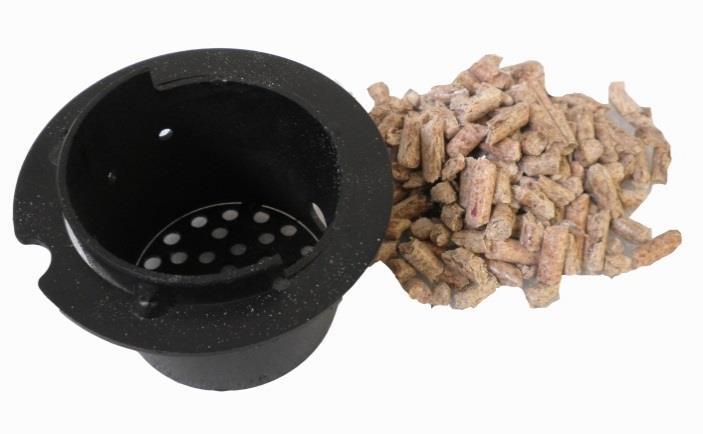
6 01. PRODUCT SAFETY 01.1 SAFETY WARNINGS The stoves were built in compliance according to standard EN13240 (wood stoves), EN (pellet stoves) and EN (kitchens and wood-burning stoves) using high quality and non-polluting materials. To make better use of your stove it is advisable to follow the instructions in this booklet. Read this manual carefully before use or any maintenance operation. Eva Stampaggi aims to provide as much information as possible to ensure safer use and to avoid damage to persons, property or parts of the stove itself. Each stove is subjected to internal testing before shipment and as such residues inside the appliance may be found. RETAIN THIS MANUAL FOR FUTURE REFERENCE. FOR ANY REQUIREMENT OR CLARIFICATION PLEASE CONTACT THE AUTHORISED RETAILER Installation and connection must be carried out by qualified staff in compliance with local regulations, national and European standards (UNI 10683) and with the annexed installation instructions. Furthermore, these operations must be performed by personnel who are authorised and professionally trained for the task in question. The combustion of waste, especially of plastic materials, damages the stove and the vent pipe. Moreover, it is forbidden by the law against the emission of harmful substances. Do not use alcohol, petrol or other highly inflammable liquids to light the fire or poke it during operation. Do not introduce into the stove an amount of fuel greater than that recommended in this booklet. Do not modify the product. It is forbidden to use the appliance with the door open or the glass broken. Do not use the appliance as, for example, a clothes drying rack, a bearing surface or step etc. Do not install the stove in bedrooms or bathrooms. The pellets to be used are the following: The pellet stoves operate exclusively with pellets made from various types of legislative-compliant wood. DIN plus or EN plus A1 or PEFC/ or ONORM M7135 or having the following characteristics: Min calorific value 4.8 kwh/kg (4180 kcal/kg) Density kg/m3 Maximum humidity 10% of the weight Diameter: 6 ±0.5 mm Percentage ash: max 1% of the weight Length: min 6 mm- max 30 mm Composition: 100% untreated wood from the industry of wood or post-consumption without the addition of binders, bark-free and compliant with current regulations. 5
7 01. PRODUCT SAFETY 01.2 GENERAL SAFETY PRECAUTIONS Use the stove only as described in this manual. Any other use not recommended by the manufacturer may cause fires or accidents to people. Make sure that the electrical power available corresponds to the value indicated on the data plate (220V~/50Hz). This appliance is not a toy. Make sure children are not left unattended and do not use the appliance as a toy. This device is not intended for use by persons (including children) with reduced physical or mental capacity, or without specific experience and knowledge, unless supervised or duly instructed on the use of the appliance by a person responsible for their safety. Disconnect the appliance from the mains when not in use or during cleaning operations. To do so, turn the switch to the O position and disconnect the plug from the socket. Pull the plug, not the cable. Never block the combustion air inlets and fume outlets. Since the stove is fitted with electrical components, do no touch it with wet hands. Do not use the appliance in case of damaged cables or plugs. The device is classified as type Y: the power supply cable may only be replaced by a qualified technician. Should the power supply cable be damaged, it can be replaced only by the manufacturer or by its technical assistance service or by a similarly qualified person. Do not place any object on the cable and do not bend it. Avoid using extension cables as their temperature may increase excessively posing fire hazards. Never use one single extension cable to power several appliances. During normal functioning some parts of the stove may become extremely hot, such as the door, the glass or the handle. Be careful, especially with children. Do not touch any hot parts if not wearing adequate protective devices. ATTENTION! DO NOT TOUCH the FIRE DOOR, the GLASS, the HANDLE or the FUME OUTLET DURING FUNCTIONING if not wearing adequate protective devices since they become extremely hot. Keep inflammable materials, such as furniture, cushions, pillows, blankets, paper, clothing, curtains, etc., at least 1.5 m away from the stove front and 30 cm from the stove sides and back. The stove that is covered by or in direct contact with inflammablematerials, including curtains, blankets, etc., during normal operation may result in a fire hazard. KEEP THE APPLIANCE AWAY FROM THE MATERIALS MENTIONED ABOVE. Do not immerse the cable, plug or any other appliance component in water or other liquids. Do not use the stove in dusty environments or wherever inflammable vapours are generated (e.g. in a workshop or garage). The stove is fitted with components that generate arcs and sparks. Do not install the stove in areas posing a significant fire or explosion hazard due to a high chemical substance concentration or to a high humidity level. Do not use the appliance close to bathtubs, showers, basins, sinks or swimming pools. Do not install the appliance underneath an air vent. Do not install the stove outdoors. Do not repair, disassemble or modify the appliance. The appliance is not fitted with components that can be repaired by users. Turn off the stove, disconnect it from the mains and wait until it has cooled down completely before performing any maintenance operations. WARNING: DISCONNECT THE STOVE FROM THE MAINS BEFORE PERFORMING MAINTENANCE OPERATIONS. ATTENTION! These stoves operate exclusively on pellets and possibly also pits if the stove has this option; DO NOT USE OTHER FUELS: any other material that may be burnt will result in failure and malfunction of the appliance. Keep the pellets in a fresh dry place: storing pellets in a place that is damp or excessively cold may reduce the stove potential heat output. Be careful when storing and handling pellet bags to prevent pellet crushing and consequent sawdust production. The fuel consists of small cylinders with 6-7mm diameter and a maximum length of 30mm. Their maximum moisture content is equal to 8%. This stove is designed to burn pellets made of compacted sawdust obtained from different types of wood, in compliance with environment protection legislation. The use of different types of pellets may result in a slight, sometimes even undetectable, change in the stove efficiency. This change can be counterbalanced by increasing or decreasing the stove heat output by only one step. Clean the burn pot on a regular basis upon every ignition or pellet refuelling. Open the firebox only upon refuelling or removal of residues to prevent fumes from escaping. Do not switch the stove on and off intermittently to avoid damaging its electrical and electronic components. 6
8 01. PRODUCT SAFETY Do not use the appliance as waste incinerator or for any other purpose other than the intended one. Do not use liquid fuels. Do not modify the appliance without prior authorisation. Use only original spare parts recommended by the manufacturer. Make sure that the stove is transported in compliance with safety regulations. Avoid any improper transfers or knocks that may damage the ceramics or the structure. The metal structure is coated using high temperature paints. When using the appliance for the first few times, unpleasant odours may be given off due to the paint of the metal parts that is drying: this is in no way dang erous and in such case, simply ventilate the premises. After the first heating cycles, the paint will reach its maximum adhesion and all its chemical and physical features. The reload the hopper, simply open the access lid and pour in the pellets, also during normal operation, making sure that no pellets fall out of it. Always refuel the hopper before leaving the operating stove unattended for long periods of time. Whenever the hopper and the Auger tube get completely empty, the appliance will be automatically switched off. It may take two separate ignitions to resume operation at ideal working conditions since the Auger tube is very long. ATTENTION! If the stove is not properly installed, power outages may result in fume spillages. Under specific circumstances, an uninterrupted power supply unit must be installed. ATTENTION! Being a heating appliance, some parts of the stove can become extremely hot. We therefore recommend paying special attention during operation. WHEN THE STOVE IS WORKING: o do not open the door; o do not touch the door glass since it becomes extremely hot; o keep children away from it; o do not touch the fume outlet; o do not pour any liquid inside the firebox; o do not perform any maintenance operations if the stove is not cold; o only qualified technicians are allowed to perform any operation; o follow all the instructions contained herein. Anti-explosion Some products are fitted with a safety device to prevent explosion. Before switching on the product or, in any case, after an y cleaning operation, make sure that the device is correctly positioned in its seat. The device is located on the firebox door upper edge. 7
9 01. PRODUCT SAFETY 01.3 EC CERTIFICATE OF CONFORMTY 8


10 02. PRODUCT DESCRIPTION The Hydro curved front 20/24 kw and the Hydro straight front 20/24 kw stoves They are tireless workers, we simply have to remember to feed them. Available in four power versions 20/24 kw. The essential lines and curved front means it is a stove that can be used as a furnishing item. The aspects of robustness, reliability, ease of use, the cast iron and steel interiors, the corten steel exchanger and the high yields result in a self-sufficient and durable appliance. In the 20/24 kw power versions using a particular kit called ACS it is also possible to heat domestic water. Hydro Kantina 20/24 kw Stove Thanks to the technology with which it was designed, this pellet-fuelled stove can be installed, resting it directly against the wall without leaving any gaps. Hydro Kantina is available in the 20 kw or 24 kw version, providing ample power to ensure optimal heating of rooms. The discharge can be upwards or to the rear, is fitted with remote control, daily programming and the possibility of operating according to the temperature of the water or the room. TECHNICAL DRAWING HYDRO CURVED FRONT 20/24 KW HYDRO STRAIGHT FRONT 20/24 KW 9
 Flue gas temperature Temperatura fumi ( C) Flue gas temperature at flue spigot or socket Temperatura uscita fumi ( C) Flue gas")
11 02. PRODUCT DESCRIPTION HYDRO KANTINA 20/24 KW STOVE TECHNICAL DATA Technical data of the appliance: Dati tecnici dell apparecchio: Designation: Designazione: Fuel throughput Consumo orario (kg/h) Necessary flue draught Requisiti minimi del tiraggio del camino (Pa) Flue gas temperature Temperatura fumi ( C) Flue gas temperature at flue spigot or socket Temperatura uscita fumi ( C) Flue gas mass flow Flusso massico dei fumi (g/s) Efficiency Rendimento (%) Total heating output Potenza termica (Kw) Water heating output Potenza termica resa all acqua (Kw) Space heating output Potenza termica resa all ambiente (Kw) CO emission at 13% of O2 Emissioni di CO al 13% di O2 (%) Maximum water operating pressure Massima pressione di esercizio dell acqua (bar) Discharge control operating temperature Temperatura di intervento termostato sicurezza acqua ( C) Electrical power supply Potenza elettrica assorbita (W) Rated voltage Tensione nominale (V) Rated frequency Frequenza nominale(hz) CURVED FRONT HYDRO 20 KW / STRAIGHT FRONTHYDRO 20 KW Nominal heat output Potenza termica nominale Reduced heat output Potenza termica ridotta CURVED FRONT HYDRO 24 KW / STRAIGHT FRONTHYDRO 24 KW Nominal heat output Potenza termica nominale Reduced heat output Potenza termica ridotta HYDRO KANTINA 20 KW HYDRO KANTINA 24 KW Nominal heat output Potenza termica nominale Reduced heat output Potenza termica ridotta Nominal heat output Potenza termica nominale Reduced heat output Potenza termica ridotta
 4 - Heating inlet 5 - Heating return")
12 02 PRODUCT DESCRIPTION 02.1 DESCRIPTION OF COMPONENTS 1 - Electronic pump 2 - Pressure transducer 3 - Safety valve (3bar) 4 - Heating inlet 5 - Heating return 6 - Expansion tank 7 - Fume motor 8 - Depressor 9 - Manual reset thermostat 10 - Automatic release valve 11
13 03 PRODUCT INSTALLATION 03.1 INTRODUCTION INSTALLATION WITH WALL FUME OUTLET IS PROHIBITED. INSTEAD THE FUME OUTLET MUST BE ROOF-TYPE AS PROVIDED FOR BY NATIONAL REGULATIONS. Eva Stampaggi S.r.l. declines any liability for any damage to persons or property arising from the failure to comply with the points mentioned above and from non-compliant product installation. Install the stove according to the regulations in force in the country of use. For example, in Italy this refers to UNI 10683: 2012, which dictates 4 points 1. preliminary activities - for which the retailer/installer is responsible and liable for at the time of the inspection before definitive installation The preliminary activities include: installation site suitability verification; fume evacuation system suitability verification; external air inlet suitability verification; At this stage it is necessary to check that the product can be safely operated and that it satisfies the relevant technical characteristics. The safety conditions must be ascertained by means of a prior inspection. Stoves and fireplaces are heating systems and must be installed safely and comply with the manufacturer's instructions! 2. Installation - responsibility of the installer. At this phase the aspects of installation of the product and of the fume evacuation system are taken into account and the following issues are addressed: safety distance from combustible materials; chimney flue construction, smoke ducts, intubated systems and chimney cowls. 3. issuing of additional documents - responsibility of the installer. Issuing of the technical documentation must include: manual of use and maintenance of the appliance and of the components of the system (e.g smoke ducts, chimney flue, etc.); Photocopy or photograph of the chimney flue plate; system manual: (if applicable); Declaration of Conformity in relation to Ministerial Decree 37/ control and maintenance - responsibility of the maintenance technician who must oversee protection and maintenance of the product during its operation over time. The operator in charge of control and maintenance of the systems for winter and summer climate control performs these activities to a professional standard in accordance with the regulations in force. The operator, at the end of these operations, must draw up and sign a technical inspection report in accordance with the models provided by the provisions of this decree and the implementing rules, in relation to the type and capacity of the system, to be issued to the person who signs a copy thereby confirming receipt and reading thereof." 03.2 VENT PIPE STOVE CHARACTERISTICS FOR SIZING OF THE VENT PIPE The curved front hydro 20 kw and the hydro straight front 20 kw stoves have the following characteristics: Chimney flue draught: 12 Pa Fume temperature: 154 C Mass flow of fumes: 10.8 g/s The curved front hydro 24 kw and the hydro straight front 24 kw stoves have the following characteristics: Chimney flue draught: 13 Pa Fume temperature: 179 C Mass flow of fumes: 14.3 g/s The kantina hydro 20 kw stoves have the following characteristics: Chimney flue draught: 13 Pa Fume temperature: 145 C Mass flow of fumes: 10.9 g/s The kantina hydro 24 kw stoves have the following characteristics: Chimney flue draught: 13 Pa Fume temperature: 164 C Mass flow of fumes: 13.2 g/s 12
14 03 PRODUCT INSTALLATION The vent pipe is one of the key features for guaranteeing the proper functioning of the stove. Thanks to the quality of the materials, the strength, the durability, the easy cleaning and maintenance, the best vent pipes are made of steel, either stainless steel or aluminised. The stove is fitted with a round fume outlet and a joint connection to be connected to the vent pipe. Use telescopic joint connections to facilitate connection to the steel rigid vent pipe and counterbalance the thermal expansion of both the firebox and the vent pipe. Seal the vent pipe joint connection with high temperature silicone sealant (1,000 C). Should the existing flue opening not be perfectly perpendicular to the firebox fume outlet, use an elbow to connect them. Inclination must never exceed 45, with respect to the vertical axis. No constrictions. Use 10cm-thick insulating thimbles if pipe vent passes through floors. The vent pipe must be insulated along its entire length. Thanks to the vent pipe, insulation fume temperature will remain high optimising draught, preventing condensation and reducing the build-up of non-ignited particles along the vent pipe walls. Use proper insulating materials (glass wool, ceramic fibre, Class A1 non-combustible materials). Install a vent pipe with a minimum vertical run of 2 mt to guarantee proper draught. The vent pipe must be weather-proof and as linear as possible. Flexible and length-adjustable metal pipes may not be used. 13

15 03. INSTALLING THE PRODUCT EXISTING VENT PIPE (TRADITIONAL) Types of vent pipe Examples of vent pipe Steel vent pipe with double chamber insulated with material resistant to 400 C. Optimum efficiency. Traditional clay vent pipe with cavities. Optimal efficiency. Refractory vent pipe with insulated double chamber and external coating in lightweight concrete. Optimal efficiency. Avoid vent pipes with internal rectangular section whose ratio between the larger and smaller side is greater than 1.5. Poor efficiency 14
16 03. INSTALLING THE PRODUCT 03.3 CHIMNEY COWL A properly installed chimney cowl ensures optimum stove functioning. The anti-downdraught chimney cowl consists of a number of components whose outlet section sum always doubles the vent pipe section. Make sure the chimney cowl is at least 150cm above the roof top so that it is fully exposed to the wind. The chimney cowls must: have useful outlet section that is at least twice that of the vent pipe. be made in such a way as to prevent the penetration of rain or snow. be constructed in such a way as to ensure, in the event of winds coming from any direction, the evacuation of combustion products. be free of mechanical intake auxiliaries. Roof pitch α [ ] Horizontal width of reflux zone measured from top A axis [m] Minimum height from roof for discharging exhaust fumes H min =Z+0.50m Height of reflux zone Z [m]

17 03. INSTALLING THE PRODUCT 03.4 DRAUGHT Fumes heat up during combustion, increasing their volume. Their density is therefore lower than the one of the surrounding colder air. This difference between the inside and outside temperatures of the chimney results in a negative pressure which increases proportionally to the vent pipe length and the temperature. The draught must be stronger than the fume circulation resistance so that all exhaust fumes generated during combustion inside the stove are drawn upwards through the outlet and the vent pipe. Many weather conditions affect the vent pipe functioning, such as rain, fog, snow, altitude, and wind being the most important since it can create both negative pressure and dynamic loading. The wind action varies depending on whether it is ascending, descending or horizontal. Ascending wind always results in an increased negative pressure and draught. Horizontal wind results in an increased negative pressure as long as the chimney cowl was properly installed. Descending wind always diminishes the negative pressure, sometimes inverting it. Excess draught causes an increase in the combustion temperature and consequently a loss in stove efficiency. A part of the combustion fumes are drawn up through the vent pipe together with small pellet particles before combustion reducing stove efficiency, increasing fuel consumption and resulting in the emission of polluting fumes. At the same time the high fuel temperature, due to an excess amount of oxygen, wears down the combustion chamber sooner than expected. On the other hand, poor draught slows down combustion resulting in a decrease in the stove temperature, fume spillage inside the room, a loss of stove efficiency and dangerous build-up in the vent pipe. In order to avoid excessive draught it is appropriate to use: Draught regulator 16
18 03. INSTALLING THE PRODUCT 03.5 STOVE EFFICIENCY Highly efficient stoves may pose difficulties for fume extraction. In order for a vent pipe to work properly its internal temperature must increase as a consequence of the fumes generated during combustion. Importantly, the efficiency of a heater is determined by its ability to transfer most of the heat produced to the environment to be heated: consequently, the greater the efficiency of the stove, the "colder" the residual fumes of combustion, and consequently, the lower the "draught". A traditional chimney flue, with a rough design and insulation, is more efficient if used with a traditional open fireplace o r a poor quality stove where most of the heat is lost with the fumes. Therefore, purchasing a quality stove often entails modifying the existing chimney flue to obtain a better insulation, even when it already works properly with old appliances. Poor draught results in the stove not operating when hot or in smoke spillage. Connecting the stove pipe to an existing chimney flue that has already been used with an old appliance is a common mistake. In this way two solid-fuel appliances share the same chimney flue, which is wrong and dangerous. If the two appliances are used simultaneously, the fume load might exceed the existing chimney flue capacity resulting in downdraught. If only one appliance is used, the fume heat will facilitate draught but the cold air coming from the other appliance not in use will cool down exhaust fume temperature again blocking the draught. Besides the problems described so far, if the two appliances are placed on different levels the communicating vessel principle might be interfered with, causing combustion fumes to be drawn in an irregular and unforeseeable way. 17
19 03. INSTALLING THE PRODUCT 03.6 INSTALLATION Using coaxial tubes the air will be pre-warmed contributing to improved combustion and lower emissions into the atmosphere. Follow the instructions before installing your stove. Select the position where the stove is to be installed and: Arrange the connection to the vent pipe for fume extraction. Arrange the external air intake (combustion air). Arrange the connection to the earthed mains. The electrical system of the room where the stove is to be installed must be earthed, otherwise the control board may not work properly. Place the stove on the floor in a convenient position for the connection to the vent pipe and close to the combustion air intake. The appliance must be installed on a floor with an adequate loading-bearing capacity. Should the existing floor not comply with the requirement above, proper measures must be taken (for instance, the installation of a load distribution plate). All the structures which can catch fire if exposed to excessive heat must be protected. Floors made from wood or inflammable materials must be protected using non-combustible materials (e.g. 4mm-thick sheet metal or ceramic glass). The appliance installation must ensure easy access for cleaning the stove, exhaust pipes and vent pipe. This appliance is not suitable to be installed on a shared vent pipe. During normal operation, the stove draws air from the room where it is installed. Therefore, an external air intake must be positioned at the same height of the pipe located on the stove back. Exhaust fume pipes must be suitable for pellet stoves and must therefore be made from coated steel or stainless steel, with a diameter of 8cm and fitted with adequate gaskets. 18
20 03. INSTALLING THE PRODUCT The combustion air intake (Φ 50mm) must be connected directly to the outside or to adjacent rooms provided they are fitted with external air supply vents (Φ 50mm) and are not used as bedrooms or bathrooms or, whenever a fire hazard exists, as storage rooms, garages, combustible material warehouses, etc. The air vents must be placed in such a way that they cannot be clogged either from the outside or inside and must be protected using a grille, a metal mesh or other suitable means provided they do not reduce the minimum section. If the stove is to be installed in rooms where it is surrounded by combustible materials (e.g. furniture, wood cladding, etc.), the following minimum clearances must be complied with: SAFETY DISTANCE FROM COMBUSTABLE MATERIALS: REAR WALL P = 200 mm SIDE WALL = 200 mm FLOORING F = 30 mm FRONT R = 1500 mm SAFETY DISTANCE FROM NON-FLAMMABLE MATERIALS: REAR WALL P = 100 mm SIDE WALL = 100 mm FLOORING F = 5 mm FRONT R = 1000 mm Besides complying with the minimum clearances set above, we also recommend installing heat-resistant fireproof insulating panels (rock wool, cellular concrete, etc.). The following is recommend: Promasil 1000 Classification temperature: 1000 C Density: 245 kg/m 3 Shrinkage at reference temperature, 12 h: 1000 C / 1.3% Cold crushing strength: 1.4 MPa Bending strength: 0.5 MPa Reversible thermal expansion: 5.4x10⁻⁶ m/mk Specific heat capacity: 1.03 Kj/kg K Thermal conductivity λ: 200 C 0.07 W/mK 400 C 0.10 W/mK 600 C 0.14 W/mK 800 C 0.17 W/mK Thickness: 40 mm When it is operational, the stove can cause a negative pressure in the room where it is installed. Therefore there should not be in the same room other naked flame devices, with the exception only of type c stoves (airtight). Make sure that the stove can draw the necessary quantity of combustion air: this must be from an open space (i.e. a space without exhaust blowers or providing adequate ventilation) or directly from outside. Do not install the stove in bedrooms or bathrooms. Unpack the stove: be careful not to damage the product at the time of unpacking. Check the stove's legs and adjust them so that the stove is stable. Place the stove so that the door and any window openings are not against the walls. After connecting the stove to the combustion air inlet join the coupling device to the vent pipe. 19
21 03. INSTALLING THE PRODUCT INSTALLATION EXAMPLE: EXAMPLE OF INCORRECT INSTALLATION: Exhaust pipes must never be fitted pointing downwards or horizontally so that fumes are discharged directly through the external wall. 20


22 03. INSTALLING THE PRODUCT CONNECTION EXAMPLES, SYSTEM DRAWINGS 21


23 03. INSTALLING THE PRODUCT 22
24 03. INSTALLING THE PRODUCT INSTALLATION In compliance with the current regulations for installation, the pellet thermo-stove should be installed in a ventilated place with air that is sufficient to ensure correct combustion and therefore good operation. The room must have a volumetry of no less than 20 m3 and to ensure good combustion (40 m3/h of air), there must be a combustion air intake" that must reach a wall that connects to the outside or to adjacent rooms provided they are fitted with external air supply vents (Ø80mm) and are not used as bedrooms or bathrooms or, whenever a fire hazard exists, as storage rooms, garages, combustible material warehouses, etc. These air vents must be placed in such a way that they cannot be clogged either from the outside or inside and must be protected using a grille, a metal mesh or other suitable means provided they do not reduce the minimum section. When it is operational, the thermo-stove can cause a negative pressure in the room where it is installed. Therefore there should not be in the same room other naked flame devices, with the exception only of type c stoves (watertight) unless they are fitted with their own air flow. They must not be positioned close to curtains, armchairs, furniture or to other flammable materials. They must not be installed in explosive or potentially explosive environments which may become explosive due to the presence of machinery, materials or dust that can cause greenhouse gas emissions or which can easily ignite with sparks. Before attempting to install the pellet thermo-stove, bear in mind that all fixtures or any beams made of combustible material must be placed at a safe distance and outside the radiation area of the stove itself. Also consider that in order not to compromise the correct operation of the appliance, it is essential to create air circulation inside its casing. This helps prevent overheating and can be achieved by respecting the minimum distances and by creating a number of ventilation holes. Internally, the thermo-stove is equipped with all the components for safety: automatic ventilating valve, 3-bar safety valve, expansion tank and stove safety thermostat. Remember to discharge the hydraulic system before switching on the appliance. The use of hosing is recommended that connects the appliance to the hydraulic system as, in the case of ordinary or extraordinary maintenance, this makes it easy to move. It is also recommended to install a dirt separator as the electronic pump could capture the dirt of the system and become jammed. ELECTRICAL CONNECTION The electrical connection must be performed by qualified personnel who install circuit breakers upstream of the appliance. Extra attention we need to do when the stove are an integration to the plant and all the machines have to work like the program. Avoid installations with electric cables that run close to fume pipes or hot components that are suitably insulated. The voltage is 230 V while the frequency is 50 Hz. The electrical system where it is connected must be fitted with a conductor as required by the Regulations 73/23 EEC and 93/98 EEC. EXTERNAL THERMOSTAT In these thermo-stoves it is possible to install an external thermostat. This operation may only be performed by authorised personnel. Use a 2-pole cable with everyday double insulation. In the event that the thermostat is closed, the stove functions at the power set. If the thermostat opened, the stove would work in MODULATE mode until the thermostat closes. First connect the stove plug to the mains and load the pellet hopper. Be careful not to empty the entire bag at once. Perform this operation slowly. 23

25 04. PRODUCT USE 04.1 ELECTRONICS WITH 6-BUTTON LCD DISPLAY Proper functioning and control adjustment devices Control panel The control panel shows the information concerning the stove status. Several types of data can be displayed and the settings available according to the access level can be modified by entering the menu. Depending on the selected mode and on their position on the display, the data visualised may acquire different meanings. figure 2 shows an example with the stove switched off or on. fig.2 figure 3 describes the meaning of the status indicators that appear on the left side of the display. When one of the devices included in the list is activated, the relevant segment on the display status area switches on. Fig.3 Fig. 4. figure 4 describes the position of the messages displayed during programming or setting of the operating parameters. In particular: 1.The input area shows the entered programming values 2.The menu level area displays the current menu level. See chapter dedicated to menu. 24

26 04. PRODUCT USE Description of Panel BUTTON 1 (P1) - Temperature increase: When in programming mode, use this button to modify/increase the selected menu value. When in working mode/switched off, use instead this button to increase the stove temperature value. BUTTON 2 (P2) - Temperature decrease: When in programming mode, use this button to modify/decrease the selected menu value. When in working mode/switched off, use instead this button to decrease the room thermostat temperature value. mode. BUTTON 3 (P3) - Set/menu: Use this button to access temperature setting and user and technician parameter menu. After entering the menu, use this button to access the next sub-menu or set the value and move to the next menu item when in programming BUTTON 4 (P4) - ON/OFF Release: Hold this button down for two seconds to manually switch the stove on or off respectively depending on its initial status (switched on or off). Should have any alarm blocked the stove, press this button to unlock it and subsequently switch it off. After entering the menu or during the programming phase, use this button to access the upper menu level. Any change is automatically saved BUTTON 5 (P5) - Heat output decrease: When in working mode, use this button to decrease the heat output value. In menu mode, use this button to move to the next menu item or, in programming mode, to go back to the subsequent sub-menu item. Any change is automatically saved. BUTTON 6 (P6) - Heat output increase: When in working mode, use this button to modify the exchanger speed. In menu mode, use this button to go back to the previous menu item or, in programming mode, to go back to the previous sub-menu item. Any change is automatically saved. The menu Press the P3 (MENU) button to access the menu. It includes several items and levels to access settings and control board programming. The menu items providing access to the technical setting are protected by access code. User menu The table below briefly describes the menu structure, focusing in particular on the functions available to users. The menu item 01-fan adjustment is only available if the corresponding function has been enabled. 25
27 04. PRODUCT USE Level 1 Level 2 Level 3 Level 4 Value 01 - time clock setting 01 - day Week day 02 - hours Hour 03 - minutes Minute 04 - day day month 05 - month Month 06 - year Year 02 chrono setting 01 - enable chrono 01 - enable chrono On/off 02 day programming 01 day chrono On/off 02 - start 1 day Hour 03 - stop 1 day Hour 04 - start 2 day Hour 05 - stop 2 day Hour 03 week programming 01 week chrono On/off 02 - start prog 1 Hour 03 - stop prog 1 Hour 04 - Monday prog 1 On/off 05 - Tuesday prog 1 On/off 06 - Wednesday prog 1 On/off 07 - Thursday prog 1 On/off 08 - Friday prog 1 On/off 09 - Saturday prog 1 On/off 10 - Sunday prog 1 On/off 11 - start prog 2 Hour 12 - stop prog 2 Hour 13 - Monday prog 2 On/off 14 - Tuesday prog 2 On/off 15 - Wednesday prog 2 On/off 16 - Thursday prog 2 On/off 17 - Friday prog 2 On/off 18 - Saturday prog 2 On/off 19 - Sunday prog 2 On/off 20 - start prog 3 Hour 21 - stop prog 3 Hour 22 - Monday prog 3 On/off 23 - Tuesday prog 3 On/off 24 - Wednesday prog 3 On/off 25 - Thursday prog 3 On/off 26 - Friday prog 3 On/off 27 - Saturday prog 3 On/off 28 - Sunday prog 3 On/off 26
28 04. PRODUCT USE Level 1 Level 2 Level 3 Level 4 Value 29 - start prog 4 Hour 30 - stop prog 4 Hour 31 - Monday prog 4 On/off 32 - Tuesday prog 4 On/off 33 - Wednesday prog 4 On/off 34 - Thursday prog 4 On/off 35 - Friday prog 4 On/off 36 - Saturday prog 4 On/off 37 - Sunday prog 4 On/off 04 - week-end program 01 - week-end chrono 02 - start stop start stop 2 03 select language 01 - Italian Set 02 - French Set 03 - English Set 04 - German Set 04 - stand-by mode On/off 05 - buzzer On/off 06 initial load Set 07 stove status - 27
29 04. PRODUCT USE Menu 01 - time clock setting Use this function to set current time and date. The control board is equipped with a lithium battery guaranteeing the internal time clock a 3/5 year-long life. Menu 02 chrono setting Sub-menu enabling chrono The programmable thermostat functions can be disabled and enabled. Sub-menu daily program The daily programmable thermostat functions can be enabled, disabled and set. It is possible to set two on/off times defined by the times set according to the table below. If the value is set to OFF, the time clock ignores the control. Selection Meaning Available values START 1 switching-on time time - OFF STOP 1 switching-off time time - OFF START 2 switching-on time time - OFF STOP 2 switching-off time time - OFF 28

30 04. PRODUCT USE Sub-menu weekly programme The weekly programmable thermostat functions can be enabled, disabled and set. The weekly programmer consists of 4 independent programmes which can be combined together in different ways. The weekly programmer can be enabled or disabled. Moreover, if the time is set to OFF, the time clock ignores the corresponding control. Attention: set the programming carefully in order to avoid overlapping of switching on and/or off times of different programmes on the same day. PROGRAMME 1 menu level setting meaning available values START PROG 1 switching-on time time - OFF STOP PROG 1 switching-off time time - OFF MONDAY PROG 1 on/off TUESDAY PROG 1 on/off WEDNESDAY PROG 1 on/off THURSDAY PROG 1 on/off FRIDAY PROG 1 on/off SATURDAY PROG 1 on/off SUNDAY PROG 1 on/off PROGRAMME 2 menu level setting meaning available values START PROG 2 switching-on time time - OFF STOP PROG 2 switching-off time time - OFF MONDAY PROG 2 on/off TUESDAY PROG 2 on/off WEDNESDAY PROG 2 on/off THURSDAY PROG 2 on/off FRIDAY PROG 2 on/off SATURDAY PROG 2 on/off reference day reference day SUNDAY PROG 2 on/off PROGRAMME 3 menu level setting meaning available values START PROG 3 switching-on time time - OFF STOP PROG 3 switching-off time time - OFF MONDAY PROG 3 on/off TUESDAY PROG 3 on/off WEDNESDAY PROG 3 on/off THURSDAY PROG 3 on/off FRIDAY PROG 3 on/off SATURDAY PROG 3 on/off reference day SUNDAY PROG 3 on/off 29

31 04. PRODUCT USE PROGRAMME 4 menu level setting meaning available values START PROG 4 switching-on time time - OFF STOP PROG 4 switching-off time time - OFF MONDAY PROG 4 on/off TUESDAY PROG 4 on/off WEDNESDAY PROG 4 on/off THURSDAY PROG 4 on/off FRIDAY PROG 4 on/off SATURDAY PROG 4 on/off SUNDAY PROG 4 on/off Sub-menu week-end program The programmable thermostat functions can be enabled, disabled and set for the week-end (days 5 and 6, or Saturday and Sunday). reference day SUGGESTION: if you still do not know exactly the result you want to obtain, enable only one programme at a time to avoid confusion and unwanted stove switching on and off. Disable the daily programme if you want to use the weekly programme. If you use the weekly programme for 1, 2, 3 and 4 programmes, never enable the week-end programme. Always disable the weekly programme before enabling the week-end programme. Menu 03 select language Use this function to select one of the languages available. 30

32 04. PRODUCT USE Menu 04 - stand-by-mode - activate mode 2 If you select the STAND-BY mode, the stove switches off after a period of time, set by Pr44, during which the room temperature remains at a value higher than the SET temperature. Only if the following condition occurs it is then possible to switch the stove back on: TSET < (Tstove-Pr43) FOR THE INSTALLER: There are 3 standby modes: Mode 1 WITH RESPECT TO THE AMBIENT SENSOR AND THE TEMPERATURE OF THE WATER Having set the water temperature, commence operation of the stove. 1 - With the environment set reached the stove goes into stand by. 2 - With the air set not reached the stove is operational Nearing Set Water, the stove goes into modulation and remains in modulation. Only go into stand by when air Set has been reached. It comes on again with a value below air Set. The AMBIENT SENSOR takes priority Mode 2: WITH RESPECT ONLY TO THE WATER TEMPERATURE Having set the water temperature, commence operation of the stove. Nearing the Water Set, the stove goes into modulation and when the Set is exceeded, modulation and then stand by are enabled. Below Set the stove comes on again and resumes operation. The stove in no way considers the temperature measured by the ambient sensor of the same stove. The WATER TAKES PRIORITY Mode 3: WITH RESPECT TO THE THERMOSTAT AND TO THE TEMPERATURE OF THE WATER Having set the water temperature, commence operation of the stove. 1 - With thermostat open the stove goes into modulation and then stand by 2 - With thermostat closed the stove is operational Nearing Set Water, the stove goes into modulation and remains in modulation. It only goes into stand by mode when the thermostat opens the contact. It turns on when the thermostat closes the contact. The stove in no way considers the temperature measured by the ambient sensor of the same stove. The THERMOSTAT TAKES PRIORITY Menu 05 - buzzer mode Set it to OFF to disable the buzzer. Menu 06 initial load This function is important if the stove is new or if the stove is off due to the absence of pellets in the hopper. INITIAL IGNITION MUST BE PERFORMED BY AUTHORISED PERSONNEL ONLY NOT BY THE PURCHASER. CONTACT THE SERVICE CENTER THAT WILL SEND OUT A SPECIALIST TECHNICIAN TO YOU. Use this function to pre-load pellets for a period of 90 seconds when the stove is switched off and cold. Press P1 button to start and P4 button to stop. 31


33 04. PRODUCT USE Menu 07 stove status This function displays the current status of all the devices connected to the stove. A few examples are included in the following pages. page 3 page 2 page 1 32

34 04. PRODUCT USE User functions Standard functioning of a control board properly installed on a forced air pellet stove is described below with reference to the functions available to users. The indications listed below refer to a control board fitted with programmable thermostat. Before switching on the stove, the display is as in figure 16. fig. 16 Stove ignition Make sure that there are pellets in the hopper, that the burn pot is correctly positioned and clean from any combustion residues and then close the door. Hold down P4 for a few seconds to switch on the stove. The display shows that the stove is on. Start-up phase The stove performs all the steps of the start-up phase according to the parameters concerning its levels and times. The display will show the wording ON, as there is no pellet loading but the fume fan is operating. PELLET LOADING state will occur where the pellets are being loaded into the burn pot. Once the pellets have started to burn and the fume temperature is increased, the display will show FIRE ON, a transition phase between ignition and operating power. Ignition failure The alarm is triggered when, after the period of time set by Pr01, the fume temperature has not reached the minimum value permitted (Pr13 parameter) with a gradient equal to 2 C/min. If there are unburned pellets inside the burn pot, it is necessary to empty the burn put before switching on the stove again. This will avoid wasted pellets and possible spillage within the combustion chamber. If the pellets have begun to burn but the alarm state persists, wait until all the pellets are burning and then switch on again. Check that there are pellets inside the hopper. Stove operational. At the end of the start-up phase, if no problems occurred, the stove enters its normal working mode. If the temperature of the stove is the same as that set, the pump will come on. Changing set room temperature Press the P2 button to change the set room temperature. The display shows the current SET temperature state as in figure 19. fig
35 04. PRODUCT USE Changing set stove temperature Press P1 button to change the set room temperature. The display shows the current SET temperature value. External thermostat/chronothermostat use If you want to use an external programmable thermostat, connect it to the TERM clamps (connector CN7 pin 7-8). external thermostat: external chronothermostat: The stove external thermostat is enabled when the contact is closed with stove on. Room temperature reaches the set value (SET temperature) When the set room temperature value is reached or the fume temperature has reached the Pr13 value, the stove heat output is set automatically to the minimum value (MODULATION mode). See figure 20 fig. 20 If the stove is in the STAND-BY mode, it switches off after the period of time set by Pr44 and after reaching the SET temperature. Reignition occurs after occurrence of the following condition: Tambient > (TSET + Pr43) The same situation is achieved and the stove temperature reaches that set. The modulation status is evident and, if enabled, STANDBY status. Cleaning of the burn pot. When the stove is in the working mode, the BURN POT CLEANING mode is activated for the period set by Pr12 parameter at the intervals set by Pr03 parameter. fig. 21 Stove switch off Hold down P4 button for approx. 2 seconds to switch off the stove. The Auger tube stops immediately and the exhaust blower reaches its maximum speed value. The FINAL CLEANING phase is performed. At the end of the period of time set by Pr39, when the fume temperature has reached a value below Pr13 parameter, the exhaust blower stops. 34

36 04. PRODUCT USE Stove switched off The display will show the wording OFF. The fume fan stops working. Stove re-ignition It will be possible to switch the stove back on only at the end of the safety period of time set by Pr38 and if the fume temperature has reached a value below Pr13. What happens in case of... Pellet ignition failure If the pellets do not ignite, the display shows the alarm message NO ACC as shown in figure 25. black-out fig. 25 Pr48 = 0 When the power is resumed after an outage, the stove enters the FINAL CLEANING phase and waits until the fume temperature reaches a value below Pr13. fig. 26 Pr48 = T seconds After a power outage, one of the following conditions may occur depending on the stove previous status: previous status black-out duration new status switched off any switched off ignition < T ignition pellet loading without pre-load < T pellet loading pellet loading with pre-load any switching off waiting for flame < T waiting for flame working mode < T working mode burn pot cleaning < T burn pot cleaning switching off < T switching off If the power outage duration is longer than T, the stove switches off. 35
37 04. PRODUCT USE Alarms In case of malfunctioning the control board reports the problem and activates various procedures depending on the type of alarm. Possible alarm messages are listed below. Cause Display shows Fume temperature sensor ALARM FUME SENSOR Fume overheating ALARM HOT TEMP Ignition failure ALARM NO FIRE Switches off when in working mode ALARM NO FIRE Power outage COOL FIRE (see sect. 9.2) Auger tube safety pressure switch ALARM PRESS FAIL General safety thermostat ALARM SAFETY FAIL Damaged exhaust blower ALARM FAN FAIL In case of alarm, the stove is immediately switched off. The alarm status is reached after a set period of time (Pr11) and can be cleared by pressing the P4 button. Fume temperature sensor alarm The alarm is triggered when the fume temperature sensor is not working properly or is disconnected. During the alarm, the stove switches off. fig. 27 Fume overtemperature alarm The alarm is triggered when the fume sensor identifies a temperature exceeding 280 C. The message shown in figure 28 appears. fig. 28 The stove switching-off phase starts immediately. Ignition failure alarm The alarm is triggered whenever ignition fails. The stove switching-off phase starts immediately. fig

38 04. PRODUCT USE Stove switching-off during working mode alarm If during normal working mode, the flame goes out and the fume temperature falls below the minimum threshold (Pr13 parameter), the alarm is activated as shown in figure 30. The stove switching-off phase starts immediately. Auger tube safety pressure switch alarm. fig. 30 If the pressure switch (pressure meter) detects a value below the trigger threshold, it immediately switches off the Auger tube (to which it is connected in series) while the control board acquires this change in status through the AL2 clamp in CN4. The message Alarm Dep Fail appears on the display and the stove is immediately switched off. fig. 31 General thermostat alarm If the general safety thermostat detects a value exceeding the trigger threshold, it immediately switches off the Auger tube (to which it is connected in series), while the control board acquires this change in status through the AL1 clamp in CN4. The message "ALARM SEC FAIL" is displayed and the system shuts down. Unscrew the black cap behind the stove and press the button to reset the contact. Damage exhaust blower alarm fig. 32 Whenever the exhaust blower stops working properly, the stove switches off immediately and the message ALARM FAN FAIL appears on the display.the stove switching off phase starts immediately. fig

39 04. PRODUCT USE Connections 38

40 05. CLEANING AND MAINTENANCE 05.1 INTRODUCTION The stove requires a simple yet constant cleaning to guarantee top efficiency and proper functioning. Constant maintenance by a qualified technician is recommended. The stove should be cleaned before the cold season because it can sometimes get clogged during the summer (by nests for example) preventing exhaust fumes to flow regularly. At the beginning of the season and in case of wind, a build-up of residue in the pipe may lead to fires. Should this happen, find below a few pieces of advice to follow: Block air supply to the pipe immediately; Throw sand or kitchen salt, and not water, to extinguish fire and coals; Keep objects and furniture away from the burning pipe. ALSO TO PREVENT THIS TYPE OF FAULT YEARLY CLEANING OF THE VENT PIPE IS ESSENTIAL, REMOVING DEPOSITS OR ANY POCKETS OR OBSTRUCTIONS. ATTENTION: USE A DRY CLOTH TO CLEAN THE STOVE EXTERNALLY THE AUGER TUBE MUST BE COMPLETELY EMPTIED FROM PELLETS WHEN USING THE STOVE FOR THE LAST TIME AT THE END OF THE SEASON. THE AUGER TUBE MUST REMAIN EMPTY TO PREVENT IT FROM GET CLOGGED BY SAWDUST RESIDUES SOLIDIFIED DUE TO MOISTURE DAILY CLEANING Any cleaning operation must be performed when the stove is completely cold: Empty the ash drawer: vacuum it out or dispose of the ashes in a waste bin. Vacuum the combustion chamber: check that there are no embers that may still be lit. In this case your ash vacuum cleaner will catch fire. Remove the ash inside firebox and on door. Wipe the glass with a damp cloth or a damp ball of newspaper dipped into the ash. If the operation is performed with the stove hot there is a risk of the glass exploding. ATTENTION: USE A DRY CLOTH TO CLEAN THE STOVE EXTERNALLY DO NOT USE ABRASIVE MATERIALS OR PRODUCTS THAT MAY CORRODE OR LIGHTEN THE SURFACES MANUFACTUTER LIABILITY The manufacturer shall not be held liable against any direct and/or indirect, criminal and/or third party liability arising from: failure to abide by the instructions contained herein. non authorised repair operations or changes. use not compliant with safety rules. installation not compliant with national current regulations and safety rules. insufficient maintenance; the use of spare parts that are not original or which are not specific to the model. 39
INSTRUCTION MANUAL PELLET STOVES PELLET STOVE EV 14 - EV 20 - EV 24 - EV 34
 EN INSTRUCTION MANUAL PELLET STOVES PELLET STOVE EV 14 - EV 20 - EV 24 - EV 34 IMPORTANT: ESSENTIAL TO READ 1. The warranty is valid if INITIAL IGNITION is performed by an AUTHORISED TECHNICIAN. 2. Do
INSTRUCTION MANUAL PELLET INSERTS 7.5 KW 11 KW
 EN INSTRUCTION MANUAL PELLET INSERTS 7.5 KW 11 KW IMPORTANT: ESSENTIAL TO READ 1. The warranty is valid only if the FIRST IGNITION is carried out by an AUTHORISED TECHNICIAN. 2. DO NOT TURN THE PRODUCT
PELLET STOVES INSTRUCTION MANUAL
 EN PELLET STOVES INSTRUCTION MANUAL MAJOLICA LINE PELLET LINE SLIM LINE IMPORTANT: READ THE FOLLOWING INFORMATION 1. The warranty is valid only if the FIRST IGNITION is carried out by an AUTHORISED TECHNICIAN.
INSTRUCTION MANUAL WOOD STOVES 8.5KW
 EN INSTRUCTION MANUAL WOOD STOVES 8KW 8.5KW 12.5KW CONTENTS 01. SAFETY WARNINGS... 2 02. GENERAL SAFETY PRECAUTIONS... 3 03. VENT PIPE... 5 04 CHIMNEY COWL... 8 05. DRAUGHT... 9 06. STOVE EFFICIENCY...
INSTRUCTION MANUAL WOOD-BURNING STOVES TC 60 TC 100
 EN INSTRUCTION MANUAL WOOD-BURNING STOVES TC 60 TC 100 TABLE OF CONTENTS 01. PRODUCT SAFETY... 2 01.1 SAFETY WARNINGS... 2 01.2 GENERAL SAFETY PRECAUTIONS... 4 01.3 EC CERTIFICATE OF CONFORMITY... 5 02.
USER MANUAL 9kW LILLY PELLET STOVE
 USER MANUAL 9kW LILLY PELLET STOVE Table of Contents.Overview of Stove Parts... 2.Technical Characteristics... 3 3.Important Information... 4 4.Pellet Specification...5 5.Technology... 6 6.Installation...
CentroPelet ZV14 TECHNICAL INSTRUCTIONS HEATING TECHNIQUE. for regulation, use and maintenance of pellet stove
 HEATING TECHNIQUE Centrometal d.o.o. - Glavna 12, 40306 Macinec, Croatia, tel: +385 40 372 600, fax: +385 40 372 611 TECHNICAL INSTRUCTIONS for regulation, use and maintenance of pellet stove CentroPelet
GUIDE BOOK MAINTENANCE
 1 di 12 10/10/29 10.48 Thermostoves PELLET Edition February 24 Page 1 of 12 GUIDE BOOK MAINTENANCE 2 di 12 10/10/29 10.48 Dear Customer, thanks for the confidence concessaci purchasing a pellet stoves
LISEO Insert. European Standard Certification UNE EN inserts. LISEO s.r.o. Folknářská 1246/21 Děčín 2 Nové Město
 LISEO Insert European Standard Certification UNE EN-13229 inserts LISEO s.r.o. Folknářská 1246/21 Děčín 2 Nové Město 405 02 INTRODUCTION.4 1. GUARANTEE CONDITIONS.4 1.1. SAFETY WARNINGS....4 1.2. GUARANTEE
LISEO STOVES. European Standard Certification UNE EN stoves. LISEO s.r.o. Folknářská 1246/21 Děčín 2 Nové Město
 LISEO STOVES European Standard Certification UNE EN-13240 stoves LISEO s.r.o. Folknářská 1246/21 Děčín 2 Nové Město 405 02 INTRODUCTION.3 2 1. GUARANTEE CONDITIONS.3 1.1. SAFETY WARNINGS..3 1.2. GUARANTEE
USE AND MAINTENANCE INSTRUCTIONS PELLET STOVE. Air Channelled Air Hydro Boilers
 USE AND MAINTENANCE INSTRUCTIONS PELLET STOVE Air Channelled Air Hydro Boilers Read instructions carefully before installation, use and maintenance. The instructions manual is an integral part of the product.
.it AQ USER OPERATING INSTRUCTIONS
 .it AQ 15 USER OPERATING INSTRUCTIONS Dear Customer, In congratulating you for purchasing one of our heat stoves, we would like to remind you that pellet heat stoves are the most innovative heating solution,
INSTALLATION AND USER S MANUAL COOKER HOOD RS-600/A-S
 INSTALLATION AND USER S MANUAL COOKER HOOD RS-600/A-S RS-600 (CHS60SS)-GB-05.indd 1 6/8/2010 9:30:59 AM TABLE OF CONTENTS 1. Introduction 2 2. Safety precaution 2 3. Intended use 3 4. Parts supplied 3
Rocket heater GAMERA
 Rocket heater GAMERA High efficiency heater on hard fuel Manufacturer: AGNON Ltd., Bulgaria Hissarya, 4 Han Kubrat STR. +359 885 525 464 WWW.GAMERA.EU ROCKETGAMERA@GMAIL.COM ATTENTION! Read the following
pellet stoves USER MANUAL LED
 pellet stoves USER MANUAL LED /INGLESE Applicare etichetta dati technici 2 ATTENTION SURFACES CAN BECOME VERY HOT! ALWAYS USE PROTECTIVE GLOVES! During combustion, thermal energy is released that significantly
NOVELLA EVO - NOVELLA PLUS EVO MADE IN ITALY. design & production Rev 001
 UK MADE IN ITALY design & production pellet stoves USER MANUAL NOVELLA EVO - NOVELLA PLUS EVO 00476699 - Rev 001 ENGLISH ATTENTION SURFACES CAN BECOME VERY HOT! ALWAYS USE PROTECTIVE GLOVES! During combustion,
pellet stoves USER MANUAL diadema idro - liliana idro MADE IN ITALY design & production Rev 003
 MADE IN ITALY design & production 004276528 - Rev 003 pellet stoves USER MANUAL diadema idro - liliana idro /INGLESE 2 ATTENTION SURFACES CAN BECOME VERY HOT! ALWAYS USE PROTECTIVE GLOVES! During combustion,
INSTALLATION AND OPERATING INSTRUCTIONS BIOCLASS HM
 INSTALLATION AND OPERATING INSTRUCTIONS BIOCLASS HM Thank you for choosing a DOMUSA TEKNIK heating boiler. Within the product range offered by DOMUSA TEKNIK you have chosen BioClass HM model. With a suitable
TIH 300 S / TIH 400 S / TIH 500 S / TIH 700 S / TIH 900 S / TIH 1100 S
 TIH 300 S / TIH 400 S / TIH 500 S / TIH 700 S / TIH 900 S / TIH 1100 S EN OPERATING MANUAL INFRARED HEATING PANEL TRT-BA-TIH300S-TIH400S-TIH500S-TIH700S-TIH900S-TIH1100S-TC-002-EN Table of contents Notes
pellet stoves USER MANUAL Comfort P70 & P70 h49
 pellet stoves USER MANUAL Comfort P70 & P70 h49 /INGLESE ... 4 Warnings... 4 Safety... 4 Routine Maintenance... 4 INSTALLATION... 5 General... 5 COMFORT P70/ P70H49 INSTALLATION... 7 minimum dimensions...
COMPACT COMPACT 24
 INSTALLATION AND USER GUIDE EN PELLET BOILER COMPACT 18-2015 COMPACT 24 HYDRO MODEL Translation of original instructions TABLE OF CONTENTS TABLE OF CONTENTS... II INTRODUCTION... 1 1-WARNINGS AND WARRANTY
STILE BEAUTY AND TECHNOLOGY
 STILE BEAUTY AND TECHNOLOGY STILE, in line with your style Designer White Bordeaux Silver Grey MODEL Nominal input kw Nominal output kw Output to the water min. / max. kw HYDRONIC PELLET FIRE SPACE HEATING
pellet stoves USER MANUAL LED
 pellet stoves USER MANUAL LED /INGLESE 2 ...4 Warnings... 4 Safety... 4 Routine Maintenance... 4 INSTALLATION... General... INSTALLING COMFORT MAXI/ COMFORT PLUS... 7 Assembly with sliding base...7 Comfort
Comfort P70 - Comfort P70 H49 MADE IN ITALY. design & production Rev 003
 UK MADE IN ITALY design & production pellet stoves USER MANUAL Comfort P70 - Comfort P70 H49 00476731 - Rev 003 ATTENTION SURFACES CAN BECOME VERY HOT! ALWAYS USE PROTECTIVE GLOVES! During combustion,
pellet stoves USER MANUAL lcd
 pellet stoves USER MANUAL lcd /INGLESE ...4 Warnings... 4 Safety... 4 Routine Maintenance... 4 INSTALLATION... 5 General... 5 SOUVENIR and ILENIA - ANNABELLA spacers... 7 HOT AIR DUCTING... 7 SOUVENIR
GENERAL RULES. Ensure that the installation of your product conforms to all the indications given below. English CHIMNEY STACK
 1.0 GENERAL RULES DT2010216-05 Ensure that the installation of your product conforms to all the indications given below. Fig. 1 CHIMNEY STACK SINGLE FLUEWAY OR CHIMNEY CONNECTION TO FLUE SOOT INSPECTION
CERAMIC TOWER FAN HEATER PL2000
 CERAMIC TOWER FAN HEATER PL2000 Instruction Manual Due to ongoing product improvements, specifications and accessories may change without notice. Actual product may differ slightly to that depicted. CONTENTS
THERMO PRODUCTS USER MANUAL. diadema idro - liliana idro MADE IN ITALY. design & production Rev 008
 UK MADE IN ITALY design & production THERMO PRODUCTS USER MANUAL diadema idro - liliana idro 004276528 - Rev 008 2 ATTENTION SURFACES CAN BECOME VERY HOT! ALWAYS USE PROTECTIVE GLOVES! During combustion,
WHE 2.24 / WHE 2.24 FF
 EN Wall-hung gas boilers WHE 2.24 WHE 2.24 FF User Guide 300011777-001-C . Contents 1 Introduction.............................................................................3 1.1 Symbols used...........................................................................................3
Instructions for use
 Instructions for use These instructions are also available on the website: www.kitchenaid.eu Important instructions for safety 4 Installation 6 Safeguarding the environment 6 Troubleshooting guide 7 After-sales
Pellet insert FIRE PLACE 22 INSTALLATION, USE AND MAINTENANCE, USEFUL TIPS ENGLISH
 ENGLISH Pellet insert stove PELLET FIRE PLACE 22 INSTALLATION, USE AND MAINTENANCE, USEFUL TIPS SERVICE DECLARATION Ref. Annex III EU Regulation no. 305/2011 DoP/KLOVER-010 1. Identification number :
ENGLISH DIVA Pellet boiler stove
 ENGLISH DIVA Pellet boiler stove INSTALLATION, USE AND MAINTENANCE, USEFUL TIPS SERVICE DECLARATION Ref. Annex III EU Regulation no. 305/2011 DoP/KLOVER-014 1. Identification number : DV 2. Model and/or
ENGLISH DIVA Pellet boiler stove
 ENGLISH DIVA Pellet boiler stove INSTALLATION, USE AND MAINTENANCE, USEFUL TIPS SERVICE DECLARATION Ref. Annex III EU Regulation no. 305/2011 DoP/KLOVER-014 1. Identification number : DV 2. Model and/or
BIX B-One 100 kw INSTALLATION GUIDE
 BIX B-One 100 kw INSTALLATION GUIDE Dear Customer, We thank you for choosing our product. The Bix B-One 100 Kw is a burner of advanced concept and technology, with a high reliability and construction quality.
Heating, Air Conditioning, Ventilation. Отопление-Кондиционеры-Вентиляция. MTM 8-30 kw UNIVERSAL OIL HEATER OPERATING MANUAL
 Heating, Air Conditioning, Ventilation Отопление-Кондиционеры-Вентиляция MTM 8-30 kw UNIVERSAL OIL HEATER OPERATING MANUAL 1. Usage MTM 8-30 universal oil heater is designed for heating commercial rooms
INSTRUCTIONS FOR ASSEMBLY, USE, AND MAINTENANCE PELLET STOVE LUCA S/LUKA S8
 WARNING: This user manual is an integral part of the product. It has to be kept and read carefully. EN INSTRUCTIONS FOR ASSEMBLY, USE, AND MAINTENANCE PELLET STOVE LUCA S/LUKA S8 1. Introduction Firstly,
INSTRUCTIONS FOR INSTALLATION AND MANUAL Solid fuel stove for central heating THERMO IN
 INSTRUCTIONS FOR INSTALLATION AND MANUAL Solid fuel stove for central heating THERMO IN To respected customer, We are very pleased for your trust and your decision to buy our product. You made a good choice,
INSTRUCTIONS FOR USE. To make the most of your new oven, read the user's instructions carefully and keep them on hand for consultation in the future.
 INSTRUCTIONS FOR USE INSTALLATION...4 SAFEGUARDING THE ENVIRONMENT... 7 IMPORTANT NOTES... 7 BEFORE USING THE OVEN... 8 OVEN ACCESSORIES... 9 CARE AND MAINTENANCE... 10 TROUBLESHOOTING GUIDE... 12 AFTER
So old fashioned... As the combustion chamber is completely room sealed, it does not release any smells and does not dirty.
 ARREDO E BENESSERE So old fashioned... An intelligent choice When on a cold winters night the warm glowing flames of the KALDUS boiler are there to welcome you back home, you will be pleased that you decided
HP15 EVO - HP22 EVO - HP30 EVO MADE IN ITALY. design & production Rev 000
 MADE IN ITALY design & production 004276734 - Rev 000 pellet boilers USER MANUAL HP15 EVO - HP22 EVO - HP30 EVO /INGLESE 2 ATTENTION SURFACES CAN BECOME VERY HOT! ALWAYS USE PROTECTIVE GLOVES! During combustion,
PELLET BOILERS USER MANUAL HP15 EVO - HP22 EVO - HP30 EVO MADE IN ITALY. design & production Rev 004
 UK MADE IN ITALY design & production PELLET BOILERS USER MANUAL HP15 EVO - HP22 EVO - HP30 EVO 004276734 - Rev 004 2 ATTENTION SURFACES CAN BECOME VERY HOT! ALWAYS USE PROTECTIVE GLOVES! During combustion,
Instruction manual. Aluminium radiator with ceramic heart. Smart Electric Heaters
 Instruction manual Aluminium radiator with ceramic heart Smart Electric Heaters READ THIS CAREFULLY BEFORE USING THIS DEVICE FOR THE FIRST TIME. PAY ATTENTION: to avoid overheating, do not cover the appliance.
USER MANUAL. 60cm, 3 burners, Hob AKC 630
 USER MANUAL 60cm, 3 burners, Hob AKC 630 For your safety These instructions have been drawn up for your safety and that of others. You are therefore requested to read them carefully before installing
Comfort Mini, Comfort Mini Crystal
 UK MADE IN ITALY design & production pellet stoves USER MANUAL Comfort Mini, Comfort Mini Crystal 00426519 - Rev 005 2 ATTENTION SURFACES CAN BECOME VERY HOT! ALWAYS USE PROTECTIVE GLOVES! During combustion,
Instruction manual for downdraft hood
 Instruction manual for downdraft hood Model code: BODY / DD600BK - BODY / DD900BK BODY / DD600SS - BODY / DD900SS Contact Caple on 0844 800 3830 or for spare parts www.4caple.co.uk The symbol on the product
Figure 1 Solid fuel cook-stove KMŠ 70 and KVŠ 90H
 Figure 1 Solid fuel cook-stove KMŠ 70 and KVŠ 90H 1. 2. 3. 4. 5. 6. 7. Fire box door Ash pan door Air inlet control Fuel drawer Side flue gas connector Oven door with double glass Protective cover for
MICATHERMIC PANEL HEATER
 EN MICATHERMIC PANEL HEATER OPERATING INSTRUCTIONS Read the instructions carefully before operating the panel or carrying out maintenance operations. Observe all the safety instructions; failure to observe
INSTRUCTIONS MANUAL FOR USE AND MAINTENANCE
 INSTRUCTIONS MANUAL FOR USE AND MAINTENANCE Carbel models: C-60 Plus C-70 Plus C-80 Plus C-100 Plus C-70 Plus Double-sided C-80 Plus Double-sided C-100 Plus Double-sided CARBEL C/ Ciudad de Cartagena,
Installation and Operating Instructions
 Installation and Operating Instructions Models: Verso 4G Hob As part of Parmco Appliances commitment to improving and updating product ranges, we reserve the right to alter, change and update technical
CERAMIC FAN HEATER URBAN
 EN CERAMIC FAN HEATER URBAN OPERATING INSTRUCTIONS Read the instructions carefully before installing and operating the appliance or performing maintenance operations. Observe all the safety instructions;
ENGLISH STAR 18 Pellet boiler stove
 ENGLISH STAR 18 Pellet boiler stove INSTALLATION, USE AND MAINTENANCE, USEFUL TIPS SERVICE DECLARATION Ref. Annex III EU Regulation no. 305/2011 DoP/KLOVER-008 1. Identification number : ST18 2. Model
Melinda idro Iside idro 2.0 MADE IN ITALY. design & production rev.001
 MADE IN ITALY design & production 004276733 - rev.001 THERMO PRODUCTS USER MANUAL Melinda idro 2.0 - Iside idro 2.0 MEGAN IDRO - raffaella idro 2.0 /INGLESE 2 ATTENTION SURFACES CAN BECOME VERY HOT! ALWAYS
ELECTRIC CONVECTOR HEATER. This product is only suitable for well insulated spaces or occasional use.
 EN ELECTRIC CONVECTOR HEATER IP24 This product is only suitable for well insulated spaces or occasional use. OPERATING INSTRUCTIONS Read the instructions carefully before installing and operating the appliance
Fully-automatic Gas tankless Water Heater USER'S MANUAL FOR MODEL EZ-101 ISO9001 certified
 Fully-automatic Gas tankless Water Heater USER'S MANUAL FOR MODEL EZ-101 ISO9001 certified Thank you for purchasing our fully-automatic gas-fired tankless water heater. Please completely read this Manual
.it INSTALLATION AND MAINTENANCE INSTRUCTIONS
 .it 7-8.5-10.5 INSTALLATION AND MAINTENANCE INSTRUCTIONS Read the precautions carefully and carry out the procedures correctly. ATTENTION! Do not try to install the stove on your own. Always rely on authorised
CONTENTS QUICK REFERENCE GUIDE INSTRUCTIONS FOR USE PROGRAMME CHART BOOKLET
 CONTENTS QUICK REFERENCE GUIDE PROGRAMME CHART PREPARING THE LAUNDRY SELECTING A PROGRAMME AND OPTIONS STARTING AND COMPLETING A PROGRAMME CHANGING A PROGRAMME INTERRUPTING A PROGRAMME DAILY MAINTENANCE
Stira e Aspira M0S O08
 Stira e Aspira M0S05484 1O08 Read these instructions carefully before using the appliance. KEY 1) Ironing surface 2) Opening handle 3) Vaporella supporting-grill 4) On/off switch 5) Suction switch 6) Supply
IN 900 BIC UK INSTRUCTION MANUAL - KITCHEN EXTRACTOR HOOD
 IN 900 BIC UK INSTRUCTION MANUAL - KITCHEN EXTRACTOR HOOD EN Before using the appliance, please carefully read this manual! 2 3 min 450mm Electrical cookers min 650mm Gas cookers min 650mm Gas cookers
USER MANUAL ACQUAHOME 32 B BLU
 USER MANUAL ACQUAHOME 32 B BLU Dear Customer, Thank you for preferring a T heating unit, a modern, high-quality product that is able to guarantee your maximum well-being for a long period of time, with
SAUNA HEATER INSTALLATION AND OPERATING MANUAL
 SAUNA HEATER INSTALLATION AND OPERATING MANUAL Type Stoveman 13 Models 13R; 13R-M; 13; 13-M; 13R-LS; 13R-M-LS; 13-M-LS; 13-LS Heating output in the sauna room 15.4 kw Sauna room cubage 6-13 m³ Fuel Wood
ORIGINAL OPERATING INSTRUCTIONS ASH VACUUM CLEANER / 18L
 ORIGINAL OPERATING INSTRUCTIONS 02-11 ASH VACUUM CLEANER / 18L IMPORTANT! SAFETY INSTRUCTIONS When using the appliance, a few safety precautions must be observed to avoid injuries and damage. Please read
METAL INDUSTRY VRANJE
 METAL INDUSTRY VRANJE st:radnička n-1 PELLET STOVE LUCA S / LUCA S8 WARNING:This user manual is an integral part of the product.it has to be kept and read carefully. INSTRUCTIONS FOR ASSEMBLY, USE, AND
SOUND-INSULATED FAN. Iso-K OPERATION MANUAL. Iso-K_v.1(2)-EN.indd :20:59
-EN.indd :20:59") SOUND-INSULATED FAN OPERATION MANUAL _v.1(2)-en.indd 1 10.08.2015 15:20:59 CONTENT Introduction 3 General 3 Safety rules 3 Transport and storage requirements 3 Manufacturer's warranty 3 Fan design 4 Delivery
SOUND-INSULATED FAN OPERATION MANUAL _v.1(2)-en.indd 1 10.08.2015 15:20:59 CONTENT Introduction 3 General 3 Safety rules 3 Transport and storage requirements 3 Manufacturer's warranty 3 Fan design 4 Delivery
OSC... INSTRUCTION MANUAL - KITCHEN EXTRACTOR HOOD
 OSC... INSTRUCTION MANUAL - KITCHEN EXTRACTOR HOOD EN min 450mm Electrical cookers min 650mm Gas cookers min 650mm Gas cookers 1a 1b 1c 2a 2b ELECTRICAL / GAS - 650mm 3a 3b 2 2 x 8 3c 3d 3e 3 0 1 2 3 L
Installation & Operating Manual ZM kW Universal Oil Heater. ZMH Ltd t/a Z M Heaters T (0)
") Installation & Operating Manual ZM-130 16 32kW Universal Oil Heater OVERVIEW Dfdfdfdsfd Dfdfffdfdf Dfdfdf 4 1. Overheat thermostat 2. Combustion chamber lid 3. Oil feed line 4. Activation thermostat 5.
Installation & Operating Manual ZM-130 16 32kW Universal Oil Heater OVERVIEW Dfdfdfdsfd Dfdfffdfdf Dfdfdf 4 1. Overheat thermostat 2. Combustion chamber lid 3. Oil feed line 4. Activation thermostat 5.
The instruction booklet is an integral part of the product.
 PELLET STOVES Instruction Manual LUCREZIA IDRO LUCREZIA STEEL Read these instructions carefully before installation, use and maintenance. The instruction booklet is an integral part of the product. Congratulations!
OPERATING INSTRUCTIONS
 EN OIL FILLED RADIATOR OPERATING INSTRUCTIONS Read the instructions carefully before operating the panel or carrying out maintenance operations. Observe all the safety instructions; failure to observe
VICTRIX 90 VICTRIX 115 Wall-hung condensing boilers for high power
 VICTRIX 90 VICTRIX 115 Wall-hung condensing boilers for high power VICTRIX 90 is the new wall-hung condensing boiler for room heating only, set-up for independent functioning and for that in cascade mode
PLUG-IN PERSONAL CERAMIC FAN HEATER
 EN PLUG-IN PERSONAL CERAMIC FAN HEATER This product is only suitable for well insulated spaces or occasional use. The front metal grill becomes very hot during use. Therefore avoid contact of unprotected
USER MANUAL. 80 cm 2 burners, glass hob AKC 820C/BLM
 USER MANUAL 80 cm 2 burners, glass hob AKC 820C/BLM For your safety These instructions have been drawn up for your safety and that of others. You are therefore requested to read them carefully before installing
Dayton Electric Infrared Fireplace User Manual
 EL1239 WW13980 Dayton Electric Infrared Fireplace User Manual SAVE THESE INSTRUCTIONS FOR FUTURE REFERENCE. If you are assembling this unit for someone else, give this manual to him or her to read and
Read this manual through carefully before installing/using the cleaner, paying special attention to the SAFETY INSTRUCTIONS
 PW1370TD 2 EN Read this manual through carefully before installing/using the cleaner, paying special attention to the SAFETY INSTRUCTIONS 3 E3 E1 C3 A1-A2-A3-A4 B4 B1 B5 B2 C1 B3 D 1 4 1 2 3 4 5 6 7 Ø13
INSTALLATION AND OPERATING INSTRUCTIONS BIOCLASS HM OD (FOR EXTERNAL USE)
") INSTALLATION AND OPERATING INSTRUCTIONS BIOCLASS HM OD (FOR EXTERNAL USE) Thank you for choosing a DOMUSA TEKNIK heating boiler. Within the product range offered by DOMUSA TEKNIK you have chosen BioClass
INSTALLATION AND OPERATING INSTRUCTIONS BIOCLASS HM OD (FOR EXTERNAL USE) Thank you for choosing a DOMUSA TEKNIK heating boiler. Within the product range offered by DOMUSA TEKNIK you have chosen BioClass
Island Hood KCH110ST/KCH900IS. User and Installation Instruction
 Island Hood KCH110ST/KCH900IS User and Installation Instruction Fig.1 Fig.2 2 Fig.3 Fig.4 3 Fig.5 Fig.6 4 Fig.7 Fig.8 5 Fig.9 Fig.10 6 Fig.11 Fig.12 7 Fig.13 Fig. 14 Fig. 15 8 Fig.16 Fig. 17 9 Fig. 18
ENGLISH. Pellet cooker SMART 80 INSTALLATION, USE AND MAINTENANCE, USEFUL TIPS
 ENGLISH Pellet cooker SMART 80 INSTALLATION, USE AND MAINTENANCE, USEFUL TIPS SERVICE DECLARATION Ref. Annex III EU Regulation no. 305/2011 DoP/KLOVER-004 1. Identification number : SM80 2. Model and/or
INSTRUCTIONS FOR USE OF COMBINED BOILER INTENDED FOR COMBUSTION OF BOTH PELLETS AND SOLID FUEL ABC COMBO
 INSTRUCTIONS FOR USE OF COMBINED BOILER INTENDED FOR COMBUSTION OF BOTH PELLETS AND SOLID FUEL ABC COMBO .Technical specifications Boiler power DESCRIPTION Water content in a boiler Required draft Supply
METAL CERAMIC FAN HEATER
 EN METAL CERAMIC FAN HEATER OPERATING INSTRUCTIONS Read the instructions carefully before installing and operating the appliance or performing maintenance operations. Observe all the safety instructions;
BT16.4SS-HK BT19.4SS-HK Cooker Hood
 BT16.4SS-HK BT19.4SS-HK Cooker Hood User Manual for your Baumatic User Manual for your Baumatic BT16.4SS-HK 60 cm Chimney Hood BT19.4SS-HK 90 cm Chimney Hood NOTE: This User Instruction Manual contains
Installation and Operating Instructions. Models: T4-12LOW-9IS
 Installation and Operating Instructions Models: T4-12LOW-9IS Dear Valued Customer, Thank you and congratulations on purchasing your new Parmco appliance. All Parmco products are made to the highest quality
Radiant Heater. Instruction Manual QH-200 N13275
 Radiant Heater Instruction Manual QH-200 N13275 2 Contents Important Safety Instructions 3 Product Overview 6 Getting Started 7 Instructions 8 Other Useful Information 10 Important Safety Instructions
LOGIKA LOGIKA REFILL PART 1 - ASSEMBLY
 INSTALLATION GUIDE GB PELLET BOILER LOGIKA 25-35 LOGIKA 25-35 REFILL PART 1 - ASSEMBLY Translation of the original instructions TABLE OF CONTENTS TABLE OF CONTENTS... II INTRODUCTION... 1 1-WARNINGS AND
TERMOPELLET TP30. PELLET BOILERS User manual
 TERMOPELLET TP30 PELLET BOILERS User manual Read the instructions carefully before installation, use and maintenance. The instruction book is an integral part of the product. 2 Congratulations! You are
HR 601 C A AUS. ENGLISH Instructions for use Page 2
 HR 61 C A AUS ENGLISH Instructions for use Page 2 1 INSTRUCTION FOR USE IMPORTANT SAFETY INSTRUCTIONS BEFORE USING THE GLASS CERAMIC HOB INSTALLATION ELECTRICAL CONNECTIONS ENERGY SAVING TIPS SAFEGUARDING
The instruction booklet is an integral part of the product.
 PELLET STOVES Instruction Manual Ecologica Idro Read these instructions carefully before installation, use and maintenance. The instruction booklet is an integral part of the product. Congratulations!
OWNER S MANUAL. FLAT PANEL FIREPLACE HEATER Model Number: Serena (EF202A) WARNING CAUTION
 WARNING CAUTION") FLAT PANEL FIREPLACE HEATER Model Number: Serena (EF202A) OWNER S MANUAL WARNING Read and understand this entire owner s manual, including all safety information, before plugging in or using this product.
FLAT PANEL FIREPLACE HEATER Model Number: Serena (EF202A) OWNER S MANUAL WARNING Read and understand this entire owner s manual, including all safety information, before plugging in or using this product.
TECHNICAL MANUAL. Multifuel Stove Model EW1MF. To be retained by the user for future reference. Serial Number. Document EW1MF 0209
 TECHNICAL MANUAL Multifuel Stove Model EW1MF To be retained by the user for future reference Serial Number. Document EW1MF 0209 Thank you for purchasing an ACR Heat Products stove. The Earlswood stove
VIVIANA EVO - VIVIANA PLUS EVO MADE IN ITALY. design & production Rev 004
 UK MADE IN ITALY design & production pellet stoves USER MANUAL VIVIANA EVO - VIVIANA PLUS EVO 004276730 - Rev 004 2 ENGLISH ATTENTION SURFACES CAN BECOME VERY HOT! ALWAYS USE PROTECTIVE GLOVES! During
USERS MANUAL FOR GAS BOILERS
 USERS MANUAL FOR GAS BOILERS PLEASE READ THE MANUAL CAREFULLY: IT CONTAINS IMPORTANT INFORMATION REGARDING SAFETY, INSTALLATION, USE AND MAINTENANCE OF THE APPLIANCE MODELS: NOVADENS 24 NOVADENS 24C NOVADENS
TECHNICAL INSTRUCTIONS USE AND MAINTENANCE
 TECHNICAL INSTRUCTIONS USE AND MAINTENANCE Cm Pelet-set For boilers CentroPlus 25/35 and CentroPlus-B 25/35 (solid fuel and wood pellets fuel firing) TUPSCP-K-11-2016-ENG CONTENTS 1.Introduction 2. Status
Installation & Manual. Model T-25
 Installation & Manual TR Central Heating Stove With Solid Fuel Model T-25 Tested according to DIN EN 13240 For product efficiency and emission values, see the declaration of conformity! TABLE OF CONTENTS
VIESMANN. Operating instructions VITODENS 050-W. for the system user. With constant temperature or weather-compensated control unit
 Operating instructions for the system user VIESMANN With constant temperature or weather-compensated control unit VITODENS 050-W 9/2014 Please keep safe. Safety instructions For your safety Please follow
SAFEGUARDING THE ENVIRONMENT IMPORTANT NOTES BEFORE USING THE OVEN OVEN ACCESSORIES CARE AND MAINTENANCE TROUBLESHOOTING GUIDE AFTER SALES SERVICE
 31002018GB.fm Page 11 Tuesday, December 2, 2008 10:29 PM INSTRUCTIONS FOR USE SAFEGUARDING THE ENVIRONMENT IMPORTANT NOTES BEFORE USING THE OVEN OVEN ACCESSORIES CARE AND MAINTENANCE TROUBLESHOOTING GUIDE
60cm Chimney Extractor
 60cm Chimney Extractor LAM2401 HJA2480 User & Installation Guide Contents Page Environmental note 3 IMPORTANT SAFETY INFORMATION 4 6 Specifications of your extractor 7 8 Dimensions 7 Specifications 7-8
SAFEGUARDING THE ENVIRONMENT IMPORTANT NOTES BEFORE USING THE OVEN OVEN ACCESSORIES CARE AND MAINTENANCE TROUBLESHOOTING GUIDE AFTER SALES SERVICE
 INSTRUCTIONS FOR USE SAFEGUARDING THE ENVIRONMENT IMPORTANT NOTES BEFORE USING THE OVEN OVEN ACCESSORIES CARE AND MAINTENANCE TROUBLESHOOTING GUIDE AFTER SALES SERVICE To make the most of your new oven,
GB User and maintenance manual
 GB User and maintenance manual IMPORTANT SAFETY INSTRUCTIONS These instructions shall also be available on website: docs.whirlpool.eu. YOUR SAFETY AND THAT OF OTHERS IS VERY IMPORTANT This manual and
Operation and maintenance manual for the. KSP Spark. series boilers equipped with feeders
 Operation and maintenance manual for the KSP Spark series boilers equipped with feeders Thank you for purchasing PEREKO heating boiler. This documentation applies to the KSP Pelet boilers with fuel feeder
HG 675 CX 60 HG 675 CN 60 HG 675 CW 60
 HG 675 X 60 HG 675 CX 60 HG 675 CN 60 HG 675 CW 60 1 2 1. : 93/68: 90/396: 2006/95/CE: 2004/108/CE: - 1935/2004:. 2002/95/CE: RoHS 2.,.,,,,...,. (,..)..,,.,. ( ),,, ;,,.,.....,.,,,,,,...,. (..),,.,..,.,,,,
GUH90 90 cm Canopy Hood
 User Manual for your GUH90 90 cm Canopy Hood NOTE: This User Instruction Manual contains important information, including safety & installation points, which will enable you to get the most out of your
USE AND MAINTENANCE. Cm Pelet-set TECHNICAL INSTRUCTIONS. (14-35 kw) For boilers: EKO-CK P (EKO-CK 20-40) EKO-CKB P (EKO-CKB 20-40)
 For boilers: EKO-CK P (EKO-CK 20-40) EKO-CKB P (EKO-CKB 20-40)") TECHNICAL INSTRUCTIONS USE AND MAINTENANCE Cm Pelet-set (14-35 kw) For boilers: EKO-CK P 20-40 (EKO-CK 20-40) EKO-CKB P 20-40 (EKO-CKB 20-40) TUPS-K-02-2011-E-N-ENG CONTENTS 1. Introduction....... 2. Status
TECHNICAL INSTRUCTIONS USE AND MAINTENANCE Cm Pelet-set (14-35 kw) For boilers: EKO-CK P 20-40 (EKO-CK 20-40) EKO-CKB P 20-40 (EKO-CKB 20-40) TUPS-K-02-2011-E-N-ENG CONTENTS 1. Introduction....... 2. Status
installation and operating instructions K224 rangehood
 installation and operating instructions K224 rangehood Fig. 1 Fig. 2 Fig. 3 Fig. 4 Fig. 5 Fig. 6 Fig. 7 Fig. 8 Fig. 9 GENERAL Carefully read the following important information regarding installation safety