Heat Link. Technical Guide
|
|
|
- Angelina Dawson
- 5 years ago
- Views:
Transcription

1 Heat Link Stat Link Technical Guide Third Version, May
2
3 Table of Contents Thermostatic Zones Defined StatLink System Components Technical Data HeatLink Electrical Thermostat # HeatLink Digital Thermostat # HeatLink Digital Timer Thermostat # HeatLink Digital Heat/Cool Timer Thermostat # StatLink Modules #40200 Series Thermostat & Actuator Operation StatLink Rough-in Wiring StatLink Module Electrical Schematics Connecting 1 Zone Thermostat and Actuators Connecting #40226 Base Module to Time Delay Relay Connecting Multiple #40226 Base Modules Connecting #40226 Module to #31355 Control HeatLink Thermostat and Actuator Electrical Schematics Connecting Actuators with End Switches to #31355 Control HeatLink Thermostat Wiring to Actuator HeatLink Thermostat Wiring to Actuators with End Switches.. 35 HeatLink Digital Timer Thermostat Wiring HeatLink Digital Heat/Cool Thermostat Wiring HeatLink Digital Heat/Cool Thermostat Interlock Wiring STATLINK Heat Link 3
 is available.")
 Zones do not apply to the number of loops in a system A zone can be a single valve actuator in front of a manifold being")
4 StatLink Features FEATURES Features: StatLink is a modular control system Actuators are pre-wired from factory The StatLink modules simplify wiring and troubleshooting Temperature setback (both manual & automatic) is available. Each component has a heat demand indicator for easy troubleshooting maximum of 4 actuators per zone one 24V/60VA transformer can power as many as 12 actuators Thermostatic Zones Defined Zones are areas of thermostatic control (which in turn drive an actuator) Zones do not apply to the number of loops in a system A zone can be a single valve actuator in front of a manifold being controlled by one thermostat. (This still allows for individual room by room and loop by loop temperature adjustment using a flow balancing manifold.) 4 Heat Link

5 StatLink Features FEATURES A zone can be a single manifold actuator being controlled by one thermostat. A zone can be multiple manifold actuators being controlled by one thermostat. Heat Link 5
6 The StatLink System StatLink System Components (see diagram on opposite page) STATLINK SYSTEM # Zone Base Module; one (1) is required for each manifold location. ** # Zone Expansion Module; required if the manifold supplies more than six zones. One (1) for every four (4) additional zones. ** One (1) thermostat per zone #46443 Electronic Thermostat #46543 Digital Thermostat #46643 Digital Timer Thermostat; allows for 1 setback schedule. #46673 Digital Heat/Cool Timer Thermostat; allows for 1 setback schedule. # Heavy Duty Zone Expansion Module; 2 zones with up to 12 actuators per zone. #56201 Actuator for #62000 & #63000 series zone valves or #76100 & series stainless steel manifolds. For zone valves, used if one thermostat controls an entire manifold. One (1) valve and one (1) actuator per manifold (thermostat) (if valve cannot be installed see 9 ). For stainless steel manifolds, used if one or more loops on a manifold are controlled by a thermostat. One (1) per loop per thermostat. #56200 Actuator for #78200 & #78400 series manifold modules. Used if one or more loops on a manifold are controlled by a thermostat. One (1) per loop per thermostat. #56202 Actuator for #78300 series supply modules. Used if one or more loops on a manifold are controlled by a thermostat. One (1) per loop per thermostat. Standard AWG 18 cable (not supplied by HeatLink). Thermostat and Module terminals are color coded to match the color wires found in fire-alarm cable (FAS105). 24Vac Class II Transformer required (not supplied by HeatLink). Max. 60VA recommended per module block. ** 6 **Max. recommended, 12 actuators per module. Heat Link


7 The StatLink System 13 Dual dry contacts to activate a boiler, pump (via an external 24Vac relay) or #31000 series control. 14 # wire Flat Cable to Standard Wire Adaptor; utilize existing wiring 15 when upgrading components STATLINK SYSTEM Heat Link 7
: 15W Setting Temperature: 5 C to 30 C / 41 F to 86 F Static Differential: 0.5 C / 0.")
8 HeatLink Electronic Thermostat # /8" (80 mm) 3-3/8" (84 mm) Depth: 1-1/4" (31 mm) THERMOSTATS Specifications: Operating Voltage: 24V Operating Temperature: 0 C to 50 C / 32 F to 122 F Output (Triac): 15W Setting Temperature: 5 C to 30 C / 41 F to 86 F Static Differential: 0.5 C / 0.9 F Temperature Setback: 4 C / 7 F Temperature Sensor: 10kΩ NTC thermistor Protection Class: IP 30 8 Heat Link
9 THERMOSTATS HeatLink Electronic Thermostat #46443 Features: 4 wire electronic thermostat with optional setback LED call for heat indicator. Large easy to adjust dial. 3 position operation selector switch Manual or automatic (external timer) setback Internal or external sensor operation Power: Contacts: Regulation: Operation: Setback: Display: 24Vac (no battery) 3+1 Wires C (power) - 2 terminals for easy direct connection of actuator R (power) W (heat demand via triac [silent operation]) (setback signal from StatLink [optional]) NTC (optional external sensor) Analog electronic regulation optimized for high mass heating system controlled by thermoelectric actuators. 3 position selector switch: comfort/automatic/setback operation 4 C / 7 F Large easy to adjust dial with dual temperature scale. Heat Link 9

10 HeatLink Digital Thermostat # /8" (80 mm) 3-1/8" (80 mm) Depth: 1-1/4" (31 mm) THERMOSTATS Specifications: Operating Voltage: 24V Operating Temperature: 0 C to 50 C / 32 F to 122 F Set Temperature Range: 5 C to 35 C / 41 F to 95 F Set Temperature Precision: 0.5 C / 0.5 F Measured Temperature 0.1 C / 0.2 F Precision: Factory Setting: C Temperature Sensor: 10kΩ NTC thermistor Output (Triac): 15W Protection Class: IP Heat Link
11 HeatLink Digital Thermostat #46543 Features: 4 wire PI fully digital electronic setback thermostat Proportional integral temperature regulation Fully menu driven Large display showing current temperature. Setpoint display with push of a button. Manual or automatic (external timer) setback Floor warming functionality with room, floor or combined operation Power: Contacts: Regulation: Operation: Display: 24Vac (no battery) 3+1 wires C (power) - 2 terminals for easy direct connection of actuator R (power) W (heat demand via triac [silent operation]) (setback signal from StatLink [optional]) NTC (optional external sensor) Pulse width modulation (PWM) with proportional integral (PI) logic. Adjustable characteristics for system optimization (high mass, low mass, baseboard, fan coil and cooling) Combined room/floor: The floor sensor acts as a temperature limiter. Menu selectable: standard/automatic/setback/freeze protection operation Optional pump exercise functionality Temperature in C or F Large display showing current temperature. Setpoint display with push of a button. Shows: mode of operation; call for heat THERMOSTATS Heat Link 11

12 HeatLink Digital Timer Thermostat # /8" (86 mm) Depth: 1-3/8" (35 mm) 5" (125 mm) THERMOSTATS Specifications: Operating Voltage: 24V Operating Temperature: 0 C to 50 C / 32 F to 122 F Set Temperature Range: 5 C to 35 C / 41 F to 95 F Set Temperature Precision: 0.5 C / 0.5 F Measured Temperature 0.1 C / 0.2 F Precision: Factory Setting: C and 12 hour clock Temperature Sensor: 10kΩ NTC thermistor Output (Triac): 15W Protection Class: IP Heat Link
13 HeatLink Digital Timer Thermostat #46643 Features: 4 wire PI fully digital electronic thermostat with 7 day timer Proportional integral temperature regulation Fully menu driven Large display showing current temperature and time. Easy to program 7 day 24 hour timer with 4 user programs and 9 fixed programs Setback signal feedback to StatLink ITCS function for intelligent setback functionality Power: Backup: Contacts: Regulation: Operation: Timer: Display: 24Vac (no battery) programs forever clock for 1 day 3+1 wire C (power) - 2 terminals for easy direct connection of actuator R (power) W (heat demand via triac [silent operation]) (setback signal to StatLink [optional]) NTC (optional external sensor) Pulse width modulation (PWM) with proportional integral (PI) logic. Adjustable characteristics for system optimization (high mass, low mass, baseboard, fan coil and cooling) ITCS function for intelligent setback functionality Menu selectable: standard/automatic/setback/freeze protection operation Holiday operation. Optional pump exercise functionality Easy to program 7 day 24 hour timer Programmable in 1 hour increments. Switchable clock display (am/pm or 24hour) Featuring 4 user programs and 9 fixed programs Temperature in C or F Large display showing current temperature and time. Graphic program display Setpoint display with push of a button. Shows: mode of operation; call for heat; active setback program THERMOSTATS Heat Link 13
14 HeatLink Digital Heat/Cool Timer Thermostat # /8" (86 mm) Depth: 1-3/8" (35 mm) 5" (125 mm) THERMOSTATS Specifications: Operating Voltage: 24Vac (no battery) Operating temperature: 0 C to 50 C / 32 F to 122 F Set temperature range: 5 C to 35 C / 41 F to 95 F Set temperature precision: 0.5 C / 0.5 F Measured temperature 0.1 C / 0.2 F precision: Factory setting: C and 12 hour clock Temperature Sensor: 10kΩ NTC thermistor Heating Output (triac): 15W Cooling Output (relay): 100W Protection class: IP Heat Link
15 HeatLink Digital Heat/Cool Timer Thermostat #46673 Features: 4+3 wire PI fully digital electronic heat/cool thermostat with 7 day timer Proportional integral temperature regulation Fully menu driven Large display showing current temperature and time. Easy to program 7 day 24 hour Timer with feedback to StatLink ITCS function for intelligent setback functionality Heat, cool and automatic operation Separate power circuit for heating and cooling Relay output for both cooling and Fan. Power: Backup: Contacts: Regulation: Operation: Heat/Cool: Fan: Timer: Display: 24Vac (no battery) programs forever clock for 1 day 6+1 wires C (heating) - 2 terminals for easy direct connection of actuator R' (cooling/fan) R (heating) G (fan demand via relay) W (heat demand via triac [silent operation]) Y (cooling demand via relay) (setback signal to StatLink [optional]) NTC (optional external sensor) Pulse width modulation (PWM) with proportional integral (PI) logic. Adjustable characteristics for system optimization (high mass, low mass, baseboard, fan coil and cooling) Separate characteristics for heating and cooling. ITCS function for intelligent setback functionality Menu selectable: standard/automatic/setback operation Holiday operation. Menu selectable: heat, cool or automatic operation Menu selectable: on, off, automatic Optional pump exercise functionality Easy to program 7 day 24 hour timer Programmable in 1 hour increments. Switchable clock display (am/pm or 24hour) Featuring 4 user programs and 9 fixed programs Temperature in C or F Large display showing current temperature and time. Setpoint display with push of a button. Shows mode of operation; call for heat, cool and fan; active setback program. THERMOSTATS Heat Link 15

 6 zones Up to 4 actuators per thermostat LED lights to indicate operational status of each zone.")
16 StatLink Modules #40200 Series Features: 24Vac modular zone wiring system allowing easy connection of thermostats and actuators. LED indicator for each zone Cover with LED viewer Multiple actuators per zone. Color coded connections. Universal wire connections 2 setback channels StatLink 6 Zone Base Module 24Vac input; max 60VA; Fused at 2.5A DPST NO Pump relay (no time delays) 6 zones Up to 4 actuators per thermostat LED lights to indicate operational status of each zone. 2 timer channels Color coded terminals # /8" (224 mm) Depth: 2-1/4" (58 mm) MODULES 3-1/2" (88 mm) 16 Heat Link


17 StatLink Modules #40200 Series StatLink 4 Zone Expansion Module Plugs directly into power or base module Zone signal feedback to power or base module 4 zones Up to 4 actuators per thermostat LED lights to indicate operational status of each zone. 2 timer channels Color coded terminals # /2" (88 mm) 6-1/4" (159 mm) Depth: 2-1/4" (58 mm) StatLink 2 Heavy Duty Zone Expansion Module Same as Expansion Module but 2 Zones with up to 12 actuators per zone. # /2" (88 mm) 6-1/4" (159 mm) Depth: 2-1/4" (58 mm) MODULES Heat Link 17
18 Thermostat and Actuator Operation OPERATION The HeatLink #46000 Series Thermostats & StatLink Modules are integrated components, working in conjunction with #56200 Series Actuators. The digital thermostats work on proportional plus integral (PI) processing, producing a pulse width modulation (PWM) output, that is similar to an analog output such as the one produced by the HeatLink electronic or mechanical thermostats. The PI processing identifies the offset between the actual temperature and the desired set point, within a defined differential that centers at the set point. It adjusts the control action to compensate for the difference, so that the offset can be eventually eliminated. In essence, it works on a set point and a cycle length that is measured either in minutes or in cycles per hour. The thermostats operate once per cycle. The on time in each cycle is determined by the difference between the set point and the actual temperature (the error). If the error is positive (i.e. the set point is above the actual temperature), the on time is increased from 50% of the cycle time, or vice versa. If the actual temperature is right on the set point, the on time is exactly 50% of the cycle time. Essentially, PWM thermostats operate for longer, or shorter, on times each cycle, depending the degree of error in the actual temperatures. 18 Heat Link
19 Thermostat and Actuator Operation 71 (22 ) 70 (21 ) 61 (20 ) Pulse Width Temperature Setpoint Temperature Time (minutes) Room Temperature in F ( C) Differential Setting Off On Cycle Length Note: Time and temperature is approximate for example purposes only. Actual times and temperature response will vary according to system design, room construction details, etc. OPERATION Heat Link 19

20 Thermostat and Actuator Operation OPERATION The #56200 Series Actuators are non-motorized and activated by an electric current. This current heats a heating element in a wax filled piston chamber that in turn drives, or moves, the motor insert pin, as the wax warms up and expands. Thus opening and closing the manifold module or zone valve. The actuator has a full close to full open time range of 1.5 to 6 minutes (depending on the residual temperature of the heating element, and the wax piston chamber from the previous cycle). Working in conjunction with slow acting actuators, PWM thermostats are essential for slow responding, high thermal mass systems. Slow responding means there is a long delay from when a temperature change is sensed by a thermostat, and after it is turned ON. Likewise, a high thermal mass system means that heat continues being released for a long period of time after a thermostat was turned down. If an ON/OFF thermostat is used instead, cycles of overheating and underheating will be unavoidable. An ON/OFF thermostat turns ON only when the actual temperature is below the desired set point. In a slow responding system, the actual temperature can continue to dip even after the thermostat has turned ON. This is because the heat initially applied to the system is being used to stock up the thermal mass instead of warming up the space. 20 Heat Link
21 StatLink Rough-in Wiring (ELECT 1.8) (C/W 4-WIRE THERMOSTAT TERMINATION AT MANIFOLDS (i.e.. FOR MULTIPLE ZONING PER MAN I FOLD)) Low Voltage Wiring Only! (See ELECT 1.9 plus ELECT for corresponding schematics) OUTDOOR SENSOR: 2 wires from side of building (outside wall location; preferable location to be on the same side of the building where the main occupied rooms are and not near any windows, ventilation openings or artificial heat sources!) back to mechanical room. REMOTE INDOOR SENSOR (i.e. ROOM TEMPERATURE UNIT - RTU) 2 wires from a main occupied area back to the mechanical room. (Location chosen should reflect the area where the most solar gain will occur). Note: In some applications R.T.U. may be omitted or substituted with multiple averaged room sensors where a single main occupied area can not be chosen. ROOM THERMOSTATS: Standard 4-wire to be run from each zone back to the corresponding manifold location BASE MODULE: 2 wires for a 24V power source from each manifold location back to the mechanical room. (Optional wiring: allow for 110V power source to a 24V transformer at each manifold) 4 WIRE JUMPER: 4 wire to be run between each manifold location. This allows for the transfer of both the clock module and pump/boiler relay information from manifold to manifold. See note at bottom of page. ROUGH-IN Note: from the last manifold location which has been jumpered in parallel, an additional 2-wire must be returned to the mechanical room for tie-in to the #31355 controller heat demand contacts. Heat Link 21
22 StatLink Rough-in Wiring (ELECT 1.9) ROUGH-IN 22 Heat Link
 ROUGH-IN 2 = minimum 18x2 AWG Cable 4 = minimum 18x4 AWG")
23 StatLink Rough-in Wiring (ELECT 1.9) ROUGH-IN 2 = minimum 18x2 AWG Cable 4 = minimum 18x4 AWG Cable (FAS105) Heat Link 23

 or")

24 StatLink Electrical Schematic Application: Connecting one zone thermostat and actuators Vac Pump Relay (shown) or #31000 Series Control Heat Demand Contacts SCHEMATICS 60VA 24 Vac Class II Transformer 24 Heat Link

 StatLink default Thermostat Wire (white jacket) LVT Thermostat Wire (brown jacket) C green green green R blue blue")
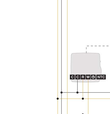
25 StatLink Electrical Schematic Heat Demand 24Vac POWER 24Vac NEUTRAL Setback Signal Setback Signal Optional: connect the setback terminal to the corresponding 1 or 2 terminal that is used by a timer thermostat. Plug for optional expansion module SCHEMATICS Default and Suggested Alternate Color-coded Wiring Schemes Wire FAS105 (red jacket) StatLink default Thermostat Wire (white jacket) LVT Thermostat Wire (brown jacket) C green green green R blue blue white W red red red black white black Heat Link 25


26 StatLink Electrical Schematic Application: Under some circumstances, the StatLink base module may be short cycling the boiler and/or pump. The dry contacts should be connected to either a time delay relay or outdoor reset control to activate a boiler and/or pump Third Party 24 Vac Time Delay Relay (3 min delay suggested) To Condensing Boiler SCHEMATICS 60VA 24 Vac Class II Transformer 26 Heat Link
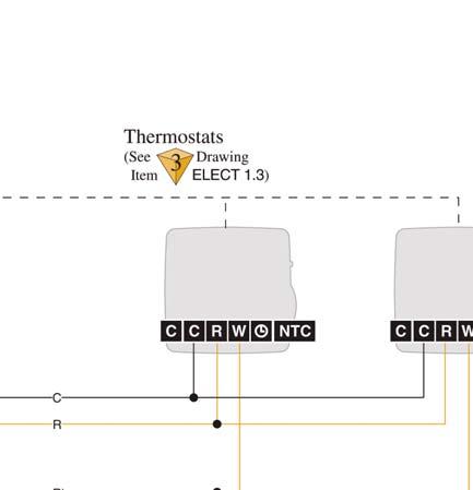
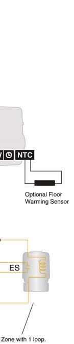
27 StatLink Electrical Schematic Heat Demand 24Vac POWER 24Vac NEUTRAL Setback Signal Setback Signal Optional: connect the setback terminal to the corresponding 1 or 2 terminal that is used by a timer thermostat. Optional Floor Warming Sensor Plug for optional expansion module SCHEMATICS Default and Suggested Alternate Color-coded Wiring Schemes Wire FAS105 (red jacket) StatLink default Thermostat Wire (white jacket) LVT Thermostat Wire (brown jacket) C green green green R blue blue white W red red red black white black Heat Link 27
 or #31000 Series Control Heat Demand Contacts Dry")


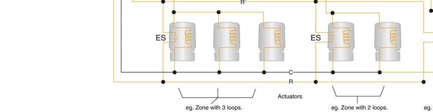
28 StatLink Electrical Schematic Application: Connecting Multiple #40226 Base Modules together. To Boiler Contacts 24 Vac Pump Relay (shown) or #31000 Series Control Heat Demand Contacts Dry contacts are wired in parallel. 60VA 24 Vac Class II Transformer SCHEMATICS Setback signal generator Heat Demand 24Vac POWER 24Vac NEUTRAL Setback Signal Setback Signal Max. 4 actuators/zone. Actuators can be doubled up on the terminals Series Actuators (max. 12) Setback signal tie between modules can be connected to any zone including those with thermostats. 28 Heat Link


 Heat Demand 24Vac POWER 24Vac NEUTRAL")
29 StatLink Electrical Schematic Note: When using polarized transformers the line voltage must be the same phase. 60VA 24 Vac Class II Transformer Series Actuators (max. 12) Heat Demand 24Vac POWER 24Vac NEUTRAL Setback Signal Setback Signal SCHEMATICS Heat Link 29
 and primary pump (P-2).")
30 Electrical Schematic for the #31355 Injection Control SCHEMATICS Application: Injection mixing control activating secondary pump for the low temperature manifold circuit. Boiler c/w system pump (P-1) and primary pump (P-2). 30 Heat Link


31 Electrical Schematic for the #31355 Injection Control Note: If only an indoor or fl oor sensor is used without thermostats or StatLink, then power is required at terminals 1 &2. Note: This is only a concept drawing. The designer must determine whether this application applies to the system. Design must comply with local code requirements. Necessary equipment and other safety and limit devices must be added. SCHEMATICS Heat Link 31


32 Electrical Schematic for the HeatLink Mixing Control SCHEMATICS Application: Connecting Actuators with end switches to the #31355 Indoor-Outdoor Control. 32 Heat Link
33 SCHEMATICS Electrical Schematic for the HeatLink Mixing Control Heat Link 33
 with internal resistor for heat anticipation.")

34 HeatLink Thermostat Wiring SCHEMATICS HeatLink Thermostat Wiring Application: Actuators & thermostats (#46333, #46443, or #46543) with internal resistor for heat anticipation. Note: Due to their inherent temperature overshoot, and long lead/lag times, standard 2 wire thermostats are not recommended for high thermal mass radiant fl oor heating systems. (see pages for further explanation.) 34 Heat Link
 with connection to heat demand contacts or")
")

35 HeatLink Thermostat Wiring HeatLink Thermostat Wiring c/w End Switch Tie-in to Relay Application: Actuators c/w end switch contacts & thermostats (#46333, #46443, or #46543) with connection to heat demand contacts or heating load relay. Note: ➊ End Switch (ES) wires are color coded green. Blue and brown wires are for connections to the transformer, and W (thermostat power output signal) connection to the thermostat. ➋ Due to their inherent temperature overshoot, and long lead/lag times, standard 2 wire thermostats are not recommended for high thermal mass radiant fl oor heating systems. (see pages for further explanation) SCHEMATICS Heat Link 35
 Wiring Application: Actuators c/w")

36 HeatLink Timer Thermostat Wiring SCHEMATICS HeatLink Digital Timer Thermostat (#46643) Wiring Application: Actuators c/w end switch contacts & thermostats connecting to heat demand contacts or heating load relay with setback signal. 36 Heat Link


37 HeatLink Timer Thermostat Wiring HeatLink Digital Heat/Cool Timer Thermostat Wiring Application: Actuators c/w end switch contacts & thermostats connecting to heating, cooling and fan relays with setback signal. SCHEMATICS Heat Link 37

38 HeatLink Thermostat Wiring HeatLink Digital Heat/Cool Thermostat (#46673) Interlock Wiring Application: A single cooling zone can often encompass multiple radiant heating zones. The Digital Heat/Cool Timer Thermostat will turn off heating to its zone when cooling is on. However, all the other heating thermostats in the cooling zone may still call for heat. This means that the heating system and cooling system could be active at the same time and work against each other. Option 1 - Most Comfort: Heating and cooling systems work independently (and possibly simultaneously, except for the zone controlled by the Heat/Cool Timer Thermostat). This option would be used in floor warming applications. Advantages: Straight forward wiring; no interlock SCHEMATICS Disadvantages: Except for the zone controlled by the Heat/Cool Timer Thermostat, the heating and cooling systems may work against each other depending on thermostat settings and zone environment, resulting in extra energy usage. 38 Heat Link

39 HeatLink Thermostat Wiring Option 2 - Interlock: When the Heat/Cool Timer Thermostat calls for cooling, the relay will interrupt the heating system s connection to the boiler. This will prevent the boiler from firing. Advantages: Heating and cooling systems won t be active at the same time. Disadvantages: Zones that may need heat won t receive any. SCHEMATICS Heat Link 39

40 SCHEMATICS HeatLink Thermostat Wiring Option 3 - Interlock with Outdoor Reset Control: If the outdoor temperature is warm enough, the heating system will be in Warm Weather Shut Down (WWSD) mode. When the Heat/Cool Timer Thermostat calls for cooling, the relay will interrupt the heating system s connection to the boiler. If the heating system isn t in Warm Weather Shut Down (WWSD), this will prevent the boiler from firing. The heating system pumps will still run, so any heating zones that may be calling for heat will still receive any residual heat in the system. Advantages: Outdoor temperature feedback Disadvantages: Outdoor Reset Control required 40 Heat Link


41 SCHEMATICS HeatLink Thermostat Wiring Heat Link 41
42 Notes NOTES 42 Heat Link
43


44 Heat Link L3710 HeatLink and StatLink are either registered trademarks or trademarks of HeatLink Group Inc. May 11, 2011 Printed in USA HeatLink Group Inc.
Heat Link. Stat Link Technical Guide. Fourth Version
 Stat Technical Guide Fourth Version Table of ontents About Us...3 Stat System omponents... Thermostatic Zones Defined...6 ol-coded iring Schemes...7 Stat ire to onventional ire Adapter...7 Technical Data
- Data Brochure Universal Reset Module 423
 - Data Brochure Universal Reset Module 423 D 423 08/07 1 Information Brochure Choose controls to match application Application Brochure Design your mechanical applications 2 3 Rough-in Wiring Rough-in
- Data Brochure Universal Reset Module 422
 - Data Brochure Universal Reset Module 422 D 422 08/07 1 Information Brochure Choose controls to match application Application Brochure Design your mechanical applications 2 3 Rough-in Wiring Rough-in
DUAL SENSING DIGITAL THERMOSTAT PRODUCT INSTRUCTIONS. Construction Automotive Industry
 DUAL SENSING DIGITAL THERMOSTAT PRODUCT INSTRUCTIONS www.rehau.com Construction Automotive Industry SCOPE This guide gives instruction regarding REHAU Programmable Digital Thermostat installation and operation.
WWSD. Power. DHW Demand. Maximum. Supply. Minimum Boiler DHW. Zone 1 / Cooling. Pump / Vlv. System Pump. UnOccupied. of full output NRTL/C LR 58223
 Dial the desired duration of the period. Press start button at the time of day you want the UnOcc. period to begin. light turns on. 0 = always = always Pump / Vlv System Pump Zone / Cooling NRTL/C LR 58
- Data Brochure Mixing Control 361
 TIME PRGM 1 2 AMPM UN OVR S M T W T F S - Data Brochure Mixing Control 361 D 361 05/00 The Mixing Control 361 is designed to control the supply water temperature to a hydronic system in order to provide
Boiler Demand Mix 1 Demand Mix 2 Demand DHW Demand Setpoint Demand
 Date Code - Data Brochure Universal Reset Control 374 D 374 10/03 The tekmar Universal Reset Control 374 is designed to maximize the comfort and effi ciency provided by a hydronic heating system. The control
- Data Brochure Mixing Control 360
 - Data Brochure Mixing Control 360 D 360 03/09 The Mixing Control 360 is designed to control the supply water temperature to a hydronic system in order to provide outdoor reset or setpoint operation. The
- Essay Control Functions and Benefits
 - Essay Control Functions and Benefits E 005 07/01 A hydronic heating control system performs many complex and important functions. Each of these functions provide benefits that make the system comfortable,
Better Design, Better Control, Better Systems.
 Product Catalog Better Design, Better Control, Better Systems. At tekmar Control Systems, we believe the indoor comfort of a building depends on the performance of its heating, ventilating & air conditioning
Hydronic & HVAC Control Systems
 tekmar 218 Full Line Catalog Hydronic & HVAC Control Systems HVAC Multi-Staging Alternative Energy Zoning Snow Melting Setpoint tekmarcontrols.com tekmarcontrols.com Better Design, Better Control, Better
INSTRUCTIONS REHAU SILENT DIAL THERMOSTAT #
 INSTRUCTIONS REHAU SILENT DIAL THERMOSTAT #236477-001 Specifications... 1 Overview Silent Dial Thermostat Art. 236477-001... 1 Mounting Location... 3 DIP Switch Configuration... 3 Calibration... 5 Setting
- Data Brochure tekmarnet 4 Thermostat 542e
 - Data Brochure tekmarnet 4 Thermostat 542e D 542e 03/08 1 Information Brochure Choose controls to match application 2 Application Brochure Design your mechanical applications 3 Rough In Wiring Rough-in
T6984 A,D,E Electronic Floating Control Thermostats
 T6984 A,D,E Electronic Floating Control Thermostats FEATURES PRODUCT DATA PI (proportional and integral) control action provides accurate, stable room temperature control. T6984 models are used with Series
4 Wiring Brochure Wiring and
 - Brochure tekmarnet 4 Thermostat 544 D 544 06/05 1 Information Brochure Choose controls to match application Application Brochure Design your mechanical applications 2 3 Rough In Wiring Rough-in 4 Wiring
T7984 A,B,C Electronic Modulating Control Thermostats
 T7984 A,B,C Electronic Modulating Control Thermostats FEATURES PRODUCT DATA APPLICATION These microprocessor-based thermostats provide proportional - integral (PI) individual room temperature control in
ProRadiant Controls, Valves and Actuators
 214 Controls, Valves and Actuators Stock Controls, Valves and Actuators BASIC HEATING CONTROL Features: Modulating mixing valve control Supply temperature high limit Seasonal pump activation Boiler activation
- Brochure D 542. Introduction. Features. tekmarnet 4 Thermostat /05. 5 Data Brochure Control settings wiring instructions
 - Brochure tekmarnet 4 Thermostat 542 D 542 06/05 1 Information Brochure Choose controls to match application Application Brochure Design your mechanical applications 2 3 Rough In Wiring Rough-in 4 Wiring
- Data Brochure D 260. Boiler Control /09
 - Data Brochure Boiler Control 260 D 260 03/09 The Boiler Control 260 is designed to control a single stage heat source in order to provide outdoor reset or Domestic Hot Water () operation. The control
The Universal Reset Control 363 is a microprocessor based control designed to maximize the comfort and efficiency provided by a hydronic
 R Vie Menu % % 1 2 Item F! WWS Vie Menu % % 1 2 Item F! WWS 70 LR 58233 E150539 Universal Reset Control 363 - Data Brochure D 363 12/08 The Universal Reset Control 363 is a microprocessor based control
Heat Link MECHANICAL ROOM IN A BOX. SSP Series SS Manifold Pump Panel Installation, Operation, and Maintenance Manual. L6SSPxx000x SSPLR106T SSPSS106B
 SSP Series SS Manifold Pump Panel Manual GROUND LIVE NEUTRAL CAUTION 5 VOLTS ONLY 0 80 00 00 C F 80 60 40 60 0 0 40 40 60 80 00 SSPLR06T GROUND LIVE NEUTRAL CAUTION 5 VOLTS ONLY 0 80 00 00 C F 80 60 40
DHW / Setpoint Demand WWSD Modulation Boiler Output (x10,000 BTU/hr) External Input Signal Offset / Priority Override
 External Input Signal Offset / Priority Override") Date Code - Data rochure oiler Control 265 D 265 10/03 The tekmar oiler Control 265 can control the supply water temperature on up to three modulating boilers based on outdoor temperature or setpoint requirements.
Date Code - Data rochure oiler Control 265 D 265 10/03 The tekmar oiler Control 265 can control the supply water temperature on up to three modulating boilers based on outdoor temperature or setpoint requirements.
B-40/B-41 Modulating Temperature Controller
 INSTALLATION & OPERATING INSTRUCTIONS B-40/B-41 Modulating Temperature Controller For Raytherm Boilers & Water Heaters H2 514-4001 WH2 2100-4001 Catalog No. 5000.70 Effective: 12-21-11 Replaces: NEW P/N
Rooftop Thermostat Controller Specification and Installation Instructions. Model TRT2422
 ºF / º C Rooftop Thermostat Controller Model TRT2422 Description The TRT2422 is a combination controller and thermostat with a built-in scheduler, which is designed for simple and accurate control of single
TC-9102 Applications
 Application Note January 7, 2004 APPLICATION NOTE TC-9102 Applications Configuring TC-9102 Applications...3 Introduction... 3 Key Concepts... 4 TC-9102 Controller... 4 Control Modes...8 Procedure Overview...
Tools Required Small, flat-head screwdriver Phillips screwdriver (for mounting hardware) Wire stripper and cutter
 Wire stripper and cutter") RADIANT HEATING SYSTEMS HEAT AND COOL THERMOSTAT INSTRUCTION SHEET Technical Data Operating Voltage 24VAC +/- 10% Maximum Load 1.3 Amps at 24VAC 4 x MVA (part number A3020522) 6 x TVA (part number A3010522)
RADIANT HEATING SYSTEMS HEAT AND COOL THERMOSTAT INSTRUCTION SHEET Technical Data Operating Voltage 24VAC +/- 10% Maximum Load 1.3 Amps at 24VAC 4 x MVA (part number A3020522) 6 x TVA (part number A3010522)
Control solutions Biofloor
 TEF234 Electronic room thermostat with display 230V & 24V COMAP proposes a new control system for heating and cooling underfloor. Consisting of a 6 or 10- channels controller (MCF234), analogic (TAF234)
EKC 347 Liquid Level Controller REFRIGERATION AND AIR CONDITIONING. Manual
 EKC 347 Liquid Level Controller REFRIGERATION AND AIR CONDITIONING Manual Contents Introduction...3 Valve compatibility...3 Features...3 Application examples...3 Ordering...3 Operating the EKC 347...4-5
VAV Thermostat Controller Specification and Installation Instructions. Model TRO24T4XYZ1
 Model TRO24T4XYZ1 Description The TRO24T4XYZ1 is a combination controller and thermostat. The VAV Thermostat Controller is designed for simple and accurate control of any variable air volume box in a number
- Data Brochure Mixing Control 360e
 - Data Brochure Mixing Control 360e D 360e 06/11 The Mixing Control 360e is designed to control the supply water temperature to a hydronic system in order to provide outdoor reset or setpoint operation.
- Data Brochure Steam Control 279
 - Data Brochure Steam Control 279 D 279 12/07 The tekmar Steam Control 279 can operate a single on-off steam boiler or an on-off steam valve using outdoor reset. The control determines the on time of the
Emerson Blue Easy Set 1H/1C
 Emerson Blue Easy Set 1H/1C Model: 1F86EZ-0251 Non-Programmable Thermostat with 3 Temperature Pre-Sets Home, Sleep and Away Installation Instructions and User Guide Message to Homeowner Congratulations
DT92 WIRELESS DIGITAL ROOM THERMOSTAT FEATURES PRODUCT SPECIFICATION SHEET
 DT92 WIRELESS DIGITAL ROOM THERMOSTAT PRODUCT SPECIFICATION SHEET The new DT92 family of wireless digital room thermostats is a range of market leading products designed to provide comfort with economy
- Data Brochure Boiler Control 274
 - Data Brochure Boiler Control 274 274_D 03/17 The Boiler Control 274 operates up to four on/off boilers to provide outdoor reset operation, domestic hot water and setpoint operation with priority. When
Feature Summary. I. System
 I. System A. Supports up to 60 VAV HVAC Units 1. Each HVAC Unit Can Support up to 59 VAV Boxes 2. Constant Volume Units Can Be Integrated With VAV Units 3. System Can Support Over 3000 Controllers B. Fill-in
Installation & Operation Manual
 tekmarnet 2 House Control 402 Installation & Operation Manual D 402 09/10 HVAC Systems Replaces: 01/10 Introduction The House Control 402 is designed to operate as part of a complete hydronic heating system
ProRadiant Basic Heating Control Installation Manual 2013
 ProRadiant Basic Heating Control Installation Manual 2013 The Viega Basic Heating Control is designed to control the supply water temperature to a hydronic system in order to provide outdoor reset operation.
T6984F,G Electronic Floating Control Thermostats
 T6984F,G Electronic Floating Control Thermostats FEATURES PRODUCT DATA P+I control action provides accurate, stable room temperature control. Used with ML644 Series 60 Direct Coupled Damper Actuators.
- Data Brochure Boiler Control 264e
 - Data Brochure Boiler Control 264e D 264e 09/09 The kanmor Boiler Control 264e can control the supply water temperature from up to 4 on / off stages based on outdoor temperature, control for Domestic
1F Non-programmable Electronic Digital Heat Pump Thermostat INSTALLATION AND OPERATION INSTRUCTIONS
 FAILURE TO READ AND FOLLOW ALL INSTRUCTIONS CAREFULLY BEFORE INSTALLING OR OPERATING THIS CONTROL COULD CAUSE PERSONAL INJURY AND/OR PROPERTY DAMAGE. DESCRIPTION Your new White-Rodgers Digital Thermostat
Installation & Operation Manual
 tekmarnet 2 House Control 400 Installation & Operation Manual D 400 09/13 HVAC Systems Replaces: 09/10 Introduction The tn2 House Control 400 is designed to operate all of the mechanical equipment in a
- Data Brochure Universal Reset Control 364
 70 7 8 9 - Data Brochure Universal Reset Control 364 D 364 07/01 The Universal Reset Control 364 is designed to maximize the comfort and efficiency provided by a hydronic heating system. The control automatically
Installation & Operation Manual
 tekmarnet 2 House Control 403 Installation & Operation Manual D 403 07/11 HVAC Systems Replaces: 09/10 Introduction The House Control 403 is designed to operate as part of a complete hydronic heating system
ONX908PIT-V1-S1-F1/B Modulating Digital Thermostat
 ONX908PIT-V1-S1-F1/B Modulating Digital Thermostat Installation and operation instructions The ONX908PIT-V1-S1-F1 modulating digital thermostats are designed to provide Proportional-Integral (PI) modulating
OVEN INDUSTRIES, INC.
 OVEN INDUSTRIES, INC. OPERATING MANUAL Model 5C7-252 TEMPERATURE CONTROLLER With PLC Inputs Introduction Thank you for purchasing our controller. The Model 5C7-252 is an exceptionally versatile unit and
BHSAPPMAN 08/00 USA. Applications Manual. Ecomatic / Logamatic Controls. Save These Instructions!
 BHSAPPMAN 08/00 USA Applications Manual Ecomatic / Logamatic Controls Save These Instructions! TABLE OF CONTENTS 1 2 3 4 5 6 7 8 Introduction 1 Terms 2-4 Description of Wiring Terminals 5-7 Application
ECO1ZN3P, ECO2ZN4P ECO
 WARNING HOT This product may have hot fluid circulating through it. DO NOT TOUCH! SOME UNION NUTS MAY BECOME LOOSE AND CONSEQUENTLY LEAK THROUGH TRANSPORTATION VIBRATION AND HANDLING. DO NOT OVERTIGHTEN
PRODUCTS HYDRONICS Controls System Pressure Modulating Control Circle #225 Circle #224 Preassembled System Type L Copper Circle #226 Circle #227
 PRODUCTS HYDRONICS Controls System Pressure Designed for use in closed hydronic systems, Amtrol s Extrol expansion tank has a watertight reservoir for expanded water, a deep drawn steel tank and a butyl
MODEL EM-10 ELECTRIC BOILER CONTROL OPERATION AND INSTRUCTION MANUAL
 MODEL EM-10 ELECTRIC BOILER CONTROL OPERATION AND INSTRUCTION MANUAL The EM-10 Boiler Temperature Control (BTC) is an efficient boiler operator with a digital LCD display with backlight, a boiler pump
- Data Brochure Boiler Control 268
 - Data Brochure Boiler Control 268 D 268 11/10 The tekmar Boiler Control 268 can control the supply water temperature from up to 9 on / off stages based on outdoor temperature, control for Domestic Hot
Installation & Operation Manual
 tekmarnet 2 House Control 400 Installation & Operation Manual D 400 09/10 HVAC Systems Replaces: 01/10 Introduction The House Control 400 is designed to operate as part of a complete hydronic heating system
- Data Brochure Addendum
 - Data Brochure ddendum Control 268 - ddition of Modes and Setpoint Modes D 268 10/03 The tekmar Control 268 has been modified to include the following features: demand for loads alarm New Setpoint operation
Zoning Solutions. Thermostats & Wiring Centers Designed to Maximize Indoor Comfort. A Watts Water Technologies Company
 Zoning Solutions Thermostats & Wiring Centers Designed to Maximize Indoor Comfort HVAC Systems Multi-Staging Alternative Energy Zoning Snow Melting Setpoint A Watts Water Technologies Company Zoning in
SC-9 Controller INSTALLATION AND OPERATING INSTRUCTIONS. SC-9 Applications CONTENTS
 SC-9 Controller MODULAR BOILER CONTROLLER SERIES INSTALLATION AND OPERATING INSTRUCTIONS SC-9 Applications Space heat systems with outdoor reset Constant temperature setpoint control Any of these in combination
Two-Position Electric Duplex Room Thermostats
 TC-XX Series, TC-XX Series, TF- Series Two-Position Electric Duplex Room Thermostats These thermostats provide on-off control of heating/cooling systems. TC-XX Series, TC-XX Series, TF- Series Features:
Smart Temp. Model
 Smart Temp Model 42-160 SINGLE STAGE PROGRAMMABLE THERMOSTAT 1 Heat / 1 Cool Single Stage Thermostat. 5+2 Programmable, Compatible with Gas Heat & Heat Pump System Installation and Operation Manual SPECIFICATIONS:--------------------------------------------------------------------------------
0 C to 50 C ( 32 F to 122 F ) 0% to 95% R.H. non-condensing. 30 to 95% R.H. Dry contact across terminal BI1, BI2 & UI3 to Scom
 0% to 95% R.H. non-condensing. 30 to 95% R.H. Dry contact across terminal BI1, BI2 & UI3 to Scom") Viconics VT7350 Series PIR Ready Fan-coil Controllers General The VT7350 series are PIR Ready low-voltage microprocessor-based fan-coil controllers. Models are available controlling single speed and multi-speed
Viconics VT7350 Series PIR Ready Fan-coil Controllers General The VT7350 series are PIR Ready low-voltage microprocessor-based fan-coil controllers. Models are available controlling single speed and multi-speed
6 Zone 120/60/1vac 3A 24 VAC class 2 2 x 40 VA 2 x 5 amp fuses 1/6 hp, 120 VAC
 Viega Zone Control Applications The Viega Zone Control is a wiring and switching center for individual and / or multi- room control. The Zone Control simplifies wiring between Thermostats and Powerheads.
SC-3 Controller INSTALLATION AND OPERATING INSTRUCTIONS FOR GAS-FIRED, OIL FIRED AND DUAL FUEL HOT WATER HEATING PLANTS. SC-3 Applications CONTENTS
 FOR GAS-FIRED, OIL FIRED AND DUAL FUEL HOT WATER HEATING PLANTS SC-3 Controller MODULAR BOILER CONTROLLER SERIES INSTALLATION AND OPERATING INSTRUCTIONS SC-3 Applications Space Heat Systems With Outdoor
Heat Link MECHANICAL ROOM IN A BOX. SSP Series. SS Manifold Pump Panel Installation, Operation, and Maintenance Manual. L6SSPxx000x-BMS SSPLR106T
 Heat Link SSP Series SS Manifold Pump Panel Manual NEUTRAL GROUND LIVE CAUTION 115 VOLTS ONLY SSPLR106T GROUND LIVE NEUTRAL CAUTION 115 VOLTS ONLY 120 40 60 60 80 100 C F 200 0 180 20 40 140 160 80 100
Heating and D.h.w. Controller RVL482 Basic Documentation
 Heating and D.h.w. Controller RVL482 Basic Documentation Edition: 1.0 Controller series: A CE1P2542en 20.05.2008 Building Technologies Siemens Switzerland Ltd Building Technologies Group International
Table of Contents 1. OVERVIEW SYSTEM LAYOUT SPECIFICATIONS FUNCTION... 11
 Table of Contents 1. OVERVIEW... 3 2. SYSTEM LAYOUT... 4 3. SPECIFICATIONS... 8 3.1 SYSTEM COMPONENTS...9 3.2 PLC INPUTS AND OUTPUTS...9 3.3 FUNCTION KEYS...10 3.4 DEFAULT SET POINTS AND TIMERS...10 4.
OPERATING INSTRUCTIONS
 COMFORT CONTROL CENTER 2 THERMOSTAT OPERATING INSTRUCTIONS PROGRAMMABLE THERMOSTAT MODEL 3314080.000 BLACK 3314080.015 WHITE USA SERVICE OFFICE Dometic Corporation 1120 North Main Street Elkhart, IN 46514
- Data Brochure Boiler Control 264
 - Data Brochure Boiler Control 264 D 264 11/03 The tekmar Boiler Control 264 can control the supply water temperature from up to 4 on / off stages based on outdoor temperature, control for Domestic Hot
MODEL SF-10 CONTROL OPERATION AND INSTRUCTION MANUAL
 MODEL SF-10 CONTROL OPERATION AND INSTRUCTION MANUAL The SF-10 Temperature Control () is an efficient boiler operator with a digital LCD display with backlight, a boiler pump output, and an alarm. The
Hydronic Mechanical Panels
 Hydronic Assemblies Inc. 56 Horse Hill Rd Concord NH 2015-2016 Hydronic Mechanical Panels Contact 4805 Main St. Waitsfield, Vermont 05673 Phone : 802-583-5500 WWW.Houseneeds.com Hydronic Assemblies Inc.
Fan Coil Thermostat. Specification & Installation Instructions TFC54F3Y1. Technical Data
 Fan Coil Thermostat Features: Selectable pipe or 4 pipe system Selectable control mode Selectable fan speed contact Selectable Fahrenheit or Celsius scale Manual Night Set Back override (programmable)
C62. ECL Comfort. User's Guide. Installer's Guide. ECL Comfort C62. User's Guide. Installer's Guide *VIKME102* *087R8091* *087R8091* *VIKME102*
 User's Guide VI.KM.E1.02 2005.09 C62 *VIKME102* *087R8091* www.danfoss.com ECL Comfort User's Guide ECL Comfort Installer's Guide www.danfoss.com *087R8091* *VIKME102* Double mixing controller C62 VI.KM.E1.02
Installation & Operation Manual
 557_D tekmarnet Thermostat 557 09/14 Zoning Replaces: 09/13 Installation & Operation Manual Introduction The tekmarnet Thermostat 557 is a communicating touchscreen thermostat designed to operate either:
C37. ECL Comfort. User's Guide. Installer's Guide. ECL Comfort C37. User's Guide. Installer's Guide *VI7CE602* *087R8070* *087R8070* *VI7CE602*
 User's Guide VI.7C.E6.02 2005.09 C37 *VI7CE602* *087R8070* www.danfoss.com ECL Comfort User's Guide ECL Comfort Installer's Guide www.danfoss.com *087R8070* *VI7CE602* Mixing controller with ON / OFF controlled
Instruction manual. WMCR-2, WMCR-3, WMCR-4 and WMCR-6 Circulator Zone Controllers WMCR-1E and WMCR-4E Expansion Modules
 Instruction manual WMCR-2, WMCR-3, WMCR-4 and WMCR-6 Circulator Zone Controllers WMCR-1E and WMCR-4E Expansion Modules This manual must only be used by a qualified heating installer/service technician.
T60xDFH-4 and T60xDFH-4+PIR Series Thermostat Controllers with Dehumidification and Occupancy Sensing Capability
 T60xDFH-4 and T60xDFH-4+PIR Series Thermostat Controllers with Dehumidification and Occupancy Sensing Capability Product Bulletin T601DFH-4, T602DFH-4, T603DFH-4, T604DFH-4, T605DFH-4, T601DFH-4+PIR, T602DFH-4+PIR,
Instruction Sheet. Press & Hold: Item, to view settings, to test. 24 V ±10% 50/60 Hz 3 VA 120 V (ac) 5 A 1/6 hp pilot 240 VA 20 to 260 V (ac) 2 VA
 5 A 1/6 hp pilot 240 VA 20 to 260 V (ac) 2 VA") Instruction Sheet PC2 1 Two Stage Reset & Control SUPERSEDES : 102-106, dated June 1, 2000 EFFECTIVE: March 1, 2004 Plant ID# 9300-1059 Item 102-106 The PC2-1 is a microprocessor-based control designed
Instruction Sheet PC2 1 Two Stage Reset & Control SUPERSEDES : 102-106, dated June 1, 2000 EFFECTIVE: March 1, 2004 Plant ID# 9300-1059 Item 102-106 The PC2-1 is a microprocessor-based control designed
- Data Brochure Addendum
 - Data Brochure ddendum Control 264 - ddition of Modes and Setpoint Modes D 264 10/03 The tekmar Control 264 has been modified to include the following features: demand for loads alarm New Setpoint operation
Installation & Operation Manual
 Boiler Control 275 Installation & Operation Manual Multi-Staging D 275 01/12 Replaces:03/09 The Boiler Control 275 is designed to stage up to four condensing or non-condensing, modulating or on-off boilers
Logamatic 2107 Controls
 Logamatic 2107 Controls Modular control system for Buderus floor standing boilers with indoor reset, outdoor reset, mixed zones, and solar DHW capability Logamatic 2107 Controls 2 Applications manual Logamatic
C66. ECL Comfort. User's Guide. Installer's Guide. ECL Comfort C66. User's Guide. Installer's Guide. *vi7cc502* *087R8069* *087R8069* *vi7cc502*
 User's Guide VI.7C.C5.02 2005.09 C66 *vi7cc502* *087R8069* www.danfoss.com ECL Comfort User's Guide ECL Comfort Installer's Guide www.danfoss.com *087R8069* *vi7cc502* Mixing controller with PI controlled
Weather compensated flow temperature control of heating and boiler systems
 Instructions ECL Comfort 110 Application 130 Weather compensated flow temperature control of heating and boiler systems User guide, Installation & Maintenance DH-SMT/DK VI.KT.G3.02 Danfoss 06/2008 How
Safety & Installation Instructions
 Model 8800 Universal Communicating Thermostat Safety & Installation Instructions READ AND SAVE THESE INSTRUCTIONS Table of contents Installation Installation location recommendations... 2 Thermostat mounting...
SEQUENCE OF OPERATIONS
 SEQUENCE OF OPERATIONS DDC CONTROLLER: Controller with integral LCD readout for changing set points and monitoring unit operation. Provided with required sensors and programming. Factory programmed, mounted,
AQ252 Universal Injection/Mixing Boiler Reset Control Panels
 AQ252 Universal Injection/Mixing Boiler Reset Control Panels FEATURES PRODUCT DATA PRODUCT DESCRIPTION The AQ252 family of AQUATROL Universal Injection/Mixing Boiler Reset Controls provides simplified,
DT90 DIGITAL ROOM THERMOSTAT FEATURES PRODUCT SPECIFICATION SHEET
 DT90 DIGITAL ROOM THERMOSTAT PRODUCT SPECIFICATION SHEET The new DT90 family of digital room thermostats is a range of market leading products designed to provide comfort with economy in modern heating
TIREE FAN COIL CONTROLLER - T6580
 TIREE FAN COIL CONTROLLER - T6580 PRODUCT SPECIFICATION SHEET 20 DESCRIPTION A pleasing and modern appearance makes the TIREE ideal for living quarter applications, in particular offices and hotels. In
Fan Coil Thermostat Controller Specification and Installation Instructions. Model TFH24F3XYZ2 Stand-alone with Internal Humidity Sensor
 Model TFH24FXYZ2 Stand-alone with Internal Humidity Sensor Description The TFH24FXYZ2 is a fully configurable controller designed specifically for 2 pipe and 4 pipe fan coil applications. No additional
INSTALLATION INSTRUCTIONS MASTER CONTROLLERS MC91AE MC92AE MC93AE MC94AE MC94AEH MC96AEH
 INSTALLATION INSTRUCTIONS MASTER CONTROLLERS MODELS: MC91AE MC92AE MC93AE MC94AE MC94AEH MC96AEH Bard Manufacturing Company Bryan, Ohio 43506 Since 1914...Moving ahead, just as planned. Manual: 2100-189I
Dual Mixing Application
 HBX MIXING APPICATION The CPU-000 configured as a Mixing Control allows for mixing of hitemp boiler (supply) water with lower temp system water, bringing several benefits to a hydronic design and installation.
Product Manual SZ1009
 Product Manual SZ1009 Conventional Heating & Cooling Thermostats with Heat Pump Mode Communicating Thermostats Description The SZ1009 is a microprocessor-based mable thermostats designed for conventional
SAS803WHL-7 Thermostat for floor heating
 SAS803WHL-7 Thermostat for floor heating SAS803WHL-7 is a 7-day programmable thermostat designed for floor warming application or helping to limit floor temperature. This thermostat can conform to water
ELECTRONIC HUMIDISTAT: H270
 ELECTRONIC HUMIDISTAT: H0 ONE OR TWO STAGES HUMIDITY SUPPLY OUTDOOR TEMPERATURE RESET DESCRIPTION The H0 series low voltage, microcomputerbased PI (proportional and integral) humidistats are designed for
Product Manual SZ1022/SZ1031/SZ1035/
 Product Manual SZ1022/SZ1031/SZ1035/ Conventional Heating & Cooling Thermostats Communicating Thermostats Description The SZ1022, SZ1031, and SZ1035, are microprocessorbased mable thermostats designed
IF79 CAUTION CONTENTS YOUR THERMOSTAT REPLACES 1 PREPARATIONS. Installation Instructions for. Heating & Air Conditioning
 CONTENTS Installation Instructions for Heating & Air Conditioning IF79 n- Programmable Heat Pump Thermostat Preparations... 1 Thermostat Details... 1 Removing Old Thermostat... 1-2 Mounting and Wiring...
OEM Alpha Thermostat direct Analog
 OEM Alpha Thermostat direct Analog The OEM Alpha Thermostat direct Analog is a high-quality room thermostat in modern design for the registration and regulation of the desired room temperature, offering
Digital Precise Air Control - DPAC
 Digital Precise Air Control - DPAC Mode Enable Sensor Options The temperature of this sensor will determine if the unit is in heating, cooling or vent mode during Occupied operation. The following options
SAMPLE. added benefit of reduced operating costs during low demand periods, such as spring and fall.
 Chapter 4 Variable-speed pumps. A variable-speed pump varies the flow rate by maintaining a constant pressure differential as zone valves open and close. A sensor measures the difference in pressure between
BB3000 Series. Application. Features. Injection Pump Control General Instructions
 BB3000 Series Injection Pump Control General Instructions Application The TAC Erie BB3000 Injection Pump Control with outdoor reset provides accurate control of the water temperature in the secondary (radiant)
OJ Waterline control system
 OJ Waterline control system THERMOSTATS FOR COMFORT HEATING AND SNOW MELTING Product presentation Mk3 It s all about Room Temperature Control! The essential main goals are: Comfort Flexibility Reliability
2 THERMOSTAT DETAILS 3 REMOVING OLD THERMOSTAT
 CONTENTS Installation Instructions for Heating & Air Conditioning 1F79 n-programmable Heat Pump Thermostat Preparations... 1 Thermostat Details... 1 Removing Old Thermostat... 1-2 Mounting and Wiring...
1.0 Digital Controller
 Form CP-AHU D19_D21_D22 (11-17) D303072-A Obsoletes Forms CP-Preeva-D21 (1-16) Doc No 303072, CP-Preeva-D19 (1-16) Doc No 303071 Applies to: Preeva, MAPS, MAPS II, RPB, RPBL & SSCBL Series For Air Handler
T-32-TS Touchscreen Thermostat. Installation Manual
 T-32-TS Touchscreen Thermostat Installation Manual TABLE OF CONTENTS Introduction...4 Getting Started...5 Installing the Thermostat...6, 8 Disassembly...6 Thermostat Location...6 Mounting the Subbase...6,
2 THERMOSTAT DETAILS 3 REMOVING OLD THERMOSTAT
 CONTENTS Installation Instructions for Heating & Air Conditioning 1F72 5/2 Day Programmable Heat Pump Thermostat Preparations... 1 Thermostat Details... 1 Removing Old Thermostat... 1-2 Mounting and Wiring...