Instruction Manual. B Issue B. next Pump Accessories
|
|
|
- Augustus Lamb
- 5 years ago
- Views:
Transcription


1 Instruction Manual B Issue B next Pump Accessories
2 This page has been intentionally left blank.
3 Contents Section Page 1 Introduction... 1 Contents gea/0086/06/ Scope and definitions Installation and operation safety BX bakeout band Description Technical data Installation Unpack and inspect Fit the BX bakeout band to the pump Electrical connection to a TIC relay box Electrical connection to an independent electrical supply Operation ACX next Air Coolers Description Technical data Installation Unpack and inspect Side (or Radial) mounting Axial mounting Combined radial and axial mounting Electrical connection Power supply requirements Operation TAV vent-valve Description Technical data Installation Unpack and inspect Fit the TAV vent-valve to the pump Electrical connection Operation Inlet-screens Description Technical data Installation Unpack and inspect Fit or remove the inlet-screen PRX10 purge-restrictor Description Technical data Installation Unpack and inspect Fit the purge-restrictor Operation General Calibration of the PRX10 purge-restrictor for different purge gases...26 Edwards Limited All rights reserved. Page i
4 Contents 7 Vent-port adaptor Description Technical data Installation Unpack and inspect Connect the vent-port adaptor VRX vent-restrictor Description Technical data Installation Unpack and inspect VRX vent-restrictor selection Fit the vent-restrictor WCX water-cooler Description Technical data Installation Unpack and inspect Fit the water-cooler to the pump Operation next Interface Cable Description Technical data Installation Unpack and inspect Fit the interface cable to the pump Operation Maintenance For return of equipment, complete the HS Forms at the end of this manual. Illustrations Figure Page 1 Accessories for next pumps - general view (next 240D pump shown) Accessories for next pumps -general view continued (next240d DN100CF shown) ACX next air cooler installation, alternative mounting positions ACX next radial and axial air cooler installation next connector plug and socket TAV vent-valve dimensions (mm) Fitting the TAV vent-valve TAV vent-valve connections Integral mesh centring ring inlet-screen Mesh inlet-screen PRX10 purge-restrictor Vent-port adaptor Extended vent-port adaptor VRX vent-restrictor WCX water-cooling next interface cable...36 Page ii Edwards Limited All rights reserved.
5 Tables Table Page 1 BX bakeout band technical data ACX next Air Cooler technical data ACX next air cooler power requirements TAV vent-valve technical data Inlet-screens technical data PRX10 purge-restrictor technical data Nitrogen flow rate through the PRX10 purge-restrictor Vent-port adaptor technical data Extended vent-port adaptor technical data Vent-restrictor technical data WCX water-cooler technical data next interface cable technical data...35 Contents Associated publications Publication title Vacuum pump and vacuum system safety Publication number P Edwards Limited All rights reserved. Page iii
6 This page has been intentionally left blank. Page iv Edwards Limited All rights reserved.
7 1 Introduction 1.1 Scope and definitions This manual provides installation, operation and maintenance instructions for the Edwards range of accessories for the next pump range. The accessories are shown in Figure 1 and 2. The Item Numbers for the accessories are listed in the appropriate sections. You must use the accessories as specified in this manual. Read this manual before you install accessories onto your next pump. Introduction Important safety information is highlighted as WARNING and CAUTION instructions; you must obey these instructions. The use of WARNINGS and CAUTIONS is defined below. WARNING Warnings are given where failure to observe the instruction could result in injury or death to people. CAUTION Cautions are given where failure to observe the instruction could result in damage to the equipment, associated equipment and process. Throughout this manual, page, figure and table numbers are sequential. The units used throughout this manual conform to the SI international system of units of measurement. When flow rates are specified, the abbreviation 'sccm' is used to mean 'standard cm 3 min -1 : this is a flow of 1 cm 3 min -1 at an ambient temperature of 0 C and a pressure of 1013 mbar (1.013 x 10 5 Pa). In accordance with the recommendations of EN61010, the following warning labels may appear on the pump or its accessories: Warning - refer to accompanying documentation. Warning - risk of electric shock. Warning - hot surfaces. Edwards Limited All rights reserved. Page 1
8 Introduction 1.2 Installation and operation safety WARNING You must use the procedures described in this manual to install your accessory, and you must obey all safety instructions and take note of all appropriate precautions. If you do not, you can damage the accessory or other equipment and can cause injury to people. WARNING The user of the next pump system is responsible for the safe operation and monitoring of the system. WARNING Before you install the accessory, ensure that you switch off the pump and isolate the controller/podule as described below. Before you install your accessory, you must: Switch off the next pump and wait until the pump has stopped rotating. Isolate the pump controller from the electrical supply. Page 2 Edwards Limited All rights reserved.
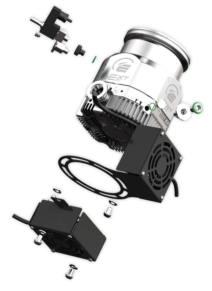
9 Figure 1 - Accessories for next pumps - general view (next 240D pump shown) Introduction 1. DN10NW Adaptor 2. VRX vent-restrictor 3. Manual vent-valve (fitted) 4. TAV Solenoid vent-valve 5. Purge plug (fitted) 6. PRX purge-restrictor 7. DN10NW Adaptor 8. ACX next air cooler (Radial) 9. ACX next ait cooler (Axial) Edwards Limited All rights reserved. Page 3
10 Introduction Figure 2 - Accessories for next pumps -general view continued (next240d DN100CF shown) 1. BX 250 Bake out band (DN100CF envelope shown) 2. BX 250 Bake out band position 3. WCX Water cooling accessory Page 4 Edwards Limited All rights reserved.
11 2 BX bakeout band 2.1 Description You can fit an Edwards BX bakeout band to a next pump to increase the rate of degassing of the pump body, to achieve faster pump down and lower ultimate pressure. You should only fit a BX bakeout band to CF flanged pumps intended for use at ultra high vacuum. BX bakeout bands are available for use with electrical supplies of 110 or 240V a.c., from a rear panel socket on a TIC relay box, or from any suitable electrical supply. 2.2 Technical data BX bakeout band Table 1 - BX bakeout band technical data Electrical supply 110 to 120 V a.c., 50/60 Hz or 200 to 240 V a.c., 50/60 Hz Cable length 3 m Termination 3-pin IEC reverse configuration plug Typical operating 80 C (measured on the pump envelope above the bakeout band) temperature Pollution degree EN61010 Part 1, Category 2 Equipment type Fixed equipment for indoor use only BX250 BX300 BX450 Approximate mass (kg) Minimum diameter (mm) Width of band (mm) Input power (W) Fuse rating 110 to 120 V 1.0 A 1.0 A 1.0 A 200 to 240 V 0.5 A 0.5 A 0.5 A Item Numbers Model To fit pump Item Number BX V next240 B BX V next300 B BX V next400 B BX V next240 B BX V next300 B BX V next400 B Edwards Limited All rights reserved. Page 5
12 BX bakeout band 2.3 Installation Unpack and inspect Remove all packing materials and protective covers and check the BX bakeout band. If the BX bakeout band is damaged, notify your supplier and the carrier in writing within three days; state the Item Number of the BX bakeout band together with your order number and your supplier's invoice number. Retain all packing materials for inspection. Do not use the BX bakeout band if it is damaged Fit the BX bakeout band to the pump WARNING Refer to Figure 2. Before you install the accessory, ensure that the pump is switched off and isolated as described below. 1. Switch off the pump, isolate the pump controller from the electrical supply, and wait until the pump has stopped rotating. 2. Fit the BX bakeout band over the pump body below the inlet flange at the position shown by Figure Tighten the clamping screw Electrical connection to a TIC relay box Refer to the TIC relay box instruction manual for information on how to fit the correct fuse, and how to connect the bakeout band to the TIC relay box Electrical connection to an independent electrical supply If necessary, you can connect the BX bakeout band directly to an appropriate electrical supply. Always ensure that the electrical supply to the bakeout band is interlocked so that it is automatically switched off whenever the next pump operates below normal speed. Check that the rating of the fuse fitted within your electrical supply corresponds to the fuse rating on the BX bakeout band. Page 6 Edwards Limited All rights reserved.
13 2.4 Operation WARNING Do not operate the BX bakeout band when it is not installed on a pump. Without the cooling effect of the pump-body, the temperature of the band can rise to 300 C with the danger of insulation breakdown and fire. WARNING Do not touch the BX bakeout band when it is switched on, as it can get very hot during operation. BX bakeout band CAUTION When using the bakeout heater accessory, water cooling should always be used. If using the heater accessory in combination with baking heaters on the vacuum system, the pump inlet flange temperature should not exceed 80 C. Generally this is ensured by allowing the mating flange on the system to reach a maximum of 120 C. When you use the bakeout band, ensure that there is adequate cooling for the pump and adequate ventilation for the bakeout band. If you have connected the bakeout band to a TIC relay box, refer to the TIC instruction manual for instructions on how to use the TIC to control the operation of the bakeout band. Edwards Limited All rights reserved. Page 7
14 This page has been intentionally left blank. Page 8 Edwards Limited All rights reserved.
15 3 ACX next Air Coolers 3.1 Description The ACX next air cooler is an enclosed 24 V d.c. motor electric fan and a fixing bracket assembly which can be easily fitted to the next range of pumps via bolt holes in the base of the pump. The ACX next air coolers are available for both radial and axial mounting. It is possible to use both variants simultaneously if so desired and space allows. TICs can provide power for one fan only. 3.2 Technical data Table 2 - ACX next Air Cooler technical data Electrical supply 20 to 28 V d.c. Cable cores Red ( V) Black (0 Volts return) Yellow and Green (screen) Pollution degree EN61010 Part 1 Category 2 Power consumption 2.7 Watts Noise emissions 39 dba (per fan) ACX next Air Coolers 3.3 Installation Unpack and inspect Remove all packing and materials and protective covers and check the ACX air cooler. If the ACX air cooler is damaged, notify your supplier and the carrier in writing within three days; state the Item Number of the ACX air cooler together with your order number and your supplier's invoice number. Retain all packing materials for inspection. Do not use the ACX air cooler if it is damaged Side (or Radial) mounting WARNING Before you install the accessory, ensure that you switch off and isolate the pump. Refer to Figure 3 and Switch off pump; wait until the pump has stopped rotating. Isolate the pump drive from the electrical supply. 2. Remove the rubber mounting feet from the base of the pump. 3. Using 4 off M8 x 12 mm button head screws supplied. Fit the ACX radial air cooler mounting bracket to the base of the pump as shown on Figure 4. Ensure the fixing screws are secure. To ensure the radial air cooler works most effectively it is recommended that the fan should be placed directly opposite the pump drive, as shown in Figure 4. This ensures adequate cooling of the next drive. Alternative mounting positions are available as shown in Figure 3. Edwards Limited All rights reserved. Page 9
16 ACX next Air Coolers Figure 3 - ACX next air cooler installation, alternative mounting positions 1. ACX next Air cooler (recommended) 2. Pump outlet port 3. Alternative mounting position Page 10 Edwards Limited All rights reserved.
17 3.3.3 Axial mounting Refer to Figure 4. WARNING Before you install the accessory, ensure that you switch off and isolate the pump. WARNING The axial air cooler does not have an internal guard and MUST NOT operate unless attached to the pump. 1. Switch off pump; wait until the pump has stopped rotating. Isolate the pump drive from the electrical supply. 2. Remove the rubber mounting feet from the base of the pump. ACX next Air Coolers 3. Using the M8 x 12 mm button head screws supplied, fit the ACX axial air cooler to the base of the pump as shown in Figure 1. Ensure the fixing screws are secure Combined radial and axial mounting Refer to Figure 4. Maximum pump cooling can be obtained with the simultaneous use of radial and axial cooling fans. The fan arrangements can be fitted as shown in Figure Switch off pump; wait until the pump has stopped rotating. Isolate the pump drive from the electrical supply. 2. Remove the rubber mounting feet from the base of the pump. 3. Using the M8 x 12 mm button head screws supplied, fit the radial and axial air coolers to the base of the pump as shown in Figure 1. Edwards Limited All rights reserved. Page 11
18 ACX next Air Coolers Figure 4 - ACX next radial and axial air cooler installation 1. Axial air-cooler 2. Radial air-cooler Page 12 Edwards Limited All rights reserved.
19 3.4 Electrical connection CAUTION Ensure that the electrical supply is correct. If it is not, you can damage the ACX air cooler. CAUTION Ensure that the power supply to the cooling accessory can be isolated in a fault condition if required. The ACX air cooler requires a 24 V d.c. electrical supply. You can connect the ACX air cooler to a TIC (Turbo Instrument Controller), a suitable electrical supply or via the next drive electronics. With the air cooler powered via the next drive electronics, the turbo pump will operate satisfactorily with any of the supply voltages specified in the pump product manual. Note: Note:For combined use of both the axial and radial ACX air coolers, a TIC can be used to supply power to one air cooler only. A separate 24 V power supply is required to power the second air cooler. ACX next Air Coolers It is recommended that you fit a separate earth (ground) conductor to the earth of the air cooler; use an un-insulated braid or a separate insulated green/yellow connector and use the M5 x 10 screw and shake-proof washer supplied (attached to the fan cowling) to secure the earth conductor to the air-cooler Power supply requirements Table 3 - ACX next air cooler power requirements Part number Description Operation B ACX next RADIAL KIT 24 V WIRED Powered via the next drive electronics. See section 4.2 B ACX next RADIAL KIT 24 V STD Powered via the TIC or any suitable electrical power supply B ACX next AXIAL KIT 24 V WIRED Powered via the next drive electronics. See section 4.2. B ACX next AXIAL KIT 24 V STD Powered via the TIC or any suitable electrical power supply Connector socket The next turbo pump drive has a 3-way connector socket on the side of the pump as circled in Figure 5. When you receive the pump, this connector may be concealed by a black protective cover. If you intend to use the connector, this cover should be removed by levering with a small screwdriver. A mating plug for this connector is supplied with the pump and the following fan assemblies are available which has a mating plug pre-wired: B ACX next RADIAL KIT 24 V WIRED B ACX next AXIAL KIT 24 V WIRED Edwards Limited All rights reserved. Page 13
20 ACX next Air Coolers Figure 5 - next connector plug and socket V d.c. Out 2. Chassis V d.c. Rtn 3.5 Operation WARNING There is no guard on the outlet of the axial air cooler. Therefore, you must not operate the air cooler unless it is installed on the pump. When operating the ACX air cooler, do not obstruct the fan inlet and ensure there is an adequate supply of cooling air. During operation, if the temperature of any surface of the pump is higher than 60 ºC the pump is too hot and you must increase the cooling. Page 14 Edwards Limited All rights reserved.
21 4 TAV vent-valve 4.1 Description To maintain cleanliness of your vacuum system, we recommend that you vent the pump or vacuum system whenever you switch the pump off. The TAV vent-valves are 24 V d.c. electrical-solenoid operated valves which you can use to vent your vacuum system with atmospheric air or dry nitrogen when you switch the next pump off. The TAV vent-valve is normally open when the solenoid is de-energised. In the case of a power failure, the vacuum system and pump will vent and the pump will slowly come to a halt. TAV vent-valve Refer to Figure 8. The TAV vent-valve is supplied with a sintered bronze inlet filter (1), a riffled hose connector (7) and 3 metres of cable. You can connect your dry nitrogen supply to the hose connector. An NW10 adaptor (Figure 8, item 3) is also supplied to convert the 1/8 inch BSP outlet connector (Figure 6, item 2) of the TAV vent-valve for direct connection to your vacuum system. The TAV vent-valve can be powered by the next drive electronics, controlled from a TIC controller, or from any suitable electrical supply. CAUTION Correct venting is essential to prevent suck-back of hydrocarbon vapour present in the backing line - especially when using oil-sealed rotary vane pumps. To prevent suck-back when stopping the next pump, always begin the venting sequence before the next pump has slowed to 50% of normal rotational speed. Always introduce venting gas to the venting port or to the high vacuum inlet. Never vent to the backing line. Edwards Limited All rights reserved. Page 15
22 TAV vent-valve 4.2 Technical data Table 4 - TAV vent-valve technical data TAV5 TAV6 Maxiumum inlet pressure 1 bar gauge, 2 x 10 5 Pa 1 bar gauge, 2 x 10 5 Pa Orifice diameter 0.5 mm 1.0 mm Helium leak rate (valve closed) < 1 x 10⁻⁸ mbar l s -1 < 1 x 10⁻⁶ mbar l s -1 < 1 x 10⁻⁶ Pa l s -1 < 1 x 10⁻⁴ Pa l s -1 Valve inlet-filter Sintered bronze Sintered bronze Hose connector Riffled nozzle for 4 mm bore tube Riffled nozzle for 4 mm bore tube Dimensions See Figure 6 See Figure 6 Mass 0.08 kg 0.08 kg Item Numbers B B Configuration Normally open Pollution degree EN61010 Part 1, Category 2 Equipment type Fixed equipment for indoor use only Nominal electrical supply voltage 24 V d.c. Electrical supply voltage range 15 to 24 V d.c. Pull-in voltage 14 V d.c. Drop-out voltage 10 V d.c. Power consumption 1.8 W Cable type and length 2-core screened, unterminated, 3 m long Cable cores Red (positive), black (negative) Valve electrical connector type 2 pole and earth (ground), miniature DIN Vale inlet-connection M5 female Valve outlet-connection 1/8 inch BSP Figure 6 - TAV vent-valve dimensions (mm) 1. M5 female thread 2. 1/8 inch BSP male thread Page 16 Edwards Limited All rights reserved.
23 4.3 Installation Unpack and inspect Remove all packing materials and protective covers and check the TAV vent-valve. If the TAV vent-valve is damaged, notify your supplier and the carrier in writing within three days; state the Item Number of the TAV vent-valve together with your order number and your supplier's invoice number. Retain all packing materials for inspection. Do not use the TAV vent-valve if it is damaged Fit the TAV vent-valve to the pump TAV vent-valve WARNING Before you install the accessory, ensure that you switch off the pump and disconnect the power supply as described below. CAUTION When fitting the TAV vent-valve, apply torque to the steel body only. On no account should torque be applied to the solenoid body, failure to do so could damage the valve which may cause it to leak. Figure 7 - Fitting the TAV vent-valve Edwards Limited All rights reserved. Page 17
24 TAV vent-valve Refer to Figure Switch off the pump, isolate the pump controller from the electrical supply, and wait until the pump has stopped running. 2. If your next pump has a manual vent-valve, unscrew and remove it, then continue at step If your next pump does not have a manual vent-valve, fit the vent-valve adaptor to a suitable NW10 flange on your pump or vacuum system. 4. Check that the TAV vent O-ring (Figure 8, item 4) is fitted and screw the TAV vent-valve into the vent-valve adaptor or into the 1/8 inch BSP hole vacated by the manual vent-valve. 5. Connect your dry nitrogen or other inert gas supply pipeline to the M5 inlet (Figure 8, item 2) or use the riffled hose connector (Figure 8, item 7) supplied. 6. If you vent the pump with air, fir the sintered bronze inlet-filter (Figure 8, item 1) to protect your system against the entry of dust Electrical connection CAUTION Ensure that the electrical supply is correct. If it is not, you can damage the TAV vent-valve. The TAV vent-valve requires a 24 V d.c. electrical supply. The next pump includes drive electronics which provide facilities for regulated pulsed venting (see pump manual for details). This ensures that your vacuum system can be vented to atmosphere as rapidly as possible without damage to the pump. Alternatively, you can connect the TAV vent-valve to a TIC (see TIC instruction manual for details) or your own electrical supply. Page 18 Edwards Limited All rights reserved.
25 4.4 Operation CAUTION If you manually vent the pump when it is at full rotational speed and the rate of pressure rise is too high, the pump life may be reduced. When using the manual vent-valve supplied, we recommend that you either limit the vent or only open the vent-valve after the next pump speed has fallen to 50% of full rotational speed. Do not vent the backing line as this may lead to contamination. If you vent into your vacuum system and use an oil sealed rotary backing pump, select a point upstream of the next pump, to prevent oil back-streaming from the backing line. Operation of the TAV vent-valve depends on how you have conneted it: TAV vent-valve If you have connected the TAV vent-valve to the drive electronics of the next pump; refer to the next pump instruction manual. If you have connected the TAV vent-valve to a TIC: refer to the TIC instruction manual for operating instructions. If you have connected the TAV vent-valve to your own electrical supply, switch on the electrical supply to operate the vent-valve. Figure 8 - TAV vent-valve connections 1. Air filter 2. Inlet-port 3. Vent-valve adaptor 4. O-ring 5. Alternative electrical supply connector position 6. Electrical supply connector 7. Hose connector Edwards Limited All rights reserved. Page 19
26 This page has been intentionally left blank. Page 20 Edwards Limited All rights reserved.
27 5 Inlet-screens 5.1 Description Inlet-screens are supplied with all new next pumps. If you have a next pump without an inlet-screen, we recommend that you fit an inlet-screen for additional safety. The only exception to this is the main port in the END faces of split flow pumps. Plastic covers must be retained on these variants until ready to install to minimise the risk of injury from impeller blades. Inlet-screens The inlet-screen prevents the entry of debris into the pump and also prevents people from coming into contact with the blades if the pump is switched on when it is disconnected from your vacuum system. 5.2 Technical data Note: Refer to the pump instruction manual for details of performance reductions when an inlet-screen is fitted. Table 5 - Inlet-screens technical data Pump inlet flange size Pump model Item number ISO100 coarse inlet-screen next240 / 300 B ISO100 fine inlet-screen next240 / 300 B ISO160 coarse inlet-screen next400 B ISO160 fine inlet-screen next400 B CF100 coarse inlet-screen next240 / 300 B CF100 fine inlet-screen next240 / 300 B CF160 coarse inlet-screen next400 B CF160 fine inlet-screen next400 B Installation Unpack and inspect Remove all packing materials and protective covers and check the inlet-screen. If the inlet-screen is damaged, notify your supplier and the carrier in writing within three days; state the Item Number of the inlet-screen together with your order number and your supplier's invoice number. Retain all packing materials for inspection. Do not use the inlet-screen if it is damaged. Edwards Limited All rights reserved. Page 21

28 Inlet-screens Fit or remove the inlet-screen WARNING Before you install the accessory, ensure that you switch off the pump and disconnect the power supply as described below. WARNING If you remove the inlet-screen, there will be a risk of injury from exposed sharp edges in the pump. CAUTION Do not remove the inlet-screen unless you can be sure that debris cannot fall into the pump. Debris which falls into the pump can seriously damage it. 1. Switch off the pump, isolate the pump controller from the electrical supply, and wait until the pump has stopped rotating. 2. Use the following appropriate procedure according to the type of inlet-screen Integral mesh centring ring inlet-screen Refer to Figure 9. Locate the inlet-screen between the next pump flange and the mating flange on your vacuum system chamber. Figure 9 - Integral mesh centring ring inlet-screen Page 22 Edwards Limited All rights reserved.
29 Mesh inlet-screen Refer to Figure 10. Insert the mesh inlet-screen into the pump inlet as shown in Figure 10. Figure 10 - Mesh inlet-screen Inlet-screens Edwards Limited All rights reserved. Page 23
30 This page has been intentionally left blank. Page 24 Edwards Limited All rights reserved.
31 6 PRX10 purge-restrictor 6.1 Description The PRX10 purge-restrictor (shown in Figure 11) sets the purge gas flow rate. The next pump range has a purge port facility to allow you to purge the motor and bearing cavity with dry nitrogen or other inert gas. Note: You will need a vent port adaptor (see Section 7) to fit the PRX10 purge-restrictor. 6.2 Technical data Nominal nitrogen flow rate * Flange size Item Number * At a supply pressure of 0 bar gauge (1 x 10 5 Pa) Table 6 - PRX10 purge-restrictor technical data 255 sccm, 0.42 mbar l s -1, 42 Pa l s -1 NW10 B PRX10 purge-restrictor 6.3 Installation Unpack and inspect Remove all packing materials and protective covers and check the PRX10 purge-restrictor. If the PRX10 purge-restrictor is damaged, notify your supplier and the carrier in writing within three days; state the Item Number of the PRX10 purge-restrictor together with your order number and your supplier's invoice number. Retain all packing materials for inspection. Do not use the PRX10 purge-restrictor if it is damaged Fit the purge-restrictor WARNING Before you install the accessory, ensure that you switch off the pump and disconnect the power supply as described below. CAUTION Do not exert any sideways force on the purge- restrictor when you clamp it into place. If you do, you can damage the seal between the O-ring (Figure 11, item 2) and the body of the purge-restrictor. If the seal is damaged, gas may leak through the seal and you will not be able to properly control gas flow into the pump. Note: If you will use a purge gas other than nitrogen, you must calibrate the purge-restrictor (refer to Section 6.4.2) before you connect your purge gas supply. 1. Switch off the pump, isolate the pump controller from the electrical supply, and wait for the pump to stop rotating. 2. Remove the blank and clamp from the purge-port on the pump. Edwards Limited All rights reserved. Page 25
32 PRX10 purge-restrictor 3. Attach your purge gas supply pipeline (which must be terminated with an NW10 flange) to the purge-port with the PRX10 purge-restrictor in place of the normal NW10 centring-ring. 4. Carefully secure the connection with the NW10 clamp. 6.4 Operation General The PRX10 purge-restrictor, as supplied, is adjusted to restrict the flow rate of dry nitrogen at a supply pressure of 0 bar gauge (1 x 10 5 Pa) to 25 sccm (0.42 mbar l s -1, 42 Pa l s -1 ). You can increase the supply pressure to increase the flow rate; see Table 7. For most applications, you can use a nitrogen flow rate of 25 sccm (0.42 mbar l s -1, 42 Pa l s -1 ) to 30 sccm (0.5 mbar l s -1, 50 Pa l s -1 ). To do this, your nitrogen supply pressure must be 0.1 to 0.2 bar gauge (1.1 x 10 5 to 1.2 x 10 5 Pa). Do not exceed the maximum purge gas supply pressure given in the instruction manual supplied with your pump Calibration of the PRX10 purge-restrictor for different purge gases The purge gas flow rate at a particular supply pressure will change if you use a different purge gas. If you want to use a different purge gas, use the procedure below to adjust the flow rate. 1. Fit the PRX10 purge-restrictor to the pump as described in Section Fit a calibrated mass flow meter between your purge gas supply and the PRX10 purge-restrictor. 2. Switch on the backing pump to evacuate the next pump and then turn on your purge gas supply. 3. Monitor the indicated purge gas flow rate while you adjust the purge gas supply pressure. If you can achieve the required flow rate, you do not need to adjust the purge-restrictor; in this case, continue at Step 5 below. 4. Refer to Figure 11. If you cannot achieve the required flow rate, undo the locknut (3) on the purge-restrictor and use a small screwdriver to turn the adjustment screw (4) clockwise to decrease the flow rate, or anticlockwise to increase the flow rate. Tighten the locknut. 5. Turn off your purge gas supply, remove the mass flow meter and connect your purge gas supply to the purgerestrictor. Table 7 - Nitrogen flow rate through the PRX10 purge-restrictor Nitrogen supply pressure Nitrogen flow rate bar gauge bar absolute Pa sccm mbar l s -1 Pa l s x x x x x x x Page 26 Edwards Limited All rights reserved.
33 Figure 11 - PRX10 purge-restrictor 1. Filtered purge gas inlet to PRX10 purge-restrictor 2. O-ring 3. Locknut 4. Adjustment screw PRX10 purge-restrictor Edwards Limited All rights reserved. Page 27
34 This page has been intentionally left blank. Page 28 Edwards Limited All rights reserved.
35 7 Vent-port adaptor 7.1 Description The 1/8 inch BSP(P) male to NW10 vent-port adaptor can be used to convert the 1/8 inch BSP(P) female vent-port on all next pumps to an NW10 flange. An alternative vent-valve to the TAV 5/6 or a vent pipeline may then be fitted to this flange. See Figure 12. Figure 12 - Vent-port adaptor Vent-port adaptor 1. NW10 flange 2. O-ring 3. 1/8 inch BSP male thread 4. Removable flow-restrictor The vent-port adaptor is supplied with a removable flow restrictor and an O-ring to seal the adaptor to the pump. It is suited for all next pump types. Also available is an extended vent-port adaptor which is intended for use with the split-flow turbo pumps where the backing port is too close to the vent-port to allow the standard vent-port adaptor to be used. The extended ventport adaptor is supplied with an O-ring to seal to the pump, NW10 centering ring and NW10/16 clamping ring. Refer to Figure 13. Figure 13 - Extended vent-port adaptor 1. NW10 flange 2. O-ring 3. 1/8 inch BSP male thread 4. M5 internal thread CAUTION The extended vent-port adaptor is not supplied with a removable flow restrictor. Venting a turbo pump from atmosphere, through the extended vent-port adaptor, would cause damage to the turbo pump. To vent a turbo pump when using the extended vent-port adaptor, you must either control the flow-rate to the adaptor or incorporate a 0.8 mm orifice in the pipeline used to connect to the extended vent-port adaptor. Edwards Limited All rights reserved. Page 29
36 Vent-port adaptor The extended vent-port adaptor is best suited to the following pump types. next240 next300 next Technical data Internal diameter Flange size Item number Table 8 - Vent-port adaptor technical data 0.8 mm NW10 B Table 9 - Extended vent-port adaptor technical data Internal diameter Flange size Item Number M5 thread NW10 B Installation Unpack and inspect Remove all packing materials and protective covers and check the vent-port adaptor. If the vent-port adaptor is damaged, notify your supplier and the carrier in writing within three days; state the Item Number of the vent-port adaptor together with your order number and your supplier's invoice number. Retain all packing materials for inspection. Do not use the vent-port adaptor if it is damaged Connect the vent-port adaptor WARNING Before you install the accessory, ensure that you switch off the pump and disconnect the power supply as described below. 1. Switch off the pump, isolate the pump controller from the electrical supply, and wait for the pump to stop rotating. 2. Unscrew and remove the manual vent-valve from the next pump. 3. Refer to Figure 12 and 13. Check that the vent-port adaptor has an O-ring (2) fitted and screw the adaptor into the 1/8 inch BSP vent-port. Tighten the adaptor so that it seals firmly against the face of the vent-port. 4. Connect your vent pipeline to the NW10 flange (1) of the adaptor with suitable fittings. Page 30 Edwards Limited All rights reserved.
37 8 VRX vent-restrictor 8.1 Description Note: A VRX vent-restrictor can be fitted in any next vent port or purge port. Fit a VRX vent-restrictor to your next pump if you will vent the pump when the pump speed is above 50% of full rotational speed. The vent-restrictor restricts the flow-rate of the vent gas into the next pump. You can fit the VRX vent-restrictor directly to the inlet of a vent-port adaptor, together with a TAV vent-valve (if required). Note that you must fit the vent-restrictor before you fit the TAV vent-valve or vent-port adaptor. 8.2 Technical data Table 10 - Vent-restrictor technical data VRX vent-restrictor VRX Orifice diameter Item Number VRX mm B VRX mm B VRX mm B VRX mm B VRX mm B Installation Unpack and inspect Remove all packing materials and protective covers and check the vent-restrictor. The VRX identification number (Figure 14, item 5) is located on the restrictor base; for example, if you have a VRX20 vent-restrictor, 20 will be shown on the base of the restrictor. If the vent-restrictor is damaged, notify your supplier and the carrier in writing within three days; state the Item Number of the vent-restrictor together with your order number and your supplier's invoice number. Retain all packing materials for inspection. Do not use the vent-restrictor if it is damaged VRX vent-restrictor selection Make sure that you have the correct vent-restrictor for your pump and vacuum system. Refer to your next pump instruction manual for selection details. You must not exceed the maximum allowable rate of pressure rise specified in the next pump instruction manual Fit the vent-restrictor WARNING Before you install the accessory, ensure that you switch off the pump and disconnect the power supply as described below. Use the following procedure to fit the vent-restrictor to a next pump: Edwards Limited All rights reserved. Page 31
38 VRX vent-restrictor 1. Switch off the pump, isolate the pump controller from the electrical supply, and wait until the pump has stopped rotating. 2. Remove the vent-valve or plug from the next pump, or disconnect the vacuum connections from the purge port as appropriate. 3. Refer to Figure 14. If a vent-restrictor is already fitted, fit a suitable M3 screw into the M3 taped hole (2) in the restrictor, and then pull the screw to remove the old vent-restrictor. 4. Fit a suitable M3 screw to the new restrictor and push the new restrictor fully into the vent-port or purge port of the next port. 5. Remove the M3 screw and refit the vent-valve or plug, or reconnect the vacuum connections to the purge port. Figure 14 - VRX vent-restrictor 1. O-ring 2. M3 tapped hole 3. Sealing washer 4. Orifice diameter 5. VRX identification number Page 32 Edwards Limited All rights reserved.
39 9 WCX water-cooler 9.1 Description A WCX water-cooler can be fitted to all next pumps, to provide water cooling during pump operation. Refer to the pump instruction manual to determine the operating conditions under which you must use water cooling. 9.2 Technical data Item number B Water connection dimensions Table 11 - WCX water-cooler technical data To fit pump models All next pumps Push-fit connectors suitable for 10 mm OD plasic pipe WCX water-cooler 9.3 Installation Unpack and inspect Remove all packing materials and protective covers and check the WCX water-cooler. If the water-cooler is damaged, notify your supplier and the carrier in writing within three days; state the Item Number of the water-cooler together with your order number and your supplier's invoice number. Retain all packing materials for inspection. Do not use the water-cooler if it is damaged Fit the water-cooler to the pump WARNING Before you install the accessory, ensure that you switch off the pump and disconnect the power supply as described below. 1. Switch off the pump. Isolate the pump controller from the electrical supply, and wait until the pump has stopped rotating. 2. Refer to Figure 2 & 15. Fit the water-cooler to the pump as described below WCX water-cooler 1. If necessary, remove the old water -cooler from the pump, and retain the fixing screws. 2. Use the screws removed in step 1, or use the two supplied, to secure the new water-cooler to the pump in position as shown in Figure Push the 10 mm OD plastic tube (not supplied) into the push fit connectors ensuring that they are securely inserted. 4. Briefly turn on the cooling water supply and check for leaks. Seal any leaks found. Edwards Limited All rights reserved. Page 33
40 WCX water-cooler 9.4 Operation CAUTION Ensure that the cooling-water flow is correct for the pump operating conditions. Insufficient or excess coolingwater flow can damage the pump. Refer to your next pump instruction manual for: The operating conditions under which you must use water-cooling. The necessary cooling-water supply flow rates and temperatures. Figure 15 - WCX water-cooling Item number Product description Quantity 1 Water-cooling block 1 2 M6 x 16 socket cap screw 2 3 Push fit connector 10 OD pipe 1/4 BSP 2 4 Plastic tube 10 OD ref only Page 34 Edwards Limited All rights reserved.
41 10 next Interface Cable 10.1 Description The next interface cable allows you to connect the serial link of an next Pump to a PC. Serial commands can then be used to control and monitor the next Pump. Refer to the pump instruction manual for information on the serial protocol utilisation, including a full serial command set and details of the required message structure Technical data Item number B Pump connection Supply connection PC connection Table 12 - next interface cable technical data To fit pump models All next pumps 15 way female D-type socket (dual-entry back shell) 15 way male D-type plug (single-entry back shell) 9 way female D-type socket (single-entry back shell) next Interface Cable 10.3 Installation Unpack and inspect Remove all packing materials and check the interface cable. If the interface cable is damaged, notify your supplier and the carrier in writing within three days; state the Item Number of the interface cable together with your order number and your supplier's invoice number. Retain all packing materials for inspection. Do not use the interface cable if it is damaged Fit the interface cable to the pump WARNING Before you install the accessory, ensure that you switch off the pump and disconnect the power supply as described below. 1. Switch off the pump. Isolate the pump controller from the electrical supply and wait until the pump has stopped rotating. 2. Disconnect the next pump logic interface cable from the TIC Turbo Instrument Controller or TIC Turbo Controller or from your own systems, depending upon your connection method. 3. Refer to Figure 16 for the interface cable connection diagram. 4. Connect the 15 way female D-type socket (pump connection) of the interface cable to the next pump logic interface cable. 5. Connect the 15 way male D-type plug (supply connection) of the interface cable either to the back of the TIC (refer to the TIC instruction manual for further information) or to the pump connection of your own system, depending upon your connection method. 6. Connect the 9 way female D-type socket (PC connection) of the interface cable either to the serial port of your PC or to a suitable USB to RS232 converter, depending upon your PC serial port availability. Edwards Limited All rights reserved. Page 35
42 next Interface Cable 10.4 Operation WARNING Ensure that the interface cable is correctly and securely fitted before turning on the power supply and starting the pump, as described in Section Refer to your next pump instruction manual for information detailing pump operation and serial protocol utilisation. Figure 16 - next interface cable 1. Pump connection 2. Supply connection 3. PC connection Page 36 Edwards Limited All rights reserved.
43 11 Maintenance Edwards next accessories require little user maintenance and contain no user serviceable parts. To maintain the accessories in normal use, do the appropriate checks below when you maintain the pump. Check that all mechanical fixings are secure. Check that any electrical connections are secure. Check that any electrical supply cables are undamaged. Maintenance Edwards Limited All rights reserved. Page 37
44 This page has been intentionally left blank. Page 38 Edwards Limited All rights reserved.
NRA Issue A Original. Instruction Manual EXT555H 98/37/EC 89/336/EEC 73/023/EEC
 NRA-266-880 Issue A Original Instruction Manual EXT555H 98/37/EC 89/336/EEC 73/023/EEC CONTENTS Section Title Page 1 INTRODUCTION 1 i 1.1 Scope and definitions 1 2 TECHNICAL DATA 3 2.1 General 3 2.2 Pumping
Instruction Manual. EXT250M Turbomolecular Pump. B Issue C. Description Flange size Cable length Item Number
 B735-21-880 Issue C Instruction Manual EXT250M Turbomolecular Pump Description Flange size Cable length Item Number EXT250M Turbomolecular Pump, with EXC300M Controller and pump-to-controller cable DN100ISO-K
Instruction Manual. EXT Compound Molecular Pumps: EXT70H, EXT70Hi *, EXT250H and EXT250Hi
 Instruction Manual B740-01-880 Issue J EXT Compound Molecular Pumps: EXT70H, EXT70Hi *, EXT250H and EXT250Hi Description EXT70H/ISO63 EXT70H/63CF EXT70H/NW40 EXT250Hi/ISO100 EXT250H/100CF EXT250H/ISO100
Instruction Manual. IT20K, IT100, IT300 and IT800 Inlet Traps. A Issue F. ITC800 Inlet Chemical Trap. ITD20K Inlet Desiccant Trap
 Instruction Manual A441-01-880 Issue F IT20K, IT100, IT300 and IT800 Inlet Traps Description ITO20K Inlet Catchpot ITC20K Inlet Chemical Trap ITD20K Inlet Desiccant Trap ITF20K Inlet Dust Filter ITO100
Instruction Manual. IT20K, IT100, IT300 and IT800 Inlet Traps. idealvac.com (505) idealvac.com. ITC800 Inlet Chemical Trap
 idealvac.com. ITC800 Inlet Chemical Trap") Instruction Manual A441-01-880 Issue G Original IT20K, IT100, IT300 and IT800 Inlet Traps idealvac.com (505)872-0037 idealvac.com Description ITO20K Inlet Catchpot ITC20K Inlet Chemical Trap ITD20K Inlet
Instruction Manual A441-01-880 Issue G Original IT20K, IT100, IT300 and IT800 Inlet Traps idealvac.com (505)872-0037 idealvac.com Description ITO20K Inlet Catchpot ITC20K Inlet Chemical Trap ITD20K Inlet
Instruction Manual. M150 Gas Reactor Column. A Issue B
 A553-01-880 Issue B Instruction Manual M150 Gas Reactor Column Manor Royal, Crawley, West Sussex, RH10 2LW, UK Telephone: +44 (0) 1293 528844 Fax: +44 (0) 1293 533453 http://www.bocedwards.com Declaration
Instruction Manual. Vapour Pump Thermal Snap-Switches. Cooling-Fail Thermal Snap-Switch
 Instruction Manual B023-04-880 Issue E Original Vapour Pump Thermal Snap-Switches Description Cooling-Fail Thermal Snap-Switch Cooling-Fail Thermal Snap-Switch Cooling-Fail Thermal Snap-Switch Pump-Ready
Hodge Clemco Ltd. MJC Mini Cartridge Filters Owners Manual. TSOM 556 Date of issue 13/07/04. Hodge Clemco Ltd
 1 MJC Mini Cartridge Filters Owners Manual TSOM 556 Date of Issue: 13.07.04 Orgreave Drive, Sheffield South Yorkshire. S13 9NR Tel:0114 254 0600 Fax: 0114 2540250 Email:sales@hodgeclemco.co.uk www.hodgeclemco.co.uk
CARVER CASCADE 2 & CASCADE 2 GE CARAVAN WATER HEATER INSTALLATION INSTRUCTIONS LEAVE THESE INSTRUCTIONS WITH THE USER
 CARVER - CASCADE 2 & CASCADE 2 GE CARAVAN WATER HEATER INSTALLATION INSTRUCTIONS LEAVE THESE INSTRUCTIONS WITH THE USER 1:0 SPECIFICATIONS Water capacity Water connections Water supply 9 litres (2 gallons)
INSTRUCTION MANUAL (ATEX / IECEx)
") INSTRUCTION MANUAL (ATEX / IECEx) BExS110D and BExS110D-R Sounder For use in Flammable Gas and Dust Atmospheres BExS110D BExS110D-R 1) Warnings DO NOT OPEN WHEN AN EXPLOSIVE ATMOSPHERE IS PRESENT DO NOT
INSTRUCTION MANUAL (ATEX / IECEx) BExS110D and BExS110D-R Sounder For use in Flammable Gas and Dust Atmospheres BExS110D BExS110D-R 1) Warnings DO NOT OPEN WHEN AN EXPLOSIVE ATMOSPHERE IS PRESENT DO NOT
LyoDry Compact Benchtop Freeze Dryer INSTALLATION AND OPERATION MANUAL
 UK MANUFACTURERS OF LYODRY FREEZE DRYERS & BESPOKE HIGH VACUUM SYSTEMS VACUUM PUMPS - SPARES - SERVICE Benchtop Freeze Dryer INSTALLATION AND OPERATION MANUAL Issue 6 Date 31/05/17 PLEASE READ THIS DOCUMENT
Operation and Maintenance Manual Chamber Conditioning Unit, CCU 06. Document Number: EC OM 6847 Revision: 3
 Operation and Maintenance Manual Chamber Conditioning Unit, CCU 06 Part Number: KI40053 Document Number: EC OM 6847 Revision: 3 TABLE OF CONTENTS Table Of Contents Approval Sheet List of Abbreviations
TECHNICAL MANUAL CX(E) SPLIT SYSTEMS. Tel: Fax:
 SPLIT SYSTEMS. Tel: Fax:") TECHNICAL MANUAL CX(E) SPLIT SYSTEMS CONTENTS INDEX PART NUMBERS, OPTIONS, UNIT COMBINATIONS, DIMENSIONS & WEIGHTS 3 PERFORMANCE DATA & AIR FLOW 4 SOUND POWER AND SOUND PRESSURE LEVELS 5 ELECTRICAL DATA
TECHNICAL MANUAL CX(E) SPLIT SYSTEMS CONTENTS INDEX PART NUMBERS, OPTIONS, UNIT COMBINATIONS, DIMENSIONS & WEIGHTS 3 PERFORMANCE DATA & AIR FLOW 4 SOUND POWER AND SOUND PRESSURE LEVELS 5 ELECTRICAL DATA
Vacuum Switch, Differential Pressure Adapter, Switching Amplifier
 Operating Manual Incl. EU Declaration of Conformity Vacuum Switch, Differential Pressure Adapter, Switching Amplifier VSC150, SV tina42e1-b (2017-03) 1 Product Identification In all communications with
Linkam Scientific Instruments USER GUIDE TS1500 TS1200 TS1000. High Temperature Stage
 Linkam Scientific Instruments TS1500 TS100 TS1000 High Temperature Stage USER GUIDE Contents Before Setting Up your Equipment... 3 Important Notice... 4 Warranty... 4 Technical Support... 4 Equipment Maintenance...
Technology for Vacuum Systems. Instructions for use
 page 1 of 8 Technology for Vacuum Systems Instructions for use GKF 1000i Cold trap page 2 of 8 Content Safety information!...3 General information...3 Intended use...3 Setting up and installing the cold
MODEL A-316 CARBON MONOXIDE (CO) MONITOR AND ALARM FOR COMPRESSED AIR TESTING
 MONITOR AND ALARM FOR COMPRESSED AIR TESTING") MODEL A-316 CARBON MONOXIDE (CO) MONITOR AND ALARM FOR COMPRESSED AIR TESTING FOR OPERATION FROM 115 AC POWER Andersen Medical Gas 12 Place Lafitte Madisonville, LA 70447 http://www.themedicalgas.com 1-866-288-3783
MODEL A-316 CARBON MONOXIDE (CO) MONITOR AND ALARM FOR COMPRESSED AIR TESTING FOR OPERATION FROM 115 AC POWER Andersen Medical Gas 12 Place Lafitte Madisonville, LA 70447 http://www.themedicalgas.com 1-866-288-3783
Vacmobile 20/2. Instruction manual OPERATION & SERVICE
 This instruction manual provides general instructions for the Vacmobile 20/2 vacuum system. This machine may use either the Becker U4.20 or the PVR EM 20/B vacuum pump. Service information specific to
B. Unit construction shall comply with ASHRAE 15 Safety Code, NEC, and ASME applicable codes (U.S.A. codes).
.") Guide Specifications PART 1 GENERAL 1.01 SYSTEM DESCRIPTION Microprocessor controlled, air-cooled liquid chiller utilizing scroll compressors, low sound fans, hydronic pump system and optional fluid storage
Guide Specifications PART 1 GENERAL 1.01 SYSTEM DESCRIPTION Microprocessor controlled, air-cooled liquid chiller utilizing scroll compressors, low sound fans, hydronic pump system and optional fluid storage
Chapter 3 Cooling, heating and ventilation systems
 3 1 Chapter 3 Cooling, heating and ventilation systems Contents Antifreeze mixture..............................see Chapter 1 Cooling fan assembly - testing, removal and refitting.............8 Cooling
INSTALLATION GUIDE NZ AU F
 BUILT-IN OVEN OB76SD & OB76DD models INSTALLATION GUIDE NZ AU 590586 F 08.17 1 SAFETY AND WARNINGS WARNING! Electrical shock hazard Before carrying out any work on the electrical section of the appliance,
Lo-Carbon T-series Window & Roof Models
 Lo-Carbon T-series Window & Roof Models Installation & User Instructions WIRED 456165A (9 WW) 456168A (9 RF) 456173A (12 WW) 456176A (12 RF) WIRELESS 456169A (9 WW) 456172A (9 RF) 456177A (12 WW) 456180A
LABORATORY ULTRA ZERO AIR GENERATOR. ZAC-ULT Series USER MANUAL
 LABORATORY ULTRA ZERO AIR GENERATOR ZAC-ULT Series USER MANUAL 166 Keystone Drive Montgomeryville, PA 18936 Telephone: 215-641-2700 Fax: 215-641-2714 Email: mtgmmville@matheson-trigas.com INT-0261-XX rev
Lo-Carbon MULTIVENT MVDC-MS & MVDC-MS H VENTILATION SYSTEMS V~50Hz. Installation and Wiring Instructions IP22. Stock Ref.
 Lo-Carbon MULTIVENT MVDC-MS & VENTILATION SYSTEMS Installation and Wiring Instructions Stock Ref. N MVDC-MS 76A 98 0-0V~50Hz PLEASE READ INSTRUCTIONS IN CONJUNCTION WITH THE ILLUSTRATIONS. PLEASE SAVE
GAS HEATERS MODEL NOS: DEVIL 700, 900/910SS,1600/ 1610SS & 2100 PART NOS: , , , , , &
 GAS HEATERS MODEL NOS: DEVIL 700, 900/910SS,1600/ 1610SS & 2100 PART NOS: 6920182, 6920186, 6920188, 6920190, 6920192, &6920194 USER INSTRUCTIONS ORIGINAL INSTRUCTIONS GC0318 iss2 INTRODUCTION Thank you
ELECTRICAL APPLIANCE SERVICEPERSON EXAMINATION 7 May 2016 QUESTION AND ANSWER BOOKLET
 Candidate Code No. EAS 1078 For Board Use Only Result Date Int Result Date Int ELECTRICAL APPLIANCE SERVICEPERSON EXAMINATION 7 May 2016 QUESTION AND ANSWER BOOKLET Time Allowed: 2 Hours INSTRUCTIONS READ
2016 Ideal Vacuum (505) V 1.1
 V 1.1") Doc. Ref. IdealCUBE-6x121416 pg. 1 User Manual Table of Contents 6x6x6 Vacuum Cube Specification Sheet...3 Assembling a Vacuum Cube system...3 Vacuum Cube Frame...3 Plate Installation...4 Mounting for
Doc. Ref. IdealCUBE-6x121416 pg. 1 User Manual Table of Contents 6x6x6 Vacuum Cube Specification Sheet...3 Assembling a Vacuum Cube system...3 Vacuum Cube Frame...3 Plate Installation...4 Mounting for
WAILEA OWNER S MANUAL
 WAILEA OWNER S MANUAL The blades in each pack are matched for equal weight to assure smooth fan operation. If more than one fan is being installed, be careful not to mix blades from different cartons.
"WHHR125DC" Whole House Heat Recovery Unit with Low Energy DC Motor. Installation, Operating and Maintenance Instructions domestic and commercial use
 "WHHR125DC" Whole House Heat Recovery Unit with Low Energy DC Motor Installation, Operating and Maintenance Instructions domestic and commercial use Page 2 Contents Section Page Number Introduction 3 How
TURBOLAB. TURBOLAB 80, 90, 250, 350, 450 Turbomolecular Pump Systems. Operating Instructions _002_C0. Part Nos.
 TURBOLAB TURBOLAB 80, 90, 250, 350, 450 Turbomolecular Pump Systems Operating Instructions 300554859_002_C0 Part Nos. 501592Vxxxxxxxx Contents Page 0 Important Safety Information 5 0.1 Mechanical Hazards
RK Hydrogen Sulfide Transmitter Operator s Manual
 65-2331RK Hydrogen Sulfide Transmitter Operator s Manual Part Number: 71-0176RK Revision: B Released: 11/26/14 RKI Instruments, Inc. www.rkiinstruments.com WARNING Read and understand this instruction
INSTALLATION GUIDE NZ AU GB IE A
 BUILT IN OVEN OB90 models INSTALLATION GUIDE NZ AU GB IE 591672A 09.18 1 SAFETY AND WARNINGS WARNING! Electrical shock hazard Always disconnect the appliance from the mains power supply before carrying
Refrigeration Technology in Building Services Engineering
 Unit 70: Unit code: T/600/0459 QCF Level: 3 Credit value: 10 Guided learning hours: 60 Unit aim Refrigeration Technology in Building Services Engineering This unit develops an understanding of the principles,
Scientific vapor pumps
 Scientific vapor pumps Vapor pumps for scientific instruments and R&D applications Diffusion pumps - technology and applications - EO series -4 Diffstak -8 Cryo cooled diffstak - Unvalved diffstak -6 Diffstak
RVAC-100 VACUUM CLEANER MANUAL. For Household Use Only
 VACUUM CLEANER MANUAL RVAC-100 For Household Use Only 790 Rowntree Dairy Road, Woodbridge, ON Canada L4L 5V3 t: 905.851.6701 f: 905-851.8376 e: info@reversomatic.com Toll Free: 1.800.810.3473 (Canada)
HD Kompakt Service Manual
 HD Kompakt Service Manual English 5.906-583.0 Rev. 00 (08/13) 1 1 Contents 1 Contents.................................................... 2 2 Preface.....................................................
UNITY 2 TM. Air Server Series 2 Installation Manual. Version September 2012
 UNITY 2 TM Air Server Series 2 Installation Manual Version 1.12 September 2012 1. Installation...2 1.1. Tools required...2 1.2. Procedure...2 1.3. Requirement for a sample pump (U-ASPMP1 / U-ASPMP2)...8
ROTA-SPRAY PROCESSOR MODEL 1210 (ROTARY-JET) INSTRUCTIONS MEGA PART NO: &
 INSTRUCTIONS MEGA PART NO: &") ROTA-SPRAY PROCESSOR MODEL 1210 (ROTARY-JET) INSTRUCTIONS MEGA PART NO: 500-702 & 500-713 PLEASE READ IMPORTANT UNPACKING INSTRUCTIONS 1. Carefully consider where the unit will be located. It should be
ROTA-SPRAY PROCESSOR MODEL 1210 (ROTARY-JET) INSTRUCTIONS MEGA PART NO: 500-702 & 500-713 PLEASE READ IMPORTANT UNPACKING INSTRUCTIONS 1. Carefully consider where the unit will be located. It should be
569, 570, 571, 572 Series
 Please read and save this Repair Parts Manual. Read this manual and the General Operating Instructions carefully before attempting to assemble, install, operate or maintain the product described. Protect
Tumble dryer PT 5135 C PT 7135 C. en - GB. Installation plan
 Installation plan Tumble dryer PT 5135 C PT 7135 C To avoid the risk of accidents or damage to the machine, it is essential to read operating and installation instructions before installation and commissioning
Parts and Service Manual
 Section II Parts and Service Manual (70241A) CLARKE TECHNOLOGY Operator's Manual - MINI MAX Page -29- Frame and Front Cover Assembly Drawing 2/01 Page -30- CLARKE TECHNOLOGY Operator's Manual -MINI MAX
92831 TEL: (714) FAX:
 FAX:") Document No. 1800-11 High-Performance Vacuum/Nitrogen Copyright 2010 Terra Universal Inc. All rights reserved. Revised October 2010 Terra Universal, Inc. TerraUniversal.com 800 S. Raymond Ave. Fullerton,
Document No. 1800-11 High-Performance Vacuum/Nitrogen Copyright 2010 Terra Universal Inc. All rights reserved. Revised October 2010 Terra Universal, Inc. TerraUniversal.com 800 S. Raymond Ave. Fullerton,
TECHNICAL INFORMATION Touchtronic Clothes Dryers
 TECHNICAL INFORMATION Touchtronic Clothes Dryers Includes: T1302, T1303, T1322, T1329ci T1403 & T1405 2004 Miele This page intentionally left blank. Table of Contents GENERAL INFORMATION A. Warning and
LC3000 Level Controller Installation and Maintenance Instructions
 4025550/12 IM-P402-36 AB Issue 12 LC3000 Level Controller Installation and Maintenance Instructions 1. General safety information LC3000 NORM ALARM TEST 2. General product information 3. Installation 4.
INSTALLATION MANUAL. Split-type Air Conditioner (Cooling and Heating) Outdoor Unit UQB09JJWC UQB12JJWC. Indoor Unit AQB09JJWC AQB12JJWC
 Outdoor Unit UQB09JJWC UQB12JJWC. Indoor Unit AQB09JJWC AQB12JJWC") AQB09JJ6WC_IM_E_2585 2006.4.17 4:26 PM Page 17 INSTALLATION MANUAL Indoor Unit AQB09JJWC AQB12JJWC Outdoor Unit UQB09JJWC UQB12JJWC ENGLISH FRANÇAIS ESPAÑOL Split-type Air Conditioner (Cooling and Heating)
AQB09JJ6WC_IM_E_2585 2006.4.17 4:26 PM Page 17 INSTALLATION MANUAL Indoor Unit AQB09JJWC AQB12JJWC Outdoor Unit UQB09JJWC UQB12JJWC ENGLISH FRANÇAIS ESPAÑOL Split-type Air Conditioner (Cooling and Heating)
Instruction manual. Please keep safe for future reference
 16in / 40cm Eco Pedestal Fan with 30W DC motor, Digital Display & Remote Control Model: SFDC-40101RC WARNING: Keep Batteries Out of Reach of Children 1. Swallowing may lead to serious injury in as little
Installation & Operating Instructions
 GESTRA Steam Systems NRG 16-50S EN English Installation & Operating Instructions 819013-01 Level Electrode NRG 16-50S 1 Contents Important notes Page Usage for the intended purpose...4 Function...4 Safety
Tumble dryer PT 5136 PT en - GB. Installation plan
 Installation plan Tumble dryer PT 5136 PT 7136 To avoid the risk of accidents or damage to the machine, it is essential to read operating and installation instructions before installation and commissioning
Installation GUIDE VDWU524SS VDWU524WSSS FDWU524WS FDWU524 VDWU324SS FDWU324
 Installation GUIDE VDWU524SS VDWU524WSSS FDWU524WS FDWU524 VDWU324SS FDWU324 To prevent accidents, which could cause serious injury or death, as well as machine damage read these instructions before installation
SIME FORMAT WALL HUNG BOILERS MODEL 34i AND MODEL 34e. cod A
 cod. 6272262A GENERAL DATA Heating Data Heat Output Input (Adjustable) (Adjustable) Format 34i 11.2 34KW 45 145MJ/hr Format 34e 11.2 34KW 45 145MJ/hr General Specifications FORMAT 34i 34e Main burner injectors
Single stage operation oil burner
 Installation & Operating Manual Single stage operation oil burner WARNING NON-RETROFIT APPLICATIONS If this burner is being installed in a packaged unit (ie. burner comes with a boiler or furnace), follow
BLAST-IT-ALL BUMPER BLASTER
 LARRY HESS AND ASSOCIATES, INC 185 PIPER LANE / SALISBURY, NC 28147 PHONE: 1-800-535-2612 / FAX: 1-704-638-9311 WWW.BLAST-IT-ALL.COM BLAST-IT-ALL BUMPER BLASTER SUCTION BLAST CABINET NOTE: It is the responsibility
INSTALLATION GUIDE NZ AU E
 GAS COOKTOP CG604DX & CG905DX models INSTALLATION GUIDE NZ AU 590447E 08.17 1 SAFETY AND WARNINGS Electrical shock hazard WARNING! Before carrying out any work on the electrical section of the appliance,
SpinTron 2: 2-inch High Vacuum Magnetron Sputter Source Product Installation and Use
 www.directvacuum.com www.micromagnetics.com Micro Magnetics, Inc. 421 Currant Road, Fall River, MA 02720 Phone: (508)672-4489 admin@micromagnetics.com SpinTron 2: 2-inch High Vacuum Magnetron Sputter Source
INSTALLATION OPERATION AND MAINTENANCE INSTRUCTIONS FAW, FAW-C & FAW-C-T TYPE AIR WARMERS FCR & FCR-A TYPE CONVECTORS
 INSTALLATION OPERATION AND MAINTENANCE INSTRUCTIONS FAW, FAW-C & FAW-C-T TYPE AIR WARMERS FCR & FCR-A TYPE CONVECTORS STW & STW-T SAFE AREA AIR WARMERS HFT, AFT & SAT TYPE AIR THERMOSTATS Please read these
Inverted Bucket Steam Traps
 INSTALLATION AND MAINTENANCE INSTRUCTIONS IM-2-00-US December 201 Inverted Bucket Steam Traps Safety Information Safe operation of these products can only be guaranteed if they are properly installed,
T-SERIES. Window & Roof Models. Installation, Set-up and Operating Instructions. 230V/1/50Hz
 T-SERIES Window & Roof Models Installation, Set-up and Operating Instructions Stock Ref. Nos. WIRED 456165A (9" WW) 456168A (9" RF) 456173A (12" WW) 456176A (12" RF) WIRELESS 456169A (9" WW) 456172A (9"
ANNEALING FURNACE MODEL 414 User Maintenance Manual/Handbook
 ANNEALING FURNACE MODEL 414 User Maintenance Manual/Handbook Isothermal Technology Limited, Pine Grove, Southport, PR9 9AG, England Tel: +44 (0)1704 543830 Fax: +44 (0)1704 544799 Internet: www.isotech.co.uk
F900 SERIES GAS CHARGRILL G9440, G9460, G9490, G User, installation and servicing instructions T Read these instructions before use
 F900 SERIES User, installation and servicing instructions GAS CHARGRILL G9440, G9460, G9490, G94120 Read these instructions before use DATE PURCHASED: MODEL NUMBER: SERIAL NUMBER: DEALER: SERVICE PROVIDER:
HX Field Replacement Kit
 Quantity Kit Part Number Description PE 110 Natural Gas Stainless Steel Condensate Pan PT 110 Natural Gas Polypropylene Condensate Pan Model PE 110 LP Stainless Steel Condensate Pan PT 110 LP Polypropylene
Venco 75mm (3 ) Standard and De-airing Pugmill
 Standard and De-airing Pugmill") Owner s manual for Venco 75mm (3 ) Standard and De-airing Pugmill Venco Products 29 Owen Road Kelmscott, Western Australia 6111 ph +61 8 9399-5265 fax +61 8 9 497 1335 email: venwest@iinet.net.au www.venco.com.au
Owner s manual for Venco 75mm (3 ) Standard and De-airing Pugmill Venco Products 29 Owen Road Kelmscott, Western Australia 6111 ph +61 8 9399-5265 fax +61 8 9 497 1335 email: venwest@iinet.net.au www.venco.com.au
Installer manual AG-AA10. Air/air heat pump IHB GB AG-AA10-30 AG-AA10-40/50
 -30 Installer manual Air/air heat pump -40/50 IHB GB 1516-1 331554 Table of Contents 1 Important information 2 5 Installation 7 Safety information 2 Model combinations 7 Read before starting the installation
Washing machine PW 6055 AV/LP PW 6065 AV/LP. en - GB. Installation plan
 Installation plan Washing machine PW 6055 AV/LP PW 6065 AV/LP To avoid the risk of accidents or damage to the machine, it is essential to read operating and installation instructions before installation
Technical Data. Name: ERIKA Automat fully automatic machine to divide and to round dough pieces of the same size
 AUTOMAT MANUAL 1 Technical Data Name: ERIKA Automat fully automatic machine to divide and to round dough pieces of the same size Type Divisions Dough Portions (in ounces) Plate Nos. 3 30 1.0 3.5 #35 4/40A
LP30 High Integrity Low Level Alarm Probe Installation and Maintenance Instructions
 4024750/9 IM-P402-44 AB Issue 9 LP30 High Integrity Low Level Alarm Probe Installation and Maintenance Instructions 1 General safety information 2 General product information 3 Installation 4 Wiring 5
OWNERS INSTRUCTION MANUAL
 OWNERS INSTRUCTION MANUAL 132CM/52 Classic INSTALLATION OPERATION MAINTENANCE CAUTION READ INSTRUCTIONS CAREFULLY FOR SAFE INSTALLATION AND FAN OPERATION. IF UNSURE CONSULT A QUALIFIED ELECTRICIAN SUITABLE
Washing machine PW 5064 MOPSTAR 60. en - GB. Installation plan
 Installation plan Washing machine PW 5064 MOPSTAR 60 To avoid the risk of accidents or damage to the machine, it is essential to read operating and installation instructions before installation and commissioning
GCG-9. Instruction Manual. G-Series Cooler. Manual is for the following models: GCG-9-N13EB G-9-N13EB GCG-9-B13EB UPRIGHT COOLER
 G-Series Cooler UPRIGHT COOLER Manual is for the following models: -N13EB G-9-N13EB -B13EB Instruction Manual FOR YOUR FUTURE REFERENCE This easy-to-use manual will guide you in getting the best use of
Patterson/AMT Inline Circulator Pump Refer to pump manual for General Operating and Safety Instructions.
 Please read and save this Repair Parts Manual. Read this manual and the General Operating Instructions carefully before attempting to assemble, install, operate or maintain the product described. Protect
INSTALLATION AND SERVICE MANUAL FOR THE SERIES 2000 & SERIES 3000 FAN SERIES GEN 2
 INSTALLATION AND SERVICE MANUAL FOR THE SERIES 2000 & SERIES 3000 FAN SERIES GEN 2 (PNEUMATIC CONTROL AND HYDRAULIC CONTROL) PUBLICATION No. 01900 Revision 2 Printed in Canada 1.1 INTRODUCTION Thank you
CONSUMER SERVICES TECHNICAL EDUCATION GROUP PRESENTS
 CONSUMER SERVICES TECHNICAL EDUCATION GROUP PRESENTS L-71 SinkSpa JETTED SINK Model LJD1306L JOB AID Part No. 8178201 FORWARD This Whirlpool Job Aid, SinkSpa Jetted Sink, (Part No. 8178201), provides the
A AD Oil burners fuel unit. deltapumps.com. DE A-AD_en_0709.pdf Page 1/1
 A AD Oil burners fuel unit deltapumps.com DE116-0709 A-AD_en_0709.pdf - 16.11.09 Page 1/1 Oil burners fuel unit Type A, AD 1- Applications The DELTA aluminium fuel unit type A is an efficient and modern
IMPACT / IMPACT E WALL MOUNTED UNITS
 IMPACT / IMPACT E WALL MOUNTED UNITS TECHNICAL MANUAL Tel: 01823 665660 www.heronhill.co.uk Fax: 01823 665807 INDEX CONTENTS PAGE GENERAL. 2 PART NUMBERS, DIMENSIONS & WEIGHTS, FEATURES & ACCESSORIES,
INSTALLATION MANUAL. Split-type Air Conditioner (Cooling and Heating) Indoor Unit AQB18J6WC AQB24J2WC. Outdoor Unit UQB18J6WC UQB24J2WC
 Indoor Unit AQB18J6WC AQB24J2WC. Outdoor Unit UQB18J6WC UQB24J2WC") AQB8J6WC_IM_E_25864 2006.4.4 3:29 PM Page 7 INSTALLATION MANUAL Indoor Unit AQB8J6WC AQB24J2WC Outdoor Unit UQB8J6WC UQB24J2WC ENGLISH FRANÇAIS ESPAÑOL Split-type Air Conditioner (Cooling and Heating)
AQB8J6WC_IM_E_25864 2006.4.4 3:29 PM Page 7 INSTALLATION MANUAL Indoor Unit AQB8J6WC AQB24J2WC Outdoor Unit UQB8J6WC UQB24J2WC ENGLISH FRANÇAIS ESPAÑOL Split-type Air Conditioner (Cooling and Heating)
569, 570, 571, 572 Series
 Please read and save this Repair Parts Manual. Read this manual and the General Operating Instructions carefully before attempting to assemble, install, operate or maintain the product described. Protect
Refrigerator BRFB1920SS BRFB1900FBI BRFB1920FBI
 Refrigerator BRFB1920SS BRFB1900FBI BRFB1920FBI Table of Contents Symbols and Their Meanings... 3 Product weight... 5 Load bearing capacity of the doors... 5 Climate class... 5 Product Information:...
U tube models PTU 09, 12, 15, 25, 30, 35, 40, 45. single linear tube models PTS 09, 12, 15, 25, 30, 35, 40, 45
 U tube models PTU 09, 2, 5, 25, 30, 35, 40, 45 & single linear tube models PTS 09, 2, 5, 25, 30, 35, 40, 45 installation, servicing & operating instructions INSTALLATION, SERVICING AND OPERATING INSTRUCTIONS
Handling or using the product improperly and in disregard of the instructions with this mark might result in serious bodily injury or death.
 Please Read: Safety Precautions DC AC In order to ensure that this product is used safely, be sure that you read and understand the following precautions fully and use the product only as directed. Be
Oil burners fuel unit with solenoid valve
 Oil burners fuel unit with solenoid valve Type VM www.deltapumps.com VM1 - VM4U flanged Certified Quality System Printed in Germany VM_e.pdf - 18.05.08 Page 1/6 Oil burners fuel unit with solenoid valve
Owner s manual for. Venco 87mm & 100mm. (3 1/ 2 & 4 ) De-airing Pugmill
 De-airing Pugmill") Owner s manual for Venco 87mm & 100mm (3 1/ 2 & 4 ) De-airing Pugmill Venco Products 29 Owen Road Kelmscott, Western Australia 6111 ph +61 8 9399-5265 fax +61 8 9 497 1335 email: venwest@iinet.net.au www.venco.com.au
Owner s manual for Venco 87mm & 100mm (3 1/ 2 & 4 ) De-airing Pugmill Venco Products 29 Owen Road Kelmscott, Western Australia 6111 ph +61 8 9399-5265 fax +61 8 9 497 1335 email: venwest@iinet.net.au www.venco.com.au
INSTALLATION INSTRUCTIONS
 INSTALLATION INSTRUCTIONS Built-in Oven OB60SL models NZ AU GB IE 590477A 02.13 1 SAFETY AND WARNINGS WARNING! Electrical shock hazard Before carrying out any work on the electrical section of the appliance,
VERSAFLOW VORTEX Supplementary instructions
 VERSAFLOW VORTEX Supplementary instructions Vortex flowmeter Equipment category II 2G CONTENTS VERSAFLOW VORTEX 1 Safety instructions 3 1.1 General notes... 3 1.2 EC conformity... 3 1.3 Approval according
SERVICE MANUAL FOR MODEL RM-10
 SERVICE MANUAL FOR MODEL RM-10 REQUIRED TOOLS CORDLESS DRILL COPPER CUTTING TUBE 1/2 OPEN WRENCH SOLDERING IRON SCREWDRIVER SET WITH 9/32 SOCKET VISE GRIP PIERCING VALVE PRECISION FLAT BLADE SLOTTED SCREWDRIVER
Aerosol Inlet Dryer. User s manual. Part Number: AE33-AEDN. User's manual Version 1.5 December /30
 Aerosol Inlet Dryer User s manual Part Number: AE33-AEDN User's manual Version 1.5 December 2015 1/30 Aerosol Inlet Dryer User s manual Version 1.5, December 2015 Copyright 2015 Aerosol d.o.o. Magee Scientific,
Recirculating Chiller RC350G-RC400G RC1400G-RC3000G. Operating Manual
 Recirculating Chiller RC350G-RC400G RC1400G-RC3000G Operating Manual Part No 09931/Issue 10 Page 2 April 2010 CONTENTS 1 Safety 4 2 Installation 5 2.1 Connection for closed loop circulation 6 2.2 Connection
Synergy Grill User & Engineer Installation & Conversion Guide
 Synergy Grill 1300 User & Engineer Installation & Conversion Guide 1 Index: Description Page Number/Section Important Information 3 Installation 4-6 / Section 1 Commissioning 6 / Section 2 Converting Gas
Installation Manual CARBONATOR With Plain-Water Booster
 CORNELIUS INC One Cornelius Place Anoka, MN 55303-6234 Telephone (800) 238-3600 Facsimile (763) 422-3246 Installation Manual CARBONATOR With Plain-Water Booster IMPORTANT: It is the responsibility of the
Patterson/AMT Inline Circulator Pump Refer to pump manual for General Operating and Safety Instructions.
 Please read and save this Repair Parts Manual. Read this manual and the General Operating Instructions carefully before attempting to assemble, install, operate or maintain the product described. Protect
Model No: Little Devil II (inc ss)
") GAS HEATER Model No: Little Devil II (inc ss) PART NO: 6926020, 6926025 (SS) OPERATION & MAINTENANCE INSTRUCTIONS LS1213 INTRODUCTION Thank you for purchasing this CLARKE Gas Heater. Before attempting
GAS HEATER Model No: Little Devil II (inc ss) PART NO: 6926020, 6926025 (SS) OPERATION & MAINTENANCE INSTRUCTIONS LS1213 INTRODUCTION Thank you for purchasing this CLARKE Gas Heater. Before attempting
Oil burners fuel unit with solenoid valve
 Oil burners fuel unit with solenoid valve Type VM www.deltapumps.com VM1 - VM4U flanged Certified Quality System Printed in Italy - DE112/0404 Oil burners fuel unit with solenoid valve Type VM The DELTA
SERVICE PARTS LIST for
 T-0PL Manual SERVICE PARTS LIST for MODELS AC0 & AC0 With BT Digital Display or 80P/8P Electronic Thermostat T-0PL REV. 06/0 0 Mobile Climate Control TABLE OF CONTENTS TABLE OF CONTENTS... i CONDENSER
View our inventory TURBOVAC TW 700. Operating Instructions. Turbomolecular Pump with Integrated Frequency Converter GA /3.02
 Vacuum Solutions Application Support Service LEYBOLD VACUUM GA 05.147/3.02 View our inventory TURBOVAC TW 700 Turbomolecular Pump with Integrated Frequency Converter Cat. No. 800051V0001 to 800051V0007
PA ma Loop Powered Level Preamplifier
 4026150/2 IM-P402-139 AB Issue 2 PA420 4-20 ma Loop Powered Level Preamplifier Installation and Maintenance Instructions Safety information General product information 3. Installation 4. Wiring 5. Commissioning
Patterson/AMT Inline Circulator Pump Refer to pump manual for General Operating and Safety Instructions.
 Please read and save this Repair Parts Manual. Read this manual and the General Operating Instructions carefully before attempting to assemble, install, operate or maintain the product described. Protect
Transmission Cooling System J Operation Manual. TRANSFLOW Transmission Cooling System Service Tool J
 Transmission Cooling System J-45096 Operation Manual TRANSFLOW Transmission Cooling System Service Tool J-45096 1 Safety Precautions WARNING: TO PREVENT PERSONAL INJURY AND/OR DAMAGE TO EQUIPMENT: ALLOW
INSTALLATION INSTRUCTIONS
 INSTALLATION INSTRUCTIONS Built-in Oven OB60SC Single models NZ AU 590913 C 10.15 1 SAFETY AND WARNINGS! WARNING! Electrical Shock Hazard Always disconnect the appliance from the mains power supply before
Betriebsanleitung Operating Instructions
 Betriebsanleitung Operating Instructions Oil mist filter idealvac.com (505)872-0037 idealvac.com ONF 16 PK 0213 BE/G (0811) ONF 25/25L/25XL Table of contents Table of contents 1 About this manual......................................
ANALOX 5001 Carbon Dioxide Monitor. User Manual ANALOX Analox 5001 Carbon Dioxide Monitor User Manual
 ANALOX 5001 ANALOX 5001 Carbon Dioxide Monitor User Manual Analox Sensor Technology Ltd 15 Ellerbeck Court, Stokesley Business Park North Yorkshire, TS9 5PT T: +44 (0)1642 711400 F: +44 (0)1642 713900
LC2200 Level Controller Installation and Maintenance Instructions
 4025250/9 IM-P402-77 AB Issue 9 LC2200 Level Controller Installation and Maintenance Instructions LC2200 ALARM TEST >50% >100%
AGITATOR V DO NOT OPERATE THE MACHINE UNTIL YOU HAVE READ ALL SECTIONS OF THESE INSTRUCTIONS IMPROPER USE OF THE MACHINE WILL VOID THE WARRANTY
 AGITATOR 20 120V INFORMATION & OPERATING INSTRUCTIONS DO NOT OPERATE THE MACHINE UNTIL YOU HAVE READ ALL SECTIONS OF THESE INSTRUCTIONS IMPROPER USE OF THE MACHINE WILL VOID THE WARRANTY 1. Always use