Variable Temperature Cell Holders User Manual
|
|
|
- Coral Norman
- 5 years ago
- Views:
Transcription


1 Variable Temperature Cell Holders User Manual 2I Issue 17
2
3 Variable Temperature Cell Holders User Manual 2I Issue 17
4 User Manual Variable Temperature Cell Holders VARIABLE TEMPERATURE CELL HOLDERS USER MANUAL 1. INTRODUCTION CHECKLIST EXPLANATION OF VT CELL TYPES AND THEIR CONFIGURATION FOR OPERATION... 7 MAIN ASSEMBLIES OF THE VT CELL HOLDERS WINDOWS FOR THE VT CELL VACUUM JACKET VT CELL DEWAR/CELL HOLDER ASSEMBLY TOP PLATE LAYOUT VACUUM CONNECTION AND BLANKED OFF PORTS INSTALLATION OF A SAMPLE CELL INTO THE DEWAR/CELL HOLDER ASSEMBLY FITTING SAMPLE CELLS INTO THE DEWAR/CELL HOLDER ASSEMBLY OF P/N GS INSTALLATION OF LIQUID FLOW SAMPLE CELLS INTO THE VT DEWAR/CELL/CUVETTE HOLDER ASSEMBLY FITTING OF THE VT FLOW FITTINGS KIT P/N GS INSTALLATION OF THE VT CELL INTO A SPECTROMETER PRINCIPLES OF THE REFRIGERANT CHAMBER REFRIGERANTS FOR THE DEWAR/CELL HOLDER ASSEMBLY OPERATION OF THE DEWAR (REFRIGERANT CHAMBER) VT CELL OPERATING PARAMETERS ON THE DEDICATED 4000 SERIES CONTROLLER DIRECT TEMPERATURE MONITORING FROM THE SAMPLE CELL HOLDER IN GS VT CELL LEGEND SPECIFICATIONS OF THE VT CELL ACCESSORY SPARES AND CONSUMABLES April 2016 Specac Ltd. All rights reserved Brilliant Spectroscopy and Benchmark are trademarks of Specac Ltd. Other product names mentioned herein may be trademarks of their respective owners.
5 Variable Temperature Cell Holders 1. Introduction Thank you for purchasing a Specac product. The Variable Temperature (VT) Cell/Cuvette Holders P/N GS21525 (Cell Holder) and P/N GS21530 (Cuvette Holder) have been designed to allow for the study of solid and liquid samples over a wide temperature range (-190 C to 250 C), via transmission spectroscopy ranging from the Far UV through to the Far IR. The variation in temperature is achieved by holding the different types of sample cells for solids or liquids in close proximity to the heating/cooling device of the VT Cell (the cell holder/refrigerant chamber) and operating this assembly in a vacuum environment of the VT Cell (the vacuum jacket). The low pressure of a surrounding vacuum environment minimizes heat losses from the sample cell area and therefore reproducible and stable temperatures can be achieved for a variety of samples and experimental conditions. Note: Liquid Sample Cell Assemblies are limited to a temperature range between -70 C and 250 C, whereas Solid Samples can be operated over the full temperature range capability of the VT Cell i.e. between -190 C and 250 C. The VT Cells can only be operated in a controlled manner for temperature rise. Temperature rate change control by cooling is not possible. The VT Cells are fitted with low voltage (15V) heaters which are powered by a dedicated temperature controller. Two 15V heaters provide heat for the different types of sample cells in the cell holder/refrigerant chamber assembly and a single 24V heater in the body is used to keep the vacuum jacket windows above ambient temperature. The VT Cell Holder Types The VT Cell Holder P/N GS21525 is provided with a transmission type refrigerant dewar/cell holder assembly that accommodates a variety 3
6 User Manual of Specac sample cell holders. The list of sample cell holder types that can be used within P/N GS21525 are:- P/N GS20500/20510 Series heatable, sealed and demountable, static liquid cells. P/N GS20560/20590 Series heatable, sealed and demountable, flow liquid cells. P/N GS05910 Series high pressure, heatable, sealed, flow liquid cells. P/N GS20900 Series heatable, demountable, flow Spectroelectrochemical liquid cells. P/N GS20610 Solids holder. The outer vacuum jacket has two window ports arranged at a 180 angle orientation to allow for transmission of light through a sample cell accommodated within. A pair of NaCl windows, P/N GS20800, are provided as standard for use in the outer vacuum jacket of the VT Cell. By choosing different window materials for both the internal liquid cells and the vacuum jacket body of the VT Cell P/N GS21525, samples can be analysed spectroscopically over a wide frequency range from the UV to the far IR. Separate instruction manuals have been written for the operation and use of the various sample cell holders as listed above. These instruction manuals should be consulted prior to use of these respective sample cell holder types within the VT Cell P/N GS21525 accessory. The VT Cuvette Holder P/N GS21530 is provided with a refrigerant dewar/cuvette holder assembly that accommodates standard rectangular quartz glass cuvettes up to 10mm in pathlength. (The cuvette itself is not supplied by Specac.) The outer vacuum jacket has four window ports arranged at 90 angle orientation to each other, thus allowing for transmission experimentation where light would pass through from source to detector in a straight line at a 180 angle orientation, or at a 90 angle from a light scattering technique. (e.g. Raman or Fluorescence/UV Spectroscopy.) 4

7 Variable Temperature Cell Holders Two pairs of Spectrosil B (UV Quartz) windows P/N GS20898 are provided as standard for use in the four window port outer vacuum jacket. For correct temperature control operation of the VT Cuvette Holder P/N GS21530 a vacuum is created that surrounds the cuvette in the cuvette holder/dewar assembly. Therefore any cuvettes to be used in this system must be stoppered to prevent the sample contained within being lost to the vacuum environment. Power to either version of VT Cell Holder (P/N GS21525 or P/N GS21530) is provided by a dedicated 4000 Series temperature controller. A separate instruction manual (supplied) has been written for operation of the controller and so the controller manual should also be consulted along with this instruction manual for operation of the VT Cell Holder type. Fig 1. VT Cell Holder Type P/N GS
8 User Manual 2. Checklist When you receive your version of VT Cell Holder you should check the following parts have been supplied. For VT Cell Holder P/N GS Dewar/Cell Holder Assembly. 2. Copper/Constantan thermocouple Window Port Vacuum Jacket Assembly with 3 x 2 mount and Benchmark baseplate fixing. 4. Pair of NaCl Windows for Vacuum Jacket. 5. Window Key. 6. Mushroom Rods (large and small pistons). 7. Drop Disc Block and Rod. 8. Bung. 9. Allen keys (5/64 and 3.0 mm sizes). 10. Power Cable Assembly. 11. Benchmark baseplate Series Temperature Controller and manual. 13. Benchmark baseplate installation instruction manual. 14. Essential Spares Kit P/N GS21526 For VT Cuvette Holder P/N GS Dewar/Cuvette Holder Assembly. 2. Copper/Constantan thermocouple Window Port Vacuum Jacket Assembly with 3 x 2 mount and Benchmark baseplate fixing Pairs of Spectrosil B (UV Quartz) Windows for Vacuum Jacket. 5. Pair of blank (metal) windows for Vacuum Jacket. 6. Window Key. 7. Mushroom Rods (large and small pistons). 8. Drop Disc Block and Rod. 9. Bung. 10. Allen keys (5/64 and 3.0 mm sizes). 11. Power Cable Assembly. 12. Benchmark baseplate Series Temperature Controller and manual 14. Benchmark baseplate installation instruction manual. 15. Essential Spares Kit P/N GS
9 Variable Temperature Cell Holders 3. Explanation of VT Cell Types and Their Configuration for Operation Note: The following instructions are applicable for operation of both versions of VT Cell Holder P/N s GS21525 and GS For explanation in the main, diagrams have been used representing the VT Cell Holder P/N GS21525 with the refrigerant dewar/cell holder assembly and 2 window port vacuum jacket assembly. Vacuum Requirement for Operation When operating the VT Cell it must be connected to a vacuum system. For low temperature work using liquid nitrogen as a refrigerant the best nitrogen hold time is achieved operating at a vacuum of less than 0.05 Torr. (0.067 mbar). Although the whole accessory will operate at higher pressures, the hold time for refrigerants being used in the dewar will be reduced. Specac recommends that the VT Cell accessory should be evacuated even when used at temperatures above ambient to facilitate for precise temperature control. Specac provides a Vacuum Pump Kit P/N GS03640 with an appropriate vacuum pump, vacuum hoses and connection fitting parts for specific use with the VT Cell accessories P/N s GS21525 and GS21530 to create the vacuum conditions necessary for operation. Main Assemblies of the VT Cell Holders The VT Cell consists of two main parts; a refrigerant dewar/cell holder assembly and a vacuum jacket assembly Dewar/Cell Holder and Vacuum Jacket Assembly (See Fig. 2.) In operation, a specific sample cell type for the VT Cell P/N GS21525 or cuvette for the VT Cell P/N GS21530 is placed into the dewar/cell holder assembly (1). This combined assembly of parts is then placed into the vacuum jacket assembly (2), which will already have had a set 7
 and tightening of three thumb screws (4).")
 is mounted in a spectrometer by means of a Specac Benchmark type baseplate via the adapter mounting")
10 User Manual of jacket windows installed into position. (See Windows for VT Cell Vacuum Jacket - page 10). The dewar cell holder assembly attains a fixed/sealed position in the vacuum jacket guided by a locating pin hole (3) and tightening of three thumb screws (4). The pin hole (3) is aligned with the vacuum jacket pin (5).This fixed positioning ensures that the correct alignment in the optical beam from the spectrometer system is achieved at all times. When assembled, the whole VT Cell accessory (vacuum jacket, refrigerant chamber and sample cell) is mounted in a spectrometer by means of a Specac Benchmark type baseplate via the adapter mounting plate (6), affixed to the underside of the VT Cell vacuum jacket Fig 2. VT Cell GS21525 Dewar and Vacuum Jacket Assemblies 8
 must be removed from the vacuum jacket.")
11 Variable Temperature Cell Holders An alternative way to mount the VT Cell accessory is to use a standard 3 x 2 slide plate mount (7) on the vacuum jacket. To make use of the slide plate mount, the Benchmark adapter plate (6) must be removed from the vacuum jacket. This is achieved by undoing the two fixing screws (8) on the underside of the vacuum jacket (see Fig 3.) 8 6 Fig 3. Underside View of GS21525 Vacuum Jacket Showing Benchmark Adapter Plate Fixing Screws. If the VT Cell Accessory is to be installed into the spectrometer using a Benchmark baseplate, the two location holes (slot and round 9) on the adapter plate (6) are placed over the support pillars of the Benchmark baseplate and the VT Cell Assembly is then secured to the Benchmark baseplate via the middle pillar using the central thumbscrew (10). (See Fig 4.) After installation, the various connections i.e. power cables, thermocouple and vacuum lines are then made to and from the VT Cell Accessory. 9

12 User Manual Fig 4. GS21525 Detail of Benchmark Adapter Plate Location Holes and Central Thumbscrew Windows for VT Cell Vacuum Jacket The VT Cell P/N GS21525 vacuum jacket has 2 window aperture ports that accept a wide range of window materials. The standard jacket windows supplied with the VT Cell GS21525 are sodium chloride windows P/N GS These windows are stored in a sealed container with a desiccant. The windows should not be removed from their container until they are ready for installation into the vacuum jacket. The VT Cell P/N GS21530 vacuum jacket has 4 window aperture ports that accept a wide range of window materials. The standard jacket windows supplied with the VT Cuvette Holder GS21530 are 2 pairs of UV Quartz (Spectrosil B) windows P/N GS20898 for complete sealing of the vacuum jacket at the 4 window aperture ports.

13 Variable Temperature Cell Holders Installation of Vacuum Jacket Windows (See Fig 5.) Important: Avoid touching the polished faces of the windows on installation. For both VT Cell types P/N s GS21525 and GS21530, installation of a window material into the vacuum jacket is the same procedure as described below Fig 5. GS21525 Detail for Vacuum Jacket Window Assembly Hold the vacuum jacket (2) and remove the screw thread retaining rings (11) and PTFE seals (12) from the jacket aperture ports with the window key (13) provided. The window key is a rectangular shape of metal that locates into the slots of the retaining rings (11) enabling them to be loosened or tightened. Ensure the elastomer seal (14) is in place and insert a window (15) in each aperture. 11
14 User Manual Replace the PTFE seals (12) and screw thread retaining rings (11) and tighten sufficiently to establish a vacuum tight seal between the windows on either side of the vacuum jacket. Note: To minimize fogging of the windows (if hygroscopic) it is advisable to supply power to the window heaters (24 Volt supply) as soon as possible after the windows are fitted. This can be done by connecting the leads from the temperature controller to the latching socket (16) at the base of the vacuum jacket and following the switching on instructions of the controller manual. The heat supplied will keep the temperature of the jacket windows several degrees above ambient. It can also help if a desiccant is left inside the bottom of the vacuum jacket although it is not essential. The VT Cell P/N GS21530 vacuum jacket having 4 window aperture ports means that two of the windows that transmit light can be configured for a 180 angle (straight through) orientation or at a 90 degree orientation (at right angles to each other) depending on the type of spectroscopic experiment to be carried out. When the windows are at a 90 angle orientation to each other, fluorescence and Raman experimentation for scattered light at this angle can be carried out using the VT Cell GS21530 with a 4 sided, clear windowed cuvette. Please also note that the VT Cell P/N GS21530 vacuum jacket body will accept the VT Cell P/N GS21525 dewar/cell holder assembly, such that with jacket windows installed at two of the four aperture ports in a 180 angle orientation, then all of the specific sample cell holders compatible for use in P/N GS21525 could be used with this combination of VT Cell accessory parts. Conversely, the VT Cell P/N GS21525 vacuum jacket body will accept the VT Cell P/N GS21530 dewar/cuvette holder assembly, but because the vacuum jacket assembly only has two window aperture ports, any cuvette sample cells contained within can only be operated for a 180 angle mode of orientation for the light throughput. 12
 There are seven port/connections through the cell holder/refrigerant chamber top plate. 1. Cell Heater Connection (17). 2.")
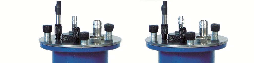
15 Variable Temperature Cell Holders VT Cell Dewar/Cell Holder Assembly Top Plate Layout At the top of the dewar/cell/cuvette holder assembly is a circular plate which carries various connections for vacuum, power cables, thermocouples and liquid delivery tubing. (See Fig 6.) There are seven port/connections through the cell holder/refrigerant chamber top plate. 1. Cell Heater Connection (17). 2. Controlling Thermocouple Port (18). 3. Vacuum Port (19). 4. Connector Port 1 for liquid flow through (20) - (Inlet port). 5. Connector Port 2 for liquid flow through (21) - (Outlet port). 6. Port for additional thermocouple connection (22). 7. Access port for electrical connection of the Specac Spectroelectrochemical Cell (23) Fig 6. Dewar Assembly Top Pressure Plate Port Configuration 13
 in position covering the chamber.")
16 User Manual The main off centre circular area of the top plate is the access hole to the dewar assembly refrigerant chamber itself (24). (Figs 6 and 8. show the dewar stopper bung part (44) in position covering the chamber.) The power cable from the temperature controller for the dewar/cell holder assembly heaters are connected to a four way hermetically sealed socket (17) on this upper circular plate of the dewar assembly. A copper/constantan (Cu/CuNi) T-type thermocouple (25) is used for control measurement of temperature. It passes through port (18) on the top plate and it is permanently fixed in place with its junction end located in the middle of the two cell holder heaters (26). (See Fig 7.) Fig 7. VT Cell GS21525 Cell Holder Detail For Controlling Thermocouple Connection The controlling thermocouple (25) is thus very near to any sample cell held in the cell holder and in this position the temperature monitored will be very close to the actual sample cell temperature when stability is achieved. However, a more precise cell temperature measurement position can be achieved. (See section on Direct Temperature Monitoring from the Sample Cell Section 8, Page 37). 14

17 Variable Temperature Cell Holders The two heaters (26) fitted into the cell holder part/area of the dewar assembly are wired in series with each other and when operating at full rating will dissipate about 40 Watts. These heaters enable the user to vary the temperature of the sample cells over a range from -190 C to +250 C. Note: Liquid samples used in liquid type cells can be operated between temperatures of -70 C to +250 C. Solid samples used in the solids holder GS20610 can be operated over the full temperature range capability from -190 C to +250 C. A specific choice of refrigerant when placed in the dewar chamber (24) determines the actual temperature range capable of being studied in an experiment. Please see an explanation in the Refrigerant section of this manual (Page 22). Vacuum Connection and Blanked Off Ports The vacuum port (19) is for attachment of a vacuum line hose to evacuate the VT Cell Accessory for precise temperature control in operation Fig 8. VT Cell Blanked Off Ports When Supplied as Standard 15
18 User Manual As standard any access port through the top plate that is not utilized during operation of the VT Cell Accessory must be plugged to maintain a vacuum. Both versions of VT Cell P/N s GS21525 and GS21530 are supplied as standard with blanking plugs at port positions (20), (21) and (23) and a blanking rod (27) at port position (22). (See Fig 8.) The type of sample cell for liquids or solids that is to be used within the cell holder part (28 see Fig 9.) of the dewar assembly will determine which of these port positions may be needed. 1) To allow for connectivity of liquid flow to flow cells, the blanking plugs for ports (20) and (21) are removed and the VT Cell Flow Fittings Kit P/N GS20080 is needed to fit to these port positions. (Please see the section on page 21 in this manual for fitting of this kit of parts.) 2) To allow for fitting of the Spectroelectrochemical Cell GS20900 Series, the VT Cell Flow fittings Kit P/N GS20080 must be fitted and the blanking plug for port (23) is removed and replaced with the electrical power cable assembly of parts to attach to the Spectroelectrochemical Cell itself. (Please refer to the specific instruction manual for the Spectroelectrochemical Cell P/N GS20900 for fitting the kit of parts supplied with this cell). 3) To allow for a secondary monitoring thermocouple to be installed and directly attached to a specific liquid sample cell (static or flow) or the solids holder P/N GS20610, the blanking rod (27) is removed from port (22) and replaced with the monitoring thermocouple assembly P/N GS20200 (49). (Please see the section in this manual on Direct Temperature Monitoring from the Sample Cell Section 8, Page 37, for fitting of this thermocouple assembly.) 16
 of the VT Cell Holder Accessories differ between P/N s GS21525 (28) and GS21530 (29). (See Fig 9.")
 of P/N GS21525 and are held in position for good thermal")
19 Variable Temperature Cell Holders 4. Installation of a Sample Cell into the Dewar/Cell Holder Assembly The sample cell holder part (area) of the VT Cell Holder Accessories differ between P/N s GS21525 (28) and GS21530 (29). (See Fig 9.) The sample cell holder part is fitted directly to the base of the stainless steel refrigerant chamber (24) GS21525 GS Fig 9. Cell Holder Parts of VT Cells GS21525 and GS21530 The various liquid and solid sample cell holders are fitted into the cell holder part (28) of P/N GS21525 and are held in position for good thermal contact by tightening of the clamping screw (30). Note: The cell holder part (28) has a flange ring (31) to one side of the cell holder aperture. Sample cells can only be inserted into the aperture of the cell holder from the side opposite to the flange ring (31). The flange ring acts as an end stop for correct positioning of a sample cell within the cell holder part (28). 17
20 User Manual Liquid cuvette sample cells with typical dimensions of 12.5mm long x 12.5mm wide x 41mm high are placed in the cuvette holder part (29) of GS A cuvette can be placed directly into the square slot cavity behind the front clamping plate (32) without the need to remove the clamping plate (32) by its two fixing screws (33). There is a small spring clip behind the clamping plate that pushes against the cuvette and holds it secure in the holder part. Note: Because of the vacuum operation environment needed for precise temperature operation of the VT Cell Accessory, any cuvettes being used in P/N GS21530 must be stoppered/capped to prevent loss of the liquid sample to the vacuum. Fitting Sample Cells into the Dewar/Cell Holder Assembly of P/N GS21525 (See Figs 10, A, B, C, D, E) Before the dewar/cell holder assembly (1) is placed into the vacuum jacket (2), a sample cell should be installed into the cell holder part (28) of VT Cell P/N GS21525 and a cuvette cell into the cuvette holder part (29) of VT Cell P/N GS As mentioned in the introduction a variety of liquid sample cells (static or flow) and a solids holder P/N GS20610 can be used in the VT Cell P/N GS The following procedure is adopted for installation of a sample cell type into the cell holder part (28) Lightly smear the outside of the sample cell with silicone grease. This will ensure good thermal conductivity when clamped in the cell holder part (28) Loosen the M4 x 16mm cap head clamp screw (30) of the cell holder part (28) using the 3mm Allen key supplied until the circular hole of the cell holder aperture is large enough to accommodate the sample cell The cell holder part (28) will only accept sample cells from one direction. Inside the hole there is a circular flange ring (31) which prevents the sample cell from passing all the way through. Take 18
 is facing out of the aperture hole, i.e. this front plate part of the cell is not in contact with the circular flange ring (31).")
 aperture with its monitoring thermocouple well hole connection (34) emerging the")
21 Variable Temperature Cell Holders the sample cell and push it into the cell holder aperture as far as it will go. Ensure that the front plate of the liquid sample cells carrying the monitoring thermocouple well hole (34) is facing out of the aperture hole, i.e. this front plate part of the cell is not in contact with the circular flange ring (31). (See Figs 10A, B, C, D). The solids holder P/N GS20610 is different to the liquid cells in that it is inserted into the cell holder part (28) aperture with its monitoring thermocouple well hole connection (34) emerging the same side as the flange ring (31) of the cell holder part (28). (See Fig 10E.) 4.4 Tighten the clamp screw (30) until the sample cell is firmly held in place and a good thermal contact is made with the cell holder. 34 Fig 10A. GS20500 Series Liquid Cell Installed Fig 10B. GS20560 Series Flow Liquid Cell Installed 19

 such that the aperture of the window")
 should be uppermost in the cell holder such that")
22 User Manual 34 Fig 10C. GS05910 Series High Pressure Liquid Cell Installed Fig 10D. GS20900 Series Spectroelectrochemical Cell Installed Fig 10E. GS20610 Solids Holder Installed Important: When using P/N GS20500 or GS20560 Series cells the sample cell should be inserted in the VT Cell holder part (28) such that the aperture of the window (longest side) is vertical. For all the cells the thermocouple well hole (34) should be uppermost in the cell holder such that the beam from a spectrometer is not obstructed if an optional/spare monitoring thermocouple (49) is used (See Section 8, Page 37).
 and (21).")
23 Variable Temperature Cell Holders Installation of Liquid Flow Sample Cells into the VT Dewar/Cell/Cuvette Holder Assembly If using a flow liquid type cell in the VT Cell Holder P/N GS21525, or a flow cuvette in the VT Cuvette Holder P/N GS21530, then the VT Cell Flow Fittings Kit P/N GS20080 will need to be fitted to the top pressure plate port positions (20) and (21). The flow liquid type cells that can be installed in VT Cell Holder P/N GS21525 and require use of the VT Cell Flow Fittings Kit are:- 1) P/N GS20560/GS20590 Series heatable, sealed and demountable, flow liquid cells. 2) P/N GS05910 Series high pressure, heatable, sealed, flow liquid cells. 3) P/N GS20900 Series heatable, demountable, flow Spectroelectrochemical liquid cells. Fitting of the VT Cell Flow Fittings Kit P/N GS20080 Please see Fig 11. to identify the parts provided from the VT Cell Flow Fittings Kit P/N GS Fig 11. Parts of VT Cell Flow Fittings Kit GS
 is an O-ring seal for the zero dead volume fitting. Two are supplied in the kit. Part (38) is a 50mm long stainless steel blanking rod.")
24 User Manual The contents of the VT Cell Fittings Kit are described as follows: Part (35) is a zero dead volume fitting. Two are supplied in the kit. Part (36) is a flow fitting screw nut. Four are supplied in the kit. Part (37) is an O-ring seal for the zero dead volume fitting. Two are supplied in the kit. Part (38) is a 50mm long stainless steel blanking rod. Two are supplied in the kit. Part (39) is an olive and ferrule set for 1/16 O.D. tubing. Six sets are supplied in the kit. Part (40) is a 130mm long stainless steel 1/16 O.D. flow tube. Two are supplied in the kit. Part (41) is a 40mm long stainless steel 1/16 O.D. flow tube. Two are supplied in the kit. Included in the kit, but not shown, is a length of PTFE tubing, a 9/16 and 5/8 open ended spanner and two 1/4 and 5/16 open ended spanners (wrenches). To fit the VT Cell Fittings Kit of parts the blanking plugs at ports (20) and (21) are removed using the 5/8 spanner. (See Fig 12.) Fig 12. Removal of Blanking Plugs for VT Cell Flow Fitting Kit Use 22
25 Variable Temperature Cell Holders To fit the VT Cell fittings from the GS20080 kit (as shown in Fig 11.) the replacement zero dead volume fittings (35) are screwed into the port positions (20) and (21) onto the top plate via their hexagonal nut head using the same 5/8 spanner. One of the black O-rings supplied (37 - there are two in the GS20080 kit) is placed between the zero dead volume fitting (35) and the top plate to create a vacuum tight seal when the zero dead volume fitting is screwed into position. Connection of Flow Tubes to the Zero Dead Volume Fittings When the zero dead volume fittings (35) have been fitted to the top plate port positions (20) and (21), the 1/16 O.D. flow tubes (40) and (41) can be fitted to allow a liquid to be flowed from the external environment to and from a flow liquid type cell held in the VT Cell holder part (28). The 150mm long flow tubes (40) are fitted to the underside of the zero dead volume fittings (35) to project down for connection to the 1/16 Swagelok union fittings on any flow liquid cell installed in the VT Cell holder part area (28). The 40mm long flow tubes (41) are fitted to the topside of the zero dead volume fittings (35) to connect to any other 1/16 O.D. tubing or the PTFE tubing supplied in the kit, for introduction and return of a liquid from/to the external environment. To seal the flow tubes (40) and (41) into position in the zero dead volume fitting (35), the olive and ferrule sets (39) are used. Take one of the 150mm long tubes (40) and pass it through an olive and ferrule set (39) and a flow fitting screw nut (36) in the direction and sequence of parts as shown from Fig 13. such that the ferrule set and flow fitting screw nut assembly is about 10mm along from one end of the tube (40) Fig 13. Flow Tube, Flow Fitting Screw Nut and Ferrule Assembly 23
, ensuring that the V point of the ferrule is pointing into the zero dead volume fitting (35).")
26 User Manual Then insert this flow tube/flow fitting screw nut/ferrule set assembly into the aperture of the zero dead volume fitting (35) on the underside of the top pressure plate at port position (20), ensuring that the V point of the ferrule is pointing into the zero dead volume fitting (35). Screw tighten the flow fitting screw (36) into the zero dead volume fitting (35) using the 5/16 spanner supplied, thus trapping the ferrule set (39) and the flow tube (40). As the screw nut (36) is tightened the ferrule set is sealed/clamped permanently to the flow tube (40) Repeat this procedure for fitting the other 150mm long flow tube (40) to the zero dead volume fitting (35) on the underside of the top pressure plate at port position (21). Then repeat this procedure for fitting the two 40mm long tubes (41) to the zero dead volume fittings (35) on the top side of the top pressure plate at port positions (20) and (21). The 150mm long tubes (40) that have now been fitted and are projecting downwards can now be connected to the 1/16 Swagelok unions of any flow liquid cell held in the VT Cell holder part (28) by use and sealing of the olive and ferrule sets provided with the Swagelok unions on the flow liquid cell. The finished assembly of parts should look similar to Fig 14, which shows an example of a P/N GS20560 or GS20590 Series flow liquid cell connected to the fitted kit of parts as seen from the underside of the top pressure plate. Fig 14. GS20560 Series Flow Cell Connected to GS20080 Flow Kit 24
27 Variable Temperature Cell Holders Fitting a Blanking Rod at the VT Cell Port Positions (20) and (21) If you wish to install the VT Cell Flow Fittings Kit, but want to operate the VT Cell without a flow cell, there are two stainless steel blanking rods (38) and some olive and ferrule sets (39) supplied with the GS20080 kit that are used to seal the VT Cell jacket for vacuum operation. The rods (38) are passed through the zero dead volume fittings (35) that have been attached. Similar to the procedure for fitting of a flow tube as described previously (see Fig 13.), take a blanking rod (38) and pass it through a flow fitting screw nut (36) and an olive and ferrule set (39) such that the ferrule set is about halfway along the rod. Then insert this assembly into the top side aperture of the zero dead volume fitting (35) ensuring that the V point of the ferrule is pointing into the fitting. Screw tighten the flow fitting screw nut (36) into the top of the dead volume fitting, thus trapping the ferrule set (39) and the blanking rod (38). The 5/16 spanner supplied is used to tighten the flow fitting screw nut (36) into the zero dead volume fitting (35). As the screw nut (36) is tightened the ferrule set (39) is sealed/clamped permanently to the blanking rod and overall the flow fitting becomes sealed for vacuum operation of the VT Cell Accessory. The previous operation for fitting of a blanking rod (38) needs to be done for both flow through port positions (20) and (21) on the top pressure plate of the VT Cell Accessory. When a blanking rod (38) is fitted as described to seal the VT Cell Accessory at these flow port positions, it is not necessary to fit the two further flow fitting screw nuts (36) and ferrule sets (39) to the underside of the zero dead volume fittings (35). 25
. Install a sample cell into the refrigerant dewar/cell holder assembly chamber (See Section 4).")
28 User Manual 5. Installation of the VT Cell into a Spectrometer First, assemble all the components of the VT Cell Accessory. Place windows into the vacuum jacket assembly (See Section 3, pages 10 to 12). Install a sample cell into the refrigerant dewar/cell holder assembly chamber (See Section 4). Place the dewar/cell holder assembly (with a sample cell) into the vacuum jacket assembly. This is done as follows: Check the silicone O-ring (42) that seals between the dewar/cell holder assembly (from P/N GS21525) or dewar/cuvette holder assembly (of P/N GS21530) and the vacuum jacket assembly. (See Fig 15.) Clean it and check the groove (43) in the vacuum jacket assembly for foreign matter. Lightly smear silicone/vacuum grease on the O-ring (42) and replace in its retaining groove (43) Fig 15. Vacuum Jacket Assembly Silicone O-ring for Sealing 26
29 Variable Temperature Cell Holders 5.2. Insert the dewar/cell holder assembly into the vacuum jacket assembly by aligning the locating slot hole (3) in the pressure top plate with the locating pin (5) on the vacuum jacket assembly jacket (2).(See details on page 8.) Note: Ensure that any flow tubes/connections to the sample cells are not trapped and are clear of the inner sides/wall of the vacuum jacket assembly when inserting the dewar/cell holder assembly Screw down the three fixing thumb screws (4) on the top plate to tighten to the vacuum jacket assembly (2). Tighten the screws evenly and sufficiently in rotation to give a vacuum tight seal all around the surface interfaces between the Silicone O-ring (42). Mount the VT Cell Accessory into a Spectrometer This is done as follows: 5.4. Securely mount the whole VT Cell Accessory by use of an appropriate Benchmark baseplate or by use of the affixed 3 x 2 slide mount plate (7). (See pages 8 to 10.) Note: The Solids Holder P/N GS20610 has been designed such that the sample position for a solid is as close to the 3 x 2 backplate (7) as possible. In spectrometers whereby the instruments own 3 x 2 mount baseplate is movable, a slight adjustment in the position of the mount baseplate can bring the sample directly into focus with an improved performance. Use of the Benchmark baseplate as a means of installation provides a more stable support for the whole VT Cell Accessory and as such is recommended in preference to the 3 x 2 slide mount (7) option, if a Benchmark baseplate can be used. Instructions for installation of a particular type of Benchmark baseplate into different spectrometers systems is found in the Benchmark baseplate instruction manual which has been supplied along with this accessory. Please consult this manual for your spectrometer system. 27
30 User Manual Make service connections to the VT Cell. (From controller, vacuum lines, liquid flow lines etc.) 5.5. Connect the 6 way plug cable assembly to the back of the 4000 Series controller. Connect the larger 4 pin Fischer latching plug to the cell holder heaters electrical connection port (17) on the pressure top plate (see Fig 6. page 13), and the smaller 4 pin Fischer plug to the vacuum jacket window heater electrical connection (16) (see Fig 5. page 11.). (The vacuum jacket window heaters may have already had to be connected and switched on when installing hygroscopic windows into the vacuum jacket) Connect a vacuum line (pump and tubing) to the vacuum port (19) on the top plate. (See Fig 6, page 13.) Switch on the vacuum supply. Note: The vacuum line may need independent supporting such that its weight does not move the VT Cell Accessory if the 3 x 2 slide mount plate (7) has been used for installation Connect the 2 pin Fischer plug of the control thermocouple (25), that passes through port (18), to the connection in the back of the 4000 Series controller. (See Fig 6, page 13) Connect liquid flow lines to the top of the flow ports (20 inlet) and (21 - outlet) if using a liquid sample flow cell (P/N GS20560 or GS20590 Series). The Flow Fittings Kit P/N GS20080 must already be installed to do so. For temperature operation and control of the VT Cell Accessory, the instructions from the instruction manual for the 4000 Series temperature controller should now be followed. Temperatures to the sample cells are established by use of specific refrigerants where necessary for sub ambient conditions and/or the cell holder heaters (26). The next section of this instruction manual explains about the refrigerant dewar chamber part of the VT Cell Accessory. 28

31 Variable Temperature Cell Holders 6. Principles of the Refrigerant Chamber The dewar/cell holder assembly (1) of the VT Cell Accessory is a one piece assembly. The integrated design allows for precise control of temperature to the sample cells. The dewar (or refrigerant chamber) is used to contain various refrigerants in order to supply sub ambient temperatures to liquid or solid samples when they are installed within the VT Cell Accessory in their specific sample cell holder. The refrigerant chamber is equipped with two essential component parts; a bung (44) and a mushroom piston assembly (45). The bung is a vented stopper, the vent being a metal hose type tube connector. The mushroom piston is a rod with a circular metal base, the underside being covered with a polyurethane foam disc (46). There are two mushrooms with different sizes of foam disc, a large diameter of 33mm and a smaller diameter of 30mm. (See Fig 16.) Fig 16. VT Cell Bung and Mushroom Piston Assembly When any sub ambient temperature is required the bung and mushroom piston are used to control and contain the refrigerant within the dewar. A sample temperature between -190 C and sub ambient can be achieved by a combination of the correct refrigerant in the dewar (liquid nitrogen), correct choice of mushroom (45) with bung (44) and power from the controller to the cell holder heaters (26). 29
32 User Manual For samples to be analysed at a temperature which is higher than the natural freezing point temperature of the refrigerant, the mushroom (45) is used so that its polyurethane base acts as a partial thermal barrier between the refrigerant in the dewar (24) and the sample cell holder in the sample holder part (28) of the VT Cell Accessory. The sample cell holder may need to reach thermal equilibrium at a temperature considerably higher than that of the refrigerant. The heaters in the cell holder (26) are used to provide higher temperatures to the sample in its holder to compensate (balance) for the lowering of the temperature provided by the refrigerant. However, the mushroom (45) and foam base (46) acts to greatly reduce the rate at which the refrigerant is consumed by heating from the heaters. The heating effect for temperature control is directed preferentially towards the sample itself and allows for a longer lifetime of refrigerant. The bung (44) aids this overall temperature control by preventing air of ambient temperature from heating a lower temperature refrigerant in the dewar. However, the bung (44) allows some of the refrigerant vapour to boil off through the vent tube to prevent build up of pressure within the dewar (24). The bung (44) and mushroom (45) are vital for optimum working efficiency of the dewar. When the mushroom (45) is required in operation, the larger diameter (33mm) foam mushroom operates more efficiently between -100 C to ambient. The smaller diameter (30mm) foam is better between-190 C to -80 C. The base of the dewar (refrigerant chamber 24) is slightly constricted just before the joint with the cell holder part (28) creating a small gap. The constriction prevents the mushroom foam (46) from making intimate contact with the bottom of the dewar during operation. It is therefore recommended that before the mushroom (45) is used this small gap is filled with the stainless steel thermal block disc (47) supplied. This can be done by loosely screwing the stainless steel rod (48) into the disc (47) and gently lowering it down inside the dewar until it reaches the bottom. Unscrew the rod from the disc and remove the rod. (See Fig 17.) If a sample temperature required is close to that of a particular refrigerant the bung (44) is used without a mushroom (45). Output power from the controller can also be reduced. 30
 View to")

33 Variable Temperature Cell Holders Fig 17. Thermal Block Disc and Rod and Cutaway (Section) View to show arrangement of Thermal Block Disc, Mushroom and Bung positions when in the VT Cell Dewar Cell Holder Assembly 31
34 User Manual Refrigerants for the Dewar/Cell Holder Assembly The following table (Table I) is a list of refrigerants that can be used within the dewar of the VT Cell Accessories P/N GS21525 and GS Table I 32 Refrigerant Mixed Temperature (a) C K Ice Water Sodium Chloride/Ice (33g salt/81g ice) Calcium Chloride/Ice (100g salt/81g ice) Hazard Chloroform/Liquid Nitrogen (slush) Fire/Explosion Solid CO2/Ether Fire/Explosion Solid CO2/Acetone Fire/Explosion Solid CO2/Isopropanol Fire/Explosion Toluene/Liquid Nitrogen (slush) Pentane/Liquid Nitrogen (slush) Fire/Explosion Liquid Air (21% oxygen) Isopentane/Liquid Nitrogen (slush) Fire/Explosion Liquid Oxygen Fire/Explosion Liquid Nitrogen Asphyxiation (a) These figures are approximate as actual mixture temperatures are affected by impurities. You should choose the refrigerant mix closest to the temperature you wish to study. e.g. for -50 C use a Chloroform/Liquid Nitrogen mixture which should stabilize at -64 C. Raise the temperature to -50 C using the bung (44) with large mushroom (45) in the dewar and the temperature controller providing heat to the cell holder.
35 Variable Temperature Cell Holders Note: Although the range of the VT Cell is -190 C to +250 C it is not possible to carry out a controlled rate of temperature rise that passes through the ambient point. This is because the rate of refrigerant loss to allow the temperature to go from sub ambient to above ambient cannot be controlled accurately enough to synchronize with the rate of heating supplied by the cell holder heaters (24). Therefore temperature rate rise experiments can only be done within a sub ambient or above ambient range. Operation of the Dewar (Refrigerant Chamber) Safety Note: Risks - Frostbite, Asphyxiation and Explosion When using refrigerants for operation of this accessory you must wear appropriate safety clothing. Specac cannot be held responsible for misuse of the types of refrigerants and refrigerant mixtures recommended for operation. After installation and connection of the services to the VT Cell Accessory in a spectrometer (see section 5.1 to 5.8.) the dewar (24) chamber can be filled with a suitable refrigerant. Important: It is essential that the VT Cell is evacuated to better than 0.05 Torr (0.067mbar) before filling the refrigerant chamber with a refrigerant. If a good vacuum is not achieved before refrigerating, water vapour from the atmosphere would crystallize on the sample cell holder and windows. Place the appropriate mushroom (45) into the refrigerant chamber and then fill with the choice of refrigerant. The bung (44) is put in position with the rod of the piston mushroom (45) running up inside the metal vent tube of the bung (44). Depending on the experiment time it may be necessary to keep the refrigerant level topped up. This is done by removing the bung (44) to gain access to the dewar (24). Tip: It is good practice to have an additional length of rubber tubing attached to the bung vent tube such that any refrigerant boils off 33
36 User Manual away from the top plate of the refrigerant chamber. The rubber tube will also prevent icing up of the bung s metal vent tube. Note: Also, when using liquid nitrogen as the refrigerant, a plastic funnel helps to direct the refrigerant into the dewar only. If the top plate area becomes excessively cold and freezes the sealing silicone O-ring (42) will become rigid and vacuum integrity of the VT Cell could be lost. The following table (Table II) gives the most efficient operating conditions of the VT Cell for various temperature ranges using a mushroom and the refrigerant. In general when only a small temperature rise above that provided by the refrigerant is required, it is advantageous to use the controller at reduced power. From the instructions found in the 4000 Series Controller manual, the parameter OPuL under the SetP parameter list must be set to the appropriate power level as shown in the table for controller power. Most Efficient Operation (Table II) Temp. Range ( C) Mushroom Refrigerant Controller Power Ambient to None None % to + 30 Large (with bung)* Liquid N2 20% to - 80 Small (with bung)* Liquid N2 20% to None Liquid N2 10% *And Thermal Block Disc (47). Warning: At temperatures above ambient the mushroom (45) must be removed. Leaving the mushroom in the dewar (24) will cause damage to the polyurethane foam base (46). N.B. The vacuum must be maintained even when the VT Cell Accessory is used at temperatures above ambient for most efficient temperature control to the sample. 34
37 Variable Temperature Cell Holders 7. VT Cell Operating Parameters on the Dedicated 4000 Series Controller The VT Cell Accessories P/N s GS21525 and GS21530 are provided with their own dedicated 4000 Series Temperature Controller. The 4000 Series Temperature Controller provides heating of a sample cell holder within the VT Cell Accessory. A separate instruction manual is supplied for explanation in operation of the 4000 Series Temperature Controller in conjunction with the VT Cell Accessory. For operation of the VT Cell Accessory the parameters of the 4000 Series Temperature Controller have been factory set as shown on the following page. Not all of the displayable parameters can be changed but have been listed for reference purposes. If you ever need to change a parameter or autotune the controller for a particular temperature range certain parameter settings will be altered. You can get back to original factory settings by reprogramming the controller with these original values. Specifications Accessory Type P/N s GS21525 and GS21530 Voltage 230V 110V 100V Frequency 50HZ 60HZ 50/60HZ Max Power 150W 150W 150W Fuse Rating 1.5A 3A 3A Fuse Type T T T Insulation rating of external circuits (appropriate for single fault condition) = basic insulation and protective (earth) bonding. Humidity operation range 20% to 90% relative humidity noncondensing. 35
38 User Manual Parameter Settings on a 4000 Series Controller for Operation of the VT Cell Accessories P/N s GS21525 and GS21530 Parameter Display (In Green) Parameter Name FiLt Input Filter Time Constant 2.0 OFFS Process Variable Offset 0 PP Primary (Heat) Output 0 Power Pb_P Primary Output 1.8 Proportional Band ArSt Automatic Reset (Integral 1.32 Time Constant) rate Rate (Derivative Time 0.23 Constant) bias Manual Reset (Bias) 25 SPuL Setpoint Upper Limit 250 SPLL Setpoint Lower Limit -190 OPuL Primary (Heat) Output 100 Upper Power Limit Ct l Output 1 Cycle Time 8 PhAl Process High Alarm 250 AHyl Alarm 1 Hysteresis 1 PLA2 Process Low Alarm -190 AHy2 Alarm 2 Hysteresis 1 APt Auto Pre-Tune disa enable/disable PoEn Manual Control select disa enable/disable SPr Setpoint Ramping EnAb enable/disable rp Setpoint Ramp Rate Value 600 SP SP Value 250 SLoc Set-up Lock Code 10 Parameter Factory Set Value 36
39 Variable Temperature Cell Holders 8. Direct Temperature Monitoring from the Sample Cell Holder in GS21525 The standard system controlling thermocouple (25) supplied and fitted measures the temperature of the cell holder area (28) and regulates power to the heaters (24) for precise control of the temperature to the system. After time, the temperature of the whole area will reach stability and it is assumed that the sample temperature will be the same as it local surroundings. However, it is possible to monitor the temperature of the sample cell directly by insertion of an additional monitoring thermocouple P/N GS20200 (49) into the well hole (34) of any of the sample cell holder types that have been installed in the VT Cell holder area (28). This independent monitoring thermocouple (49) is used to measure the actual temperature of the sample, if this is needed to be known, as the position of this thermocouple (49) can be located closer to the actual sample surface itself. The monitoring thermocouple (49) is fitted with a line connector plug (two flat/spade type terminal pins) which can be attached to an independent monitoring readout. 49 This End Fitted With Plug Fig 18. Monitoring Thermocouple GS20200 for VT Cell Accessory An additional monitoring thermocouple (49) can be fitted is as follows: Remove the stainless steel blanking rod (27) from the port position (22) on the circular top plate of the dewar/cell holder assembly (1). The rod (27) is held into the screw nut fitting (50) by a grub screw (51). Unscrew the screw nut fitting (50) from the top plate using the 37
. See Figs 19. and 20. 51 50 27 Fig 19.")

40 User Manual knurled surface and the rod (27) with its own ferrule (52) and sealing O-ring (53) will be removed from the port position (22). See Figs 19. and Fig 19. Screw Nut and Blanking Rod at Monitoring Thermocouple Port Position on the VT Cell Accessory Fig 20. Screw Nut and Blanking Rod Fitting when removed from its Port Position on the VT Cell Accessory 38
41 Variable Temperature Cell Holders 8.2 The blanking rod (27) will need to be removed from the assembly seen in Fig 20. and is to be replaced with the monitoring thermocouple (49). Loosen the M3 x 3mm grub screw (51) using an appropriate Allen key, such that the rod (27), ferrule (52) and O- ring (53) can be slid out of the screw nut (50) Remove the O-ring (53) and ferrule (52) from the blanking rod (27) as these parts are to be reused. Carefully pass the tip of the monitoring thermocouple (49) through the screw nut (50), ferrule (52) and O-ring (53) in the same sequence that these components were used to secure the blanking rod (27). Ensure that there is at least a 200mm length of the thermocouple (49) projecting beyond the O-ring (53) Now carefully pass the tip of the thermocouple (49) from this assembly through the port position (22) until the O-ring (53) and ferrule (52) make contact with the base of the port position access hole. Loosely secure/tighten the screw nut (50) into the port position (22), trapping the O-ring (53) and ferrule (52).The assembly needs to be loose to allow the thermocouple (49) to be slid through the screw nut components and adjusted for its length to fit into the thermocouple well hole (34) of the sample cell holder being used With a particular sample cell holder fitted into position in the cell holder area (28), offer up the tip of the thermocouple (49) to the thermocouple well hole (34). If there is an insufficient length of thermocouple (49) to reach the well hole (34), then this length can be adjusted accordingly by sliding the thermocouple up or down through the loose screw nut (50) connection. Very carefully and gently bend the thermocouple (49) tip about 15mm from its end through an angle of 90 with a bend radius of no less than 15mm. (Gentle radiusing of the bend is important to prevent fracturing the thermocouple sheath) Place the tip of the thermocouple (49) into the well hole (34) of the sample cell holder, ensuring that it also enters at least to a 5 to 6mm depth. A small amount of silicon grease on the tip of the thermocouple (49) can give improved thermal contact. 39
High Temperature High Pressure Cell User Manual
 High Temperature High Pressure Cell User Manual 2I-05850 Issue 16 High Temperature High Pressure Cell User Manual 2I-05850 Issue 16 User Manual High Temperature High Pressure Cell P/N GS05850 CONTENTS
Vacuum Pump Kit User Manual
 Vacuum Pump Kit User Manual 2I-03640-4 Vacuum Pump Kit User Manual 2I-03640-4 Vacuum Pump Kit Vacuum Pump Kit P/N GS03640 CONTENTS 1. INTRODUCTION... 3 2. CHECKLIST OF CONTENTS... 4 3. OPERATION OF THE
Mini-Film Maker Kit User Manual
 Mini-Film Maker Kit User Manual 2I-03970-7 Mini-Film Maker Kit User Manual 2I-03970-7 User Manual Mini-Film Maker Kit P/N GS03970 CONTENTS 1. INTRODUCTION... 3 2. CHECKLIST OF CONTENTS... 5 3. OPERATION
Distinction. D4000 & D4000/EURO Water Still. Assembly and Operating Instructions. 1 Issue 2
 Distinction D4000 & D4000/EURO Water Still Assembly and Operating Instructions 1 Issue 2 Fig. 1 Distinction D4000 & D4000/EURO Water Still 2 Issue 2 Before Use If the equipment is not used in the manner
Eldex Column Heater. Operator s Manual
 Eldex Eldex Column Heater Operator s Manual Eldex Laboratories, Inc. 30 Executive Court Napa, CA 94558 Tel: (707) 224-8800 Fax: (707) 224-0688 www.eldex.com Rev. B: 081700 2000Eldex Laboratories, Inc.
Linkam Scientific Instruments USER GUIDE FDCS196 / THMS350V. Vacuum Stage
 Linkam Scientific Instruments FDCS196 / THMS350V Vacuum Stage USER GUIDE Contents Stages covered by this manual... 3 Before Setting Up Your Equipment... 3 Important Notice... 4 Warranty... 4 Technical
ZD-985 Desoldering Station
 ZD-985 Desoldering Station 2 Contents Contents... 3 Unpacking and Setting Up Your ZD-985 Desoldering Station... 4 Setting Up the Unit... 5 Auto Tip Saver Function... 8 Tips and Techniques... 8 Alloy Melt
Atlas Lightweight Evacuable Pellet Dies User Manual
 Atlas Lightweight Evacuable Pellet Dies User Manual 2I-25410 Issue 2 Atlas Lightweight Evacuable Pellet Dies User Manual 2I-25410 Issue 2 User Manual Atlas Lightweight Evacuable Pellet Dies CONTENTS 1.
73 Series Spectrophotometer. Accessory fitting and operation manual
 73 Series Spectrophotometer Accessory fitting and operation manual 061 672 Safety Please read this information carefully prior to installing or using this equipment. 1. The unit described in this manual
SHOT BLAST CABINET USER INSTRUCTIONS. Model No: CSB20B. Part No: GC05/13
 SHOT BLAST CABINET Model No: CSB20B Part No: 7640110 USER INSTRUCTIONS GC05/13 INTRODUCTION Thank you for purchasing this CLARKE Shot Blast Cabinet which is designed for professional workshop use. Please
ASSEMBLY & OPERATING INSTRUCTIONS
 SD-BASIC SPRAY DRYER ASSEMBLY & OPERATING INSTRUCTIONS 1) Introduction 2) Safety / COSHH 3) General Safety Rules 4) Components Included 5) Packing List 6) Connection to Electrical Supply 7) Assembly and
ACQUITY UPLC HT Column Heater Instructions
 ACQUITY UPLC HT Column Heater Instructions Note: This document is an addendum to Revision C of the ACQUITY UPLC System Operator s Guide. Contents: Topic Page Overview 1 Connecting the cable 4 Installing
Linkam Scientific Instruments USER GUIDE TS1500 TS1200 TS1000. High Temperature Stage
 Linkam Scientific Instruments TS1500 TS100 TS1000 High Temperature Stage USER GUIDE Contents Before Setting Up your Equipment... 3 Important Notice... 4 Warranty... 4 Technical Support... 4 Equipment Maintenance...
Leica EM ACE600 Carbon & Iridium Coating System
 Leica EM ACE600 Carbon & Iridium Coating System Standard Operating Procedure Revision: 1.2 2017-0704 by Michael Paul Overview This document will provide a detailed operation procedure of the Leica EM ACE600
Analox 1000 Series. User Manual. Analox Sensor Technology Ltd. 15 Ellerbeck Court, Stokesley Business Park North Yorkshire, TS9 5PT, UK
 Analox 1000 Series User Manual Analox Sensor Technology Ltd. 15 Ellerbeck Court, Stokesley Business Park North Yorkshire, TS9 5PT, UK T: +44 (0)1642 711400 F: +44 (0)1642 713900 W: www.analox.net E: info@analox.net
Atlas High Temperature Film Maker Accessory User Manual
 Atlas High Temperature Film Maker Accessory User Manual 2I-15800 Issue 15 Atlas High Temperature Film Maker Accessory User Manual 2I-15800 Issue 15 User Manual Atlas High Temperature Film Maker Accessory
TCW 2000 Ice liner refrigerator and freezer PIJ
 TCW 2000 Ice liner refrigerator and freezer OVER VIEW The unique rotomoulded Chest Freezer and inclined Refrigerator with two separate compartments and compressors worldwide Hold over time @ 32 C Hold
Installation Instructions
 Installation Instructions KFN 9855 ide en - CA Installation, repair and maintenance work should be performed by a Miele authorized service technician in accordance with national and local safety regulations
MK 8706 / MB 8706 CONCEALED THERMOSTATIC SHOWER VALVE INSTALLATION GUIDE
 MK 8706 / MB 8706 CONCEALED THERMOSTATIC SHOWER VALVE INSTALLATION GUIDE DIMENSIONS 150mm 55mm 200mm 67mm Hot water ¾ BSP Parallel Cold water ¾ BSP Parallel 160mm x 120mm aperture behind face plate for
INSTALLATION AND COMMISSIONING MANUAL. Neos 100S Integra 20X, 30S, 35X, 40X, 50X
 Installation Truck Refrigeration & Commissioning Manual: INSTALLATION AND COMMISSIONING MANUAL for Neos 100S Integra 20X, 30S, 35X, 40X, 50X Direct Drive Refrigeration Units 2017 Carrier Corporation Printed
U tube models PTU 09, 12, 15, 25, 30, 35, 40, 45. single linear tube models PTS 09, 12, 15, 25, 30, 35, 40, 45
 U tube models PTU 09, 2, 5, 25, 30, 35, 40, 45 & single linear tube models PTS 09, 2, 5, 25, 30, 35, 40, 45 installation, servicing & operating instructions INSTALLATION, SERVICING AND OPERATING INSTRUCTIONS
5COM52XXD Series Fan. Owner s Guide and Installation Manual. UL Model NO. : 5COM52XXD
 Owner s Guide and Installation Manual 5COM52XXD Series Fan UL Model NO. : 5COM52XXD Attach sales receipt to this card and retain as your proof of purchase DATE OF PURCHASE: MODEL NUMBER: RETAILER NAME:
INVERTER SPLIT - TYPE
 INVERTER SPLIT - TYPE ISSUE No 2 DATE 04/09/08 P/No 2020323A2868 CONTENTS SAFETY PRECAUTIONS Warning 2 Operating temperature 2 BEFORE INSTALLATION Tools needed for installation 3 Items required for installing
EXFG Oxygen Analyzer System. Installation Guide. EXFG Probe. ABB Process Analytics
 EXFG Oxygen Analyzer System Installation Guide EXFG Probe ABB Process Analytics ABB PROCESS ANALYTICS The Company ABB Process Analytics specializes in the engineering, manufacture, sale and support of
Linkam Scientific Instruments
 Probe Systems for Microscopy and Spectroscopy There are many applications that require the measurement of electrical parameters whilst making microscopic or spectroscopic observations. Linkam have designed
Quartz. Digital. Bath with bath waste filler. Quartz Digital Bath with bath waste filler installation instuctions page 1
 Quartz Digital Bath with bath waste filler The Waste Electrical and Electronic Equipment (Producer Responsibility) Regulation 2004 This product is outside the scope of the European Waste Electrical and
Basin Mixer. Installation & Aftercare Instructions. Please retain for future reference.
 Basin Mixer Installation & Aftercare Instructions Please retain for future reference. This guide covers the installation of all basin mixer varients. Please select the installation diagram suited to the
Heat Exchanger Block Replacement Instructions
 Series 1-4 Gas-fired water boiler Heat Exchanger Block Replacement Instructions Ultra-80 S1-4 Heat Exchanger Block Replacement Kit, Part No. 383-500-773 Ultra-105 S1-4 Heat Exchanger Block Replacement
MAINTENANCE MANUAL TAIYO SEIKI CO., LTD.
 MAINTENANCE MANUAL TAIYO SEIKI CO., LTD. Introduction This Maintenance Manual explains how to replace and adjust the major components of the Automatic Taping Machine when required in daily operation.
HW-17 Record Cleaning Machine Setup and Instruction Manual
 HW-17 Record Cleaning Machine Setup and Instruction Manual VPI Industries, Inc., 77 Cliffwood Ave. #3B, Cliffwood, NJ 07721 Phone: 732-583-6895, Email: Sales@vpiindustries.com http://www.vpiindustries.com
C-IV 60 CEILING FAN READ AND SAVE THESE INSTRUCTIONS. FAN RATING AC 120V. 60Hz
 C-IV 60 CEILING FAN READ AND SAVE THESE INSTRUCTIONS FAN RATING AC 120V. 60Hz Please do not use any electric or battery powered tools in the assembly and installation of this or any Matthews Fan Company
50 Disassembly and assembly Cab and its attachments
 When adjustment is needed after performing check in step 8; 3) Close front window assembly (1). 4) Loosen locknuts (26) of right and left rubber stoppers (24) and move the stoppers backward so that front
CEILING FAN OWNER'S MANUAL
 CEILING FAN OWNER'S MANUAL READ AND SAVE THESE INSTRUCTIONS MODEL: 52-135-5WA-13 FAN RATING AC 120V. 60Hz CUL LISTED MODEL : AC-552OD 1. TOOLS AND MATERIALS REQUIRED Philips screw driver Blade screw driver
Variable Temperature Microprobe Systems
 Variable Temperature Microprobe Systems the world s resource for variable temperature solid state characterization 2 The Variable Temperature Microprobe System The variable temperature microprobe system
Bench-Top Vacuum Oven with 28 segments programmable controller
 Bench-Top Vacuum Oven with 28 segments programmable controller DZF-6000F Series Vacuum Oven MTI Corporation www.mtixtl.com 1 Safety notes DZF Vacuum Oven Please read the following safety notes carefully
60" Lyndon Patio. Instruction Manual Customer Service :30 AM to 5:00 PM EST, Monday - Friday A Kichler Decor ceiling fan
 60" Lyndon Patio TM 310140 A Kichler Decor ceiling fan Includes wall mount control system Kichler Lighting 7711 East Pleasant Valley Road P.O. Box 318010 Cleveland, Ohio 44131-8010 Instruction Manual Customer
KINNEY OIL MIST ELIMINATORS
 KINNEY OIL MIST ELIMINATORS Models: A B, B1 & B2 C1 D & D1 Instruction Manual 1855-1 Revision 12/01 TABLE OF CONTENTS DESCRIPTION... 1 OPERATION... 1 ELEMENTS... 2 OIL RETURN METHODS... 3 DIRECT DRAIN
PRELIMINARY INSTALLATION. Operation & Service Manual. Carrier Transicold Europe 03/09/07 Viento - Installation/Rev- #1/56
 INSTALLATION Carrier Transicold Europe 03/09/07 Viento - Installation/Rev- #1/56 INSTALLATION Table of content Introduction...4 Preparation before installation...5 Vehicle partition... 6 Box preparation...7
INSTALLATION MANUAL SPLIT TYPE ROOM AIR CONDITIONER (PART NO )
") SPLIT TYPE ROOM AIR CONDITIONER INSTALLATION MANUAL (PART NO. 9312791019-01) This air conditioner uses new refrigerant HFC (R410A). The basic installation work procedures are the same as conventional refrigerant
SPLIT TYPE ROOM AIR CONDITIONER INSTALLATION MANUAL (PART NO. 9312791019-01) This air conditioner uses new refrigerant HFC (R410A). The basic installation work procedures are the same as conventional refrigerant
Vacmobile 20/2. Instruction manual OPERATION & SERVICE
 This instruction manual provides general instructions for the Vacmobile 20/2 vacuum system. This machine may use either the Becker U4.20 or the PVR EM 20/B vacuum pump. Service information specific to
52 CEILING FAN READ AND SAVE THESE INSTRUCTIONS FAN RATING AC 120V.
 Irene 52 CEILING FAN READ AND SAVE THESE INSTRUCTIONS FAN RATING AC 120V. 60Hz TABLE OF CONTENTS Tools and Materials Required... 1 Package Contents... 1 Safety Rules... 2 Mounting Options... 3 Hanging
NMR SAMPLING ACCESSORIES CLEANING NMR SAMPLE TUBES
 CLEANING NMR SAMPLE TUBES It is important to understand that NMR sample tubes are NOT laboratory glassware and should not be treated as such. Because of the precision tolerances and the very thin wall
Grant Spira 6-26kW and 9-36kW Wood Pellet Boilers
 ADDENDUM to INSTALLATION INSTRUCTIONS for Grant Spira 6-26kW and 9-36kW Wood Pellet Boilers DOC42-01/02 Rev03 - December 2014 ATTENTION INSTALLERS - UPDATED INFORMATION! The Grant Spira condensing wood
Water Distiller Service Manual
 Water Distiller Service Manual Water Distiller Service Manual L70478WT 2008 Regal Ware, Inc. Table of Contents RECOMMENDED TOOLS... 2 GENERAL INSPECTION...3 BOILING CHAMBER TROUBLESHOOTING & REPAIRS Description...
1. SAFETY RULES WARNING WARNING. 8. Avoid placing objects in the path of the blades.
 1 1. SAFETY RULES 1. To reduce the risk of electric shock, insure electricity has been turned off at the circuit breaker or fuse box before beginning. 2. All wiring must be in accordance with the National
Specifications 3. Bladder 5. Chimney 12. Air Supply 12. Anti-Rollout Device and Ash Auger Tube 14. Timer 15
 TABLE OF CONTENTS Page No. Specifications 3 Bladder 5 Fire Door 7 Chimney 12 Air Supply 12 Anti-Rollout Device and Ash Auger Tube 14 Timer 15 Supply Line and Return Line Threaded Connectors 15 Low Water
Technology for Vacuum Systems. Instructions for use
 page 1 of 8 Technology for Vacuum Systems Instructions for use GKF 1000i Cold trap page 2 of 8 Content Safety information!...3 General information...3 Intended use...3 Setting up and installing the cold
Technical Data TYPE T14 & T14D TEMPERATURE PILOT SPENCE ENGINEERING COMPANY, INC. 150 COLDENHAM ROAD, WALDEN, NY SD 4511A T14 PILOT
 Technical Data SD 4511A SPENCE ENGINEERING COMPANY, INC. 150 COLDENHAM ROAD, WALDEN, NY 12586-2035 TYPE T14 & T14D TEMPERATURE PILOT PRINTED IN U.S.A. SD 4511A/9811 5 13 /16 D 4 7 /8 1 13 /16 T14 PILOT
Variable Temperature Options for Optical Experiments
 Variable Temperature Options for Optical Experiments the world s resource for variable temperature solid state characterization 2 The Variable Temperature Options for Optical Experiments MMR Technologies
Owner s Guide and Installation Manual
 For Your Records and Warranty Assistance For reference, also attach your receipt or a copy of your receipt to the manual. Model Name Type 2A Models Owner s Guide and Installation Manual Model No. Date
INSTRUCTION MANUAL (English version) Water still
 Water still") INSTRUCTION MANUAL (English version) Water still Model : Brand : W4000 Merit Merit Water Still W4000 & W4000/EURO Cooling water inlet Condenser Constant level control Boiler Thermostat reset buttons To
INSTRUCTION MANUAL (English version) Water still Model : Brand : W4000 Merit Merit Water Still W4000 & W4000/EURO Cooling water inlet Condenser Constant level control Boiler Thermostat reset buttons To
1.0 Denton Thermal Evaporator
 1.0 Denton Thermal Evaporator View port shutter knob Touch screen View port Vacuum chamber Thickness monitor EMO Switch 1.1 Introduction Figure 1: Denton Thermal Evaporator. Denton Thermal Evaporator is
Cooled Incubators Series 1, 3 & 4. Instruction Manual
 Cooled Incubators Series 1, 3 & 4 Instruction Manual Instruction Manual for LMS Cooled Incubators Series 1, 3 & 4 Series 1 Models 305-60 litre capacity 303-180 litre capacity 250-250 litre capacity Series
TK-1801, TK-1811 TK-1801, TKR-1811
 TK-1801, TK-1811 TK-1801, TKR-1811 Pneumatic Zero Energy Band Room Thermostats General Instructions APPLICATION For proportional control of pneumatically-operated sequenced heating and cooling valves and/or
42 Kevlar. Instruction Manual. Kichler Lighting 7711 East Pleasant Valley Road P.O. Box Cleveland, Ohio
 42 Kevlar Kichler Lighting 7711 East Pleasant Valley Road P.O. Box 318010 Cleveland, Ohio 44131-8010 Customer Service 866.558.5706 8:30 AM to 5:00 PM EST, Monday - Friday Instruction Manual 1 1. SAFETY
5YK60XXX Series Fan. Owner s Guide and Installation Manual. CUL Model NO. : 5YK60XXX
 Owner s Guide and Installation Manual 5YK60XXX Series Fan CUL Model NO. : 5YK60XXX Attach sales receipt to this card and retain as your proof of purchase DATE OF PURCHASE: MODEL NUMBER: RETAILER NAME:
MNEFDD54 & MNBCDD54 GALVANIZED WALL FANS Installation, Operation, and Maintenance Instructions
 FARM PRODUCTS DIVISION MEMBER OF AMCA AMERICAN COOLAIR CORPORATION P.O. BOX 2300 JACKSONVILLE, FLORIDA 32203 PHONE (904) 389-3646 FAX (904) 387-3449 E-MAIL - fans@coolair.com MNEFDD54 & MNBCDD54 GALVANIZED
DART-Thermo LTQ/Orbitrap Interface Manual
 DART-Thermo LTQ/Orbitrap Interface Manual For Thermo LTQ (Orbitrap) Velos, LTQ Orbitrap XL, LTQ Ion Trap, Exactive High Performance, and all other instruments that utilize the Ion Max Source Version 20120423
DLCLRA. INSTALLATION INSTRUCTIONS Outdoor Unit Single Zone Ductless System Sizes 36 to 58 TABLE OF CONTENTS
 DLCLRA INSTALLATION INSTRUCTIONS Outdoor Unit Single Zone Ductless System Sizes 36 to 58 Fig. 1 - Size 36 TABLE OF CONTENTS PAGE SAFETY CONSIDERATIONS... 2 PARTS LIST... 3 SYSTEM REQUIREMENTS... 4 WIRING...
60" Tulle PatioTM. Instruction Manual. A Kichler Select ceiling fan
 60" Tulle PatioTM A Kichler Select ceiling fan cul Certified for Wet Location Kichler Lighting 7711 East Pleasant Valley Road P.O. Box 318010 Cleveland, Ohio 44131-8010 Customer Service 866.558.5706 8:30
W A T L O W. Straight Resistance Wire. Welded End Cap
 W A T L O W The versatile Watlow cable heater can be formed to a variety of shapes as dictated by its many applications. Cable heaters are small diameter, high performance units, fully annealed and readily
CryoFit. Handling of Flow Cell and Capillaries. User Guide. Version 002
 CryoFit Handling of Flow Cell and Capillaries User Guide Version 002 Copyright by Bruker BioSpin NMR GmbH. All rights reserved. No part of this publication may be reproduced, stored in a retrieval system,
BASIN MIXERS INSTALLATION & AFTERCARE INSTRUCTIONS
 BASIN MIXERS INSTALLATION & AFTERCARE INSTRUCTIONS This guide covers the installation of all Tavistock basin mixer varients. Please select the installation diagram suited to the basin mixer you have purchased.
S Y D. HWP 35, 47, 58 (c/w EC Motor & UC7 Controller) Ducted Water Cooled R410A Packaged Air Conditioner. Installation & Maintenance
 Ducted Water Cooled R410A Packaged Air Conditioner. Installation & Maintenance") HWP 35, 47, 58 (c/w EC Motor & UC7 Controller) Ducted Water Cooled R410A Packaged Air Conditioner Installation & Maintenance Fig. 1 Nomenclature Nomenclature e.g. H W P 3 5 C K Series Size Type S Y D GENERAL
HWP 35, 47, 58 (c/w EC Motor & UC7 Controller) Ducted Water Cooled R410A Packaged Air Conditioner Installation & Maintenance Fig. 1 Nomenclature Nomenclature e.g. H W P 3 5 C K Series Size Type S Y D GENERAL
Owner s Guide and Installation Manual
 For Your Records and Warranty Assistance For reference, also attach your receipt or a copy of your receipt to the manual. Model Name Type 2 Models Owner s Guide and Installation Manual Model No. Catalog
FOOD WASTE DISPOSER INSTALLATION AND USE MANUAL
 FOOD WASTE DISPOSER INSTALLATION AND USE MANUAL English only (Australia and New Zealand) 1a 1 1b 1 1c 11 3 1 17 3 13 4 1 7 14 1 0 1 7174 Rev C www.insinkerator.com 01 InSinkErator, a business unit of Emerson
Laboport Chemically-resistant Laboratory Pumps and Systems
 Operating Instructions Read and observe these Operating Instructions! Laboport Chemically-resistant Laboratory Pumps and Systems N 810 FT.18 N 820 FT.18 N 840 FT.18 N 840.1.2 FT.18 N 810.3 FT.18 N 820.3
A AD Oil burners fuel unit. deltapumps.com. DE A-AD_en_0709.pdf Page 1/1
 A AD Oil burners fuel unit deltapumps.com DE116-0709 A-AD_en_0709.pdf - 16.11.09 Page 1/1 Oil burners fuel unit Type A, AD 1- Applications The DELTA aluminium fuel unit type A is an efficient and modern
Service Instructions
 BASIC EXCELLENT PERFECT U Universal ovens I Incubators S Sterilisers Service Instructions Mo Tu We Th Fr Sa Su t3 on off h t2 t1 t4 loop 4 3 2 1 STERI DEFRO C MIN MAX C IN 1 IN 2 OUT IN 1 IN 2 OUT % rh
OPTIONAL SPRING MTG HANGING CENTRES WATER CONN'S: TWO BSP MALE. 19 mm (3/4") ELECTRICAL CONDUIT HOLES ACCESS PANEL OUT (WATER) IN 485 MOUNTING
 ELECTRICAL CONDUIT HOLES ACCESS PANEL OUT (WATER) IN 485 MOUNTING") HWP 117 225 Ducted Water Cooled R410A Packaged Air Conditioner Dimensions (mm) Fig. 1 HWP 117 60 1210 SPRING MOUNTING CENTRES 690 (HEIGHT = 370) FILTER BOX PROJECTION Net Weight 105 kg Installation & Maintenance
HWP 117 225 Ducted Water Cooled R410A Packaged Air Conditioner Dimensions (mm) Fig. 1 HWP 117 60 1210 SPRING MOUNTING CENTRES 690 (HEIGHT = 370) FILTER BOX PROJECTION Net Weight 105 kg Installation & Maintenance
569, 570, 571, 572 Series
 Please read and save this Repair Parts Manual. Read this manual and the General Operating Instructions carefully before attempting to assemble, install, operate or maintain the product described. Protect
Mix Boiler & Font Range ( #, #, #, , )
") Mix Boiler & Font Range (1000870#, 1000871#, 1000880#, 1000878, 1000879) Service Manual Marco Beverage Systems Ltd. 63d Heather Road, Sandyford Industrial Estate, Dublin 18, Republic of Ireland Ireland
Mix Boiler & Font Range (1000870#, 1000871#, 1000880#, 1000878, 1000879) Service Manual Marco Beverage Systems Ltd. 63d Heather Road, Sandyford Industrial Estate, Dublin 18, Republic of Ireland Ireland
Vacuum Equipment. Manifolds. Traps. Pumps. Adapters. Easy to assemble Ace-Safe connector versions. O-Ring connections. Added safety and versatility
 Adapters g Pumps g Traps Vacuum Equipment Manifolds Easy to assemble Ace-Safe connector versions O-Ring connections Added safety and versatility Comp act 2 Vacuum Manifolds 7818 ACCESSORIES 7818 Vacuum
Installation Instructions Solar Controller Kit (Part Number AQ )
") Installation Instructions Solar Controller Kit (Part Number AQ7014151) This solar controller kit must be installed and serviced by an authorised person. Please leave this guide with the householder. The
Installation Instructions Solar Controller Kit (Part Number AQ7014151) This solar controller kit must be installed and serviced by an authorised person. Please leave this guide with the householder. The
S D HWP 77, 96. Ducted Water Cooled R410A Packaged Air Conditioner. Installation & Maintenance. Fig. 1 Nomenclature. Fig.
 HWP 77, 96 Ducted Water Cooled R410A Packaged Air Conditioner Installation & Maintenance Fig. 1 Nomenclature Nomenclature e.g. H W P 7 7 C K Series Size Type S D GENERAL HWP - A general designation which
VD 53 - Vacuum drying oven for non-flammable solvents
 Vacuum drying ovens VD 53 - Vacuum drying oven for non-flammable solvents The VD series offers safe drying with homogenous temperature distribution, thanks to its APT.line air jacket system. ptimum heat
Oil burners fuel unit with solenoid valve
 Oil burners fuel unit with solenoid valve Type VM www.deltapumps.com VM1 - VM4U flanged Certified Quality System Printed in Germany VM_e.pdf - 18.05.08 Page 1/6 Oil burners fuel unit with solenoid valve
MIX Boiler & Font Range Service Manual
 MIX Boiler & Font Range Service Manual 1000870# 1000871# 1000875# 1000880# 1000887# 1000878 1000879 2300268 www.marcobeveragesystems.com Ireland Tel: +353 (1) 295 2674 UK Tel: +44 (0207) 2744577 Service
Chemical resistant Vacuum Pumps
 Chemical resistant Vacuum Pumps C300 / C400 / C410 / C510 / C600 / C610 English Operating Manual WIGGENS labortechnik GmbH Mühsamstrasse 3610249 Berlin Germany Fon:+49 30 42105470 Fax:+49 30 42105971 E-Mail:
INSTALLATION INSTRUCTION
 INSTALLATION INSTRUCTION FLOOR /CEILING INDOOR UNIT MODEL: SMUL 12,18,24,30,36,48,60 Read this instructions carefully before installation. P. 12 P. 01 Dimemsion RHEEM REV 01 P. 02 P. 11 Detaching the mounting
INFRARED IP55 HEATER INSTRUCTIONS FOR: MODEL:- QZWP45N 1. SAFETY INSTRUCTIONS
 INSTRUCTIONS FOR: INFRARED IP55 HEATER MODEL:- QZWP45N Thank you for purchasing a Consort Claudgen product. Manufactured to a high standard this product will, if used according to these instructions and
Installation Manual Mopar Engine Compartment Upgrade Kit
 Installation Manual 64-75 Mopar Engine Compartment Upgrade Kit Congratulations... You have just purchased the highest quality, best performing A/C system upgrade ever designed for your Classic Vehicle.
W A T L O W. Straight Resistance Wire. Welded End Cap
 W A T L O W The versatile Watlow cable heater can be formed to a variety of shapes as dictated by its many applications. Cable heaters are small diameter, high performance units, fully annealed and readily
Owner s Guide and Installation Manual
 For Your Records and Warranty Assistance For reference, also attach your receipt or a copy of your receipt to the manual. Model Name Type 2A Models Owner s Guide and Installation Manual Model No. Date
3MAVR60XX Series Fan. Owner s Guide and Installation Manual. UL Model NO. : 3MAVR60XX
 Owner s Guide and Installation Manual 3MAVR60XX Series Fan UL Model NO. : 3MAVR60XX Attach sales receipt to this card and retain as your proof of purchase DATE OF PURCHASE: MODEL NUMBER: RETAILER NAME:
Model No: Little Devil II (inc ss)
") GAS HEATER Model No: Little Devil II (inc ss) PART NO: 6926020, 6926025 (SS) OPERATION & MAINTENANCE INSTRUCTIONS LS1213 INTRODUCTION Thank you for purchasing this CLARKE Gas Heater. Before attempting
GAS HEATER Model No: Little Devil II (inc ss) PART NO: 6926020, 6926025 (SS) OPERATION & MAINTENANCE INSTRUCTIONS LS1213 INTRODUCTION Thank you for purchasing this CLARKE Gas Heater. Before attempting
HX Field Replacement Kit
 Quantity Kit Part Number Description PE 110 Natural Gas Stainless Steel Condensate Pan PT 110 Natural Gas Polypropylene Condensate Pan Model PE 110 LP Stainless Steel Condensate Pan PT 110 LP Polypropylene
Please read and save these instructions. Should you have any questions or difficulty installing your fan, call us first!
 IC/Air2 and IC/Air3 Installation Instructions and Owners Manual Please read and save these instructions. Should you have any questions or difficulty installing your fan, call us first! Customer Service
Karlsruher Glastechnisches Werk KGW-ISOTHERM
 Karlsruher Glastechnisches Werk KGW-ISOTHERM Germany 76185 Karlsruhe Gablonzer Straße 6 Tel. 0049 / 721 / 95897-0 Fax. 0049 / 721 / 95897-77 E-Mail: info@kgw-isotherm.de Internet: kgw-isotherm.com Operating
MC2000 OPERATING AND CALIBRATION INSTRUCTIONS
 MC2000 OPERATING AND CALIBRATION INSTRUCTIONS CONTENTS 1 - CERTIFICATE OF CONFORMITY... 3 2 - PRESENTATION... 4 2. 1 - GENERAL... 4 2. 2 - CHARACTERISTICS... 4 2. 3 - OPERATING PRINCIPLE... 5 2. 3. 1 -
CEILING FAN OWNER'S MANUAL
 CEILING FAN OWNER'S MANUAL MODEL: Pelham HVFC# 2299 Old Bronze Satin Nickel Polished Nickel READ AND SAVE THESE INSTRUCTIONS FAN RATING AC 120V. 60Hz. CUL LISTED MODEL: AC-554SY05-7S WEIGHT OF THE FAN:
DC Heat Recovery Unit MVHR Wholehouse heat recovery unit
 DC Heat Recovery Unit MVHR Wholehouse heat recovery unit Stock Ref. N DC Heat Recovery Unit MVHR 443423 Installation, Maintenance & Users Instructions PLEASE READ INSTRUCTIONS IN CONJUNCTION WITH ILLUSTRATIONS.
INSTALLATION. Glass Panel Doors (select models) CAUTION
 CAUTION") Location Do not install refrigerator near oven, radiator or other heat source. If not possible, shield refrigerator with cabinet material. Do not install where temperature falls below 55 F (13 C) or rises
Location Do not install refrigerator near oven, radiator or other heat source. If not possible, shield refrigerator with cabinet material. Do not install where temperature falls below 55 F (13 C) or rises
MONITOR REFERENCE SERIES
 MONITOR REFERENCE SERIES o w n e r s m a n u a l Contents Introduction 1 Positioning 2 AV Positioning 2 2 Channel Positioning 3 Spike Fixing 3 Wiring Configurations 4 Port Bungs 5 Amp Panel & Controls
Glendale 52 in Ceiling Fan Owner's Manual. Glendale Ventilador de Techo de 1.32 m Manual del Propietario
 Glendale 52 in Ceiling Fan Owner's Manual Glendale Ventilador de Techo de 1.32 m Manual del Propietario Hampton Bay Lifetime Motor Warranty The retailer warrants the fan motor to be free from defects in
Installation and Operation Manual For Hunter Ceiling Fans
 Installation and Operation Manual For Hunter Ceiling Fans 1 2 CONGRATULATIONS! Your new Hunter ceiling fan is an addition to your home or office that will provide comfort and performance for many years.
Conical Fermenter. Instructions
 Conical Fermenter Instructions What s in the Box?: 01. AIRLOCK Rubber Bung Fermenter lid Fermenter Body CONTENTS WHAT S IN THE BOX...P1 ANATOMY/SCHEMATICS...P2 FERMENTING WITH THE STANDARD FERMENTER...P.5
ROTARY VACUUM EVAPORATOR RVO 004
 INGOS Ltd. ROTARY VACUUM EVAPORATOR RVO 004 User manual PRAGUE April 11 2006 INGOS Ltd. Laboratory Instruments division Page 1 Producer : Laboratory Instruments division of INGOS Ltd. Supplier and service
MODEL A-316 CARBON MONOXIDE (CO) MONITOR AND ALARM FOR COMPRESSED AIR TESTING
 MONITOR AND ALARM FOR COMPRESSED AIR TESTING") MODEL A-316 CARBON MONOXIDE (CO) MONITOR AND ALARM FOR COMPRESSED AIR TESTING FOR OPERATION FROM 115 AC POWER Andersen Medical Gas 12 Place Lafitte Madisonville, LA 70447 http://www.themedicalgas.com 1-866-288-3783
MODEL A-316 CARBON MONOXIDE (CO) MONITOR AND ALARM FOR COMPRESSED AIR TESTING FOR OPERATION FROM 115 AC POWER Andersen Medical Gas 12 Place Lafitte Madisonville, LA 70447 http://www.themedicalgas.com 1-866-288-3783
LIMITED LIFETIME WARRANTY
 LIMITED LIFETIME WARRANTY To obtain Service, please contact or call Turn of the Century Service Department: 1-800-887-6326, 9 a.m.- 5 p.m. central time. Model No.: # 355-6782 The limited lifetime warranty