Atlas Model SF Corrosive Fog/Humidity Cabinet
|
|
|
- Sheryl McDowell
- 5 years ago
- Views:
Transcription

 327-4520")
1 Atlas Model SF Corrosive Fog/Humidity Cabinet INSTRUCTION MANUAL Doc. P/N Rev SAFETY... 5 Atlas Material Testing Technology LLC 4114 North Ravenswood Avenue Chicago, IL USA Phone: (773) Fax: (773)
2 1.0 SAFETY SETUP INSTALLATION GUIDELINES What is Needed for Chamber Installation Drain Connection (Customer supplied & installed) Vent Connection Compressed Air Connection Water Supply Requirements and Connection Electrical Connection Level Floor Access Utility Services Testing Lab Temperature and Humidity Floor Space COMPONENTS & CONTROLS Gallon Solution Storage & Mixing Reservoir Stand for Solution Reservoir liter ( 55-gallon) Solution Tank Solution Tank Drain Assembly Air Agitation Regulator and Gauge Mixing Tank Air Sparger (agitator) Solution Feed Assembly for Dispersion Tower - Tank End Solution Tank Filter Assembly Exposure Zone Interior Chamber Vent Port Fog Dispersion Tower Assembly - Vertical Fog Dispersion Tower Assembly - Horizontal Exposure Zone Drain Fitting Dry Bulb RTD Temperature Probe Wet Bulb RTD Temperature Probe Purge Bulkhead Fitting Bulkhead Union, Polypro, 3/8 Tube x 3/8 Tube Racks, Support Racks, Plastisol Coated Support Bar, Plastisol Coated Chamber Exterior Humidifying Tower Assembly Chamber Heaters Sight Gauge Fittings Sight Gauge Water Jacket Fill Fitting Salt Solution Solenoid Electrical Panel Doc. P/N Rev. 4.0
3 3.4 Chamber Cover Assembly PVC Cover Hinge Hardware Lid Safety Switch Assembly Cover lifters Gas Shocks Air Cover Lifter Assembly for SF2000, SF3600 and SF OPERATION Startup Quick-Startup Procedures Basic Operation Salt Fog Cycle Intermediate Operation Chamber Capabilities Component Manual Ball Valves Solenoid Valve Assignments Dispersion Tower Assembly Installation Advanced Operation Temperature Controls CALIBRATION MAINTENANCE Check Before Each and Every Test: Routine Monthly Maintenance Annual Service TROUBLESHOOTING Collection Rates Fog Dispersion Control and Controllers Determining & Measuring Collection Rates Basic Troubleshooting Guide General Special Note on Solution Purity: Filter, Spray Nozzle Troubleshooting Contents No Fog Low Collection Rates High Collection Rates Uneven Collection Rates Low Relative Humidity No Heat in Humidifying Tower Cover Bounces Cloudy Humidifying Tower Incorrect ph level Inconsistent Air Pressure in Humidifying Tower Humidifying Tower Fills up with Water Over the Float Switch Salt Settles in Bottom of Salt Solution Reservoir Temperature Controller Data Sheet OMRON E5CS-X Doc. P/N Rev. 4.0
4 8.0 SPARE PARTS PRINTS AND DRAWINGS Electrical Plumbing Layout ATO-Fill layout LC Jet Exhaust Recirculation System LC Layout Drawing for all models GLOSSARY WARRANTY Doc. P/N Rev. 4.0
5 1.0 Safety This section defines safety symbols that appear throughout this manual. It also provides a list of operational precautions and guidelines to observe for safely operating the salt fog corrosion chamber. 1.1 Safety Symbols HIGH VOLTAGE! HIGH VOLTAGE! Indicates that ignoring the instructions may lead to electrical shock and possible injury. DANGER! DANGER! Indicates that ignoring the instructions may lead to hazardous conditions for the operator. WARNING! WARNING! Indicates that ignoring the instructions may damage the cabinet or affect test results. NOTE! NOTE! Indicates operational hints and useful information. 1.2 Operational Precautions. This list contains the safety precautions that must be followed to safely operate the SALT FOG CORROSION CABINET. Cover Each Salt Fog Corrosion Chamber has an exposure chamber cover. It is shipped on the cabinet in a closed position. Always open the cover by lifting the center of the handle. Failure to do so can damage the cover and void any warranty the cover may have. Drains Cabinet drains must be laid over the facility drain and not directly connected into the facility drain. This will prevent backpressure from forcing drainage back into the exposure zone. Exhaust Cabinet exhaust must be vented to the outside of the customer s facility. NEVER directly connect multiple corrosion cabinets to the same vent. If multiple corrosion cabinets (or any other machinery) are vented together, the exhaust from one cabinet(machine) can leak into another, causing harm to the test as well as other cabinet. Doc. P/N Rev. 4.0
6 2.0 SETUP INSTALLATION GUIDELINES Prior to the arrival (or relocation) of the Salt Fog Corrosion Cabinet, there are electrical, environmental, air, water, floor space, and accessibility considerations. All connections and tests of service should be made prior to powering up the chamber. 2.1 What is Needed for Chamber Installation Qualified electrician for electrical connection Plumber for drain, air and water connections HVAC installer (or other qualified personnel) for chamber vent connection Level floor Access to the outside via a roof vent or side wall vent Floor drain Pressurized kpa (25-80 psi) ASTM D1193 reagent grade type IV water. Best chamber performance is obtained at the higher-pressure ratings. Clean dry compressed air regulated to kpa (30-50 psi). Customer specified electric power from a lockable disconnect with appropriate amount of electric cord and conduit for the chamber location 1.9 cm (3/4 ) plastic (PVC) plumbing fittings and ball valve for chamber drain to connect the chamber to the floor drain cm (1-1/4 ) (PVC) plumbing fittings for the chamber vent cm (1-1/4 ) (copper or galvanized steel) plumbing fittings for the water jacket drain connection 1.27 cm (1/2 ) O.D. (PVC) plumbing fittings for the chamber drain connection mm (3/8 ) O.D. poly tubing from the compressed air line source to the chamber compressed air installation fitting mm (3/8 ) O.D. poly tubing from the pressurized DI line to the chamber inlet Improper installation will affect the operation of the instrument and compromise test integrity. We strongly discourage installation in a warehouse, boiler room, garage, factory floor, paint room, powder mixing room, where outside doors are frequently opened, where dust is frequently airborne, or where humidity, air pressure or temperature vary widely. The following pages give detail for each of these fittings. Doc. P/N Rev. 4.0
 drain line 2. Solution reservoir drain 1.27 cm (1/2 ) drain line. 3. Water jacket drain 3.18 cm (1 1/4 ) drain line. 1. Chamber exposure zone 1 This chamber is equipped with a drain port on the bottom of the vent side of the chamber.")

 drain line. During installation, a PVC drain line shall be run to an open floor drain. 3. Water jacket drain 3.18 cm (1 1/4 ) drain line.")

7 2.0 SETUP INSTALLATION GUIDELINES 2.2. Drain Connection (Customer supplied & installed) There are three different drain connections to be made. 1. Chamber exposure zone (main chamber drain) 1.27 cm (1/2 ) drain line 2. Solution reservoir drain 1.27 cm (1/2 ) drain line. 3. Water jacket drain 3.18 cm (1 1/4 ) drain line. 1. Chamber exposure zone 1 This chamber is equipped with a drain port on the bottom of the vent side of the chamber. This port is 1.27 cm (1/2 ) in diameter, treaded for a standard 1/2 FNPT connection. A PVC (or suitable material) nipple, elbow, nipple and ball valve should be installed onto this connection. Then from the ball valve, a drain line must be run to a gravity feed floor drain. This chamber is not designed to drain to a location above floor level. Do not directly connect into the floor drain. Allow the chamber drain line to "lay" over the floor drain Solution reservoir drain 1.27 cm (1/2 ) drain line. The 55-gallon salt solution holding tank is equipped with a 1.27 cm (1/2 ) drain line. During installation, a PVC drain line shall be run to an open floor drain. 3. Water jacket drain 3.18 cm (1 1/4 ) drain line. 2 Locate the Bubble Tower / Control Panel side of the chamber, next locate the bottom right leg of the chamber. On the bottom of the chamber behind this leg is a 3.18 cm (1 1/4 ) pipe connection. Install the necessary elbows and pipe to bring the line to the out-side edge of the cabinet. Iron, PCV or other suitable piping material may be used for this installation. Install a shut-off valve and pipe to the nearest floor drain. Or, install a hose connection after the valve and connect a hose for draining only when needed. The water jacket should be drained annually and replenished with fresh city water (never use D.I. water here) and rust inhibitor. 3 When the valves are installed into these drains, set them as follows during normal operation; 1. Chamber Drain - OPEN gallon Solution Tank Drain - CLOSED 3. Water jacket Drain - CLOSED Doc. P/N Rev. 4.0
8 2.0 SETUP INSTALLATION GUIDELINES 2.3 Vent Connection The chamber is supplied with a 1 ¼ IPS polypropylene exhaust fitting located on the end of the chamber. Attach PVC (or other suitable material) to this port and run a line outside of the laboratory and building. If this vent length exceeds 4.5 meters, (15 feet) then the customer should consult an expert concerning proper power venting methods to ensure against any possible vent backpressure into the chamber. Once the vent line is run, it must be supported to ensure that no weight from the vent run is applied to the vent port fitting. It is important that this vent line has no sags in it or condensate will collect and block the vent. In addition, it may be necessary to connect a customer-supplied exhaust fan to this vent tube to draw the air out of the chamber. Contact a building engineer for possible sizing. The termination of the vent run on the outside of the building must also accomplish the following; 1. Ensure that wind cannot blow into the vent and back into the chamber, 2. Ensure that an animal or insect cannot build a nest in the vent and create backpressure, 3. Ensure that the fog will not exit near an intake for other equipment such an air conditioning system, and 4. Ensure that the fog will not exit near cars or valuable items. Below are the most common methods of venting a corrosion chamber. See the options section of this manual for information on the Jet Exhaust System, and the Jet Exhaust Recirculation System. NOTE: Never vent more than one chamber into the same vent line. This could cause corrosive fog from one chamber to enter another chamber and destroy components. Doc. P/N Rev. 4.0

9 2.0 SETUP INSTALLATION GUIDELINES 2.4 Compressed Air Connection Located on the Control/Bubble Tower side of the chamber, an air regulator/filter is installed. The customer must install a ¼ NPT fitting into the open port of this regulator and run a line from the customer supplied compressed air supply to this fitting. Each Uni-Fog or Uni-Fog II Dispersion Tower requires about LPS ( CFM) of dry, oil-free compressed air at 103 kpa. (15 psi) The in-coming compressed air should be regulated to kpa (30-50 psi) at the incoming airline to the cabinet to operate all components. Because water or oil in the compressed air line will contaminate samples and invalidate a test, as well as, damage the salt fog corrosion chamber, it is very important for the customer to install a water/oil separator on the air line as close to the connection to the salt fog corrosion chamber as possible. If using plant air, which could be shut down occasionally, we recommend installing a standby air compressor. Be certain to install a check valve between the plant air supply and the air compressor. See the Diagram in the back of this manual. NOTE: Compressed air must be free of oil, water and other contaminants. If it is not, the machine can be damaged, performance will suffer and the warranty can be voided. If the compressed air is not clean, the customer must install an oil/water extractor in the air line prior to connection to the chamber. Doc. P/N Rev. 4.0


10 2.0 SETUP INSTALLATION GUIDELINES 2.5 Water Supply Requirements and Connection There are two water connections for the typical salt fog corrosion chamber. 1. D.I. water to the Bubble Tower 2. City water to the water jacket D.I. Water to the Bubble Tower. DI/Distilled water is used in the bubble tower, and 55-gallon mixing tank for the mixing of the particular solution electrolyte (example 5% salt solution, CASS solution etc.) for corrosive fogging. The type of water used is usually specified by the test specification ASTM D1193 Type IV. Pay close attention to the type of water used. To ensure proper quality, occasional analysis is recommended. The only type of water to be used in the Bubble Tower is deionized, distilled, or reverse osmosis water in compliance with ASTM D1193 Type IV. The use of Type I or II water can damage a ph meter as well as certain components of the test chamber. It is suggested that the user of any corrosion chamber obtain a copy of the ASTM D1193 specification and read the definition and specifications for the different types of water. The Salt Fog Corrosion Cabinet has a compression fitting labeled #15 for the incoming water supply that will accept a mm (3/8 ) outside diameter poly tubing. This water supply pressure must be regulated to between kpa (30-80 psi). Best chamber performance is obtained at the higher-pressure ratings. City Water for the Water Jacket A city water supply is needed at the cabinet site to facilitate filling of the water jacket, washing down the unit during general maintenance, cleansing of the test pieces (if prescribed in the test specification), and as a water supply for the Jet Exhaust Unit (if purchased). A connection point for the city water supply to the cabinet is located on control panel / bubble tower side of the cabinet. It is recommended to install a ½ nipple, ½ T fitting, cap (removable on one side of the T), ball valve and city water line (to the other side of the T) to this connection port. This will allow the operator to fill the water jacket as needed with city water. Some installations (as shown to the right) only use a valve and water connection. Doc. P/N Rev. 4.0
11 2.0 SETUP INSTALLATION GUIDELINES 2.6 Electrical Connection The ATLAS Salt Fog Corrosion Cabinet is wired for use with the customerspecified electrical supply. The amperage draw for this set-up is listed on the electrical drawings. It is required that only a qualified electrician connects wire to the chamber. The electrician will need to drill a hole through the steel electrical enclosure, and bring the power into the chamber from a customer supplied lockable fused disconnect. This connection is to be made onto the electrical panel and attached to the proper terminal strip or on/off breaker. For operator and technician safety, we strongly recommend that a separate, fused safety switch (wall switch) be installed for each instrument. The wall switch should be in full view of any person standing at the Control Cabinet and should not be attached directly to the instrument. The use of a noise/surge suppresser is suggested in areas with poor quality electrical supply. Stable voltage is necessary. Please follow local codes for the proper fuse rating according to the current draw. Once power is brought to the chamber, connect it to the terminal strip located on the inside of the electrical panel. Connection points are labeled L1, L2, L3 (if 3 phase) and G for ground. WARNING: Do not attempt to test electrical circuits until the water jacket and the humidifying tower are filled with water. Failure to do so could damage the equipment and void the warranty. Doc. P/N Rev. 4.0
12 2.0 SETUP INSTALLATION GUIDELINES 2.7 Level Floor This chamber must be installed on a level floor. If the floor is slightly unlevel, the chamber s leveling feet can be used to level the chamber. Improper leveling of the chamber can cause poor test results, and/or cause the instrument to malfunction. 2.8 Access When the chamber is installed, the only access required for chamber loading and maintenance is along the front of the instrument. Choose a location that will allow proper entry to this area with at least.9 meters (3 feet) of open area in front of the chamber. 2.9 Utility Services Testing After all utility services have been connected, they should be tested. All connections and lines should be inspected and corrected, as applicable: 1. Leaks at connections or on lines. Inspect connections, and test all air, water, and drain lines for leaks. Refer to Table of Figures at the front of the manual to locate the correct illustration. 2. Voltage Inspect connection, and test the electric service for proper voltage. Refer to the Table of Figures at the front of the manual to locate the correct illustration Lab Temperature and Humidity For the Salt Fog Corrosion Chamber to function properly, it must be installed in a climate-controlled room at a consistent temperature and humidity range. The recommended temperature range is 20 to 25 C (68 to 77 F). Higher or lower temperatures may negatively affect proper operation and conformance to test parameters. Never allow the temperature around the chamber to approach 0 C (32 F). The recommended humidity is not to exceed 60%. Humidity should be 30-50% non-condensing because higher or lower humidity will affect conformance to parameters of any possible Dry-off Cycle. If the temperature or humidity is out of these ranges it may cause the chamber to operate out of specification for certain test cycles. Dust should be minimized because dust will contaminate samples and the salt (or other electrolyte) solution, and interfere with cabinet components. Under no circumstances should the exhausted air from a Salt Fog Corrosion Chamber be connected to a plenum or duct that serves another corrosion cabinet or other type of instrumentation, including ovens. Air from the other source could be forced into the exposure chamber, which will contaminate the samples, and vice versa. Note: Opening of the cover is ideally performed with the operator present, and only after it is certain that corrosive gases and heated air have been properly purged. Doc. P/N Rev. 4.0
13 2.0 SETUP INSTALLATION GUIDELINES 2.11 Floor Space For operator/technician access during operation, maintenance, calibration and repair, we recommend the following minimum clearances: Front Left and Right Side Back Overhead 32 / 0.8 meter. 32 / 0.8 meter for opening of Solution Reservoir Cover and access to the Bubble Tower and electrical panel 10 / 25cm, for opening Exposure Chamber Cover, for electrical and water supply lines, and vent/drain lines. 39 / 1 meter above the closed cover. With 56 / 1.4 meter cabinet height, the minimum ceiling height is 83 / 2.11 meter Floor Space, Extra Solution Reservoir Requires an additional 24 / 0.6 meter, recommended installation at the back of the cabinet. Floor Space, Salt Fog Corrosion Chamber, Exhaust Recirculation System Requires 24 x 24 / 0.6 meter x 0.6 meter adjacent to cabinet. Recommended placement is behind the cabinet or on the right side for attachment of vent connections. Note: Please refer to floor space diagram on the following pages. Doc. P/N Rev. 4.0
14 2.0 SETUP INSTALLATION GUIDELINES Floor Space, Salt Fog Corrosion Chamber SF260 SF500 SF850 SF2000 SF3600 SF4200 ATLAS Doc. P/N Rev. 4.0
15 3.0 COMPONENTS & CONTROLS Gallon Solution Storage & Mixing Reservoir PN# C A - 55-Gallon Mix & Storage Tank for Atofill PURPOSE: The purpose of the 208 liter (55-gallon) Solution Reservoir is to provide the customer with a reservoir that holds electrolyte (testing solutions). LOCATION: The Solution Reservoir is typically located to the right or back of the cabinet s exposure zone. It is mounted onto a metal frame. FUNCTION: The Solution Reservoir holds the electrolyte that will be delivered to the dispersion tower to create atomized fog. The solution is routed via a polypropylene solution line into the chamber through a plastic solenoid controlled by a float switch. Doc. P/N Rev. 4.0
16 3.0 COMPONENTS & CONTROLS Stand for Solution Reservoir PN# C Stand for Ato-fill, solution tank PURPOSE: The purpose of the stand is to provide a platform for the 208 liter (55-gallon) Solution Reservoir. LOCATION: The stand is located underneath the solution reservoir. FUNCTION: The standard salt fog corrosion chamber is equipped with a 208-liter (55-gallon) solution reservoir. This reservoir must be located near the chamber and at a height above the chamber s internal reservoir. This steel stand is designed to hold the weight of a full reservoir at the correct height. Doc. P/N Rev. 4.0
 Solution Tank PN# C262290-208 liter (55-gallon) polypropylene tank PURPOSE: The purpose of the solution tank is")

 with the proper solution for corrosive fog")

17 3.0 COMPONENTS & CONTROLS liter ( 55-gallon) Solution Tank PN# C liter (55-gallon) polypropylene tank PURPOSE: The purpose of the solution tank is to provide a holding reservoir for the solution to be created into a corrosive fog. LOCATION: The solution tank is located on top of the stand The tank is equipped with: 1. Solution tank cover 2. Air agitation port. 3. Solution feed port. 4. Solution drain port. FUNCTION: This solution holding tank acts as a reservoir to feed the atomizer nozzle(s) with the proper solution for corrosive fog generation. A full tank will provide between 8 11 days of solution for a single nozzle cabinet, 4-5 days of solution for a dual nozzle chamber, and 2-3 days of solution for a three-nozzle chamber. This tank can be filled with salt solution for a salt fog test, D.I. water for a humidity test, CASS solution for a CASS test as well as other electrolytes for different corrosive fog tests. The solution in this tank is fed into the chambers internal reservoir via a plastic solenoid that is controlled by a float switch. Doc. P/N Rev. 4.0

 installed into the ½ FNPT hole in the tank bottom. Ball Valve (PN C246700) installed onto the nipple on the bottom of the tank.")

18 3.0 COMPONENTS & CONTROLS Solution Tank Drain Assembly PN# C PVC Nipple, SCH 80 ½ x 3 PN# C PVC Ball valve, ½ THD, Compact PURPOSE: The purpose of the solution tank drain assembly is to provide a means to drain the tank for cleaning or changing solution. LOCATION: The drain valve assembly is located on the bottom of the tank. The assembly consists of: Nipple (PN C000129) installed into the ½ FNPT hole in the tank bottom. Ball Valve (PN C246700) installed onto the nipple on the bottom of the tank. It is the customer s responsibility to connect the proper fittings and tubing (or pipe) to this ball valve and run it to an open drain. Screw this assembly into the bottom drain hole in the bottom of the 55-gallon tank. Drain hole on the inside of the tank. FUNCTION: The ball valve for the solution tank is normally closed holding in any solution in the tank. The customer should run drain line from this assembly to an open floor drain. Once the ball valve is opened, the tank can be drained for cleaning or changing of the solution. Doc. P/N Rev. 4.0


19 3.0 COMPONENTS & CONTROLS Air Agitation Regulator and Gauge PN# C Pressure Gauge for mixing tank PN# C Regulator & Filter, air PN# C Regulator mounting bracket PN# C Poly compression fitting, male ¼ PURPOSE: The purpose of the air agitation regulator and gauge is to provide a means of air control to the air agitation mixing sparger located inside the solution tank. LOCATION: The air agitation regulator assembly is located near the top of the solution tank, on the side. The pictures to the right show close ups of this assembly installed onto the tank. Customer supplied compressed air must be connected to this port. C Pressure Gauge for mixing tank C Regulator & Filter, air C Regulator mounting bracket C Poly compression fitting, male ¼ This air regulator is equipped with a filter. This filter must be changed at least once a year, or earlier if needed. The part number for this filter is C FUNCTION: During the installation process, customer supplied clean and dry compressed air must be connected to this assembly. The black top knob of this assembly can then be lifted to hear a click. Now the regulator can be used to adjust the volume and pressure of air being fed to the air agitation assembly. Turn the knob clockwise to increase the air pressure, and counterclockwise to decrease the air pressure. The pressure of the air to the mixing assembly can be read and noted on the air pressure gauge. Once the pressure is set to the desired level, the black knob can be pushed down to lock the setting in place. Doc. P/N Rev. 4.0
 PURPOSE: The purpose of the mixing tank air sparger it so mix")


20 3.0 COMPONENTS & CONTROLS Mixing Tank Air Sparger (agitator) PURPOSE: The purpose of the mixing tank air sparger it so mix the salt with D.I. water to create an electrolyte for corrosive fog testing. LOCATION: The mixing tank air sparger is located inside of the solution tank. This assembly consists of the following components: Part # Description. C PVC nipple 1/4" x 1 1/2" C Poly comp. Fitting fem. 1/4" C PVC pipe 1/4", sch 80 C PVC cap sch 80 soc. 1/4" C PVC elbow soc 1/4" C PVC tee sch 80 soc, 1/4" FUNCTION: During the installation process, customer supplied clean and dry compressed air must be connected to this assembly. The black top knob of this assembly can then be lifted to hear a click. Now the regulator can be used to adjust the volume and pressure of air being fed to the air agitation assembly. Turn the knob clockwise to increase the air pressure, and counterclockwise to decrease the air pressure. The pressure of the air to the mixing assembly can be read and noted on the air pressure gauge. Once the pressure is set to the desired level, the black knob can be pushed down to lock the setting in place. Doc. P/N Rev. 4.0


21 3.0 COMPONENTS & CONTROLS Solution Feed Assembly for Dispersion Tower - Tank End PURPOSE: The purpose of the solution feed assembly is to provide a means for the solution to be atomized to leave the exterior of the solution tank. LOCATION: This assembly is located on the side of tank by the bottom corner... Part # Description. C PVC nipple, ½ x 3 C PVC elbow 90, threaded, Sch 80, 1/2 C PVC reducer bushing T x T ½ x ¼ C PVC nipple ¼ x 1 ½ C Lab cock 1/4F X 1/4F C Poly compression fitting, male ¼ FUNCTION: During the installation process the provided polypropylene tubing must be connected to the white compression fitting on this assembly to the one located on the plastic solenoid mounted on the chamber. Once connected, the PVC needle valve can be opened to allow solution to flow to the cabinet. This needle valve can be closed if desired to isolate the solution tank from the chamber during cleaning or mixing functions. Doc. P/N Rev. 4.0


22 3.0 COMPONENTS & CONTROLS Solution Tank Filter Assembly PN# C Filter Assembly PN# C Replacement filter cartridge, 20 Microns PURPOSE: The purpose of the solution filter assembly is to prevent impurities or un-dissolved salt, that could cause a blockage to occur. Impurities must not be allowed to contaminate the solution solenoid or atomizer nozzle. LOCATION: This filter assembly is located inside the solution tank.. Part # Description. C PVC Cap Threaded 1/2" C PVC nipple 1/2" X 7" slotted C PVC nipple ¼ x 1 ½ C Poly comp. Fitting, Female 1/4" C End plate, plain, for filter assembly C End plate, threaded, for filter assembly C Replacement Filter Cartridge - 20 Microns FUNCTION: As solution exits the solution tank on the way to the atomizer nozzle(s), it must travel through this filter assembly. This 20 micron filter prevents particles larger than 20 microns from leaving the tank. This filtering ensures that the salt solution solenoid, or atomizer nozzle(s) are not blocked from contaminants or un-dissolved salts in the solution tank. This removable filter element must be changed once a year during annual maintenance. The filter should also be changed during the year, once monthly or as needed based on use. Doc. P/N Rev. 4.0


23 3.0 COMPONENTS & CONTROLS 3.2 Exposure Zone Interior Chamber Vent Port PN# C ¼ Polypropylene T x T bulkhead fitting PURPOSE: The purpose of the chamber vent port is to provide a path for corrosive fog to escape from the chamber exposure zone. LOCATION: This port is located inside of the cabinet along the left sidewall. It can be found by opening the cabinet cover, and looking to the left. FUNCTION: This bulkhead port serves as a pass-through port for the corrosive fog created during testing to the customer s installed ventilation system. NOTE! NOTE! During installation, it is important that none of the customer-installed vent piping is applying any pressure to this fitting. If this occurs, it will cause this port to deform and allow corrosive fog to get to the steel chamber behind the PVC lining. During scheduled maintenance, this fitting should be checked for tightness and proper seal. Additionally, never vent more than one chamber directly into a vent system. If this occurs, the fog from one chamber can enter another chamber damaging the chamber and/or the test. Doc. P/N Rev. 4.0


24 3.0 COMPONENTS & CONTROLS Fog Dispersion Tower Assembly - Vertical PN# C A Dispersion tower assembly SF260, 500, 850 PN# C A Dispersion tower assembly SF2000, 3600 PURPOSE: The purpose of the dispersion tower assembly is to create corrosive fog. There are two basic types of dispersion towers, vertical and horizontal. The difference is that the vertical tower has an inverted cone on the top of it, and the horizontal has a T on top of the tower with two dispersion pipes attached to it. LOCATION: The tower is located inside of the cabinet. It may be found by opening the cabinet cover, and looking inside. This assembly consists of the following components: Item Part # Description. 1 C PVC nipple 1/4" X 1 1/2" 2 C Poly comp. Fitting fem. 1/4" 3 C Poly comp. Ftg., male 1/4" 4 C Dispersion tube, 25" lg, machined 5 C PVC nipple 1/4" X 4" 6 C CPVC washer 3/8"th x 9/16" x 1 3/8" 7 C PVC nipple 1/4" X Close 8 C Bolt, PVC hex head 5/16-18 X 1 9 C PVC elbow 90, threaded 1/4" Doc. P/N Rev. 4.0
 10 C260020 Internal reservoir cover only, PVC 11 C260065 Internal reservoir, pvc 12 C260310 Cone assembly adjustable 13 C261731 Atomizer nozzle assembly 14 C262850 Filter assembly 15 C263295 Float")
25 3.0 COMPONENTS & CONTROLS Fog Dispersion Tower Assembly Vertical (cont.) 10 C Internal reservoir cover only, PVC 11 C Internal reservoir, pvc 12 C Cone assembly adjustable 13 C Atomizer nozzle assembly 14 C Filter assembly 15 C Float switch, (normally closed) FUNCTION: The cabinet controller fills the internal reservoir with solution from the 55-gallon mix and storage tank using the plastic solution solenoid. Once full, the bubble tower air solenoid activates allowing compressed air into the bottom of the bubble tower. The compressed air travels through the bubble tower and exits the top of the tower and then into the side of the atomizer nozzle. When this bubble tower conditioned air enters the side of the atomizer nozzle, it creates a siphon and draws solution up and into the atomizer nozzle. The air and solution mix inside the atomizer nozzle to create a fine fog. The level switch controls the solution level in the tower during fog cycles. The inverted cone at the top of the assembly baffles the fog into an even mist for proper fog distribution. Doc. P/N Rev. 4.0


26 3.0 COMPONENTS & CONTROLS Fog Dispersion Tower Assembly - Horizontal PN# C Horizontal dispersion tower assembly SF260 PN# C Horizontal dispersion tower assembly SF500 PN# C Horizontal dispersion tower assembly SF850 PN# C Horizontal dispersion tower assembly SF2000 PN# C Horizontal dispersion tower assembly SF3600 PURPOSE: The purpose of the dispersion tower assembly is to create corrosive fog. There are two basic types of dispersion towers, vertical and horizontal. LOCATION: The tower is located inside of the cabinet. It may be found by opening the cabinet cover and looking inside. This assembly consists of the following components: Item Part # Description. 1 C PVC nipple 1/4" X 1 1/2" 2 C Poly comp. Fitting fem. 1/4" 3 C Poly comp. Ftg., male 1/4" 4 C Dispersion tube, 25" lg, machined 5 C PVC nipple 1/4" X 4" 6 C CPVC washer 3/8"th x 9/16" x 1 3/8" 7 C PVC nipple 1/4" X Close 8 C Bolt, PVC hex head 5/16-18 X 1 9 C PVC elbow 90, threaded 1/4" Doc. P/N Rev. 4.0
 10 C260020 Internal reservoir cover only, PVC 11 C260065 Internal reservoir, PVC 12 C261386 PVC 3\" Tee with baffle")

 C263285 Float switch assembly, internal reservoir FUNCTION: The cabinet controller fills the internal")


27 3.0 COMPONENTS & CONTROLS Fog Dispersion Tower Assembly Horizontal (cont.) 10 C Internal reservoir cover only, PVC 11 C Internal reservoir, PVC 12 C PVC 3" Tee with baffle 13 C Horizontal dispersion tube for SF260 C Horizontal dispersion tube for SF500 C Horizontal dispersion tube 20 for SF850, SF3600 C Horizontal dispersion tube 12.5 for SF C Atomizer nozzle assembly 14 C Filter assembly 15 C Float switch, (normally closed) C Float switch assembly, internal reservoir FUNCTION: The cabinet controller fills the internal reservoir with solution from the 55-gallon mix and storage tank using the plastic solution solenoid. Once full, the bubble tower air solenoid activates allowing compressed air into the bottom of the bubble tower. The compressed air travels through the bubble tower and exits the top of the tower and then into the side of the atomizer nozzle. When this bubble tower conditioned air enters the side of the atomizer nozzle, it creates a siphon and draws solution up and into the atomizer nozzle. The air and solution mix inside the atomizer nozzle to create a fine fog. The level switch controls the solution level in the tower during fog cycles. The horizontal tubes with slots and baffle adjustment louvers baffle the fog into an even mist for proper fog distribution. Doc. P/N Rev. 4.0


28 3.0 COMPONENTS & CONTROLS Exposure Zone Drain Fitting PN# C Drain fitting bulkhead poly 1/2" PURPOSE: The purpose of the chamber drain port is to provide a means to remove accumulated condensate from the inside of the chamber to the customer drain. LOCATION: This drain fitting is located inside of the chamber on the bottom of the floor.. Bottom view FUNCTION: This drain port allows the solution on the bottom of the exposure zone to be removed. The customer must install PVC piping to this port and direct it to the facility drain. Be sure not to over tighten into this fitting, or it will crack and require a replacement. Doc. P/N Rev. 4.0


 is used for reporting one signal to the chamber controller, and the second signal to the optional recorder.")
29 3.0 COMPONENTS & CONTROLS Dry Bulb RTD Temperature Probe PN# C RTD Single PN# C RTD Dual PURPOSE: The purpose of the dry bulb RTD temperature probe is to read the current temperature in the exposure zone and report that signal or value to the cabinet controller. LOCATION: This RTD is located inside of the cabinet along the right side wall.. The RTD is found by opening the exposure chamber cover and looking in the middle of the right hand side wall. It can also be viewed from the outside of the chamber between the electrical panel and the bubble tower. The single RTD (PN C263100) is used for reporting cabinet temperature only. The Dual RTD (PN C010360) is used for reporting one signal to the chamber controller, and the second signal to the optional recorder. These RTD probes are covered with a plastic shrink wrap to protect the probe from the corrosive environments created by the chamber. FUNCTION: The dry bulb RTD is constantly sending a temperature signal to the chamber controller. The controller uses this signal to determine the chambers actual temperature and compares this to the chambers set point temperature. The controller then activates the chamber heaters as needed. Doc. P/N Rev. 4.0


 is covered with a plastic shrink-wrap to protect it from the corrosive environments created by the chamber.")

30 3.0 COMPONENTS & CONTROLS Wet Bulb RTD Temperature Probe PN# C RTD single PN# C Wick for wet bulb reservoir PN# C Wet bulb reservoir PURPOSE: The purpose of the wet bulb RTD temperature probe is to read the current wet bulb temperature in the exposure zone and report that signal or value to the cabinet controller. LOCATION: This RTD is located inside of the cabinet along the right side wall.. The RTD is found by opening the exposure chamber cover and looking in the middle of the right hand sidewall. This RTD probe (C263100) is covered with a plastic shrink-wrap to protect it from the corrosive environments created by the chamber. Additionally, this temperature probe is covered with a wick (C263455) that is directed into a wet bulb reservoir hanging from the probe (C263450). This reservoir is to be filled with D.I. water and kept full during testing that requires a relative humidity reading. To determine percent RH, the dry bulb and wet bulb temperature readings are checked against a psychometric chart. FUNCTION: The wet bulb RTD is constantly sending a temperature signal to the chamber controller. The controller uses this signal to report the chambers wet bulb temperature reading. This value can be used in conjunction with the dry bulb temperature to determine the percent RH. Doc. P/N Rev. 4.0


31 3.0 COMPONENTS & CONTROLS Purge Bulkhead Fitting PN# C Polypropylene bulkhead, NPT 1/4" PURPOSE: The purpose of the purge bulkhead fitting is to provide a path of entry into the chamber for the purge air. LOCATION: This bulkhead is located inside of the cabinet along the right side wall. The fitting is found by opening the exposure chamber cover and looking on the bottom half of the right hand sidewall. This is a polypropylene bulkhead with no fittings attached to it on the inside of the exposure zone. On the exterior of the exposure zone a fitting is installed to allow the tubing to direct the air through the bulkhead. FUNCTION: This bulkhead provides a path for the purge air to enter the chamber exposure zone. It also serves to hold the fitting that the purge air tubing travels through. When the manual purge air ball valve is turned to the ON position by the user, compressed air travels through the tube, the fitting, and this bulkhead to enter the chamber s exposure zone. The purge air is used to exhaust the corrosive fog from the exposure zone prior to opening the chamber cover. Exterior view Doc. P/N Rev. 4.0

32 3.0 COMPONENTS & CONTROLS Bulkhead Union, Polypropylene, 3/8 Tube x 3/8 Tube PN# C Polypropylene bulkhead union, NPT 3/8" PURPOSE: The purpose of the bulkhead union fitting is to provide a path of entry into the chamber for different 3/8 tubing lines. This union is used for the salt solution, the bubble tower compressed air, and the electrical connection for the internal reservoir float switch. LOCATION: This bulkhead is located inside of the cabinet along the right side wall. The fitting is found by opening the exposure chamber cover and looking on the bottom half of the right hand side wall. This is a polypropylene bulkhead with no fittings attached to it on the inside of the exposure zone. On the exterior of the exposure zone a fitting is installed to allow the tubing to direct the air through the bulkhead. FUNCTION: This bulkhead provides a path for the 3/8 polypropylene tubing to enter the chamber exposure zone. When the tubing is inserted into the fitting, the compression nut is used to compress the tubing and seal the connection. Periodically, this connection should be checked to ensure a proper seal. If there is a leak, replace the tubing and the fitting. These fittings are used to transfer compressed air from the bubble tower, purge air from the compressed air line, electrical wire for the float switch, and condensate for the optional external condensate collection package. Doc. P/N Rev. 4.0


33 3.0 COMPONENTS & CONTROLS Racks, Support Racks, Plastisol Coated PN# C Support Rack, Plastisol coated 21"W 2 of these are used in a model SF260 4 of these are used in a model SF850 6 of these are used in a model SF of these are used in a model SF of these are used in a model SF4200 PN# C Support Rack, Plastisol coated 27"W 2 of these are used in a model SF500 PURPOSE: The purpose of these racks is to provide a ledge for various support bars, trays and shelves to span the chamber s width and to have a location to rest. LOCATION: These racks are located inside of the cabinet and hang on the front and back walls. The racks are found by opening the exposure chamber cover and looking at the front and back walls. These racks are made of ridged welded steel, and then coated with a durable plastisol protective coating. This coating protects the steel from the corrosive environment. FUNCTION: Hang the racks on the top lip of the chambers exposure zone wall. Then install support bars, racks or other sample holding devices of the proper length to span the distance between these rack ledges. Doc. P/N Rev. 4.0


34 3.0 COMPONENTS & CONTROLS Support Bar, Plastisol Coated PN# C Support bar, Plastisol coated 29" long for model SF260, SF500 and SF850 PN# C Support bar, Plastisol coated 41" long for model SF2000 PN# C Support bar, Plastisol coated 47" long for model SF3600 and SF4200 PURPOSE: The purpose of these bars is to provide support for holding trays, shelves or parts in the chamber. These bars span the chamber width from the front to the back of the chamber. LOCATION: These racks are located inside of the cabinet and hang on the front and back walls These bars are found by opening the exposure chamber cover and looking at the exposure zone. These bars are made of ridged welded steel, and then coated with a durable plastisol protective coating. This coating protects the steel from the corrosive environment. FUNCTION: Place the bars inside the chamber spanning the chamber interior from the support racks that hang on the top lip of the chamber s exposure zone wall. Doc. P/N Rev. 4.0
 air to the atomizer nozzle/s.")
35 3.0 COMPONENTS & CONTROLS 3.3 Chamber Exterior Humidifying Tower Assembly PN# C A Humidifying tower assembly for ATOFILL PURPOSE: The Bubble Tower is also referred to by other names Humidifying Tower, Saturator Tower. Throughout Atlas documents it is referred to as a Bubble Tower, or BT. The purpose of the Bubble Tower is to provide conditioned (hot and humid) air to the atomizer nozzle/s. Conditioning the air before using it to atomize an electrolyte is an integral portion of many corrosion specifications, such as ASTM B117 and ISO9227. LOCATION: The Bubble Tower is normally located on the side of the chamber to the right of the electrical panel. Sometimes, in the case of custom built chambers this tower will be to the left of the electrical panel.. Doc. P/N Rev. 4.0
 The Bubble Tower is an assembly with many")


36 3.0 COMPONENTS & CONTROLS Humidifying Tower Assembly (cont.) The Bubble Tower is an assembly with many different parts. C RTD temperature probe A dual RTD can also be used. C RTD Dual output E Conn-liq tite, non-met, 90 deg 1/2" C Humidifying tower bracket, top C PVC coupling, threaded 1/2" C Pressure gauge, humid. tow, 0-30PSI C Top plate-digital-cpvc C Air relief valve C Brass Tee 1/4", FPT C Poly comp. Ftg., male 1/4" C O-Ring, 6" Located between the top plate and acrylic tube C C Condensate baffle tube Float Switch assembly Doc. P/N Rev. 4.0
 C263310 Humidifying tower tube 23 ¼ C000149 Threaded")


37 3.0 COMPONENTS & CONTROLS Humidifying Tower Assembly (cont.) C Humidifying tower tube 23 ¼ C Threaded rod assembly 26 1/2" Consist of - Threaded rod - Tubing clear 5/16" ID 7/16" OD Humidifying tower heater 1000 watt Standard heater assembly C /240 v LCQ2-1011X C /480 v LCQ2-1051X Waterproof J-box heater assy. C v - LCQ2-1011X WP C v - LCQ2-1041X WP C v - LCQ2-1051X WP C v - LCQ2-1561WP C Switch, low-water cut-off Standard C Poly comp. fitting fem. 1/4" C Brass check valve 1/4" C Brass plug valve M/F, 1/4" C Solenoid valve - brass Doc. P/N Rev. 4.0
 C000124 Brass nipple 1/4\" X 1 1/2\" C249410 Brass Tee 1/4\",")


38 3.0 COMPONENTS & CONTROLS Humidifying Tower Assembly (cont.) C Brass nipple 1/4" X 1 1/2" C Brass Tee 1/4", FPT C Brass plug valve M/F, 1/4" C Brass elbow 1/4" Plate, bottom, 6" bubble tower Brass reducer Dbl. thread I/S/ 4"x1/4" C Brass elbow 1/4" C Humidifying tower bottom bracket C Bubbler, air, stainless steel 1/4" C Brass check valve 1/4" C Brass plug valve M/F, 1/4" C Solenoid valve - Brass Doc. P/N Rev. 4.0


39 3.0 COMPONENTS & CONTROLS Humidifying Tower Assembly (cont.) C Poly comp. ftg., male 1/4" C Brass Tee 1/4", FPT C Brass nipple 1/4" X 1 1/2" C Brass elbow 1/4" C Regulator & filter, air C Float Switch Assembly, Humid. Twr. std. made up of the following parts. C Float switch, (normally Open) C PVC cap sch 80 threaded 1/4" C Nipple 1/4" X 6" C PVC nipple 1/2 " X close C PVC coupling, sch 80 threaded 1/2" E Cord grip (gray) for cable Doc. P/N Rev. 4.0
40 3.0 COMPONENTS & CONTROLS Humidifying Tower Assembly (cont.) FUNCTION: The bubble tower is a self-contained unit with three control loops. 1. Temperature control The temperature of the bubble tower is set by the user in the cabinet controls. The controls compare the actual temperature to the setpoint, and turn the bubble tower heater ON and OFF as needed to maintain the setpoint. 2. Water level control The water level of the bubble tower is controlled by the bubble tower float switch. During a FOG cycle, Solenoid # 5 allows compressed air to enter the bottom of the bubble tower. As long as the bubble tower float detects a FULL condition, Solenoid #5 remains ON. When the bubble tower float reads a LOW condition, then Solenoid #5 is temporarily turned OFF to depressurize the bubble tower. At the same time, Solenoid # 1 turns ON to allow the customer supplied pressurized DI water to enter the bubble tower. When a FULL condition is detected, an internal timer starts counting to slightly over-fill the bubble tower by X seconds (the time of X is set by the factory on the password -protected OEM set-up page; this is typically 3-5 seconds). When the timer has expired, Solenoid #1 turns OFF stopping DI water flow, and Solenoid #5 is reactivated to an ON position to allow compressed air to enter the bubble tower. This sequence of events usually takes 5-10 seconds, depending on DI water pressure. The lower the DI water pressure, the longer this fill will take. 3. Air relief The air relief valve is a safety device to prevent the bubble tower from over pressurizing and potentially bursting. This valve is usually set for 25 30psi / kPa at the factory. To adjust the relief valve, turn on the air to the bubble tower. Using the bubble tower air regulator, increase the air pressure to 25psi / 172kPa. If air is heard hissing from the air relief valve, it is properly relieving the pressure. If air escapes at a lower pressure, lift the cap on the air relief valve and adjust the knob until the hissing has just stopped. If air does not escape from the air relief valve when the bubble tower air regulator is set to 25psi / 172kPa, lift the cap on the air relief valve and adjust the knob until the hissing has just started. Doc. P/N Rev. 4.0

41 3.0 COMPONENTS & CONTROLS Chamber Heaters PURPOSE: The purpose of the cabinet heater is to heat the exposure chamber from ambient up to 50ºC. LOCATION: The heaters are located on the control side of the chamber, near the bottom at the corners. These heaters screw into flanges that are welded onto the chamber shell. The heaters extend into the water jacket of the chamber and heat the water in this jacket. These are immersion heaters, and should never be run in open air. The water jacket must be full prior to turning these heaters on. The heater wattage and voltage is determined by the cabinet size and voltage requirements. The list below provides the proper part number and description of each heater. Model SF260 SF850 chamber non-waterproof chamber heaters C Heater, AQ2-1511L, 1500 watt, 120/1/60 C Heater, AQ2-1541LV5, 1500 watt, 240/480/1/60 Standard Waterproof Model SF260 SF850 chamber waterproof chamber heaters C Heater, A-1561WP, waterproof, 1500 watt, 550/1/60 C Heater, AQ2-1511WP, waterproof, 1500 watt, 120/1/60 C Heater, AQ2-1541LV5WP, waterproof, 1500 watt, 240/480/1/60 Model SF2000 SF4200 chamber non-waterproof chamber heaters C Heater, A-5043, 5000 watt, 240/3/60 C Heater, A-5053, 5000 watt, 480/3/60 Model SF2000 SF4200 chamber waterproof chamber heaters C Heater, A-5043WP, waterproof, 5000 watt, 240/3/60 C Heater, A-5053WP, waterproof, 5000 watt, 480/3/60 C Heater, A-5063WP, waterproof, 5000 watt, 575/3/60 FUNCTION: When heat is required during a cycle, the cabinet heater contactor is energized to send power to the heater. The chamber controller compares the actual chamber temperature to the set point, and activates the heaters as needed. Doc. P/N Rev. 4.0

42 3.0 COMPONENTS & CONTROLS Sight Gauge Fittings PN# C Sight Gauge, Fittings PURPOSE: The purpose of these fittings is to hold the sight gauge. LOCATION: These fittings are located on the control side of the chamber, near the side of the chamber. These fittings are located at the top and bottom of the sight gauge. FUNCTION: These fittings screw into flanges in the steel shell of the chamber. The sight gauge tube fits into these fittings with a compression connection. These fittings serve as a transition of fluid from the chamber water jacket to the sight gauge tube. NOTE: There are no protective guide rods on either side of this tube in the fittings since the tube is now plastic (rather than glass). The sight gauge tube is flexible and no longer needs this protection. Doc. P/N Rev. 4.0
43 3.0 COMPONENTS & CONTROLS Sight Gauge PN# C Sight Gauge Tube 24 long PURPOSE: The purpose of the sight gauge is to provide the user a visual indication of the water jacket level. LOCATION: This tube is located on the control side of the chamber, near the side of the chamber. The sight gauge is a clear plastic tube. FUNCTION: The sight gauge holds solution from the water jacket. Due to the transparent nature of this tube, the user is able to see the height of the solution level in the water jacket. NOTE: There are no protective guide rods required on either side of this tube in the fittings since the tube is now plastic (rather than glass). The sight gauge tube is flexible and no longer needs this protection. Unless the test specification calls for a variation, ensure that the water level is always full with the correct mixture of rust inhibitor and city water. Never use D.I. water in the water jacket! Doc. P/N Rev. 4.0


44 3.0 COMPONENTS & CONTROLS Water Jacket Fill Fitting PN# C Brass street elbow 1/2" PURPOSE: The purpose of the water jacket fill fitting is to provide a location for the user to fill the water jacket with city water and rust inhibitor. LOCATION: This fitting is located above the bubble tower. This is a brass fitting that is usually painted to match the chamber color. FUNCTION: The water jacket fill fitting serves as a point of entry for city water and rust inhibitor into the chamber water jacket. NOTE: Never put deionized water into the water jacket. Only fill the water jacket with city water and rust inhibitor. Using deionized water can damage the chamber beyond repair. Doc. P/N Rev. 4.0

45 3.0 COMPONENTS & CONTROLS Water Jacket Treatment Rust Inhibitor Part number C All salt fog and humidity corrosion chambers with a steel construction must have rust inhibitor in the water jacket to ensure proper operation and longevity. Auto Technology rust inhibitor has a specific formulation for this type of application. Substitutes such as antifreeze will not protect the equipment, and will void any warranty. This rust inhibitor is a concentrate that is to be mixed with standard tap water in the water jacket. It is very important to use only tap water, as other types of water such as deionized water will damage the steel structure of the equipment. The different size chambers require a different amount of rust inhibitor based on the size of the space in the water jacket. The table listed below gives the proper usage recommendations. Chamber model # Chamber Description Approx. water jacket volume # of gallons of Rust Inhibitor SF260 Salt fog/humidity cabinet 55 gallons 1 SF500 Salt fog/humidity cabinet 78 gallons 1.5 SF850 Salt fog/humidity cabinet 103 gallons 2 SF2000 Salt fog/humidity cabinet 165 gallons 3 SF3600 Salt fog/humidity cabinet 213 gallons 4 SF4200 Salt fog/humidity cabinet 250 gallons 5 One gallon of rust inhibitor treats approximately 50 gallons of city water. Adding more rust inhibitor than listed in this chart will not damage the equipment or void the warranty. Rust inhibitor should be added to the water jacket of the chamber as it evaporates. This solution level should be checked on a monthly basis using the water jacket sight gauge. Additionally, the water jacket water and rust inhibitor must be emptied once per year and replenished with fresh tap water and rust inhibitor to protect the steel construction of the chamber.rust inhibitor can be purchased directly from Atlas ( ) using part number C Doc. P/N Rev. 4.0

46 3.0 COMPONENTS & CONTROLS Salt Solution Solenoid PN# C Solenoid, 2-way plastic valve, 110 volt PURPOSE: The purpose of the salt solution solenoid is to allow salt water to travel into the dispersion tower internal reservoir from the external 55-gallon mixing tank. LOCATION: The solenoid is located on the window area of the chamber between the electrical panel and bubble tower. The inlet on this solenoid is marked with a P on the white base of the solenoid. Additionally, there is a gray override on the side that can be manually actuated to allow solution to travel through the solenoid. If the override is pushed in and turned, it will lock the solenoid into a ON position. Normally, the solenoid is closed. FUNCTION: This solenoid is normally closed, stopping the flow of solution through it. When the internal reservoir float switch (C Float switch, normally open) reads a low condition, this solenoid will open. When open, solution in the 55-gallon mix/storage tank will gravity feed through the solenoid and into the internal reservoir. Once the float switch inside the internal reservoir reads a full condition, this solenoid closes, stopping the flow of solution. NOTE: this solenoid is rated for low pressure; never connect highpressure lines to it. Doc. P/N Rev. 4.0
47 3.0 COMPONENTS & CONTROLS Electrical Panel PURPOSE: The purpose of the electrical panel/control box is to control the chambers electrical functions such as float switches, solenoids, heaters, temperatures and electrical safeties. LOCATION: The panel is located on the side of the chamber where the bubble tower is located. Start/Stop button Panel Interior FUNCTION: It is difficult to explain all four functions of this panel in one paragraph. The main function is to use offthe-shelf temperature controllers to control the temperature in the bubble tower and the chamber. These controllers actuate the chamber heater contactors, which in turn supply voltage to the heaters. The fuses act as protection for each electrical circuit. The relays are used to control the solenoids and safety functions. The switches are used to turn the heater circuit on or off as well as display dry or wet bulb temperatures. Part numbers and descriptions of these components are included below. Doc. P/N Rev. 4.0


48 3.0 COMPONENTS & CONTROLS Electrical Panel (cont.) ZB4BA8234 ON/OFF actuator C Channel temperature controller ZB4BK1243 Heater ON/OFF actuator ZB4BD4 Dry bulb/wet bulb actuator ZBE1026 ZBE1016 ZB4BZ009 Normally open contact Normally closed contact Switch actuator mtg. bracket ZB4BWOG41 Selector switch mount ZB4BZ105 Wet/dry bulb contact block Doc. P/N Rev. 4.0
 E000720 E000730 Relay, 2 pole, 120 volt Base for 2-pole 120 vac relay 30323 Fuse block C205310 Fuse, ATMR 1/4")


49 3.0 COMPONENTS & CONTROLS Electrical Panel (cont.) E E Relay, 2 pole, 120 volt Base for 2-pole 120 vac relay Fuse block C Fuse, ATMR 1/4 C Fuse, ATMR 1/2 C Fuse, ATMR 1 C Fuse, ATMR 2 C Fuse, ATMR 2 1/2 C Fuse, ATMR 3 C Fuse, ATMR 3 1/2 C Fuse, ATMR 4 C Fuse, ATMR 5 C Fuse, ATMR 6 C Fuse, ATMR 7 C Fuse, ATMR 8 C Fuse, ATMR 9 C Fuse, ATMR 10 C Fuse, ATMR 12 C Fuse, ATMR 15 C Fuse, ATMR 20 C Fuse, ATMR 25 C Fuse, TRM 1 C C C Heater Contact, 30 amp C25DND330 Heater Contact, 25 amp C25DND225 Heater Contact, 15 amp C25DND215 Doc. P/N Rev. 4.0


50 3.0 COMPONENTS & CONTROLS Electrical Panel (cont.) E V Relay base, 4 pole, E Relay, 4 pole, 120 volt C Surge suppressor E Relay timer for ATOFill Set the timer for 1-3 seconds E Base for ATOFill timer Doc. P/N Rev. 4.0


 Gel tel/120psb")


51 3.0 COMPONENTS & CONTROLS Electrical Panel (cont.) C C Transformer, step down 240/480vac to 110vac # Transformer, step down 208vac to 110vac # SC110 Alarm buzzer C Lamp bulb 120PSB-5 (bayonet removal) Gel tel/120psb 120v.025A, T2 lamp C Lamp bulb 120MB (push & twist rem) Gel tel/120mb 120v.025A, minbay lamp Doc. P/N Rev. 4.0


52 3.0 COMPONENTS & CONTROLS 3.4 Chamber Cover Assembly PVC Cover Part # Description to fit: C PVC cover, transparent SF260 C PVC cover, transparent SF500 C PVC cover, transparent SF850 C PVC cover, transparent SF2000 C PVC cover, transparent SF3600 C PVC cover, transparent SF4200 PURPOSE: The purpose of the Cover Assembly is to keep the corrosive fog inside the exposure zone in accordance to ASTM B117. The cover is designed to prevent condensed solution from dripping onto the components being tested. LOCATION: The cover is located on top of the chamber. C C PVC hinge: SF260, 500, 850 cover PVC hinge: SF2000, 3600, 4200 cover w/air lift FUNCTION: The cover is designed in accordance with the stringent requirements of the ASTM B117 salt fog test. The angle of the cover is strictly held to the B117 standard. This cover closes into the water trough to keep the corrosive fog from escaping the chamber exposure zone. As condensation collects on the cover interior, it rolls down the cover walls and into the water trough rather than on the parts being tested. Doc. P/N Rev. 4.0

 Bakelite washer, 1/8 thick Bakelite washer, 1/4 thick FUNCTION: The hinge shaft is placed through the hinge mounting bracket")

53 3.0 COMPONENTS & CONTROLS Hinge Hardware PURPOSE: The purpose of the hinge hardware is to connect the chamber cover to the chamber shell. LOCATION: The cover hinge hardware is located on the back hinge points of the chamber and on the cover hinge arms. Part # C C complete Description Backup plate for SF hinges Swivel bracket w/ insert & painted C Hinge shaft 3" C B B Hinge mounting bracket (welded to cabinet) Bakelite washer, 1/8 thick Bakelite washer, 1/4 thick FUNCTION: The hinge shaft is placed through the hinge mounting bracket (hat is welded to the steel shell) and the plastic bushing of the swivel bracket. The swivel bracket is bolted to the backup plate using standard fasteners with the PVC cover hinge arm sandwiched in between these two painted steel plates. The Bakelite washers are used as spacers on an as needed basis to keep the cover centered between the welded hinge mounting brackets. Doc. P/N Rev. 4.0


54 3.0 COMPONENTS & CONTROLS Lid Safety Switch Assembly Switch, cover open/close Actuator for cover position switch Connector for lid switch PURPOSE: The purpose of the lid safety switch assembly is to shut off the chamber controls when the cover is not closed. LOCATION: The cover hinge lid safety switch is located on the cover hinge bracket nearest the bubble tower. Part # Description Switch, cover open/close Actuator for cover position switch Connector for lid switch FUNCTION: The lid safety switch assembly is made up of three components, the switch, the actuator, and the connector. The switch is fastened to the hinge-mounting bracket that is welded to the chamber. The actuator is fastened to the cover swivel bracket that moves when the cover is opened. The connector supplies voltage to the switch from the electrical panel. When the cover is opened, the actuator moves away from the switch creating an OPEN condition that shuts off the chamber controls, heaters and solenoids. When the cover is closed, the actuator moves toward the switch creating a CLOSED condition allowing the chamber controls to operate. After closing the cover, push the ON button to reactivate the controls, and restart the chamber. Doc. P/N Rev. 4.0


55 3.0 COMPONENTS & CONTROLS Cover lifters Gas Shocks C C C C Gas shock, 30# with hardware and spring, for model SF260 Gas shock, 60# with hardware and spring, for model SF500 Gas shock, 90# with hardware and spring, for model SF850 Gas shock, adjustable with hardware and spring, for model SF2000 PURPOSE: The purpose of the cover lifters is to assist the user in opening the cover, and to keep the cover open once lifted. LOCATION: The cover lifters are located on the back corners of the chamber. FUNCTION: The gas filled cover lifters apply force between the cover sides and the steel chamber. This force is enough to assist in lifting the cover when the user manually opens the cover, and enough to keep the cover in an open position once it is put in that position. Over time, the gas can leak out of lifter, deteriorating its ability to keep the cover open or assist in the opening of the cover. If this occurs, both lifters must be replaced. To change a lifter, open the cover, remove the springs from the ball ends, pull the shock off of the balls, and reinstall the new lifters and lock springs. Doc. P/N Rev. 4.0


56 3.0 COMPONENTS & CONTROLS Air Cover Lifter Assembly for SF2000, SF3600 AND SF4200 PURPOSE: The purpose of the air cover lifters is to assist the user in opening the cover, and to keep the cover open once lifted. LOCATION: The cover lifters are located on the sides of the chamber. Component C Description Air cylinder w/base & clevis C S.S Chain C Cover lifter Valve with 1/4 ports C Brass flow control valve C Bubbler, air stainless steel 1/4" C Brass nipple 1/4" X 1 1/2" C Brass street elbow 1/4" Doc. P/N Rev. 4.0


57 3.0 COMPONENTS & CONTROLS Air Cover Lifter Assembly for SF2000, SF3600 AND SF4200 (cont.) C Brass nipple 1/4" X 1 1/2" C Brass elbow 1/4 C Brass flow control valve C Brass tee 1/4", FPT C Brass street elbow 1/4" Doc. P/N Rev. 4.0


58 3.0 COMPONENTS & CONTROLS Air Cover Lifter Assembly for SF2000, SF3600 AND SF4200 (cont.) C Airline connector, brass, male C Airline black 1/4" C Cotter pin, 3/16" X 2" C Brass nipple 1/4" X 1 1/2" C Air line connector, brass, female Doc. P/N Rev. 4.0
59 3.0 COMPONENTS & CONTROLS Air Cover Lifter Assembly for SF2000, SF3600 AND SF4200 (cont.) FUNCTION: These air cover lifters apply force between the cover sides and the steel chamber when the air is directed to the cylinders. This force is enough lift the cover when the user manually operates the cover control valve. During installation, the customer must install an air line to the cover control valve. To open the cover, move the cover control handle to the OPEN position. To close the cover, move the cover control handle to the CLOSED position as shown in the picture below. NOTE: As the cover closes, ensure that there are no personnel in the chamber, or that there are no body parts such as arms or hands reaching into the path of the closing cover. If care is not taken, injuries can occur. Doc. P/N Rev. 4.0
60 4.0 OPERATION 4.1 Startup Quick-Startup Procedures One Page - Quick Start Guide 1. Pre-start Utility Checks 1.1 Air pressure to unit ON psi. Be sure that is it clean, dry, oil free air. Check to ensure that any customer supplied and installed oil water separator is drained and has a clean filter in place. 1.2 Pressurized deionized water (conforming to ASTM D1193 type IV only) to unit ON psi 1.3 Water Jacket is full to within 1 inch of the top of the sight glass with rust inhibitor and city water. 1.4 Power to the unit ON turn on customer supplied wall switch. 1.5 Ventilation fan (if installed) ON turn on any customer supplied and installed exhaust fan. 1.6 If a jet exhaust system is installed, ensure that the city water supply turned ON and adjust to about 5 p.s.i. 1.7 Exposure chamber drain OPEN open the customer supplied & installed drain valve. 1.8 Drain line from chamber exposure zone must be routed to an OPEN drain, and that no valves or distortions in the line to impede the flow of fluid through this drain. 1.9 Solution reservoir drain CLOSED close the customer supplied and installed 55-gallon (208 liter) salt solution reservoir drain valve Salt solution reservoir is prepared. OPEN the valve from the tank to the corrosion chamber. 2. Instrument Checks 2.1 Close the bubble tower drain ball valve, labeled Ball Valve #2 located on right front bottom corner of the bubble tower 2.2 Salt solution reservoir prepared 55-gallon reservoir filled with desired solution for corrosive fogging. 2.3 CLOSE purge ball valve 2.4 Check the position of all other manual ball valves as listed in the operation manual. 2.5 Adjust fogging tower cone (or louvers) to the proper location. If a cone is present, it is suggested to adjust the bottom tip of the cone to be even or slightly below the top of the vertical dispersion tube. The throttle holes are normally left open. 2.6 CLOSE cover. 3. Start-up 3.1 If unfamiliar with the operation of this instrument, REVIEW the operator manual prior to starting an actual test. 3.2 Place parts into the exposure zone of the cabinet. 3.3 Close the cabinet cover. Cover switch needs to be closed to turn power on. 3.4 Push the start button. 3.5 Turn the cabinet and bubble tower switch to the ON position. (The bubble tower heater will not turn on until the float switch is activated.) 3.6 Adjust bubble tower air pressure to 15 psi (1.03 bar) if the test requires a fogging cycle. Doc. P/N Rev. 4.0
61 4.0 OPERATION 4.2 Basic Operation Salt Fog Cycle During the Salt Fog Cycle, salt solution is atomized into a fog. This is the same setup that normally would be used when running the ASTM B117 specification. Hot, humid air is created by bubbling compressed air (usually at 1.03 Bar or 15 psi) through a tube (bubble tower, or humidifying tower) that is about 3/4 full of hot (usually 48 C / 118 F) deionized water. Salt solution is moved from the 55-gallon solution reservoir to the atomizer nozzle by a gravity feed system using a float switch and plastic solenoid. When the hot humid air and the salt solution mix at the atomizer nozzle, it is atomized into a corrosive fog. The cabinet is usually heated during this cycle at 35 C (95 F) by the rod heater. The cabinet temperature is set by the user and controlled by the PLC or PC-based control system. Fog distribution is controlled by the Uni-Fog TM dispersion system. The salt solution can be replaced with other solutions to create a corrosive fog with different properties. SALT FOG CORROSION CABINET COMPONENTS The following sections provide brief notes on major components of the salt fog corrosion cabinet. A. CHAMBER CONSTRUCTION Interior lined with inert white PVC sheet lining. Exterior painted with blue finish coat. Smokegray transparent PVC lid with gas-cylinder lifting (Models SF3600 & SF4200 are equipped with air-cylinder lifting). Cabinet is heated by a water jacket on all four sides and the bottom. B. CONTROLLER: Two simple, and easy to use 16th din temperature controllers control the chamber. One is used for the cabinet heater circuit, and one is used for the bubble tower circuit. C. HEATERS Water immersion heaters maintain the chamber exposure zone temperature during testing by heating the water in the water jacket. A similar heater heats the water in the bubble tower. All heaters are protected by over temperature safeties. Doc. P/N Rev. 4.0
62 4.0 OPERATION SALT FOG CORROSION CABINET COMPONENTS (CONT.) D. CABINET HEATER ALARM CUCUIT The cabinet is equipped with over temperature alarm circuits and horn. If an alarm condition occurs, only when the temperature in the cabinet or bubble tower exceeds the alarm set point temperature of the controllers, the external horn will sound and shut down the control circuit.* Please note that the stop push button, mounted on the side of the electrical enclosure, will not disable the horn if an alarm condition exists. To shut off electrical power to the horn, turn the power off at the main disconnect. If an alarm condition occurs, the cabinet should be checked to determine the probable cause and repairs should be made accordingly. Once the problem has been corrected, restart the cabinet by depressing the "start button" mounted on the side of the electrical enclosure. During operation, should the alarm sound when switching from dry to wet bulb temperature, confirm that the alarm temperature setting is ten degrees higher than the set point temperature of the cabinet controller. * PLEASE NOTE: ELECTRICAL CONTROL COMPONENT TERMINALS WITH YELLOW WIRES INDICATE THAT THERE IS 110V CONTROL VOLTAGE PRESENT TO THE TERMINALS EVEN THOUGH THE STOP PUSH BUTTON IS DEPRESSED OR THE CABINET AUTOMATICALLY SHUTS OFF BECAUSE OF AN ALARM CONDITION. TO DISCONNECT ALL POWER TO THE CABINET, TURN POWER OFF AT THE MAIN DISCONNECT. THE CABINET ALARM CIRCUITS ARE SAFETY FEATURES OF THE CABINET AND SHOULD IN NO WAY BE TAMPERED WITH, DISABLED OR MODIFIED IN ANY WAY. E. PURGE VALVE A purge valve is installed to allow the user to purge the chamber of corrosive fog prior to opening the cover. Doc. P/N Rev. 4.0
63 4.0 OPERATION SALT FOG CORROSION CABINET COMPONENTS (CONT.) F. BUBBLE TOWER 1. The function of the bubble tower (synonymous with saturation tower or humidifier ) is to saturate the air with moisture, and heat the air before it reaches the spray nozzle, where it mixes with solution to create a fog. Air must be saturated at temperatures that are higher than the temperatures within the test chamber. 2. This tower is filled about ¾ full of DI water. The water level is maintained by a float switch and a water solenoid. When the float switch indicates a low water condition, the chamber controller turns off the tower heater, turns off the tower air, and turns ON (opens) the DI water solenoid. The tower fills until the float switch indicates a full condition. When a full condition is reached, the tower continues to fill for X seconds, the water solenoid closes, and the heater and air are turned back ON. The reason for this overfill for X seconds is to prevent the tower from turning the water on and off too frequently. The time it takes the tower to fill is dependent on the incoming DI water pressure. 3. The tower water is heated by an immersion heater at an operator defined set point. As stated earlier, the normal set point is 48ºC (118ºF). This can be varied depending on specific test cycles. The temperature of the tower is measured by an RTD temperature probe located in the top of the tower. The actual temperature is read by the cabinet controller and compared to the set point. If the actual temperature rises above the set point, the heater is turned off. If the actual temperature is below the set point, the heater is turned on. 4. When the bubble tower is running, a compressed air solenoid is opened and air enters the bubble tower through an aerator, breaking the air into small bubbles. These bubbles travel through the hot water and out of the top of the tower past a pressure regulator to the atomizer nozzle. 5. In the top of the bubble tower is a pressure relief valve. The purpose of this valve is to prevent pressure build-up in the tower. 6. The tower has two over-temperature protections:. a) Set point at the controller. b) Temperature sensor with a reset built into the heater. Doc. P/N Rev. 4.0
64 4.0 OPERATION SALT FOG CORROSION CABINET COMPONENTS (CONT.) G. INTERNAL SALT SOLUTION RESERVOIR The salt fog chamber reservoir holds 55 gallons of solution, sufficient to perform 6-10 days of continuous salt fog testing. 1. Water: Use ASTM D1193 Type IV Deionized or distilled water to make the solution. 2. Filtration: Large particles and contaminants are prevented from entering the system by the 20 micron filter in the salt solution reservoir, which needs to be replaced periodically (see Maintenance section in this manual for details). H. FOG (ATOMIZER) NOZZLE The fog nozzle appears to be a simple plastic nozzle, but it is a critical part in the proper functioning of the chamber and in obubble toweraining accurate test results. Constructed of a clear, non-corroding, acrylic resin, it is carefully crafted to specification. Hole diameters of the nozzle are very small and precision fabricated, and it must be kept clear and free of salt, crystalline buildup or obstruction (do not scrape or use rough tools). To keep the nozzle free of blockage, the whole system should be flushed with warm, clean water for an hour at the end of each test period to remove all residual salt, preventing crystallization. I. CHAMBER COVER OPENING AND CLOSING The cover on a salt fog chamber can only be opened in one of two ways. 1. Automated cover lifters. If this option is installed, the cover can be opened and closed from the control panel. These cover lifters will open and close the cover in an even manner. If the controls that regulate the speed at which the cover opens and closes ever gets out of adjustment, the cover will open/close in an uneven manner. This could cause the cover to break. If this happens, the chamber should not be used, and the factory should be called immediately. 2. Manual opening/closing. If the automated system is not purchased, then the cover is opened and closed manually. This is accomplished by grasping the cover handle in the center for lifting or closing. If this cover is opened from the corners or places other than the center of the handle, the cover can twist and break. The Atlas warranty will not replace a broken cover due to improper handling. J. CHAMBER COVER INTERLOCK SYSTEM This is a fancy way of saying, When the cover is lifted, everything stops. In a laboratory or industrial setting, the purpose is to stop corrosive fog from being released into the room, or to prevent overheating if the cover is accidentally left open during a test. Lift the cover and everything pauses (stops). Close the cover, and the salt fog corrosion chamber is ready to return to its previous state. The user must now press the start button to restart the test. Doc. P/N Rev. 4.0
65 4.0 OPERATION 4.3 Intermediate Operation Chamber Capabilities Temperature: Ambient to 50 o C (122 o F) Humidity: % during fogging Humidity, Solution Consumption: SF260 SF850 approx. 10 gal. / day for D.I. and salt solution SF2000 SF4200 approx. 15 gal. / per day for D.I. and salt solution Chamber size: Model Part # Chamber Inside Dimensions Outside Dimensions # Capacity SF260 C cu. ft. 22 x 30 x 39 deep 37 x 42 x 60 high SF500 C cu. ft. 29 x 30 x 39 deep 48 x 42 x 60 high SF850 C cu. ft. 45 x 30 x 39 deep 64 x 42 x 60 high SF2000 C cu. ft. 72 x 42 x 39 deep 96 x 54 x 63 high SF3600 C cu. ft. 93 x 48 x 39 deep 118 x 60 x 63 high SF4200 C cu. ft. 120 x 48 x 39 deep 150 x 60 x 63 high * The inside dimensions, capacities, and space given here are available testing space. They include only usable space, excluding volume below the false floor (where the heaters are located) and within the cover. Venting: Drain: 1-1/4 Diameter - Never vent multiple cabinets into the same vent stack. Each cabinet must have its own vent. Main drain is 1/2 pipe drain that must be free flowing and open at all times. There may be multiple drain lines depending on options. Voltage & Phase: Model # 120/1/60 208/1/60 208/3/60 240/1/60 240/3/60 440/3/60 SF amps 20.2 amps 20.2 amps 17.8 amps 17.8 amps 9.5 amps SF amps 20.2 amps 20.2 amps 17.8 amps 17.8 amps 9.5 amps SF amps 20.2 amps 20.2 amps 17.8 amps 17.8 amps 9.5 amps SF2000 not available not available 33.6 amps not available 29.2 amps 15.1 amps SF3600 not available not available 33.6 amps not available 29.2 amps 15.1 amps SF4200 not available not available 33.6 amps not available 29.2 amps 15.1 amps These amperage ratings are the actual amperage draw for the cabinet. The fuses and wiring to be supplied to the cabinet should be at least sized to these values. It is, however common to size the supply and provide larger fuses; typically 30 amp, 60 amp, 100 amp, 200 amp and 400 amp are used. Pay careful attention to ensure that the wire size is correct for the fuses, and it is sized at or above the values on the matrix. Single phase wiring is not available for immersion cabinets. Doc. P/N Rev. 4.0
66 4.0 OPERATION Component Manual Ball Valves The salt fog corrosion chamber is equipped with several Ball Valves for ease of operation and maintenance. They are listed as follows... 1 Bubble Tower Water Fill (BV #1) - OPEN Used to allow D.I. water to enter the bubble tower 2 Bubble Tower Water Drain (BV #2) - CLOSED Used to drain bubble tower for cleaning 3 Compressed Air to Bubble Tower (BV #3) - OPEN Used to allow compressed air to enter the bubble tower 4 Purge Air Valve (BV #4) - CLOSED Used to purge the exposure zone of corrosive fog 5 Salt Solution Valve (BV #5) - OPEN Used to allow salt solution to travel from the 55 gallon Solution tank to the internal reservoir 6 External. Condensate Collection Valve #1 - CLOSED Used to allow condensation to collect in the black tubing. Open when taking collection rates, then close. 7 External. Condensate Collection Valve #2 - CLOSED 8 External. Condensate Collection Valve #3 - CLOSED 9 External. Condensate Collection Valve #4 - CLOSED 10 Chamber Drain Valve (customer supplied) - CLOSED Used to drain the exposure chamber during testing 11 Salt Solution Reservoir Drain Valve (customer supplied) - CLOSED Used to drain the 55 gallon tank 12 Water Jacket Drain Valve (customer supplied) - CLOSED Used to drain the water jacket once a year The OPEN and CLOSED status listed above are usually preset at the factory (with the exception of #10, 11 & 12), and they should remain in these positions during testing. Prior to testing it is important that the user verify that these valves are in the correct position. They can be changed for chamber cleaning and maintenance. Doc. P/N Rev. 4.0
67 4.0 OPERATION Solenoid Valve Assignments The salt fog corrosion cabinet is equipped with several Solenoid Valves for automatic operation and delivery of air, D.I. water, and salt solution to chamber components. They are listed as follows... 1 D.I. Water to Bubble Tower (Solenoid # 1) When opened, it will allow D.I. water into the bubble tower. This solenoid is controlled by the bubble tower level switch. 2 Air to Bubble Tower (Moist Air Solenoid) (Solenoid # 2) When opened, it will allow compressed air into the bubble tower. This solenoid is controlled by the items selected by the operator for a specific test interval. 3 Salt Solution to Dispersion Tower Reservoir (Solenoid # 3) When opened, it will allow salt solution to fill the fog nozzle feed reservoir. This solenoid is controlled by the dispersion tower reservoir float switch. 4 Purge (OPTIONAL) (Solenoid # 4) When opened, it will take the air exiting the bubble tower and send it down the drain rather than to the atomizer nozzles in the dispersion tower. This is part of the cycling control option Dispersion Tower Assembly Installation The dispersion tower is dependent on the size of the cabinet and options purchased. The models F260, 500 and 850 use one tower that is located in the center of the exposure chamber, and sits on the floor. The models SF2000 and SF3600 use two towers that are located in a way to split the chamber into thirds. Model SF4200 has three dispersion towers. In addition to placement, there are three connections that need to be made from the front inside wall of the exposure zone to the dispersion tower assembly. These three connections are for 1) air to the fog tower, 2) salt solution to the internal reservoir, and 3) float switch power lead. Connect the poly tubing supplied with the cabinet to the three couplings in the wall and connect the other ends of these lines to the dispersion tower assembly as shown in the previous pages. Doc. P/N Rev. 4.0

68 4.0 OPERATION 4.4 Advanced Operation Temperature Controls Two digital temperature controllers are located in the control box. The controller marked "Cabinet Temperature" has been preset to 35 o C. The controller marked "Humidifying Tower Temperature" has been preset to 48 o C. They have been configured to operate in the on/off mode, degrees C, with alarm presets. A protective cover keeps salt fog from damaging the controllers. To read the wet bulb temperature, be sure temperature display switch is on "Cabinet" and hold the spring-loaded switch to "Wet Bulb". (Always return switch to "Dry Bulb".) To change the set point, i. Press the key, the letters SP should appear in the display data identifier just above the key. The main display will register the current set point. ii. Press the or, keys to either scroll up, or down to the new set point. iii. Press the key twice and the new set point will take effect. (Note: after pressing the key once, an AL will appear in the display window. This is the alarm set point, which can be changed in the same manner.) For further information, reference the Omron Temperature Controller section of the manual. Doc. P/N Rev. 4.0
69 5.0 CALIBRATION Purpose The purpose of this procedure is to outline the procedure to be followed during the calibration of a standard corrosion chamber. Equipment Required Properly calibrated RTD reading device Calibrated RTD Properly calibrated Pressure Gauge 0-30psi Procedure Verify with customer contact the chamber is set to 35 C for the cabinet and 48 C for the tower or to the customer desired temperature for each. Confirm chamber is in operations made at least eight hours before scheduled calibration. Verify chamber is operational and functional through customer contact. Check with contact regarding any known nuances or unusual features. Identify chamber and record: A. Manufacturer of chamber B. Model number of chamber C. Serial number of chamber D. Customer identification system if required 1) Record environmental conditions. 2) Install Standard RTD in the chamber within close proximity to the Temperature Probe feeding back to the cabinet temperature controller. Closed lid. Once stabilization has occurred, make temperature reading of Feedback Probe and the Standard Probe and record as before calibration data 3) If adjustment is necessary, adjust offset or the controller may need to be linerized, or it may require both. The controller is operating typically as a single point-on/off controller. Allow for stabilization and take temperature reading of feedback probe and the Standard Probe. If no adjustment required record as after calibration data. If adjustment is required repeat this step. 4) Install Standard RTD in the bubble tower within close proximity to the Temperature Probe feeding back to the tower temperature controller. Turn tower on and allow for stabilization. Once stabilized take temperature measurement of the Feedback Probe and the Standard Probe. 5) If adjustment is necessary, adjust the offset or the controller may need to be linerized or it may require both. The controller is operating typically as a single point-on/off controller. Allow for stabilization and take temperature reading of Feedback Probe and the Standard Probe. If no adjustment required record as after calibration data. If adjustment is required repeat this step. Doc. P/N Rev. 4.0
70 5.0 CALIBRATION 6) Ensure tower pressure is set to 15psi using the tower pressure gauge for reading. Turn air off, remove tower pressure gauge and install standard pressure gauge. Turn air pressure on; take pressure reading of standard gauge. Record as before calibration data. If standard pressure gauge does not read between 15psi +/- 1.5 psi adjust pressure to 15 psi and recommend calibration or replacement, or both of the tower pressure gauge. Install tower pressure gauge and record value as after calibration data. 7) Once calibration is complete, remove any equipment used to calibrate and label device as the customer instructs or use the standard calibration labels. Doc. P/N Rev. 4.0
71 6.0 MAINTENANCE Regular maintenance is necessary for proper operation, and some maintenance topics and considerations follow. Like any piece of laboratory equipment, the Salt Fog Corrosion Cabinet should have a regular maintenance program to keep it operating properly. Please follow the maintenance recommendations. 6.1 Check Before Each and Every Test Like any piece of laboratory equipment, your cabinet must be subject to a regular maintenance program to keep it operating properly. To do this, follow the recommended maintenance program below: Filter Cartridge Replacement 1. Check the Dispersion Tower Filter Cartridge every one (1) to two (2) months. Always rinse the new cartridge in deionized water before using. Check the filter cartridge in the mixing tank (if purchased). 2. Check the filter located in the Humidifying Tower Air Regulator every month and replace if dirty. Specify make and model of air regulator when ordering. Tubing & Fittings 1. Check white poly tubing for signs of oil which may have entered the lines through the air regulator. If the tubing is green or yellow, have compressor checked. Discoloration is typically a sign of oil within the air lines. 2. Check all tubing and fittings for wear. Replace as needed. Atomizer Nozzle Maintenance and Replacement 1. If clogging of the atomizer occurs, remove, and with an air gun, blow air into the face of the nozzle blowing any dirt out the back of the nozzle. Avoid using any instrumentation to clean the nozzle. Over-cleaning may enlarge the air holes and change the operating characteristics of the nozzle. Doc. P/N Rev. 4.0
72 6.0 MAINTENANCE 6.2 Routine Monthly Maintenance 1. Rinse down the interior of the cabinet. Be certain that all accumulated salt is cleaned off walls, specimen racks, etc. 2. Wipe off temperature probes. 3. Rust stains, which may occur from dripping condensation, should be removed with a mild cleanser. 4. Nozzle should be inspected for salt build-up, which can occur in the orifice. NOTE: The atomizer nozzle and filter cartridge are the heart of the cabinet and must be kept clean and free from obstructions. 5. Wipe down the exterior of the cabinet and 55 gallon reservoir. 6.3 Annual Service 1. Drain the cabinet water jacket and refill with fresh tap water and 1 to 5 gallons of rust inhibitor, depending on cabinet size. 2. Check atomizer nozzle and replace if needed. 3. Drain 55-gallon reservoir, disassemble and clean the interior. Remove any algae build-up and reassemble. 4. Reassemble and refill reservoirs with fresh solution. 5. Replace the air bubbler at the base of the Humidifying Tower. 6. Replace Humidifying Tower O-Rings (2). 7. Check Calibration. Doc. P/N Rev. 4.0
73 7.0 TROUBLESHOOTING 7.1 Collection Rates Testing Rule: Always verify uniformity of fog fall out or dispersion before every test, as uniformity and consistency is a key to accuracy in results. Maintenance-Troubleshooting Tip: Verify uniformity of fog fall out as an important part of your regular maintenance schedule, and to indicate potential problem areas. The key indicator for maintenance is variations in collection rates that are not corrected by normal adjustments to control flow and pressure Fog Dispersion Control and Controllers The SF Series delivers excellent fog dispersion control by providing independent controls for the volume of liquid and the amount of air pressure used to disperse it. These controls make it easy for the operator to set, test, and adjust flow and dispersion. a. Control of amount/volume of fog or corrosive solution: To increase or decrease the amount of solution. 1) Open or close the Throttle Holes; open providing more solution, closing providing less. 2) Change the height of the inverted cone assembly. 3) Adjust the air pressure using the air pressure regulator. b. Control of dispersion/distance of fog - To increase or decrease the projection - also referred to as the throw - of the solution. 1) Adjust the air pressure using the air pressure regulator. 2) Open or close the Throttle Holes; open providing more solution, closing providing less. 3) Change the height of the inverted cone assembly. Doc. P/N Rev. 4.0
74 7.0 TROUBLESHOOTING Determining & Measuring Collection Rates The best measure of cabinet performance is the fall out figure, also called the fall out rate or collection rate. Please refer to ASTM B117, or other applicable procedure, for detailed instructions or specific requirements. The collection rate is determined by measuring the amount of solution collected in two collection vessels located inside the chamber during a given period of time. a. Place a minimum of two (2) condensate collector funnels (80 sq. cm.) and two (2) graduated cylinders (100 ml) in the cabinet so that the horizontal plane of the top of the funnel is at test level. Locate one as close to the dispersion tower as possible and one as far away as possible (do not place the funnel so close to the dispersion tower that it collects condensation which may drip from the adjustable cone). For cabinets with two dispersion towers, four collection funnels and four graduated cylinders will be needed. b. Rotate the vertical tube of dispersion tower until the four (4) 1" holes at the base of the tube are fully open. The holes are used to control the velocity and quantity of the fog. Open holes will result in higher collection rates. Closed holes will lower the collection rate. c. Adjust the dispersion cone at the top of the tower so that the bottom tip of the cone is even with the top edge of the vertical tube. It may be adjusted later to suit testing needs. d. A collection rate reading of between 1.0 and 2.0 milliliters of solution each hour (averaged over 16 hours) per 80 cm 2 of area should be the correct reading. Note: The fall out figure is the best measure of cabinet performance. Consult the test method for actual collection rate requirements. e. To vary the collection rate, adjust the air pressure (air pressure regulator), the throttle holes, the inverted cone assembly, and the temperature set point for the bubble tower. Each will have an impact on the collection rate. Keep in mind the objective when making adjustments. f. Make sure that the tower and cone assembly is perpendicular to the cabinet floor. For cabinets with horizontal dispersion, the horizontal tubes must be parallel to the cabinet floor. Doc. P/N Rev. 4.0
75 7.0 TROUBLESHOOTING 7.2 Basic Troubleshooting Guide General Please note that the controller is the major source of information regarding the status of the unit. Check the basics first, as with any piece of equipment. Is there power to the unit or circuit breaker? Is there water to the unit? Is there compressed air to the unit? Special Note on Solution Purity: Filter, Spray Nozzle Attention must be paid to the purity of the chemicals and salt used for various test solutions. A clogged filter or a clogged spray nozzle can be the result of impurities. Interruption of the spray, uneven collection rates, and improper flow can be caused by these impurities Troubleshooting Contents These follow in the order shown below. No Fog Low Collection Rates High Collection Rates Uneven Collection Rates Low Relative Humidity No Heat in Humidifying Tower Cover Bounces Cloudy Humidifying Tower Incorrect ph Level Inconsistent Air Pressure in Humidifying Tower Humidifying Tower Fills Up with Water Over Float Switch Salt Settles in Bottom of Salt Solution Reservoir Doc. P/N Rev. 4.0
76 7.0 TROUBLESHOOTING No Fog POSSIBLE CAUSES Clogged atomizer nozzle Clogged solution filter cartridge No solution in the internal reservoir Inadequate air flow to the nozzle Bubble tower air solenoid failure Customer supplied compressed air failure Chamber in a pause mode due to a fault CORRECTIVE ACTION Clean or replace nozzle Replace filter Fill reservoir Check air flow to nozzle Check/replace solenoid Check for proper air supply Check & correct faults Low Collection Rates POSSIBLE CAUSES Clogged atomizer nozzle Clogged solution filter cartridge Air pressure set too low Out-of-calibration pressure gauge Improper placement of collector funnels Improper positioning of adjustable cone Throttle holes of dispersion tower closed Inadequate airflow to the nozzle Customer supplied compressed air failure Empty nozzle feed reservoir CORRECTIVE ACTION Clean or replace nozzle Replace filter Check air pressure setting Check gauge calibration Probably located too high Centrally locate cone height Open throttle holes Check airflow to nozzle Check for proper air supply Check floats, solenoids & tubing High Collection Rates POSSIBLE CAUSES Worn atomizer nozzle Air pressure set too high Out-of-calibration pressure gauge Improper placement of collector funnels Improper positioning of adjustable cone Throttle holes of dispersion tower opened Bubble tower temperature improper CORRECTIVE ACTION Replace nozzle Check air pressure setting Check gauge calibration Probably located too high Centrally locate cone height Close throttle holes Check & correct bubble tower temp Doc. P/N Rev. 4.0
77 7.0 TROUBLESHOOTING Uneven Collection Rates POSSIBLE CAUSES Worn or clogged atomizer nozzle Air pressure setting not accurate Out-of-calibration pressure gauge Improper placement of collector funnels Improper positioning of adjustable cone Throttle holes of dispersion tower opened Bubble tower temperature improper Funnel collecting condensation from test specimen Empty fog nozzle feed reservoir CORRECTIVE ACTION Clean and/or replace nozzle Check air pressure setting Check gauge calibration Probably located too high Centrally locate cone height Close throttle holes Check & correct bubble tower temp Check & correct funnel placement Check floats, solenoids & tubing Low Relative Humidity POSSIBLE CAUSES Empty fog nozzle feed reservoir RTDs are out of calibration Controller is out of calibration Wet bulb wick & reservoir empty Solid state RH sensor out of calibration Air pressure setting not accurate Out-of-calibration pressure gauge Throttle holes of dispersion tower closed Bubble tower temperature improper CORRECTIVE ACTION Check floats, solenoids & tubing Check and calibrate RTDs Check and calibrate controller Clean and fill wick & reservoir Calibrate RH sensor Check air pressure setting Check gauge calibration Open throttle holes Check & correct bubble tower temp No Heat in Humidifying Tower POSSIBLE CAUSES Activation of the low water cut-off feature Bubble tower RTD is out of calibration Controller is out of calibration Bubble tower set point too low Bubble tower is not full of water Blown fuse for the bubble tower heater Bubble tower heater is damaged CORRECTIVE ACTION Reset switch on the bubble tower heater Check and calibrate RTD Check and calibrate controller Check & correct set point Check & correct water level Check and replace fuses if needed Check and replace heater if needed Cover Bounces POSSIBLE CAUSES Back pressure in the exhaust line Back pressure in the drain line Wrong size cover lifters installed CORRECTIVE ACTION Check exhaust line Check drain line Check the cover lifter size Doc. P/N Rev. 4.0
78 7.0 TROUBLESHOOTING Cloudy Humidifying Tower POSSIBLE CAUSES Water is contaminated Water inlet filter is full Bubble tower water cylinder is etched CORRECTIVE ACTION Check & clean water source Check & replace filter Check & replace cylinder Incorrect ph level POSSIBLE CAUSES Water may not meet specification Salt may not meet specification Algae build up in fog nozzle feed reservoir Algae build up in salt or water in line filters Algae build up in the solution reservoir CORRECTIVE ACTION Check water to ASTM D1193 Check salt to ASTM B117 Check & clean reservoir Check & replace filters if needed Check & clean reservoir Inconsistent Air Pressure in Humidifying Tower POSSIBLE CAUSES Air bubbler may be clogged Air pressure setting not accurate Out-of-calibration pressure gauge Customer supplied air filter may be clogged Air regulator may be defective CORRECTIVE ACTION Check & replace if needed Check air pressure setting Check gauge calibration Check & clean if needed Check & replace if needed Humidifying Tower Fills up with Water Over the Float Switch POSSIBLE CAUSES Leak in the bubble tower (B.T.) O-rings Leak in one of the other fittings in the B.T. Spikes in the air water pressure Incoming water pressure set too high Float switch has malfunctioned Bubble tower water fill solenoid stuck open CORRECTIVE ACTION Replace O-Rings Check for leaks & correct Check & correct water regulator Reduce water pressure Check or replace float switch Check, clean or replace solenoid Salt Settles in Bottom of Salt Solution Reservoir POSSIBLE CAUSES Incorrect salt Insufficient mixing time CORRECTIVE ACTION Check salt to ASTM B117 Increase mixing time Doc. P/N Rev. 4.0
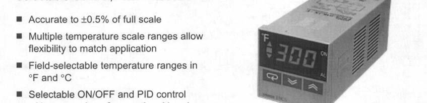
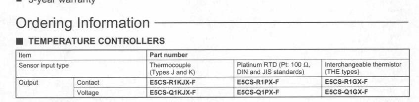
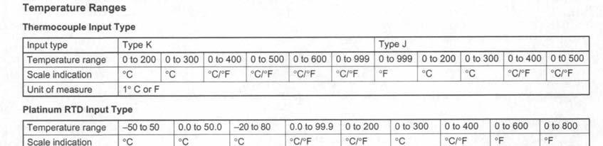
79 7.0 TROUBLESHOOTING 7.3 Temperature Controller Data Sheet OMRON E5CS-X Doc. P/N Rev


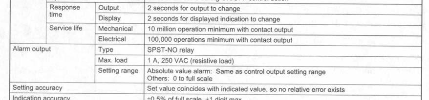
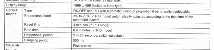

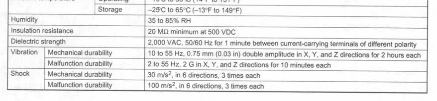
80 TROUBLESHOOTING 7.3 Temperature Controller Data Sheet OMRON E5CS-X (cont.) Doc. P/N Rev. 4.0

 Doc.")
81 7.0 TROUBLESHOOTING 7.3 Temperature Controller Data Sheet OMRON E5CS-X (cont.) Doc. P/N Rev. 4.0

 Doc.")
82 7.0 TROUBLESHOOTING 7.3 Temperature Controller Data Sheet OMRON E5CS-X (cont.) Doc. P/N Rev. 4.0
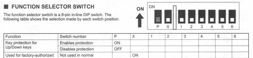
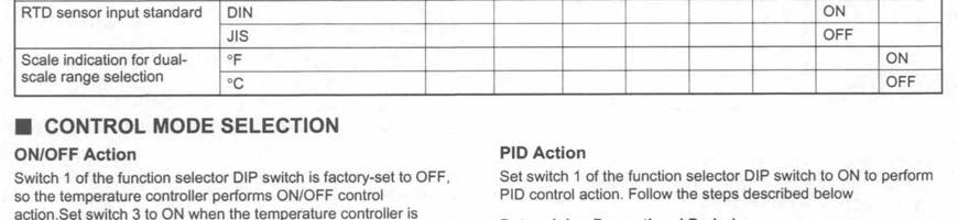
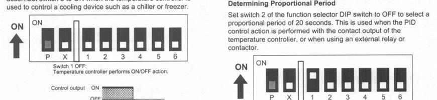
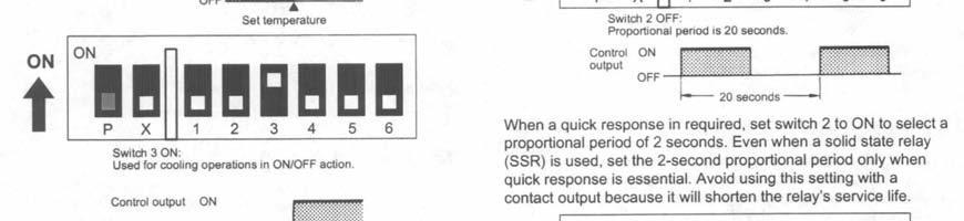
83 7.0 TROUBLESHOOTING 7.3 Temperature Controller Data Sheet OMRON E5CS-X (cont.) Doc. P/N Rev. 4.0
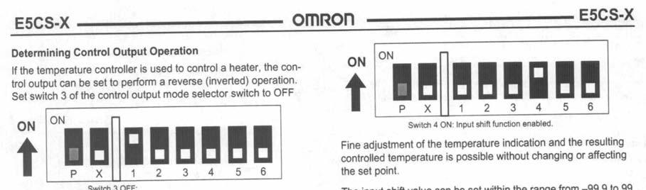
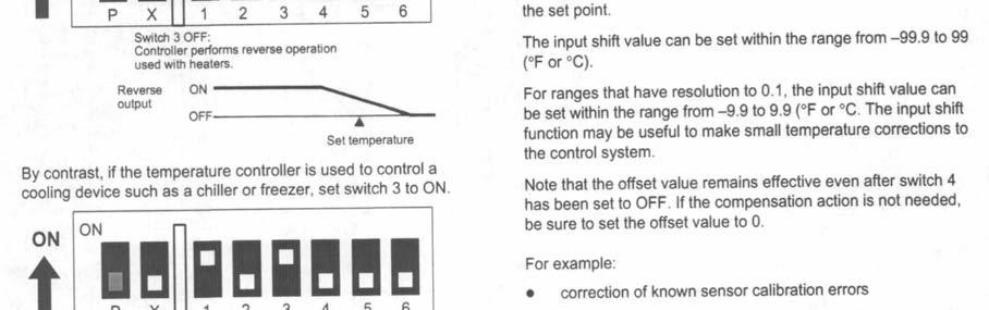
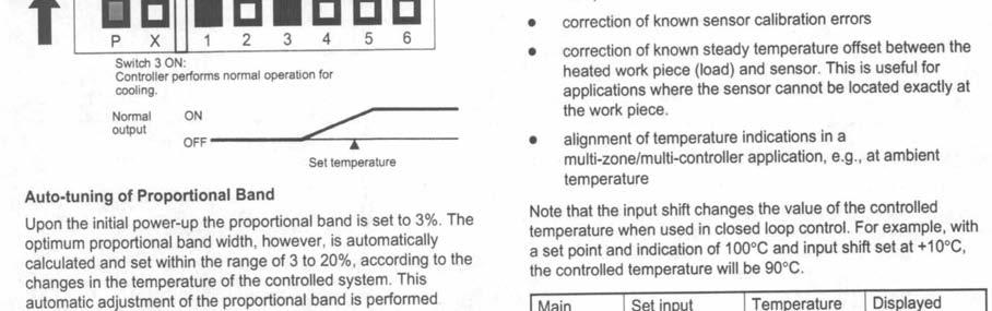
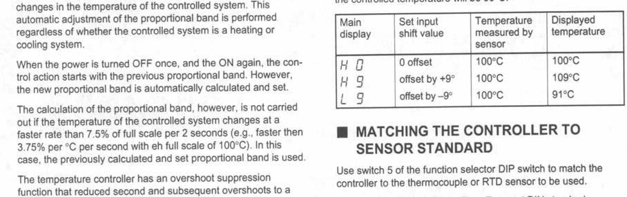
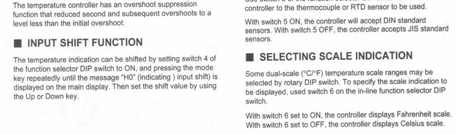
84 7.0 TROUBLESHOOTING 7.3 Temperature Controller Data Sheet OMRON E5CS-X (cont.) Doc. P/N Rev. 4.0

 Doc.")
85 7.0 TROUBLESHOOTING 7.3 Temperature Controller Data Sheet OMRON E5CS-X (cont.) Doc. P/N Rev. 4.0


86 7.0 TROUBLESHOOTING 7.3 Temperature Controller Data Sheet OMRON E5CS-X (cont.) Doc. P/N Rev. 4.0


87 7.0 TROUBLESHOOTING 7.3 Temperature Controller Data Sheet OMRON E5CS-X (cont.) Doc. P/N Rev. 4.0

 Doc.")
88 7.0 TROUBLESHOOTING 7.3 Temperature Controller Data Sheet OMRON E5CS-X (cont.) Doc. P/N Rev. 4.0
Atlas Model BCX Basic Cyclic Corrosion Cabinet
 Atlas Model BCX Basic Cyclic Corrosion Cabinet INSTRUCTION MANUAL Doc. P/N 17163600 Rev. 5.0 Atlas Material Testing Technology LLC 4114 North Ravenswood Avenue Chicago, IL 60613 USA Phone: (773) 327-4520
Auto Technology Company Cyclic Corrosion Test Chamber
 Auto Technology Company Cyclic Corrosion Test Chamber Built for Versatile and Repeatable Testing The Auto Technology Cyclic Corrosion Test (CCT) Chamber creates a variety of environments in an exposure
FILTRATION SYSTEM MODEL: FILTER - 5 MULTI-SHIFTER, INC. P.O. BOX CHARLOTTE, N.C TEL#: FAX#:
 FILTRATION SYSTEM MODEL: FILTER - 5 MULTI-SHIFTER, INC. P.O. BOX 411047 CHARLOTTE, N.C. 28241-1047 TEL#: 1-704-588-9611 FAX#: 1-704-588-4730 CONTENTS 1. System Overview 2. Air and Electrical Requirements
General System Layout Sketch
 General System Layout Sketch EZ-37 Solar Panels PV panel Glycol Fill Valve Expansion Tank ` 1 Introduction This document describes how to install a Heliatos GH type solar water heating system. These systems
Standard and CELDEK Evaporative Cooler Modules Installation, Operation, and Maintenance Manual
 Standard and CELDEK Evaporative Cooler Modules Installation, Operation, and Maintenance Manual Standard Evaporative Cooler CELDEK Evaporative Cooler RECEIVING AND INSPECTION Upon receiving unit, check
Equipment Alert. P-Trap Must Be Installed to Exhaust or Warranty will be Voided. Refer to this Manual for installation Instructions
 Dry Assembled Elbows MUST Glue when Installed Exhaust Connection P-Trap Must Be Installed to Exhaust or Warranty will be Voided AA2360 Refer to this Manual for installation Instructions 2011 Midmark Corp.
Fountain Classic. Installation and Owner s Manual. Page 16
 Fountain Classic Installation and Owner s Manual Page 16 4120 NW 44th St Lincoln, NE 68524 USA Tel: 402.467.9300 Toll Free in the USA: 800.875.5915 Fax: 402.467.9393 www.purewaterinc.com Page 2 Fountain
Standard and CELDEK Evaporative Cooler Modules Installation, Operation, and Maintenance Manual
 Standard and CELDEK Evaporative Cooler Modules Installation, Operation, and Maintenance Manual Standard Evaporative Cooler CELDEK Evaporative Cooler RECEIVING AND INSPECTION Upon receiving unit, check
INSTALLATION INSTRUCTIONS UNDERCOUNTER DISHWASHERS
 INSTALLATION INSTRUCTIONS UNDERCOUNTER DISHWASHERS VIKING 111 Front Street Greenwood, Mississippi 38930 USA (662) 455-1200 IMPORTANT - PLEASE READ AND FOLLOW Before beginning - please read these instructions
CELDEK Evaporative Cooler Module Installation, Operation, and Maintenance Manual. CELDEK Evaporative Cooler
 CELDEK Evaporative Cooler Module Installation, Operation, and Maintenance Manual CELDEK Evaporative Cooler RECEIVING AND INSPECTION Upon receiving unit, check for any interior and exterior damage, and
INSTALLATION, OPERATING & MAINTENANCE INSTRUCTIONS FOR 350 SERIES CIRCULATION HEATERS
 INDEECO Circulation Heaters are designed to provide years of trouble free operation if properly installed and maintained. Please read and follow these instructions for installing and maintaining the heater.
CHILLER. Operator s & Installation Manual
 CHILLER MODELS: CH1001-A Operator s & Installation Manual Release Date: August 9, 2002 Publication Number: 620914301 Revision Date: May 6, 2010 Revision: E Visit the IMI Cornelius web site at www.cornelius.com
CAUTION UM120W (RIGHT TANK) FOR WATER BORNE PAINTS ONLY UM120W (RIGHT TANK) SECTION IS NOT DESIGNED FOR USE WITH SOLVENT BASED PAINT
 FOR WATER BORNE PAINTS ONLY UM120W (RIGHT TANK) SECTION IS NOT DESIGNED FOR USE WITH SOLVENT BASED PAINT") OPERATING MANUAL SOLVENT AND WATER BASE SPRAY GUN CLEANER UG5000W and UG5500W CAUTION UM120W (RIGHT TANK) FOR WATER BORNE PAINTS ONLY UM120W (RIGHT TANK) SECTION IS NOT DESIGNED FOR USE WITH SOLVENT BASED
OPERATING MANUAL SOLVENT AND WATER BASE SPRAY GUN CLEANER UG5000W and UG5500W CAUTION UM120W (RIGHT TANK) FOR WATER BORNE PAINTS ONLY UM120W (RIGHT TANK) SECTION IS NOT DESIGNED FOR USE WITH SOLVENT BASED
ph COOLING TOWER CONTROLLER
 LAKEWOOD INSTRUMENTS MODEL 350 ph COOLING TOWER CONTROLLER INSTRUCTION MANUAL SERIAL #: Lakewood Instruments 7838 North Faulkner Road, Milwaukee, WI 53224 USA Phone (800) 228-0839 Fax (414) 355-3508 http://www.lakewoodinstruments.com
Page 1 of 18. Part# /5/2013
 Part# 1002655-06 8/5/2013 This manual contains important information concerning the installation and operation of the gun washers listed above. Read manual thoroughly and keep for future reference INSTRUCTIONS
J120 STEAM BOOSTER INSTALLATION, OPERATION, AND SERVICE MANUAL J120 STEAM BOOSTER. J120 Steam Booster Manual D
 INSTALLATION, OPERATION, AND SERVICE MANUAL J120 STEAM BOOSTER J120 STEAM BOOSTER J120 Steam Booster Manual REVISION HISTORY Revision Letter Revision Date Made by Applicable ECNs Details A 10-27-04 CBW
PARTS MANUAL. American Dish Service ADS CONVEYOR DISHWASHER MODELS: ADC-44 L-R/R-L EFFECTIVE: SEPTEMBER 1, 2001
 EFFECTIVE: SEPTEMBER 1, 2001 ADS CONVEYOR DISHWASHER MODELS: ADC-44 L-R/R-L PARTS MANUAL 900 Blake Street Edwardsville, Kansas 66111 (913)422-3700 211-0044L-R / 212-0044R-L ADC-44 Conveyor Dishwasher 2
ALTAIR II CONVECTION STEAM COOKER PARTS AND SERVICE MANUAL
 ALTAIR II CONVECTION STEAM COOKER PARTS AND SERVICE MANUAL EFFECTIVE MAY, 0 Superseding All Previous Parts Lists. The Company reserves the right to make substitution in the event that items specified are
Table of Contents. FETCO, and Driven To Pioneer Innovation are trademarks or trade names of Food Equipment Technologies Company.
 www.fetco.com Hot Water Dispensers User s Guide Maritime Versions Rated IP44 Table of Contents Contact Information... 2 Specifications... 2 Dimensions... 3 Installation... 4 Operating Instructions...6
215 Gallon Waste Oil Tank With Bypass Regulator Installation Instructions
 215 Gallon Waste Oil Tank With Bypass Regulator Installation Instructions Lanair Products LLC 4109 Capital Circle Janesville, Wisconsin 53546 1-888-370-6531 www.lanair.com BEFORE YOU BEGIN INSTALLATION...
OPERATING AND MAINTENANCE MANUAL FOR ELECTRIC STAINLESS STEEL HEATER FOR DEIONIZED (DI) WATER ELECTRIC HEATER COMPANY BASE MODEL D
 WATER ELECTRIC HEATER COMPANY BASE MODEL D") OPERATING AND MAINTENANCE MANUAL FOR ELECTRIC STAINLESS STEEL HEATER FOR DEIONIZED (DI) WATER ELECTRIC HEATER COMPANY BASE MODEL D HUBBELL ELECTRIC HEATER COMPANY P.O. BOX 288 STRATFORD, CT 06615 PHONE:
OPERATING AND MAINTENANCE MANUAL FOR ELECTRIC STAINLESS STEEL HEATER FOR DEIONIZED (DI) WATER ELECTRIC HEATER COMPANY BASE MODEL D HUBBELL ELECTRIC HEATER COMPANY P.O. BOX 288 STRATFORD, CT 06615 PHONE:
DRAIN WATER TEMPERING INSTALL
 ! WARNING! CAUTION DRAIN WATER TEMPERING KIT - 0601-00-07-86 WARNING! This kit should be installed only by qualified service personnel to reduce the risk of electric shock, serious injury, or fire. A plumbing
SECTION COMPRESSED AIR SYSTEM. A. Pipe and pipe fittings, including valves, unions and couplings.
 SECTION 15481 COMPRESSED AIR SYSTEM PART 1 - GENERAL 1.1 SECTION INCLUDES A. Pipe and pipe fittings, including valves, unions and couplings. B. Air compressor. C. After cooler. D. Refrigerated air dryer.
an ISO 9001:2015 Registered Company
 an ISO 9001:2015 Registered Company Mark IV (672001-VHY) 18865 Goll St. San Antonio, TX 78266 Phone: 800-862-6658 Sales: sales@vintageair.com Tech Support: tech@vintageair.com www.vintageair.com 902001-VHY
Owner s Manual Therma-Stor II Heat Recovery System
 PO Box 8680 Madison, WI 53708 TS-138C Revised 8/08 Owner s Manual Therma-Stor II Heat Recovery System Installation, Operation & Service Instructions Read and Save These Instructions Table Of Contents 1.
WATT R TWIN Energy-Efficient Home Water System
 WATT R TWIN Energy-Efficient Home Water System Owner and Installation Manual 3725 Touzalin Avenue Lincoln, NE 68507 USA Tel: 402.467.9300 Toll Free in the USA: 800.875.5915 Fax: 402.467.9393 www.purewaterinc.com
Pure Water C-630 Commercial Distillation System
 Pure Water C-630 Commercial Distillation System OWNERS MANUAL Published by: The Commercial Products Division Pure Water 4120 NW 44th Lincoln, Nebraska 68524 U.S.A. Telephone (402) 467-9300 Fax (402) 467-9393
HOT WATER BOILER ( MBH)
") GAS-FIRED DIRECT VENT CONDENSING HOT WATER BOILER (25-200 MBH) Repair PARTS MANUAL P/N 24000523, Rev. C [09/08] TABLE OF CONTENTS I. Circulator Pumps (Optional)...2 II. Burner Assembly...3 III. Boiler
GAS-FIRED DIRECT VENT CONDENSING HOT WATER BOILER (25-200 MBH) Repair PARTS MANUAL P/N 24000523, Rev. C [09/08] TABLE OF CONTENTS I. Circulator Pumps (Optional)...2 II. Burner Assembly...3 III. Boiler
4-1 1 / 2 " Tees / 2 " hole saw w/ 1/4" drill bit / 2 " Male slip plugs
 Section 1: Parts List 1-50 Flex PVC pipe 2-1 1 / 2 " Ball Valves 4-1/2" 90 degree elbows 4 - Lengths of 1/2" PVC 4 - Jet bodies 4 - Jet nozzles 4 - Female slip/female slip unions 2 - Female slip/fpt union
Cascade Premier and Elite Premier Bathing Systems with Aqua-Aire Installation / Assembly Instructions
 Cascade Premier and Elite Premier Bathing Systems with Aqua-Aire Installation / Assembly Instructions Premier Elite Premier PENNER PATIENT CARE, INC Box 523 / 102 Grant St. Aurora, NE 68818 360745P Revision
OPERATING AND MAINTENANCE MANUAL FOR PLATE HEAT EXCHANGER INDIRECT FIRED WATER HEATER. Electric Heater Company Base Model "BWXP"
 OPERATING AND MAINTENANCE MANUAL FOR PLATE HEAT EXCHANGER INDIRECT FIRED WATER HEATER Electric Heater Company Base Model "BWXP" HUBBELL ELECTRIC HEATER COMPANY P.O. BOX 288 STRATFORD, CT 06615 PHONE: (203)
Wilbur Curtis Company, Inc.
 Find out more on the web. WILBURCURTIS.COM MODEL WB-14-11 Service Manual Water Boiler 14 Gallon Gas Important Safeguards/Conventions This appliance is designed for commercial use. Any servicing other than
CATALOG OF REPLACEMENT PARTS
 CATALOG OF REPLACEMENT PARTS HPR SERIES PROOFER/RETARDER MODEL HPR1 ML-132406 30 In. (Standard) ML-132407 50 In. (Standard) ML-132408 63 In. (Standard) ML-132409 83 In. (Standard) ML-132410 96 In. (Standard)
Installation Instructions
 Installation Instructions For Free Standing NoFrost Combined Refrigerator-Freezers CS 1660 7084 203-00 Important Please Read and Follow these Instructions These instructions contain Danger, Warning and
WM-450-PT WM-900-PT Commercial Wall Mounted Reverse Osmosis
 WM-450-PT WM-900-PT Commercial Wall Mounted Reverse Osmosis Installation And Service Manual Watts Pure Water 1725 W. Williams Dr. C-20., Phoenix, Arizona 85027 Phone: 888-774-7405 Fax: 602-588-0356 www.wattspurewater.com
PURGER INSTALLATION AND OPERATION BULLETIN PUR-SB17-02 SERVICE BULLETIN
 VALVES VESSELS SYSTEMS CONTROLS PURGER INSTALLATION AND OPERATION BULLETIN PUR-SB17-02 SERVICE BULLETIN System drawings shown in this bulletin are for illustration purposes only. Refrigeration systems
Series 1140 and 1141 Temperature Regulators
 Hoffman Specialty Installation & Maintenance Instructions HS-504(E) Series 1140 and 1141 Temperature Regulators! CAUTION FOLLOW ALL INSTALLATION AND OPERATING INSTRUCTIONS. TURN OFF WATER OR STEAM BEFORE
OPERATING AND MAINTENANCE MANUAL FOR PACKAGED ELECTRIC TEPID WATER HEATING SYSTEMS BASE MODEL ESS
 OPERATING AND MAINTENANCE MANUAL FOR PACKAGED ELECTRIC TEPID WATER HEATING SYSTEMS BASE MODEL ESS THERM-OMEGA-TECH, INC. 353 IVYLAND RD, WARMINSTER, PA 18974 PHONE: (877) 379-8258 INTERNET: http://www.thermomegatech.com
PRE-ASSEMBLED RADIANT CONTROL PANEL INSTALLATION MANUAL
 FloorHeat PRE-ASSEMBLED RADIANT CONTROL PANEL INSTALLATION MANUAL Thank you for purchasing this radiant control panel assembly. Following are some important notes that will make the installation successful.
Cool IR. Model C104 - Cooling System. Instruction Manual
 Cool IR Model C104 - Cooling System Instruction Manual February 26, 2015 Research, Inc. USA Ph: 952.949-9009 Fax: 952.949-9559 tsdsales@researchinc.com www.researchinc.com Table of Contents List of Figures...
MODEL CMA-180UC SERVICE & PARTS MANUAL Rev 1.10
 MODEL CMA-180UC SERVICE & PARTS MANUAL Rev 1.10 CMA DISHMACHINES 12700 KNOTT AVENUE GARDEN GROVE, CALIFORNIA 92841 800-854-6417 FAX 714-895-2141 www.cmadishmachines.com 0203 TABLE OF CONTENTS MODEL CMA-180UC
WARNING DESCRIPTION PART NUMBER QTY PLUMBING, DYNATEMP DRAIN QUENCH BRACKET, THERMOSTAT DRAIN QUENCH
 ! WARNING WARNING: This kit should be installed only by qualified service personnel to reduce the risk of electric shock, serious injury, or fire. A plumbing permit and the services of a licensed plumber
Internet Version for Reference Only INDUCED DRAFT COMMERCIAL WATER HEATERS SUPPLEMENT INSTRUCTIONS TO PART #
 INDUCED DRAFT COMMERCIAL WATER HEATERS SUPPLEMENT INSTRUCTIONS TO PART #238-39387-00 THIS INSTRUCTION SUPPLEMENT IS ONLY INTENDED TO GIVE INSTALLATION INSTRUCTIONS AND INFORMATION RELATED TO THE INDUCED
Getz Equipment Innovators 450 lb Dual Portable Dry Chemical Fill System
 Getz Equipment Innovators 450 lb Dual Portable Dry Chemical Fill System 1 Revised 11/18/10 2320 Lakecrest Drive, Pekin IL 61554 PH. (888) 747-4389 Fax (309) 495-0625 Website: www.getzequipment.com LIMITED
INSTALLATION, OPERATION AND MAINTENANCE MANUAL FOR COMMERCIAL INDIRECT POWERED WATER HEATER
 INSTALLATION, OPERATION AND MAINTENANCE MANUAL FOR COMMERCIAL INDIRECT POWERED WATER HEATER ELECTRIC HEATER COMPANY BASE MODEL T Edition 0 HUBBELL ELECTRIC HEATER COMPANY P.O. BOX 88 STRATFORD, CT 0665
MIX Boiler & Font Range Service Manual
 MIX Boiler & Font Range Service Manual 1000870# 1000871# 1000875# 1000880# 1000887# 1000878 1000879 2300268 www.marcobeveragesystems.com Ireland Tel: +353 (1) 295 2674 UK Tel: +44 (0207) 2744577 Service
Table of Contents 1. OVERVIEW SYSTEM LAYOUT SPECIFICATIONS FUNCTION... 11
 Table of Contents 1. OVERVIEW... 3 2. SYSTEM LAYOUT... 4 3. SPECIFICATIONS... 8 3.1 SYSTEM COMPONENTS...9 3.2 PLC INPUTS AND OUTPUTS...9 3.3 FUNCTION KEYS...10 3.4 DEFAULT SET POINTS AND TIMERS...10 4.
WARNING. Failure to install this kit within the guidelines might adversely affect safety, performance, component life and warranty coverage.
 ! WARNING WARNING: This kit should be installed only by qualified service personnel to reduce the risk of electric shock, serious injury, or fire. A plumbing permit and the services of a licensed plumber
MODEL CMA-180UC PARTS MANUAL Rev 1.16
 MODEL CMA-180UC PARTS MANUAL Rev 1.16 CMA DISHMACHINES 12700 KNOTT STREET GARDEN GROVE, CALIFORNIA 92841 800-854-6417 FAX 714-895-2141 wwwcmadishmachines.com TABLE OF CONTENTS MODEL CMA-180UC 1. PARTS
B-14G. for series number with jm or j
 B-G boilerless steamer REPLACEMENT PARTS LIST for series number with jm or j Effective june, 0 Superseding All Previous Parts Lists. The Company reserves the right to make substitution in the event that
PARTS MANUAL. American Dish Service. ADS HIGH TEMP SINGLE RACK DISHMACHINE MODELS: HT-25 5 WIRE 110 Volt Control System
 EFFECTIVE: MAY 1, 2018 ADS HIGH TEMP SINGLE RACK DISHMACHINE MODELS: 5 WIRE 110 Volt Control System PARTS MANUAL 900 Blake Street Edwardsville, Kansas 66111 (913)-422-3700 C 05/2018 The American Dish Service
HOMEADVANTAGE II IMPORTANT SAFETY INFORMATION
 INSTALLATION INSTRUCTIONS & HOME OWNERS MANUAL HOMEADVANTAGE II HA008240 HA011240 HA013240 HA018240 HA024240 HA027240 HA036240 IMPORTANT SAFETY INFORMATION When installing or using any high voltage electrical
INSTALLATION INSTRUCTIONS FOR MULTI-UNIT RESIDENTIAL APPLICATIONS INSTALLATION INSTRUCTIONS ARE PER UNIT MODELS: RS-502C, RS-503C, RS-702C, RS-703C
 ROMA STEAM BATH 16802 BARKER SPRINGS DRIVE HOUSTON, TEXAS 77084 (281) 578-9945 1-800-657-0656 RES-M-RS INSTALLATION INSTRUCTIONS FOR MULTI-UNIT RESIDENTIAL APPLICATIONS INSTALLATION INSTRUCTIONS ARE PER
ORP/MILLIVOLT CONTROLLER
 LAKEWOOD INSTRUMENTS MODEL 330 ORP/MILLIVOLT CONTROLLER INSTALLATION & OPERATION MANUAL SERIAL #: Lakewood Instruments 7838 North Faulkner Road, Milwaukee, Wisconsin 53224 USA Phone (800) 228-0839 Fax
MODEL CMA-180UC PARTS MANUAL Rev 1.18
 MODEL CMA-180UC PARTS MANUAL Rev 1.18 CMA DISHMACHINES 12700 KNOTT AVENUE GARDEN GROVE, CALIFORNIA 92841 800-854-6417 FAX 714-895-2141 wwwcmadishmachines.com TABLE OF CONTENTS MODEL CMA-180UC 1. PARTS
1-866-PENNERS
 Cascade Premier and Elite Premier Bathing Systems with Aqua-Aire Installation / Assembly Instructions Premier Elite Premier PENNER PATIENT CARE, INC Box 523 / 102 Grant St. Aurora, NE 68818 360745P Revision
BCX-14 & BX-14 COMBINATION OVEN STEAMER CNVX-14 CONVECTION OVEN REPLACEMENT PARTS LIST
 BCX- & BX- COMBINATION OVEN STEAMER CNVX- CONVECTION OVEN REPLACEMENT PARTS LIST EFFECTIVE APRIL, 0 Superseding All Previous Parts Lists. The Company reserves the right to make substitution in the event
Harvey Chemiclave EC Series Sterilizers
 BARNSTEAD THERMOLYNE CORPORATION CHEMICLAVE EC SERIES STERILIZERS Harvey Chemiclave EC Series Sterilizers PARTS CATALOG LT1121x 12/10/98 1 Final Assembly - Refer to Figure 1 Figure Page 1 Final Assembly
MDH Series Air Dryer. User s Guide
 MDH Series Air Dryer User s Guide Models covered: MDH1 MDH2 MDH3 MDH4 MDH5 MDH6 1. Welcome & Congratulations Congratulations on your purchase of a new PUREGAS MDH SERIES AIR DRYER! We here at PUREGAS
ECOJET EJ-10E & EJ-7E ELECTRIC CONVECTION STEAMER W/TWIN GENERATORS PARTS AND SERVICE MANUAL
 ECOJET EJ-10E & EJ-7E ELECTRIC CONVECTION STEAMER W/TWIN GENERATORS PARTS AND SERVICE MANUAL EFFECTIVE JULY 31, 2014 Superseding All Previous Parts Lists. The Company reserves the right to make substitution
CHLORIDE GASES CHLORIDES
 Note: Always have this machine s model and serial number (printed on the first page of this document) ready when calling Consolidated for service or parts. WARNING If this sterilizer s chamber is constructed
MODELS CMA-180 VL/180 VLTall PARTS MANUAL Rev 2.02A
 MODELS CMA-180 VL/180 VLTall PARTS MANUAL Rev 2.02A C M A D I S H M A C H I N E S 1 2 7 0 0 K N O T T A V E N U E GARDEN GROVE, CALIFORNIA 92841 800-8 5 4-6 4 1 7 FAX 714-895-2141 www.cmadishmachines.com
L A signature series TA T N E RE O, A L L A T S IN
 signature series COMMERCIAL STEAM GENERATORS INSTALLATION, OPERATION AND MAINTENANCE MANUAL INSTALLATION MANUAL COMMERCIAL STEAM GENERATOR SIGNATURE SERIES (SS) INTRODUCTION Steam Sauna manufactures steam
CHILLER. Model CH3000. Operator s & Installation Manual
 CHILLER Model CH3000 Operator s & Installation Manual Release Date: February 14, 2011 Publication Number: 620054173OPR Revision Date: May 08, 2014 Revision: B Visit the Cornelius web site at www.cornelius.com
ACT Cartridge Dust Collector
 IOM-101-1 ACT Cartridge Dust Collector Installation and Operation Manual ACT Dust Collectors CAUTION! Accidents happen, be careful and always follow all local and federal regulations! Fires and explosions
Water Boilers ME10EN, ME15EN. Table of Contents
 Water Boilers ME10EN, ME15EN Operator Manual Model ME15EN Model ME10EN Safety Information...2 Rough-In Drawing...3 Installation...4 Priming...5 Cleaning...5 Table of Contents Adjustments...6 Maintenance...7
OPERATING MANUAL. Reverse Osmosis Equipment Model: Frame Mount Vertical FMV-1 through FMV-6. Made in U.S.A.
 OPERATING MANUAL Reverse Osmosis Equipment Model: Frame Mount Vertical FMV-1 through FMV-6 Made in U.S.A. TABLE OF CONTENTS Model: Frame Mount Vertical COMPONENT IDENTIFICATION Page 1 IMAGE OF R. O. SYSTEM
ES Series Electric Humidifier
 Read and Save These Instructions Standard Water ES Series Electric Humidifier Installation Instructions Operation and Maintenance Manual ETL LISTED HUMIDIFIER Our results are comforting Form No: ESOM-08-08
PARTS MANUAL. American Dish Service ADS HIGH TEMP SINGLE RACK DISHMACHINE MODEL: HT Blake Street Edwardsville, Kansas (913)
") EFFECTIVE: MAY, 2014 ADS HIGH TEMP SINGLE RACK DISHMACHINE MODEL: PARTS MANUAL 900 Blake Street Edwardsville, Kansas 66111 (913)-422-3700 05/08 The American Dish Service part numbers contained in this
EFFECTIVE: MAY, 2014 ADS HIGH TEMP SINGLE RACK DISHMACHINE MODEL: PARTS MANUAL 900 Blake Street Edwardsville, Kansas 66111 (913)-422-3700 05/08 The American Dish Service part numbers contained in this
GLC/GW-100 MANUAL INSTALLATION SERVICE PARTS REV.1.01
 Owner s Manual Keep with machine for reference GLC/GW-100 MANUAL INSTALLATION SERVICE PARTS REV.1.01 CMA DISHMACHINES 12700 KNOTT STREET GARDEN GROVE, CALIFORNIA 92841 800-854- 6417 FAX 714-895- 2141 www.cmadishmachines.com
"ESDDR" Series Electric Humidifier
 ESDDR-1 Deionized, Demineralized, or Reverse Osmosis Water "ESDDR" Series Electric Humidifier The Electric Humidifier from PURE Humidifier Co. is loaded with features and options. All you need is deionized,
Easy Dose Chemical Injection and Dispensing System DEMA Engineering Company
 Easy Dose Chemical Injection and Dispensing System DEMA Engineering Company Overview The DEMA Easy Dose is a simple and reliable chemical delivery system. Easy Dose features an electronic control system
The Danger signal indicates an immediately hazardous situation which, if not avoided, will result in death or serious injury.
 The Danger signal indicates an immediately hazardous situation which, if not avoided, will result in death or serious injury. The Warning signal alerts you to potential hazards or unsafe practices which,
CH250 AND CH251 CHILLERS
 CH250 AND CH251 CHILLERS Operator s & Installation Manual Release Date: April 19, 2004 Publication Number: 620914801 Revision Date: May 15, 2015 Revision: G Visit the Cornelius web site at www.cornelius.com
INSTALLATION AND OPERATION MANUAL STEAM COIL BASE CONVECTION STEAMER MODEL SCX-16
 INSTALLATION AND OPERATION MANUAL STEAM COIL BASE CONVECTION STEAMER MODEL SCX-16 CROWN FOOD SERVICE EQUIPMENT LTD. 70 OAKDALE ROAD, DOWNSVIEW, (TORONTO), ONTARIO, CANADA, M3N 1V9 TELEPHONE: (416) 746-2358,
A HEATER KIT With Diesel Engine Connection Fittings
 A-12142 HEATER KIT With Diesel Engine Connection Fittings Figure 1 (General Layout and Parts I.D.) Page 1 of 6 Read these instructions and identify all components. Please retain these instructions for
5700-E Sediment Filter Installation & Start-Up Guide
 Clean Water Made Easy www.cleanwaterstore.com 5700-E Sediment Filter Installation & Start-Up Guide Thank you for purchasing a Clean Water System! With proper installation and a little routine maintenance
Series 300 VTB. Installation Instructions
 Series 300 VTB Installation Instructions Sizes 7 12 16 20 30 HP #2 Fuel Oil Gas (500 to 2500 BTU) Gas Light Oil Combination High Pressure Steam Sizes 7 thru 16 HP (125 PSI) Sizes 20 and 30 HP (150 PSI)
Dual Column Dehydrating Breather Manual
 Dual Column Dehydrating Breather Manual DCB-MANUAL 1.6 Read and understand this manual prior to operating or servicing the products. SPX Transformer Solutions, Inc., Service & Components Division U.S.
FCT-CE SERIES ELECTRIC TILTING KETTLE W/HAND CRANK PARTS AND SERVICE MANUAL
 FCT-CE SERIES ELECTRIC TILTING KETTLE W/HAND CRANK PARTS AND SERVICE MANUAL EFFECTIVE SEPTEMBER 12, 2014 Superseding All Previous Parts Lists. The Company reserves the right to make substitution in the
CHILLERS. Operator s & Installation Manual
 CHILLERS MODELS: CH750, CH751 & CH951 Operator s & Installation Manual Release Date: April 19, 2002 Publication Number: 91256 Revision Date: May 5, 2010 Revision: D Visit the IMI Cornelius web site at
Salt Spray Cabinet. Manual. Model Ref.: VF7705 (500 liter) VF7710 (1000 liter)
 VF7710 (1000 liter)") Salt Spray Cabinet Manual Model Ref.: VF7705 (500 liter) VF7710 (1000 liter) Health & Safety The Manufacturer is required to ensure, for reasons of Health and Safety at Work that, as far as is reasonably
Salt Spray Cabinet Manual Model Ref.: VF7705 (500 liter) VF7710 (1000 liter) Health & Safety The Manufacturer is required to ensure, for reasons of Health and Safety at Work that, as far as is reasonably
USER MANUAL SPRAY GUN CLEANER - WATER BASED PAINTS UA400W CAUTION FOR WATER BORNE PAINTS ONLY
 USER MANUAL SPRAY GUN CLEANER - WATER BASED PAINTS UA400W CAUTION FOR WATER BORNE PAINTS ONLY THIS UNIT IS NOT DESIGNED FOR USE WITH SOLVENT BASED PAINT UNI-RAM CORPORATION ONTARIO CANADA REV 2010-09 CONTENTS
AQUAS POOL PACKAGE INSTALLATION INSTRUCTIONS FOR MODELS: AP AQUAS Pool Package
 100285340_2000542910_Rev A AQUAS POOL PACKAGE INSTALLATION INSTRUCTIONS FOR MODELS: AP 400-850 AQUAS Pool Package The AQUAS pool package system is a high efficiency commercial condensing boiler, pre-piped
LABORATORY AIR COMPRESSORS AND VACUUM PUMPING SYSTEMS
 SECTION 22 20 00 LABORATORY AIR COMPRESSORS AND VACUUM PUMPING SYSTEMS PART 1 - GENERAL 1.1 RELATED DOCUMENTS: A. The Conditions of the Contract and applicable requirements of Division 1, "General Requirements",
DRY AIR SYSTEMS, INC Metro Boulevard Maryland Heights, Missouri (314) fax (314)
 fax (314)") DRY AIR SYSTEMS, INC. 2655 Metro Boulevard Maryland Heights, Missouri 63043 (314) 344-1114 fax (314) 344-0677 HD SERIES DRIERS TABLE OF CONTENTS WHY AN AIR DRYER 3 WHAT IS A DESICCANT AIR DRYER 3 Desiccant
DRY AIR SYSTEMS, INC. 2655 Metro Boulevard Maryland Heights, Missouri 63043 (314) 344-1114 fax (314) 344-0677 HD SERIES DRIERS TABLE OF CONTENTS WHY AN AIR DRYER 3 WHAT IS A DESICCANT AIR DRYER 3 Desiccant
Columbia Boiler Company
 EMG Series Boilers Available in Natural Gas & Propane Rev 12012 Columbia Boiler Company PO Box 1070 Pottstown, PA 19464 Tel (610) 473-8457 Fax (610) 367-6800 Website www.columbiaboiler.com Email cbcsales@ptd.net
Powers Controls Free Energy Band TH 193 HC Hesitation Room Thermostat
 Document No. 155-069P25 TH 193-5 Powers Controls Free Energy Band TH 193 HC Hesitation Room Thermostat 50 60 70 80 TH0356R1 70 60 80 POWERS Description Features The TH 193 HC Hesitation Thermostats are
MODELS CMA-180 VL/180 VLTall PARTS MANUAL Rev 2.02B
 MODELS CMA-180 VL/180 VLTall PARTS MANUAL Rev 2.02B C M A D I S H M A C H I N E S 1 2 7 0 0 K N O T T A V E N U E GARDEN GROVE, CALIFORNIA 92841 800-8 5 4-6 4 1 7 FAX 714-895-2141 www.cmadishmachines.com
V SERIES HDR GAS RANGES
 SERVICE MANUAL ONE POWERFUL PACKAGE V SERIES HDR GAS RANGES TOPS Open Top Hot Top Griddle Top Work Surface BASES Standard Oven Convection Oven Cabinet Base - NOTICE - This manual is prepared for use by
Owner s Manual. Keep with machine for reference PKC24 INSTALLATION & OPERATION REV Perlick Corporation 8300 W Good Hope Rd Milwaukee, WI 53223
 Owner s Manual Keep with machine for reference PKC24 INSTALLATION & OPERATION REV.11.09 Perlick Corporation 8300 W Good Hope Rd Milwaukee, WI 53223 800-558- 5592 FAX 414-353- 7069 perlick.com TABLE OF
WATLOW IND. WATROD Modular Duct Heater Installation & Maintenance Manual I&M NUMBER: Page: 1 Date:6/11/2008 Rev: 2
 I&M NUMBER: 316-42-15-1 Page: 1 _ Pre Installation Check to make sure that heater received is the same as that ordered. Elements may come in contact with each other during shipment. Minor adjustments to
Mix Boiler & Font Range ( #, #, #, , )
") Mix Boiler & Font Range (1000870#, 1000871#, 1000880#, 1000878, 1000879) Service Manual Marco Beverage Systems Ltd. 63d Heather Road, Sandyford Industrial Estate, Dublin 18, Republic of Ireland Ireland
Mix Boiler & Font Range (1000870#, 1000871#, 1000880#, 1000878, 1000879) Service Manual Marco Beverage Systems Ltd. 63d Heather Road, Sandyford Industrial Estate, Dublin 18, Republic of Ireland Ireland
EBAC MODEL WM150 INDUSTRIAL DEHUMIDIFIER OWNER S MANUAL
 EBAC MODEL WM150 INDUSTRIAL DEHUMIDIFIER OWNER S MANUAL WM150 OWNERS MANUAL Page 1 of 9 INTRODUCTION Designed for a wide range of applications, the WM150 is a rugged, industrial unit, which utilizes an
OPERATING MANUAL SOLVENT SPRAY GUN CLEANERS UG5000E, UG5000DVM AND UG5500E UNI-RAM CORPORATION ONTARIO CANADA PATENTS
 OPERATING MANUAL SOLVENT SPRAY GUN CLEANERS UG5000E, UG5000DVM AND UG5500E PATENTS USA 4,788,836 CANADA USA 5,213,117 ENGLAND EUROPE 0300248 ITALY SWEDEN 0300248 GERMANY FRANCE 8110528.0 JAPAN UNI-RAM
Models: GW/R-T GW/R-2-T GW/R-3-T
 Part# GW/R-T-OM 1/12/04 TN Models: GW/R-T GW/R-2-T GW/R-3-T This manual contains important information concerning the installation and operation of the gun washers listed above. Read manual thoroughly
OPERATING & SERVICE PARTS MANUAL HDS-215 COMBINATION SHRINK SYSTEM
 OPERATING & SERVICE PARTS MANUAL HDS-215 COMBINATION SHRINK SYSTEM FOR HOT KNIFE AND IMPULSE MACHINES READ ALL INSTRUCTIONS CAREFULLY BEFORE OPERATING EQUIPMENT TABLE OF CONTENTS Electrical Requirements
Weil-McLain part numbers are found in Weil-McLain Boilers and Controls Repair Parts Lists.
 gas-fired water boiler Manual Replacement parts Replacement parts must be purchased through a local Weil-McLain distributor. When ordering, specify boiler model and size and include description and part
Niles Steel Tank Hot Water Generator Installation and Operation Manual
 Niles Steel Tank Hot Water Generator Installation and Operation Manual Contents: Contents 1 Hazard definitions 1 1. General Information.... 2 Availability... 3 Optional Control Packages... 5 2. Installation....
Installation & Operating Guide
 5-036 HOT WATER TANK Installation & Operating Guide Read all instructions thoroughly. Keep this guide for future reference. Proof of purchase is required for Warranty. Staple receipt or proof of purchase