Mounting instructions Genius Radio
|
|
|
- Hugo Hicks
- 5 years ago
- Views:
Transcription


1 Mounting instructions Genius Radio anleitung Genius Funk TON en.indd
2 Inhalt 1. General information Safety Design of radio modules Product presentation Signal transfer times Quick guide Line setting Mounting of Basis/Pro radio module Range test Commissioning of Basis/Pro radio modules Maintenance of Basis/Pro radio modules Settings Pro radio module Collective alarms Dismounting detector/transmission path monitoring Removal of a radio module Delete identification code/factory setting Extend radio network Acknowledge status message Montageanleitung Genius Funk TON en.indd :53
3 19. Acknowledge fire alarm Acknowledge dismounting detection and transmission path monitoring Operating and warning signals Disposal Guarantee and warranty Guarantee handling Technical data Ordering data General information The Hekatron Basis and Pro radio modules were specially developed for application in the smoke detector Genius Hx. In combination with the Basis and Pro radio modules, the smoke detector Genius Hx is recognised according to VdS 3515 as a smoke detector with connection to radio networks VdS G no The smoke detectors connected to the Basis and Pro radio modules are not a replacement for a central fire alarm system. If, in case of smoke or a detected fire, an alarm transfer to the fire brigade is desired or required, control and indicating equipment according to DIN must be used. We can support you in your planning and designing of the central fire alarm system. Hekatron does not accept any liability for expenditures of time, material and money which may result from alarming a manned station, e.g. security firm or fire brigade. Please read these mounting and operating instructions before mounting the radio module and keep these instructions for future reference. Your specialist dealer will be pleased to help you in case of any question. For mounting and operation of the smoke detector Genius Hx, please read the mounting instructions Genius Hx Part no Montageanleitung Genius Funk TON en.indd :53
4 2. Safety 2.1. Explanation of symbols Safety notes and warnings are marked by symbols in these mounting and operating instructions. These notes are introduced by signal words which express the extent of the risk. Always take the notes into account in order to avoid personal injury and property damage. Safety notes and warnings: WARNING!... indicates a possibly hazardous situation which may lead to death or severe injury if it is not avoided. CAUTION!... indicates a possibly hazardous situation which may lead to property damage if it is not avoided. NOTE!... highlights useful tips and recommendations as well as information for an efficient and trouble-free operation Intended use The Basis and Pro radio modules may only be installed in the smoke detectors Genius Hx. The field of application is restricted to residential houses, apartments and rooms with similar purposes. Radio linked smoke detectors do not constitute a replacement for a central fire alarm system. WARNING! Danger due to improper use! Each use exceeding the intended use and/or any other use of the Basis and Pro radio modules may lead to hazardous situations. Therefore: Only use the Basis and Pro radio modules in accordance with their intended purpose. Any and all information of the mounting and operating instructions must be strictly observed. Claims of any kind due to damages resulting from improper use are excluded. 6 7 Montageanleitung Genius Funk TON en.indd :53
5 2.3. Safety notes WARNING! Improper mounting, start-up and maintenance of the Basis and Pro radio modules may lead to gaps in fire protection and to dangerous situations. Therefore: The mounting and operating instructions for the Basis and Pro radio modules must be read and understood before the work is started. All safety notes must be observed and all guidelines must be complied with. The mounting, start-up and maintenance of the smoke detectors with radio module should be carried out by a trained specialist. If the smoke detectors with radio module are removed during renovation works, there is no fire protection during this period. Therefore: Smoke detectors with radio module must be mounted and commissioned after the work has been completed. No more than 20 radio modules must be set to the same line and to the same ID. Claims of any kind due to damages resulting from non-observance are excluded. For safety notes relating to the smoke detector, please refer to the mounting instructions Genius Hx. 8 9 Montageanleitung Genius Funk TON en.indd :53
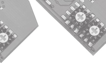
6 I H I H Design of radio modules 4. Product presentation 4.1. Properties of the Basis and Pro radio modules Basis radio J G 9 6 A F 0 5 B C E 1 4 D Pro radio on J G 9 6 A F 0 5 B C E 1 4 D Line formation via rotary switch: Two rotary switches for setting a maximum of 70 lines (see chapter 6). All radio smoke detectors of the same line can exchange messages. At least two radio smoke detectors must be installed per line. Rotary switch for setting the line (A-I and 0-9) DIP switch / function switch for Pro radio module Guide openings Signal LED Operating button Identification code Each line automatically receives a clear identification code (ID) upon commissioning which is used by all detectors of this line. After commissioning, the radio modules can only be actuated by messages from radio modules of the same line and ID. Messages from neighbouring systems are ignored Scope of delivery 1 x Basis or Pro radio module 1 x mounting and operating instructions Line A.1 + ID e.g No radio connection due to different ID Line A.1 + ID e.g Line A.1 + ID e.g Line A.1 + ID e.g Line A.1 + ID e.g Line A.1 + ID e.g Line A.1 + ID e.g Line A.1 + ID e.g Montageanleitung Genius Funk TON en.indd :53
7 Simultaneous start-up of several radio networks: Radio networks of different line settings can be commissioned at the same time. Repeater function (amplifier): Each radio module has a repeater. Repeaters receive signals and forward them with the maximum transmission power. All messages with the same line and ID and messages which are intended for the radio module via a collective alarm line (see chapter 12) are forwarded. Messages which are not from the same line or which are not intended for the radio module are not repeated (amplified). Messages are not changed by the repeater. Alarm transmission: If a smoke detector with radio module detects a fire, a corresponding message is sent to the radio network via its radio module after approx. 20 seconds: To all radio modules in the same line and ID. To the corresponding collective alarm line. By pressing the test button on this smoke detector before these 20 seconds elapse, forwarding of the message is avoided. The connected smoke detectors remain in alarm status until they are acknowledged or until the sensing chamber of the triggering smoke detector is free of smoke. Range tests: Each radio module can be used for the range measurement. With the range measurement, the number (maximum of 9 pieces) of smoke detectors in a radio zone or the largest possible distance between two radio modules can be determined Montageanleitung Genius Funk TON en.indd :53
8 Fast alarm localisation: By pressing the test button of a smoke detector which signals a received alarm, all audible alarms will turn off, except the smoke detector which has detected smoke. Smoke detectors which have detected smoke keep signalling the alarm and can thereby be localised as fast as possible. Integrated real-time clock: By means of the integrated real-time clock in the Genius Hx, a status message which does not affect the operation of the smoke detector is suppressed between 10 pm and 6 am CET (winter time) Basis radio module The Basis radio module was designed for application in apartments, singlefamily homes or similar environments. For configuration of a Basis radio module, only the line must be set and start-up must be carried out. The functions of the Basis radio module are set at the factory (see table 4.3). The Pro radio module has additional functions available. NOTE! The Basis and Pro radio modules are compatible and can be combined in a radio network Montageanleitung Genius Funk TON en.indd :53
9 4.3. Pro radio modules In addition to the functions of the Basis radio module, the following functions can be switched on/off by the DIP switch on the Pro radio module: DIP switch Function 1 Suppress warnings (messages such as "Battery low" or failures of other smoke detectors are not signalled). 2 Alarm suppression (fire alarms from other smoke detectors are not signalled) Factory setting Pro/Basis Off*/ Off ** Off*/ Off ** 3 Send collective alarm Off*/ Off ** 4 Receive collective alarm Off*/ Off ** 5 Dismounting detector/ transmission path monitoring Off*/ Off ** 6 Reduction of transmitting power Off*/ Off ** * With the Pro radio module, these functions can be switched on or off. ** With the Basis radio module, these functions are set and cannot be switched on or off. Suppress alarms and warnings By means of the DIP switch on the Pro radio module, signalling of a received alarm or warning can be suppressed. An own alarm or warning cannot be switched off. Collective alarm lines Alarms and warnings can also be sent to other lines by means of collective alarm lines. So alarms and warnings can be sent e.g. from the stairwell to the apartment, from the apartment to the stairwell or in both directions. Collective alarm lines are created via the lines H.0 to H.2, H.4, H.5 and H.7 (see chapter 12.1). In a radio network* no more than 60 radio smoke detectors must be installed. In the case of larger objects, please contact our technical support. NOTE! In the case of larger radio networks, the signal transfer time may increase if several messages are circulating at the same time. Maximum signal transfer time** = Number of detectors x 3.5s Also see chapter 5 Signal transfer times. * Def. radio network: All radio smoke detectors which start an alarm if a fire is detected. ** If several messages are circulating, the signal transfer time is increased accordingly. With two messages, the signal transfer time doubles, with 3 messages it triples etc Montageanleitung Genius Funk TON en.indd :53
10 Dismounting detector The Pro radio module automatically detects a non-authorised removal of the smoke detector, e.g. due to theft. The connected radio smoke detectors signal this with an audible alarm. Transmission path monitoring The radio system automatically checks all radio modules of one line for availability. If a radio module cannot be found any more, the radio system signals this. 5. Signal transfer times In the project planning of a radio network, the spreading rate of a radio telegram has to be observed imperatively. If the radio network is in its idle state (no radio networks in circulation), the signal spreads very rapidly (approx seconds). If telegrams are in circulation, the emission of the telegram will be deferred according to the following formula: Maximum signal transfer time = number of detectors x 3.5s Example: There are 20 radio smoke detectors in a radio network. One of these detectors detects smoke and sends the alarm telegram to its connected detectors after 20 seconds have expired. If the alarm signal is acknowledged shortly after sending, it takes a maximum of 70 seconds (20 smoke detectors*3.5s) until all radio smoke detector turn off again. If the alarm is acknowledged after the signal transfer time has expired, all radio smoke detectors turn off after 5-10 seconds. t0=0s t2=22s t2=22s Fire Brand detection detektion Alarm quittiert t1=20s Alarm Alarm is wird sent versendet acknowledged t3=90s Alarm offaus Montageanleitung Genius Funk TON en.indd :53
11 6. Quick guide In order to set, mount and commission smoke detectors with radio module, at least the following steps have to be carried out. For supporting information please refer to the planning manual Genius H and Hx. 6.1 Project planning Before mounting the smoke detectors with radio module, the project planning according to DIN (also see mounting instructions Genius Hx ) has to be carried out. In this process: The number of smoke detectors with radio module, The mounting positions, The respective line, The settings on the DIP switch (only Pro radio modules) Should be determined. This information should be documented e.g. in the start-up and maintenance set (SM set Genius). NOTE! The distance between two radio smoke detectors should be at least 50 cm in order to ensure a safe radio connection. NOTE! A minimum distance of 2m should be maintained with regard to the following electric devices: Wifi, DECT, radio weather stations, radio speakers, babyphones, radio garage door openers 6.2. Line setting and mounting Step What needs to be done? 1 Mount the bases of the smoke detectors according to the project planning. Pay attention to the mounting directions in the mounting instructions Genius Hx. 2 Set rotary switch on the radio module according to the project planning. 3 Only Pro radio module: Set DIP switch according to project planning. 4 Insert radio module into the respective smoke detector (see chapter 7). 5 Screw the smoke detector into the base, please refer to the mounting instructions Genius Hx. 6 After the smoke detector was screwed into the base, the automatic self-test of the smoke detector, not of the radio module, is carried out. 7 Commissioning of the radio network (see chapter 9) Montageanleitung Genius Funk TON en.indd :53
12 I I I 7. Line setting By means of the rotary switch of the radio module, the line of the respective radio module can be set. All radio modules of the same line can exchange messages after commissioning. A line is composed of a letter (A to G) and a number (0 to 9). The collective alarm line is composed of the letter H and a number (0,1,2,4,5 and 7). The range test is composed of the lines I.0 and I.1. NOTE! Settings on the rotary switches for line formation must be made before the radio module is inserted into the smoke detector. The settings are read upon insertion and upon new commissioning. If the settings are changed after commissioning, the radio modules have to be commissioned again (see chapter 9). The lines H.3, H.6, H.8,H.9, I.2 to I.9 and J.0 to J.9 do not have any function. J A B C J A B C J A B C H D 7 H G F E D 7 H G F E D 7 G F E Line C.3 Line B.5 Line A.2 NOTE! The rotary switches should be set by means of a small slot-head screwdriver. Pay attention to tab locations! Montageanleitung Genius Funk TON en.indd :53

13 8. Mounting of Basis/Pro radio module Step What needs to be done? 1 Mount the base at the position determined during the project planning. In order to mount the base, please refer to the mounting instructions Genius Hx. 2 Set the radio module according to the planning/project planning. All radio modules of a line have to have the same rotary switch setting. 3 Remove the cover of the interface on the Genius Hx. Insert the radio module into the smoke detector. Please take care that the pins of the plug are not distorted upon insertion. Caution: If the radio module was already mounted in a Genius Hx, at least 10 seconds must elapse between removal and repeated insertion of the radio module. 4 The radio module LED blinks for approx. 5 s after insertion, then it is ready for operation. If the radio module skips to a faster blinking mode, the registration on the Genius Hx was not successful. Remove the radio module and insert it again. 5 Screw the smoke detector into the base, as described in the mounting instructions Genius Hx. 6 Carry out the start-up (see chapter 10). NOTE! In de-energized state (radio module is removed from the detector), the system settings are deleted and the radio module has to be programmed again. Break out the break out position with your thumb or by means of pincers Put on the radio module, do not touch the components directly (ESD) Montageanleitung Genius Funk TON en.indd :53
14 9. Range test The lines I.0 and I.1 were specially designed for the range test. The two lines enable performance of a range test without additional equipment. The range test is carried out with approx. 70 % of the transmitting power. Line I.0 gives feedback on the number of found smoke detectors with radio module. Line I.1 is used to determine the maximum distance between two smoke detectors with radio module. During the range test, the transmitting power is decreased in order to ensure a trouble-free operation. WARNING! The lines I.0 und I.1 cannot be used to transmit fire alarms or warnings. After setting the respective line for operation, a commissioning must be carried out. Condition: In order to carry out the range test, the radio modules to be tested have to be set to the respective line I.0 or I.1. NOTE! The range tests should be carried out under real conditions. Keep all doors shut. Switch on electric consumers (lamps, photocopiers etc.) Montageanleitung Genius Funk TON en.indd :53
15 9.1. Range test with feedback - line I.0 This function can be used to determine how many radio modules are within the radio range of a radio module. For each radio smoke detector (max. 9 pieces) which is within the radio range an audible signal is produced on the actuating detector (one beep per found detector). Step What needs to be done? / Reaction 1 Set the line of the radio modules to be tested to I.0. No more than 9 radio smoke detectors must be used for this test. 2 Insert the radio modules into the smoke detectors. 3 Screw all smoke detectors but one into the bases Smoke detector in base = transmitter Smoke detector not screwed into the base = receiver 4 Position the transmitter at the mounting place. Under ideal conditions, the smoke detectors with radio module are positioned in the place in which they will be mounted later on. 5 Shortly (approx. 1 s) press the operating button of the radio module on the receiver, LED starts flashing. 6 After 2 minutes maximum, an audible feedback will be produced on the receiver. If 7 detectors are within the range, the beep is signalled seven times. 7 The audible feedback is repeated three times on the receiver Permanent range measurement-line I.1 With the permanent range measurement, it can be determined which distance can be between a radio module and another radio module without loosing the radio contact (determination of the maximum range with two radio smoke detectors). Step What needs to be done? / Reaction 1 Set the line of the two radio modules taking part in the test to I.1. 2 Insert the radio modules into the smoke detectors. Screw a smoke detector into the base = transmitter Second smoke detector not screwed into the base = receiver 3 Shortly (approx. 1 s) press the operating button of the radio module on the receiver. The measurement is started for approx. 2 minutes. 4 Remove the receiver from the transmitter 5 With existing radio contact, the radio module LED blinks every 2 seconds. 6 The flashing LED turns off as soon as the receiver is outside the radio range and it starts flashing automatically if it is within the range again. 7 If the test duration of 2 minutes is not sufficient, take the receiver back to the position where the last connection existed. Restart measurement, item 2. 8 Premature termination of the range test by pressing the operating button on the radio module of the receiver Montageanleitung Genius Funk TON en.indd :53
16 10. Commissioning of Basis/Pro radio modules The following tests are carried out upon commissioning: All radio-connected smoke detectors of one line are tested for radio availability. The smoke detector test (self-test) is carried out automatically. The radio module automatically obtains a clear identification code (ID). NOTE! Upon commissioning, the transmitting power of the radio module is reduced to approx. 70 %. NOTE! At least two radio smoke detectors must be used per line. NOTE! If an existing radio network is extended by additional radio smoke detectors, a commissioning does not have to be carried out! See chapter 17 Extend radio network. Step What needs to be done? / Reaction 1 On the last smoke detector with radio module to be mounted, press the operating button of the radio module for 5 seconds until the red LED lights permanently. Then screw the detector into the base. 2 All smoke detectors with radio module of the same line which are functioning and accessible by radio signal the receipt of the message for 15 minutes. The alarm tone is produced in an interval with reduced volume. 3 Acknowledge all signalling smoke detectors by pressing their test button within these 15 minutes in order to register them in the system. The smoke detectors have to remain in the base. Acknowledgement is confirmed by the self-test tone. Caution: The test button also has to be pressed on the radio smoke detector on which the commissioning was started. If all radio smoke detectors are acknowledged, the commissioning is finished. 4 By pressing the operating button on a radio module which was not acknowledged before, the commissioning can be terminated prematurely; the smoke detectors acknowledged before are registered in the system. 5 With different lines, the steps 1 to 3 have to be repeated per line Montageanleitung Genius Funk TON en.indd :53
17 Signalling upon commissioning/maintenance: Signalling Cause Measures Repetition of the reduced self-test tone for 15 minutes in an interval of approx. 8 seconds One or several smoke detectors with radio module do not produce a self-test tone No other smoke detector produces the self-test tone Commissioning or line test was initiated Different lines are set Different identification code Radio modules are outside the range, carry out range measurement again No radio module in the smoke detector Failure in smoke detector Smoke detector was not removed from the base None Change settings and carry out commissioning again after 2 minutes Delete identification code, carry out commissioning again See chapter 8 Retrofit radio module Test smoke detector without radio module. See mounting instructions Genius Hx Wait for 2 minutes and carry out commissioning again 11. Maintenance of Basis/Pro radio modules In order to ensure the operational reliability of the smoke detector with radio module, according to DIN EN servicing has to be carried out at least once a year. During maintenance, the radio modules, the transmission and receiving equipment of the radio modules, the interface and the smoke detector itself are tested for functionality Line test Step What needs to be done? / Reaction 1 Remove one smoke detector from the base and press the test button on the smoke detector. If the smoke detector is in the base, only the smoke detector itself is tested. Caution: After 5 minutes, the removal detection is initiated, the removal is signalled after approx minutes. 2 All smoke detectors with radio module of the same line and ID which are functioning and accessible by radio signal the line test with the reduced self-test tone at an interval of approx. 8 seconds for 15 minutes. 3 Acknowledge all signalling smoke detectors by pressing the test buttons on the smoke detector within these 15 minutes. Acknowledgement is confirmed by the self-test tone. 4 Premature termination of the line test by shortly pressing the operating button on a radio module which was not acknowledged before. 5 Document the maintenance in the start-up and maintenance set (SM set Genius Hx ) Montageanleitung Genius Funk TON en.indd :53
18 on I H J 9 A F C D 2 3 NOTE! The radio modules automatically test their transmission and receiving equipment. This reduces the maintenance effort considerably as the test only has to be carried out once Network test During the network test, the line itself and the collective alarm lines connected to this line are tested. We recommend testing the individual lines before testing the network. Step What needs to be done? / Reaction 1 Remove one smoke detector from the base and press the operating button on the radio module for more than 5 seconds. Important: Initiate the test on a radio module in which "send collective alarm" is switched on. 2 All smoke detectors (send collective alarm = on or same line) which are functioning and accessible by radio signal the network test with the reduced self-test tone in an interval of approx. 8 seconds for 30 minutes. 3 Acknowledge all signalling smoke detectors by pressing their test buttons within these 30 minutes. Acknowledgement is confirmed by the self-test tone. 4 Premature termination of the network test by shortly pressing the operating button on a radio module which was not acknowledged before. 5 Document the maintenance in the start-up and maintenance set (SM set Genius Hx ). 12. Settings Pro radio module In the following table the functions are shown which can be switched on/off via the DIP switch of the Pro radio module. on DIP switch Function 1 Suppress warnings (messages like "Battery low" or failures of other smoke detectors are not signalled). 2 Alarm suppression (fire alarms from other smoke detectors are not signalled) 3 Send collective alarm 4 Receive collective alarm 5 Dismounting detector/ transmission path monitoring 6 Reduction of transmitting power G 6 B E Montageanleitung Genius Funk TON en.indd :53
19 Caution! The settings of the DIP switches must be made before installation into the smoke detector. If the settings are changed subsequently, the radio module has to be removed from the smoke detector. Re-commission the radio network or carry our an extension Suppress warnings (DIP 1) Warnings are e.g. "Batt. low", failure of detector or of radio module. DIP switch 1 On Off Description Received warnings are not signalled Received warnings are signalled Alarm suppression (DIP 2) DIP switch 2 On Off Description Received alarms are not signalled. Received alarms are signalled. Caution! If the signalling of received warnings/alarms is deactivated, the radio module no longer complies with VdS Only the received warnings/alarms are suppressed, not the own warnings/alarms of the smoke detector or radio module Send collective alarms (DIP 3) DIP switch 3 On Off Description Own alarms and warnings are sent as a collective alarm. No collective alarms are sent. Messages are only sent within the own line Receive collective alarm (DIP 4) DIP switch 4 On Off Description Alarms and warnings are received, signalled and forwarded (repeater). Alarms and warnings are not signalled and not forwarded (no repeater). Messages of the own list are signalled Montageanleitung Genius Funk TON en.indd :53
20 12.5. Dismounting detector/transmission path monitoring (DIP 5) DIP switch 5 On Off Description Dismounting detector and transmission path monitoring are switched on. Dismounting detector and transmission path monitoring are switched off Reduce the transmission power (DIP 6) DIP switch 6 On Description Transmission power: Approx. 50 m unobstructed path (no mixed operation within the line) 13. Collective alarms The collective alarm lines H.0 to H.2, H.4, H.5 and H.7 are the only lines that can communicate with other lines. Provided that the DIP switches 3 and 4 are set correspondingly. In the following, these messages exceeding the own line will be named as collective alarms. Collective alarms are only sent and received by the Pro radio module. A Basis radio module cannot receive these messages. NOTE! The repeater does not change the signal, the message is forwarded identically. Off Transmission power: Approx. 100 m unobstructed path (no mixed operation within the line) Caution! If the transmission power is reduced, the radio module no longer complies with VdS Montageanleitung Genius Funk TON en.indd :53
21 Examples for the repeater function in case of collective alarm: RM.Basis Line A.0 Message Basis on Message Basis A B C RM.Pro Line A.0 RM.Pro on The Basis radio module (A) sends an alarm to a Pro radio module (B) of the same line. The Pro radio module (B) of the line A.0 repeats (amplified) the signal. The Pro radio module (C) of the line H.0 receives the message and ignores it as the message was sent by a Basis radio module (A). The repeater forwards the signal identically, whether it comes form a Basis or a Pro radio module. Different DIP switch settings are not taken into account Table of authorisations The following table shows which lines are authorised to communicate with each other: A.n B.n C.n D.n E.n F.n G.n H.7 H.0 X X X H.1 X X X H.2 X X X H.3 No function H.4 X X X X H.5 X X X X H.6 No function H.7 X X X X X X X X H.8 No function H.9 No function n Can accept the values 0 to 9 on the rotary switch. X Shows the possible combinations Example: The collective alarm line H.0 can exchange alarms with the lines A.0 to A.9, B.0 to B.9 and H.7. The line A.n cannot trigger the line B.n Montageanleitung Genius Funk TON en.indd :53
22 Example: apartment alarms stairwell Example: Stairwell alarms all apartments Collective alarm line e.g. stairwell Separate lines per apartment Collective alarm line e.g. stairwell Separate lines per apartment Apartment Wohnung 1 6 Apartment Wohnung 2 Wohnung Apartment 5 Apartment Wohnung 3 Wohnung Apartment 4 The radio smoke detector in apartment 6 detects a fire and sends the alarm to the collective alarm line in the stairwell. Pro radio module apartment 6 = Send collective alarm "On" Pro radio module in stairwell = Receive collective alarm "On" Apartment Wohnung 1 Apartment Wohnung 6 Apartment Wohnung 2 Apartment Wohnung 5 Apartment Wohnung 3 Wohnung Apartment 4 A radio smoke detector of the collective alarm line detects a fire and sends the alarm to all apartments. Pro radio module apartments = Receive collective alarm "On" Pro radio module in stairwell = Send collective alarm "On" Configuration radio module Line DIP switch Apartment 1 A.1 Send collective alarm = On Apartment 2 A.2 Send collective alarm = On Apartment 3 A.3 Send collective alarm = On Apartment 4 A.4 Send collective alarm = On Apartment 5 A.5 Send collective alarm = On Apartment 6 A.6 Send collective alarm = On Stairwell H.0 Send collective alarm = On Configuration radio module Line DIP switch Apartment 1 A.1 Send collective alarm = On Apartment 2 A.2 Send collective alarm = On Apartment 3 A.3 Send collective alarm = On Apartment 4 A.4 Send collective alarm = On Apartment 5 A.5 Send collective alarm = On Apartment 6 A.6 Send collective alarm = On Stairwell H.0 Send collective alarm = On Montageanleitung Genius Funk TON en.indd :53
23 NOTE! With all radio modules which send or receive (signal) the collective alarm, the corresponding DIP switch has to be switched to "on". Acknowledgement of a collective alarm in case of alarm: If an alarm is acknowledged in a collective alarm line, all radio smoke detectors are turned off but the one which has detected the smoke. If the detector which detected the alarm is acknowledged, all radio smoke detectors are turned off Feature: If the alarm is acknowledged in a line, the collective alarm lines remain in alarm status until the collective alarm line is acknowledged. If the detector which detected the alarm is acknowledged, all radio smoke detectors are turned off Settings for collective alarm The settings of the DIP switches 3 and 4 determine the communication between the radio modules of different lines. Send collective alarm DIP switch 3 = Off Receive collective alarm DIP switch 4 = Off Send collective alarm DIP switch 3 = Off Receive collective alarm DIP switch 4 = On Send collective alarm DIP switch 3 = On Receive collective alarm DIP switch 4 = Off Send collective alarm DIP switch 3 = On Receive collective alarm DIP switch 4 = On Alarms and warnings are not transmitted to other lines. Alarms and warnings of other lines are not received or signalled. Signals are not forwarded (no repeater function of the collective alarm line). Alarms and warnings are not transmitted to other lines. Alarms and warnings of other lines (see table of authorisations) are received or signalled. Signals are forwarded (repeater function). Alarms and warnings are sent as collective alarms. Alarms and warnings of other lines are not received or signalled. Signals are not forwarded (no repeater function). Alarms and warnings are sent as collective alarms. Alarms and warnings of other lines (see table of authorisations) are received or signalled. Signals are forwarded (repeater function) Montageanleitung Genius Funk TON en.indd :53
24 14. Dismounting detector/transmission path monitoring Signalling of the dismounting detector and the transmission path monitoring is suppressed at night between 10 pm and 6 am CET (winter time) by the integrated real-time clock. The two functions are activated approx. one hour after commissioning as the system needs to update first. During this time, the serial numbers of the individual radio modules are exchanged. Condition: The DIP switch 5 is set to "on" with the radio modules to be monitored (only Pro radio module) Dismounting detector: Step What needs to be done? / Reaction 1 The radio module sends a dismounting message (mute) if the smoke detector is removed from its base. 2 Dismounting is signalled 15 to 20 minutes after removal of the smoke detector from the base, double beep every 48 seconds. Signalling is produced by all radio modules of the same line and ID and if DIP switch 5 is switched on (DIP 5 = on). 3 The signalling of dismounting can be avoided by setting the DIP switch 5 on the radio module to "off" within 5 minutes after dismounting (radio module still has to be in the smoke detector and within the radio range). The radio module must only be removed from the radio range or from the detector after 10 seconds. 4 The transmission path monitoring is not deactivated by switching off the function dismounting detector. For this purpose, a new commissioning has to be carried out Montageanleitung Genius Funk TON en.indd :53
25 14.2 Transmission path monitoring Conditions: DIP switch 5 is set to "on" Step What needs to be done? /Reaction 1 The radio modules of the same line and ID monitor each other once a day. 2 If a radio module is not found in the radio network according to its ID during transmission path monitoring, its omission is signalled. Signalling is produced by all smoke detectors with radio module which are part of the transmission path monitoring. 3 Reasons for failure of a transmission path: Failure of a smoke detector or a radio module Removal of the smoke detector Renovations Change of furniture 4 A double beep is produced every 48 seconds which can be acknowledged for 24 hours by pressing the test button. 5 If the radio interference is removed, a new commissioning has to be carried out. 15. Removal of a radio module Step Caution! If a radio module is removed from the network, a new commissioning must always be carried out in order to ensure that the other radio participants can reach each other. What needs to be done? / Reaction 1 Remove smoke detectors from the base 2 If the dismounting detection/transmission path monitoring is switched on, set DIP switch 5 to "off" within 5 minutes after removal of the detector from the base. 3 Remove radio module from the smoke detector. 4 The remaining smoke detectors with radio module have to be commissioned again (see chapter 9). 16. Delete identification code/factory setting The identification code has to be deleted first in order to programme a radio module for another radio network. For this reason, the radio module has to be removed from the Genius Hx for approx. 10 seconds Montageanleitung Genius Funk TON en.indd :53
26 Caution! If a radio module is removed from a radio network, a new commissioning has to be carried out for the remaining radio network in order to ensure that the transmission path between the individual radio smoke detectors still exists and that signalling of the transmission path monitoring is avoided. 17. Extend radio network If an existing radio network is to be extended by one or several radio smoke detectors, please proceed as follows: Step What needs to be done? / Reaction 1 Carry out range test if necessary 2 Set radio module to the corresponding line 18. Acknowledge status message A status message (e.g. "Batt. low", failure) can be acknowledged by pressing the test button on the smoke detector which sends the failure message. The failure is turned off for 24 hours and is then repeated automatically. If the failure is acknowledged on a smoke detector which receives the failure message, all radio-connected smoke detectors are switched off. The smoke detector sending the failure message keeps signalling. Audible alarm Cause What needs to be done? Beeps every 48 seconds Short beep every 60 minutes Failure on smoke detector or "Batt. low" Receipt of a failure or of a "Batt. low" signal Change smoke detector Search for smoke detector sending the failure message 3 Mount smoke detector including radio module 4 Carry out the start-up (see chapter 9). Caution: The commissioning must be initiated on a radio module (press the operating button on the radio module for 5 s until the LED is red) which is already part of the line Montageanleitung Genius Funk TON en.indd :53
27 19. Acknowledge fire alarm The smoke detector with radio module having detected a fire sends this message to its radio network after 20 seconds. If the test button is pressed on this smoke detector before these 20 seconds elapse, the message is not forwarded. Acknowledge fire alarm on the smoke detector: Step What needs to be done? / Reaction 1 Press the test button on a smoke detector producing an audible alarm. 2 All audible alarms of smoke detectors turn off which do not have any smoke in the measuring chamber. Smoke detectors which have detected the fire keep producing the audible alarm. 3 Exception: If the test button of the smoke detector, which has detected the fire, is pressed all smoke detectors turn off. If an alarm is acknowledged in a collective alarm line, all radio smoke detectors are turned off but the one which has detected the smoke. If the detector which detected the alarm is acknowledged, all radio smoke detectors are turned off Feature: If the alarm is acknowledged in a line, the collective alarm lines remain in alarm status until the collective alarm line is acknowledged. If the detector which detected the alarm is acknowledged, all radio smoke detectors are turned off. 20. Acknowledge dismounting detection and transmission path monitoring Acknowledgement for 24 hours Step What needs to be done? / Reaction 1 Press the test button on a signalling smoke detector (double beep every 48 seconds). 2 All audible alarms of smoke detectors are acknowledged for 24 hours if the transmission path is alright. If the transmission path to a smoke detector is defective, this one has to be acknowledged individually. Acknowledgement without repetition Step What needs to be done? / Reaction 1 Remove a smoke detector from the base 2 Observe the radio module LED: Flashes slowly (every 2 s): Dismounting detector Flashes quickly (every 0.5 s): Transmission path monitoring 3 Shortly press the operating button on the radio module. Caution: Carry out new commissioning! All radio smoke detectors have to be acknowledged again Montageanleitung Genius Funk TON en.indd :53
28 NOTE! After performance of the acknowledgement, the system has to be commissioned again. The radio network may be interrupted due to omission of a smoke detector with radio module. 21. Operating and warning signals The smoke detector is equipped with an internal real-time clock which enables it to signal different operating and warning signals depending on the time of day. Battery: The integral battery of the smoke detector has a typical service life of 10 years and it is maintenance-free. "Batt. low" is signalled at least 30 days before the battery is empty Alarm indication: Smoke detector Radio module Cause What needs to Audible alarm Operating LED LED be done? 85 db oscillating alarm tone Flashes each second Flashes every 8 seconds Off Local alarm Leave the building immediately Off Received alarm Alarm Montageanleitung Genius Funk TON en.indd :53
29 21.2. Signalling in the daytime Signalling at night Smoke detector Radio module Cause What needs to be Audible alarm Operating LED LED done? Off Short beep every 48 s Double beep every 48 s Flashes every 48 seconds Flashes every 8 seconds Signalling is carried out 8 hours after installation Short beep every 60 minutes Current state smoke detector Off Off Flashes every 2 seconds Flashes every 2 seconds Flashes slowly Flashes quickly Operation, normal function "Batt. low"/ failure smoke detector Failure radio module Radio module not programmed Dismounting detector Transmission path monitoring Off Off "Batt. low", failure of another smoke detector received --- Change smoke detectors Change radio module Carry out commissioning Search for smoke detector sending "Batt. low"/ failure Inform servicing firm if necessary Smoke detector Radio module Cause What needs to Audible alarm Operating LED LED be done? Off Short beep every 48 s Flashes every 48 s dimmed Flashes every 8 s Flashes every 8 s Off Flashes every 2 s Off 21.4 Signalling after acknowledgement Operation, normal function Failure radio module Failure of smoke detector --- Change radio module Change smoke detector Smoke detector Radio module Cause What needs to Audible alarm Operating LED LED be done? Off for 24 hours Off Off Failure of smoke detector or radio module Flashes every 48 s Off "Batt. low" after acknowledgement Change smoke detector or radio module Change smoke detector Montageanleitung Genius Funk TON en.indd :53
30 22. Disposal Every consumer is legally obliged to return all electric and electronic devices to the municipal collection points. By doing so, you make an essential contribution to environmental protection! The disposal via the domestic waste is prohibited. Securiton has paid the costs for the disposal by means of the SWICO-vRG fee. The radio module is produced in compliance with the strict criteria of the quality and environment management system according to DIN ISO It complies with the statutory RoHS requirements and is free of any illegal substances. The battery is an integral part of the detector and cannot be changed. 23. Guarantee and warranty The Genius terms of guarantee apply. You can find the Genius terms of guarantee on the internet on under the heading smoke detectors. Referencdocument: MA Basis/Pro-Edition, Guarantee handling For guarantee handling a return delivery note and a failure scenario record have to be requested by the dealer/supplier imperatively. The failure screen record is also available for download on the website www. securiton.ch under the heading smoke detectors. In the case of return deliveries the radio module has to be removed from the smoke detector and the smoke detector has to be removed from the base. Hekatron Vertriebs GmbH hereby declares that the Basis and Pro radio modules comply with the general requirements and the other relevant provisions of the Directive 1999/5/EC. The declaration of conformity is available for download on the Hekatron website in the download area Montageanleitung Genius Funk TON en.indd :53
31 25. Technical data Approved by VdS VdS 3515/G number G Battery service life Typically 10 years with an average of 28 C Supply voltage Frequency band Frequency range Type of antenna Range Transmission power Ambient temperature during operation 3.6 V DC SRD band MHz PCB antenna At least 100 m unobstructed path 8 dbm / 6.3 mw 0 C to +55 C Storage temperature 10 C to +60 C Ambient humidity Dimensions Weight RM.Basis / RM. Pro Conformity At 40 C at most 70 % relative humidity Approx. 60 mm x 78 mm 11g / 12g CE 0682, R&TTE, VdS3515 NOTE! The typical operating life of 10 years is achieved under the following conditions: The radio module has to be installed into the Genius Hx at most 2 years after the date of production. The radio module has to be installed into the smoke detector at most one year after first commissioning of the Genius Hx. During the entire operating life, one commissioning and two range tests can be carried out. Per year, a line test, twelve function tests of the smoke detector and a full alarm of 90 seconds can be carried out. The portion of disturbance by other radio participants must not exceed 0.2 % (approx. 3 minutes per day) Montageanleitung Genius Funk TON en.indd :53
32 26. Ordering data Designation Part number Genius Hx Smoke detector Hekatron in neutral packaging FM Basis Basis radio module FM Pro Pro radio module Plombenset Set of seals Genius H/Hx VE32 grey (32 pcs) Set of adhesive pads Set of adhesive pads Genius H/Hx (10 pcs) Montageanleitung Genius Funk TON en.indd :53
33 A company of the Securitas Group Switzerland Securiton AG Alpenstrasse Zollikofen/Berne Phone Fax anleitung Genius Funk TON en.indd
Mounting Instructions for Genius Hx
 Mounting Instructions for Genius Hx 2 Contents 1. General information...4 2. Precautions...5 3. Warning notice...6 4. What to do when there is a fire?...7 5. Properties of the Genius H...8 6. Mounting
Operating instructions for the radio heat detector GS412
 Operating instructions for the radio heat detector GS412 Index 1. Safety instructions... 3 2. Suitable and unsuitable locations... 3 2.1 Radio heat detectors should be installed in the following rooms:...
Alarm System SECURE AS 302
 Alarm System SECURE AS 302 Operating Manual SECURE Light app now available! Table of Contents Before You Start.................................. 4 User Information....................................4
Remote alarm unit Art. Nr.:
 Art. Nr.: 0814.. Product features Indication and transmission of alarms, malfunctions, battery status for all programmed alarm detectors Remote alarm programming of up to 20 alarm detectors Function monitoring
KNX module for smoke alarm devices Dual/VdS and Q-Label (Order no )
") Product definition KNX module for smoke alarm devices Dual/VdS and Q-Label (Order no 2343 00) Art. no 2343 00 Page 1 of 22 Product definition Table of contents 1 Product definition... 3 1.1 Product catalogue...
Product definition KNX module for smoke alarm devices Dual/VdS and Q-Label (Order no 2343 00) Art. no 2343 00 Page 1 of 22 Product definition Table of contents 1 Product definition... 3 1.1 Product catalogue...
Radio fire warning panel SRC 3000
 Radio fire warning panel SRC 3000 6 zone radio fire warning panel Operating instructions Version 1.2 Art. 32487 detectomat GmbH Headquarter: Phone: +49 (0) 4102-2114-60 An der Strusbek 5 Fax: +49 (0) 4102-2114-670
1. Safety instructions Mounting location in rooms of the heat detectors... 3
 Operating instructions for the heat detector GS403 Index 1. Safety instructions... 3 2. Mounting location in rooms of the heat detectors... 3 2.1 Heat detectors should be installed in the following rooms:...
Connections, displays and operating elements C D E G H. Installing the control unit
 1 2 3 GB Control unit 0-10 V REG-K/3-gang with manual mode Operating instructions Art. no. MTN646991 ¼ DANGER Risk of fatal injury from electrical current. All work on the device should only be carried
TYDOM 315. * _Rev.2* GSM domotics transmitter. 1. Presentation
 TYDOM 5 GSM domotics transmitter ) Présentation. Presentation Delta Dore hereby declares that the equipment complies with the essential requirements and other relevant provisions of the R&TTE Directive
Sensero-868/915 AC, Sensero-868/915 AC Plus Nr , , ,
 Sensero-868/915 AC, Sensero-868/915 AC Plus Nr. 28890.0001, 28900.0001, 28890.0901, 28900.0901 Installation instructions (translation) Safety instructions light sensor rain sensor light sensor The instructions
Instruction Manual. Alarm Unit For Low Gas Level # Read manual before use! Observe all safety information! Keep manual for future use!
 Mess-, Regel- und Überwachungsgeräte für Haustechnik, Industrie und Umweltschutz Lindenstraße 20 74363 Güglingen Telefon +49 7135-102-0 Service +49 7135-102-211 Telefax +49 7135-102-147 info@afriso.de
External Wireless Sounder
 External Wireless Sounder Model: WL RWS401 Installation and Programming Instructions Table of Contents Introduction... 3 Operational Functions... 3 Alarm / Tamper Indication... 3 Low Battery Indication...
JA-63 Profi User manual
 JA-63 Profi User manual Contents: 1 Limited warranty... 2 2 Indicators... 3 3 Controlling the system... 4 3.1 Arming... 5 3.2 Disarming... 6 3.3 Panic Alarm... 6 3.4 To stop ALARM... 6 3.5 Home arming...
status AW1 WiFi Alarm System Printed in China PA : AW1-UM-EN-V1.0 User Manual 2016 Chuango. All Rights Reserved.
 status 2016 Chuango. All Rights Reserved. Printed in China PA : AW1-UM-EN-V1.0 AW1 WiFi Alarm System User Manual Foreword Contents Congratulations on your purchase of the AW1 Alarm system. Before you commence
MBZ300. Emergency power control unit. GB Installation instructions MBZ300 MBZ300 MBZ300 MBZ300 MBZ300 MBZ300 MBZ300 PME PME. Reset.
 24V 24V PME PME CM DM SM DM WM Reset Reset Emergency power control unit GB Installation instructions 1 Table of contents 1 Symbols and illustrations...3 2 Product liability...3 3 Safety instructions...3
Protégé Eclipse LED Keypad User Manual PRT-KLES
 Protégé Eclipse LED Keypad User Manual PRT-KLES The specifications and descriptions of products and services contained in this manual were correct at the time of printing. Integrated Control Technology
Operating instructions for the wireless smoke alarm detector type: GS558
 Operating instructions for the wireless smoke alarm detector type: GS558 Index 1. Safety instructions... 3 2. Mounting location in rooms of the wireless smoke alarm detectors... 3 2.1 Wireless smoke alarm
TS400. Operating Manual. Test Station for Microtector II Series (G450/G460)
") Operating Manual TS400 Test Station for Microtector II Series (G450/G460) GfG GESELLSCHAFT FÜR GERÄTEBAU MBH KLÖNNESTRASSE 99 44143 DORTMUND, Germany TEL. +49 / (0)2 31 / 5 64 00 0 FAX +49 / (0)2 31 /
Operating Manual TS400 Test Station for Microtector II Series (G450/G460) GfG GESELLSCHAFT FÜR GERÄTEBAU MBH KLÖNNESTRASSE 99 44143 DORTMUND, Germany TEL. +49 / (0)2 31 / 5 64 00 0 FAX +49 / (0)2 31 /
PRESENCE DETECTOR. PD-C360i/8 mini KNX PD-C360i/12 mini KNX / 13 7 REMOTE CONTROL PRESENCE DETECTOR
 In the Master function, the remote control entries will be acknowledged as follows: acknowledged 3 x with the red LED In the Slave function, each detection is acknowledged 2 x with the green LED. NOTE:
To activate using remote control: press [ ] key once. To activate using keyboard: on panel keyboard [ ] keys once.
![To activate using remote control: press [ ] key once. To activate using keyboard: on panel keyboard [ ] keys once.](/thumbs/93/113878877.jpg "To activate using remote control: press [ ] key once. To activate using keyboard: on panel keyboard [ ] keys once.") Table of Content 1.1General Description----------------------------------------------------------------------2 2.2System Setup-----------------------------------------------------------------------------3
Table of Content 1.1General Description----------------------------------------------------------------------2 2.2System Setup-----------------------------------------------------------------------------3
English. Doro CareIP Mobile. User Guide
 English Doro CareIP Mobile User Guide 1. Read first: Safety information Always read and follow the safety information accompanied by this symbol. User s should pay particular attention to the potential
FDM273 Radio manual call point Mounting
 FDM273 Radio manual call point Mounting 2016-11-28 Control Products and Systems Legal notice Legal notice Technical specifications and availability subject to change without notice. Transmittal, reproduction,
Instruction manual. W440 AIS Sart Sniffer
 Instruction manual W440 AIS Sart Sniffer Ed. 1.2.0 () 9/2012 Doc: W440_1_2_0_ 1 2 3 Picture 1: Frontal view 4 3 Picture 2: Schematic diagram 4 Warning The crossed rubbish skip symbol indicates that the
Motion detector themova P360 KNX UP WH themova P360 KNX UP GR
 307079 EN Motion detector themova P360 KNX UP WH 1039600 themova P360 KNX UP GR 1039601 1. Product characteristics 4 2. Safety 5 3. Proper use 6 4. Function 6 5. Detection area 10 6. Installation 13 7.
MOBILE CALL GSM Alarm System User s Manual
 MOBILE CALL GSM Alarm System User s Manual Profile For a better understanding of this product, please read this user manual thoroughly before using it. Contents Function Introduction (3) Alarm Host Diagram
ALC-PACK3. WiFi Alarm System with HD WiFi Camera. User Manual. Your Watchguard Wireless Security professional:
 status ALC-PACK3 WiFi Alarm System with HD WiFi Camera User Manual Your Watchguard Wireless Security professional: www.activeonline.com.au 1300 816 742 Foreword Congratulations on your purchase of the
PORTAL USER MANUAL. Mobeye WaterGuard-FS. Float sensor CM2300FS. SW version 5.n
 SW version 5.n PORTAL USER MANUAL Mobeye WaterGuard-FS Float sensor CM2300FS Attention! Very important This user manual contains important guidelines for the installation and usage of the Mobeye device
External Wireless Sounder
 External Wireless Sounder WL S50 Installation and Programming Instructions 2 Wireless Sounder Instructions Table of Contents Introduction... 4 Operational Functions... 4 Alarm / Tamper Indication...4 Low
Version 1.03 January-2002 USER S MANUAL
 Version 1.03 January-2002 1 USER S MANUAL 2 Version 1.03 January-2002 System Details CUSTOMER:...... PHONE:... FAX:... INSTALLED BY:...... PHONE:... FAX:... MAINTENANCE & SERVICE:...... PHONE:... FAX:...
 www.eraeverywhere.com ERA Home Security Straight Road, Short Heath, Willenhall, West Midlands, WV12 5RA email: alarms @ eraeverywhere.com Customer Helpline: 0345 257 2500 Vault_V1.0_3616 IMPORTANT Table
GSM RFID VOICE Alarm System
 GSM RFID VOICE Alarm System User s Manual For a better understanding of this product, please read this user manual thoroughly before using it. CONTENTS [Function Instruction] [Control Panel] Control Panel
Call stations and extensions
 Novigo Call stations and extensions PT2001-A1, PT2002-A1, PT2008-A1, PT2009-A1, PTO2001-A1, PTO2002-A1, PTO2003-A1, PTO2004-A1, PTO2005-A1, PTO2006-A1, PTO2008-A1 EN 54-16-certified alarm and business
Original operating instructions Safety switch with guard locking AC901S AC902S
 Original operating instructions Safety switch with guard locking AC901S AC902S 7390914/03 01/2017 Contents 1 Preliminary note...4 1.1 Explanation of symbols...4 2 Safety instructions...4 3 Items supplied...5
status AW1 Plus WiFi Alarm System User Manual
 status AW1 Plus WiFi Alarm System User Manual Foreword Congratulations on your purchase of the AW1 Plus Alarm system. Before you commence installation we recommend that you unpack the product, familiarise
Protect 6XXX Series Wireless Alarm System. Instruction Manual en
 Protect 6XXX Series Wireless Alarm System Instruction Manual 17.12.2012 en Olympia Business Systems Vertriebs GmbH Zum Kraftwerk 1 45527 Hattingen Contents Introduction... 5 Warranty... 5 User Information...
EWS3 WIRELESS INDOOR SIREN
 EWS3 WIRELESS INDOOR SIREN User manual v1.2 Compatible with: ESIM264 v7.14.07 and up. ESIM364 v02.06.09 and up.. ESIM384 all versions. EPIR2 v01.01.12 and up. EPIR3 all versions. PITBULL ALARM all versions.
Getting Started with
 Getting Started with Contents Programming Garage Door Openers and Gates...2 Precautions...2 Programming...2 Rolling Code Programming...2 Canadian Programming/Gate Programming...3 Operating the HomeLink
installation & operation manual
 installation & operation manual TABLE OF CONTENTS INTRODUCTION... 2 FEATURES... 2 PROGRAMMING CONTACT ID... 3 INSTALLATION... 3 OPENING THE HAWK COVER... 3 POWER SUPPLY... 5 CHECK AC... 5 DRY CONTACTS
Protecting you and your home
 Gira smoke alarm device Dual Q Dual Q sounds the alarm when dangerous smoke formation is detected and fulfils the increased Q-Label quality requirements. Dual Q is a combined heat and smoke detector, thanks
Getting Started with
 Getting Started with Contents Programming Garage Door Openers and Gates... 2 Precautions... 2 Programming... 2 Rolling Code Programming... 2 Canadian Programming/Gate Programming... 3 Operating the HomeLink
Operating Instruction
 Operating Instruction For the version: Pool Safety System VE201503 1 Copyright Deep Blue AG, 2015 Patent pending PCT/EP2009/007105 Germany 10 2008 050 558.7 2 1 Explanation of Symbols and Safety Notes
CDMAEZ. CDMA Universal Alarm Communicator INSTALLATION & USER S GUIDE
 INSTALLATION & USER S GUIDE 2015 Uplink Security LLC. All rights reserved. No part of this publication may be reproduced or used in any form without permission in writing from Uplink. This includes electronic
USER MANUAL Mobeye ThermoGuard CM2200
 USER MANUAL Mobeye ThermoGuard CM2200 SW version 1.n Attention! Very important This user manual contains important guidelines for the installation and usage of the Mobeye device as described in this manual.
ATS1235 Advanced Wireless DGP on 868 MHz AM Installation Sheet
 ATS1235 Advanced Wireless DGP on 868 MHz AM Installation Sheet EN 1 2 1 3 2 4 1 5 12V 6 2 0V D+ D- CON3 7 CON1 ON 3 1 2 3 4 1234 8 3 4 1 0 ON 1 2 3 4 METAL METAL Address 1 1 0 ON 1 2 3 4 Address 2 2011
Tinytag Plus LAN Data Logger with Temperature & Relative Humidity Probe (-25 to +85 C/0 to 100% RH) Standalone. Tinytag Connect
 Standalone. Tinytag Connect") connect The TE-4500 is a temperature and relative humidity data logger that plugs directly into a network point and communicates across a LAN. The logger can be managed as a standalone logger, in conjunction
connect The TE-4500 is a temperature and relative humidity data logger that plugs directly into a network point and communicates across a LAN. The logger can be managed as a standalone logger, in conjunction
SmartLINK Module Ei3000MRF for Mains Powered Multi-Sensor Fire / Smoke / Heat / CO Alarms - Ei3000 Series
 SmartLINK Module Ei3000MRF for Mains Powered Multi-Sensor Fire / Smoke / Heat / CO Alarms - Ei3000 Series Instruction Manual Read and retain carefully for as long as the product is being used. It contains
ZITON RADIO LOOP MODULE
 ZITON RADIO LOOP MODULE PROGRAMMING MANUAL Table of Contents Section Page No 1.0 INTRODUCTION...3 1.1 System Design...3 1.2 Handling Precautions...3 1.3 Packaging:...3 2.0 MENU STRUCTURE...4 2.1 Menu Structure
A1UL PERS. Personal Emergency Response System. For Technical Support Please Contact Your Service Provider Or Distributor
 A1UL PERS Personal Emergency Response System TABLE OF CONTENTS 1. READ THIS FIRST... 1 2. SYSTEM OVERVIEW.. 1 3. COMPONENTS 2 4. UNIT OPERATION! Standby Mode.. 3! Emergency Activation. 3! Answering Incoming
PAGE METEO CENTER USER MANUAL
 PAGE METEO CENTER USER MANUAL English 12 1. Safety information 11 2. Display weather station 12 3. Weather station operating elements 12 4. Scale operating elements 12 5. Outdoor sensor operating elements
DYGIZONE GJD910 Lighting Controller & Enunciator
 DYGIZONE GJD910 Lighting Controller & Enunciator MASTER WIRING IDENTIFICATION Power up to the DygiZone and you will see: All the LED s (red,yellow,green and blue buttons) will flash All the LCD icons will
IndigoVision Alarm Panel. User Guide
 IndigoVision Alarm Panel User Guide THIS MANUAL WAS CREATED ON 2/21/2017. DOCUMENT ID: IU-AP-MAN002-4 Legal considerations LAWS THAT CAN VARY FROM COUNTRY TO COUNTRY MAY PROHIBIT CAMERA SURVEILLANCE. PLEASE
AZSG10000/AZSG10005/AZSG10010 ABUS Wired Outdoor Siren
 AZSG10000/AZSG10005/AZSG10010 ABUS Wired Outdoor Siren EN Installation instructions and user guide Version 1.0 Contents Introduction... 3 Safety information... 4 Scope of delivery... 5 Technical data...
Operating instructions
 MA00929301 09/2015 Operating instructions ED10429002 ESYLUX GmbH An der Strusbek 40 22926 Ahrensburg Germany info@esylux.com www.esylux.com 1 Table of contents 1 Using the manual 8 2 Safety instructions
Tebis application software
 5 Tebis application software STG51x Radio smoke detector STG54x Radio heatstroke Electrical / Mechanical characteristics: see product information Product reference Designation ETS version TP device RF
PERS-3600 PERSONAL EMERGENCY REPORTING SYSTEM INSTALLATION & OPERATION INSTRUCTIONS
 PERS-600 PERSONAL EMERGENCY REPORTING SYSTEM BY BY INSTALLATION & OPERATION INSTRUCTIONS (760) 8-7000 USA & Canada (800) -587 & (800) 9-0 Toll Free FAX (800) 68-0 www.linearcorp.com CONTENTS CONTROL AREA
Bosch Smart Home. Motion Detector Instruction Manual
 Bosch Smart Home Motion Detector Instruction Manual Start making your home smart! Please be sure to install the Bosch Smart Home Controller first. Ensure that you have a Bosch Smart Home Controller and
SCHMIDT LED Measured Value Display MD Instructions for Use
 SCHMIDT LED Measured Value Display MD 10.010 Instructions for Use Table of Contents 1 Important Information... 3 2 Application range... 4 3 Mounting instructions... 4 4 Electrical connection... 6 5 Signalizations...
Ei600ZW Z-Wave Module for 10 Year Smoke Sensor with Siren
 Ei600ZW Z-Wave Module for 10 Year Smoke Sensor with Siren Quick Start This device is a combination of a Z-Wave sensor (smoke sensor) and a Z-Wave actuator. Pressing the button 'Inclusion Button' for one
Smoke Detector and Siren. Manual
 Smoke Detector and Siren Manual 004001 Smoke Detector and Siren Manual Quick Start... 2 Product Description... 2 Installation Guidelines... 3 Behavior within the Z-Wave Network... 3 Operating the Device...
AXI LED USER MANUAL (REV. 1.0)
") Security & Home Automation System AXI LED USER MANUAL (REV. 1.0) CONTENTS PREFACE FEATURES LED KEYPAD OUTLOOK 1.0 LIGHT INDICATION 1 2 4 6 CHAPTER 1: ALARM SYSTEM CONTROL 1.0 USING LED KEYPAD 1.0.1 ARMING
Security & Home Automation System AXI LED USER MANUAL (REV. 1.0) CONTENTS PREFACE FEATURES LED KEYPAD OUTLOOK 1.0 LIGHT INDICATION 1 2 4 6 CHAPTER 1: ALARM SYSTEM CONTROL 1.0 USING LED KEYPAD 1.0.1 ARMING
CLOCK RADIO. Sonoclock 760 DCF
 CLOCK RADIO Sonoclock 760 DCF 2 8 3 4 DEUTSCH 6-20 ENGLISH 21-35 FRANÇAIS 36-50 ITALIANO 51-65 PORTUGUÊS 66-80 ESPAÑOL 81-95 NEDERLANDS 96-110 POLSKI 111-125 DANSK 126-140 SVENSKA 141-155 SUOMI 156-170
Consultant Specification AGILE Wireless Fire Detection System
 Contents Scope of Work... 2 The EN54 Part 2 & 4 Fire System... 2 Standards... 2 Wireless Intelligent Photoelectric Smoke Detector Specification... 4 Wireless Intelligent Thermal Heat Detector Specification...
Smart Hub. Connecting people, connected care. What is it? Who is it for? How does it work?
 Smart Hub Connecting people, connected care What is it? The Lifeline Smart Hub is a complete Connected Care monitoring and alarm system for the home. It uses future proof, smart technology to connect service
OPERATING INSTRUCTIONS
 4 START-UP All parameter settings are carried out via the ETS (Engineering Tool Software). The magnet provided can be used to activate the programming status for the physical address on the PD-ATMO 360i/8
Mobeye CM2410 GSM fire alarm communicator
 PORTAL USER MANUAL Mobeye CM2410 GSM fire alarm communicator Accessory for Ei Electronics fire detector SW version 5.n Incl. CM2400 Attention! Very important This user manual contains important guidelines
Contents. Glossary
 Contents Glossary ------------------------------------------------------------------------------------------------------ 6 1. Introduction to the IDS 1632 -------------------------------------------------------------
Fridge-tag 2 OPERATION MANUAL ENGLISH PAGE 1-36 GEBRAUCHSANWEISUNG DEUTSCH SEITE with internal sensor
 with internal sensor OPERATION MANUAL ENGLISH PAGE -36 GEBRAUHSANWEISUNG DEUTSH SEITE 37-7 ontent Page ) Display explanations 3 2) State of delivery / Sleep Mode 4 3) Gathering information prior to device
Elderly Care Alarm System
 Introduction 24/7 Peace of mind for your family The GSM Elderly Care Alarm System is a new released smart solution for take care of senior, aged, elder or disabled people on their daily life. Big LED display
Wireless Keypad GKP-S8M
 Wireless Keypad GKP-S8M User manual Contents Congratulations on your purchase of this Honeywell wireless keypad. To make the best out of your equipment we advise you to read this manual carefully. This
FP120-Z1 Power supply kit A (70 W) Technical Manual
 Technical Manual") FP120-Z1 Power supply kit A (70 W) Technical Manual 2015-07-08 Control Products and Systems Legal notice Legal notice Technical specifications and availability subject to change without notice. Transmittal,
FP120-Z1 Power supply kit A (70 W) Technical Manual 2015-07-08 Control Products and Systems Legal notice Legal notice Technical specifications and availability subject to change without notice. Transmittal,
Operating Manual. Series FCU5xxx. Sauna Sauna & Humidity Sauna, Humidity & IR Steam Bath FCU5000 FCU5200 FCU5400 FCU5000-STEAM. VDE in preparation
 Series FCU5xxx Operating Manual Sauna Sauna & Humidity Sauna, Humidity & IR Steam Bath FCU5000 FCU5200 FCU5400 FCU5000-STEAM Doc-ID: B_FCU5xxx_EN Version: V 1.01 VDE in preparation reviewed Technical changes
Operations Manual TS400. Test Station for G450/G460 Gas Detector
 TS400 Test Station for G450/G460 Gas Detector Operations Manual 1194 Oak Valley Dr, Ste 20, Ann Arbor MI 48108 USA (800) 959-0329 (734) 769-0573 www.goodforgas.com GfG Products for Increased Safety Congratulations
Sonos-SB Siren/Beacon
 Sonos-SB Siren/Beacon Audible/optical signal transmitter compliant with EN 54-3 and EN 54-23 for fire alarm systems, in red and white. Wall mounting (category W) and ceiling mounting (category C) for indoor
MEDI-MINDER USER MANUAL
 MEDI-MINDER USER MANUAL TABLE OF CONTENTS TABLE OF CONTENTS... 1 INTRODUCTION... 1 SMARTLINK FEATURES... 2 USING SMARTLINK... 3 SPECIAL FUNCTIONS... 5 DISPLAYS AND WARNINGS... 6 SPECIFICATIONS... 7 INTRODUCTION
1. Functions of GPS locator ETLOC-30S 3
 Contents 1. Functions of GPS locator ETLOC-30S 3 1.1 Direct view of the vehicle position on the map 3 1.2 Vehicle security 3 1.2.1 Vehicle protection 3 1.2.1.1 GPS protection 3 1.2.1.2 GPS higher level
MODEL 5100 BROADBAND ALARM COMMUNICATOR INSTALLATION & USER S GUIDE PRODUCT ID #
 MODEL 5100 BROADBAND ALARM COMMUNICATOR INSTALLATION & USER S GUIDE PRODUCT ID # 19-25133-502 MODEL 5100 2011 Uplink Security LLC. All rights reserved. No part of this publication may be reproduced or
Ontech GSM 9040/50. Reference Manual English -1 -
 Ontech GSM 9040/50 Reference Manual English -1 - Content Welcome... 5 This manual... 5 Text styles... 5 Support... 5 Disclaimer... 5 Overview... 6 Accessories... 6 External temperature sensor 9901... 7
Weather Forecast RF Wall Clock with Romote Thermometer Model: JMR818WF. User Manual
 Weather Forecast RF Wall Clock with Romote Thermometer Model: JMR818WF User Manual JMR818WF-E Cover R1 R OP 1 GB WEATHER FORECAST RF WALL CLOCK WITH ROMOTE THERMOMETER JMR818WF User Manual INTRODUCTION
PRO-TEC SYSTEM ONE. Trailer Security Systems Model # PTS-2. Photo includes PTS-2 with optional pager unit
 PRO-TEC SYSTEM ONE Trailer Security Systems Model # PTS-2 Photo includes PTS-2 with optional pager unit Professional Technology to Pro-Tec Your Investment More helpful install information on our website
Standard automatic switch 1.1 m, Standard automatic switch 2.2 m
 Standard automatic switch 1.1 m Art. no...17180.. Standard automatic switch 2.2 m Art. no...17280.. User manual 1 Safety instructions Electrical devices may only be mounted and connected by electrically
SMOKE User Manual. NE v2.0
 SMOKE User Manual NE41 06004-02 v2.0 1 2 3 Contents in an SMOKE kit The list below shows the included parts in the package. If any part is missing or is defect, please kontakt your reseller or distributor.
Siemens aspirating smoke detector (ASD) for the addressed FDnet/C-NET detector line or for standalone operation
 for the addressed FDnet/C-NET detector line or for standalone operation") Sinteso Cerberus PRO FDA241, FDA221 ASD Aspirating smoke detector Siemens aspirating smoke detector (ASD) for the addressed FDnet/C-NET detector line or for standalone operation Patented technology Early
Sinteso Cerberus PRO FDA241, FDA221 ASD Aspirating smoke detector Siemens aspirating smoke detector (ASD) for the addressed FDnet/C-NET detector line or for standalone operation Patented technology Early
BiSens SWR-230V. Installation instructions (translation) Safety instructions. Safety instructions for radio operation
 Safety instructions. Safety instructions for radio operation") BiSens SWR-230V Installation instructions (translation) Safety instructions light sensor rain sensor light sensor The instructions must be observed in order to ensure the product can be operated smoothly
BiSens SWR-230V Installation instructions (translation) Safety instructions light sensor rain sensor light sensor The instructions must be observed in order to ensure the product can be operated smoothly
PX-iP Operating Manual Gateway
 PX-iP Operating Manual Gateway The original version of this instruction has been prepared in German in accordance with DIN EN 82079-1. Content EN 1 Notes on the operating manual 3 2 Safety instructions
Supervised Security System Owner's Guide
 Owner's Guide PSC06 READ THIS FIRST This equipment generates and uses radio frequency energy, and if not installed and used properly, that is, in strict accordance with the manufacturers instructions,
Intruder alarm panel Terxon MX Operating instructions
 Intruder alarm panel Terxon MX Operating instructions Operating instructions Perfect Security for home and office These operating instructions are an important product accessory. They contain important
Wireless Keypads LKP(E)S8M Series
S8M Series") Wireless Keypads LKP(E)S8M Series User manual Contents Congratulations on your purchase of this Honeywell wireless keypad. To make the best out of your equipment we advise you to read this manual carefully.
Wireless Keypads LKP(E)S8M Series User manual Contents Congratulations on your purchase of this Honeywell wireless keypad. To make the best out of your equipment we advise you to read this manual carefully.
3 User s settings. 3.3 Internal clock setting
 2.9 Subsystem arming In a large building a sub control panel can be enrolled to the JA-63. The subsystem reports all alarms and failures to the main system. The installer can program if the systems will
Protect 9xxx Wireless Alarm System (white) Operating Manual en rev.03
 Operating Manual en rev.03") Protect 9xxx Wireless Alarm System (white) Operating Manual 06.2016 en rev.03 Olympia Business Systems Vertriebs GmbH Zum Kraftwerk 1 45527 Hattingen Introduction... 5 Guarantee... 5 User Information...
Protect 9xxx Wireless Alarm System (white) Operating Manual 06.2016 en rev.03 Olympia Business Systems Vertriebs GmbH Zum Kraftwerk 1 45527 Hattingen Introduction... 5 Guarantee... 5 User Information...
Operator systems for garage doors Highline 10, 15, 18
 GB Operating instructions Last updated: 04.2016 Operator systems for garage doors Highline 10, 15, 18 Table of Contents 1. General safety instructions...3 1.1 Intended use...3 1.2 Target group...3 1.3
WIRELESS ALARM SYSTEM WITH TELEPHONE AUTO DIALER
 BAT.LOW AC WIRELESS ALARM SYSTEM WITH TELEPHONE AUTO DIALER THE SYSTEM THAT CALLS YOU! Our WIRELESS ALARM SYSTEM WITH TELEPHONE AUTO DIALER is designed to allow you to create your own security system.
USER GUIDE HARDWIRED CONTROL PANELS
 USER GUIDE HARDWIRED CONTROL PANELS Scantronic Contents 1. Introduction... 3 The Alarm System... 3 The Keypads... 3 The 725r Remote Setting Device... 6 About This Guide... 6 2. Everyday Operation... 7
Profile. For a better understanding of this product, please read this user manual thoroughly before using it.
 Intelligent GSM Auto-Dial Alarm System User s Manual Profile For a better understanding of this product, please read this user manual thoroughly before using it. Contents Function Introduction (3) Alarm
Gira nurse call system Installation, start-up, operation. Gira emergency set
 Gira nurse call system Installation, start-up, operation Gira emergency set 2914.. Table of Contents 1. Introduction... 4 1.1 General information... 4 1.2 Scope of delivery... 5 1.3 Area of application...
Data sheet. Function description. Benefits
 uminaire-integrated modules ENOTEC modular system 110046819 Control CD I 110046818 Control CD CO1 110046814 ensor ED HF1 110046813 ensor ED HF2 110046816 ensor ED PIR Function description The new ENOTEC
Honeywell Control Panels FOR RESIDENTIAL AND COMMERCIAL INSTALLATIONS. Feature Charts
 Honeywell Control Panels FOR RESIDENTIAL AND COMMERCIAL INSTALLATIONS Feature Charts Control Panels FEATURE CHART LYNX Plus (L3000) (Supported Feature) (Not Supported) N/A (Not Applicable) LYNX Touch (L5210)
169MHz Telecare Devices Carbon Monoxide Detector
 169MHz Telecare Devices Carbon Monoxide Detector Compatible with Reach at home alarms, Advent xt warden call, Altec Response and Touchsafe Pro Nursecall systems CO alarm activates on Time Weighted Average;
SWISSPHONE TRIO Emergency device
 Operating Manual SWISSPHONE TRIO Emergency device Firmware 3.60 and up Version 1.0 Last revised: 14 MAR 2013 Please read the safety instructions before using the device. In connection with the Swissphone
HARDWIRED CONTROL PANELS
 USER GUIDE 9651 HARDWIRED CONTROL PANELS Contents 1. Introduction...3 The Alarm System...3 The Keypad...3 About This Guide...5 2. Everyday Operation...6 How Do I Know if the System is Working?...6 Setting
PresenceLight 180A-KNX.. PresenceLight 360A-KNX.. PresenceLight 180B-KNX.. PresenceLight 360B-KNX..
 Presence detector PresenceLight 180A-KNX.. PresenceLight 360A-KNX.. PresenceLight 180B-KNX.. PresenceLight 360B-KNX.. D F GB E I NL S N FIN DK Bedienungsanleitung 2 Notice d utilisation 32 Operating Manual