Guide 2000B 3000B 120/240/ SYSTEMS. Revision D. LLC. Hughey. & Phillips, LLC. Urbana, OH Rev. D EPM
|
|
|
- Ariel Fitzgerald
- 5 years ago
- Views:
Transcription
1 HUGHEY & PHILLIPS, LLC. Installation and Operation FLASHGUARD 2B FLASHGUARD 3B 12/24/ /48, 5/6HZ Guide MEDIUM INTENSITY WHITE, RED AND DUAL LIGHTING SYSTEMS EPM-2-1 Revision D Hughey & Phillips, LLC. 136 East Court Street Urbana, OH 4378 Telephone (937) Fax (937) PROPRIETARY NOTICE THIS DOCUMENT AND THE INFORMATIONN DISCLOSED HEREIN ARE PROPRIETARY DATA OF HUGHEY & PHILLIPS INC. NEITHER THIS DOCUMENT NOR THE INFORMATION CONTAINED HEREIN SHALL BE REPRODUCED, USED, OR DISCLOSEDD TO OTHERS WITHOUT THE WRITTEN AUTHORIZATION OF HUGHEY & PHILLIPS INC. NOTICE FREEDOM OF INFORMATION ACT ( 5 USC 552) AND DISCLOSURE OF CONFIDENCE INFORMATION GENERALLY (18 USC 195) THIS DOCUMENT IS BEING FURNISHED IN CONFIDENCE BY HUGHEY & PHILLIPS INC. THE INFORMATION DISCLOSED HEREIN FALLS WITHIN EXEMPTION (b) (4) OF 5 USC 552 AND THE PROHIBITIONS OF 18 USC 195. Copyright 21 Honeywell Inc. All Rights Reserved EPM-2-1
2 REVISIONSS REV DATE ECO COMMENT A 4/21/ Initial Issue B 5/14/ Add spare Flashhead o-rings to spare parts list, page 48. C 9/17/8 Updated document formatting, table of content, list of figures, Figure 3, Figure 6, Added Figure 9-13, Updated Section 7. Part List, GPS system installation D 4/1/1 Company Name Change TABLE OF FLASH GUARD STANDARD SYSTEMS FG2B SYSTEMS ARE SINGLE RED NIGHT ONLY OR WHITE DAY/NIGHT FG3B SYSTEMS ARE DUAL NIGHT AND DAY MODEL NUMBER INPUT VOLTAGE Hz. POWER SUPPLY P/N FLASH HEAD P/N FG2B-4 12/ 24VAC * W (white) FG21B-4 24/48VAC * W (white) FG22B-4 24/48VAC * W (white) FG26B-4 24/48VAC * R (red) FG27B-4 24/48VAC * R (red) FG29B-4 12/ 24VAC * R (red) FG3B-4 12/ 24VAC *277-54RW (red and white) FG31B-4 24/48VAC *277-54RW (red and white) FG32B-4 24/48VAC *277-54RW (red and white) FG34B-4 24/48VAC *277-54RW (red and white) FG35B-4 24/48VAC *277-54RW (red and white) This manual covers the above listed systems. Manual(s) for others custom systems are available upon request. i
3 TABLE OF CONTENTS SAFETY AND GENERAL INFORMATION... 4 Equipment Description Flashheads Power Supply Safety Notice Safety Summary Electrostatic Discharge Power Tools and Hand Tools Maintenance Philosophy Reference Data INSTALLATION Unpacking Mounting and Preparation Installation Wiring GPS Sync Wiring (OPTIONAL) GPS Sync Installation (OPTIONAL) Final Check OPERATION General Operating Procedures Status Indicators FUNCTIONAL DESCRIPTI ION... 3 General Major Assemblies Functional Description of Subsystems GPS SYNC System Failure (Alarms) TROUBLESHOOTING AND CORRECTIVE MAINTENANCE General Tools Required Troubleshooting Procedures and Tables Flashhead (Strobe) Problems Logic Diagram Multiple Strobe Problems Logic Diagram Side Light Problems Logic Diagram Flashhead Isolation Test Power Supply Isolation Test Flashhead Maintenance Power Supply and Light Sensor Maintenance PARTS LISTING ii
4 LIST OF FIGURES FIGURE 1. SINGLE LEVEL FLASHHEAD... 6 FIGURE 2. DUAL LEVEL FLASHHEAD... 7 FIGURE 3. LIGHTINGG SYSTEM POWER SUPPLY... 8 FIGURE 4. SINGLE LEVEL FLASHHEAD OUTLINE DRAWING FIGURE 5. DUAL LEVEL FLASHHEAD OUTLINE DRAWING FIGURE 6. LIGHTINGG SYSTEM POWER SUPPLY OUTLINE DRAWING FIGURE 7. SYSTEM WIRING DIAGRAM FIGURE 8. SYSTEM WIRING DIAGRAM FOR MASTER / SLAVE UNITS FIGURE 9. SYSTEM WIRING DIAGRAM FOR UNIT WITH GPS FIGURE 1. INTERNAL WIRING DIAGRAM FOR UNIT WITH GPS FIGURE 11. GPS FLASH RATE DIP SWITCH POSITIONS FIGURE 12. GPS POLE MOUNT (OPTIONAL) FIGURE 13. GPS UNIT (OPTIONAL) FIGURE 14. FG3B LIGHTINGG SYSTEM SCHEMATIC DIAGRAM FIGURE 15. FG2B LIGHTINGG SYSTEM SCHEMATIC DIAGRAM FIGURE 16. FG3B TRIGGER CONTROL SWITCH SETTINGSS FIGURE 17. FG2B TRIGGER CONTROL SWITCH SETTINGSS FIGURE 18. FG29B TRIGGER CONTROL SWITCH SETTINGSS FIGURE 19. SYNC/MONITOR SWITCH SETTINGS FIGURE 2. FG3B SYNC/MONITOR SWITCH SETTINGS FIGURE 21. FG2B SYNC/MONITOR SWITCH SETTINGS FIGURE 22. FG29B SYNC/MONITOR SWITCH SETTINGS FIGURE 23. GPS SYNC SWITCH SETTINGS FIGURE 24. FLASHTUBE ASSEMBLY WITH FERRITEE BEADS FIGURE 25. ATTACHMENT OF FERRITE BEADS WITH QUICK-ON CONNECTIONS. 52 FIGURE 26. FLASHTUBE INSERTION LIST OF TABLES TABLE 1. LIMITATIONS OF MAINTENANCE TABLE 2. MAINTENANCE WORK REQUIREMENTS TABLE 3. EQUIPMENT SPECIFICATIONS TABLE 4. LED STATUS INDICATORS TABLE 5. SIDE LIGHT ALARM MODULE FAULT INDICATORS TABLE 6. FLASHHEAD (STROBE) PROBLEMS CORRECTIVE MAINTENANCE TABLE 7. MULTIPLE STROBE PROBLEMS CORRECTIVE MAINTENANCEE TABLE 8. SIDE LIGHT PROBLEMS CORRECTIVE MAINTENANCE iii
5 1. SAFETY AND GENERAL INFORMATION 1.1 Equipment Description The lighting system is a capacitor discharge, xenon flash strobe light system manufactured to comply with Federal Aviation Administration (FAA) Advisory Circular 15/ E. Each system consists of an omni-directional flashhead, associated power supply with integrated controls, ambient light sensor (photocell), and an interconnecting cable. System components are shown in Figures 1, 2 and 3. Modifications may be made to suit different applications s. 1.2 Flashheads Single Level (Red or Clear) The flashhead, Figure 1, consists of one acrylic lens assembly (red or clear) attached to a hinged base. Included within the flashhead is the flashtube assembly, an interlock switch, trigger transformer and the terminal block where the interconnecting cable terminates Dual Level (Red and Clear) The flashhead, Figure 2, consists of two acrylic lens assembliess (red and clear) attached to a hinged base. Included within the flashhead are the two flashtube assemblies (one for the red and one for the white), an interlock switch, two trigger transformer and the terminal block where the interconnecting cable terminates. 1.3 Power Supply The power supply contains power control circuits (relays, fuses, switches) for both strobe and auxiliary side lights, a high-voltage circuit (power transformer, rectifiers, energy storage capacitors, discharge circuits) ), flash interval and timing circuits, dual monitor circuits, intensity selection controls, and a triggerr generator. Also attached to (or remotely located from) the power supply is the ambient light sensor ( photocell). Optional items may include a Power Line Filter and/or alarm lockout module (K6-K7) depending on equired system. Modifications may be made to suit different applications. 4
6 Figure 1. Single Level Flashhead 5
7 Figure 2. Dual Level Flashhead 6
8 Figure 3. Lighting System Power Supply (supplied power supply may be different) 7
9 1.4 Safety Notice Voltages The Individual control cabinet contains voltages of 1, VDC and constitutes a personnel safety hazard. Personnel must observe safety regulations at all times Interlocks The Individual Control Cabinet contains interlocks for your protection. To ensure safety, always remove power from the equipment prior to opening any access panel or door. Do not depend on the interlocks or door switchess for personnel protection when working with the equipment. Do not short-circuit or tamper with any access gate, door, or other safety interlock switch. Ground capacitors with a groundingg rod prior to touching any component. When it is absolutely mandatory that an interlock be bypassed in order to trace a fault or correct a malfunction authorized maintenance personnel may perform the bypass for the specificc test to be performed Keep Away From Live Circuits Operating and maintenance personnel must observee all safety regulations at all times. Do not change Plug-In components or make adjustments inside the equipment with the high voltage power control circuits in the ON position. Under certain conditions, dangerous voltage potentials may exist in circuits with the Power Controls in the OFF position due to the charges retained by the flash capacitors. To avoid casualties, always remove the power, wait one (1) minute, and then discharge the flash capacitors, C1, C2, and C3, by touching a grounding rod to the capacitor terminals, prior to touching any component Resuscitation Maintenance personnel shall familiarize themselves with the technique for resuscitation found in manual on First Aid Instructions Precautionary Notice for Semiconductor and Integrated Circuits This equipment contains semiconductor devices / integrated circuits. Take the necessary ESD precautions prior to attempting any service work. 8
10 1.5 Safety Summary The following is a summary of warnings contained within this technical manual: WARNING! This system uses lethal voltages in both the power supply and the flashhead. Do not attempt to service or adjust the equipment with line power applied. Interlock switches are provided in both the flashhead and power supply enclosures to interrupt main power to the power supply. These switches are activated when the power supply door or flashhead lens assembly is opened in a conventional manner. No interlock is provided when other means of access are used. Never tamper with (remove, short circuit) the interlocks in any way. WARNING Line voltage is still present when interlocks are activated. Disconnect power before nspecting or servicing WARNING Ensure that the power is OFF and the capacitor bank has been discharged before opening the flashhead. WARNING Installing control boards that are incorrectly configured may cause damage and system failure. WARNING Lethal voltages are present in the conductors between the power supply and flashhead. There should be one continuous run of cable from flashhead to power supply. Under no circumstance should thesee conductors be spliced. 1.6 Electrostatic Discharge The components inside your system are extremely sensitive to static electricity, also known as electrostatic discharge (ESD). Static electricity can cause irreparable damage to your system; however, if you follow these preventative measures and precautions, you should prevent such damage. a) Static Electricity Prevention: 9
11 1. Wear a grounding wrist strap (available at most electronic stores). 2. Turn off the system power. 3. Unplug all cords from the wall outlet. 4. Remove the case cover. b) Static Electricity Precautions: 1. If you're replacing or adding parts, remove the parts from their antistatic bags only when you are ready to use them. Do not lay parts on the outside of antistatic bags since only the inside provides antistatic protection. 2. Avoid static-causing surfaces, such as plastic and Styrofoam in your work area. 3. Always hold cards by their edges and their metal mounting bracket. Avoid touching components on the cards and the edge connectors that connect to expansion slots. 4. Never slide cards or other parts over any surface. 1.7 Power Tools and Hand Tools Proper safety procedures shall be observed when using power tools or hand tools. 1.8 Maintenance Philosophy Documentation reflects maintenance philosophy and supports equipment to this extent. Functional theory of operation and flow-charts for field troubleshooting support field maintenance. Parts listing reflect only items thatt can be removed or replaced by field maintenance personnel. Parts and components that are not suited for field repairr or replacement are not included in the technical manual. Refer to Table 1 for a description of the limitation of maintenance. Refer to Table 2 for maintenance work requirements and established limitations for field and supplier. 1
12 Table 1. Limitations of Maintenance Field Supplier Periodic checks of equipment Complete overhaul, rebuilding, and Performance. performance testing of assemblies, Visual inspections subassemblies, and component replacement. Cleaning of system elements Servicing of specified items Assembly/subassembly removal and replacement. Scheduled maintenance requiring equipment disassembly and assembly (limited to major assembliess and subassemblies). Note: Field maintenance is limited to removal and replacement of the following items: Major assemblies Predeterminedd subassemblies Predeterminedd circuit card assemblies Fuses Interconnecting cables Bulbs Lens covers Table 2. Maintenance Work Requirements Criteria Done where? Field Maintenance At the operational site or wherever the prime equipment is located. Supplier Maintenance Specialized repair activity or manufacturer s plant. Done by whom? System/equipment operating personnel. Supplier facility personnel or manufacturer s production personnel. On whose equipment? Using organization s system. Equivalent Honeywell system. Type of work accomplished? Visual inspection Operational checkout Minor servicing External adjustments Removal and replacement of some components. Complicated factory adjustments. Complex equipment repair and modifications. Overhaul and rebuild Detailed calibration Software maintenance (detailed modifications). Supply support 11
13 1.9 Reference Dataa Refer to Table 3 for a listing of the equipment specifications. Table 3. Equipment Specifications Item Specification Light Output Day Intensity 2, ±25% effective candelas, single flash Night Intensity 2, ±25% effective candelas, burst of flashes Beam Pattern 36º horizontally; 3º min. vertically; Maximum intensity of 3% of 1 Flash Rate Day 4 flashes per minute (FPM) - single white flash Night 2 4 FPM red flash burst Master/Slave Operation Up to 4 slave units may share a common sync and photocell circuit Side Lights 1 to 4 type L-81 lights steady burn night only Electrical Input Power Supply 12, 24, 48 VAC 5 or 6 Hz Side Lights 1 to 4 type L-81, 12V LED or 116 W, 12 V incandescent Mechanical Properties Flashhead Weight 34 pounds Dimensions (inches) 16.5 wide X 23 high Surface area 1.98 ft/ 2 Wind Load mph Power Supply Weight 65 pounds Dimensions (inches) 21 wide X 16.5 high 1.5 deep Operating Environment Temperature 55º ºC to +55ºC Humidity 95% relative Status Indicators Neon Lamps Power line and high voltage indicators LED Sync/ /Monitor PCB Sync out, master (red); fault relay (green) Trigger Control PCB Sync line active (green); red LED on (red) Fault Strobe Relay closure, contact ratings 3 12 VAC Incandescent/LED Relay closure(s), contact ratings 3 12 VAC 12
14 GPS Item Input Power Flash Rate Settings Day Nite Nite Enable Input Cable Length (feet) Weight Dimensions (inches) Specification Electrical input VAC/ 5 or 6 Hz, 1 watts Max 4 FPM 24, 3, 4, 6 FPM VAC/ 5-6 Hz 25, 5, 1, 15, 35 available Mechanical Properties 3.6 pounds wide X 6.25 high Temperature Humidity LED Green Yellow Red (Flashing) Operating Environment 4ºC to +55ºC 95% relative Status Indicators Power On GPS Lock Sync 13
15 2. INSTALLATION 2.1 Unpacking Carefully unpack each item and remove any internal packing material from the power supply and flashhead. Examine each item for obvious physical damage. Report any claims to the carrier immediately. Pertinent data such as installation drawings, schematics, interconnection drawings, and operation manuals are included in the power supply carton. The flashtube is packaged inside the flashhead. 2.2 Mounting and Preparation General This section contains detailed drawings for mounting the flashhead and power supply. See Figures 4, 5 and Lighting System Flashhead Normally the flashhead is mounted at the uppermost point on the structure. It must be mounted level to assure proper light output Installation Recommendations for AM Towers For AM towers, an isolation device must be used for the tower lighting system. Theree are three options available: Isolation transformer, tower lighting chokes, and custom isolation inductors. For mechanical incandescent red lighting controls, isolation transformers and tower lighting chokes provide a reliable means of supplying AC power to the tower lighting control. For some AM towers, an isolation transformer may be the better choice as they provide high RF impedance between tower and ground. With either of these devices, the tower lighting control is mounted to the tower. If possible, the lighting control should not be located at a high RF current point. Isolation transformers and tower lighting chokes are not recommended for solid-state red lighting controls or for strobe lighting systems. Custom isolation inductors are the preferred choice for solid-state red lighting controls and strobe lighting systems. Custom isolation inductors provide isolation between the tower lighting control/power supply and the tower lighting fixtures. The conductors between the tower lighting fixtures and the lighting controls are would through a copper inductor, allowing the lighting control/power supply to be mounted at ground potential. Use of the Custom Isolation Inductor provides several advantages: The lightingg controls or strobe power supplies are kept out of the RF field, and can be worked on without shutting down the transmitter. Also, the lighting alarm contacts are easily available for remote monitoring. 14
16 Figure 4. Single Level Flashhead Outline Drawing 15
17 Figure 5. Dual Level Flashhead Outline Drawing 16
18 HUGHEY & PHILLIPS Figure 6. Lighting System Power Supply Outline Drawing 17
19 For any lighting system on AM towers, the lighting conductors or cables should be installed in galvanized steel conduit. The conduit system should be bonded to each tower section with a bonding strap. If the tower is painted, the paint should be scraped off beforee installing the bonding kits. After pulling the wires through the conduit system, an insulation testt using a megger should be performed between every conductor-to-conductor, and between every conductor-to-conduit system. Installation Recommendations for FM towers: WARNING Lethal voltages are present in the conductors between the power supply and flashhead. There should be one continuous run of cable from flashhead to power supply. Under no circumstance should these conductors be spliced. For strobe lighting systems on FM towers, care should be taken not to expose strobe cable to high FM RF fields. Generally this is done by running the strobe cable in conduit through the aperture of the FM antenna. Conduit should be installed from 15 feet below the bottom bay of the FM antenna to 15 feet above the top bay. The conduit should be bondedd to the tower using a bonding kit every 5 feet. If the tower is painted, the paint should be scraped off before installing the bonding kit Lighting System Power Supply The power supply is connected to its flashhead via the cable provided by Honeywell. The length of this cable determines how far from the flashhead the power supply can be mounted. The user should determine that the power line voltage selector, located on the transformer board inside the power supply enclosure is set to the main voltage being used Ambient Light Sensor The ambient light sensor, when supplied with the system, should be mounted upright, away from artificial light (e.g., floodlights), and in a location that will enable its sensor window to have an unobstructed view of the polar sky (e.g., pointed north in the Northern Hemisphere). Typical installation is done by using ½ rigid conduit and #14-AWG wire to remotely mount the photocell. 18
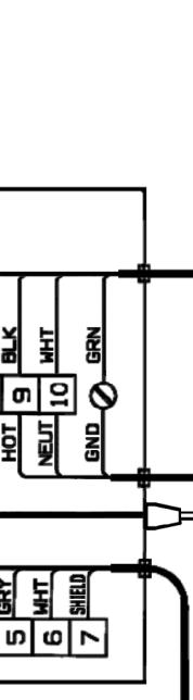
20 2.3 Installation Wiring Perform the following procedures for installing interconnecting wiring (see Figure 7 for stand-alone installation and Figure 8 for master/ /slave installation): a) Connect all wiring between the flashhead and the power supply using Honeywell supplied cable P/N * The wires in this cable are color codedd and connect to the numbered terminals of flashhead TB1 corresponding numbered terminals of the power supply TB2. b) Connect all wiring that interconnects between the steady burning red side lights and power supply using the Honeywell supplied cable WC2312CLT or WC2312DLT or equivalent #12 AWG cord (color coding may be different than listed below). The wires in this cable are connected to the numbered terminals of TB1 as follows: Black Wire of Cable to TB1-11, 12VAC Line out to Sidelight Level 1 Orange Wire of Cable to TB1-12, 12VAC Line out to Sidelight Level 2 Red Wire of Cable to TB1-1, Neutral return from Sidelight Level(s) Blue Wire of Cable to TB1-Ground Lug c) Connect wiring between the external photocell and the power supply using #12 AWG wire. The wires in this cable are connected from TB1, as follows: Black wire of the photocell to TB1-2 Red wire of the photocell to TB1-1 White wire of the photocell to TB1-Ground lug d) For structures with 2 or more systems, connect the wiring between the master power supply and slave power supply using Honeywell cable * This cable has a total of 1 conductors and can be used to distribute power and timing pulses and consolidates alarm functions to and from slave power supplies. For details consult Honeywell Tech Support at
21 2.4 GPS Sync Wiring (OPTIONAL) Perform the following procedures for installing interconnecting wiring (see Figure 9 for System installation and Figure 1 for Power Supply internal GPS wiring installation): a) Connect all wiring between the flashhead and the power supply using Honeywell supplied cable P/N * The wires in this cable are color codedd and connect to the numbered terminals of flashhead TB1 corresponding numbered terminals of the power supply TB2. b) Connect all wiring that interconnects between the steady burning red side lights and power supply using the Honeywell supplied cable WC2312CLT or WC2312DLT or equivalent #12 AWG cord (color coding may be different than listed below). The wires in this cable are connected to the numbered terminals of TB1 as follows: Black Wire of Cable to TB1-11, 12VAC Line out to Sidelight Level 1 Orange Wire of Cable to TB1-12, 12VAC Line out to Sidelight Level 2 Red Wire of Cable to TB1-1, Neutral return from Sidelight Level(s) Blue Wire of Cable to TB1-Ground Lug c) Connect all wiring between the GPS Sync and the power supply using Honeywell supplied cable P/N 4274-( ) for GPS connector location (see Figure 6). 2.5 GPS Sync Installation (OPTIONAL) The GPS (part number 4275) unit should be mounted outdoors with a clear view of the South sky. A 25 to 35-feet GPS cable can be ordered as needed. Nearby obstructions to the South should be avoided. The unit should be mounted on a flat vertical surface or a pole (see Figure 12). a) Switch S1-4 on the Sync/Monitor Board should be in the ON (slave) position for all GPS-controlled units. b) Typically requires one of the following photocells (sold separately). Important: If photocell is not equired, socket cover must be left in place to prevent water entry into GPS unit. 1. Photocell (for Red Beacons, fc) 2. Photocell (for White or Dual Beacons, 1 3 fc) 2
22 WARNING Lethal high voltages are present in the conductors between the power supply and the flashhead. There should be one continuous run of cable from flashhead to power supply. Under no circumstan nces should these conductors be spliced. Figure 7. System Wiring Diagram 21
23 WARNING Lethal high voltages are present in the conductors between the power supply and the flashhead. There should be one continuous run of cable from flashhead to power supply. Under no circumstan nces should these conductors be spliced. Figure 8. System Wiring Diagram for Master / Slave Units 22


24 Figure 9. System Wiring Diagram for Units with GPS 23


25 Figure 1. Internal Wiring Diagram for Unit with GPS 24
26 Figure 11. GPS Flash Rate Dip Switch Positions 25


27 Figure 12. GPS Pole Mount (Optional) 26
 to ensure that they are properly seated in their")
28 Figure 13. GPS Unit (Optional) 2.6 Final Check Before applying power to the equipment, check all relays and printed circuit boards (PCBs) to ensure that they are properly seated in their sockets. Check to ensuree that any user-installed wiring does not interfere with relay operation when covers are closed. 27
29 3. OPERATION 3.1 General This section provides information for operating the lighting system during normal operating conditions. 3.2 Operating Procedures After the system has been wired according to the instructions in Section 3, it is ready for normal operation. The flashhead assembly should be closed and secured. When the cover of the power supply is closed so that the interlock switch is engaged and power is applied, the system will begin to operate. If theree is sufficient light and the ambient light sensor is mounted correctly, the system will automatically switch to the correct mode after a 1 to 2 minute delay. The delay protects against unwarranted switching due to momentary changes in the light reaching the sensor. If a GPS sync unit is used the GPS sync indicator should begin flashing at power-up, but allow 2 minutes for full sync operation. The built-in antenna requires clear view of the south horizon (in the northern hemisphere) up to 5 degrees elevation (position the antenna straight up). 3.3 Status Indicators Refer to Table 4 LED status indicators. 28
30 Indicator Control power ON High Voltage Neon Lamp Flashhead Alarm Status LED Sync Out LED Sync In LED Flashtube Status LED Side light Failure LED(s) GPS SYNC Green LED GPS SYNC Yellow LED GPS SYNC Red LED Table 4. LED Status Indicators Description Located on the control panel (top center), this indicator is illuminated whenever input power is present and the power supply interlock switch is engaged. Located on the high voltage circuit (top) board, this lamp indicates that the high voltage circuits are active. Extreme caution should be used if the neon lamp is on. Located on the sync/ /monitor (middle) board, this LED will be green when the flashhead is operating correctly. If the LED is off, the system is in alarm mode. Located on the sync/ /monitor (middle) board, this LED blinks red to indicate that a sync signal has been generated. In a multiple flashhead system, only the sync/monitor board that is set as the master will blink this LED Located on the trigger/control (bottom) board, this LED blinks green to indicate thatt a sync signal has been received from the sync/monitor board. Located on the trigger/control (bottom) board, this LED is red if the red flashtubes are in operation. If the white flashtubes are being used, the LED is off. Located on the alarm card (AC) inside the lid of power supply, these LEDs turn red to indicate a side light lamp failure. This LED is green when the sidelights are operating properly. LED2 will be lit RED during night operation when only one sidelight level is in use. Located on the bottom of the GPS sync unit (Refer to Figure 13), this LED will turn green when power is on. Located on the bottom of the GPS sync unit (Refer to Figure 13), this LED will turn yellow when unit has locked onto a satellite signal. Located on the bottom of the GPS sync unit (Refer to Figure 13), This LED will flash red with each sync pulse. 29
31 4. FUNCTIONAL DESCRIPTION 4.1 General The purpose of Section 5 is to provide a general overall description of how the equipment components function with relation to each other (equipment as a whole) and functional description of how individual units or subassemblies of the equipment function. 4.2 Major Assemblies The AC main power input to the power supply is converted to approximately 1, VDC to bias the flashtubes in the flashhead and to charge the energy storage capacitors. The ambient light sensor sends correct control signals to the power supply to automatically change the intensity of the flashhead and control the red incandescent side lights. The main power to the power supply is applied to the control and logic circuitry, thereby activating relays that determine the intensity of the flashhead. Logic circuits in the power supply generate a timing signal that controls the rate of flash. The GPS sync signal disables the internal clock circuit. The flash occurs at the same time as the sync signal. Test switch located on the switch panel allows the system to operate in either day or night mode. This switch should be left in the AUTO position for photocell operation. 4.3 Functional Description of Subsystemss Lighting System Flashhead and Power Supply The main AC input power is transformed to high voltage DC and stored in capacitors. The trigger circuit fires the flashtube, in parallel with the capacitors. This discharges the capacitors, producing a flash of light. Changing the capacity for energy stored between flashess varies the intensity of the light. The flashtube extinguishes when current from the capacitors is too low to support the arc. The power supply short circuit current is set below the minimum tube current to prevent continuous conduction. The capacitors then recharge for the next flash. Input power is applied to the primary of the ferroresonant power transformer (T1) when the flashhead and cover interlocks are closed. The high voltage output of T1 is rectified and charges the energy storage capacitors. In the day mode, normal operation has the interlock relay (K1) energized while the day/ /night relay K2 is de-energized. Capacitors C2 and C3 in the high voltage circuit are kept charged. With this amount of capacitance in the circuit and DC voltage provided, sufficient energy is discharged through flashtube to produce an effective intensity of 2, candelas ( ±25%). In the night mode (low intensity), 12 VAC is supplied from the photocell and applied to the power supply (on TB1-1) and to the day/night relay (K2). When K2 is energized, its contacts will removee C2 from the high-energy circuit and discharge it through R2 and R4. Now only C3, with R3 in series, 3
32 is in the tube circuit. This provides the energy required to produce the effective intensity of approximately 2 candelas. Concurrently, 12 VAC Figure 14. FG3B Lighting System Schematic Diagram 31
33 Figure 15. FG2B Lighting System Schematic Diagram 32
34 is applied to pin 8 of the trigger control PCB, switching logic from single shot to burst mode. The AC voltage is also applied to pin 32 of the sync/monitor PCB, establishing the number of red FPM Side Lights The AC night control voltage at TB1-1 operates a red light control module consisting of a SPDT relay and an alarm card. These components power and monitor any red obstruction lights used in conjunction with the lighting system, indicating the loss of any incandescent bulb or LED fixture. The module will control up to two levels of four 12 V steady burning sidelights High Voltage PCB The high voltage PCB consists of a three-diode-per-leg bridge and two 3- diode circuits. High voltage AC from the power transformer is provided to the HV PCB connector. This high AC voltage is full wave bridge rectified by the bridge. Neon lamp, LP1, lights whenever high voltage is present Trigger Control PCB The function of the Trigger Control PCB is to provide a synchronized trigger pulse to the primary of a trigger transformer located in the flashhead. A single pulse in the day mode and a burst in the night mode. DIP switches set the burst flashes individually for red, SW1, and white operation, SW2. 33
35 SW1 OFF ON SW OFF Disable ON Enable Day Mode Day Mode 32 6 Not Used - settingss per shaded areas Figure 16. FG3B Trigger Control Switch Settings SW1 OFF ON SW2 OFF ON Disable Enable Day Mode Day Mode Not Used - settingss per shaded areas Figure 17. FG2B Trigger Control Switch Settings SW1 OFF ON SW2 OFF ON Disable Enable Day Mode Day Mode Not Used - settingss per shaded areas Figure 18. FG29B Trigger Control Switch Settings 34
36 4.3.5 Sync/Monitor PCB The function of the Sync/Monitor Board is to generate a sync pulse for the trigger control board; to select AC 5 or 6 Hz or DC input power, master or slave operation; and to detect faulty operation of the lighting system such as missing or out of sync flashes. The Day Mode flash rate is set at 4 FPM per FAA equirements and cannot be changed. The Nite Mode flash rate can be adjusted between 2 4 FPM per FAA requirements. Switch S2 allows for field adjustment of the nite flash rate. See Figure 19 for switch settings. Field adjustment can also be made at Switch S1 for the following: AC or DC voltage 5 Hz or 6 Hz Night Light (White or Red) Master or Slave The flashes per minute (FPM) for the red night system can be field adjusted by setting S2 to equal the number in the FPM table: Power Line Freq. Hz DC Flashes Per Minute FPM Figure 19. Sync/Monitor Switch Settings The switch settings shown in Figures 2, 21, and 22 represent the units following characteristics with the Input Phase AC Input Frequency 6 Hz Stand-alone (i.e. Master) Same units may have different settings. If the your model does not match the units shown here, please contact Honeywell Technical Support at for specific switch settings. 35
37 S OFF AC 5 Hz White Night Master Sync Card ON DC 6 Hz Red Night Slave Sync Card S settings OFF s per shaded a ON areas Figure 2. FG3B Sync/Monitor Switch Settings S OFF AC 5 Hz White Night Master Sync Card ON DC 6 Hz Red Night Slave Sync Card S settings OFF s per shaded a ON areas Figure 21. FG2B Sync/Monitor Switch Settings S OFF AC 5 Hz White Night Master Sync Card ON DC 6 Hz Red Night Slave Sync Card S OFF ON settingss per shaded areas Figure 22. FG29B Sync/Monitor Switch Settings 36
38 4.4 GPS SYNC The function of the GPS sync is to generate a sync pulse for the trigger control board. The Day Mode flash rate is set at 4 FPM per FAA requirements and cannot be changed. The Nite Mode flash rate can be set for 24, 3, 4 or 6 FPM. Switch S1 on the GPS unit allows for field adjustment of the night flash rate. See Figure 11 for switch positions and Figure 23 for the flash rate settings. GPS UNIT S1 = Open 1 = Closed FPM Figure 23. GPS Sync Switch Settings Switch S1-4 on the Sync/Monitor Board should be in the ON (slave) position for all GPS-controlled units. 4.5 System Failure (Alarms) Strobe Failure Fail detection during the day operation causes fault relay K1 on the Sync/Monitor board to open 1 seconds after the last normal flash. Occasional missed flashes will go undetected. The fault relay closes whenever normal operation is restored (a go condition). Fail detection during night operation in addition to opening the fault relay (fail condition) ), establishes operating conditions for white/night flashtube operation. White/night operation only occurs whenever red operation fails, and begins 1 seconds after the last flash of the red lamp. The preset white/night flashing conditions are: 4 FPM giving an equivalent light output of 2, candelas. Operation in this mode continues until day mode is called for, or power is interrupted. When day operation is called for by the photocell, the fail detection system verifies proper day operation, closing the fail relay K1. A test button switch is located on the top edge of the PCB. This switch grounds out the flash signal when held closed, thus simulating flash failure. To operate, hold the test button closed for longer than 1 seconds. Single-pole double-throw relay contacts are available (12E45-2) for monitoring. Continuity between TB1-7 and TB1-8 is maintained closed while TB1-6 and 8 is open as a go condition. Continuity between TB1-6 and 8 represents a fault condition, while TB1-7 and 8 is open. 37
39 4.5.2 Alarm Card (AC) The side light alarm provides fault indicators when one or more incandescent lamps or LED fixtures fail. When a lamp fails, a decrease in current is sensed and the alarm card transfers to the alarm mode. This is reflected in two ways. The red LED lights and the relay transfers to provide an open circuit between the common (wiper) and the normally closed contacts and a closed circuit between the wiper and the normally open contact. Replacement of a failed lamp resets the alarm output and extinguishes the LED. During the day mode when the red lights are not on, the module does not report an alarm. MODE DAY NIGHT RELAY1 LED1 RELAY2 LED2 RELAY1 LED1 RELAY2 LED2 OK C1-NC1 GREEN C1-NC1 GREEN C1-NC1 GREEN C1-NC1 GREEN (RED IF UNUSED) STATUS ALARM C1-NO1 RED C1-NO1 RED C1-NO1 RED C1-NO1 RED Table 5. Side Light Alarm Module Fault Indicators 38
40 5. TROUBLESHOOTING AND CORRECTIVE MAINTENANCEE 5.1 General The purpose of Section 6 is to provide procedures that enable the troubleshooter to isolate and correct the causes of malfunctions. Such corrective action may be in the form of an immediate fix of a problem or may direct the troubleshooter to a corrective maintenance procedure for adjustment or repair. 5.2 Tools Required Flat head screwdriver 5/16 nut driver to open flashhead Clean gloves to use when changing flashtubes Digital multimeter w/ Ohm reading and 5 VDC capacity NE2 neon light, HONEYWELLL part number * Short piece of wire for jumper (Approx. #12 wire gauge) 5.3 Troubleshooting Procedures and Tables Logic diagrams direct maintenance personnel to associated tables listing the malfunction, test, and corrective maintenance action to perform. 39
41 5.4 Flashhead (Strobe) Problems Logic Diagram Utilize the following logic diagram to determine the most correct course of maintenance action to perform to troubleshoot the flashhead when strobe problems occur. Utilize Table 6 in conjunction with the logic diagram. 4
42 Table 6. Flashhead (Strobe) Problems Corrective Maintenance Malfunction Test Corrective Action Section 1 Flashhead does not operate in any mode, no LEDs on. Input power incorrect. Measure input power it should be with ±1% of Supply correct input power. required voltage. Power supply interlock switch not engaged. Press the power supply interlock switch and hold it down. Close the unit the system should operatee properly. Blown F1 (6 Amp) fuse, or transformer (63mA) fuse. Remove all three PCBs and check for damage. Remove Replace the defective component. the photocell wiring from TB1-1 and TB1-2. Perform flashhead isolation test and check for improper resistances. Leave the flashhead cable disconnected, replace the fuse and apply power. Replace the strobe cable, the photocell wiring, and the PCBs one by one to determine which one will blow the fuse. Section 2 Flashhead does not operate in any mode, control power indicator on, high-voltage neon lamp off. Flashhead interlock switch not engaged. Remove the flashhead wires TB2-5 and TB2-6 (gray and white), and measure Re-seamaking sure the interlock switch engages when the the flashhead cover, resistance between them - it cover is closed. If the system should be less than 5Ω. stilll does not have continuity between TB2-5 and TB2-6, replace the flashhead interlock switch and inspect the strobe cable for damage. Relay K1 not energizing. When the interlock switches Replace the K1 relay. are engaged, the K1 relay should energize. If not, measure for 12 VAC across the relay coil. Alternatively, remove the connectors and check resistance acrosss the K1 coil it should be 3Ω. 41
43 Faulty high-voltage PCB. Visually check the traces on the high-voltage PCB. Check for any shorted diodes. Use diode check function on multimeter if available. Replace the high-voltage PCB. Section 3 Flashhead does not operate in any mode, control power indicator on, high-voltage neon lamp on. Trigger control PCB defective or incorrect DIP switch setting. Perform flashhead isolation test and power supply isolation test. Compare trigger PCB DIP switch settings with default settings Set DIP switches according to specifications. If no trigger is observed when performing Trigger Test, replace the trigger control PCB. in technical manual. Insufficient trigger voltage to If tower height is greaterr than Leave the connector at E14. the flashhead. 34 feet, remove the connector at terminal E13 on the motherboard, and connect it to E14. This will boost the voltage to the flashhead by approximately 1%. Section 4 Flashhead operates properly in day mode, but at night goes into white backup night mode and trips the strobe alarm. Red flashtube/ red trigger Swap the wires between If system flashes red night transformer faulty. TB2-3 and TB2-4. Put the unit in night mode. mode through the white flashtube, with the strobe After this testt return the alarm off, replace the red wires to their original flashtube and/ /or red trigger positions. transformer. Green LED on Sync Board = ON Trigger control PCB faulty. Perform power supply isolation test to check for Replace the trigger control PCB. Diode PCB DB1 faulty. trigger pulses. Remove the two mounting screws on the control panel. Disconnect DB1, and measure resistance both ways across each diode. Make sure no diodes have shorts. If shorted, DB1 is faulty. Note: The diode PCB DB1 is located under the control panel where the test switches are. Replace DB1. Section 5 Flashhead operates properly in night mode, strobe alarm is off. No flash in day mode, strobe alarm is on. 42
44 Day Enable switch SW2-5 on Set SW2-5 on the trigger the trigger control PCB set to control PCB to ON, then test OFF. the unit in day mode. White flashtube and/or white Swap the wires on TB2-3 trigger transformer faulty. and TB2-4 Put the unit in day mode. After performing this test return the wires to their original position. Trigger control PCB faulty. Perform power supply isolation test to check for trigger pulses. Diode PCB DB1 faulty. Remove the two mounting screws on the control panel. Disconnect DB1, and measure resistance across each diode. Replace DB1 if any diodes have shorted. Note: The diode PCB DB1 is located under the control panel where the test switches are. Leave SW2-5 ON. If system flashes day mode through the red flashtube, with the strobe alarm off, replace the white flashtube and / or white trigger transformer. Green LED on Sync Board = ON. Replace the trigger control PCB if test fails. Replace DB1. Section 6 System willl not switch between day and night modes correctly. Mode switches in wrong position. Put rocker switch (S2) in Auto position. Illuminate the If the system responds to the switch changes, but not to photocell for a minute or so the photocell, replace the to approximate daytime photocell. conditions. The system should go into day mode. Cover the photocell with a thick, dark, opaque material, to approximate nighttime conditions. Wait for a minute or so. The system should go into night mode. If the system does not respond correctly to the photocell, try changing modes by using the rocker switch on the control panel. 43
45 K2 mode relay malfunctioning. Set the day mode switch to Remote, night mode to Test. Replace the K2 relay. The K2 relay should energize. If not, measure for 12 VAC across the relay coil. Alternatively, remove the connectors and check resistance across the K2 coil it should be at 3Ω. Section 7 System operates properly in day mode, but at night goes into white backup night mode, no strobe alarm. Sync PCB switch S1-3 set to Set S1-3 to red night mode ON position. white night mode OFF position. Section 8. Flashhead flashing slow (<2 FPM), in backup mode at night, and strobe alarm on. Not configured or defective sync monitor PCB. Ensure the DIP switchess on the sync monitor PCB are set correctly per the manual. If the DIP switch settingss are correct, and the red LED is not pulsing at 4 FPM, Visually verify that the red replace the sync monitor LED on the sync monitor PCB. PCB is pulsing at 4 FPM. Current sense transformer wires are crossed, or current sense transformer is defective. The brown wire should connect to the capacitor side of the current sense transformer, the purple wire If the transformer wires are correct, replace the current sense transformer. towards TB2. Defective GPS Sync unit Swap with a known good unit Replace the GPS sync unit. Section 9 Night mode very bright, red, no alarms. Relay K2 open. Put the system in night Replace the K2 relay. mode. Check for 12 VAC across the coil of the K2 relay. Alternatively, remove the connectors and check resistance across the K2 coil it should 3Ω. 44
46 5.5 Multiple Strobe Problems Logic Diagram Utilize the following logic diagram to determine the most correct course of maintenance action to perform and to troubleshoot the flashhead when multiple strobe problems occur. Utilize Table 7 and the section listed in the logic diagram. 45
47 Table 7. Multiple Strobe Problems Corrective Maintenance Malfunction Test Corrective Action Section 1 Flashheads are operating, but out of sync. At night, slave units in white backup night mode instead of normal red. Sync monitor PCB on the DIP switch S1-4 in the master unit should be set to OFF. master power supply not configured as master. Interconnecting wire between master and slave power supplies missing. Inspect wiring between power supplies. TB1 position 3 should be daisy-chained between each power supply, Install interconnecting wiring. per the installation wiring diagram. Sync/Monitor S1-4 is OFF, GPS Sync Unit Defective or Incorrectly wired. Check S1-4 position. Inspect wiring. Swap the GPS Sync Unit with known good unit. Turn ON S1-4. Correct wiring. Replace the GPS Sync Unit. Section 2 All lights are in sync, but there is a double-flash, or flashing faster than 4 FPM. More than one sync monitor PCB is set as master. Inspect the DIP switchess on each sync monitor PCB. In Reconfigure sync monitor PCBs. Refer to the manual the master power supply, for correct positions. DIP switch S1-4 should be set to OFF, which is the master position. In all the other power supplies, this switch 4 should be set to ON, which is the slave position Section 3 Master unit switches to night mode at night, but slave units remain in day mode. Interconnecting wire between master and slave power supplies missing. Inspect wiring between power supplies. TB1 position 1 should be daisy-chained Install interconnecting wiring. between each power supply, per the installation wiring diagram for multiple units. 46
48 5.6 Side Light Problems Logic Diagram Utilize the following logic diagram to determine the most correct course of maintenance action to perform and to troubleshoot the flashhead when side light problems occur. Utilize Table 8 and the section listed in the logic diagram. Table 8. Side Light Problems Corrective Maintenancee Malfunction Test Corrective Action Section 1 Side lights not operating at night. Verify correct wiring per installation diagram. On systems with more than one power supply, note that each side light module should run two levels of side lights F3 fuse open. Remove the F3 fuse. Check Reseat / Replace. for continuity. Power supply rocker switch is in the wrong position. Make sure rocker switch is in the Auto position, and that the photocell is not illuminated (if necessary, temporarily cover it to simulate nighttime). Section 2 Side lights in alarm Side light lamp burned out. On the alarm card (AC1) set Replace burned out side the DIP switches to monitor light. 1 (one) less side light than the current number (reference switch setting positions in manual). Alternatively, measure the current goingg out to your side lights though the wire on TB1-11 or TB1-12. Compare your current reading to the nominal (expected) current level to see how many side lights you have operating. Wrong DIP switch setting on the side light alarm module. Match DIP switch setting on AC1 at switch(es) SW1 or SW2 with the actual number of side lights to monitor. Low input voltage. Check input voltage it Increase input voltage. should with ±1% of required voltage. 47
49 5.7 Flashhead Isolation Test Turn off the input voltage at the circuit breaker to the power supply. Disconnect the seven conductor cable from power supply at terminal block TB2. Using an Ohmmeter, check the resistance between the conductors of the disconnected flashhead cable, and compare to the expected values: FG2B Single Flashhead Readings (cable disconnected from power supply) #1 Red: Open to all conductors #2 Brown: Open to all conductors #3 Black: < 5Ω to blue, open to all others #4 Blue: < 5Ω to black, open to all others #5 White: < 5Ω to gray, open to all others #6 Gray: < 5Ω to white, open to all others #7 ground: Open to all conductors FG3B Dual Flashhead Readings (cable disconnected from power supply) #1 Red: Open to all conductors #2 Brown: < 5Ω to blue & black, open to all others #3 Black: < 5Ω to brown & blue, open to all others #4 Blue: < 5Ω to brown & black, open to all others #5 White: < 5Ω to gray, open to all others #6 Gray: < 5Ω to white, open to all others #7 ground: Open to all conductors Flashhead Test Results a) Correct readings do not ensure that the flashhead and cable are good, but this is a quick check for obvious problems. b) If the readings above are correct, proceed to the Power Supply Isolation Test. c) If the resistance between #5 (gray) and #6 (white) is greater than 5Ω, or is open, suspect that the flashhead interlock switch is not depressed. 48
50 d) For other inconsistencies with the above chart, the probable causess are incorrect wiring, or conductors shorted and/or opened. If possible, disconnect the flashhead cable at both ends and perform a Megger test with a Megohm Meter. 5.8 Power Supply Isolation Test Leave the seven conductor strobe cable disconnected from the power supply at terminal block TB2. Install a jumper wire between terminals 5 and 6 to simulate the interlock switch being depressed. Install a neon lamp (HONEYWELLL Part # ) across the trigger output. For the Day Mode, install the neon lamp in terminals 2 and 4 on TB2. For the Night Mode, install the neon lamp in terminals 2 and 3 on TB2. Apply power to the system and insure the following: Voltage Measureme ents Using a voltmeter, measure the voltages of the conductors to ground terminal 7. Check the measurements in both day and night modes, and compare to the expected values: Power Supply Measurements #1, Red: +5 VDC to ground #4, Blue: 5 VDC to ground #2, Brown: 5 VDC to ground #5, Gray: 12 VAC to ground #3 See Below #6, White: 12 VAC to ground If either the red or the brown conductor does not have +5 VDC or 5 VDC respectively, there is most likely a problem in the T1 transformer, the high voltage board, or a capacitor has failed. Check the input and output voltage of the transformer. Check the high voltage board for bad diodes. Check each capacitor for the proper value. If your meter will not measure capacitance (Farads) then check the capacitors for opens or shorts Neon Lamp Flash Rate With the power supply in day mode, you should see one quick flash at a flash rate of 4 FPM. When the system is put into night mode, you should see a long burst of flashes for a few seconds. Then the lamp should begin flashing short bursts of flashes. This happens becausee the power supply can tell that the red flashtubes are not operating, so it tries to go into backup white night mode. If the neon tube will never flash, you most likely have a problem with the trigger board. Check the DIP switch settings with those in the manual, and replacee the board if necessary. If the neon tube flashes slowly, you most likely have a problem with the sync board. Check the DIP switch settings with those in the manual, and replacee the board if necessary. 49
51 If the neon lamp is flashing correctly, and the voltages are correct, the power supply is probably working, and the problem is likely in the flashhead or the strobe cable. Remove neon lamp & jumper from TB2 before reconnecting the flashhead. 5.9 Flashhead Maintenance No special or preventive maintenancee is required for the flashhead, but only thatt which can be performed on an as-needed basis. Should it become necessary to replace the flashtubes, the following instructions must be adhered to: WARNING Ensure that the power is OFF and the capacitor bank has been dischargedd before opening the flashhead. a) Loosen the eight (8) bolts securing the globe only enough to turn the black retainers. The bolts will fall out if they are loosened excessively. b) After turning the black retainer s 9 degrees, lift the globe approximately twelve inches. When the top extent is reached, rotate the globe slightly (counterclockwise) to move the lift guide into its support position. 5


")


52 c) The two strings of threee flashtubess are attached at both ends to sockets with connectors. See Figure 24. Disconnect both ends of the flashtube assembly to be replaced. Figure 24. Flashtube Assembly with Ferrite Beads d) Gently remove each flashtube from its supports, being careful not to break it. See Figure 25. Disconnect ferrite suppressors from quick-on fasteners. Figure 25. Attachment of Ferrite Beads with Quick-On Fasteners 51

 Remove the new flashtubes from their container and connect the")

 Working counterclockwise from the red socket, insert each")


53 CAUTION Use a clean pair of gloves to handle the flashtubes. Fingerprints or contaminationn on the glass will adversely affect reliability of flashtubes. e) Remove the new flashtubes from their container and connect the red-marked lead to the red socket. See Figure 26. Carefully connect ferrite suppressors to their quick-on fastener grounding lugs. f) Working counterclockwise from the red socket, insert each flashtube into its pair of supports. Apply equal pressure TO THE METAL END CAPS ONLY (as shown in the illustration below) so that the ends of each flashtube are simultaneously snapped into place. THE FLASHTUB BE ASSEMBLY IS EXTREMELY FRAGILE, especially at the junction between glass and metal. Handle the flashtubess in a manner that avoids stressing this critical seal. Figure 26. Flashtube Insertion g) Connect the black-marked lead to the black socket. h) Rotate the globe slightly (clockwise) to realign the lift guide in its vertical travel slot. Push down on the globe to re-seat it on the gasket. i) Turn each black retainer back 9 degrees and tighten the bolts. 5.1 Power Supply and Light Sensor Maintenance The power supply and ambient light sensor require no special maintenance. The light sensor should be checked and cleaned periodically because too much dirt on the window can cause it to malfunction. 52
FlashGuard 3000B Dual Lighting System Troubleshooting Guide
 FlashGuard 3000B Dual Lighting System Troubleshooting Guide Table of Contents Section Flashhead (Strobe) Troubleshooting Flowchart 1 Multiple Strobe Troubleshooting Flowchart 2 Sidelight Troubleshooting
Troubleshooting Guide For FG3000 Dual Medium Intensity Lighting System
 Troubleshooting Guide For FG3000 Dual Medium Intensity Lighting System TABLE OF CONTENTS SECTION 1.0 - GENERAL INFORMATION...1 1.1 Scope...1 1.2 General Description...1 1.3 Safety Precautions...2 1.4 Honeywell
For. Manual No. Rev. B. Alll Rights Reserved
 Troubleshooting Guide For FG3000 Dual Medium Intensity Lighting System Manual No. Hughey & Phillips 136 East Court Streett Urbana, OH 43078 Phone: (937) 652-3500 Fax: (937) 652-3508 Toll Free: 877-285-4466
Training Guide For FG3000 Dual Medium Intensity Lighting System
 Training Guide For FG3000 Dual Medium Intensity Lighting System Manual No. MPR-00000009-001 Honeywell Airport Systems 2162 Union Pl. Simi Valley, CA 93065 Phone: (805) 581-5591 Fax: (805) 581-5032 http://www.oblighting.com
HUGHEY & PHILLIPS, LLC.
 HUGHEY & PHILLIPS, LLC. Installation and Operation Guide HORIZON MEDIUM INTENSITY DUAL LED LIGHTING SYSTEM CONTROLLER FAA TYPES A1, D1, & E1 MANUAL EPM-00000044-001 Revision F Hughey & Phillips, LLC. 240
Models NFPA 1221-A, NFPA 1221-B Public Safety DAS Annunciator Panel. Revision E 61117
 Models NFPA 1221-A, NFPA 1221-B Public Safety DAS Annunciator Panel Revision E 61117 CAUTION: (Read This First) This panel has been designed to make it nearly bullet proof to mistakes made when wiring
ACSI AO ELECTRIC LATCH RETRACTION CONTROLLER INSTALLATION INSTRUCTIONS I.D. 1089, REV. F
 II 1400-2 ACSI 1406-04-AO ELECTRIC LATCH RETRACTION CONTROLLER INSTALLATION INSTRUCTIONS I.D. 1089, REV. F INSTALLATION Transformer Model BE31763001 by Basler Electric, Transformer Model 2010028 by Galaxy
Public Safety DAS Annunciator Panel
 Public Safety DAS Annunciator Panel 120 VAC Models: 1221-A, 1221-B, 1221-C Revision D 91117 48 VDC Models: 1221-A-48, 1221-B-48, 1221-C-48 24 VDC Models: 1221A-24, 1221-B-24, 1221-C-24 CAUTION: (Read This
ITC 2000 HEATING CONTROL CABINET. Installation & Operation Manual
 ITC 2000 HEATING CONTROL CABINET Installation & Operation Manual VTI, Incorporated 24 McMillan Way Newark, DE 19713 Phone (302) 738 0500 FAX (302) 738 6594 Revision Level 0.03 Manual No. 90003314 June,
Model 17A00 Expansion Enclosure
 HOME AUTOMATION, INC. Model 17A00 Expansion Enclosure Installation Manual Document Number 17I00-1 Rev A March, 2002 Home Automation, Inc. Model 17A00 Expansion Enclosure Installation Manual Document Number
1. PURPOSE. This advisory circular (AC) contains the Federal Aviation Administration (FAA) specification for obstruction lighting equipment.
 contains the Federal Aviation Administration (FAA) specification for obstruction lighting equipment.") U.S. Department of Transportation Federal Aviation Administration Advisory Circular Subject: SPECIFICATION FOR OBSTRUCTION LIGHTING EQUIPMENT Date: 10/19/95 Initiated by: AAS-200 AC No:150/5345-43E Change:
U.S. Department of Transportation Federal Aviation Administration Advisory Circular Subject: SPECIFICATION FOR OBSTRUCTION LIGHTING EQUIPMENT Date: 10/19/95 Initiated by: AAS-200 AC No:150/5345-43E Change:
FLT93 Installation, Operation and Troubleshooting Guide
 FLT93 Installation, Operation and Troubleshooting Guide Pre-Installation A. To get the best results from the instrument, the instrument should be mounted 20 pipe diameters downstream from any valve, pipe
4300 WINDFERN RD. SUITE 100 HOUSTON, TX VOICE (713) FAX (713) WEB: twrlighting.com IMPORTANT!!!
 FAX (713) WEB: twrlighting.com IMPORTANT!!!") 4300 WINDFERN RD. SUITE 100 HOUSTON, TX 77041-8943 VOICE (713) 973-6905 FAX (713) 973-9852 WEB: twrlighting.com IMPORTANT!!! PLEASE TAKE THE TIME TO FILL OUT THE FORM COMPLETELY. FILE IN A SAFE PLACE.
4300 WINDFERN RD. SUITE 100 HOUSTON, TX 77041-8943 VOICE (713) 973-6905 FAX (713) 973-9852 WEB: twrlighting.com IMPORTANT!!! PLEASE TAKE THE TIME TO FILL OUT THE FORM COMPLETELY. FILE IN A SAFE PLACE.
Installation, Operating and Maintenance Manual
 STATUS ZONES CONTROLS FIRE FAULT DISABLED FIRE 1 2 3 4 5 6 7 8 TEST FAULT DISABLED 1 5 BUZZER SILENCE RESET 1 2 TEST 2 6 LAMP TEST 3 SUPPLY 3 7 SYSTEM FAULT 4 8 SOUNDERS ACTIVATE/ SILENCE 4 FAULTS INSTRUCTIONS
DESCRIPTIVE AND INSTALLATION INSTRUCTION MANUAL FOR MODEL G1000 AND H1000 SERIES ANNUNCIATORS
 DESCRIPTIVE AND INSTALLATION INSTRUCTION MANUAL FOR MODEL G1000 AND H1000 SERIES ANNUNCIATORS SEEKIRK, INC. 2420 Scioto Harper Dr. Columbus, OH 43204 Tel: (614) 278-9200 FAX: (614) 278-9257 email: seekirk@seekirk.com
DESCRIPTIVE AND INSTALLATION INSTRUCTION MANUAL FOR MODEL AH1000, BH1000, AND EH1000 SERIES ANNUNCIATORS
 DESCRIPTIVE AND INSTALLATION INSTRUCTION MANUAL FOR MODEL AH1000, BH1000, AND EH1000 SERIES ANNUNCIATORS SEEKIRK, INC. 2420 Scioto Harper Dr. Columbus, OH 43204 Tel: (614) 278-9200 FAX: (614) 278-9257
ACSI MODEL 1410 POWER SUPPLY INSTALLATION INSTRUCTIONS
 II 1400-3 ACSI MODEL 1410 POWER SUPPLY INSTALLATION INSTRUCTIONS Features: For use with doors or groups of doors that must interlock with each other to regulate control of accessing one area from another,
STATUS ALARM ALARM HISTORY POWER HISTORY RESET
 Instruction Manual Model 1582-70L2 RF Switch June 2011, Rev. D CH1 AUTO CH2 SWITCH 1 2 1 2 STATUS 1 2 MODEL 1582 SWITCH CROSS TECHNOLOGIES INC. CH1 ONLINE MANUAL SELECT CH2 SWITCH MANUAL REMOTE ONLINE
IMPORTANT!!!! MODEL # E-1DB 1/13/2000
 1/13/2000 IMPORTANT!!!! PLEASE TAKE THE TIME TO FILL OUT THE FORM COMPLETELY. FILE IN A SAFE PLACE. IN THE EVENT YOU EXPERIENCE PROBLEMS WITH OR HAVE QUESTIONS CONCERNING YOUR CONTROLLER, THE FOLLOWING
www. ElectricalPartManuals. com GADD MKIII Ground Fault Indication System Instruction Manual Ground Fault Protection
 Ground Fault Protection GADD MKIII Ground Fault Indication System Instruction Manual 7615 Kimbel Street, Mississauga, Ontario Canada L5S 1A8 Tel: (905)673-1553 Fax: (905)673-8472 Toll Free: 1-888-RESISTR
SAFETY INFORMATION AND WARNINGS
 This manual refers to the Model SST-3 control panel manufactured since October 31, 2013, which uses a universal (100 277 VAC; 50/60 Hz) power supply. Older units use a voltage-specific power supply and
MODEL 8143 SIGNAL SELECTOR INSTALLATION AND OPERATION MANUAL
 MODEL 8143 SIGNAL SELECTOR INSTALLATION AND OPERATION MANUAL 95 Methodist Hill Drive Rochester, NY 14623 Phone: US +1.585.321.5800 Fax: US +1.585.321.5219 www.spectracomcorp.com Part Number 8143-5000-0050
MAINTENANCE & TROUBLESHOOTING GUIDE LEAK ALARM CHANNEL DRY OIL WATER AUX ALARM HIGH LOW CRITICAL WATER TANK LEVEL ALARM MODEL LDE-740 ADVANCE PAPER
 PNEUMERCATOR Liquid Level Control Systems Electronic Systems Excluding LC2000 And TMS Series MAINTENANCE & TROUBLESHOOTING GUIDE 400 300 500 FUEL LEVEL LEAK MONITOR 1 200 600 OIL/GAS NORMAL WATER PNEUMERCATOR
IMPORTANT SAFEGUARDS READ AND FOLLOW ALL SAFETY INSTRUCTIONS. HZM-Series-Class I, Div 2 Battery Unit. Instalation instructions
 HZM-Series-Class I, Div 2 Battery Unit HZM-Series-Class I, Div 2 Battery Unit Instalation instructions IMPORTANT SAFEGUARDS 1 4 5 6 7 13 When using electrical equipment, basic safety precautions should
TECH SHEET DO NOT DISCARD PAGE 1. If unsuccessful entry into diagnostic mode, actions can be taken for specific indications:
 TECH SHEET DO NOT DISCARD PAGE 1 WARNING Electrical Shock Hazard Disconnect power before servicing. Replace all parts and panels before operating. Failure to do so can result in death or electrical shock.
www. ElectricalPartManuals. com GADP Ground Fault Indication System Instruction Manual Ground Fault Protection
 Ground Fault Protection GADP Ground Fault Indication System Instruction Manual 7615 Kimbel Street, Mississauga, Ontario Canada L5S 1A8 Tel: (905)673-1553 Fax: (905)673-8472 Toll Free: 1-888-RESISTR 737-4787
INSTALLER S & OWNER S MANUAL
 INSTALLER S & OWNER S MANUAL HVAC INSTALLER: PLEASE LEAVE MANUAL FOR HOMEOWNER DEH 3000R Part No. 4028407 Dehumidifier & Ventilation System Controller 4201 Lien Road, Madison, WI 53704 TOLL-FREE (800)-533-7533
STATUS ALARM ALARM HISTORY POWER HISTORY RESET
 Instruction Manual Model 1582-152 RF Protection Switch November 2009, Rev B. CH1 AUTO CH2 SWITCH 1 2 1 2 STATUS 1 2 MODEL 1582 SWITCH CROSS TECHNOLOGIES INC. CH1 ONLINE MANUAL SELECT CH2 SWITCH MANUAL
IMPORTANT SAFEGUARDS READ AND FOLLOW ALL SAFETY INSTRUCTIONS SAVE THESE INSTRUCTIONS. NXM Series - Survive-All. Emergency Light Unit
 Emergency Light Unit IMPORTANT SAFEGUARDS When using electrical equipment, basic safety precautions should always be followed including the following: READ AND FOLLOW ALL SAFETY INSTRUCTIONS 1. Do not
F PC and AO OUTPUT BOARDS INSTRUCTION MANUAL. Blue-White. Industries, Ltd.
 F-2000 PC and AO OUTPUT BOARDS INSTRUCTION MANUAL Blue-White R Industries, Ltd. 500 Business Drive Huntington Beach, CA 92649 USA Phone: 714-89-8529 FAX: 714-894-9492 E mail: sales@blue-white.com or techsupport@blue-white.com
SP-1000X. Panic Device Power Controller Installation Guide. Rev
 TM SP-1000X Panic Device Power Controller Installation Guide Rev. 120213 Overview: SP-1000X will operate up to two (2) 24VDC panic hardware devices simultaneously. It is designed to handle the high current
Cautions and Warnings. Introduction 4009 NAC POWER EXTENDER
 Cautions and Warnings DO NOT INSTALL ANY SIMPLEX PRODUCT THAT APPEARS DAMAGED. Upon unpacking your Simplex product, inspect the contents of the carton for shipping damage. If damage is apparent, immediately
Instruction Manual Model L2 RF Switch
 Instruction Manual Model 1582-22L2 RF Switch November 2015, Rev. A CH1 AUTO CH2 SWITCH 1 2 1 2 STATUS 1 2 MODEL 1582 SWITCH CROSS TECHNOLOGIES INC. CH1 ONLINE MANUAL SELECT CH2 SWITCH MANUAL REMOTE ONLINE
IMPORTANT SAFEGUARDS READ AND FOLLOW ALL SAFETY INSTRUCTIONS. 3LERHZ Series Class I, Div 2 Combo Unit. Installation instructions
 3LERHZ Series Class I, Div 2 Combo Unit Installation instructions 3LERHZ Series Class I, Div 2 Combo Unit IMPORTANT SAFEGUARDS 1 3 When using electrical equipment, basic safety precautions should always
Pioneer-R16 Gas Monitor Operator s Manual
 Pioneer-R16 Gas Monitor Operator s Manual Edition 7/2/97 RKI INSTRUMENTS, INC RKI Instruments, Inc. 33248 Central Ave, Union City, CA 94587 (510) 441-5656 Chapter 1: Description About the Pioneer-R16 Gas
4300 WINDFERN RD SUITE 100 HOUSTON TX VOICE (713) FAX (713) web: twrlighting.com IMPORTANT!!!
 FAX (713) web: twrlighting.com IMPORTANT!!!") 4300 WINDFERN RD SUITE 100 HOUSTON TX 77041-8943 VOICE (713) 973-6905 FAX (713) 973-9352 web: twrlighting.com IMPORTANT!!! PLEASE TAKE THE TIME TO FILL OUT THIS FORM COMPLETELY. FILE IT IN A SAFE PLACE.
4300 WINDFERN RD SUITE 100 HOUSTON TX 77041-8943 VOICE (713) 973-6905 FAX (713) 973-9352 web: twrlighting.com IMPORTANT!!! PLEASE TAKE THE TIME TO FILL OUT THIS FORM COMPLETELY. FILE IT IN A SAFE PLACE.
STATUS ALARM HISTORY ALARM RESET
 Instruction Manual Model 1582-42L Data Switch February 1999, Rev 0 CH1 AUTO CH2 SWITCH 1 2 1 2 STATUS 1 2 MODEL 1582 SWITCH CROSS TECHNOLOGIES INC. CH1 ONLINE MANUAL SELECT CH2 ONLINE SWITCH RESET MAN
4300 WINDFERN RD SUITE 100 HOUSTON TX VOICE (713) FAX (713) WEB: IMPORTANT!!!
 FAX (713) WEB: IMPORTANT!!!") 4300 WINDFERN RD SUITE 00 HOUSTON TX 7704-8943 VOICE (73) 973-6905 FAX (73) 973-9352 WEB: www.twrlighting.com IMPORTANT!!! PLEASE TAKE THE TIME TO FILL OUT THIS FORM COMPLETELY. FILE IT IN A SAFE PLACE.
4300 WINDFERN RD SUITE 00 HOUSTON TX 7704-8943 VOICE (73) 973-6905 FAX (73) 973-9352 WEB: www.twrlighting.com IMPORTANT!!! PLEASE TAKE THE TIME TO FILL OUT THIS FORM COMPLETELY. FILE IT IN A SAFE PLACE.
Beacon 200 Gas Monitor Operator s Manual. Part Number: RK Released: 6/6/08
 Beacon 200 Gas Monitor Operator s Manual Part Number: 71-2102RK Released: 6/6/08 Table of Contents Chapter 1: Introduction.................................................3 Overview.............................................................3
HOKKIM INTEGRATED AMF CONTROL BOARD MANUAL FOR MODELS: HAMF-8 AND HAMF-4
 HOKKIM INTEGRATED AMF CONTROL BOARD MANUAL FOR MODELS: HAMF-8 AND HAMF-4 INTRODUCTION Thank you for purchasing the Hokkim Integrated Automatic Mains Failure Control Board model HAMF- 8 or HAMF-4. We shall
Installation Instruction Manual
 Installation Instruction Manual ILS-D1RW-8SP ILS-D1RW-8SP-E1/E2 Dual LED Lighting Systems ILS-D1RW-8SP-D1/D2 White LED Lighting Systems ILS-D1RW-8SP-CAT Catenary Dual & White LED Lighting Systems Toll
SAVE THESE INSTRUCTIONS FOR FUTURE REFERENCE
 CHC140 Obstruction Lighting System IF 1551 Front Matter SAVE THESE INSTRUCTIONS FOR FUTURE REFERENCE Abstract This manual contains information and instructions for installing, operating and maintaining
MODEL 8144-RD CLOCK SELECTOR/DISTRIBUTION AMPLIFIER INSTRUCTION MANUAL. SPECTRACOM CORPORATION 95 Methodist Hill Drive, Suite 500 Rochester, NY 14623
 MODEL 8144-RD CLOCK SELECTOR/DISTRIBUTION AMPLIFIER INSTRUCTION MANUAL SPECTRACOM CORPORATION 95 Methodist Hill Drive, Suite 500 Rochester, NY 14623 PHONE 585-321-5800 FAX 585-321-5218 REVISIONS, IF ANY,
PRODUCT CATALOG HUGHEYANDPHILLIPS.COM
 Catalog No. 1201 O b st r u c t i o n L i g h t i n g PRODUCT CATALOG HUGHEYANDPHILLIPS.COM Lighting AT GREAT HEIGHTS For 75 Years. B ro a d c a s t Te l e c o m m u n i c a t i o n s Wi n d Tu r b i n
RELEASE DEVICES RELEASE DEVICE-WPS MODELS A/B INSTALLATION MANUAL U.L. LISTED CANADIAN LISTED CSFM: :100 GENERAL DESCRIPTION:
 RELEASE DEVICES MADE IN THE U.S.A. RELEASE DEVICE-WPS MODELS A/B INSTALLATION MANUAL U.L. LISTED CANADIAN LISTED CSFM: 7300-1418:100 GENERAL DESCRIPTION: S/N: The "WPS" World Power Series, Time Delay Release
DIAGNOSTIC GUIDE DIAGNOSTIC TEST DISPLAY FAULT/ERROR CODES IMPORTANT. Activating the Diagnostic Test Mode. Before servicing, check the following:
 TECH SHEET - DO NOT DISCARD PAGE 1 DIAGNOSTIC GUIDE Before servicing, check the following: IMPORTANT Electrostatic Discharge (ESD) Sensitive Electronics ESD problems are present everywhere. ESD may damage
P4200PM / P5000PM Remote Air Dryer User s Guide
 P4200PM / P5000PM Remote Air Dryer User s Guide 1. Welcome & Congratulations Congratulations on your purchase of a new PUREGAS P4200PM / P5000PM Air Dryer! We here at PUREGAS are very proud of our products
INSTALLATION AND INSTRUCTION MANUAL
 INSTALLATION AND INSTRUCTION MANUAL SS650-013 013 SIREN LCS652-013 SIREN and Light Controller PLITSTR247 REV. F 12/9/13 NOTICE Due to continuous product improvements, we must reserve the right to change
Installation Instruction Manual ILS-S
 Installation Instruction Manual -000 L-810(L) Solar Red LED Obstruction Light Toll Free: +1 (866) 624-8309 www.itl-llc.com Front Matter Copyright & Trademarks Copyright 2015-2016 by ITL, LLC. All rights
Installing the Cisco ONS FAP-4 Fuse Alarm Panel
 Installing the Cisco ONS 15454-FAP-4 Fuse Alarm Panel Product Number: 15454-FAP-4= This document explains how to install, test, operate, and maintain the Cisco ONS 15454-FAP-4 fuse alarm panel. This document
Hot Surface Ignition (HSI) System Booklet
 System Booklet") Hot Surface Ignition (HSI) System Booklet American Dryer Corporation 88 Currant Road Fall River MA 02720-4781 Telephone: (508) 678-9000 / Fax: (508) 678-9447 E-mail: techsupport@amdry.com 010298MFM/abe
Hot Surface Ignition (HSI) System Booklet American Dryer Corporation 88 Currant Road Fall River MA 02720-4781 Telephone: (508) 678-9000 / Fax: (508) 678-9447 E-mail: techsupport@amdry.com 010298MFM/abe
PNC 1000 SERIES 2, 4, 8 Zone Fire Alarm Control Panel
 PNC 1000 SERIES 2, 4, 8 Zone Fire Alarm Control Panel INSTALLATION, OPERATION AND MAINTENANCE MANUAL Version: CN-PM-1000.VER1.1-12/2012 EN54 INFORMATION In accordance with EN 54-2 clause 13.7, the maximum
AWL AIRCRAFT WARNING LIGHT LIOL-B TYPE OPERATION AND MAINTENANCE MANUAL
 AWL AIRCRAFT WARNING LIGHT LIOL-B TYPE OPERATION AND MAINTENANCE MANUAL Page. 1 of 30 rev 2.00 INDEX: 1. LIOL-B Datasheet, ordering code, weight and dimensions 2. Overview 3. ICAO rules general concepts,
460H INSTALLATION & OPERATION MANUAL REMOTE STROBE POWER SUPPLY IMPORTANT: 460H TM REMOTE STROBE POWER SUPPLY
 INSTALLATION & OPERATION MANUAL 460H TM REMOTE STROBE POWER SUPPLY 460H REMOTE STROBE POWER SUPPLY Contents: Introduction... 2 Standard Features... 2 Specifications... 2 Unpackaging & Pre-installation...
Firefly II Multi Voltage RELEASE DEVICES. Firefly II & IIB-MV INSTALLATION MANUAL
 Firefly II Multi Voltage RELEASE DEVICES Firefly II & IIB-MV INSTALLATION MANUAL GENERAL DESCRIPTION: S/N The The Cookson Company Firefly II-MV time delay release devices are designed for use on rolling
SOLID STATE SECURITIES, INC. THE "SS90" SERIES RELEASE DEVICES MADE IN THE U.S.A. SS90-WPS MODEL A/B INSTALLATION MANUAL
 S S S S S S LISTED L * PATENT PENDING S S 90 OLID TATE ECURITIES, INC SOLID STATE FAIL-SAFE UNIT U 99Y9 RESET RELEASING DEVICE SOLID STATE SECURITIES, INC. THE "SS90" SERIES RELEASE DEVICES MADE IN THE
MEGA. cal electronic gas alarm. Installation, Operation, and Maintenance Instructions. Part No Rev. D Pg.
 WARD OXYGEN Installation, Operation, and Maintenance Instructions MEGA medical electronic gas alarm MEGA WARD MEGA medical electronic gas alarm WARD POWER SUPPLY Medical Electronic Gas Alarm OXYGEN SYSTEM
UltraLITE Model ELU Centralized Emergency Lighting Inverter 4.2 KW- 5 KW
 12/23/16 Rev 9 UltraLITE Model ELU General Specification 4.2 KW to 5 KW UltraLITE Model ELU Centralized Emergency Lighting Inverter 4.2 KW- 5 KW 1.0 General General Specification This specification describes
4100U City and Relay Cards Installation Instructions
 4100U City and Relay Cards Installation Instructions Introduction This publication describes the installation procedure for the following: 4100-6031/6032 City Circuit Cards 4100-6033 Alarm Relay Card Inspecting
Model Gas Alarm Panel APPLICABILITY & EFFECTIVITY. This manual provides instructions for the following Sierra Monitor products:
 Model 2102 Gas Alarm Panel APPLICABILITY & EFFECTIVITY This manual provides instructions for the following Sierra Monitor products: Model Description 2102-00 Alarm Panel 2 Channel 2102-01 Alarm Panel 2
MSPA-MP METAPACK SERVICE MANUAL. Visual step-by-step guide to easily identify & correct technical problems! Gecko Electronics Inc.
 MSPA-MP METAPACK SERVICE MANUAL Gecko Electronics Inc. Visual step-by-step guide to easily identify & correct technical problems! Table of Contents Power & Ground Check Tools and Parts 3 Electrical Wiring
MODEL B2 INSTALLATION MANUAL
 RELEASE DEVICES GENERAL DESCRIPTION MODEL B2 INSTALLATION MANUAL S/N: The B2 Series Time Delay Release Devices are UL Listed, Canadian Listed, and CSFM Listed for use on rolling doors, single-slide and
10810 W. LITTLE YORK RD., STE. 130 HOUSTON TX VOICE (713) FAX (713) web: IMPORTANT!!!
 FAX (713) web: IMPORTANT!!!") 10810 W. LITTLE YORK RD., STE. 130 HOUSTON TX 77041-4051 VOICE (713) 973-6905 FAX (713) 973-9352 web: www.twrlighting.com IMPORTANT!!! PLEASE TAKE THE TIME TO FILL OUT THIS FORM COMPLETELY. FILE IT IN
10810 W. LITTLE YORK RD., STE. 130 HOUSTON TX 77041-4051 VOICE (713) 973-6905 FAX (713) 973-9352 web: www.twrlighting.com IMPORTANT!!! PLEASE TAKE THE TIME TO FILL OUT THIS FORM COMPLETELY. FILE IT IN
THE "SS90" SERIES RELEASE DEVICES MODEL B2 INSTALLATION MANUAL
 S S S S S S S S 90 OLID TATE ECURITIES, INC SOLID STATE FAIL-SAFE UNIT * PATENT PENDING LISTED U 99Y9 RESET L RELEASING DEVICE SOLID STATE SECURITIES, INC. THE "SS90" SERIES RELEASE DEVICES MADE IN THE
MASTER JOCKEY PUMP CONTROLLER. Model JPCE INSTRUCTION MANUAL. C 2018 Master Control Systems, Inc
 MASTER JOCKEY PUMP CONTROLLER Model JPCE INSTRUCTION MANUAL C 2018 Master Control Systems, Inc TABLE OF CONTENTS Important Safety Information. Page 3 General Description and Installation.. Page 4 Model
Installation, Operation & Service Manual
 Installation, Operation & Service Manual WARNING Improper installation, adjustment, alteration, service or maintenance can result in death, injury or property damage. Read the Installation, Operation and
Freeze Protection Thermostat TRACON MODEL GPT 3 Installation and Operation Manual
 MANUAL We manage heat Freeze Protection Thermostat TRACON MODEL GPT 3 Installation and Operation Manual Environmental Technology, Inc. 1850 N Sheridan Street South Bend, Indiana 46628 http://www.networketi.com/
Installation Instructions. PS902 Power Supply. These instructions cover the following parts: PS902 Power Supply Specifi cations:
 F1! 44487023 These instructions cover the following parts: PS902 Power Supply Installation Instructions! DANGER: To avoid risk of electric shock, turn off AC power before installing or servicing PS902
ACCURATE ELECTRONICS INC PO BOX SW HALL BLVD BEAVERTON OR USA FAX
 Page 1 of 10 Model 10807800 January 2014 ACCURATE ELECTRONICS INC PO BOX 1654 97075-1654 8687 SW HALL BLVD 97008 BEAVERTON OR USA 503.641.0118 FAX 503.646.3903 WWW.ACCURATE.ORG Practice Section 10807800
D564A13002GPS D564A15002GPS Medium Intensity Obstruction Light FAA Compliant
 Document Number: 9100-127-2403-99 Revision: A February 03, 2017 Make Your Solutions Even Brigther D564A13002GPS D564A15002GPS Medium Intensity Obstruction Light FAA Compliant User Manual Rev A Table of
DIAGNOSTIC GUIDE DISPLAY FAULT/ERROR CODES E1 THERMISTOR OPEN IMPORTANT. Activating the Diagnostic Test Mode. Test Mode Functionality
 TECH SHEET - DO NOT DISCARD PAGE 1 DIAGNOSTIC GUIDE Electrical Shock Hazard Disconnect power before servicing. Replace all panels before operating. Failure to do so can result in death or electrical shock.
FIREFLY II PLUS RELEASE DEVICES INSTALLATION MANUAL
 FIREFLY II PLUS RELEASE DEVICES INSTALLATION MANUAL MADE IN THE U.S.A. U.L. LISTED CANADIAN LISTED CSFM: 7300-1418:100 GENERAL DESCRIPTION SERIAL NUMBER The Cookson Company FIREFLY II PLUS Time Delay Release
INTRODUCTION / TABLE OF CONTENTS
 1 2 INTRODUCTION / TABLE OF CONTENTS Step One The LVCN 20 and LVCN 100 Series are general purpose level controllers offered in two configurations for pump and valve control. The LVCN 100 Series features
Vanguard Red FTS 371 Medium Intensity RED LED Obstruction Lighting System Reference Manual SERIAL NUMBER. Part Number F
 Vanguard Red FTS 371 Medium Intensity RED LED Obstruction Lighting System Reference Manual SERIAL NUMBER Part Number F7913801 Flash Technology, 332 Nichol Mill Lane, Franklin, TN 37067 flashtechnology.com
EXTINGUISHING AGENT RELEASE MODULE
 EXTINGUISHING AGENT RELEASE MODULE Operation, Installation & Programming Manual Revision 3.00 Distributors For: 18-20 Brookhollow Ave telephone 02 8850 2888 www.firesense.com.au Baulkham Hills NSW 2153
Installation and Operation Manual Low Power (LP) DC Power System
 DC Power System") Installation and Operation Manual Low Power (LP) DC Power System LPS Power Enclosure LPB Battery Enclosure 2051259 R3 Information in this document is subject to change without notice and does not represent
Installation and Operation Manual Low Power (LP) DC Power System LPS Power Enclosure LPB Battery Enclosure 2051259 R3 Information in this document is subject to change without notice and does not represent
Full Size Canister Service Manual Riccar Models 1700 / 1800 Power Nozzles RPB-100 / RPB-220 / RPB-224 / RPB-250
 Full Size Canister Service Manual Riccar Models 1700 / 1800 Power Nozzles RPB-100 / RPB-220 / RPB-224 / RPB-250 Table of Contents I. General Full Size Canister Issues...2 A. Full Bag Indicator...2 1. General
Data Bulletin. Determining the Cause of AFCI Tripping Class 760
 Data Bulletin 0760DB0204 06/2002 Cedar Rapids, IA, USA Determining the Cause of AFCI Tripping Class 760 Retain for future use. INTRODUCTION DANGER HAZARD OF ELECTRIC SHOCK, BURN, OR EXPLOSION This document
Electronic Circuit Controller
 Union Switch & Signal Inc., an Ansaldo Signal company 1000 Technology Drive, Pittsburgh, PA 15219 645 Russell Street, Batesburg, SC 29006 SM 9020, Field Test Unit (N42252601) for the Electronic Circuit
CHC121 Controller Reference Manual IF 1550
 CHC121 Controller Reference Manual IF 1550 Front Matter SAVE THESE INSTRUCTIONS FOR FUTURE REFERENCE Abstract This manual contains information and instructions for installing, operating and maintaining
30.45 Electric Release PDRP-2001
 The PDRP-2001 Fire Alarm Control Panel (FACP) is a six-zone control panel for single and dual hazard deluge and preaction applications. The FACP is compatible with conventional input devices (2-wire or
AC300WR 300 WATT REDUNDANT HF-20A CHASSIS POWER SUPPLY/SYSTEM MONITOR TECHNICAL MANUAL
 AC300WR 300 WATT REDUNDANT HF-20A CHASSIS POWER SUPPLY/SYSTEM MONITOR TECHNICAL MANUAL October 2003 Revision A Copyright October 2003 VERSITRON, Inc 83 Albe Drive / Suite C Newark, DE 19702 www.versitron.com
RED1. Technical Support And Installation Manual. Models ST, E1, E2, E3, E4, and 420. Approved
 RED1 Models ST, E1, E2, E3, E4, and 420 Technical Support And Installation Manual 210111 FM Approved 1. OVERVIEW 1 2. BASIC OPERATION 3 2.1 General 3 2.2 Field-of-View 4 2.3 Range 4 2.4 Environment 4 2.5
CommStat 6. Controller for Redundant HVAC Systems PRODUCT DATA SHEET
 CommStat 6 Controller for Redundant HVAC Systems PRODUCT DATA SHEET General Description The CommStat 6 HVAC controller is designed for controlling up to six redundant air conditioners in an E-House or
AWL AIRCRAFT WARNING LIGHT MIOL-AC & MIOL-C TYPE OPERATION AND MAINTENANCE MANUAL
 AWL AIRCRAFT WARNING LIGHT MIOL-AC & MIOL-C TYPE OPERATION AND MAINTENANCE MANUAL Page. 1 of 39 rev 2.00 INDEX: 1. MIOL-AC Datasheet, ordering code, weight and dimensions 2. MIOL-C Datasheet, ordering
THE "SS90" SERIES RELEASE DEVICES MADE IN THE U.S.A. MODELS A/B INSTALLATION MANUAL
 S S S S S S OLID TATE ECURITIES, INC S S 90 SOLID STATE FAIL-SAFE UNIT * PATENT PENDING LISTED 99Y9 RESET U L RELEASING DEVICE SOLID STATE SECURITIES, INC. THE "SS90" SERIES RELEASE DEVICES MADE IN THE
QUICK REFERENCE GUIDE P.C. BOARD/WALL THERMOSTAT FOR 6536A891, 6536B891 & 6536C891 TWO TON PACKAGED HEAT PUMPS
 QUICK REFERENCE GUIDE P.C. BOARD/WALL THERMOSTAT FOR 6536A891, 6536B891 & 6536C891 TWO TON PACKAGED HEAT PUMPS Note: This manual may also be used for 6536-871 series heat pumps if the 6535-3209 Replacement
INTRODUCTION / TABLE OF CONTENTS
 1 2 INTRODUCTI / TABLE OF CTENTS Step One The LVCN 51 Series Continuous Relay Controller is a general purpose level controller which provides single tank level indication with dual relays and a repeater
D A R A - 4. Data Aire Relay Auto-Changeover
 D A R A - 4 Data Aire Relay Auto-Changeover WARNING: If adding the DARA-4 panel to existing units that did not include a DARA-4 panel when originally purchased it will be necessary to add a relay or relays.
TECHNICAL MANUAL EDITION 1.0 VANDAL RESISTANT AUDIO AND VIDEO DOOR ENTRY SYSTEMS
 TECHNICAL MANUAL EDITION 1.0 VANDAL RESISTANT AUDIO AND VIDEO DOOR ENTRY SYSTEMS PAGE 2 of 24 AUDIO/VIDEO VANDAL RESISTANT TECHNICAL MANUAL VER1.0 CONTENTS PAGE Manual introduction 4 System introduction
INSTALLER S & OWNER S MANUAL
 INSTALLER S & OWNER S MANUAL HVAC INSTALLER: PLEASE LEAVE MANUAL FOR HOMEOWNER Part No. 4028539 Dehumidifier & Ventilation System Controller 4201 Lien Rd Madison, WI 53704 TOLL-FREE 1-800-533-7533 www.thermastor.com
INSTALLATION INSTRUCTIONS - PS1055LCP & PS1555LCP LED EMERGENCY DRIVER PS1055LCP & PS1555LCP
 LED EMERGENCY DRIVER PS1055LCP & PS1555LCP INSTALLATION INSTRUCTIONS READ AND FOLLOW THESE INSTRUCTIONS BEFORE INSTALLATION TO ENSURE PROPER AND SAFE OPERATION SAVE THESE INSTRUCTIONS LED EMERGENCY DRIVER
Operating & Maintenance Manual. Alert-4 Ethernet LCD Master Alarm
 Operating & Maintenance Manual Alert-4 Ethernet LCD Master Alarm w w w. a m i c o. c o m Contents User Responsibility 4 Introduction 4 Features 5 Description of the Alarm 5 Shipment Details 5 The Alarm
HT-2 / 9600 Series Control Contents
 HT-2 / 9600 Series Control Contents Tools & Parts Tools Required Parts Required Error Messages 3 Flashing Dots Pressure or Flow Switch Not Activated Pressure or Flow Switch Activated Temperature Sensor
ACCURATE ELECTRONICS INC
 ACCURATE ELECTRONICS INC Page 1 of 7 Model 108078 2 Sept 09 WWW.ACCURATE.ORG PO BOX 1654 97075-1654 8687 SW Hall Blvd 97008 BEAVERTON OR USA 503.641.0118 FAX 503.646.3903 Practice Section 108078 Rev A
Products documentation (REVISION DATE: 03/10/2011) OMFP6010 (60cm PIROLITIC OVEN)
 OMFP6010 (60cm PIROLITIC OVEN)") Products documentation (REVISION DATE: 03/10/2011) OMFP6010 (60cm PIROLITIC OVEN) Ovens Service Manual Models OMFP6010 CONTENTS This document has been published to be used for service only. The contents
Products documentation (REVISION DATE: 03/10/2011) OMFP6010 (60cm PIROLITIC OVEN) Ovens Service Manual Models OMFP6010 CONTENTS This document has been published to be used for service only. The contents
RELEASE DEVICE CONTROLS
 RELEASE DEVICE CONTROLS RELEASE DEVICE MODEL C+ INSTALLATION MANUAL UL LISTED CANADIAN LISTED CSFM: 7300-48:00 GENERAL DESCRIPTION: MADE IN THE U.S.A. S/N: The LM0-C+ Release Device/Control Panel is a
MASTER PRESSRE MAINTANENCE CONTROLLER. Models PMCE INSTRUCTION MANUAL. C 2018 Master Control Systems, Inc
 MASTER PRESSRE MAINTANENCE CONTROLLER Models PMCE INSTRUCTION MANUAL C 2018 Master Control Systems, Inc TABLE OF CONTENTS Important Safety Information. Page 3 General Description and Installation.. Page
TECHNICAL DATA OBSOLETE
 Deluge Devices 270a 1. PRODUCT NAME VIKING PAR-3 Available since 1991 2. MANUFACTURED FOR: THE VIKING CORPORATION 210 N. Industrial Park Road Hastings, Michigan 49058 U.S.A. Telephone: (269) 945-9501 (877)
CONTENTS CONSIDERATIONS. General Plumbing Component Connection ILLUSTRATION. Control System CONFIGURATION. Voltage Verification CONNECTION
 AIR SERIES SYSTEM INSTALLATION MANUAL CONTENTS CONSIDERATIONS General Plumbing Component Connection 2 2 2 ILLUSTRATION Control System 3 CONFIGURATION Voltage Verification 4 CONNECTION Component Connection