AWL AIRCRAFT WARNING LIGHT MIOL-AC & MIOL-C TYPE OPERATION AND MAINTENANCE MANUAL
|
|
|
- Amy Aileen Armstrong
- 5 years ago
- Views:
Transcription
1 AWL AIRCRAFT WARNING LIGHT MIOL-AC & MIOL-C TYPE OPERATION AND MAINTENANCE MANUAL Page. 1 of 39 rev 2.00
2 INDEX: 1. MIOL-AC Datasheet, ordering code, weight and dimensions 2. MIOL-C Datasheet, ordering code, weight and dimensions 3. Overview 4. ICAO rules general concepts, type of lamps 5. MIOL lamps light emission tests 6. Safety notice 7. Typical general layout and system description 8. Fixing details 9. AWL systems operation 10. Fault detection, electronic boards details and setting 11. Maintenance 12. Troubleshooting 13. MIOL-AC MIOL-C tests: ICAO certification, IP65 test, Vibration test, Climatic test report. 14. Warranty Page. 2 of 39 rev 2.00

3 LUXSOLAR - AERONAUTICAL LIGHTING 1) MIOL-AC DATASHEET Page. 3 of 39 rev 2.00

4 LUXSOLAR - AERONAUTICAL LIGHTING Page. 4 of 39 rev 2.00
5 LUXSOLAR - AERONAUTICAL LIGHTING Page. 5 of 39 rev 2.00
6 LUXSOLAR - AERONAUTICAL LIGHTING 2) MIOL-C DATASHEET Page. 6 of 39 rev 2.00

7 LUXSOLAR - AERONAUTICAL LIGHTING Page. 7 of 39 rev 2.00
8 LUXSOLAR - AERONAUTICAL LIGHTING Page. 8 of 39 rev 2.00


9 3) OVERVIEW LUXSOLAR - AERONAUTICAL LIGHTING The beacons are pre-assembled in factory and can operate with their own power supply circuits. The necessary power feed the beacon is 1/10 of the power needed for the same beacon incandescent type. This manual has to be read and understood before doing maintenance on the system or doing the start-up. For the system functioning and first start-up, please refer to document F.A.T. included in the data book. Each lamp has a special breathing valve to prevent moisture presence. This device: - Equalizes pressures to protect housing enclosures and seals; - Prevent contamination to protect electronics; - Reduce condensation to protect against corrosion. Page. 9 of 39 rev 2.00
10 4) ICAO RULES GENERAL CONCEPTS, TYPE OF LAMPS Rules Reference: - ICAO (International Standards and Recommended Practices), Annex 14, Aerodromes, Volume I, Aerodrome Design and Operations, sixth edition July ICAO Aerodrome Design Manual, Part 4, Visual AIDS, fourth edition ICAO Airport Service Manual, Part 9, Airport Maintenance Practices 1984, par. 2.6 Light Maintenance Procedure The Aircraft Warning Lights (AWL) beacons are designed in accordance to ICAO rules. These rules define the all the optical characteristics of the lights, the number to be installed and the allowed configurations. Please refer to the table below: Light Type Colour Signal Type/ (flash rate) Peak intensity (cd) at given Background Luminance (b) Day (Above 500cd/m 2 ) Twilight (50-500cd/m 2 ) Night (Below 50cd/m 2 ) Light Distribution Table Low-intensity, Type A (fixed obstacle) Red Fixed N/A N/A 10 Table 6-2 Low-intensity, Type B (fixed obstacle) Red Fixed N/A N/A 32 Table 6-2 Low-intensity, Type C (mobile obstacle) Yellow/Blue (a) Flashing (60-90 fpm) N/A Table 6-2 Low-intensity, Type D (follow-me vehicle) Yellow Flashing (60-90 fpm) N/A Table 6-2 Medium-intensity, Type A White Flashing (20-60 fpm) Table 6-3 Medium-intensity, Type B Red Flashing (20-60 fpm) N/A N/A Table 6-3 Medium-intensity, Type C Red Fixed N/A N/A Table 6-3 High-intensity, Type A White Flashing (40-60 fpm) Table 6-3 High-intensity, Type B White Flashing (40-60 fpm) Table 6-3 * Document extract from ICAO Annex 14, Aerodromes, Volume I, Table 6-1. Characteristics of obstacle lights * As you can see there are three big categories of lights: low, medium and high intensity type. Page. 10 of 39 rev 2.00
11 The differences are related to the intensity of lights, colours, flashing or fixed and when the lamps are on or off during the day/night. Some combinations of lights are also possible, for example medium intensity type AC. In this case the lamp will be white flashing during the day and red flashing during the night. If the lamps are flashing type and installed on the same structure they have to be synchronized. On the light intensity of medium and high lamps type there is a tolerance of ±25%. Page. 11 of 39 rev 2.00
: Minimum Maximum Measured Intensity (cd) 30.171 38.")
12 5) MIOL-AC LAMPS EMISSION TESTS. The Medium Intensity Obstruction Lights (MIOL) for these systems are C type, with 360 radial emission. This means that they have the following intensity: cd white flashing during daytime cd red steady during night time Reference code number: L864-L865-LXS-C Day mode (white flashing): Minimum Maximum Measured Intensity (cd) Night mode (red steady burning): Minimum Maximum Measured Intensity (cd) Page. 12 of 39 rev 2.00
13 6) MIOL-C LAMPS EMISSION TESTS. The Medium Intensity Obstruction Lights (MIOL) for these systems are C type, with 360 radial emission. This means that they have the following intensity: - Switch off during daytime cd red steady during night time Reference code number: L864-LXS-C Night mode (red steady burning): Minimum Maximum Measured Intensity (cd) Page. 13 of 39 rev 2.00
14 7) SAFETY NOTICE. LUXSOLAR - AERONAUTICAL LIGHTING DANGER - ELECTRICAL VOLTAGE The AWL system associated with the supplied equipment uses 230Vac (as option 24Vdc) and 170Vdc voltage to supply the beacons. This voltage is present all the AWL panels and also inside all the beacons. In addition some components inside the AWL panels contain capacitors that will retain their charge for several minutes after the main power has been switched off. To avoid risk of injury we recommend the following precautions: - Maintenance should only be undertaken by qualified, experienced personnel, familiar with the equipment involved. - After isolating the power supply wait at least 5 minutes before opening the panel. This allows the capacitors to drain their charge. - Ensure the system is electrically isolated before attempting maintenance on cables. DANGER HIGH BRIGHTNESS Do not look directly the light source (LED) during system functioning. Considering the high brightness of this source there is an high risk to be dazzled and/or to have temporary or permanent sight injury. If during maintenance it will be necessary to leave the light on, it will be mandatory to use adequate protection glasses, for the whole time. Page. 14 of 39 rev 2.00
15 8) TYPE GENERAL LAYOUT AND SYSTEM DESCRIPTION. MIOL-AC AWL systems is used when the structure is higher or equal than 105m. The lights are installed on the top of the structure NOT MARKED and composed of the following material. At base structure: - Nr.01 Base AWL Panel - Nr.01 Twilight Sensor At top level: - Nr.01 or 03 or 04 MIOL-AC beacons (depend of the shape and diameter of the structure) At middle level: - Nr.01 or 03 or 04 MIOL-C beacons (depend of the shape and diameter of the structure) In the next page it is shown the typical interconnection diagram of the systems. For further details please refer to the dedicated electrical drawing. Page. 15 of 39 rev 2.00

16 Page. 16 of 39 rev 2.00
17 Page. 17 of 39 rev 2.00

18 Page. 18 of 39 rev 2.00
19 9) FIXING DETAILS LUXSOLAR - AERONAUTICAL LIGHTING Each beacon can be fixed to the structures in difference way, see details below: MEDIUM INTENSITY TYPE AC (L864-L865-LXS-C) Page. 19 of 39 rev 2.00
20 MEDIUM INTENSITY TYPE C (L864-LXS-C) Page. 20 of 39 rev 2.00
21 10) AWL SYSTEMS OPERATIONS The AWL system is designed to work for the whole day (day/night). During normal operation all the MIOL-AC beacons are flashing, according to the light condition. It is power supplied with 230Vac 50/60Hz voltage, 1 phase + neutral (or 24Vdc as option). The voltage have to be sinusoidal (in Vac version only) so no square UPS input voltage nor diesel generator type are allowed. There are Nr.02 functional modes of the system. - Day mode: all MIOL-AC beacons are flashing with cd intensity (white colour). - Night mode: all MIOL-AC beacons are flashing with 2.000cd intensity (red colour steady burning) and all the MIOL-C are light on steady burning mode. The changing from all of these modes is made automatically by the system, through the twilight sensor. This device has to be installed in a safe area, where artificial light is not present (to avoid false reading). It detects the light difference between day and night, so it switches the system into the correct mode. During tests phase or commissioning it is possible to force the mode condition by covering or illuminating the sensor. The sensor has an hysteresis of about 1 minute on the reading, so the change is not immediate. For the start-up please refer to the step by step instruction included in the FAT document In case of multiple lights, the flashing of all the lamps installed on one structure must be synchronized. This operation is done by the trigger synch unit, code 30L-LXS-520 (TSU component in the drawings) that generate a synch signal to make all the lamps flashing together. Each MIOL-AC beacon is power supplied with Nr.03 electronic boards, code ATB150-LXS for 230Vac inlet or ATC150-LXS for 24Vdc inlet (LPS components in the drawings) These boards make the LEDs flashing and they also check the lamp status. For further details please refer to next Section 11. Once the system has been switched on and tested, it works automatically using the twilight sensor, so it is not necessary to change the mode status manually. In case of system with multiple light, on the AWL Control Panel can be installed fault status lamps (one for each beacon, or fault beacon level). Inside the panel there are also fault signal contacts, again one for each lamp. When all the beacons are working correctly the signalling lamps are off and the contact are closed. Instead if one or more lamps are faulty the corresponding signalling lamp switches one while the contact opens. For further details please refer to next Section 11. Page. 21 of 39 rev 2.00
. These boards make the LEDs flashing and they also check the lamp status.")
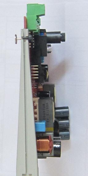
22 11) FAULT DETECTION, ELECTRONIC BOARD DETAILS AND SETTING. Each MIOL-AC beacon is power supplied with Nr.03 electronic boards, code ATB150-LXS for 230Vac or ATC150-LXS for 24Vdc (LPS components in the drawings). These boards make the LEDs flashing and they also check the lamp status. They work all together only during the day and they are divided as per below: - Electronic boards LPS-1/3/5 work only during day mode - Electronic boards LPS-2/4/6 work during day and night mode They have Nr. 08 DIP switches and the correct configuration is the following: For all LPS-1/2/3/5/6: - DIP 1 = DIP 2 = DIP 3 = DIP 5 = ON - DIP 4 = DIP 6 = DIP 7 = DIP 8 = OFF The electronic board check continuously the beacon status and in case of fault it switches on automatically the fault signalling lamps and the fault contact. The fault condition is activated even if only one of the two boards detect a fault condition. In addition: - They have a glass fuse on the input circuit - They have the input circuit electrically insulated from the output one - They have an input - They are protected against reverse connection - They are protected against LED short or open circuit Once the system detect fault condition it is possible to understand visually which is the electronic board in this condition. Please refer to the highlighted LEDs on the picture below: Page. 22 of 39 rev 2.00
23 LED1 and LED2 refer to the power supply circuit so once the system is power supplied they have to be on and fixed. Instead LED3 refers to the output so in this case we have three conditions: - Normal operation: it is on and it flashes according to the MIOL-AC lamps. The flash of all LED3 leds is synchronized. - Faulty operation: it is on and it flashes very fast, with very weak light. The flash is not synchronized with the other LED3 leds. - Third condition: it is off because it refers to an electronic board that doesn t have to work in the current mode (for example a day board during night). Once the fault condition is detected please contact our technical office by phone or for further assistance. Electronic board PSU regulatory compliance The AT-150-LXS LED DRIVER PSU, is designed to allow the Warning Beacons to comply with ICAO rules, and FAA, EASA specifications. The AT-150-LXS LED DRIVER PSU, is designed according to the directive: 2004/108/EC Electromagnetic Compatibility the conformity is given by the compliance of the following Europen Standards: EN Lighting devices, EMC immunity EN (EMC) Part 3.2 EMC limits for current <16A on each phase CEI EN limits for radioemissions on lighting 2006/95/EC Low Voltage Directive the conformity is given by the compliance of the following Europen Standards: EN Lamp Controlgear, part 1 general and safety requirements EN Lamp Controlgear, part 2-13: Particular requirements for d.c. or a.c. supplied electronic controlgear for LED modules Combustion and Energy srl, as manufacturer of AWL beacons, and relevant Driver Circuits declares to operate in accordance with EN-ISO-9001:2000 (cert nr. IQ ), and 89/392/CEE, 91/368/CEE, 93/44/CEE, 93/68/CEE directives. Combustion and Energy srl, as manufacturer of AWL beacons, and relevant Driver Circuits inform that the above part of devices can not be in service before that the full device, on which it will be incorporated, as to be declared in conformity to the rules 89/392/CEE. Page. 23 of 39 rev 2.00


24 PSU LAYOUT Page. 24 of 39 rev 2.00
25 FIXING POINT FOR RACK MODE Page. 25 of 39 rev 2.00

26 CONNECTIONS Optional Input SINCRO INPUT FAIL Page. 26 of 39 rev 2.00
27 MAIN DATA OUTPUT VOLTAGE: No Load: Max output voltage = 210 VDC With Load: Max Output working voltage = 150VDC Self Protected circuit against LED reverse polarity connection Self Protected circuit against LED short circuit Auxiliary Alarm Relay (de energized for alarm or no power) Protection Fuse (5x20; 3,15 AT) on inlet phase Synchronizations flash output available via AC Net For 115Vac application, add autotransformer input 115Vac output 230Vac (optional) - Continuous power supply V dc for max 60W (dip switch 1 & 2 must be set at 0); 200/260 Vdc for max 150W Inrush current: select D curve as for motor starter, or delayed fuse. If the AT150 electronic is powered without LEDs connected, the AT150 will enter in safe mode within 500ms; than no power will be available at LED output, even if LED are reconnected. To feed the LEDs, please disconnect power supply, wait at least 2 seconds and reconnect power supply. The AT150 has been designed to be connected to expansion card for dimmering and for communication. Page. 27 of 39 rev 2.00
28 PSU CARD Dip Switch setting Jumper Note Function 0 0 Output for MIOL-B & C 1 0 Output not to be used 0 1 Output not to be used Output for MIOL-A (multiple cards are required) 0 Automatic Syncro 1 2 External Syncro 0 Flashing light (internal or external syncro) 1 Steady burning light (bypass syncro) 0 0 Not to be used mS ramp 14 ma/ms Not to be used Not to be used 0 0 Frequency flashing 20 flash/min 1 0 Frequency flashing 40 flash/min Frequency flashing 50 flash/min Frequency flashing 60 flash/min 0 Normal functionality 1 Acquisition Aux signal during the start 1. Only for flashing selection; if steady burning set, current will be automatically reduced 2. Dip switch 7 & 8 will not be readied if external syncro is selected. 3. Not applicable for MIOL-A. if set, current will be automatically reduced Page. 28 of 39 rev 2.00
29 12) MAINTENANCE. LUXSOLAR - AERONAUTICAL LIGHTING AWL beacons maintenance has to be done in accordance with ICAO rules: Airport Service Manual Part 9 Airport Maintenance Practices 1984 par.2.6 Light Maintenance Procedure Maintenance procedure can be resumed as follow: 1) AWL beacons cleaning intervention: Dust and sand brought by wind to the beacons, often reduce the intensity of the light so they have to be removed. The same thing has to be done for water left on the glass by bugs. For this reason every two months it is necessary to clean the Beacons glass, with water and suitable fluids. Pay attention!! Do not use corrosive or oily products. If there will be meteorological phenomenon with dust, the beacons cleaning is required. 2) Damaged beacon replacement As soon as the broken beacon is detected, replace it immediately with a new one. Do not try to repair it on quote; test and repair the beacons only in laboratory. 3) Periodic check Climatic conditions, lens degrade and the reduction of the intensity emitted from light source are the causes of possible reduction of the intensity of AWL beacons. ICAO rules provide that if the light intensity is reduced under the 50% of the specified value, it is necessary the replacement of the beacon. By the way it is strongly prompted to replace the beacon if the light intensity is less than 70%. A simple light sensor, used overnight, can indicate the light intensity value, that has to be compared with the ICAO one. The optimum working period of AWL beacons (LED type) can be define in 5 years before beacons replacement. Page. 29 of 39 rev 2.00
30 MAINTENANCE MODULE Please send us this report every six months, starting from bill of materials date, at Luxsolar by fax nr Others way of sending will not be considered. The compilation of this module is necessary for the warranty. Date of document: Person in charge: Company: Report number:././ Device State of functioning and preservation Very good Good Damaged Notes MIOL-AC LED beacons MIOL-C LED beacons Control panels Internal wiring Twilight sensor Interconnection cables Page. 30 of 39 rev 2.00
31 13) TROUBLESHOOTING. LUXSOLAR - AERONAUTICAL LIGHTING Very important! Some of the tests below have to be done with live system. For this reason they should only be undertaken by qualified, experienced personnel, familiar with the equipment involved. Preliminary tests to be done without power supply: - Verify the interconnection cables installation (correct pins, bolts tighten etc.) - Verify that all green connectors on all electrical devices inside the panel are fixed correctly to the related electronic boards - Verify that all the fuses integrity - Verify that all the automatic switches are in ON position - Verify that the system receive 230Vac power supply (or 24Vdc as option) - Verify if black burnt mark are present on electrical components Please find here below some fault conditions, with dedicated solution. All the operations that require repolacement of components have to be done without power supply. - Fault = all MIOL-AC beacons are off Probable causes = there is no electrical power supply to the system, automatic switches into off position, main switch into 0 position, fused terminals open Solutions = give power supply to the system, turn automatic switches into on position, turn main switch into 1 position, close fused terminals - Fault = all MIOL-AC beacons do not flash Probable causes = there is no electrical power supply to the system, synch unit in fault Solutions = give power supply to the system, replace the synch unit - Fault = one MIOL-AC or MIOL-C beacon is in fault condition Probable causes = there is no electrical power supply to the lamp, one or more electronic board are in fault, damaged LEDs inside the beacon, wrong interconnection Solutions = give power supply to the lamp, replace the electronic board, replace the beacon, change the interconnection Page. 31 of 39 rev 2.00
32 14) MIOL-AC TESTS: ICAO CERTIFICATION, IP65 TEST, VIBRATION TEST, CLIMATIC TEST REPORT ICAO CERTIFICATION Page. 32 of 39 rev 2.00
33 Full report is available under request Page. 33 of 39 rev 2.00
34 IP65 TEST REPORT Page. 34 of 39 rev 2.00
35 Full report is available under request VIBRATION TEST REPORT Page. 35 of 39 rev 2.00

36 Page. 36 of 39 rev 2.00
37 Page. 37 of 39 rev 2.00
38 Full report is available under request Page. 38 of 39 rev 2.00
39 15) WARRANTY. LUXSOLAR - AERONAUTICAL LIGHTING LUXSOLAR Warranty, Obstruction Lighting C&E srl Luxsolar warrants the purchaser and the final user of AWL LED beacons Luxsolar that at the moment of their purchase the products were exempt of shortages and conform with ICAO Annex 14 requirements. 3 years warranty for materials and labor For a period of five years from the purchase date, Luxsolar, at its unchallengeable opinion, provides to repair or replace lacking product, directly or through other companies and people. Warranty is applicable only in case of factory default or assembly default. 3 years warranty for light degradation For a period of five years from installation date, Luxsolar at its unchallengeable opinion, provides to repair or replace (directly or through other companies and people) the product having a light intensity 7% lower than the intensity required according to ICAO Annex 14 June 2004 rules. Warranty does not cover: (1) advice or information complementary given by Luxsolar, (2) assembly and disassembly of products, (3) Fault or lacks caused by accidents, modifications, wrong use, environment temperature >55 C, voltage value higher than the indicated one, wrong maintenance, abuse, wrong installation and wrong storage. Warranty conditions: (1)The user has to communicate and detail the shortage or the reduction of light intensity before the end of the warranty period; (2) Ship the product with a copy of the purchase order and the name of the original purchaser; (3) The user has to pre-pay all shipping costs (including insurance), from plant to Luxsolar and from Luxsolar to plant for repaired and/or replaced parts; (4) Luxsolar is authorized to detain repaired/replaced parts; (5) every six months, starting bill of material s date, User has to send the maintenance module -entirely compiled- to Luxsolar service center, exclusively by FAX (no ). If this module will not be sent, warranty will not be applied to repair/replacement. Warranty limitations: this warranty will not cover other suppliers products. All the replaced/repaired products will be covered by warranty only for the remaining warranty period. The replaced products will not be necessarily identical to original ones, though having the same functionality. Repairs, replacements or compensations are the only remedies agreed by this warranty. Luxsolar declines any other kind of warranty, included, without limitations, the implicit warranty of commercial use and suitability for other uses. Damage limitations: Under no circumstances LUXSOLAR will be liable for incidental or accidental damages and loss of profits or savings - suffered by purchaser or third part - that may be caused by its products or by failure of its products. This limitation will be effective even if damage and loss have been caused by Luxsolar or its representative s negligence and even if Luxsolar is informed about the possibility of such damages and losses. This limitation of liability may not apply to damages relating to personal injury or death in jurisdictions where such damages may not be disclaimed as a matter of law. To obtain warranty service, user has to ask (by fax ) and obtain the authorization return number of material (ARM) from Luxsolar Service Centre. Page. 39 of 39 rev 2.00
AWL AIRCRAFT WARNING LIGHT LIOL-B TYPE OPERATION AND MAINTENANCE MANUAL
 AWL AIRCRAFT WARNING LIGHT LIOL-B TYPE OPERATION AND MAINTENANCE MANUAL Page. 1 of 30 rev 2.00 INDEX: 1. LIOL-B Datasheet, ordering code, weight and dimensions 2. Overview 3. ICAO rules general concepts,
Troubleshooting Guide For FG3000 Dual Medium Intensity Lighting System
 Troubleshooting Guide For FG3000 Dual Medium Intensity Lighting System TABLE OF CONTENTS SECTION 1.0 - GENERAL INFORMATION...1 1.1 Scope...1 1.2 General Description...1 1.3 Safety Precautions...2 1.4 Honeywell
ICARO Aircraft Warning Lights
 ICARO Aircraft Warning Lights INDEX INTRODUCTION... 2 PRODUCTS AWL 810/AB... 4 AWL 810/AB TWIN... 5 AWL 864/BC... 6 AWL 864/BC TWIN... 7 AWL 865.866/A... 8 AWL 864+865.866/BC+A... 9 AWL 856.857/AB... 10
LM40 Medium Intensity Aviation Obstruction Light
 Products description and applicaiton LM40 Series type A aviation obstruction lights with ICAO certificate. Type A aviation obstruction light play a warning role in tall buildings to reduce aviation hazards,daytime
ICARO. Aircraft Warning Lights GENERAL CATALOGUE
 ICARO Aircraft Warning Lights GENERAL CATALOGUE ICARO Aircraft Warning Lights INDEX INTRODUCTION... 2 WARNING LIGHTS AWL 810/AB... 4 AWL 810/AB TWIN... 5 WARNING LIGHTS AWL 864/BC... 6 AWL 864/BC TWIN...
KM300 Carbon Monoxide Detection System Installation Manual
 GE Security KM300 Carbon Monoxide Detection System Installation Manual P/N 1068922 REV 2.0 16SEP09 Copyright Copyright 2009 GE Security, Inc. All rights reserved. This document may not be copied in whole
ICARO. Aircraft Warning Lights GENERAL CATALOGUE.
 Aircraft Warning Lights is Sirena s range of high-end Aircraft Warning Lights engineered to last and perform icaro@sirena.it www.icaroawl.com MADE IN ITALY Engineered, Developed and Assembled in Rosta,
SCHMIDT LED Measured Value Display MD Instructions for Use
 SCHMIDT LED Measured Value Display MD 10.010 Instructions for Use Table of Contents 1 Important Information... 3 2 Application range... 4 3 Mounting instructions... 4 4 Electrical connection... 6 5 Signalizations...
THE EVOLUTION OF CONTROL APP & CLOUD PORTAL
 THE EVOLUTION OF CONTROL APP & CLOUD PORTAL APP MAIN APP FUNCTIONS EMERGENCY Facilitates the work of installers and company maintenance operators. Allows control of the functions of all lights of the system.
FlashGuard 3000B Dual Lighting System Troubleshooting Guide
 FlashGuard 3000B Dual Lighting System Troubleshooting Guide Table of Contents Section Flashhead (Strobe) Troubleshooting Flowchart 1 Multiple Strobe Troubleshooting Flowchart 2 Sidelight Troubleshooting
AquiTron. AT-LDM Liquid Detection Module INSTALLATION INSTRUCTIONS
 AquiTron Liquid Detection Module INSTALLATION INSTRUCTIONS Please read these instructions carefully and keep them in a safe place (preferably close to the module) for future reference. These instructions
SMART EVO 2 - User Manual ELECTRICAL PANEL FOR 2 MOTORS
 SMART EVO 2 - User Manual ELECTRICAL PANEL FOR 2 MOTORS CONTENTS 1. INTRODUCTION... 5 2. WARNINGS... 6 3. GENERAL DESCRIPTION... 7 4. INSTALLATION... 8 5. LUMINOUS INDICATORS AND COMMANDS... 9 6. DIP-SWITCH
FEC403EN Installation Manual
 FEC403EN Installation Manual P/N 10-4101-501-2FC1-01 ISS 22JAN15 Copyright Trademarks and patents Manufacturer 2015 UTC Fire & Security. All rights reserved. The FEC403EN name and logo are trademarks of
Obelux MI-2KR-A Page 1/5 ICAO Medium Intensity Type B and C, FAA L-864 and L-885, cd flashing / fixed red obstacle light
 Obelux MI-2KR-A 15.05.2014 Page 1/5 Key features Based on LED technology 2000 cd fixed / flashing red light Standalone unit with integrated power supply, fault monitoring, and day/night switch using photocell
USE AND INSTALLATION HANDBOOK
 Date : 30/10/14 Rev. 02 PR.T : FG006203 USE AND INSTALLATION HANDBOOK (SLA1) ALARM1, ALARM2 ALARM WITH BUFFER BATTERY Via Enrico Fermi, 8-35020 Polverara PD Tel.049/9772407 Fax.049/9772289 www.fourgroup.it
1. PURPOSE. This advisory circular (AC) contains the Federal Aviation Administration (FAA) specification for obstruction lighting equipment.
 contains the Federal Aviation Administration (FAA) specification for obstruction lighting equipment.") U.S. Department of Transportation Federal Aviation Administration Advisory Circular Subject: SPECIFICATION FOR OBSTRUCTION LIGHTING EQUIPMENT Date: 10/19/95 Initiated by: AAS-200 AC No:150/5345-43E Change:
U.S. Department of Transportation Federal Aviation Administration Advisory Circular Subject: SPECIFICATION FOR OBSTRUCTION LIGHTING EQUIPMENT Date: 10/19/95 Initiated by: AAS-200 AC No:150/5345-43E Change:
EXTINGUISHING AGENT RELEASE MODULE
 EXTINGUISHING AGENT RELEASE MODULE Operation, Installation & Programming Manual Revision 3.00 Distributors For: 18-20 Brookhollow Ave telephone 02 8850 2888 www.firesense.com.au Baulkham Hills NSW 2153
High-Intensity cd Aviation Light
 High-Intensity 100 000cd Page 1 5 November 30, 2016 Optical Characteristics 100 000cd Flashing @ Day 20 000cd Flashing @ Twilight 2 000cd Flashing @ Night Infrared 850nm Colour aviation WHITE Horizontal
Sentry LIQUID LEVEL CONTROLLER MODEL 120 OPERATING MANUAL.
 Sentry LIQUID LEVEL CONTROLLER MODEL 120 OPERATING MANUAL www.aquaticsentry.com TABLE OF CONTENTS 1. SAFETY PRECAUTIONS... 3 2. APPLICATION... 3 2.1 HIGH AND LOW LEVEL ALARM 2.2 PUMP DOWN CONTROLLER 2.3
Installation, Operating and Maintenance Manual
 STATUS ZONES CONTROLS FIRE FAULT DISABLED FIRE 1 2 3 4 5 6 7 8 TEST FAULT DISABLED 1 5 BUZZER SILENCE RESET 1 2 TEST 2 6 LAMP TEST 3 SUPPLY 3 7 SYSTEM FAULT 4 8 SOUNDERS ACTIVATE/ SILENCE 4 FAULTS INSTRUCTIONS
Obstruction Lighting
 Obstruction Lighting Light A Light B Light C Light D Light E Avlite Systems has an extensive range of LED obstruction lighting to clearly mark structures such as telecommunication towers, wind turbines
Remote Relay Module (RRM)
") Remote Relay Module (RRM) Instruction Manual WARNING THIS MANUAL MUST BE CAREFULLY READ BY ALL INDIVIDUALS WHO HAVE OR WILL HAVE THE RESPONSIBILITY FOR INSTALLING, USING OR SERVICING THIS PRODUCT. Like
Remote Relay Module (RRM) Instruction Manual WARNING THIS MANUAL MUST BE CAREFULLY READ BY ALL INDIVIDUALS WHO HAVE OR WILL HAVE THE RESPONSIBILITY FOR INSTALLING, USING OR SERVICING THIS PRODUCT. Like
MaxLite LED Vapor Tight Linear Fixture
 General Safety Information To reduce the risk of death, personal injury or property damage from fire, electric shock, falling parts, cuts/abrasions, and other hazards read all warnings and instructions
10810 W. LITTLE YORK RD., STE. 130 HOUSTON TX VOICE (713) FAX (713) web: IMPORTANT!!!
 FAX (713) web: IMPORTANT!!!") 10810 W. LITTLE YORK RD., STE. 130 HOUSTON TX 77041-4051 VOICE (713) 973-6905 FAX (713) 973-9352 web: www.twrlighting.com IMPORTANT!!! PLEASE TAKE THE TIME TO FILL OUT THIS FORM COMPLETELY. FILE IT IN
10810 W. LITTLE YORK RD., STE. 130 HOUSTON TX 77041-4051 VOICE (713) 973-6905 FAX (713) 973-9352 web: www.twrlighting.com IMPORTANT!!! PLEASE TAKE THE TIME TO FILL OUT THIS FORM COMPLETELY. FILE IT IN
2-Port alarmcharge Hub - Manual
 Installation Manual 1. What s in the box 2. Fixture preparation 3. Mounting 4. Mechanical 5. Device power Operation Manual 6. Device connectors and connections 7. Alarming remote control 8. Safety 9. Warranty
DESCRIPTIVE AND INSTALLATION INSTRUCTION MANUAL FOR MODEL G1000 AND H1000 SERIES ANNUNCIATORS
 DESCRIPTIVE AND INSTALLATION INSTRUCTION MANUAL FOR MODEL G1000 AND H1000 SERIES ANNUNCIATORS SEEKIRK, INC. 2420 Scioto Harper Dr. Columbus, OH 43204 Tel: (614) 278-9200 FAX: (614) 278-9257 email: seekirk@seekirk.com
USER GUIDE. DRENA 2 - User Manual ELECTRICAL PANEL FOR 2 MOTORS - WASTE WATER -
 USER GUIDE DRENA 2 - User Manual ELECTRICAL PANEL FOR 2 MOTORS - WASTE WATER - II CONTENTS 1. SYMBOLS AND WARNINGS... 5 2. GENERAL INFORMATION... 6 3. WARNINGS... 7 4. GENERAL DESCRIPTION... 8 5. INSTALLATION...
OPERATION AND INSTALLATION MANUAL
 OPERATION AND INSTALLATION MANUAL Manufactured & Serviced By: SunPumps, Inc. 325. Main St. Safford, AZ 85546 /M* gf& (928) 348-9652 Made in America 1.0 Introduction Thank you for selecting a SunPumps SP
3. Intended use. 4. Function. 1. Product characteristics. 2. Safety. Functional description. Channel A light. Motion detector
 EN Motion detector themova S360-101 DE WH 1030565 themova S360-101 DE GR 1030566 themova S360-101 AP WH 1030555 themova S360-101 AP GR 1030556 1. Product characteristics 307067 Passive infra-red motion
MANUAL Overflow sensor NVF-104/34-PF
 PROCESS AUTOMATION MANUAL Overflow sensor NVF-104/34-PF ISO9001 0102 Overflow sensor NVF-104/34-PF With regard to the supply of products, the current issue of the following document is applicable: The
USE AND INSTALLATION HANDBOOK
 Date : 10/02/14 Rev. 01 PR.T : FG006176 USE AND INSTALLATION HANDBOOK SIMPLEX-UP CONTROL PANEL FOR 1 ELECTRIC PUMP WITH CURRENT CONTROL. SIMPLEX-UP Via Enrico Fermi, 8-35020 Polverara PD Tel.049/9772407
RE-PR3-E-27 3-Phase Panel Mount 27kW
 Page 1 of 6 RE-PR3-E-27 3-Phase Panel Mount 27kW Features: Benefits: 0-10Vdc, 0-5Vdc, 4-20mA or manual via potentiometer control input Over temperature protection with auto reset Enclosed panel mounting
RED1. Technical Support And Installation Manual. Models ST, E1, E2, E3, E4, and 420. Approved
 RED1 Models ST, E1, E2, E3, E4, and 420 Technical Support And Installation Manual 210111 FM Approved 1. OVERVIEW 1 2. BASIC OPERATION 3 2.1 General 3 2.2 Field-of-View 4 2.3 Range 4 2.4 Environment 4 2.5
LED VISOR LIGHT INSTALLATION & OPERATION MANUAL IMPORTANT: Contents:
 INSTALLATION & OPERATION MANUAL LED VISOR LIGHT Contents: IMPORTANT: Introduction...2 Features and Specifications...2-3 Installation...3 Synchronization...4 Setting the Flash Pattern...4 Maintenance...4
The New EMC Directive 2004/108/EC
 The New EMC Directive 2004/108/EC In the process of the review I have tried to spell out in words what is often referred to as a section number. This helps reduce the need to flip pages as one reads this.
FEC400 Series. Installation Manual
 FEC400 Series Conventional microprocessor controlled fire detection and alarm panels with extinguishing control Installation Manual Version 2.3 / August 2004 Aritech is a GE Interlogix brand. http://www.geindustrial.com/ge-interlogix/emea
WIO200 Water in oil sensor
 WIO200 Water in oil sensor User manual Rev. 1.15 Dato: 2011-11-03 Page 1 of 24 TABLE OF CONTENTS Table of contents... 2 Introduction... 3 Safety Advice... 4 Function... 6 Normal operation... 7 Failure
Original instructions INCA-1 Emergency stop for enclosure installation INCA-1S Safety stop for enclosure installation
 Original instructions INCA-1 Emergency stop for enclosure installation INCA-1S Safety stop for enclosure installation ABB AB / Jokab Safety Varlabergsvägen 11, SE-434 39 Kungsbacka, Sweden www.abb.com/lowvoltage
DESCRIPTIVE AND INSTALLATION INSTRUCTION MANUAL FOR MODEL AH1000, BH1000, AND EH1000 SERIES ANNUNCIATORS
 DESCRIPTIVE AND INSTALLATION INSTRUCTION MANUAL FOR MODEL AH1000, BH1000, AND EH1000 SERIES ANNUNCIATORS SEEKIRK, INC. 2420 Scioto Harper Dr. Columbus, OH 43204 Tel: (614) 278-9200 FAX: (614) 278-9257
OWNERS MANUAL MODEL 451 (-101 & -201)
") OWNERS MANUAL MODEL 451 (-101 & -201) Guardian Avionics CO Guardian, LLC. 1951 E Airport Drive Tucson, AZ 85756 Phone: 520-889-1177 8:00 am - 5:00 pm MST support@guardianavionics.com 2 Table of Contents
OWNERS MANUAL MODEL 451 (-101 & -201) Guardian Avionics CO Guardian, LLC. 1951 E Airport Drive Tucson, AZ 85756 Phone: 520-889-1177 8:00 am - 5:00 pm MST support@guardianavionics.com 2 Table of Contents
Snifter ATEX22 VERSION. User Manual. Distributor
 Snifter ATEX22 VERSION User Manual Distributor Version 1.4 09/09/2009 Table of Contents 1. INTRODUCTION... 3 1.1. Safety... 3 1.2. Product overview... 4 1.3. How does it work?... 4 2. INSTALLATION... 5
MODEL RLY-DIM-D INSTALLATION INSTRUCTIONS
 MODEL RLY-DIM-D INSTALLATION INSTRUCTIONS IMPORTANT SAFEFGUARDS WHEN USING ELECTRICAL EQUIPMENT, BASIC SAFETY PRECAUTIONS SHOULD ALWAYS BE FOLLOWED. THESE INCLUDE: READ AND FOLLOW ALL SAFETY INSTRUCTIONS
Training Guide For FG3000 Dual Medium Intensity Lighting System
 Training Guide For FG3000 Dual Medium Intensity Lighting System Manual No. MPR-00000009-001 Honeywell Airport Systems 2162 Union Pl. Simi Valley, CA 93065 Phone: (805) 581-5591 Fax: (805) 581-5032 http://www.oblighting.com
Instructions for the fan motor control system with integrated wiring terminals SILVER C
 Instructions for the fan motor control system with integrated wiring terminals SILVER C 1. General The motor control system is used for controlling the type EC, 0.41-10 kw fan motors in the SILVER C units.
JBE LED2000 INDUSTRIAL SOLUTIONS FOR LED & INCANDESCENT MAINS LIGHTING FLICKER FREE TRAILING EDGE DIMMER
 JBE LED2000 INDUSTRIAL SOLUTIONS FOR LED & INCANDESCENT MAINS LIGHTING FLICKER FREE TRAILING EDGE DIMMER JBE LED Dimming Controller for 110V* & 220V/ 240V AC LED Systems Thank you for purchasing high quality
SERIES VAC Microprocessor-Based Direct Spark Ignition Control FEATURES APPLICATIONS SPECIFICATIONS DESCRIPTION. Export Information (USA)
") R SERIES 35-70 120 VAC Microprocessor-Based Direct Spark Ignition Control F-35-70 November 2015 FEATURES Safe start with DETECT-A-FLAME flame sensing technology Custom pre-purge and inter-purge timings
R SERIES 35-70 120 VAC Microprocessor-Based Direct Spark Ignition Control F-35-70 November 2015 FEATURES Safe start with DETECT-A-FLAME flame sensing technology Custom pre-purge and inter-purge timings
Rectifier RC-series. Manual RC-series English MA doc. Manual Wall and 19 English
 Rectifier RC-series Manual RC-series English Manual Wall and 19 English Presentation The RC-series is a rectifier for either directly powering the load or for use together with batteries. It is designed
18W Round LED Wall/Ceiling Light with Microwave Sensor
 18W Round LED Wall/Ceiling Light with Microwave Sensor Model: LEDMR18WHMS Installation & Operating Instructions 1 1. General Information These instructions should be read carefully and retained for further
Refrigerated Incubator Model and Operating Instructions
 Refrigerated Incubator Model 165000 and 165000-2 Operating Instructions N2400379 - Rev. 1 08May2018 1 Contents 1. SAFETY...3 1.1. EMF INTERFERENCE...4 1. PRODUCT INFORMATION...5 1.1 INTRODUCTION...5 2.
4 & 8-POINT ANNUNCIATORS Instruction Manual
 4 & 8-POINT ANNUNCIATORS Instruction Manual 8 Field Selectable Sequences All Common ISA Sequences 4 or 8-Point (Channel) Monitoring Free Replaceable Message Labels Type 4X, NEMA 4X, IP65 Front Universal
12W Round LED Wall/Ceiling Light with Microwave Sensor
 12W Round LED Wall/Ceiling Light with Microwave Sensor Model: LEDSR12WHMS Installation & Operating Instructions 1 1. General Information These instructions should be read carefully and retained for further
Matrix2000. User Guide - CPD Advanced Analog Fire Alarm Control Panel 4 24 Zones. Version: 2.0 Revision: 1
 Matrix2000 User Guide - CPD Advanced Analog Fire Alarm Control Panel 4 24 s Version: 2.0 Revision: 1 IMPORTANT INFORMATION Limitation of liability It is mandatory, Matrix2000 panel to be installed in accordance
Design Manual Installation Operation Maintenance
 Design Manual Installation Operation Maintenance Model FT194 UV/IR Portable Flame Detector Test Lamp 23282 Mill Creek Drive, Suite 215 Laguna Hills, CA 92653 USA +1.949.583.1857 Phone +1.949.340.3343 Fax
Operating Guide Safe Torque Off
 ENGINEERING TOMORROW Operating Guide Safe Torque Off VLT Frequency Converters vlt-drives.danfoss.com Contents Operating Guide Contents 1 Introduction 2 1.1 Purpose of the Manual 2 1.2 Additional Resources
KFP-CF Series Operation Manual
 KFP-CF Series Operation Manual P/N 501-415103-2-31 REV 03.10 ISS 13NOV13 Copyright Trademarks and patents Manufacturer Version Certification European Union directives Contact information 2013 UTC Fire
REA 105 Arc Protection Module. Operator s Manual
 REA 105 1MRS 751005-MUM Issued: 20.04.1998 Version: B2/26.5.2000 Checked: Approved: REA 105 We reserve the right to change data without prior notice. Contents: 1. General...4 1.1. Features...4 2. Safety...5
USER MANUAL MODEL READ ALL INSTRUCTIONS BEFORE PROCEEDING. 5-2 Day Programmable Multi-Stage 2 Heat/1 Cool Heat Pump Digital Thermostat
 WARNING! Important Safety Information Builder MODEL 2200 Series 5-2 Day Programmable Multi-Stage 2 Heat/1 Cool Heat Pump Digital Thermostat USER MANUAL Compatible with low voltage multi stage heat/cool
PRESSURE WASHER MODEL NO: JETSTAR 1750 OPERATION & MAINTENANCE INSTRUCTIONS. WARNING Read the instructions before using the machine PART NO:
 WARNING Read the instructions before using the machine PRESSURE WASHER MODEL NO: JETSTAR 1750 PART NO: 7333230 OPERATION & MAINTENANCE INSTRUCTIONS LS0711 INTRODUCTION Thank you for purchasing this CLARKE
Original instructions Sense7-series Non-contact coded safety switch
 Original instructions Sense7-series Non-contact coded safety switch ABB AB / Jokab Safety Varlabergsvägen 11, SE-434 39 Kungsbacka, Sweden www.abb.com/lowvoltage Read and understand this document Please
52 STRATHMERE CEILING FAN
 52 STRATHMERE CEILING FAN Owner s Manual Models #20341 If a problem cannot be remedied or you are experiencing difficulty with installation, please contact the Service Department: 1-877-459-3267, 9 a.m.-
1. Product characteristics 4 2. Safety 5 3. Proper use 5 4. Operation 6
 307214 1103107701 EN Presence detector theronda S360-101 DE WH 2080565 theronda S360-101 DE GR 2080566 theronda S360-101 AP WH 2080555 theronda S360-101 AP GR 2080556 1. Product characteristics 4 2. Safety
WLS-T25 Solar Powered Low Intensity Duty & Stand-by Aviation Obstruction Light
 Duty & Stand-by Aviation Obstruction Light Instruction Manual Rev: 1.0V Descriptions This product is a low intensity aviation obstruction light, suitable to be used in the places without electricity power,
Operating Instructions. For. Alarm Control Module. Model SSR 500
 SSR 500 LEVEL CONTROL RELAY MODULE Operating Instructions For Alarm Control Module Model SSR 500 SSR Operation Instructions Rev. 1 Jan 01 Page 1/7 1. Note Please read and take note of these operating instructions
Installing the Cisco ONS FAP-4 Fuse Alarm Panel
 Installing the Cisco ONS 15454-FAP-4 Fuse Alarm Panel Product Number: 15454-FAP-4= This document explains how to install, test, operate, and maintain the Cisco ONS 15454-FAP-4 fuse alarm panel. This document
Installation, Operation & Service Manual
 Installation, Operation & Service Manual WARNING Improper installation, adjustment, alteration, service or maintenance can result in death, injury or property damage. Read the Installation, Operation and
HUGHEY & PHILLIPS, LLC.
 HUGHEY & PHILLIPS, LLC. Installation and Operation Guide HORIZON MEDIUM INTENSITY DUAL LED LIGHTING SYSTEM CONTROLLER FAA TYPES A1, D1, & E1 MANUAL EPM-00000044-001 Revision F Hughey & Phillips, LLC. 240
CO Guardian LLC Document No E. AIRPORT DRIVE Date: TUCSON, AZ CO Guardian LLC 1951 E. Airport Dr.
 1951 E. AIRPORT DRIVE Date: 8-20-2004 CO Guardian LLC 1951 E. Airport Dr. Tucson, AZ 85706 OWNERS MANUAL CARBON MONOXIDE DETECTOR MODEL 452-201 REMOTE UNIT MODEL 452-201 OWNERS MANUAL Page 1 of 22 INTENTIONALLY
Ion Endeavor Pump Controller Digital Level Control with Pump Alternation and High Water Alarm
 Ion Endeavor Controller Digital Level Control with Alternation Page 1 of 8 General Overview The Ion Endeavor is a pump controller that senses a water level of up to 72", has a configurable water level/pump
IMPORTANT SAFEGUARDS READ AND FOLLOW ALL SAFETY INSTRUCTIONS. HZM-Series-Class I, Div 2 Battery Unit. Instalation instructions
 HZM-Series-Class I, Div 2 Battery Unit HZM-Series-Class I, Div 2 Battery Unit Instalation instructions IMPORTANT SAFEGUARDS 1 4 5 6 7 13 When using electrical equipment, basic safety precautions should
Vigilant LED Based Obstruction Lights
 Vigilant LED Based Obstruction Lights Index 02 Vigilant LED Based L-856 High Intensity (White) Strobe 03 Vigilant LED Based L-856 / L-864 High Intensity (White/Red) Strobe 04 Vigilant LED Based L-865/L-864
Instructions for the heat exchanger control system SILVER C RX, RECOnomic, sizes 100/120, RECOsorptic, sizes
 Instructions for the heat exchanger control system SILVER C RX, RECOnomic, sizes 100/120, RECOsorptic, sizes 50-120 1 General The heat exchanger control system is a control system for 380 W step motors
SERIES VAC Microprocessor-Based Hot Surface Ignition Control FEATURES APPLICATIONS SPECIFICATIONS DESCRIPTION AGENCY CERTIFICATIONS
 SERIES 35-65 24 VAC Microprocessor-Based Hot Surface Ignition Control F-35-65 August 2015 FEATURES Safe start with DETECT-A-FLAME flame sensing technology Custom pre-purge and inter-purge timings* 120/240
ESP TECHNOLOGIES LIMITED
 Alarm Technology ESPAN-01 Series Annunciator System Combination type User Manual (Rev. 1) ESP TECHNOLOGIES LIMITED www.esptechno.com Content Page Introduction 2 General Description 2 Overview - Annunciator
MODEL LP3 INSTALLATION AND SERVICE INSTRUCTIONS FOR STREAMLINE LP3 STROBE LIGHTS
 Specifications subject to change without notice. USA 150303 Page 1 of 10 MODEL LP3 INSTALLATION AND SERVICE INSTRUCTIONS FOR STREAMLINE LP3 STROBE LIGHTS Specifications subject to change without notice.
WARNING Important Safety Information
 1 Specifications Premier Series Non-Programmable Thermostats MODEL 3000 MODEL 3200 1 2 3 4 5 Specifications Installation Testing Your New Thermostat Programming User Settings Temperature Adjustment WARNING
Ion Genesis II Pump Controller Digital Level Control with Pump Alternation and High Water Alarm
 Page 1 of 8 General Overview Thank you for purchasing an Ion Genesis controller. Take the time to read the instructions carefully before using this appliance. We strongly recommend that you keep this instruction
DRYTEK 1 - User Manual ELECTRICAL PANEL FOR 1 MOTOR WITH POWER FACTOR CONTROL
 DRYTEK 1 - User Manual ELECTRICAL PANEL FOR 1 MOTOR WITH POWER FACTOR CONTROL CONTENTS 1. INTRODUCTION... 5 2. WARNINGS... 6 3. GENERAL DESCRIPTION... 7 4. INSTALLATION... 8 5. CONTROL PANEL... 9 5.1
FAA RECOMMENDATIONS Marking & Visual Identification of Obstacles
 REFERENCE GUIDE FAA RECOMMENDATIONS Marking & Visual Identification of Obstacles Avlite Systems an international designer & manufacturer of complete aviation lighting systems; airfield, heli & obstruction
INSTRUCTION MANUAL T119 1MN0110 REV. 0. operates with ISO9001 certified quality system
 INSTRUCTION MANUAL 1MN0110 REV. 0 operates with ISO9001 certified quality system TECSYSTEM S.r.l. 20094 Corsico (MI) Tel.: +39-024581861 Fax: +39-0248600783 http://www.tecsystem.it R. 1.1 25/08/16 ENGLISH
PD154 & PD158 VIGILANTE II ANNUNCIATORS Instruction Manual
 PD154 & PD158 VIGILANTE II ANNUNCIATORS 8 Field Selectable Sequences All Common ISA Sequences 4 or 8-Point (Channel) Monitoring Free Replaceable Message Labels Type 4X, NEMA 4X, IP65 Front Universal Power
CO Guardian LLC Document: E. AIRPORT DRIVE Date: 11/15/05 OWNERS MANUAL
 OWNERS MANUAL CARBON MONOXIDE DETECTOR MODELS Panel mount and Remote Detectors (R) (353 and 353R) 353 FAMILY MODEL OWNERS/INSTALLATION MANUAL Page 1 of 22 LOG OF REVISIONS REV NO. PAGE NO. DATE DESCRIPTION
Vigilant LED Based Obstruction Lights
 Vigilant LED Based Obstruction Lights Index 02 Vigilant LED Based L-865 High Intensity (White) Strobe 03 Vigilant LED Based L-856/L- 864 High Intensity (White/Red) Strobe 04 Vigilant LED Based L-864/L-865
Lodam Compressor Protection Module. Technical manual. Version 3.0 SE-G1
 Lodam Compressor Protection Module Technical manual Version 3.0 SE-G1 Contents 1. Read this first... 4 1.1. Reading instructions... 4 1.2. User manual... 4 1.3. Safety... 4 2. General... 5 3. Definitions...
MICROtrac MICROPROCESSOR BASED WATER TREATMENT CONTROLLER. Installation and Operation Manual REV. L
 MICROtrac MICROPROCESSOR BASED WATER TREATMENT CONTROLLER Installation and Operation Manual MICROtrac Warranty Pulsafeeder, Inc. warrants MICROtrac control systems (including the conductivity sensor) of
LED CEILING LIGHT WITH MOTION SENSOR AND REMOTE. ITM. / ART Model: LM56123 CARE & USE INSTRUCTIONS
 LED CEILING LIGHT WITH MOTION SENSOR AND REMOTE ITM. / ART. 1165831 Model: LM56123 CARE & USE INSTRUCTIONS IMPORTANT, RETAIN FOR FUTURE REFERENCE: READ CAREFULLY For assistance with assembly or installation,
Power Supply Display Module PSDM. Installation and Operation Manual
 Power Supply Display Module PSDM Installation and Operation Manual Read this manual before using this product. Failure to follow the instructions and safety precautions in this manual can result in serious
Date: DRAFT Initiated by: AAS-100
 U.S. Department of Transportation Federal Aviation Administration Advisory Circular Subject: SPECIFICATION FOR OBSTRUCTION LIGHTING EQUIPMENT Date: DRAFT Initiated by: AAS-100 AC No.: 150/5345-43H Change:
NIR O P E R A T I N G I N S T R U C T I O N S RETROREFLECTIVE PHOTOEYE U L M O N I T O R E D DEVICE
 O P E R A T I N G I N S T R U C T I O N S NIR-50-325 RETROREFLECTIVE PHOTOEYE U L 3 2 5-2 0 1 8 M O N I T O R E D DEVICE 4564 Johnston Parkway, Cleveland, Ohio 44128 P. 800 426 9912 F. 216 518 9884 Sales
SensaGuard TM Integrated Latch Installation Instructions
 TM Integrated Latch Installation Instructions Certifications IMPORTANT: SAVE THESE INSTRUCTIONS FOR FUTURE USE Note: Refer to Technical Specifications for Certification information and ratings. 2 TM Installation
Operations Manual. Motion Detector Module Model ZS10
 Motion Detector Module Model ZS10 The must be referred to for correct installation. Failure to comply with the shall void all warranties and liabilities. Overview The ZS10 Motion Detector Module is an
HOKKIM INTEGRATED AMF CONTROL BOARD MANUAL FOR MODELS: HAMF-8 AND HAMF-4
 HOKKIM INTEGRATED AMF CONTROL BOARD MANUAL FOR MODELS: HAMF-8 AND HAMF-4 INTRODUCTION Thank you for purchasing the Hokkim Integrated Automatic Mains Failure Control Board model HAMF- 8 or HAMF-4. We shall
Miniature Thermoelectric Cooler Controller MTCC-01 user's guide
 Miniature Thermoelectric Cooler Controller MTCC-01 user's guide 1 Table of Contents 1. Warranty... 3 2. MTCC-01-xxx overview... 4 2.1. MTCC-01-xxx specification... 4 2.2. TE cooled detector temperature
TX7130. Conventional Reflective Beam Detector Installation and Operation Manual. TANDA UK Technology Copyright 2015, All right reserved.
 TX7130 Conventional Reflective Beam Detector Installation and Operation Manual Technology Copyright 2015, All right reserved. Product Safety To prevent severe injury and loss of life or property, read
Non-Contact Safety Switches FF6 Series Issue 4. Sensing and Internet of Things. Datasheet FEATURES DESCRIPTION DIFFERENTIATION
 Sensing and Internet of Things Non-Contact Switches FF6 Series DESCRIPTION Honeywell FF6 Series are magnetically actuated noncontact safety limit switches for use in machine guarding applications, designed
CLIMAGUARD Air-to-Air Outdoor Heat Exchangers INSTRUCTION MANUAL. Rev. H 2015 Pentair Equipment Protection P/N
 CLIMAGUARD Air-to-Air Outdoor Heat Exchangers TX23, TX33, TX38, TX52 Model INSTRUCTION MANUAL Rev. H 2015 Pentair Equipment Protection P/N 10-1008-221 87976519 TABLE OF CONTENTS RECEIVING THE HEAT EXCHANGER...3
MaxLite LED Round Pendant Highbay Series
 General Safety Information To reduce the risk of death, personal injury or property damage from fire, electric shock, falling parts, cuts/abrasions, and other hazards read all warnings and instructions
Syncro Matrix Analogue Addressable Fire Alarm Mimic Panel Product Manual
 Syncro Matrix Analogue Addressable Fire Alarm Mimic Panel Product Manual Australia Issue 01 April 2012 Contents 1 Introduction 3 2 Safety 3 3 Installation 4 3.1 Mounting the Cabinet 4 4 Specifications
IMPORTANT SAFEGUARDS READ AND FOLLOW ALL SAFETY INSTRUCTIONS. 3LERHZ Series Class I, Div 2 Combo Unit. Installation instructions
 3LERHZ Series Class I, Div 2 Combo Unit Installation instructions 3LERHZ Series Class I, Div 2 Combo Unit IMPORTANT SAFEGUARDS 1 3 When using electrical equipment, basic safety precautions should always
Model Gas Alarm Panel APPLICABILITY & EFFECTIVITY. This manual provides instructions for the following Sierra Monitor products:
 Model 2102 Gas Alarm Panel APPLICABILITY & EFFECTIVITY This manual provides instructions for the following Sierra Monitor products: Model Description 2102-00 Alarm Panel 2 Channel 2102-01 Alarm Panel 2
INSTALLATION AND OPERATING INSTRUCTIONS FOR THE VEHICLE-MOUNTED RADIATION DETECTION SYSTEM
 INSTALLATION AND OPERATING INSTRUCTIONS FOR THE VEHICLE-MOUNTED RADIATION DETECTION SYSTEM D-tect Systems 11814 South Election Road, Suite 200 Draper, UT 84020 www.dtectsystems.com 1 Introduction The mini