REA 105 Arc Protection Module. Operator s Manual
|
|
|
- Cameron Lyons
- 6 years ago
- Views:
Transcription
1 REA 105
2
3 1MRS MUM Issued: Version: B2/ Checked: Approved: REA 105 We reserve the right to change data without prior notice. Contents: 1. General Features Safety Block diagram Operation description Light detection Trip output Operation of IN1 and OUT1 ports Operation of port IN Circuit-breaker failure protection Self-supervision unit (IRF) Front panel Functions of LEDs and switches Connections Commissioning Instructions for commissioning: Testing of arc protection system level Light reference setting Dimensions and fixing Technical data Order information Extension unit Pre-manufactured sensor fibres Accessories for manufacturing sensor fibres Connection cables References Index...20 ABB Automation 3
4 REA 105 1MRS MUM 1. General The REA 105 is an extension unit designed to be used together with the arc protection relay REA 101. The function of the unit is to detect light and to carry out tripping, if the REA 101 unit provides an overcurrent signal at the same time, or delivers a trip command. The use of extension units allows the protection area to be extended and the protected object to be divided into smaller areas. Thus a more selectove system is obtained Features Loop-type or radial sensor fibre for arc detection. 2 high-speed semi-conductor outputs for tripping. Signal relay activated by light detected by the sensor fibre. 3 RJ45 ports for the connection of REA 101 relay and extension units. Circuit-breaker failure protection. Delayed light signal to REA 101, which opens the higher-level circuit breaker. Self-supervision unit monitoring operating voltages and the sensor fibre loop. 4 ABB Automation
5 1MRS MUM REA Safety! National and local electrical safety regulations must always be followed. Dangerous voltages can occur on the connectors, even though the auxiliary voltage is disconnected. The frame of the units has to be carefully earthed. Only a competent electrician is allowed to carry out the electrical installation. Sensor fibres have to be handled according to the instructions given by the sensor fibre manufacturer. Settings and configuration changes have to be done with the auxiliary supply voltage (U aux ) disconnected. Malfunction may occur if changes are made with the supply voltage connected. ABB Automation 5
6 REA 105 1MRS MUM 3. Block diagram HSO2 HSO1 X IN sensor 1 OUT SG1/ 4 SG1/ 3 Light detection and testing SG1/ 8 light SG1/ 6 7 SG1/ 7 6 Circuitbreaker failure protection SG1/ 1 SG1/ 5 & PORT IN 1 PORT OUT 1 X1 X2 Cable connection block SG1/ 2 trip I> Power PORT IN 2 X3 Cable connection block I> trip loh5a )LJ 5($EORFNGLDJUDP 6 ABB Automation
7 1MRS MUM REA Operation description 4.1. Light detection The switch SG1/4 (Sensor ON/OFF) is used for selecting the sensor fibre. The light captured by the sensor fibre is amplified and compared either to an automatic or a manual reference level. Once the reference level has been exceeded, a light signal is generated and the signal relay (Light) is activated for about 0.5 seconds. In a trip situation, the central unit REA 101 or the REA 105 unit itself provides information about the tripping, and the signal relay is locked in the active state. If no tripping occurs, the relay resets. The SG1/3 switch (Automatic light ref. level ON/OFF) is used for selecting the automatic or manual reference level. The unit itself forms the automatic reference level according to the present backlight intensity measured by the sensor fibre. The potentiometer Light Ref. Level Adj. on the front panel is used for setting the manual reference level. The sensor fibre is monitored by sending a test pulse through the fibre. Unless the test pulse is received at regular time intervals at the other end of the loop, the sensor fault LED Fault and the IRF indicator LED IRF are activated. Condition monitoring of the sensor fibre can be deactivated with the switch SG1/8 (Sensor supervision deactivation ON/OFF), in which case a radial i.e. a terminating fibre can be used. When the switch SG1/5 (Light to port IN1 ON/OFF) is in the OFF position, no light signal is transmitted to the REA 101 unit located in the direction of the port IN1, and the REA 105 extension unit alone carries out tripping if the REA 101 unit delivers an overcurrent signal at the same time. When the switch SG1/5 is in the ON position, the light signal is transmitted to the central unit REA 101. Both the REA 105 and the REA 101 unit trip if the overcurrent signal is active. Delayed tripping by REA 101 is explained in Circuit-breaker failure protection. The REA 105 unit does not send a light signal to the port IN Trip output The trip output contains two high-speed, galvanically isolated IGBT semi-conductor outputs (HSO1 and HSO2). These outputs can be used in DC and AC circuits. The control signal of the outputs is activated if the unit detects light and the central unit REA 101 delivers an overcurrent signal, provided the operating voltage fault signal is inactive. Once the central unit REA 101 performs tripping, all the REA 105 extension units connected to it trip as well. When the REA 105 trips, the outputs remain in an active state. The outputs are reset by pressing the Reset push-button or via the RESET input of the central unit. ABB Automation 7
8 REA 105 1MRS MUM 4.3. Operation of IN1 and OUT1 ports 4.4. Operation of port IN2 The ports IN1 and OUT1 are connected in parallel. The connection cable from the central unit REA 101 is connected to the port IN1 and the connection cable to the next extension unit departs from the port OUT1. A maximum of five extension units, one after the other, can be linked to one port of the central unit. The terminator of the last extension unit has to be connected using the switch SG1/ 1: Terminator 1 ON/OFF. This allows the REA 101 unit to monitor the condition of the connection cable. Should the terminator be unconnected, the fault indicating LED Port A/B Fault of the central unit REA 101 and the IRF indicator LED IRF are activated, and the IRF relay resets. The REA 105 extension unit gets the operating voltage over the port IN1. Port IN2 is used when the ports of two REA 101 units are to be connected together, for instance, for the transfer of overcurrent signals. (See sections Functions of LEDs and switches and Application examples of the REA 101 Operator s manual 1MRS MUM. In this case, the ports must be terminated, that is, the terminators for both ports IN1 and IN2 have to be connected (switches SG1/1-2). The port is galvanically isolated from the rest of the device, because otherwise possible potential differences between the central units might cause problems Circuit-breaker failure protection The circuit-breaker failure protection is implemented by delaying the light signal that is transmitted to the bus via the IN1 port. The switch SG1/6 (Delayed light to port IN1 ON/OFF) is used to activate the circuitbreaker failure protection. When the circuit-breaker failure protection is in use, the switch SG1/5 (Light to port IN1 ON/OFF) has to be in the OFF position. The desired delay time, 100 ms or 150 ms, is selected with the switch SG1/7 (Delay ON = 150 ms, OFF = 100 ms). Once the REA 105 unit trips the delay time starts running. If the overcurrent signal is active when the delay time runs out, the REA 105 extension unit transfers a light signal to the port IN1 and delayed tripping will be carried out by the REA 101 unit. Should the overcurrent signal disappear during the time delay, no light signal will be transmitted by the REA 105 unit, and no delayed tripping will be performed by the REA 101 relay. 8 ABB Automation
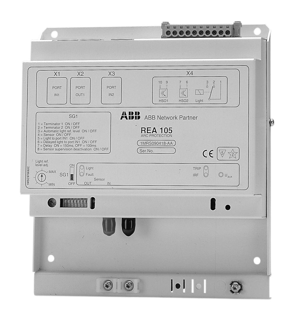
9 1MRS MUM REA Self-supervision unit (IRF) In addition to that mentioned above, the self-supervision unit monitors the operating voltages of the device. If a fault is detected in the operating voltages, the selfsupervision unit prevents the device from operating. When the LED indicator IRF of the REA 105 unit is lit, the port fault LED Port A/B Fault of the REA 101 relay starts flashing, the LED indicator IRF is activated and the IRF relay resets Front panel X1 Port IN1 X2 Port OUT1 X3 Port IN2 10 ~ + ~ ~ + ~ - X HSO1 HSO2 Light SG1 1 = Terminator 1 ON/OFF 2 = Terminator 2 ON/OFF 3 = Automatic light ref level ON/OFF 4 = Sensor ON/OFF 5 = Light to port IN1 ON/OFF 6 = Delayed light to port IN1 ON/OFF 7 = Delay ON = 150 ms, OFF = 100 ms 8 = Sensor supervision deactivation ON/OFF ABB Network Partner REA 105 ARC PROTECTION 1MRS AA Ser. No 5 2 Light ref. level adj. ON MAX SG1 MIN OFF Light Fault Sensor OUT IN TRIP IRF Uaux paneli5 )LJ )URQWSDQHO ABB Automation 9
10 REA 105 1MRS MUM 4.8. Functions of LEDs and switches LEDs activated: U aux Light TRIP IRF Fault + IRF Power supply is connected The sensor fibre has detected light The unit has tripped The self-supervision system has detected a fault (The fault LED Port A/B Fault of the REA 101 relay is flashing, the IRF indicator is lit, and the IRF relay has reset) Sensor fibre broken (The sensor fibre may still detect light between the sensor input and the breakage) Transmitter/transceiver is defective Light Ref. Level Adj.: Potentiometer for manual backlight compensation: - potentiometer in use, if switch SG1/3 in OFF position. - potentiometer not in use, if switch SG1/3 in ON position. Switchgroup SG1: 1. Switch 1 (Terminator IN1 ON/OFF) Switch in ON position: Terminator IN1 connected 2. Switch 2 (Terminator IN2 ON/OFF) Switch in ON position: Terminator IN2 connected 3. Switch 3 (Automatic light ref. level ON/OFF) Switch in ON position: Automatic backlight compensation selected (Potentiometer Light Ref. Level Adj. not in use) Switch in OFF position: Manual backlight compensation selected (Potentiometer Light Ref. Level Adj. in use) 4. Switch 4 (Sensor ON/OFF) Switch in ON position: The sensor fibre is used for arc detection 5. Switch 5 (Light to port IN1 ON/OFF) Switch in ON position: A light signal detected by the REA 105 is transmitted to the REA 101 unit linked to the port IN1. (When the REA 101 unit trips, the REA 105 extension units connected to it trip as well.) Switch in OFF position: No light signal is transmitted to the port IN1. 6. Switch 6 (Delayed light to port IN1 ON/OFF) Switch in ON position: Circuit-breaker failure protection in use. The selected time delay (SG1/7) is started by the tripping of the REA 105 unit. If the overcurrent signal is still active when the time delay elapses, the REA 105 unit transmits a light signal to the higher-level REA 101 unit linked to the port IN1. Switch in OFF position: No delayed light signal is transmitted to the port IN1. 10 ABB Automation
11 1MRS MUM REA Switch 7 (Delay ON = 150 ms, OFF = 100 ms) This switch is only used together with the circuit-breaker failure protection (SG1/6 in ON position) Switch in ON position: Delay = 150 ms Switch in OFF position: Delay = 100 ms 8. Switch 8 (Sensor supervision deactivation ON/OFF) Switch in ON position: Sensor fibre loop condition monitoring not in use, i.e. a radial fibre may be used Switch in OFF position: Sensor fibre loop condition monitoring in use. ABB Automation 11
12 REA 105 1MRS MUM 5. Connections Connection ports: X1 Port IN1 X2 Port OUT1 X3 Port IN2 Connector X4: 1 Light common Signal relay of sensor 2 Light /NC Signal relay of sensor 3 Light /NO Signal relay of sensor 4 Not in use 5 Not in use 6 HSO2 -(~) Heavy-duty high-speed semi-conductor output 2 7 HSO2 +(~) Heavy-duty high-speed semi-conductor output 2 8 Not in use 9 HSO1 -(~) Heavy-duty high-speed semi-conductor output 1 10 HSO1 +(~) Heavy-duty high-speed semi-conductor output 1 Sensor fibre connectors: Sensor OUT Sensor IN 12 ABB Automation
13 1MRS MUM REA Commissioning 6.1. Instructions for commissioning: The following procedure should be followed when the unit is commissioned: All switch settings have to be made before the auxiliary voltage of the unit is connected. 1 Switchgroup SG1: Default setting: SG1= Set the switches as required by the application. See sections Function of LEDs and switches in this manual and Application examples of the REA 101 Operator s manual 1MRS MUM. Terminator: Check that the terminator of the last extension unit of each extension unit chain is connected, i.e. switch SG1/1 is in position ON. In some applications switch SG1/2 is set in position ON, too. 3 Potentiometer Light Ref. Level Adj: Default setting: middle position. If the SG1/3 switch is set for automatic backlight compensation, the setting of the potentiometer does not have to be changed Testing of arc protection system level Check the current measurement function of each REA 101 relay by measuring the primary or secondary circuit. When the current limit is exceeded, the I> Start LED of the concerned is lit. 2 Turn the Trip Condition key switch into position Light to check that overcurrent data is transmitted through the entire system arrangement, as required by the application. Check that the LED I>Start of the concerned REA 101 units is lit. Finally, turn the Trip Condition key switch into position I> & Light. 5 Check each REA 101 relay included in the application in the same way Light reference setting Set the lighting level as close to normal work conditions as possible. Turn the Light Ref. Level Adj. potentiometer until the Light LED is lit or goes out. Turn the potentiometer one scale mark interval to the right. Should the Light LED remain dark, even though the potentiometer is in the Min. position, the potentiometer can either be left in this position or turned one scale mark interval to the right, depending on the sensitivity level desired. ABB Automation 13
14 REA 105 1MRS MUM Turn the key switch Trip Condition of one REA 101 relay into position Light. Expose one sensor fibre at a time to light, for example using a flash, and check that the right circuit breakers operate. When all of the sensor fibres have been tested, set the Trip Condition key switch/key switches as required by the application. N.B. The 7ULS&RQGLWLRQ key switch always has to be in an extreme position. 14 ABB Automation
15 1MRS MUM REA Dimensions and fixing ø )LJ 'LPHQVLRQV dim ass103 )LJ )L[LQJPHWKRGV Fixing method recommended: Method 1: M4 threaded hole, fixing with M4 machine screw. Method 2: φ 4.2 mm hole, fixing with M4 machine screw and a nut. ABB Automation 15
16 REA 105 1MRS MUM 8. Technical data Table 8.-1 Signal contacts (Light) Maximum system voltage Continuous carry Make and carry for 0.5 s Make and carry for 3 s Breaking capacity for dc, when the control circuit time constant L/R <40 ms, at 48/110/220 V dc 250 V dc/ac 5 A 10 A 8 A 1 A/0.25 A/0.15 A Table 8.-2 Outputs Trip contacts HSO1 and HSO2 Maximum system voltage Continuous carry Make and carry for 0.5 s Make and carry for 3 s Breaking capacity for dc, when the control circuit time constant L/R <40 ms, at 48/110/220 V dc 250 V dc/ac 1.0 A 30 A 15 A 5 A/3 A/1 A Table 8.-3 Power consumption (operating voltage over the port of REA 101) Under quiescent conditions/maximum ~2.7 W/~3.7 W N.B. Maximum 5 extension units can be linked to one port of REA 101 Table 8.-4 Sensor fibre Maximum length without splices or with one splice Maximum length with two splices Maximum length with three splices Service temperature range Minimum permissible bending radius 60 m 50 m 40 m C 50 mm Table 8.-5 Connection cable Maximum length 50 m Table 8.-6 Total operate time HSO1 and HSO2 <2.5 ms Table 8.-7 Environmental tests Specified service temperature range C Transport and storage temperature range C Dry heat test Acc. to IEC Dry cold test Acc. to IEC Damp heat test cyclic Acc. to IEC r.h. >95%, t = C Storage temperature test Acc. to IEC ABB Automation
17 1MRS MUM REA 105 Table 8.-8 Standard tests Insulation tests CE approval Dielectric test IEC Impulse voltage test IEC Insulation resistance measurements IEC Test voltage Test voltage 2 kv, 50 Hz, 1 min 5 kv, unipolar impulses, waveform 1.2/50 µs, source energy 0.5 J >100 MW, 500 Vdc Mechanical tests Vibration tests (sinusoidal) IEC , class 1 Shock and bump test IEC , class 1 Table 8.-9 Electromagnetic compatibility tests The EMC immunity test level fulfills the requirements listed below 1 MHz burst disturbance test, common mode 2.5 kv class III, IEC differential mode 1 kv Electrostatic discharge test, contact discharge 6 kv class III air discharge 8 kv IEC and Radio frequency interference test conducted, common mode IEC radiated, amplitude modulated IEC Fast transient disturbance test IEC and 4 kv IEC Surge immunity test IEC : - trip outputs common mode 4 kv differential mode 2 kv - signal output contacts common mode 2 kv differential mode 1 kv Electromagnetic emission tests EN and EN Table Enclosure Degree of protection, IEC IP 20 Weight ~1.1 kg radiated RF emission 10 V/m (rms) f = 150 khz...80 MHz 10 V/m (rms) f = MHz EN 55011, class A Complies with the EMC directive 89/336/EEC and the LV directive 73/23/EEC. ABB Automation 17
18 REA 105 1MRS MUM 9. Order information 9.1. Extension unit Arc protection unit REA105 1MRS AA 9.2. Pre-manufactured sensor fibres Length: Order number: 5 m ± 3% 1MRS m ± 3% 1MRS m ± 3% 1MRS m ± 3% 1MRS m ± 3% 1MRS m ± 3% 1MRS m ± 3% 1MRS m ± 3% 1MRS m ± 3% 1MRS ST splice adapter SYJ-ZBC 1A Accessories for manufacturing sensor fibres Sensor fibre 100 m Sensor fibre 300 m Sensor fibre 500 m ST connector ST fibre termination kit 9.4. Connection cables 1MSC MSC MSC SYJ-ZBC 1A1 1MSC m ± 3% 1MRS m ± 3% 1MRS m ± 3% 1MRS m ± 3% 1MRS m ± 3% 1MRS m ± 3% 1MRS m ± 3% 1MRS ABB Automation
19 1MRS MUM REA References REA10_ Technical Overview Brochure 1MRS MBG REA101 1MRS MUM REA103 1MRS MUM ABB Automation 19
20 REA 105 1MRS MUM 11. Index A Accessories 16 active state 6 Arc protection 16 arc protection relay 3 automatic reference level 6 B backlight compensation 8 backlight intensity 6 C CE approval 15 Condition monitoring 6 Connection cable 14, 16 Connection ports 10 Connector X4 10 Connectors of sensor fibre 10 current limit 11 current measurement function 11 D Degree of protection 14 delay time 7 Delayed light 7 Delayed tripping 6, 7 E Electromagnetic compatibility tests 15 Enclosure 14 Extension unit 16 F Fault alarm 4 fault indicating LED 7 fixing 13 frame 4 G galvanically isolated 7 H higher-level circuit breaker 3 HSO1 6 HSO2 6 I 20 ABB Automation
21 1MRS MUM REA 105 Insulation tests 15 IRF indicator LED 6, 7 IRF relay 7 L LEDs activated 8 Light 6 Light Ref. Level Adj. 8 Light reference setting 11 light signal 6, 7 lighting level 11 M manual reference level 6 Mechanical tests 15 N Environmental tests 14 O operating voltage fault signal 6 operating voltages 3, 7 Order information 16 Outputs 14 overcurrent data 11 overcurrent signal 3, 6, 7 P port fault LED 7 Potentiometer 6, 8, 11 Power consumption 14 R reference level 6 References 17 reset 6 RESET input 6 Reset push-button 6 S selecting the sensor fibre 6 Self-supervision unit 3, 7 sensitivity 11 sensor fault LED 6 Sensor fibre 6, 12, 14 sensor fibre loop 3 Signal contacts 14 signal relay 6 Switchgroup SG1 9, 11 T ABB Automation 21
22 REA 105 1MRS MUM Terminator 7, 11 Testing 11 Total operate times 14 trip situation 6 W Weight ABB Automation
23
24 ABB Substation Automation Oy P.O. Box 699 FIN VAASA Finland Tel Fax MRS MUM EN
1. General Safety Block diagram Description of operation Connections Commissioning...11
 5($ 2SHUDWRU V0DQXDO 056080 Issued: 01.07.2002 Version: A/04.07.2002 Checked: HS Approved: RH 5($ We reserve the right to change data without prior notice. &RQWHQWV 1. General...4 1.1. Features...4 2.
Annunciator Unit SACO 16 D1. Product Guide
 Issued: Aprill 1999 Status: Updated Version: C/20.03.2006 Data subject to change without notice Features Flexible, field-customizable 16-channel annunciator unit Alarm channels activated by normally open
Annunciator unit. Application
 Issued: April 1999 Status: April 1999 Version: B/09.11.2001 Data subject to change without notice Features Flexible, field-customizable 16-channel annunciator unit Alarm channels activated by normally
VAMP 121. Arc protection unit. User manual
 VAMP 121 Arc protection unit User manual VM121.EN014_B Table of contents VAMP 121 Table of contents 1. General... 4 1.1. Arc protection unit VAMP 121... 4 2. Unit configuration... 6 3. Sensors... 8 3.1.
www. ElectricalPartManuals. com Annunciator unit Features Self-contained microprocessor-based annunciator unit with 64 alarm channels Application
 Features Self-contained microprocessor-based annunciator unit with 64 alarm channels pplication larm channels activated by normally open or normally closed contact Small and large stand-alone annunciator
Analog Annunciator Unit SACO 16 A3. Product Guide
 Issued: Aprill 1999 Status: Updated Version: C/20.03.2006 Data subject to change without notice Features Powerful, flexible and field-customizable 16-channel analog input signal annunciator unit A full
VAMP 120 & 121. Arc Flash Protection Units. Arc Protection. Customer benefits
 01 VAMP 120 & 121 Arc Flash Protection Units Customer benefits Personnel Safety A fast and reliable arc protection unit may save human lives in case of an arc fault arising in a switchgear during work
VAMP 120 & 121. Arc flash detection units. Product picture
 Arc flash detection units VAMP 120 and 121(D) are extremely fast arc flash detection units for LV and MV switchgear and controlgear. The units are especially designed to increase the safety and to minimize
VAmP 120. Arc Flash Protection Units. Arc Protection. Customer benefits
 Arc Protection 01 VAmP 120 Arc Flash Protection Units Customer benefits Personnel Safety A fast and reliable arc protection unit may save human lives in case of an arc fault arising in a switchgear during
Index Arc Guard Systems. Arc Guard Systems. Arc Guard Systems Industrial Automation Supply - Tel:
 Systems Index Systems - Systems Systems...1 -.16 General information Description...1 System description...2 Overview...3 Ordering details Arc monitor with detectors...4 Current sensing unit...5 Technical
1S25. Arc Fault Monitor 4 Zones, 8 Sensors. Features. Introduction. ARC Fault Protection
 Technical Bulletin Arc Fault Monitor 4 Zones, 8 Sensors Features Four independent arc fault tripping zones 1 or 2 arc fault sensors per zone allowing up to 8 arc fault sensors per module Trip indication
7XG3120 ReyArc20 Arc Fault Monitor Relay Energy Management
 Reyrolle Protection Devices 7XG3120 ReyArc20 Arc Fault Monitor Relay Energy Management 7XG3120 - Arc Fault Monitor Relay The over-current caused by an arc is, due to its resistance, lower than the over-current
Instructions for the fan motor control system with integrated wiring terminals SILVER C
 Instructions for the fan motor control system with integrated wiring terminals SILVER C 1. General The motor control system is used for controlling the type EC, 0.41-10 kw fan motors in the SILVER C units.
Laboratory Honeywell Technology Solutions, Bangalore-EMC Lab, 19/2, Devarabisanahalli Village, K.R. Puram, Varthur Hobli, Bangalore, Karnataka
 Last Amended on 07.10.2015 Page 1 of 18 I. EMC Test Facility 1. Electrical and Electronic Products, Process Control Devices, Lighting Control Products, Sensing and Control Devices, Electromechanical Products,
SENTINEL D - Fault Passage Monitoring
 SENTINEL D - Fault Passage Monitoring DIRECTIONAL FAULT PASSAGE INDICATORS FOR OVERHEAD MV NETWORKS Installed on poles of overhead lines, the Overhead-Sentinel-D range allows locating the fault arisen
SPEF 3A2 C. Fault indicator. User s manual and Technical description SPEF 3A2 C. f n SPA. Serial port. RS AA Ser.No.
 SPEF 3A2 C Fault indicator User s manual and Technical description SPA f n = 50Hz x 60Hz U aux =24V- REGISTERS 0 1 I L1 [ A] 2 I L2 [ A] 3 I L3 [ A] 4 t ( I > )[%] 5 I o [ A] 6 t ( I o > )[%] 7 I [%] 8
Universal fault annunciator for panel mounting
 Universal fault annunciator for panel mounting Communication over Ethernet USM - Universal-fault annunciator for panel mounting Low depth housing for panel mounting Versions with 8, 16, 32 or 48 inputs
Schedule of Accreditation issued by United Kingdom Accreditation Service 2 Pine Trees, Chertsey Lane, Staines-upon-Thames, TW18 3HR, UK
 2 Pine Trees, Chertsey Lane, Staines-upon-Thames, TW18 3HR, UK Langer Road Contact: Mr I Frost Felixstowe Tel: +44 (0)1394 694000 Suffolk Fax: +44 (0)1394 276030 IP11 2ER E-Mail: ian.frost@itron.com Website:
Panel Mounted Fault Annunciator Series
 Panel Mounted Fault Annunciator Series BSM / USM Panel-mounted fault annunciator Annunciators for panel mounting with,,,, 0 and signal inputs Storage of the last state of inputs and sequence in the case
Instructions for the fan motor control system, SILVER C
 Instructions for the fan motor control system, SILVER C 1. General The motor control system is used for controlling the type EC, 0.41-10 kw fan motors in the SILVER C units. The motor control system is
SENTINEL A - Fault Passage Indicator
 SENTINEL A - Fault Passage Indicator AMPEREMETRIC FAULT PASSAGE INDICATORS FOR OVERHEAD MV NETWORKS Installed on poles of overhead lines, the Overhead-Sentinel-A range allows locating the fault arisen
Panel Mounted Fault Annunciator Series
 Panel Mounted Fault Annunciator Series BSM / USM Panel-mounted fault annunciator Annunciators for panel mounting with 8, 16, 24, 32, 40 and 48 signal inputs Status retention of inputs and sequence in case
UV Flame Supervision System
 7 783 UV Flame Supervision System DETACTOGYR LFE50 Series 02 ISO 9001 The LFE50 is a self-checking UV flame supervision system designed for use with continuously operating burners or for burners running
enproteko.com Specifications Ratings Item voltage to 24 VAC 5/6 Hz 24 VAC 5/6 Hz or 24 VDC Allowable voltage Characteristics 85% to 11% of power suppl
 enproteko.com Temperature Monitoring Relay K8AB-TH Compact and Slim Relay Ideal for Temperature Alarms and Monitoring Excessive increases can be prevented and abnormal s can be monitored. Temperature monitoring
ICS Regent. Fire Detector Input Modules PD-6032 (T3419)
") ICS Regent Fire Detector Input Modules (T3419) Issue 1, March, 06 Fire detector input modules provide interfaces for 16 fire detector inputs such as smoke detectors, flame detectors, temperature detectors,
ICS Regent Fire Detector Input Modules (T3419) Issue 1, March, 06 Fire detector input modules provide interfaces for 16 fire detector inputs such as smoke detectors, flame detectors, temperature detectors,
DSF xx15.xx xhv Ex-Atex Ex-Atex Certified Two wire Hall Effect Speed Sensor
 DSF xx15.xx xhv Ex-Atex Product ID Type # Product # Drawing # DSF 1215.01 SHV Ex-atex (5m) 304Z-05197 113216 DSF 1415.01 AHV Ex-atex S148 304Z-05256 113351 DSF 1615.01 SHV Ex-atex (5m) 304Z-05196 113214
RE-PR3-E-27 3-Phase Panel Mount 27kW
 Page 1 of 6 RE-PR3-E-27 3-Phase Panel Mount 27kW Features: Benefits: 0-10Vdc, 0-5Vdc, 4-20mA or manual via potentiometer control input Over temperature protection with auto reset Enclosed panel mounting
Operation and use. Functions and characteristics
 Operation and use Function Vigirex relays measure the earth-leakage current in an electrical installation via their associated toroids. Vigirex relays may be used for: b residual-current protection (RH10,
AO Annunciator Module
 General Specifications GS48C43Z01-00E-N AO-543-01 Annunciator Module GENERAL Figure 1 This module has two independent annunciator circuits. The circuits handle fault signals and operator actions (acknowledge,
DPB52. True RMS 3-Phase, Multifunction monitoring relay. Benefits. Description
 DPB52 True RMS 3-Phase, Multifunction monitoring relay Description Benefits Measuring Voltage Range. Very wide input voltage range: from 125 to 624V ( 208V 40% to 480 + 30% ). Adjustable Voltage Ranges
RSWT. Three phase AC pumps and ventilators soft starter. Benefits. Description
 Three phase AC pumps and ventilators soft starter Description Benefits Easy to use. The is equipped with a self-learning algorithm that automatically adjusts the start parameters to optimise the motor
ISOMETER IRDH275BM-7 with coupling device AGH675-7 and AGH675-7MV15
 with coupling device AGH675-7 and AGH675-7MV15 Device combination for insulation monitoring in unearthed AC, AC/DC and DC power systems (IT systems) IRDH275BM-7_D00123_03_D_XXEN/01.2017 with coupling device
Instructions for the heat exchanger control system SILVER C RX, RECOnomic, sizes 100/120, RECOsorptic, sizes
 Instructions for the heat exchanger control system SILVER C RX, RECOnomic, sizes 100/120, RECOsorptic, sizes 50-120 1 General The heat exchanger control system is a control system for 380 W step motors
Rules for Classification and Construction Additional Rules and Guidelines
 VI Rules for Classification and Construction Additional Rules and Guidelines 7 Guidelines for the Performance of Type Approvals 7 Test Requirements for Statical Converters with Semi-Conductors Edition
Audible warning devices for external alarm
 VdS SCHADENVERHÜTUNG VdS Publisher: Gesamtverband der Deutschen Versicherungswirtschaft e.v. (GDV) Büro Schadenverhütung Publishing house: VdS Schadenverhütung Rules for Intruder Alarm Systems Audible
Cat. N. Cat. N (s) 1. DESCRIPTION - USE 3. OVERALL DIMENSIONS. Technology : 4. PREPARATION - CONNECTION 2. PRODUCT RANGE
 1. DESCRIPTION - USE 3. OVERALL DIMENSIONS. Technology : 4. PREPARATION - CONNECTION 2. PRODUCT RANGE") Cat. N STOP & GO automatic resetting 87045 LIMOGES Cedex - FRANCE Telephone : + 33 5 55 06 87 87 Fax: + 33 5 55 06 88 88 Cat. N (s) : 4 062 88 / 4 062 89 CONTENTS PAGE 1. Description - Use... 1 2. Product
Cat. N STOP & GO automatic resetting 87045 LIMOGES Cedex - FRANCE Telephone : + 33 5 55 06 87 87 Fax: + 33 5 55 06 88 88 Cat. N (s) : 4 062 88 / 4 062 89 CONTENTS PAGE 1. Description - Use... 1 2. Product
Window facia fault annunciators
 Window facia fault annunciators WAP Window Annunciator Panel 15.08.2017 Annunciators for panel mounting with 24 signal inputs Storage of the last state of inputs and sequence in the case of power failure
Industrial Solid State Contactor TE10S. Static switching of resistive loads and shortwave infrared heating tubes up to 20 kw
 Industrial Solid State Contactor TE10S Static switching of resistive loads and shortwave infrared heating tubes up to 20 kw Partial load failure (PLF) detection option User Manual Copyright Eurotherm Automation
DIGITIAL PROTECTION COUPLER
 DIGITIAL PROTECTION COUPLER September 2017 Engineering Department WEST BENGAL STATE ELECTRICITY TRANSMISSION COMPANY LIMITED Regd. Office: VidyutBhawan, Block DJ, Sector-II, Bidhannagar, Kolkata 700091.
S304 and S305 Dust Emission Monitors. User Manual. Distributor
 S304 and S305 Dust Emission Monitors User Manual Distributor Version 6.4 30/5/2012 Table of Contents 1. INTRODUCTION... 3 1.1 Safety... 3 1.2 Product overview... 4 1.3 Principle of operation... 4 2. INSTALLATION...
Residual current monitor RCM470LY/RCM475LY. for TN and TT systems (AC and pulsating DC currents)
") Residual current monitor RCM470LY/RCM475LY for TN and TT systems (AC and pulsating DC currents) TDB401003en/03.2010 Residual current monitor RCM470LY Residual current monitor for TN and TT systems (AC
Residual current monitor RCM470LY/RCM475LY for TN and TT systems (AC and pulsating DC currents) TDB401003en/03.2010 Residual current monitor RCM470LY Residual current monitor for TN and TT systems (AC
LINETRAXX RCMA420. Residual current monitor for monitoring AC, DC and pulsed DC currents in TN and TT systems
 LINETRAXX RCMA420 Residual current monitor for monitoring AC, DC and pulsed DC currents in TN and TT systems RCMA420_D00059_01_D_XXEN/06.2016 LINETRAXX RCMA420 Residual current monitor for monitoring AC,
Motor Controller AC Semiconductor Motor Controller Type RSBS23..A2V.2C24
 Motor Controller AC Semiconductor Motor Controller Type RSBS23..A2V.2C24 Soft starting of 1-Phase Scroll Compressors Enclosed solution Integrated current limit Rated operational voltage: 230 VACrms, 50/60
M2500 Engine Controller Installation Manual
 M2500 Engine Controller Installation Manual Revision: 23-04-2012 Page 1 Contents 1 Preface... 4 2 Installation... 5 3 Terminal Connections... 6 4 Inputs... 7 4.1 Power Supply... 7 4.2 Mode/ Control Inputs...
LINETRAXX VME420. Multi-functional relay for overvoltage, undervoltage and frequency monitoring in AC/DC systems with external supply voltage
 LINETRAXX VME420 Multi-functional monitoring relay for undervoltage, overvoltage and frequency monitoring in AC/DC systems with separate supply voltage VME420_D00026_01_D_XXEN/06.2016 LINETRAXX VME420
EARTH LEAKAGE RELAY. User Manual - Issue 1.0
 Earth Leakage Relay www.sifamtinsley.co.uk Multifunction Meters Transducers & Isolators Temperature Controllers Converters & Recorders Digital Panel Meters Current Transformers Analogue Panel Meters EARTH
Schedule of Accreditation issued by United Kingdom Accreditation Service 2 Pine Trees, Chertsey Lane, Staines-upon-Thames, TW18 3HR, UK
 2 Pine Trees, Chertsey Lane, Staines-upon-Thames, TW18 3HR, UK Unit 8 Contact: Mrs G Baker Woodfieldside Business Park Tel: +44 (0)1495 229219 Pontllanfraith Fax: +44 (0)1495 228331 Blackwood E-Mail: ginnie.baker@kiwa.co.uk
HEAT MONITORING AND CONTROL INSTRUMENTS FOR TRANSFORMERS MB 103 TEMPERATURE CONTROL UNIT PT 100 TEMPERATURE SENSOR
 HEAT MONITORING AND CONTROL INSTRUMENTS FOR TRANSFORMERS MB 103 TEMPERATURE CONTROL UNIT PT 100 TEMPERATURE SENSOR 2 MB 103 TRANSFORMER TEMPERATURE CONTROL UNIT WITH CONTROL SIGNAL Recent approval of new
AQ 100 Series. Arc Flash Protection System
 AQ 100 Series Arc Flash Protection System THE CONSEQUENCES OF AN ARC FAULT IN HIGH VOLTAGE SWITCHGEAR THE CONSEQUENCES OF AN ARC FAULT IN OIL-FILLED SWITCHGEAR Arc Phenomena Arc Phenomena Arc fault - facts
Soft Starter Centrifugal Pump Soft Starter Series
 Soft Starter Centrifugal Pump Soft Starter Series Type RSWT Optimised algorithm for centrifugal pumps Simple User Interface 3-phase controlled Internally bypassed Multi voltage operation Integrated overload
Type TEC, Transformer Electronic Control System
 Type TEC, Transformer Electronic Control System Technical Guide 1ZSC000857-AAB en, Rev. 2, 2006-06-15 Declaration of conformity The manufacturer ABB Power Technologies AB Components SE-771 80 LUDVIKA Sweden
Fisher LCP100 Local Control Panel
 Instruction Manual LCP100 Local Control Panel Fisher LCP100 Local Control Panel Contents Introduction... 1 Scope of Manual... 1 Description... 2 Specifications... 2 Installation... 3 Hazardous Area Classifications
User Guide
 ABS control panel CP 112 212 ON ON ON ON ON ON User Guide www.absgroup.com ii ABS CONTROL PANEL CP 112 212, USER GUIDE Copyright 2008 ABS Group. All rights reserved. This manual, as well as the software
Overload relays. General descriptions. Configuration of the front
 Overload relays General descriptions Type MT, bimetal-style, overload relays are designed to protect AC circuits and motors against overloads, phase failure, long starting times and prolonged stalling
ISOMETER IR425. Insulation monitoring device for unearthed AC/DC control circuits (IT systems)
") Insulation monitoring device for unearthed AC/DC control circuits (IT systems) TDB103005en/05.2013 Insulation monitoring device for unearthed AC/DC control circuits (IT systems) Product description The
Insulation monitoring device for unearthed AC/DC control circuits (IT systems) TDB103005en/05.2013 Insulation monitoring device for unearthed AC/DC control circuits (IT systems) Product description The
7PG17 - XR Intertripping, Interposing, Supervision and Special Purpose Relays. Answers for Infrastructure & Cities.
 Reyrolle Protection Devices 7PG17 - XR Intertripping, Interposing, Supervision and Special Purpose Relays. Answers for Infrastructure & Cities. 7PG17 XR105, XR106 and XR107, XR205 and XR206 Interposing
Dipl.-Ing. W. Bender GmbH & Co. KG Londorfer Str Grünberg Tel.: Fax:
 Dipl.-Ing. W. Bender GmbH & Co. KG Londorfer Str. 5 505 Grünberg Tel.: 00 807-0 Fax: 00 807-259 Insulation monitoring device for unearthed AC/DC systems (IT systems for the supply of operating theatre
Scope of functions 32 VAR 51/37 64 DC 64 R
 Scope of functions 51 32 51/37 32 VAR 64 DC 46 59 64 27 64 R 81 Fig. 1 7UM512 generator protection relay (V3) Application The 7UM512 unit is a numerical generator protection relay that provides a practical
ORIGA-SENSOFLEX Displacement Measuring System for Cylinder Series OSP-P
 ORIGA-SENSOFLEX Displacement Measuring System for Cylinder Series OSP-P Contents Description Data Sheet No. Page Overview P-1.50.001E 117-118 Technical Data SFI-plus P-1.50.002E-1, 2 119-120 Dimensions
LFE50. UV Flame Safeguard. Siemens Building Technologies HVAC Products DETACTOGYR. Series 02
 7 783 ISO 9001 DETACTOGYR Flame Safeguard Series 02 The... together with the QRA50M / QRA51M form a self-checking flame supervision system (DETACTOGYR ) designed for use with continuously operating oil
Snifter ATEX22 VERSION. User Manual. Distributor
 Snifter ATEX22 VERSION User Manual Distributor Version 1.4 09/09/2009 Table of Contents 1. INTRODUCTION... 3 1.1. Safety... 3 1.2. Product overview... 4 1.3. How does it work?... 4 2. INSTALLATION... 5
CHECKFIRE 210 Detection and Actuation System
 DATA SHEET CHECKFIRE 210 Detection and Actuation System Features Supervised power, detection, release, and communication circuits Display module with LED system status indicators Adjustable mounting bracket
ISOMETER IR425. Insulation monitoring device for unearthed AC/DC control circuits (IT systems)
") ISOMETER IR425 Insulation monitoring device for unearthed AC/DC control circuits (IT systems) IR425-D4_D00039_04_D_XXEN/05.2017 ISOMETER IR425 Insulation monitoring device for unearthed AC/DC control circuits
ISOMETER IR425 Insulation monitoring device for unearthed AC/DC control circuits (IT systems) IR425-D4_D00039_04_D_XXEN/05.2017 ISOMETER IR425 Insulation monitoring device for unearthed AC/DC control circuits
C-Bus Four Channel Analogue Output Unit Installation Instructions
 C-Bus Four Channel Analogue Output Unit Installation Instructions 5504AMP Series REGISTERED PATENT Table of Contents Section... Page 1.0 Product Range...3 2.0 Description...3 3.0 Capabilities...3 4.0 Wiring
Operating Manual MS220KA and MSR220KA
 Temperature Relays and MINIKA, Mains Monitoring, Digital Panel meters MINIPAN, Switching Relays and Controls Operating Manual MS220KA and MSR220KA ZIEHL industrie elektronik GmbH + Co KG Daimlerstraße
Motor Controller AC Semiconductor Motor Controller Type RSBS23..A2V.2C24..
 Motor Controller AC Semiconductor Motor Controller Type RSBS23..A2V.2C24.. Soft starting of 1-Phase Scroll Compressors Enclosed solution Integrated current limit Rated operational voltage: 230 VACrms,
Single phase solid state contactors ENG. User Manual DATA MANAGEMENT CONTROLS PROCESS AUTOMATION
 7100S ε 7100 Single phase solid state contactors ENG User Manual DATA MANAGEMENT CONTROLS PROCESS AUTOMATION 7100S SMART CONTROLLERS SINGLE-PHASE INDUSTRIAL SOLID STATE CONTACTORS 7000 series User Manual
VdS SCHADENVERHÜTUNG. VdS-Rules for Intruder Alarm Systems
 VdS SCHADENVERHÜTUNG VdS Publisher: Gesamtverband der Deutschen Versicherungswirtschaft e.v. (GDV) Büro Schadenverhütung Publishing house: VdS Schadenverhütung. All rights reserved. VdS-Rules for Intruder
CLM-SERIES SOLID STATE POWER CONTROLLER. Product Highlights: Model Numbers:
 CLM-Series - Solid State Power Controller - Overview CLM-SERIES SOLID STATE POWER CONTROLLER The CLM-Series is a 12 output, solid state power controller. It provides fast switching with low loss solid
CLM-SERIES SOLID STATE POWER CONTROLLER. Product Highlights: Model Numbers:
 CLM-Series - Solid State Power Controller - Overview CLM-SERIES SOLID STATE POWER CONTROLLER The CLM-Series is a 12 output, solid state power controller. It provides fast switching with low loss solid
DSS SERIES. Single Channel Hall Effect Speed Sensor. Product ID
 Product ID Type # Product # Drawing # 378Z-05380 DSS 1210.00 STV (5m) 113807 374Z-04996 DSS 1210.02 PHV 112705 374Z-05052 DSS 1210.02 SHV (2m) 112865 378Z-05864 DSS 1210.12 AHV 115675 378Z-05910 DSS 1210.13
for relative humidity and temperature with calibration certificates
 1 859 1859P01 1859P02 QFA4160 AQF4150 Symaro Room Sensor for relative humidity and temperature with calibration certificates QFA4160 Operating voltage AC 24 V or DC 13.5...3 Signal output DC 0...10 V for
E-17 Flammable Gas Detection and Alarm System
 Guideline No.E-17 (201705) E-17 Flammable Gas Detection and Alarm System Issued date: May 9, 2017 China Classification Society Foreword This Guideline is a part of CCS Rules, which contains technical requirements,
Soft Starter AC Semiconductor Motor Controller Type RSBS23..A2V.2C24..
 Soft Starter AC Semiconductor Motor Controller Type RSBS23..A2V.2C24.. Soft starting of 1-Phase Scroll Compressors Enclosed solution Integrated current limit Rated operational voltage: 230 VACrms, 50/60
AFMS Audible Flow Monitoring System TECHNICAL SPECIFICATION
 968 AFMS AFMS TECHNICAL SPECIFICATION 08/07 Ref B ATV-ELEKTRONIK GMBH WIENER STRASSE 228 A-4030 LINZ +43 732 301600 FAX. +43 732 301600 21 Page 2 Table of contents General Introduction...3 Overview...3
Delta XRD. Supervision Relays. rms A U X I L I A R Y T R I P P I N G S U P E R V I S I O N
 Delta XRD A U X I L I A R Y T R I P P I N G S U P E R V I S I O N Supervision Relays The XRD is a compact high performance supervision relay for power utility protection and control applications. > Trip
ME 3011C / Alarm Indication / Quick Reference Guide
 Tables of Contents Page Application 1 Features 1 Important Safety Information! 2 Note to this Guide 2 Further Information 2 Device Variants 2 General Functions 3 Annunciator Sequences - ISA 18.1 3 Plan
Proximity Sensors Capacitive Thermoplastic Polyester Housing Types CA18CAN/CAF...
 Proximity Sensors Capacitive Thermoplastic Polyester Housing Types CA18CAN/CAF... 4 TH Generation TRIPLESHIELD TM Adjustable sensing distance: 2-10 mm Flush or 3- mm Non-flush Protection: short-circuit,
LC2200 Level Controller Installation and Maintenance Instructions
 4025250/9 IM-P402-77 AB Issue 9 LC2200 Level Controller Installation and Maintenance Instructions LC2200 ALARM TEST >50% >100%
IQ-Sense. 2/2 Introduction. 2/3 IQ-Sense photoelectric sensors. 2/5 IQ-Sense ultrasonic sensors. 2/6 4 IQ-Sense sensor module for ET 200S
 / Introduction /3 photoelectric sensors /5 ultrasonic sensors /6 4 sensor module for ET 00S /6 8 sensor module for ET 00M/S7-300 Introduction Configuration/parameterization Uniform configuration tools
D1000 Arc-fault Protection System
 D1000 Arc-fault Protection System Improve personnel safety Reduce damage and minimize costly repairs Minimize production downtime www.selco.com D1000 Arc-Fault Protection system Efficient protection of
Digital Heater Element Burnout Detector K8AC-H
 Digital Heater Element Burnout Detector K8AC-H A high-precision Heater Element Burnout Detector compatible with a wide-range of heater control methods. Push-in terminals reduce the workload. *1 Scaling
Proximity Sensors Capacitive Thermoplastic Polyester Housing Types CA30CAN/CAF...
 Proximity Sensors Capacitive Thermoplastic Polyester Housing Types CA30CAN/CAF... 4TH Generation TRIPLESHIELD TM Adjustable sensing distance: 2-20 mm flush or 4-30 mm non-flush Protection: short-circuit,
Operating Manual TR600
 ZIEHL industrie elektronik GmbH + Co KG Daimlerstraße 13, D 74523 Schwäbisch Hall + 49 791 504-0, info@ziehl.de, www.ziehl.de Temperature Relays and MINIKA Mains Monitoring Digital Panelmeters MINIPAN
Ordering Key. Dielectric strength
 Controllers AC Semiconductor Controller Type Soft starting and stopping of 3-phase squirrel cage motors Low inrush and reduced vibration during starting Integrated bypassing of semiconductors Rated operational
1.7 A-ISOMETER IRDH575. RoHS. Dipl.-Ing. W. Bender GmbH & Co. KG Londorfer Str Grünberg Tel.: Fax:
 Dipl.-Ing. W. Bender GmbH & Co. KG Londorfer Str. 65 505 Grünberg Tel.: 060 807-0 Fax: 060 807-59 A-ISOMETER IRDH575 Insulation monitoring device for unearthed AC, DC and AC/DC systems (IT systems) with
MSM - Expansion modules
 MSM - Expansion modules Transistor- and relay modules for devices of the MSM-product family Free assignment of the output arrays to the input arrays of the annunciator Triggering of relays or transistor
Schedule of Accreditation issued by United Kingdom Accreditation Service 2 Pine Trees, Chertsey Lane, Staines-upon-Thames, TW18 3HR, UK
 2 Pine Trees, Chertsey Lane, Staines-upon-Thames, TW18 3HR, UK Stable Court Contact: Mark Richens Oakley Tel: +44 (0)1630 658568 Nr Market Drayton Fax: +44 (0)1630 658921 Shropshire E-Mail: mark@cranage.co.uk
LC3000 Level Controller Installation and Maintenance Instructions
 4025550/12 IM-P402-36 AB Issue 12 LC3000 Level Controller Installation and Maintenance Instructions 1. General safety information LC3000 NORM ALARM TEST 2. General product information 3. Installation 4.
LFE50. UV Flame Safeguard. Building Technologies Division DETACTOGYR
 7 783 DETACTOGYR Flame Safeguard The... together with the QRA50M / QRA51M form a self-checking flame supervision system (DETACTOGYR ) designed for use with continuously operating oil or gas burners or
JBE LED2000 INDUSTRIAL SOLUTIONS FOR LED & INCANDESCENT MAINS LIGHTING FLICKER FREE TRAILING EDGE DIMMER
 JBE LED2000 INDUSTRIAL SOLUTIONS FOR LED & INCANDESCENT MAINS LIGHTING FLICKER FREE TRAILING EDGE DIMMER JBE LED Dimming Controller for 110V* & 220V/ 240V AC LED Systems Thank you for purchasing high quality
DEB71. Earth Leakage Monitoring Relay. Benefits. Description
 Earth Leakage Monitoring Relay Benefits Adjustable trip level. Adjustable leakage threshold from 30mA to 5A or from 300mA to 30A. 2 outputs. Two relay outputs provide, besides the alarm signal an additional
Laser Distance Sensor Type M Analog-Output
 Laser Distance Sensor Type M Analog-Output Operating Manual Version 2.3, May 2009 ELAG Elektronik AG l Stegackerstrasse 14 l CH-8409 Winterthur Contents 1. Safety 1.1 Laser safety 1.2 Electrical safety
MR3CCUHV Temperature/Defrost Control
 Master Catalog 125 Temperature Controls Section A Product/Technical Bulletin Issue Date 0401 MR3CCUHV Temperature/Defrost Control The MR3CCUHV Temperature/Defrost Control is designed to control the temperature
DSF xx10.xx xhv Ex-Atex Hall Effect Single Channel Speed Sensor
 Product ID Type # Product # Drawing # DSF 1210.00 SHV Ex-atex (2m) 374Z-05066 110428F1 DSF 1210.00 SHV Ex-atex (5m) 374Z-05176 110428F1 DSF 1210.00 SHV Ex-atex (10m) 374Z-05590 110428F1 DSF 1410.00 SHV
GM420. Digital Ground Continuity Relay For AC Systems. Technical Bulletin NAE /
 3 GM20 Digital Ground Continuity Relay For AC Systems Technical Bulletin NAE03230 / 0.20 GM20 Ground continuity monitor For AC systems Description The GM20 monitors the loop resistance of ground conductors
INTERNATIONAL STANDARD
 INTERNATIONAL STANDARD IEC 60694 Edition 2.2 2002-01 Edition 2:1996 consolidated with amendments 1:2000 and 2:2001 Common specifications for high-voltage switchgear and controlgear standards IEC 2002 Copyright
ISOMETER IRDH375. Insulation monitoring device for unearthed AC, AC/DC and DC systems (IT systems)
") Insulation monitoring device for unearthed AC, AC/DC and DC systems (IT systems) IRDH375_D00124_01_D_XXEN/07.2018 Insulation monitoring device for unearthed AC, AC/DC and DC systems (IT systems) Product
Insulation monitoring device for unearthed AC, AC/DC and DC systems (IT systems) IRDH375_D00124_01_D_XXEN/07.2018 Insulation monitoring device for unearthed AC, AC/DC and DC systems (IT systems) Product
Installation, Operating and Maintenance Manual
 STATUS ZONES CONTROLS FIRE FAULT DISABLED FIRE 1 2 3 4 5 6 7 8 TEST FAULT DISABLED 1 5 BUZZER SILENCE RESET 1 2 TEST 2 6 LAMP TEST 3 SUPPLY 3 7 SYSTEM FAULT 4 8 SOUNDERS ACTIVATE/ SILENCE 4 FAULTS INSTRUCTIONS
Replaceable LED modules. Sleep or unattended mode. Auto-silence and auto-acknowledge
 Replaceable LED modules 11 Alarm Sequences as per ISA-18.1 standard Each channel/window fully field programmable RS232 or RS485 MODBUS-RTU communication Repeat relay for each window and multifunction relays