Explosion Proof Combination Signal db (A) / 5 Joule
|
|
|
- Chad Hart
- 5 years ago
- Views:
Transcription

1 Explosion Proof Combination Signal - Operating instructions Additional languages
2 General information Contents 1 General information Manufacturer Information regarding the operating instructions Further documents Conformity with standards and regulations Explanation of the symbols Symbols in these operating instructions Warning notes Symbols on the device Safety notes Operating instructions storage Safe use Modifications and alterations Function and device design Function Technical data Transport and storage Mounting and installation Dimensions / fastening dimensions Mounting / dismounting, operating position Installation Commissioning Operation Troubleshooting Maintenance, overhaul, repair Maintenance Repair Returning the device Cleaning Disposal Accessories and spare parts General information 1.1 Manufacturer R. STAHL Schaltgeräte GmbH Business Unit Lighting & Signalling Nordstr Weimar Germany Phone: Fax: Internet: info@stahl.de R. STAHL Schaltgeräte GmbH Am Bahnhof Waldenburg Germany Phone: Fax: Internet: info@stahl.de 2 Explosion Proof Combination Signal -
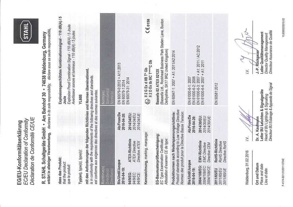
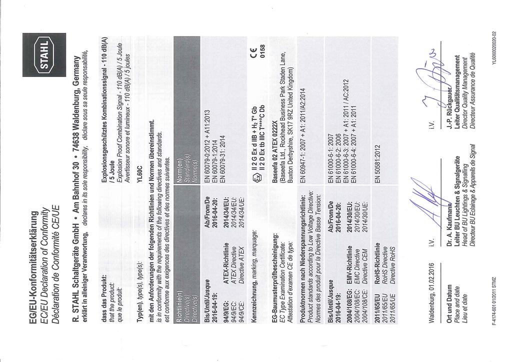
3 1.2 Information regarding the operating instructions ID-No.: Publication Code: The original instructions are the English edition. They are legally binding in all legal affairs. 1.3 Further documents Data sheet For documents in additional languages, see Explanation of the symbols 1.4 Conformity with standards and regulations See certificates and EU Declaration of Conformity: The device has IECEx approval. For certificate please refer to the IECEx homepage: 2 Explanation of the symbols 2.1 Symbols in these operating instructions Symbol Meaning Tips and recommendations on the use of the device General danger Danger due to explosive atmosphere Danger due to energised parts Explosion Proof Combination Signal - 3
4 Explanation of the symbols = Strobe = Sounder = Earth = Sounder = Telephone initiate 2.2 Warning notes Warnings must be observed under all circumstances, in order to minimize the risk due to construction and operation. The warning notes have the following structure: Signalling word: DANGER, WARNING, CAUTION, NOTICE Type and source of danger/damage Consequences of danger Taking countermeasures to avoid the danger or damage DANGER Danger to persons Non-compliance with the instruction results in severe or fatal injuries to persons. WARNING Danger to persons Non-compliance with the instruction can result in severe or fatal injuries to persons. CAUTION Danger to persons Non-compliance with the instruction can result in light injuries to persons. NOTICE Avoiding material damage Non-compliance with the instruction can result in material damage to the device and / or its environment. 4 Explosion Proof Combination Signal -
5 Safety notes 2.3 Symbols on the device Symbol Meaning CE marking according to the current applicable directive E E00 According to marking, device certified for hazardous areas. Input 15649E E00 Output 3 Safety notes 3.1 Operating instructions storage Read the operating instructions carefully and store them at the mounting location of the device. Observe applicable documents and operating instructions of the devices to be connected. 3.2 Safe use Read and observe the safety notes in these operating instructions! Observe characteristic values and rated operating conditions on the rating and data plates! Observe additional information plates on the device! Use the device in accordance with its intended and approved purpose only! We cannot be held liable for damage caused by incorrect or unauthorized use or by non-compliance with these operating instructions. Before installation and commissioning, make sure that the device is not damaged! Work on the device (installation, maintenance, overhaul, repair) may only be carried out by appropriately authorized and trained personnel. 3.3 Modifications and alterations DANGER Explosion hazard due to modifications and alterations to the device! Non-compliance results in severe or fatal injuries. Do not modify or alter the device. No liability or warranty for damage resulting from modifications and alterations. Explosion Proof Combination Signal - 5
6 Function and device design 4 Function and device design DANGER Explosion hazard due to improper use! Non-compliance results in severe or fatal injuries. Use the device only according to the operating conditions described in these operating instructions. 4.1 Function The explosion proof combination signal series YL60 is an audible and visual signal. It provides an audible and/or visual signal intended to alert, warn or draw attention to an event. It is designed for use in hazardous or harsh environments. In hazardous areas the devices have explosion protection for ATEX / IECEx Zones 1 & 2 for gas and 21 & 22 for dust. Gas groups covered are IIB & IIB + H2, dust protection for IIIC. UL certified variants offer protection to Class I Division I Gas groups BCD, Class II Division I Gas groups EFG. The device is not intended for continuos use. The life of the xenon flash tube is guaranteed for the following number of flashes: Variant Number of flashes 5 J 2 million 6 Explosion Proof Combination Signal -
7 5 Technical data Explosion Protection Global (IECEx) Gas and dust Europe (ATEX) Gas and dust North America (culus listed) Gas and dust IIB+H2, IIB E161818, E IIB+H2, IIB SL: UL / UL / UL 1203 / UL 1638 CSA C22.2 No. 30-M1986 / CSA C22.2 No. 25-M1966 / CSA E / CSA E Technical data IIB+H2 IECEx BAS X IIB IECEx BAS X IIB+H2, IIB IEC : 2011 / IEC : / IEC : 2008 IIB+H2 IIB Ex d IIB+H2 T4 Gb (Ta = C) Ex tb IIIC T135 C Db IP 66 (Ta = C) Ex d IIB+H2 T6 Gb (Ta = C) Ex tb IIIC T85 C Db IP 66 (Ta = C) Ex d IIB T4 Gb (Ta = C) Ex tb IIIC T135 C Db IP 66 (Ta = C) Ex d IIB T6 Gb (Ta = C) Ex tb IIIC T85 C Db IP 66 (Ta = C) IIB+H2 Baseefa02ATEX0222X IIB Baseefa02ATEX0212X IIB+H2, IIB : 2009 / : 2007 / : 2009 IIB+H2 IIB EII 2 G Ex d IIB+H2 T4 Gb (Ta = C) EII 2 D Ex tb IIIC T135 C Db IP 66 (Ta = C) EII 2 G Ex d IIB+H2 T6 Gb (Ta = C) EII 2 D Ex tb IIIC T85 C Db IP 66 (Ta = C) EII 2 G Ex d IIB T4 Gb (Ta = C) EII 2 D Ex tb IIIC T135 C Db IP 66 (Ta = C) EII 2 G Ex d IIB T6 Gb (Ta = C) EII 2 D Ex tb IIIC T85 C Db IP 66 (Ta = C) IIB+H2 CLASS I, DIVISION 1, GROUPS B, C and D, T4; CLASS II, DIVISION 1, GROUPS E, F and G; CLASS III CLASS 1, ZONE 1 AEx d IIB+H2 T4 CLASS 1, ZONE 1 Ex d IIB+H2 T4 Operating temperature C Audible signal appliance public mode with supplementary Visual signal appliance private mode IIB CLASS I, DIVISION 1, GROUPS C and D, T4; CLASS II, DIVISION 1, GROUPS E, F and G; CLASS III CLASS 1, ZONE 1 AEx d IIB T4 CLASS 1, ZONE 1 Ex d IIB T4 Operating temperature ºC Audible signal appliance public mode with supplementary Visual signal appliance private mode Explosion Proof Combination Signal - 7
8 Technical data Explosion Protection Certifications and certificates Certificates IECEx, ATEX, Brazil (INMETRO), India (PESO), Kazakhstan (TR), Russia (TR), Taiwan (ITRI), USA & Canada (culus), Belarus (TR) Technical Data Technical data Product weight Electrical data Rated operational voltage Rated operational current Mechanical data Material Enclosure Horn Lens cover Fixings Cable entries 6 kg 24 V DC, 48 V DC, 115 V AC and 230 V AC operational parameters + or -10 % 24 V DC 570 ma 48 V DC 435 ma 115 V AC 200 ma 230 V AC 100 ma aluminium, seawater resistant ABS, flame retardant polycarbonate stainless steel 2 cable entries, equipped with stopping plug (1x) and dust cap (1x) UL devices: equipped with M20 / 1/2 adapters (2x) Degree of protection IP66 IEC NEMA 4X UL 50 Operating temperature range Variant dependant see Explosion protection 8 Explosion Proof Combination Signal -
9 Transport and storage Technical Data Acoustic data Volume Polar diagram 110 db(a) / 1 m Horizontal plane Vertical plane 15288E00 Luminous characteristics Effective candela 5 J Clear Yellow 46 cd 42 cd Amber Red Blue 28 cd 14 cd 13 cd Green 10 cd Magenta N/A Candela seconds Flash energy Flash rate 5 J 9.3 lumens Clear lens 5 J 60 FPM For further technical data, see 6 Transport and storage Transport and store the device only in the original packaging. Store the device in a dry place (no condensation) and vibration-free. Do not drop the device. Explosion Proof Combination Signal - 9
10 Mounting and installation 7 Mounting and installation 7.1 Dimensions / fastening dimensions Dimensional Drawings (All Dimensions in mm [inches]) Subject to Alterations 18380E00 10 Explosion Proof Combination Signal -
11 Mounting and installation 7.2 Mounting / dismounting, operating position DANGER Risk of explosion! Risk of injuries and material damage! Terminal sleeves are fitted, they must be gas-tight and applied with a suitable tool. DANGER Explosion hazard! Risk of injuries and material damage! Carefully remove or replace the components. Exposed joint surfaces must not be damaged and must be protected from dust and dirt. Install the end flanges squarely without applying any force. Do not use a hammer or other tools when working on the flanges and do not use the fixing screws to pull down the flanges. Mount the device on a flat surface suitable for its weight. The tone output should be directed towards the area to be covered (see chapter Technical Data, Polar diagram). Insert the cables using certified and flameproof cable glands which are suitable for the gas group. Close unused entries using certified and flameproof stopping plugs Installation conditions for electrical connection DANGER Explosion hazard! Risk of injuries and material damage! Only use cable glands with corresponding certificate. The cable glands must be flameproof (Ex d) and suitable for the type of cable used. Close unused open holes in the enclosure with flameproof stopping plugs. Close unused cable glands using flameproof plugs. Cable glands, stopping plugs and plugs must meet the requirements of IEC/ Installation of the cable gland must be performed in accordance with the manufacturer's instructions. Cable entry temperature may exceed 70 C. To ensure degree of protection IP 66, a non-hardening sealant must be applied to the threads. DANGER Danger due to energised parts! Non-compliance results in severe or fatal injuries. Before opening and dismounting the device, disconnect it from the power supply. Secure the device against unauthorized switching. Explosion Proof Combination Signal - 11
12 Mounting and installation Access to the PCB E00 1 Screws ST 4,2 x 13 2 Horn cover 3 Cheese-head screws M5 x 16 4 Sounder flange 5 PCB 6 Enclosure Remove the 3 screwst 4,2 x 13 Lift horn cover Remove the 4 cheese-head screws M5 x 16 Lift sounder flange Disconnect pressure unit from PCB (see Electrical Connection, Key Components) Lift PCB to expose terminals for connection (see Electrical Connection, Wiring Diagrams for details) 12 Explosion Proof Combination Signal -
13 7.2.3 Reassembly of enclosure Inserting the PCB For correct positioning of the PCB there are 2 grooves in the enclosure. Depending on the version, insert the PCB in the corresponding groove! YL60/./D50/./.. YL60/./F50/./ E00 YL60/./L50/./.. YL60/./N50/./.. Mounting and installation Carefully insert the connected printed circuit board. Connect the horn flange to the printed circuit board. Set the horn flange on the enclosure. Do not clamp in any cables in the process. Insert the horn flange in a straight position without applying any pressure. Replace cheese-head screws M5 x 16 (see information below) and tighten the screws with a tightening torque of 3 Nm. Re-attach the cover. Tighten the ST 4.2 x 13 screws with a tightening torque of 0.4 Nm. Carefully assemble the device to ensure that the degree of protection is IP 66. The cheese-head screws are delivered with Nyltite seals (see the "Connection" section above). Check the Nyltite seals for damage before the installation. Tighten cheese-head screws with a torque of 3 Nm. Use the Nyltite seal a maximum of five times with the tightening torque E E00 Explosion Proof Combination Signal - 13
14 Mounting and installation Electrical connection Key Components E00 Key components YL60 DC Legend 7 = Terminal blocks 8 = Connector for sounder 9 = selection switch (ton table) 10 = Link for combined function (DC-version only) 0V LK1 +V LK E E00 Key components YL60 AC 7 Link connected: Strobe and sounder work together. Link removed: Strobe and sounder independent function. = Strobe = Sounder Cable Connection Approximately 20 cm (8 Inch) tails are required inside the enclosure for connection to the terminals on the PCB. This is especially important for installation using solid core cable. The terminals accept wires of 2.5 mm 2 or 14 to 18 AWG. 14 Explosion Proof Combination Signal -
15 Mounting and installation Interconnection of devices parallel Up to 10 devices with common supplies may be connected as a single system loop. Circuit diagrams Line monitoring for devices with DC Through reverse polarity By connecting an EOL resistor between 0 V and +V. The resistance value is defined by the system developer. Two signal levels for devices with DC Through reverse polarity By connecting a third electrical line. Two signal levels for devices with AC By connecting a third electrical line. DC version Combined function of sounder and strobe with one signal tone Connection to a 2-wire conductor 18400E00 Combined function of sounder and strobe with two signal tones Connection to a 3-wire conductor E E00 Explosion Proof Combination Signal - 15
16 Mounting and installation Connection to a 2-wire conductor - second tone by reverse polarity E00 Independent function of sounder and strobe Connection to a 4-wire conductor 0V LK1 +V LK E E00 Remove jumper from LK1 and LK2 Connection: Strobe TB1 Sounder TB2 Second tone by reverse polarity or 3-wire connection to TB2, as shown above in connection diagrams E00 Combined function of sounder and strobe - activation by telephone signal Sounder and strobe are activated by a telephone signal. The function is retained as long as the telephone signal is available. The strobe can flash up to four times after deactivating the telephone signal E00 16 Explosion Proof Combination Signal -
17 AC version Combined function of sounder and strobe with one signal tone Connection to a 2-wire conductor 18414E00 Combined function of sounder and strobe with two signal tones Connection to a 3-wire conductor 1 2 Mounting and installation Bridge TB1 and TB2 using a conductor E E00 Independent function of sounder and strobe Connection to a 3-wire conductor Second tone via connection to TB4 possible (see above) E00 Explosion Proof Combination Signal - 17
18 Mounting and installation Combined function of sounder and strobe - activation by telephone signal Sounder and strobe are activated by a telephone signal. The function is retained as long as the telephone signal is available. The strobe can flash up to four times after deactivating the telephone signal E00 = Strobe = Sounder = Earth Earth connection = Sounder = Telephone initiate 15265E00 The unit must be connected to a good quality earth. The internal Earth connection is the primary point. The external connection is for a supplementary bonding connection and is used where local code or authorities permit or require such connection. 18 Explosion Proof Combination Signal -
19 7.2.6 Sound tone selection Mounting and installation For signal tone selection and its switch positions refer to the table below. Check if the correct switch positions of the selected signal tones have been selected. table no Version Frequency Sound selection switch (ON = 1) Repetition rate (sec) Special application Alternate two-tone Fire alarms - Level crossing Alternate two-tone Security alarms Alternate fast two-tone Increased urgency - Level crossing Alternate fast two-tone Security deterrent Alternate two-tone /0.1 AFNOR, France Alternate two-tone Alternate very fast two-tone Alternate very fast two-tone Alternate two-tone Turn out, Sweden (SS ) Continuous tone All clear, Sweden (SS ) Continuous tone Continuous tone Continuous tone Continuous tone Interrupted tone Interrupted tone AS2220, Australia Interrupted tone Interrupted tone Interrupted tone Explosion Proof Combination Signal - 19
20 Mounting and installation table Interrupted tone /12 Important message, Sweden 20 Interrupted tone Interrupted tone Air-raid alarm, Sweden 22 Interrupted tone Local warning, Sweden 23 Interrupted tone /0.3 Industrial alarm, Germany 24 Interrupted, fast, rising volume 26 Fast siren Rising constantly, falling ISO 8201 Evacuation As standard Fast whoop /40/10 Industrial alarm, Germany The PFEER sound signals recommended by UKOOA are: International evacuation alarm Slow whoop Evacuation, The Netherlands Reverse sweep Fire alarm, Germany (DIN 33404) Siren General alarm Sound signal 15 Interrupted tone 1000 Hz PAPA Sound signal 31 Reverse sweep Hz Toxic gas Sound signal 11 Continuous tone 1000 Hz Sound selection switch detail ON= ON = 1 1 ON SW1 ON SW2 ON SW E E00 Standard Telephone initiate 20 Explosion Proof Combination Signal -
21 Commissioning 7.3 Installation 8 Commissioning WARNING Danger of electric shock due to energised parts! Non-compliance can result in severe or fatal injuries. All connections and wiring must be disconnected from the power supply. Secure the connections against unauthorized switching. DANGER Explosion hazard! Risk of injuries and material damage! Operate the device only if it is not damaged. If the thread is damaged, the device must be replaced immediately. Handle the device and the components very carefully. Exposed joint surfaces must be protected from dust, dirt and damage. Mount the end flanges squarely and do not apply any force. Do not use a hammer or any other metal instruments to work on the flange. Do not use the fixing screws to pull down the flange. Install the device only in a clean and dry operating environment. DANGER Explosion hazard due to incorrect installation! Non-compliance results in severe or fatal injuries. Check the device for proper installation and function before commissioning. Comply with the national regulations. Before commissioning, ensure the following: the device has been installed according to regulations. the power supply voltage and the rated operational voltage are identical. the required cable diameter for cable glands has been used. the cable entries and stopping plugs have been securely tightened. the cables are correctly connected. the connection has been performed correctly. all screws and nuts are tightened according to regulations. the connection chamber is clean. the device is not damaged. no foreign bodies are inside the device. the device is sealed according to regulations. Explosion Proof Combination Signal - 21
22 Operation 9 Operation The device is used to warn and alert by means of a sound signal. of a visual signal. 9.1 Troubleshooting If an error occurs please re-visit the earlier sections of this document. If the error cannot be eliminated using the mentioned procedures: Contact R. STAHL Schaltgeräte GmbH. For fast processing, have the following information ready: Type and serial number Purchase information Error description Intended use (in particular input / output wiring) 10 Maintenance, overhaul, repair WARNING Risk of electric shock or malfunctioning of the device due to unauthorized work! Non-compliance can result in severe injuries and material damage. Work performed on the device must only be carried out by appropriately authorized and qualified electricians. 22 Explosion Proof Combination Signal -
23 10.1 Maintenance Maintenance, overhaul, repair Determine the type and extent of inspections in compliance with the relevant national regulations. Adapt inspection intervals to the operating conditions. The following tests and measures must be carried out during regular maintenance Repair Observe the relevant national regulations in the country of use. Check the permissible ambient temperature the enclosure components for formation of cracks and damage. its intended use if the conductors are clamped properly the cables for ageing and damage the seals for ageing and damage Measures If exceeding the permissible ambient temperature or falling below the device must be taken out of operation. Replace the exchangeable enclosure components. If the enclosure components are non-exchangeable, the device must be taken out of operation. If the device is not used according to its intended use, it must be taken out of operation. clamp loose conductors tightly. replace damaged or aged cables. replace damaged, aged and porous seals and completely change enclosure components with foamed seal. DANGER Explosion hazard due to improper repair! Non-compliance results in severe or fatal injuries. Repair work on the devices must be performed only by R. STAHL Schaltgeräte GmbH. Explosion Proof Combination Signal - 23
24 Cleaning 10.3 Returning the device Only return or package the devices after consulting R. STAHL! Contact the responsible representative from R. STAHL. R. STAHL's customer service is available to handle returns if repair or service is required. Contact customer service personally. or Go to the website. Under "Support" > "RMA form", select "Request RMA slip". Fill out the form and send it. Confirmation will be sent. R. STAHL's customer service will contact you. You will receive an RMA slip after speaking with customer service. Send the device along with the RMA slip in the packaging to R. STAHL Schaltgeräte GmbH (refer to Section 1.1 for the address). 11 Cleaning Clean the device only with a cloth, brush, vacuum cleaner or similar items. When cleaning with a damp cloth, use water or mild, non-abrasive, non-scratching cleaning agents. Do not use aggressive detergents or solvents. 12 Disposal Observe national and local regulations and statutory regulation regarding disposal. Separate materials when sending it for recycling. Ensure environmentally friendly disposal of all components according to the statutory regulations. 13 Accessories and spare parts NOTICE Malfunction or damage to the device due to the use of non-original components. Non-compliance can result in material damage. Use only original accessories and spare parts from R. STAHL Schaltgeräte GmbH. For accessories and spare parts, see data sheet on our homepage 24 Explosion Proof Combination Signal -
25
26
Flameproof Manual Call Points
 Operating instructions Additional languages www.r-stahl.com CS & Clifford & Snell Contents General Information.... Manufacturer.... Information regarding the operating instructions.... Further documents....
Inspection Light LED 6149/2. Operating instructions EN EN EN EN EN EN EN EN EN EN EN EN EN EN EN EN EN EN EN EN EN EN EN EN
 Inspection Light LED Operating instructions Additional languages www.stahl-ex.com Contents 1 General Information...3 1.1 Manufacturer...3 1.2 Information regarding the operating instructions...3 1.3 Conformity
OPERATING AND INSTALLATION
 A division of Signature Ind. Ltd YO6 YL6 V6 DIMENSIONS (mm) 280mm 11 OPERATING AND INSTALLATION INSTRUCTIONS FOR (UL & ATEX) YODALEX FLAMEPROOF AUDIBLE AND VISUAL ALARMS D7292 OPERATING CLASS 1 DIVISION
GRP Flameproof Combination Signal db(a) / 5 Joule Series YL6S
 / 5 Joule Series YL6S") www.stahl.de > Corrosion resistant omnidirectional high output sounder > Integrated Ex d enclosure > Extreme temperature range > 3 stage alarm with independant tone selection for V DC systems > IP66 IP67
www.stahl.de > Corrosion resistant omnidirectional high output sounder > Integrated Ex d enclosure > Extreme temperature range > 3 stage alarm with independant tone selection for V DC systems > IP66 IP67
INSTRUCTION MANUAL (ATEX / IECEx)
") INSTRUCTION MANUAL (ATEX / IECEx) BExS110D and BExS110D-R Sounder For use in Flammable Gas and Dust Atmospheres BExS110D BExS110D-R 1) Warnings DO NOT OPEN WHEN AN EXPLOSIVE ATMOSPHERE IS PRESENT DO NOT
INSTRUCTION MANUAL (ATEX / IECEx) BExS110D and BExS110D-R Sounder For use in Flammable Gas and Dust Atmospheres BExS110D BExS110D-R 1) Warnings DO NOT OPEN WHEN AN EXPLOSIVE ATMOSPHERE IS PRESENT DO NOT
Explosion Proof Combination Signal db (A) / 5 Joule Series YL60
 / 5 Joule Series YL60") www.stahl.de Explosion Proof Combination Signal - 110 db (A) / 5 Joule > Omnidirectional high output sounder 110 db (A) / 1 m > 5 Joule xenon strobe > 2 stage alarm, independently selectable 2nd stage
www.stahl.de Explosion Proof Combination Signal - 110 db (A) / 5 Joule > Omnidirectional high output sounder 110 db (A) / 1 m > 5 Joule xenon strobe > 2 stage alarm, independently selectable 2nd stage
INSTRUCTION & SERVICE MANUAL
 INSTRUCTION & SERVICE MANUAL D2xC1 ALARM HORN AND STROBE For Use In Hazardous Locations 3) Ratings and Markings 3.1 ATEX / IECEx certification The D2xC1 Alarm Horn and Strobe complies with the following
Multiple Status Indicators Series MEXE, MS25, MS35, MS45, MS55
 www.stahl.de > Pre-wi ready-to-use multi-signalling unit > Corrosion resistant > Suitable for offshore / onshore harsh environments > Incorporates the FX15 GRP beacon YA90 for visual audible notification
PATROL SOUNDERS 100/105 db(a) PA 1 / PA 5
 PA 1 / PA 5") PRODUCTS AUDIBLE SIGNALING DEVICES PATROL SOUNDERS 100/105 db(a) PA 1 / PA 5 PATROL the new generation of sounders. Three dimensional innovation. Safe; an incorrect installation is virtually impossible.
PRODUCTS AUDIBLE SIGNALING DEVICES PATROL SOUNDERS 100/105 db(a) PA 1 / PA 5 PATROL the new generation of sounders. Three dimensional innovation. Safe; an incorrect installation is virtually impossible.
PATROL SOUNDERS 110/120 db(a) PA 10 / PA 20
 PA 10 / PA 20") PRODUCTS AUDIBLE SIGNALING DEVICES PATROL SOUNDERS 110/120 db(a) PA 10 / PA 20 PATROL the new generation of sounders. Three dimensional innovation. Safe; an incorrect installation is virtually impossible.
PRODUCTS AUDIBLE SIGNALING DEVICES PATROL SOUNDERS 110/120 db(a) PA 10 / PA 20 PATROL the new generation of sounders. Three dimensional innovation. Safe; an incorrect installation is virtually impossible.
Global Series. Installation and Maintenance Instructions. Model G-STR Strobe Beacon. For Use in Hazardous Locations
 Global Series Model G-STR Strobe Beacon For Use in Hazardous Locations Ex d Surface Mount Ex de Surface Mount Installation and Maintenance Instructions 25500185 Rev. B4 1217 Printed in U.S.A. Limited Warranty
Flameproof Manual Call Points Series MCP
 > Light weight glass reinforced polyester (GRP) Ex d enclosure > Weather resistant high performance red paint finish as standard > Break glass version supplied with test key > Push button version supplied
INSTRUCTION & SERVICE MANUAL
 INSTRUCTION & SERVICE MANUAL D1xC COMBINED RADIAL HORNS & STROBES For Use In Hazardous Locations - Gas 3) Ratings and Markings The D1xC1 and D1xC2 combined alarm horns and strobes comply with the following
Integrated Solutions Low Voltage Systems
 Integrated Solutions Low Voltage Systems 612 Contents Energy Distribution Overview Module Technology 8146 614 Overview Flameproof Enclosures 8220 614 Overview Flameproof Enclosures 8261 614 Overview CUBEx
INSTRUCTION MANUAL. D2xB1XH1 & D2xB1XH2 Xenon Beacons For use in Hazardous Locations
 INSTRUCTION MANUAL D2xB1XH1 & D2xB1XH2 Xenon Beacons For use in Hazardous Locations synchronization requirements of UL1971 & UL1638 / CAN/ULCS526. 2.2 NEC & CEC Class / Division Ratings for US / Canada
INSTRUCTION & SERVICE MANUAL D1xS1 & D1xS2 ALARM HORNS For Use In Hazardous Locations - Gas
 INSTRUCTION & SERVICE MANUAL D1xS1 & D1xS2 ALARM HORNS For Use In Hazardous Locations - Gas UL 1203 CSA C22.2 NO. 30-M1986 The D1xS1 and D1xS2 Alarm Horns also comply with the following standards for signaling
standards: standards:
 INSTRUCTION MANUAL D2xB1LD2 LED Beacons For use in Hazardous Locations 1) Warnings DO NOT OPEN WHEN AN EXPLOSIVE ATMOSPHERE IS PRESENT DO NOT OPEN WHEN ENERGISED POTENTIAL ELECTROSTATIC CHARGING HAZARD
YO3 - YO4 / YL4 - YO5 / YL5
 C l i f f o r d & S n e l l YO3IS YO4IS DIMENSIONS mm 81(3.2 ) 90(3.5 ) YO3 - YO4 / YL4 - YO5 / YL5 Intrinsically Safe Audible and Visual Alarms ATEX YO5IS YL4IS YL5IS 90(3.5 ) 81(3.2 ) MAIN FEATURES BASEEFA
INSTRUCTION MANUAL. E2xB05 & E2xB10 Xenon Beacons For use in Hazardous Locations
 INSTRUCTION MANUAL E2xB05 & E2xB10 Xenon Beacons For use in Hazardous Locations 1) Warnings DO NOT OPEN WHEN AN EXPLOSIVE ATMOSPHERE IS PRESENT DO NOT OPEN WHEN ENERGISED POTENTIAL ELECTROSTATIC CHARGING
X10 Mini, Midi & Maxi
 Industrial Sounder, Sounder Beacon X0 Mini, Midi & Maxi Installation Manual EAT X0 Mini, Midi & Maxi Installation Manual (90F) Contents Overview and purpose... Product assembly... Select wiring method......
INSTRUCTION MANUAL (ATEX/IECEx/SIL2) BExBG05D-SIL Flameproof Xenon SIL 2 Beacons For use in Flammable Gas and Dust Atmospheres
 BExBG05D-SIL Flameproof Xenon SIL 2 Beacons For use in Flammable Gas and Dust Atmospheres") INSTRUCTION MANUAL (ATEX/IECEx/SIL2) BExBG05D-SIL Flameproof Xenon SIL 2 Beacons For use in Flammable Gas and Dust Atmospheres 1) Introduction The BExBG05D-SIL is a flameproof beacon which is certified
INSTRUCTION MANUAL (ATEX/IECEx/SIL2) BExBG05D-SIL Flameproof Xenon SIL 2 Beacons For use in Flammable Gas and Dust Atmospheres 1) Introduction The BExBG05D-SIL is a flameproof beacon which is certified
INSTRUCTION MANUAL. D1xB2XH2 Xenon Beacon For use in Hazardous Locations. 2) Rating & Marking Information
 Rating & Marking Information") INSTRUCTION MANUAL D1xB2XH2 Xenon Beacon For use in Hazardous Locations 2) Rating & Marking Information 2.1 Public Mode Fire Alarm Ratings The D1xB2XH2 is certified for use as public mode visual alarm
INSTRUCTION MANUAL D1xB2XH2 Xenon Beacon For use in Hazardous Locations 2) Rating & Marking Information 2.1 Public Mode Fire Alarm Ratings The D1xB2XH2 is certified for use as public mode visual alarm
INSTRUCTION MANUAL. D1xB2XH1 Xenon Beacon For use in Hazardous Locations. 2) Rating & Marking Information
 Rating & Marking Information") INSTRUCTION MANUAL D1xB2XH1 Xenon Beacon For use in Hazardous Locations 2) Rating & Marking Information 2.1 Public Mode Fire Alarm Ratings The D1xB2XH1 is certified for use as public mode visual alarm
INSTRUCTION MANUAL D1xB2XH1 Xenon Beacon For use in Hazardous Locations 2) Rating & Marking Information 2.1 Public Mode Fire Alarm Ratings The D1xB2XH1 is certified for use as public mode visual alarm
INSTRUCTION MANUAL (ATEX/IECEx/SIL2)
") INSTRUCTION MANUAL (ATEX/IECEx/SIL2) BExS110D-SIL Flameproof Sounders For use in Flammable Gas Atmospheres BExS110D-SIL 1) Warnings DO NOT OPEN WHEN AN EXPLOSIVE ATMOSPHERE IS PRESENT DO NOT OPEN WHEN
INSTRUCTION MANUAL (ATEX/IECEx/SIL2) BExS110D-SIL Flameproof Sounders For use in Flammable Gas Atmospheres BExS110D-SIL 1) Warnings DO NOT OPEN WHEN AN EXPLOSIVE ATMOSPHERE IS PRESENT DO NOT OPEN WHEN
Yodalarm. Sounders. Pg Y03 Y04/YL4 Y05/YL5 Y08/YL8/Y08 SUPER/ YL8 SUPER V4 V6/Y06/YL6 Carillon
 Sounders Y03 Y04/YL4 Y05/YL5 Y08/YL8/Y08 SUPER/ YL8 SUPER V4 V6/Y06/YL6 Carillon Pg 185 186 187 188 189 190 191 Y03 1YA030207 1YA030203 1YA030205 YL030/24 A1:2002 YL030110/230 UL464 C22.2 No. M1983 BS
Additional Operating Instructions SITRANS F. Vortex flowmeters. SITRANS FX330 Ex-d.
 Additional Operating Instructions SITRANS F Vortex flowmeters Ex-d Edition 09/208 CONTENTS Safety instructions 3. General notes... 3.2 EU conformity... 3.3 Approval according to the IECEx scheme... 3.4
4) Intrinsic Safety Certification
 Intrinsic Safety Certification") INSTRUCTION MANUAL Minialert Intrinsically Safe Round Combined Unit Section Volume Control Tone Generator S2 S3 Tone Selection Switches Fig 1 Simplified block diagram The combined unit is CE marked for
INSTRUCTION MANUAL Minialert Intrinsically Safe Round Combined Unit Section Volume Control Tone Generator S2 S3 Tone Selection Switches Fig 1 Simplified block diagram The combined unit is CE marked for
Flameproof Manual Call Points Series MCP
 > Light weight glass reinforced polyester (GRP) Ex d enclosure > Weather resistant high performance red paint finish as standard > Break glass version supplied with test key > Push button version supplied
Technical Manual for the Horn DB1P UL DB1HP UL
 Technical Manual for the Horn DB1P UL DB1HP UL Please note that every care has been taken to ensure the accuracy of our technical manual. We do not, however, accept responsibility for damage, loss or expense
EX-TECH SIGNALLING SAS SD100-1 WEATHERPROOF SOUNDER/HORN TECHNICAL MANUAL
 PRODUCT NAME: SD-100-1- WEATHER-PROOF SOUNDER/HORN DOC NO.: EX-TECH SIGNALLING SAS-12-SD100-1-TM REV03 WEATHERPROOF SOUNDER/HORN IP66 SD-100 SERIES EX-TECH SIGNALLING SAS SD100-1 WEATHERPROOF SOUNDER/HORN
Explosion Proof Manual Call Points Series MCP
 > Light weight glass reinforced polyester (GRP) Ex d enclosure > Weather resistant high performance red paint finish as standard > Break glass version supplied with test key > Push button version supplied
Operating Instructions
 Important information: These instructions contain safety information, read and follow them carefully. Dialight will not accept any responsibility for injury, damage or loss which may occur due to incorrect
USER MANUAL FOR EXPLOSION PROTECTED FLUORESCENT LIGHT FITTING type PSF 218
 CONTENT 1. Manufacturer 1 2. General safety informations 1 3. Purpose 2 4. Product compliance 2 5. Degree of protection and technical data 2 6. Type 3 7. Mounting and installation 3 8. Dimensions 6 9.
OPTIWAVE X500 Supplementary Instructions
 OPTIWAVE X500 Supplementary Instructions OPTIWAVE 3500 C OPTIWAVE 6500 C OPTIWAVE 7500 C Supplementary Instructions for ATEX applications KROHNE CONTENTS OPTIWAVE X500 1 General safety information 4 1.1
Additional Operating Instructions SITRANS F. Vortex flowmeters. SITRANS FX330 Ex-nA.
 Additional Operating Instructions SITRANS F Vortex flowmeters Ex-nA Edition 08/207 CONTENTS Safety instructions 3. General notes... 3.2 EU conformity... 3.3 Approval according to the IECEx scheme... 3.4
INSTRUCTION MANUAL (ATEX / IECEx)
") INSTRUCTION MANUAL (ATEX / IECEx) BExTS110D Flameproof Sontel 1) Introduction The BExTS110D is a flameproof Sontel telephone sounder which is certified to the meet the requirements of the ATEX directive
INSTRUCTION MANUAL (ATEX / IECEx) BExTS110D Flameproof Sontel 1) Introduction The BExTS110D is a flameproof Sontel telephone sounder which is certified to the meet the requirements of the ATEX directive
Manual Power relay SR853
 Manual Power relay SR853 Product types SR853.8.x.x, Rev. 1 SR853 manual page2 The symbols WARNING, CAUTION, NOTE This symbol warns of a serious hazard. Failure to observe this warning may result in death
Installation manual surface mounting plugs and socket outlets, panel mounting plugs and socket outlets with screw connection (16/32 A)
") EN Installation manual surface mounting plugs and socket outlets, panel 60003214 Issue 04.2016 2016-04-01 Table of contents 1 About this manual 3 1.1 Structure of the warnings 3 1.2 Symbols used 4 1.3
EN Installation manual surface mounting plugs and socket outlets, panel 60003214 Issue 04.2016 2016-04-01 Table of contents 1 About this manual 3 1.1 Structure of the warnings 3 1.2 Symbols used 4 1.3
Additional Operating Instructions SITRANS F. Vortex flowmeters. SITRANS FX330 Ex-i.
 Additional Operating Instructions SITRANS F Vortex flowmeters Ex-i Edition 09/2018 CONTENTS 1 Safety instructions 3 1.1 General notes... 3 1.2 EU conformity... 3 1.3 Approval according to the IECEx scheme...
Immersion heaters for ATEX/IECEx hazardous areas or in non-atex version
 for ATEX/IECEx hazardous areas or in non-atex version * Non contractual picture Warning It is imperative to read these instructions carefully before installing or maintaining the equipment. MI100EN 09/2017
Certificate of Compliance
 FF0 001 Certificate of Compliance Certificate: 70116279 (LR 025993_0_000) Issued to: General Monitors, Incorporated 26776 Simpatica Circle Lake Forest, California 92630 USA Attention: Larry Vlagea The
SCHMIDT Flow Sensor SS Ex - Supplementary instructions for use in explosive atmospheres ATEX
 SCHMIDT Flow Sensor SS 20.600 Ex - Supplementary instructions for use in explosive atmospheres ATEX SCHMIDT Flow Sensor SS 20.600 Ex ATEX version Table of Contents 1 Important information... 3 2 Storage
Certificate of Compliance
 FF0 001 Certificate of Compliance Certificate: 70116284 (LR 064969_0_00) Issued to: Mine Safety Appliances Company North American Division 1000 Cranberry Woods Dr Cranberry Township, Pennsylvania 16066-5296
PILOT VALVE ENCLOSURES FOR HAZARDOUS LOCATIONS PENTAIR CLEAN AIR SYSTEMS
 PENTAIR CLEAN AIR SYSTEMS 3-VFD COMBINATION FLAME AND DUST IGNITION PROOF ENCLOSURES Goyen pilot valve enclosures for hazardous locations are available in a combination of flame proof and dust ignition
Instruction Manual. Alarm Unit For Low Gas Level # Read manual before use! Observe all safety information! Keep manual for future use!
 Mess-, Regel- und Überwachungsgeräte für Haustechnik, Industrie und Umweltschutz Lindenstraße 20 74363 Güglingen Telefon +49 7135-102-0 Service +49 7135-102-211 Telefax +49 7135-102-147 info@afriso.de
INSTRUCTION MANUAL IS-mB1 Minialite Intrinsically Safe Round LED Beacon
 INSTRUCTION MANUAL Minialite Intrinsically Safe Round LED This instruction sheet describes installations which conform to EN60079:Part14:2008 Electrical Installation in Hazardous Areas. When designing
LIGHTING TEF 9980 STATUS LIGHT, MAIN LIGHT & REPEATER LIGHT ZONE 1, ZONE 2 & SAFE AREA USER MANUAL
 Subject to change without prior notice TUM7 REV. B.08.08 SAFETY INSTRUCTIONS The TEF 9980 status light may be installed in Zone, or safe area. The Equipment shall not be installed in Zone 0! HANDLE WITH
Translation of the assembly instructions with operating instructions and technical appendix
 BA Ex-SBU Switch box type SBU-x(1,2,3)x Translation of the assembly instructions with operating instructions and technical appendix In accordance with EU ATEX Directive 2014/32/EU In accordance with EU
Installation manual extra-low-voltage socket outlets for panel- and surface-mounting
 EN Installation manual extra-low-voltage socket outlets for panel- and 60003221 Issue 04.2016 2016-04-01 Table of contents 1 About this manual 3 1.1 Structure of the warnings 3 1.2 Symbols used 4 1.3 Signal
Circulation heaters for ATEX/IECEx hazardous areas or in non-atex version
 for ATEX/IECEx hazardous areas or in non-atex version * Non contractual picture Warning It is imperative to read these instructions carefully before installing or maintaining the equipment. MI500EN 09/2017
Nexus 120 DC Sounder Nexus 120 DC Sounder with 5J Xenon Beacon Nexus 120 DC Sounder with LED Beacon
 Nexus 120 DC Sounder Nexus 120 DC Sounder with 5J Xenon Beacon Nexus 120 DC Sounder with LED Beacon Technical Specification 1. Sounder Supply Voltage Range 10-60V DC Current 0.12 0.55A* (Typ. 0.5A @ 24V,
Regulated Ex-Heater HEX with internal controller, HEX with external controller II 3 G II 3 D
 Regulated Ex-Heater HEX5-1.08 with internal controller, HEX5-2.08 with external controller II 3 G II 3 D Instruction Manual Version 1.02.00 Dear customer, we have made up this operating manual in such
Duct heaters for ATEX/IECEx hazardous areas or in non-atex version
 for ATEX/IECEx hazardous areas or in non-atex version * Non contractual picture Warning It is imperative to read these instructions carefully before installing or maintaining the equipment. MI200EN 09/2017
PILOT VALVE ENCLOSURES FOR HAZARDOUS LOCATIONS
 3-VFD COMBINATION FLAME AND DUST IGNITION PROOF ENCLOSURES Goyen pilot valve enclosures for hazardous locations are available in a combination of flame proof and dust ignition proof assemblies, where,
E2S Datasheet v10a. The IS-mA1 is suitable for all intrinsically safe signalling applications including fire, security and process control.
 E2S Datasheet 1.2.1 v10a ISmA1 ISminialarm The ISmA1 is a compact, 100dB(A) alarm sounder. Approvals include ATEX, IECEx and GOSTR for Zone 0 applications and FM approval for Class I Division 1 and Class
USER MANUAL FOR EXPLOSION PROTECTED FLUORESCENT LIGHT FITTING type PSF 236
 CONTENT 1. Manufacturer 1 2. General safety informations 1 3. Purpose 2 4. Product compliance 2 5. Degree of protection and technical data 2 6. Type 3 7. Mounting and installation 3 8. Dimensions 6 9.
Officine Meccaniche M.A.M. series for command, control, signaling and/or automation. DOCUMENT IS-EJB-A-14 rev. 0
 Officine Meccaniche M.A.M. Apparecchiature Antideflagranti DOCUMENT IS-EJB-A-14 rev. 0 Instructions Flameproof enclosures EJB../W series for command, control, signaling and/or automation Emission date:
MANUAL Oil Level Sensor
 PROCESS AUTOMATION MANUAL Oil Level Sensor KVF-104-PF ISO9001 0102 With regard to the supply of products, the current issue of the following document is applicable: The General Terms of Delivery for Products
Certificate of Compliance
 FF02 Certificate of Compliance Certificate: 70068210 Issued to: Cascade Technologies Ltd Glendevon House, Castle Business Park, Stirling, Scotland. UNITED KINGDOM FK9 4TZ Attention: Mr M Douglas. The products
Installation manual plugs and connectors QUICK-CONNECT (63 A)
") EN Installation manual plugs and connectors QUICK-CONNECT (63 A) 60003217 Issue 04.2016 2016-04-01 Table of contents 1 About this manual 3 1.1 Structure of the warnings 3 1.2 Symbols used 4 1.3 Signal
EN Installation manual plugs and connectors QUICK-CONNECT (63 A) 60003217 Issue 04.2016 2016-04-01 Table of contents 1 About this manual 3 1.1 Structure of the warnings 3 1.2 Symbols used 4 1.3 Signal
TECHNICAL MANUAL EXPLOSION PROOF STATUS LIGHT / LAMP BSL 125 / BSL 150. Scope: EXcite USER MANUAL BSL 125 / BSL 150. Date:
 Page 1 of 9 TECHNICL MNUL EXPLOSION PROOF STTUS LIGHT / LMP TEX Marking: Code: II 2GD EPL Gb, Db Ex d IIC T4/T5/T6 IP66 Ex tb IIIC TXXX C Marking details: Please note that every care has been taken to
DSF xx10.xx xhv Ex-Atex Hall Effect Single Channel Speed Sensor
 Product ID Type # Product # Drawing # DSF 1210.00 SHV Ex-atex (2m) 374Z-05066 110428F1 DSF 1210.00 SHV Ex-atex (5m) 374Z-05176 110428F1 DSF 1210.00 SHV Ex-atex (10m) 374Z-05590 110428F1 DSF 1410.00 SHV
Product Manual Standard Asserta Sounder Range
 Product Manual Standard Asserta Sounder Range Document Structure: Steve Martin - 18/09/08 Technical Information: Chris Anderson - 14/10/08 Cooper Fulleon Ltd Llantarnam Park Cwmbran South Wales NP44 3AW
INSTRUCTION MANUAL (ATEX)
") INSTRUCTION MANUAL (ATEX) ISmA1M Minialarm Intrinsically Safe Round ISmA1M Volume Control Tone Generator S3 Tone Selection Switches Fig 1 Simplified block diagram The ISmA1M sounder is CE marked for compliance
INSTRUCTION MANUAL (ATEX) ISmA1M Minialarm Intrinsically Safe Round ISmA1M Volume Control Tone Generator S3 Tone Selection Switches Fig 1 Simplified block diagram The ISmA1M sounder is CE marked for compliance
EJBX. Ex d. AISI 316L stainless steel. - Zone 1, 2, 21, 22 - Group IIB+H2 - Stainless steel junction boxes - Choice of 13 sizes - IP 66 / 67
 Ex d EJBX AISI 316L stainless steel - Zone 1, 2, 21, 22 - Group IIB+H2 - Stainless steel junction boxes - Choice of 13 sizes - IP 66 / 67 Quartz sand blasting Warning labels Mounting bracket Silicone gasket
Installation and Operating instructions for. C9900-U battery pack. Version: 2.0 Date:
 Installation and Operating instructions for C9900-U330-0010 battery pack Version: 2.0 Date: 2017-03-23 Table of contents Table of contents 1 Foreword 3 1.1 Notes on the Documentation 3 1.1.1 Liability
E2S Datasheet v10a
 E2S Datasheet 1.2.3 v10a ISmC1 ISminialert The ISmC1 is a compact combined 100dB(A) alarm sounder and L.E.D. beacon only one Zener barrier or galvanic isolator required to run both sounder & beacon or
Technical Manual for the Alarm Pull Station PH1
 Technical Manual for the Alarm Pull Station PH1 Please note that every care has been taken to ensure the accuracy of our technical manual. We do not, however, accept responsibility for damage, loss or
Signaling Devices. Acoustic Signaling Devices 298. Optical Signaling Devices 309. Bosch Security Systems B.V.
 Signaling Devices Acoustic Signaling Devices 28 Optical Signaling Devices 30 26 Signaling Devices Acoustic Signaling Devices Acoustic Signaling Devices MSS300-SA SG 200 DS 10 LSN/GLT GLT GLT GLT Operating
Drive Technology \ Drive Automation \ System Integration \ Services * _0817* Inquiry Forms for Explosion-Proof Gearmotors
 Drive Technology \ Drive Automation \ System Integration \ Services *23511257_0817* Inquiry Forms for Explosion-Proof Gearmotors Edition 08/2017 23511257/EN SEW-EURODRIVE Driving the world Inquiry forms
MAINS KLARGESTER SEPARATOR ALARM INSTALLATION & OPERATIONS MANUAL
 MAINS KLARGESTER SEPARATOR ALARM INSTALLATION & OPERATIONS MANUAL Contents IMPORTANT... 3 General Description... 4 General Operation... 4 Changing Factory Settings... 4 Alarm Type... 4 Check Interval...
Engineering Guideline. pac- Carriers Type Universal
 Engineering Guideline pac- Carriers Type 9195 Universal Integration of conventional process automation interfaces pac- Carrier The pac- Carrier reflects the intention of R. STAHL to provide state-of-the-art
Explosion Proof Line Powered Telephone Ringer
 Explosion Proof Line Powered Telephone Ringer P7020 CE20 Without Projection Horn P7021 CE20 With Projection Horn P004572 Rev. E 180416 4/16/2018 12:32 PM Ph: 403.258.3100 \ email:info@guardiantelecom.com
Installation manual surface mounting plugs and socket outlets, panel mounting plugs and socket outlets QUICK-CONNECT (63 A)
") EN Installation manual surface mounting plugs and socket outlets, panel 60003506 Issue 04.2016 2016-04-01 Table of contents 1 About this manual 3 1.1 Structure of the warnings 3 1.2 Symbols used 4 1.3
EN Installation manual surface mounting plugs and socket outlets, panel 60003506 Issue 04.2016 2016-04-01 Table of contents 1 About this manual 3 1.1 Structure of the warnings 3 1.2 Symbols used 4 1.3
VERSAFLOW VORTEX Supplementary instructions
 VERSAFLOW VORTEX Supplementary instructions Vortex flowmeter Equipment category II 2G CONTENTS VERSAFLOW VORTEX 1 Safety instructions 3 1.1 General notes... 3 1.2 EC conformity... 3 1.3 Approval according
Erik Leider Project Engineer Hazardous Locations, Gas & Oil Underwriters Laboratories
 Hazardous Locations: Understanding the Basics of Global Compliance Requirements Erik Leider Project Engineer Hazardous Locations, Gas & Oil Underwriters Laboratories DISCLAIMER/ TERMS OF USE: THE INFORMATION
User Manual GV25 GV35 GV702. Company information: Original instructions GV12066 (1)
") User Manual Original instructions GV25 GV35 GV702 Company information: www.vipercleaning.eu info-eu@vipercleaning.com GV12066 (1) 2012-04-10 USER MANUAL ENGLISH TABLE OF CONTENTS Introduction... 4 Manual
User Manual Original instructions GV25 GV35 GV702 Company information: www.vipercleaning.eu info-eu@vipercleaning.com GV12066 (1) 2012-04-10 USER MANUAL ENGLISH TABLE OF CONTENTS Introduction... 4 Manual
14300 MAINS SEPARATOR ALARM MANUAL
 Conder Environmental Solutions 14300 MAINS SEPARATOR ALARM MANUAL Separator and Alarm provided by: Alarm Installation, Commissioning & Servicing Support Please contact: www.envirotank.com.au www.envirotank.co.nz
OPTIBAR DP 7060 Supplementary Instructions
 OPTIBAR DP 7060 Supplementary Instructions Differential pressure transmitter Category ATEX II 1/2G, 2G Ex db ia IIC T6...T1 Ga/Gb, Gb IECEx Ex db ia IIC T6...T1 Ga/Gb, Gb Housing Aluminium: Single chamber,
Original operating instructions Safety switch with guard locking AC901S AC902S
 Original operating instructions Safety switch with guard locking AC901S AC902S 7390914/03 01/2017 Contents 1 Preliminary note...4 1.1 Explanation of symbols...4 2 Safety instructions...4 3 Items supplied...5
WE PROTECT HAZARDOUS ENVIRONMENTS EXPLOSION-PROOF AND HAZARDOUS LOCATION VISUAL & AUDIBLE SIGNALING PRODUCTS
 WE PROTECT HAZARDOUS ENVIRONMENTS EXPLOSION-PROOF AND HAZARDOUS LOCATION VISUAL & AUDIBLE SIGNALING PRODUCTS 100+ YEARS Federal Signal is recognized as one of the industry s leading suppliers of safety
Industrial Signalling
 Industrial Signalling Introduction Introduction Klaxon Signals manufactures the world s largest range of sound signalling equipment and solutions for the European and worldwide market place. Product Range
Installation Instructions for W2H Series Signals
 Installation Instructions for W2H Series Signals IF1513 A Description and Operation DIMENSIONS W2H A 8 7/8" (225 mm) B 8 1/4" (210 mm) C 13" (330 mm) Figure 1. Speaker/Amplifier Dimensions The W2H signaling
OilSET Installation and Operating Instructions. Oil Separator Alarm Device
 Labkotec Oy Myllyhaantie 6 FI-33960 PIRKKALA FINLAND Tel: +358 29 006 260 Fax: +358 29 006 1260 18.11.2010 Internet: www.labkotec.fi 1/10 OilSET-1000 Oil Separator Alarm Device Copyright 2010 Labkotec
Intrinsically Safe, NEMA 4, Type 4X, IP67 Loop-Powered Meter
 PD685 Intrinsically Safe, NEMA 4, Type 4X, IP67 Loop-Powered Meter Actual Size Digits C US Intrinsically Safe 3½ Digits LARGE DISPLAY NEMA 4, Type 4X, IP67 Loop-Powered Field-Mount Process Meter 4-20 ma
Snifter ATEX22 VERSION. User Manual. Distributor
 Snifter ATEX22 VERSION User Manual Distributor Version 1.4 09/09/2009 Table of Contents 1. INTRODUCTION... 3 1.1. Safety... 3 1.2. Product overview... 4 1.3. How does it work?... 4 2. INSTALLATION... 5
Installer manual AG-AA10. Air/air heat pump IHB GB AG-AA10-30 AG-AA10-40/50
 -30 Installer manual Air/air heat pump -40/50 IHB GB 1516-1 331554 Table of Contents 1 Important information 2 5 Installation 7 Safety information 2 Model combinations 7 Read before starting the installation
OilSET Installation and Operating Instructions. Oil Separator Alarm Device with SET/DM3AL sensor
 Labkotec UK Ltd Adminicle House 1 Lumb Lane Audenshaw Manchester M34 5WH GREAT BRITAIN Tel: 0844 3350 477 Fax: 0161 4281 179 E-mail: info@labkotec.co.uk 10.8.2012 Internet: www.labkotec.co.uk 1/13 OilSET-1000
COMPACT FLAME CONTROLLER CFC 200 (Formerly 8.XX)
") COMPACT FLAME CONTROLLER CFC 200 (Formerly 8.XX) TECHNICAL DESCRIPTION EDITION: TB CFC200-REV3-2015-04-07 IMPORTANT: Please note, that all mounting and wiring as well as all changing or adjustment at the
COMPACT FLAME CONTROLLER CFC 200 (Formerly 8.XX) TECHNICAL DESCRIPTION EDITION: TB CFC200-REV3-2015-04-07 IMPORTANT: Please note, that all mounting and wiring as well as all changing or adjustment at the
Sonos-SB Siren/Beacon
 Sonos-SB Siren/Beacon Audible/optical signal transmitter compliant with EN 54-3 and EN 54-23 for fire alarm systems, in red and white. Wall mounting (category W) and ceiling mounting (category C) for indoor
ATM Lighting sp. z o.o
 INSTALLATION AND MAINTENANCE MANUAL FOR EXPLOSIONPROOF LIGHT FITTING EXL210LED Carefully read the instructions before mounting the light fitting. ATM Lighting sp. z o.o., ul. Budowlanych 31, 80-298 Gdańsk,
INSTRUCTION MANUAL (ATEX / IECEx)
") INSTRUCTION MANUAL (ATEX / IECEx) BExBG15E and BExBG10E Flameproof / Increased Safety Xenon Beacons For use in Flammable Gas and Dust Atmospheres 1) Introduction The BExBG15E and BExBG10E beacons are flameproof
INSTRUCTION MANUAL (ATEX / IECEx) BExBG15E and BExBG10E Flameproof / Increased Safety Xenon Beacons For use in Flammable Gas and Dust Atmospheres 1) Introduction The BExBG15E and BExBG10E beacons are flameproof
UL HAZARDOUS LOCATIONS SERVICES
 UL HAZARDOUS LOCATIONS SERVICES The international preference in hazardous locations certification for over 100 years ul.com/hazloc Explosive Gas Atmospheres Class I Division S Includes flammable gases,
Earth-Rite II PLUS Static Earthing System
 READ MANUAL BEFORE COMMENCING WITH INSTALLATION EN Earth-Rite II PLUS Static Earthing System P1 PLUS - DC Supply Installation & Operating Instructions The safety of any system incorporating the equipment
Sensor module. Operating instructions. Sensor module, Type 17-51P2-... Document No P2-7D0001 Version: 17 May 2011/Rev. 0
 Sensor module Operating instructions Sensor module, Document No. 11-51P2-7D0001 Version: 17 May 2011/Rev. 0 Operating Instructions Sensor-Module Type: 17-51P2-. Document no.: 11-51P2-7D0001 Version: 17.
ATEX. IECEx. culs GOST-R. VdS
 1. Hazardous Area Signalling 1.11 Intrinsic safety: Visual 1.12 Intrinsic safety: Audible 1.13 Intrinsic safety: Combination 1.14 Intrinsic safety: Manual Call Points 1.21 Explosion / flame proof: Visual
DSF xx15.xx xhv Ex-Atex Ex-Atex Certified Two wire Hall Effect Speed Sensor
 DSF xx15.xx xhv Ex-Atex Product ID Type # Product # Drawing # DSF 1215.01 SHV Ex-atex (5m) 304Z-05197 113216 DSF 1415.01 AHV Ex-atex S148 304Z-05256 113351 DSF 1615.01 SHV Ex-atex (5m) 304Z-05196 113214
AMC-RAM-4. Refrigerant Alarm Module USER MANUAL. Please read the installation and operating instructions completely and carefully before starting.
 AMC-RAM-4 Refrigerant Alarm Module USER MANUAL IMPORTANT: Please read the installation and operating instructions completely and carefully before starting. Filename: 3310405B, DOC, AMC_RAM4_Manual.doc
Installation Instructions for 116DEGEX-FJ-(R) AdaptaBeacon Fire Alarm Strobe Lights for Use in Hazardous Locations
 AdaptaBeacon Fire Alarm Strobe Lights for Use in Hazardous Locations") Installation Instructions for 116DEGEX-FJ-(R) AdaptaBeacon Fire Alarm Strobe Lights for Use in Hazardous Locations CEILING 116EX-C 3/ CONDUIT ENTRIES PENDANT 116EX-P 3/ CONDUIT ENTRY 116EX-C (WALL MOUNTED)
Installation Instructions for 116DEGEX-FJ-(R) AdaptaBeacon Fire Alarm Strobe Lights for Use in Hazardous Locations CEILING 116EX-C 3/ CONDUIT ENTRIES PENDANT 116EX-P 3/ CONDUIT ENTRY 116EX-C (WALL MOUNTED)
Technical Manual for the Horn - DB1PUL DB1HP UL
 Technical Manual for the Horn - DB1PUL DB1HP UL Please note that every care has been taken to ensure the accuracy of our technical manual. We do not, however, accept responsibility for damage, loss or