FIRElink-25 Air Sampling System INSTALLATION MANUAL
|
|
|
- Jordan Brown
- 5 years ago
- Views:
Transcription


1 FIRElink-25 Air Sampling System INSTALLATION MANUAL
2 Page 2 of 40 FIRElink-25 Installation Manual This manual details the installation of: FIRElink-25 Air Sampling System If you have any queries regarding these products or their functionality please contact: Hochiki Europe (UK) Limited Grosvenor Road Gillingham Business Park Gillingham Kent ME8 0SA Tel: +44 (0) Fax: +44 (0) Web: psupport@hochikieurope.com 2010 Hochiki Europe (UK) Ltd. All rights reserved. No part of this document may be reproduced, stored in a retrieval system, or transmitted, in any form or by any means, without the prior permission in writing of Hochiki Europe (UK) Ltd. Hochiki Europe (UK) Limited reserves the right to alter the specifications of its products from time to time without notice. Although every effort has been made to ensure the accuracy of the information contained in this document it is not warranted or represented by Hochiki Europe (UK) Limited to be a complete and up-to-date description. Document Details: Title: FIRElink-25 Air Sampling System - Installation Manual Issue 4.0 Issue Date October 2010 Part No
3 FIRElink-25 Installation Manual Page 3 of 40 Table of Contents 1 Introduction Indicators Inside the Detector Detector Terminal Block Connections Programming the Detector Time and Date tab Alarm Levels and Delays Tab Alarm Levels - (Level subgroup) Alarm Delays - (Delay subgroup) ClassiFire Override Alarm Factor LDD Enable FastLearn Enable Auto FastLearn Enable ClassiFire 3D Demo Mode Day/Night Switching Tab Day Start / Night Start Disable Day / Night Switching Alarm Actions Tab Remote Functions (Remote Input subgroup) Programmed Isolate Latching Alarms Latching Faults Cascading Alarms Device Information Tab Device Type Firmware Version Run-time Hours Watchdog Count Device Text Referencing Tab Reference Detector Reference Enable Reference Level Reference Back-off Flow Monitoring Tab Flow Rate Flow High Limit Flow Low Limit Flow Fault Delay Miscellaneous Tab Access Code Chart Recording Rate Separator Condition Separator Change Date Factory Default Other Remote Software Features Reset Histogram Screen Chart Recording Load / Save Function Settings Design Limitations System Design EN54-20 and UL238 Compliance Installation Docking Station... 24
4 Page 4 of 40 FIRElink-25 Installation Manual Mechanical Installation Electrical Installation Power Supply Connections Signal Connections Final installation Interfacing Setting the Detector Address Connecting a FIRElink-25 to a SenseNET/RS485 Detector Network Connecting a FIRElink-25 to an addressable Fire Panel Connecting to a PC Event Log Commissioning Commissioning Checklist Maintenance Diagnostics Troubleshooting Nuisance Alarms Occur Too Often Elevated Smoke Levels Do Not Generate Alarms Low Mean Output Detector Sensitivity Varies Over Time Flow Fault Errors "Low Flow" Error Messages "High Flow" Error Messages Do's and Don'ts FIRElink-25 Specification...40


5 FIRElink-25 Installation Manual Page 5 of 40 1 Introduction FIRElink-25 is a highly sophisticated next generation of High Sensitivity Aspirating Smoke Detection product that has been designed to ensure that installation and commissioning is as simple as possible, while optimising performance. FIRElink-25 incorporates a patented artificial intelligence known as ClassiFire, which allows the detector to configure itself to optimum sensitivity, alarm thresholds and minimum nuisance alarms for any environment Hochiki Europe (UK) Limited Grosvenor Road Gillingham Business Park Gillingham Kent ME8 0SA, UK CPD-1194 EN54-20: 2006 Aspirating smoke detectors for fire detection and fire alarm systems for buildings CLASS A, B and C ClassiFire intelligence also monitors the detector chamber and dust separator for contamination, continually adjusting the appropriate operating parameters to counteract the negative effects of such contamination. The FIRElink range of detectors is unique in being able to provide a consistent level of protection in a very wide range of environments by continuously making minor adjustments to sensitivity. The FIRElink range of detectors has proven its worth many times by detecting difficult-to-detect slow growth electrical overload incipient fires in difficult environments. This handbook gives information likely to be needed for most installations, but for more detailed information on subjects such as Fresh Air Referencing, please refer to the complete Technical Manual or System Design Guide. This equipment is Class 111 as defined in EN60950 (i.e., this equipment is designed to operate from Safety Extra Low Voltages and does not generate any hazardous voltages). Technical data: see INF48027 held by the manufacturer NOTE: If this equipment is part of a fire detection system, it should be supplied from an approved power supply conforming to EN54-4. This symbol appears on the main board of the unit and indicates that the board contains static sensitive components. Suitable anti-static precautions must be taken when handling the board. LASER CLASS 1 PRODUCT This label is located on the laser chamber and signifies that the unit is a Class 1 Laser product as specified in IEC The unit incorporates a Class 3B embedded laser which must not be removed from the detector as retinal damage may result if the laser beam enters the eye.


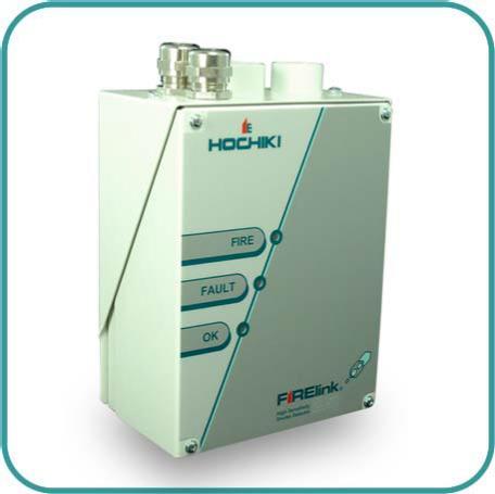
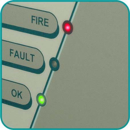
6 Page 6 of 40 FIRElink-25 Installation Manual This symbol appears on the main board of the unit and indicates that the board contains static sensitive components. Suitable anti-static precautions must be taken when handling the board. Hochiki Europe (UK) Limited has taken every care to ensure that FIRElink-25 is as simple to install as possible but in case of difficulty, please contact our Product Support Department to ensure trouble free installation and operation. Hochiki Europe (UK) Limited takes no responsibility for damage or injury occasioned as a result of failing to install or operate the equipment in accordance with these instructions. 1.1 Indicators Fire indicator illuminates when the alarm level has been reached and the appropriate time delays have expired. Fault. Illuminates when the unit has a fault and a fault signal is being sent to the fire alarm panel. OK. Illuminates to show normal operation when there are no faults. The OK lamp will flash during the 15 minute Fastlearn period when the detector is first learning about its environment.
7 FIRElink-25 Installation Manual Page 7 of Inside the Detector Removable terminal blocks (see section 1.3) Filter (see section 8) Addressable programmable interface card (FIRElink-APIC) port (see section 5.3) Detector address DIP switch (see section 5.1) RS232 serial port (see section 5.4)

8 Page 8 of 40 FIRElink-25 Installation Manual 1.3 Detector Terminal Block Connections Normally closed FAULT relay contacts Normally open FIRE relay contacts FIRElink-APIC addressable bus connections for use in conjunction with interface card (see sections and 5.3) RS485 / SenseNET connections (see sections 4.1.4and 5.2) Power supply connections (see section 4.1.3)
.")


9 FIRElink-25 Installation Manual Page 9 of 40 2 Programming the Detector The FIRElink-25 may be programmed from a PC when connected to the detector via a standard 9-pin serial lead connected to the serial port of the computer and the 9 way socket at the base of the detector (see section 7.4, Connecting to a PC ). In order to do this, it is necessary to install the remote control software onto the computer. A copy of the remote control software is contained on a CD-ROM supplied with each detector. Install the software in accordance with the on-screen instructions. To open the software, select Start > Programs > Hochiki > Remote 3.0 The programmable functions are all accessed though the Options > Detector settings submenu or by clicking on the detector button on remote software toolbar as indicated below: The following screen is displayed: This window contains all the programmable functions for the FIRElink-25. To amend one of the programmable functions, go to the relevant tab, make the change and then click OK. This will save the change to the detector s internal firmware. A list and explanation of the various functions is given below, with the functions grouped by the tab under which they appear. 2.1 Time and Date tab It is important that the time and date be set up correctly on the controller s internal calendar/clock because it uses this information to store events in the event log. See section 8, Event log for more details. Unless specially ordered, units are supplied with the correct setting for UK time. This is backed up with a rechargeable battery. Later adjustments to the clock setting should not exceed ± 70 minutes unless a FastLearn is initiated.
10 Page 10 of 40 FIRElink-25 Installation Manual 2.2 Alarm Levels and Delays Tab Alarm Levels - (Level subgroup) The value set in the Fire, Pre-Alarm and Aux functions in the Level subgroup is the relatively scaled bargraph level at which the appropriate alarm is initiated on the detector. The Fire 2 level assigns an absolutely scaled alarm level in % obs/m. The Aux level is set by factory default at level 10 which means that this alarm will occur after the Fire alarm. The default level settings for Pre-Alarm and Fire 1 are 6 and 8 respectively. The default setting for Fire 2 is 20% obs/m Alarm Delays - (Delay subgroup) The alarm delay is the number of seconds that an alarm level has to be continuously sensed before the alarm is initiated. Each alarm level has a programmable delay of between 0 and 90 seconds. The default delay for each alarm level is 5 seconds ClassiFire Override This function has no current use on the FIRElink-25 but is reserved for future expansion purposes Alarm Factor The detector sensitivity is set with this entry, which will also affect the probability of nuisance alarms. 0 = high sensitivity, higher probability, 8 = low sensitivity, lower probability. The default alarm factor is 4. Note: The highest sensitivity setting is suitable for clean, environmentally controlled environments, e.g. semiconductor manufacturing clean rooms where airborne pollutants are kept to an absolute minimum and the least contamination is cause for alarm. Use of this setting in a busy machine shop would lead to relatively frequent nuisance alarms due to the normal variation of atmospheric contamination and a lower sensitivity setting is recommended. It is therefore important that the alarm factor chosen is suitable for the area to be protected. When the appropriate alarm factor for the protected area has been set, nuisance alarms will be reduced to an absolute minimum. The following table gives suggested settings of ClassiFire alarm setting for different locations: Alarm Factor Sensitivity Probability of Nuisance Alarm 0 Extremely High Once per year Semiconductor manufacturing clean room 1 Once per 5 years Computer room 2 Once per 10 years Non-smoking office 3 Once per 50 years Clean factory 4 Medium Once per 1000 years Warehouse Suggested Protected Area 5 Medium Once per 5000 years Warehouse with diesel trucks operating 6 Medium Once per years Warehouse with diesel trucks operating 7 Low Once per years Warehouse with diesel trucks operating 8 Low Once per years Warehouse with diesel trucks operating
11 FIRElink-25 Installation Manual Page 11 of LDD Enable When this function is ticked, Laser Dust Discrimination (LDD ) increases the response time of the detector slightly, whilst greatly reducing the likelihood of nuisance alarms due to dust ingress. LDD may be disabled in very clean rooms for a slightly faster response to smoke by setting this function to unticking the box. This function is enabled by default. NOTE: Disabling LDD is not recommended for areas other than manufacturing clean rooms, due to the increased probability of nuisance alarms in most other operating environments FastLearn Enable If the detector is in FastLearn mode, unticking this box will stop the FastLearn process. Using the function in this way is neither recommended nor supported by Hochiki Europe (UK) Limited. Ticking the box will start a FastLearn at any time. The green OK LED on the front of the detector will flash for the fifteen minutes that it takes for the FastLearn process, and will then change to constant illumination to indicate that the FastLearn is complete. Note: It will take a further 24 hours after the FastLearn for full sensitivity to be reached, unless Demonstration Mode has been initiated (See section 3.10, Demo mode ). It is essential for proper functioning that the detector not be left in Demonstration mode, and that it be allowed to complete the 24-hour learning period. To cancel demo mode, tick this box or power down and restart the detector to initiate FastLearn mode Auto FastLearn Enable When enabled, this function ensures that if the detector is powered off for any reason (e.g. for maintenance or to be moved to a new area), a FastLearn is commenced automatically on power-up. There may be occasions when it is desirable to power down the detector for short periods of time, and it is highly likely that ambient contaminant levels will be the same on power-up. Under these circumstances it may not be desirable that the detector should to go through the whole learning process again. To this end, this function can be unticked before power-down, whereupon it will return to the original settings on power-up. This function is enabled by default ClassiFire 3D If this function is ticked, then the detector will ignore any pre-set time delays in the event of an unacceptably rapid increase in smoke density, thereby minimising response time to 'rapid growth' fires. This function would normally only be used where there were long time delays programmed on the alarm levels. This function is disabled by default Demo Mode Demonstration mode is an operating mode whereby the normal 24-hour learning period is bypassed, so that the detector can reach high sensitivity after only the 15 minute FastLearn period. This can be used so that initial smoke testing and other commissioning can be carried out. However, it must be understood that, since the alarm levels will be based solely upon the sparse data gathered during the FastLearn period, there is a risk of nuisance alarms due to normal variations in ambient smoke levels. For this reason, the detector should not be left in Demo mode for normal use when connected to a fire panel.
12 Page 12 of 40 FIRElink-25 Installation Manual 2.3 Day/Night Switching Tab Day Start / Night Start These values are the times to the nearest hour at which the day/night switching is desired to take place on the detector. Entries are made in 24-hour format, e.g. 19 for 7pm. Day and night switching is intended so that the detector may automatically select a different sensitivity when the protected area is unoccupied and fewer contaminants are being produced. ClassiFire automatically detects the change in smoke level after the protected area is left, and if the time at which this happens is within + 70 minutes of the programmed switchover time it selects the night-time histogram. This means that changes in time setting, for example changing to summer time, may be ignored as the detector will take this into account. The default times for day and night start are 08:00 and 19:00 respectively. NOTE: That if the environment actually becomes more contaminated during the night period for any reason then ClassiFire will adapt to that too, reducing the night-time sensitivity Disable Day / Night Switching If day/night switching is not desirable, the Disable day/night switching box may be ticked to leave the detector permanently in day mode. 2.4 Alarm Actions Tab Remote Functions (Remote Input subgroup) These functions have no current use on the FIRElink-25 but are reserved for future expansion purposes Programmed Isolate When this function is ticked the controller will not generate alarms and will not indicate a fault condition on any fire panel which is connected, e.g. for use during detector maintenance. The Fault light will be illuminated on the detector front panel. The isolated condition will be disabled automatically after 7 days if not manually disabled. This function is disabled by default Latching Alarms When this function box is ticked it requires a reset from the controlling computer to clear an alarm condition. If unticked, the alarm signal is extinguished as soon as the alarm condition ends. This is the factory default setting Latching Faults When this function box is ticked it requires a reset from the controlling computer to clear a fault condition. If unticked, the fault signal is extinguished as soon as the fault condition ends. This is the factory default setting Cascading Alarms Ticking this function box means that only when the detector s controller has gone into Pre-Alarm does the controller start counting down the main Fire delay i.e. the time delays on Pre-Alarm and Fire 1 are cumulative. The Aux alarm is not included in the cumulative delay since it may be set to a higher level than either the Pre-Alarm or Fire 1 levels. This function is enabled by default.
13 FIRElink-25 Installation Manual Page 13 of Device Information Tab Device Type This function is for display purposes only. It shows any special designation for the unit, which will normally be FIRElink Firmware Version This function is for display purposes only. It shows the version number of the fitted firmware chip Run-time Hours This function is for display purposes only. It shows the cumulative total number of hours that the device has run (this is not the time that has elapsed since last power-up, but the sum total of run time since the detector memory was last reset) Watchdog Count The watchdog is a circuit built into the controller that restarts the controller in the event of a failure to function properly. This could be as a result of electrical spikes. This count shows the number of interruptions found. The details of each problem can be found in the event log. See section 6, Event Log for further details Device Text This function has no current use on the FIRElink-25 but is reserved for future expansion purposes. 2.6 Referencing Tab Reference Detector A FIRElink detector may use another detector as a fresh air reference. This function is the address of the detector which will be used as the reference. To set a detector as a reference detector, enter its address as set by its internal DIP switch into this function. This function is disabled by default Reference Enable Ticking this box enables the reference for the detector, if one has previously been allocated in Reference detector (see section 2.6.1). This function is disabled by default Reference Level The value set with this function is the percentage reference signal subtracted from the detector s signal, if a reference device has been allocated. The default value is Reference Back-off This value is the delay time between a build up of pollution being seen by the reference (if used) and the pollution being seen by the detector. The default value is 15.
14 Page 14 of 40 FIRElink-25 Installation Manual 2.7 Flow Monitoring Tab Flow Rate This function is for display purposes only, and shows a value corresponding to the current airflow through the detector Flow High Limit This value is the level above which airflow needs to increase to trigger a fault indication (which may indicate a loose or damaged inlet pipe). Flow low limit and Flow high limit parameters are automatically set up on initial power-up Flow Low Limit This value is the level below which airflow needs to be reduced to trigger a fault reading (which may indicate a blocked pipe). Flow low limit and Flow high limit parameters are automatically set up on initial power-up Flow Fault Delay This feature requires the Remote Control Software version 3.2 or later, available from the Hochiki Europe Technical Support Department (psupport@hochikieurope.com). The default flow fault thresholds on the FIRElink-25 are set to meet the stringent airflow monitoring requirements of EN54-20, with a default flow fault delay of 30 seconds. This may lead to unwanted flow faults being generated when local conditions cause short-term variations in airflow. To help alleviate such issues, the flow fault delay is programmable from 30 to 240 seconds. The flow level needs to be above the high flow threshold or below the low flow threshold throughout the delay period for a fault to be generated. NOTE: When setting the value of this function, it is important to take into account that the control unit (for example, fire panel) may not react immediately to a trouble signal being generated by the detector, and this will add to the total fault response time of the system. The function value must be chosen so that the total time between the detector entering a fault condition and a fault signal being generated by the panel meets the requirements of local or national fire regulations. The maximum allowable response time for EN54-20 compliance is 300 seconds, and that for NFPA 72 compliance is 200 seconds. As an example: in the latter case, if the flow fault delay were set to 180 seconds (within the limit), but the fire panel did not generate a fault indication for another 25 seconds, the total response time of 205 seconds means the system would not comply with the regulations. If documented figures are unavailable for the fire panel reaction time, compliance with reaction time regulations may only be verified by post-installation testing. 2.8 Miscellaneous Tab Access Code This is the access code required to amend programmable parameters. The default code is Once the appropriate code is entered it may be changed here to any four digit number to limit unauthorised access.
15 FIRElink-25 Installation Manual Page 15 of Chart Recording Rate This function controls how frequently the detector and alarm level or flow rates are stored in the FIRElink- 25 s internal chart recorder log. (See section 2.10, Chart Recording ). Setting Type Storage Interval Time per Division on Chart Log 0 Detector Output 1 second 10 seconds 1 Detector Output 5 seconds 50 seconds 2 Detector Output 12 seconds 2 minutes 3 Detector Output 30 seconds 5 minutes 4 Detector Output 1 minute 10 minutes 5 Detector Output 2 minutes 20 minutes 6 Detector Output 5 minutes 50 minutes 7 Detector Output 10 minutes 100 minutes 8 Detector Output 20 minutes 200 minutes 9 Detector Output 50 minutes 500 minutes 10 Flow Recording 1 second 10 seconds 11 Flow Recording 5 seconds 50 seconds 12 Flow Recording 12 seconds 2 minutes 13 Flow Recording 30 seconds 5 minutes 14 Flow Recording 1 minute 10 minutes 15 Flow Recording 2 minutes 20 minutes 16 Flow Recording 5 minutes 50 minutes 17 Flow Recording 10 minutes 100 minutes 18 Flow Recording 20 minutes 200 minutes 19 Flow Recording 50 minutes 500 minutes In the above table the shaded cells indicate flow rate recording whilst the white cells indicate detector and alarm level recording. At the slowest recording rate, one month of data can be recorded. The factory default setting is Separator Condition The value given at this function is the efficiency rating of the dust separator element in the detector as a percentage of the efficiency of a clean separator. A new element will give a reading of 99 in this function. When the efficiency has decreased to 80%, the Fault indicator LED will illuminate and the event log will show Separator renew. NOTE: Fitting a new element will reset this figure to Separator Change Date This function defaults to --, which means that a separator fault will only appear when the efficiency decreases to 80% (see 2.8.3, Separator Condition ). However, a date may be entered into this function
16 Page 16 of 40 FIRElink-25 Installation Manual to allow for a scheduled maintenance period. The detector will then generate a separator fault at the planned time regardless of the condition of the separator, although degradation of the separator to below 80% efficiency before this date will override this. See section 8, Maintenance for further details Factory Default Enabling this function will reset each programmable function to the default value indicated in the text, where a default setting is specified. It will also put the detector into FastLearn mode, regardless of whether or not Auto Fastlearn is enabled (see section 2.2.7). This ensures that the flow setups and alarm thresholds are optimised to the detector s working environment after resetting. It should be noted that where a ClassiFire alarm factor other than the default is required for the protected area, this will need to be re-entered. Section gives details of the ClassiFire alarm factors. 2.9 Other Remote Software Features Reset If latching alarms (see section 2.4.3) or latching faults (see section 2.4.4) are enabled, the relevant alarm or fault warnings will remain on the detector front panel LEDs and controlling unit until a reset is performed. If using SenseNET software, individual detectors can be reset (refer to the SenseNET User Guide for details). In the remote software, a global reset is available which resets all detectors on the SenseNET loop, or a single stand-alone detector. To perform a reset, either select the menu options Options > Global Reset or click the button on the toolbar as indicated below: Histogram Screen The histogram screen shows various aspects of the detector function. To enter the histogram screen, either select the menu options View > Histogram Viewer, or click the button on the toolbar as indicated below: The following screen is displayed:
.")
17 FIRElink-25 Installation Manual Page 17 of 40 Smoke Density histogram Alarm flags There are two types of smoke density histogram; one shown in blue (the fast histogram) which updates every 15 minutes, feeding information to the long-term slow histograms (which appear in yellow). These set the detector sensitivity based on the ambient smoke conditions and it takes 24 hours for the two slow histograms (the day and the night histograms) to complete their learning phase (see section 2.2.6). Detector sensitivity is based on the fast histogram during FastLearn and is thereafter based on the currently active slow histogram. However, although the positions of the alarm flags are based on the slow histogram, sudden changes in smoke density are picked up by the fast histogram so that early warning is given. Sensitivity: The current absolute sensitivity of the detector in percentage obscuration per metre (% obs/m) Mean: The current mean value of smoke density, taken from the currently active histogram and given as a percentage of full scale deflection. Variance: The spread of data in the currently active histogram and given as a percentage of full scale deflection. FastLearn: If the detector is currently in FastLearn mode, this will show the number of minutes remaining in the FastLearn period. When this period has elapsed it will read OFF. Alarm factor: This is the ClassiFire alarm factor (see section 3.5, Alarm factor ) Day/night: This indicates the currently active slow histogram Alarm levels: These figures give the position of the various alarm flags in terms of a percentage of full scale deflection. Detector output: This shows the real-time variation in background smoke levels in terms of a percentage of full scale deflection.

18 Page 18 of 40 FIRElink-25 Installation Manual 2.10 Chart Recording The chart recording function shows how smoke density in the protected area has varied over time. The chart may be downloaded to disk or printed out from a connected printer. To access the chart log, select the menu options View > Chart Recording or click the button on the toolbar as indicated below: The following screen is displayed: The red trace is the current alarm level and the black trace is the detector output. By moving the cursor along the chart, the Chart information window (shown at the bottom left) updates to show the date and time, detector level and alarm level of the relevant period. The File menu option in the chart recording window allows the chart recording to be saved to disk or printed to a connected printer, and allows a previously saved chart recording to be loaded. Chart recording files have the extension.rcw Load / Save Function Settings Where a custom set of programmable function settings is commonly used, these may conveniently be saved to or loaded from disk. To open a detector function settings (.dfs) file, select the menu options File > Open or click on the button on the toolbar as indicated below: A file browser window will be displayed, click on the List files of type drop-down box and select Detector settings (*.dfs) as indicated below:

19 FIRElink-25 Installation Manual Page 19 of 40 A list will appear of all detector settings files stored on the current drive. As a special case, if desiring to recall the factory default settings, there is a file named default.dfs in the remote2k directory. Loading this file will reset the detector to the factory default.


20 Page 20 of 40 FIRElink-25 Installation Manual 3 Design Limitations FIRElink-25 is intended to provide LOCALISED incipient fire detection only. This means that it is suitable for the substantial range of applications typified by; small non-compartmentalised rooms, warehouse racking, or pieces of electronic or electromechanical equipment where it is desirable to achieve individual incipient fire reporting. In compartmentalised rooms, each compartment would normally use individual FIRElink-25 detectors. This product employs a very low-power aspirator and the aspirating capability of the FIRElink-25 detector is limited accordingly. FIRElink-25 is NOT intended to protect large areas, or to sample from areas where there may be any difference in airflow rates or pressure differentials. Application of FIRElink-25 in these circumstances is not recommended. If detection in environments conforming to these descriptions is required, alternative versions of FIRElink products should be used. Maximum recommended sampling pipe length is 50 metres in STILL AIR. In areas or applications where the external airflow rate is greater than 1 metre per second, the maximum sampling pipe length is reduced to 25 metres. Although by no means essential, it must be recommended that if in doubt, PipeCAD be used to ensure that transit times, balance of suction and individual sampling point sensitivity are within desired limits. Sampling pipes must have capped ends. The end cap should be drilled with a hole normally between 4 or 5mm diameter and free from burrs. Sampling holes should normally be 3-4mm diameter or as calculated by PipeCAD, and free from burrs. Each pipe run should not have more than 10 holes (including the end cap hole). Pipe transit time from the furthest sampling hole from the detector must not exceed 120 seconds and an approved type of pipe must be used for installations conforming to LPCB requirements. It is strongly recommended that the smoke transit time from the furthest sampling hole be checked during commissioning tests. Capillary Remote Sampling Points may be used in place of sampling holes. FIRElink-25 is supplied with a Piped Exhaust type Docking Station (see illustration A). This is primarily intended to allow the FIRElink-25 detector to sample from areas which may be at different air pressure to the detector location. Typical uses are for air-duct sampling and allowing the installation of the detector in under-floor or ceiling voids or when sampling from pieces of computer related equipment. A Above Ceiling Sampling with exposed detector.

21 FIRElink-25 Installation Manual Page 21 of 40 B Above Ceiling Sampling with detector mounted in ceiling void. 3.1 System Design Simple designs with short sampling pipes produce the best results. Complex sampling pipe runs should be avoided with the FIRElink-25 detector. The use of T branch-pipes is not recommended. To assist in design and to verify system performance, it is advisable to use the FIRElink PipeCAD sampling pipe modelling software. Always locate the sampling points in positions to which smoke may reasonably be expected to travel. Do not expect ceiling mounted sampling points to operate satisfactorily if air flow from air-conditioning systems keeps the cool smoke from an incipient fire reaching from reaching ceiling level. In this instance it is usually better to locate the sampling pipe directly in the airflow (for example across the return air register of an air conditioning unit). There is no substitute for carrying out smoke tests prior to installation of pipe work to indicate suitable sampling point location. No more than ONE Air Handling Unit may be protected with one FIRElink-25 detector. In this application, ensure that the sampling pipe is raised clear of high velocity air in the immediate vicinity of the air intake grille on stand-off posts as shown below:

22 Page 22 of 40 FIRElink-25 Installation Manual 3.2 EN54-20 Compliance The installation must be designed using PipeCAD software, which is provided free on the CD shipped with each detector. After designing the installation including pipes, endcaps and sampling holes, enter the detector type in the Type drop-down list in Options Calculation options. Select Options Calculate or click on the calculator icon. The software will prompt you to choose from Use set hole sizes Best flow balance and Max. permissible transit time. Select the appropriate option and click OK. The results for each pipe ( View Results ) show calculations for each sampling hole on the pipe with the nearest to the detector at the top of the screen, and the endcap hole at the bottom. Transit time shows the smoke transit time to the detector from each sampling hole. For EN54-20, this must be below 120 seconds from every hole. The column headed Hole sensitivity % obs/m shows the predicted sensitivity for each hole. For the installation to comply with EN54-20, each sampling hole must be no less sensitive than 0.31% obs/m.* The calculation can be further refined by leaving a working detector in the protected area for at least 24hrs at the intended alarm factor for the installation (this could be done before or after installation). The detector sensitivity can be read from the Sensitivity figure on the histogram screen of the Remote software supplied with each detector. Enter this figure into the PipeCAD calculation under Options Calculation options, Detector sensitivity. Clicking on OK will update the hole sensitivities to the figure expected for the actual layout. Commissioning and periodic system tests must involve smoke tests to verify that the system performs as expected and enters Fire 1 alarm within 120 seconds from the farthest hole. The detector sensitivity must also be inspected to ensure it has not radically fallen from the installed figure. If it has changed for any reason. the new figure must be re-entered into PipeCAD and the recalculated hole sensitivities must be confirmed to be within the class limits shown above. The settings of a compliant system should be recorded, as it is possible by changing certain programmable functions to make the system non-
23 FIRElink-25 Installation Manual Page 23 of 40 compliant. If functions are changed, it is recommended that the system is retested if continuing compliance is in any doubt. *The results should be verified at installation by entering the installed detector's Fire 1 sensitivity (as indicated in the remote software histogram screen) into the PipeCAD Options/Calculation options/detector sensitivity field and recalculating the layout results.
24 Page 24 of 40 FIRElink-25 Installation Manual 4 Installation Before installing the detector the local standards for installation of aspirating detection systems must be consulted as these standards differ throughout the world. Specific advice for one country may not be applicable to another. The following is a brief set of guidelines on installing detectors: The detector will normally be mounted at a level where there is easy access to the unit for configuration and programming. The exhaust air from the unit must not be impeded in any way. If the unit is mounted in a different air pressure from where the air is being sampled (for example an air duct), then a pipe must be taken from the exhaust port back to the same air pressure zone as the sampling holes. Sampling holes should be free from burrs and swarf. All signal cables must be screened and must be of a suitable type. The specific type of cable will normally depend upon the local fire regulations. The unit must not be placed in areas where either the temperature or humidity is outside the specified operating range. The unit should not be placed in close proximity to any equipment expected to generate high Radio Frequency levels (such as radio alarms) or units generating high levels of electrical energy (such as large electric motors or generators). In order for the installation to conform to EN54-20, pipes must conform at least to EN Class Docking Station The basic principle behind installation of the FIRElink-25 is that all wiring and pipe-work is installed using a docking station. This is a convenient feature which means that the detector can be dismounted or replaced without disturbing any wiring or installed pipe-work.

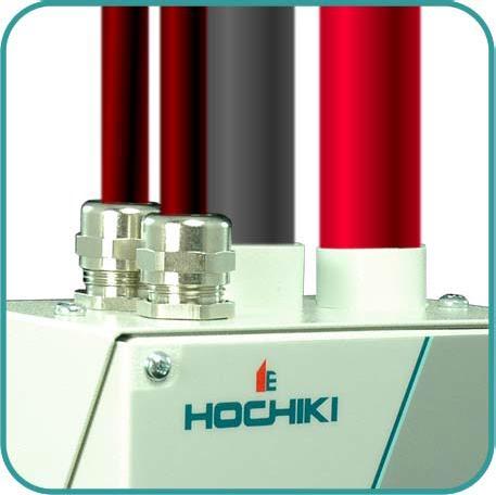
25 FIRElink-25 Installation Manual Page 25 of 40 Piped Exhaust Docking Station Mechanical Installation The docking station is connected to the installed sampling pipe-work and fixed to the wall or mounting surface using 3 off screws of a type appropriate to the mounting surface. Ensure that the sampling and/or exhaust pipes are securely seated in the pipe ports before fixing. If using a piped exhaust docking station be sure that the sampling and exhaust pipes are fitted into the relevant ports as shown in section Electrical Installation The FIRElink-25 detector is supplied with removable terminal blocks (See illustrations in Section 0). These are simply removed from their sockets by lifting them up at right angles to the circuit board. Take note of the orientation of each terminal block and its function before removing it. It may also be beneficial to mark the connection wires with suitable identification labels or coloured rings to aid in the connection process. NOTE: All connections should be made with the power turned off Power Supply Connections The power supply cable should be of screened type and should be led through the metal cable gland provided, leaving about 35mm of the cable extending from the bottom of the cable gland. Depending on the type of cable used, it may be necessary to increase the diameter of the cable with sleeving or insulating tape to ensure that the cable is firmly held when the cable gland is fully tightened. Remove the detector cover by unfastening the four screws at the front of the unit and detach the power supply terminal block. This is at the top left with the detector held with the serial port at the bottom of the unit. NOTE: Be aware of the orientation of the terminal block. Connect 0V and +24VDC to the 0V and 24V screw terminals respectively. Connect the screen wire to the earth stud on the docking station and connect a second wire from the Earth terminal to the docking station earth stud. The picture in Section 4.1 shows the location of the earth stud. Fix the earth wires in place with the nuts provided Signal Connections To connect the signal wire, lead a suitable wire type (RS485 cable 9841, 120 ohm screened twisted pair or equivalent) through the second cable gland and tighten it into position with about 35mm of cable from the bottom of the cable gland. Remove either the three-way terminal block next to the power supply socket if connecting the detector to a SenseNET system, or the four-way Bus terminal block if connecting the detector to an alarm panel in conjunction with the FIRElink- APIC addressable programmable interface card (see section 5.3). FIRElink-APIC RS485/SenseNET Address Terminals Terminals For example, in a SenseNET system using screened cable connect the screen wire(s) to the SCN terminal, Bus A wire(s) to the A terminal and Bus B wire(s) to the B terminal. If the detector is in the middle of a SenseNET chain, with input and output connections, it may be more convenient to link the common Bus A, Bus B and screen wires to single A, B and screen wires for linking to the terminal block.

26 Page 26 of 40 FIRElink-25 Installation Manual The following illustration shows the power and signal connections to the docking station for connection to a single SenseNET cable: Power Supply Screen Wire to Earth Stud SenseNET/RS485 Bus A Wire SenseNET/RS485 Bus B Wire Power Supply 0V Wire SenseNET/RS485 Bus Screen Wire Wire from "Earth" Terminal to Earth Stud Power Supply +24V Wire 4.2 Final installation Once the power and signal connections are made slide the detector body up into the docking station and fasten it into position using the M4 pan head screws provided. Slot the power and signal terminal blocks into the relevant sockets on the detector PCB (they will only click fully home in the correct orientation) and replace the detector cover using the four M3 pan head screws provided. NOTE: The detector is designed solely for operation with the front cover securely fitted using all four fixing screws. Removing the detector is simply the reverse of this process, leaving the pipe-work and wiring connections installed in the docking station.

27 FIRElink-25 Installation Manual Page 27 of 40 Dock Fixing Screws Cover Fixing Screws Cover Fixing Screws


28 Page 28 of 40 FIRElink-25 Installation Manual 5 Interfacing Because of the flexible nature of the FIRElink-25 detector and the many possible configurations, there are many options for interfacing the detectors to the Fire Panel. These include many third party interfaces available from various manufacturers. Because of this, it is not possible to give a complete list of all interfacing methods but the following pages will give details of the most common methods that are likely to be used. 5.1 Setting the Detector Address In order to identify itself to the PC Command Module or fire panel, each detector needs to have a unique address ranging from 1 to 127. The detector address is simply set on the red DIP switch SW1 at the top left of the opened detector on the main circuit board. The switch settings are on for 1 and off for 0, and the detector address is set as a 7-bit binary code (switch 8 equates to a value of 128 and so is outside the usable address range). An example is shown below. The address equates to in binary, or (1 x 1) + (1 x 2) + (0 x 4) + (0 x 8) + (0 x 16) + (1 x 32) + (1 x 64) + (0 x 128) = 99. The full range of available addresses and their relevant switch settings are shown below:

29 FIRElink-25 Installation Manual Page 29 of Connecting a FIRElink-25 to a SenseNET/RS485 Detector Network Up to 127 detectors may be linked in a single SenseNET bus, supporting a total length of wire between adjacent detectors of up to 1.2km. In the above example, two FIRElink-25 detectors are linked into a 127-detector bus with a Command Module and a number of other FIRElink detectors. It will be noted that whereas the FIRElink-400 units have two input / output buses (1A / 1B and 2A / 2B), the FIRElink-25 has only a single such bus (A / B) and therefore each bus terminal has an input and an output wire, compared with a single wire in each terminal in the FIRElink-400. For this reason, it may be easier to join the input and output wires for each bus and screen connections together and to solder or crimp a single wire or connecting ferrule to each wire pair so that they are easier to fit into the screw terminals. If this is done it is recommended that bare wire joints be insulated to prevent possible shorting of the data bus, which will cause a drop-out of data on the SenseNET bus. In the above example, there could be a total length of RS485 cable of up to 1.2km between the Command Module and Detector 3, since these are all on a single bus. However, Detector 3 is a FIRElink-400 which has a second communications bus (RS485 bus 2) and an RS485 repeater. This allows a further total of 1.2km of cable until the next FIRElink-400 in the RS485 loop. In the above example, if detectors (not shown) were all of the FIRElink-25 type then the total length of wiring between detectors 3 and 127 would be limited to 1.2km. However, each additional FIRElink-400 detector wired up using both RS485 buses would allow an additional 1.2km of cabling to be added to the RS485 loop. 5.3 Connecting a FIRElink-25 to an addressable Fire Panel An Addressable Programmable Interface Card (FIRElink-APIC) may be used to decode detector information and to relay this to a Fire Panel. The FIRElink-APIC is fitted to the four mounting studs on the FIRElink-25 PCB using the supplied screws as shown below:
 and the BUS L2 and H2 (bus 1 input and output) terminal connectors shown in Section 4.")
30 Page 30 of 40 FIRElink-25 Installation Manual FIRElink-APIC Mounting Studs FIRElink-APIC Address Switches (x 2) FIRElink-APIC Interface Connection The connections to the Fire Panel are made using the BUS L1 and H1 (bus 1 input and output) and the BUS L2 and H2 (bus 1 input and output) terminal connectors shown in Section The only settings that need to be made are on the FIRElink-APIC address DIP switches. The start loop address Is entered on SW1 and the end loop address on SW2. In the case of a single FIRElink-25 the start and end addresses will be the same. NOTE: The detector address on the SenseNET loop and the Fire Panel addressable protocol address are the same, in other words, no address translation is performed. Some protocols may not support all the available alarm levels and fault reporting is usually a general fault with no detailed fault information. Please consult the specific FIRElink-APIC documentation for more information.
31 FIRElink-25 Installation Manual Page 31 of Connecting to a PC To connect a single stand-alone detector to a PC, connect the PC s serial port directly to the detector s 9- way RS232 port, which is situated on the bottom surface of the detector case. Connections for this cable are shown below:

32 Page 32 of 40 FIRElink-25 Installation Manual 6 Event Log An event is defined as a change to any programmed function a signal received from an external controller such as the remote software, FIRElink-APIC or SenseNET a detector output level meeting or exceeding the Pre-Alarm, Aux, Fire 1 or Fire 2 alarm thresholds a fault condition such as a flow or separator fault start of day / night operation demonstration mode start / stop FastLearn start / stop Power on or off The detector stores an internal log of the last 200 events, and this can either be viewed on a PC screen or downloaded to disk by use of the remote control software. When the event log is full (200 events are stored) and a new event occurs, the oldest event in the log is deleted (First-In, First-Out). To download the event log, connect a PC to the detector serial port and run the remote software. Either select the menu options View > Event Log or click on the event log symbol as indicated below: The following screen will be displayed: This shows the time and date of each event stored in the log along with its general description. The buttons at the bottom of the screen allow control over the input and output of the log.

33 FIRElink-25 Installation Manual Page 33 of 40 Open: Save As: Print: Filter: opens a previously saved event log. Event logs have the file extension.evl. saves the current event log as a.evl file with a user defined name. prints the event log to a connected printer. clicking on this option displays the following screen: This allows the user to limit the information printed or viewed on the PC screen. For example the user might wish to concentrate on alarm events only. To do this, click on None, which unticks all boxes, and then click on Alarms. To tick all the boxes, tick All. Any or all of the event categories may be selected or deselected as desired.
34 Page 34 of 40 FIRElink-25 Installation Manual 7 Commissioning Before commissioning the detector the local standards of aspirating detection systems must be consulted. These standards differ widely throughout the world and specific advice for the market in one country may not be applicable to another. Commissioning strategy will initially depend upon the environment in which the detector is installed. For instance, the test for a computer room (which should be a relatively clean environment) would be very different from, say, a flour mill, which would probably have a high level of airborne particulate content. A widely accepted standard for computer rooms/edp areas is British Standard BS6266, equipment overheating at a stage well before combustion. To perform the test electrically overload a 1 metre length of PVC insulated wire of 10/0.1mm gauge for one minute using an appropriate power supply. The detector has two minutes from the end of the wire burn to give an alarm indication. For areas with higher levels of background particulate matter testing methodology would be similar to that of standard point detectors. 7.1 Commissioning Checklist The following brief checklist allows quick setup of the detector. This procedure will be adequate for most standard installations. 1. Before powering up the detector, visually check all cabling to ensure correct connection. If wire identification is not immediately clear (for example, by use of different coloured wires or wire identification sleeves) an electrical check should be made. Any damage caused by misconnection of the detector is not covered by warranty. 2. Power up the unit and connect to a PC and set the address switches on the detector board (see section 5.1) and FIRElink-APIC board if applicable (see section 5.3). 3. Verify that the time and date are correct (see section 2.1) 4. Set an appropriate alarm factor for the protected environment. The detector will perform a FastLearn for the new alarm factor. (see section 2.2.6) 5. Whilst the detector is still in FastLearn mode set the detector into demonstration mode (see section 3.10). NOTE: Aerosol-type synthetic smoke sources should not be used to test the response of the detector as these may leave acidic residues which could cause damage to the unit. 6. Wait for the FastLearn to finish and the flashing OK LED indicator will finish and perform any necessary smoke tests, ensuring that the detector reacts appropriately (within 120 seconds for LPCB compliance), and let the smoke fully dissipate. 7. Perform another FastLearn, this time not putting the detector into demonstration mode. The detector will generate no alarms during the 15 minute FastLearn period, and after this the detector will operate at a reduced sensitivity for 24 hours whilst ClassiFire acclimatises to the protected environment and sets up appropriate day and night sensitivity settings.
 cloth. Do not use solvents as these may mar the front panel label.")
35 FIRElink-25 Installation Manual Page 35 of 40 8 Maintenance FIRElink-25 is a very low maintenance detection system. If required, external cleaning of the unit should be performed using a damp (not wet) cloth. Do not use solvents as these may mar the front panel label. The only part that may require field replacement during servicing is the dust separator assembly. The dust separator condition can be checked using the Dust Separator test in the Miscellaneous tab of the remote software Detector settings screen (see section 2.8.3) which gives a percentage reading of dust separator efficiency. When this level drops to 80% the detector will signal a fault and the dust separator will need replacing. To replace the filter, simply remove the front cover and pull the filter out from the main unit. Slide the replacement filter in so that the Direction of flow arrow printed on the carton duplicates that on the Direction of flow label beside the filter slot. As dust contained in the dust separators may expose maintenance personnel to a Nuisance Dust hazard as defined by the Control of Substances Hazardous to Health (COSHH), it is strongly recommended that suitable masks and protective clothing be worn when changing filters. Used separators are not intended for re-use and should be disposed of. 8.1 Diagnostics The remote control software includes a diagnostic function which carries out a number of checks to verify the correct functioning of the detector. A good time to run these tests is as a part of planned maintenance. To call up diagnostic mode, select the menu options View > Diagnostics or click on the symbol indicated below: The following message will be displayed: The software will then scan the loop for up to 127 detectors. For a single detector, wait until the first detector has been identified and the window indicates that it is scanning for Detector 2, then press the Cancel button. The following window is displayed:

36 Page 36 of 40 FIRElink-25 Installation Manual Click on the list entry to highlight it and click on the Diagnostics button. The software will then commence the system tests. During the Aspirator and flow test, the detector fan will suddenly slow down, but this is a normal part of the test. When the test has finished and no problems have been found, the following screen is displayed: If any problems were found during the diagnostic tests, the nature of the fault will be indicated in the Status column. Scan: Reads in the status of all connected detectors. Read Button: This brings up a display of the detector output and flow rate which updates in real time. Relays: Save As: Print: Brings up a screen allowing the function of the volt-free Fire and Fault LEDs to be tested with the aid of a continuity meter or other tester. The Fire relay contacts are open in normal operation and will close on test. The Fault relay contacts operate on a Fail-safe basis and are held closed in normal operation. They will therefore open on test. Saves the summary list of scanned detectors and their status as a text (.txt) file. Prints the summary list to a connected printer.
FIRElink-100 Air Sampling System INSTALLATION MANUAL
 FIRElink-100 Air Sampling System INSTALLATION MANUAL Page 2 of 40 FIRElink-100 Installation Manual This manual details the installation of: FIRElink-100 Air Sampling Detector If you have any queries regarding
High Sensitivity Smoke Detector
 High Sensitivity Smoke Detector Installer s Handbook LM 80022 Issue 9 WWW.UKPANELS.COM Introduction 3 1. Indicators 4 2. Inside the Detector 5 3. Programming the Detector 7 4. Other remote software features
High Sensitivity Smoke Detector
 High Sensitivity Smoke Detector Installer s Handbook LM 80022 Issue 14 Introduction 3 1. Indicators 4 2. Inside the Detector 5 3. Programming the Detector 7 4. Other remote software features 15 5. Design
High Sensitivity Smoke Detector
 High Sensitivity Smoke Detector Installer s Handbook LM 80024 Issue 10 Introduction 3 1. Indicators 4 2. Inside the Detector 5 3. Programming the Detector 7 4. Other remote software features 15 5. Design
High Sensitivity Smoke Detector
 High Sensitivity Smoke Detector Installer s Handbook LM80004 Issue 7 Contents page Introduction 3 1. Types of detector 4 2. Controls and indicators 8 3. Programming the unit 10 4. Sampling pipe design
LM80031 Issue H. Installer s Handbook
 LM80031 Issue H Installer s Handbook Index Introduction Page 3 0832 Kidde Products Limited Unit 2 Blair Way Dawdon City: Seaham, County Durham SR7 7PP UK 09 0832 CPD 1312 EN 54 20:2006 Aspirating smoke
Stratos Micra 10 Aspirating Smoke Detector Installers Handbook
 0 Stratos Micra 10 Aspirating Smoke Detector Installers Handbook P/N 10-3519-505-MC10-01 (EN) ISS 15OCT15 Copyright Contact information 2015 UTC Fire & Security. All rights reserved. For contact information,
LaserSense 10 Aspirating Smoke Detector Installers Handbook
 LaserSense 10 Aspirating Smoke Detector Installers Handbook P/N 10-3519-505-LM10-04 ISS 02JUN16 Copyright Trademarks and patents Manufacturer 2016 UTC Fire & Security. All rights reserved. LaserSense 10
LaserSense HSSD-2 Aspirating Smoke Detector Installers Handbook
 LaserSense HSSD-2 Aspirating Smoke Detector Installers Handbook P/N 9-14565 (EN) REV 02 ISS 11ABR13 Copyright Manufacturer Certification Contact information 2013 UTC Fire and Security. All rights reserved.
AIR-Intelligence TM ASD-160H Aspirating Smoke Detection System
 P/N 33-308100-001 June 2009 AIR-Intelligence TM ASD-160H Aspirating Smoke Detection System Design, Installation, Operation, and Maintenance Manual FOREWORD This manual, P/N 33-308100-001, is to be used
AIR-Intelligence TM ASD-320 Aspirating Smoke Detection System
 P/N 33-308100-002 June 2009 AIR-Intelligence TM ASD-320 Aspirating Smoke Detection System Design, Installation, Operation and Maintenance Manual FOREWORD This manual, P/N 33-308100-002, is to be used
LaserFOCUS VLF-250 Engineering Specification
 Vision Fire & Security LaserFOCUS VLF-250 Engineering Specification May 2004 Part Number 20296 LaserFOCUS VESDA 2 VESDA LaserFOCUS Contents Scope...4 Description...4 General...4 Approvals...4 Codes, Standards
Aspirated Smoke Detectors
 Safety Security Certainty LaserSense Aspirated Smoke Detectors We listened to you Aspirated air sampling technology Aspirated smoke detection is a method of smoke detection where the air from the protected
Laptop / PC Programming Manual
 Laptop / PC Programming Manual Doc. # Fire PC Program rev B 01.07 This Document is property of Evax Systems, Inc. The Evax Fire Solutions Programmer Components 2 1.0 System Setup 4 1.1 Interface Setup
AIR-Intelligence Remote Configuration Software
 P/N 33-308100-004 September 2009 AIR-Intelligence Remote Configuration Software User s Guide FOREWORD Note: This Manual, P/N 33-308100-004, is to be used by qualified and factory-trained personnel, knowledgeable
ViewMatrix. Software for Online Monitoring & Control of Matrix2000 Conventional Fire Alarm Panels. Version: 2.0 Revision: 0.1
 ViewMatrix Software for Online Monitoring & Control of Matrix2000 Conventional Fire Alarm Panels Version: 2.0 Revision: 0.1 CONTENTS 1. Introduction...3 2. Keyboard...5 2.1 POWER indication - Normal Operation...5
AnaLASER II Detector. Protection Systems. A UTC Fire & Security Company. High-Sensitivity Smoke Detector (HSSD ) FEATURES DESCRIPTION
 FEATURES DESCRIPTION") AnaLASER II Detector High-Sensitivity Smoke Detector (HSSD ) F-89-250 FEATURES Air Sampling Smoke Detector for Early Warning Applications Two Versions Available: Standard Detector and Ultra Detector STANDARD
AnaLASER II Detector High-Sensitivity Smoke Detector (HSSD ) F-89-250 FEATURES Air Sampling Smoke Detector for Early Warning Applications Two Versions Available: Standard Detector and Ultra Detector STANDARD
HART XL High Sensitivity Smoke Detection
 High Sensitivity Smoke Detection The Hart XL High Sensitivity Smoke Detection system (HSSD) is an aspirating fire detection system designed to give very early indication of an incipient fire condition.
FAAST LT SET-UP AND TROUBLESHOOTING GUIDE. CONTENTS Introduction...1 Wiring up a FAAST LT unit...1. Setting the Fan speed...7
 FAAST LT FIRE ALARM ASPIRATION SENSING TECHNOLOGY SET-UP AND TROUBLESHOOTING GUIDE CONTENTS Introduction....1 Wiring up a FAAST LT unit...1 Power connections and supervision 1 Sounder EOLs 1 Programmable
False Alarm Management
 False Alarm Management This document is intended only for fire system professionals who are already experienced in the selection and positioning of fire detectors. Whenever you apply any False Alarm Management
Simplex Panel Interface Guide
 Simplex Panel Interface Guide February 2016 SATEON Software Integrations Simplex Panel Interface Guide Issue 1.0, released February 2016 Disclaimer Copyright 2016, Grosvenor Technology. All rights reserved.
ZX1e ZX2e ZX5e. Document No Issue 01 user manual
 ZX1e ZX2e ZX5e Document No. 996-130 Issue 01 user manual MORLEY-IAS ZX2E/ZX5E Fire Alarm Control Panels Table of Contents 1 INTRODUCTION... 4 1.1 NOTICE... 4 1.2 WARNINGS AND CAUTIONS... 4 1.3 NATIONAL
Halton SAFE / 7.14 user guide and installation instructions
 Halton SAFE / 7.14 user guide and installation instructions VERIFIED SOLUTIONS BY H A LTO N Enabling Wellbeing Table of contents 1 System description 3 2 User Accounts 4 3 Main menu 7 3.1 Main menu - Change
Interactive Fire Control Panel IFS7002 four signal loops Instruction Manual
 Interactive Fire Control Panel IFS7002 four signal loops Instruction Manual Revision 6/01.17 Contents 1. Introduction... 6 2. Terminology... 6 3. Function... 8 4. Technical data... 8 4.1. Physical configuration...
IMPORTANT. PLEASE NOTE: The infrared beam path MUST be kept clear of obstructions at all times!
 USER GUIDE English IMPORTANT PLEASE NOTE: The infrared beam path MUST be kept clear of obstructions at all times! Failure to comply may result in the Detector initiating a Fire or Fault signal. Contents
E N G L I S H FIRE ALARM ASPIRATION SENSING TECHNOLOGY QUICK INSTALLATION GUIDE STAND-ALONE FAAST LT MODELS FL0111E FL0112E FL0122E. 367 mm.
 E N G L I S H FIRE ALARM ASPIRATION SENSING TECHNOLOGY QUICK INSTALLATION GUIDE STAND-ALONE FAAST LT MODELS FL0E FL0E FL0E mm mm 0 mm DESCRIPTION The LT FL0 Series is part of the Fire Alarm Aspiration
HART XL High Sensitivity Smoke Detection
 High Sensitivity Smoke Detection Hart XL High Sensitivity Smoke Detection (HSSD) TM is a smoke detection system that is simple to install, commission, service and use yet remains brilliantly capable in
Consultant Specification AGILE Wireless Fire Detection System
 Contents Scope of Work... 2 The EN54 Part 2 & 4 Fire System... 2 Standards... 2 Wireless Intelligent Photoelectric Smoke Detector Specification... 4 Wireless Intelligent Thermal Heat Detector Specification...
Control Panel User Guide
 Fire Detection & Alarm System Control Panel V4.14 Control Panel User Guide (TO BE RETAINED BY USER) 26-0397 Issue 6 Fike s policy is one of continual improvement and the right to change a specification
This is to certify that the optical output of the: SENSORNET LR-DTS Temperature Sensing System: (Variants Mark 1, Mark 2a and Mark 2b)
") Optical Services Ltd. This is to certify that the optical output of the: SENSORNET LR-DTS Temperature Sensing System: (Variants Mark 1, Mark 2a and Mark 2b) Meets the requirements stated in IEC 60825-1:2001
Optical Services Ltd. This is to certify that the optical output of the: SENSORNET LR-DTS Temperature Sensing System: (Variants Mark 1, Mark 2a and Mark 2b) Meets the requirements stated in IEC 60825-1:2001
FIRERAY 5000 range USER GUIDE
 FIRERAY 5000 range USER GUIDE 0044-003-04 IMPORTANT PLEASE NOTE: The beam path MUST be kept clear of obstructions at all times! Failure to comply may result in the Detector initiating a Fire or Fault signal.
Instruction manual MTL process alarm equipment. October 2016 CSM 725B rev 2 MTL RTK 725B. Configuration Software Manual
 Instruction manual MTL process alarm equipment October 2016 CSM 725B rev 2 MTL RTK 725B Configuration Software Manual SECTION 1 - INTRODUCTION... 5 Basic Requirements... 5 SECTION 2 - SOFTWARE INSTALLATION...
OVEN INDUSTRIES, INC.
 OVEN INDUSTRIES, INC. OPERATING MANUAL Model 5C7-252 TEMPERATURE CONTROLLER With PLC Inputs Introduction Thank you for purchasing our controller. The Model 5C7-252 is an exceptionally versatile unit and
VESDAnet Interface Card Product Guide. Document Number: 10672_05 Part Number: 30071
 VESDAnet Interface Card Product Guide Document Number: 10672_05 Part Number: 30071 Xtralis VESDA VESDAnet Interface Card Product Guide Intellectual Property and Copyright This document includes registered
Aspirating smoke detection
 Aspirating smoke detection Award winning products, ground-breaking technology A UTC Fire & Security Company About us AirSense the company AirSense Technology is a market leader in the design and manufacture
Control Panel User Guide (TO BE RETAINED BY THE USER)
") Fire Detection & Alarm System Control Panel V3 (Suitable for Quadnet control panels from V2.00) Control Panel User Guide (TO BE RETAINED BY THE USER) 26-0585 Issue 7 Fike s policy is one of continual improvement
Fire Detection & Alarm System Control Panel V3 (Suitable for Quadnet control panels from V2.00) Control Panel User Guide (TO BE RETAINED BY THE USER) 26-0585 Issue 7 Fike s policy is one of continual improvement
Intelligent Security & Fire Ltd
 Product Data Sheet Mx-4000 Series User Manual MX-4100, MX-4200, MX-4400, Mx-4400/LE & Mx-4800 Fire Alarm Control Panels The operation and functions described in the manual are available from Software Versions
Replaceable LED modules. Sleep or unattended mode. Auto-silence and auto-acknowledge
 Replaceable LED modules 11 Alarm Sequences as per ISA-18.1 standard Each channel/window fully field programmable RS232 or RS485 MODBUS-RTU communication Repeat relay for each window and multifunction relays
RESET + Password Enter (During Auto Speed Procedure) Maintenance Timeout or after TEST + RESET + DISABLE (No Need for Device to Initialize)
 Maintenance Timeout or after TEST + RESET + DISABLE (No Need for Device to Initialize)") FAAST LT FIRE ALARM ASPIRATION SENSING TECHNOLOGY ADVANCED SET-UP AND CONTROL GUIDE CONTENTS Introduction....1 The FAAST LT Functional State Diagram....1 Password Procedure (to enter Maintenance Mode)
FAAST LT FIRE ALARM ASPIRATION SENSING TECHNOLOGY ADVANCED SET-UP AND CONTROL GUIDE CONTENTS Introduction....1 The FAAST LT Functional State Diagram....1 Password Procedure (to enter Maintenance Mode)
C-Stat 17-ZW User Instructions
 C-Stat 17-ZW User Instructions 7 Day Wireless Programmable Room Thermostat and ASR-ZW Receiver Programmable room thermostats are widely recognised as one of the best ways in which to control central heating.
DIGISTAT PROGRAMMABLE 24 HOUR ROOM THERMOSTAT SYSTEM. Radio frequency controlled programmable room thermostat.
 ROOM THERMOSTAT SYSTEM Radio frequency controlled programmable room thermostat. LARGE RECEIVER: 24CDi, 26CDi Xtra, 28CDi, 35CDi Mk I and 35CDi Mk II SMALL RECEIVER: 24i Junior, 28i Junior and Si Mk II
DIGISTAT OPTIMISER PROGRAMMABLE 7 DAY ROOM THERMOSTAT SYSTEM. Radio frequency controlled programmable room thermostat
 DIGISTAT OPTIMISER PROGRAMMABLE 7 DAY ROOM THERMOSTAT SYSTEM Radio frequency controlled programmable room thermostat FOR GREENSTAR 25 HE and GREENSTAR 30 HE MODELS Hol Man Auto Day SIGNAL HEATING ON OVERRIDE
INTELLIGENT FIRE TECHNOLOGY. Twinflex and Multipoint V3. User Guide (TO BE RETAINED BY USER) Issue 3
 Issue 3") INTELLIGENT FIRE TECHNOLOGY Twinflex and Multipoint V3 User Guide (TO BE RETAINED BY USER) 26-0340 Issue 3 Rafiki Protection Limited Rafiki policy is one of continual improvement and the right to change
INTELLIGENT FIRE TECHNOLOGY Twinflex and Multipoint V3 User Guide (TO BE RETAINED BY USER) 26-0340 Issue 3 Rafiki Protection Limited Rafiki policy is one of continual improvement and the right to change
6100 SINGLE LOOP DIGITAL ADDRESSABLE FIRE ALARM CONTROL PANEL
 6100 SINGLE LOOP DIGITAL ADDRESSABLE FIRE ALARM CONTROL PANEL USER MANUAL Protec Fire Detection plc, Protec House, Churchill Way, Nelson, Lancashire, BB9 6RT. Telephone: +44 (0) 1282 717171 Fax: +44 (0)
E N G L I S H FIRE ALARM ASPIRATION SENSING TECHNOLOGY QUICK INSTALLATION GUIDE ADDRESSABLE FAAST LT MODELS MI-FL2011EI, MI-FL2012EI AND MI-FL2022EI
 E N G L I S H FIRE ASPIRATION SENSING TECHNOLOGY QUICK INSTALLATION GUIDE ADDRESSABLE FAAST LT MODELS MI-FL0EI, MI-FL0EI AND MI-FL0EI mm mm 0 mm DESCRIPTION The LT MI-FL0 Series is part of the Fire Alarm
Operation Manual Fighter ProVision Software. Version: 0.0 Revision: 1
 Operation Manual Fighter ProVision Software Version: 0.0 Revision: 1 TABLE OF CONTENTS 1. Introduction 5 2. Software Installation 5 3. PC Users 6 3.1 Introduction 6 3.2 Default Code 6 3.3 Edit PC User
CM707. Programmable Room Thermostat with Optimum Start, Optimum Stop and Delayed Start. User Guide
 CM707 Programmable Room Thermostat with Optimum Start, Optimum Stop and Delayed Start User Guide WHAT IS A PROGRAMMABLE ROOM THERMOSTAT? An explanation for householders... A programmable room thermostat
ZITON RADIO LOOP MODULE
 ZITON RADIO LOOP MODULE PROGRAMMING MANUAL Table of Contents Section Page No 1.0 INTRODUCTION...3 1.1 System Design...3 1.2 Handling Precautions...3 1.3 Packaging:...3 2.0 MENU STRUCTURE...4 2.1 Menu Structure
Carbon Monoxide Transmitter
 Introduction The CO Transmitter uses an electrochemical sensor to monitor the carbon monoxide level and outputs a field-selectable 4-20 ma or voltage signal. The voltage signal may also be set to 0-5 or
2000 SERIES DIAGNOSTIC ALARM CONTROL SYSTEM
 2000 SERIES DIAGNOSTIC ALARM CONTROL SYSTEM OPERATING INSTRUCTIONS MODELS: 2300 2500 2700 This information is relevant to systems fitted with Issue 4.1 (or later) Master Keypad Software, also to Networked
IT801 Thermostat. User s Manual. The complete guide to the set up and operation of your new smart Wi-Fi thermostat.
 IT801 Thermostat User s Manual The complete guide to the set up and operation of your new smart Wi-Fi thermostat. The smart Wi-Fi thermostat system learns your comfort preferences, then finds opportunities
Interactive Fire Control Panel IFS7002 one signal loop Instruction Manual
 Interactive Fire Control Panel IFS7002 one signal loop Instruction Manual Revision 4/01.17 Contents 1. Introduction... 6 2. Terminology... 6 3. Function... 8 4. Technical data... 8 4.1. Physical configuration...
PNC 1000 SERIES 2, 4, 8 Zone Fire Alarm Control Panel
 PNC 1000 SERIES 2, 4, 8 Zone Fire Alarm Control Panel INSTALLATION, OPERATION AND MAINTENANCE MANUAL Version: CN-PM-1000.VER1.1-12/2012 EN54 INFORMATION In accordance with EN 54-2 clause 13.7, the maximum
Refrigeration Controller Operator s Manual (HRC) PO Box 6183 Kennewick, WA
 PO Box 6183 Kennewick, WA") Refrigeration Controller Operator s Manual (HRC) PO Box 6183 Kennewick, WA 99336 www.jmcvr.com 1-509-586-9893 Table of Contents TABLE OF FIGURES...1 OVERVIEW OF THE HRC CAPABILITIES...2 INSTALLATION AND
Refrigeration Controller Operator s Manual (HRC) PO Box 6183 Kennewick, WA 99336 www.jmcvr.com 1-509-586-9893 Table of Contents TABLE OF FIGURES...1 OVERVIEW OF THE HRC CAPABILITIES...2 INSTALLATION AND
Spa Touch Control Panel with BP2100, BP6013 spa controllers. (Spa Owner s Manual insert)
") Spa Touch Control Panel with BP2100, BP6013 spa controllers. (Spa Owner s Manual insert) P.N. 7876C (export) February 12, 2015 For Spas equipped with BP2100, BP6013 controllers and Spa Touch panel. Spa
Spa Touch Control Panel with BP2100, BP6013 spa controllers. (Spa Owner s Manual insert) P.N. 7876C (export) February 12, 2015 For Spas equipped with BP2100, BP6013 controllers and Spa Touch panel. Spa
5000 INSTALLATION GUIDE
 5000 INSTALLATION GUIDE Table of Contents Section Page No 1. INTRODUCTION... 3 2. WARNINGS AND CAUTIONS... 3 3. UNPACKING... 3 4. INSTALLATION... 4 5. CONTROL PANEL - REMOVING ITEMS BEFORE MOUNTING...
Connections, displays and operating elements C D E G H. Installing the control unit
 1 2 3 GB Control unit 0-10 V REG-K/3-gang with manual mode Operating instructions Art. no. MTN646991 ¼ DANGER Risk of fatal injury from electrical current. All work on the device should only be carried
Spa Touch Control Panel with 2000, 2100 controllers. (Spa Owner s Manual insert)
") Spa Touch Control Panel with 2000, 2100 controllers (Spa Owner s Manual insert) P.N. 7876B February 11, 2015 For Spas equipped with BP2000, BP2100 controllers and Spa Touch panel. Spa Touch Control Panel
Spa Touch Control Panel with 2000, 2100 controllers (Spa Owner s Manual insert) P.N. 7876B February 11, 2015 For Spas equipped with BP2000, BP2100 controllers and Spa Touch panel. Spa Touch Control Panel
10yr O2NE & Safe-Ox. User Manual
 Analox Ltd. 15 Ellerbeck Court, Stokesley Business Park North Yorkshire, TS9 5PT, UK T: +44 (0)1642 711400 F: +44 (0)1642 713900 W: www.analox.net E: info@analox.net This support line is closed on UK public
ZSC100 Gas Detection and Alarm System Controller
 ZSC100 Gas Detection and Alarm System Controller User Guide 1- Introduction... 3 1.1- General description... 3 1.2- Cautions and warnings... 3 2- Control panel... 4 2.1 Control panel overview... 4 2.2
APPLICATION NOTE. Document Type. Application Note. Document Title. Date January Version DS0167/Iss 2. ESP Technical Summary
 APPLICATION NOTE Document Type Document Title Application Note ESP Technical Summary Date January 2001 Version DS0167/Iss 2 ESP TECHNICAL SUMMARY ESP the communication solution for today's intelligent
CS027 User Instructions
 CS027 User Instructions Battery Powered 7 Day Programmable Room Thermostat Programmable room thermostats are widely recognised as one of the best ways in which to control central heating. The CS027 programmable
Fire Extinguishing Control Panel INSTRUCTION MANUAL. Revision 8/ Instruction Manual Page 1 Revision 8/01.17 of 63
 Fire Extinguishing Control Panel FS5200Е INSTRUCTION MANUAL Revision 8/01.17 Instruction Manual Page 1 1. 2. 3. 4. 4.1. 4.2. 4.2.1. 4.2.2. 4.2.3. 4.2.4. 4.2.5. 4.2.6. 4.2.7. 4.2.8. 4.2.9. 4.2.10. 4.2.11.
C-Bus Four Channel General Input Unit Installation Instructions
 C-Bus Four Channel General Input Unit Installation Instructions 5504GI Series REGISTERED DESIGN REGISTERED PATENT Table of Contents Section...Page 1.0 Product Range... 3 2.0 Description... 3 3.0 Capabilities...
Ion Gateway Cellular Gateway and Wireless Sensors
 Page 1 of 9 Account & Network Setup If this is your first time using the Ion Gateway online system site you will need to create a new account. If you have already created an account you can skip to the
FEC400 Series. Installation Manual
 FEC400 Series Conventional microprocessor controlled fire detection and alarm panels with extinguishing control Installation Manual Version 2.3 / August 2004 Aritech is a GE Interlogix brand. http://www.geindustrial.com/ge-interlogix/emea
D-TECT 3 IP. GJD260 IP Motion Detector
 D-TECT 3 IP GJD260 IP Motion Detector PACKAGE CONTENTS 1 x D-TECT 3 IP 1 x Drilling template for fixing holes 3 x 31.75mm wall plugs 3 x 31.75mm screws 2 x Spare sliding curtains 2 x Tamper feet 1 x Tamper
LineGuard 2300 Program User Manual (FloBoss 107)
") Form A6251 Part Number D301346X012 November 2012 LineGuard 2300 Program User Manual (FloBoss 107) Remote Automation Solutions Revision Tracking Sheet November 2012 This manual may be revised periodically
Form A6251 Part Number D301346X012 November 2012 LineGuard 2300 Program User Manual (FloBoss 107) Remote Automation Solutions Revision Tracking Sheet November 2012 This manual may be revised periodically
Contents. Glossary
 Contents Glossary ------------------------------------------------------------------------------------------------------ 6 1. Introduction to the IDS 1632 -------------------------------------------------------------
Installation, Operating and Maintenance Manual
 STATUS ZONES CONTROLS FIRE FAULT DISABLED FIRE 1 2 3 4 5 6 7 8 TEST FAULT DISABLED 1 5 BUZZER SILENCE RESET 1 2 TEST 2 6 LAMP TEST 3 SUPPLY 3 7 SYSTEM FAULT 4 8 SOUNDERS ACTIVATE/ SILENCE 4 FAULTS INSTRUCTIONS
725B Configuration Software Manual
 725B Configuration Software Manual REV DATED DESCRIPTION AUTHOR APPROVED 0 09-03-10 First Issue P.Cartmell Page 1 of 80 SECTION 1 - SOFTWARE INSTALLATION... 5 725B ConfigurationSoftware Installation...
Apollo Intelligent Auto Aligning Beam Detector. User Guide
 Apollo Intelligent Auto Aligning Beam Detector User Guide EN 1. General Information 50cm 50cm 8-100m Ensure clear line of sight from Detector to Reflector Mount on solid surfaces (structural wall or girder)
Peak Partners Web-Programmable Thermostat Homeowner s Manual. Look inside for a complete guide to the setup and operation of your new thermostat.
 Peak Partners Web-Programmable Thermostat Homeowner s Manual Look inside for a complete guide to the setup and operation of your new thermostat. Table of Contents Step 1: Getting Started...4-6 A. Thermostat
Memcom Emergency Telephone
 Memcom Emergency Telephone Installation Guide Ref No. 450 900 (GB) Version 2 + + Simple wiring for quick installation + + Integrated LCD display shows you what you have programmed + + All code based programming
Syncro AS. Analogue Addressable Fire Control Panel. User Manual
 Syncro AS Analogue Addressable Fire Control Panel User Manual Man-1100 Issue 02 Nov. 2008 Index Section Page 1. Introduction...3 2. Safety...3 3. Panel Controls...4 3.1 Access Level 1...4 3.2 Access Level
TV2 Clean Room Monitor
 TV2 Clean Room Monitor 1. The Care and Use guide for your TV2 Clean Room Monitor can be downloaded here: www.e2di.com/usersguides.html Please print out the Users Guide. Although you should use the Users
REPEATER FS5200R INSTRUCTION MANUAL
 REPEATER FS5200R INSTRUCTION MANUAL Instruction Manual Page1 CONTENTS 1. Introduction... 3 2. Function... 3 3. Technical data... 3 4. Contents of delivery... 4 5. General information... 5 6. Duty Mode...
Discovery 4 Loop Analogue Addressable Control Panel (NVI & NVA series Protocols)
") Nitin Ventures FZE. (A Division of Nitin Fire Protection Industries Ltd.) BETTER TO BE SAFE Discovery Analogue Addressable Fire Alarm Panels Discovery 4 Loop Analogue Addressable Control Panel (NVI & NVA
Nitin Ventures FZE. (A Division of Nitin Fire Protection Industries Ltd.) BETTER TO BE SAFE Discovery Analogue Addressable Fire Alarm Panels Discovery 4 Loop Analogue Addressable Control Panel (NVI & NVA
Centaur TM II Cube Slave Alarm Signalling Equipment INSTALLATION GUIDE
 Centaur TM II Cube Slave Alarm Signalling Equipment INSTALLATION GUIDE General Description This guide provides a summary for installing and configuring the Centaur TM Cube Slave Alarm Signalling Equipment
SIMATIC IPC DiagBase SIMATIC. Industrial PC SIMATIC IPC DiagBase. Introduction. DIAG software components. Quick-Start Guide
 Introduction 1 DIAG software components 2 SIMATIC Industrial PC Operating Manual Quick-Start Guide 3 Hardware and software requirements 4 Installing and removing the software 5 Description of the Management
Monitor Alarms and Events
 This chapter contains the following topics: What Are Alarms and Events?, page 1 How are Alarms and Events Created and Updated?, page 2 Find and View Alarms, page 3 Set Alarm and Event Management Preferences,
C-Bus Pascal Automation Controller 5500PACA. Installation Instructions
 C-Bus Pascal Automation Controller 5500PACA Installation Instructions Contents 1.0 Description...3 2.0 Important Notes...3 3.0 Capabilities...3 4.0 Wiring Instructions...4 4.1 Battery Back up...5 4.2 Connecting
Models NFPA 1221-A, NFPA 1221-B Public Safety DAS Annunciator Panel. Revision E 61117
 Models NFPA 1221-A, NFPA 1221-B Public Safety DAS Annunciator Panel Revision E 61117 CAUTION: (Read This First) This panel has been designed to make it nearly bullet proof to mistakes made when wiring
C-Bus Four Channel Analogue Output Unit Installation Instructions
 C-Bus Four Channel Analogue Output Unit Installation Instructions 5504AMP Series REGISTERED PATENT Table of Contents Section... Page 1.0 Product Range...3 2.0 Description...3 3.0 Capabilities...3 4.0 Wiring
RC-112 Two Speed Heat Pump 3 Stage Heat / 2 Stage Cool With Energy Efficient Control
 O M N I S T A T ELECTRONIC COMMUNICATING THERMOSTAT Installation Manual RC-112 Two Speed Heat Pump 3 Stage Heat / 2 Stage Cool With Energy Efficient Control Document Number 13I00-5 November, 1997 CONTENTS
ABOUT THIS DOCUMENT AND THE DOCUMENT STRUCTURE WE USE
 ABOUT THIS DOCUMENT AND THE DOCUMENT STRUCTURE WE USE isocket Smart Relay is a complex Smart House system which is installed in the fuse cabinet (electric cabinet) in the house. We therefore assume that
Raytec Avigilon Integration User Guide Integrating Raytec Network Illuminators with Avigilon Control Center Document Revision 2.0
 Raytec Avigilon Integration User Guide Integrating Raytec Network Illuminators with Avigilon Control Center Document Revision 2.0 Table of Contents 1 INTRODUCTION... 3 1.1 OVERVIEW... 3 1.2 SOFTWARE COMPONENTS...
Adaptive CyCLO Technical and HMI User Guide. CyCLO User Guide. Version th December 2017 REV
 CyCLO User Guide Version 2.00 19 th December 2017 REV 2.00 1 Contents 1. Hardware... 3 1.1. Introduction... 3 1.2. Electrical Specification... 3 1.3. Board Overview... 4 1.4. Electrical Installation...
ECO AND DATE /06 ARTWORK DESCRIPTION. 22 page A6 : Saddle stitch (2-wire) 6 page : 4 colour : 170gsm Silk 18 page : 1 colour : 100gsm Silk
 6 page : 4 colour : 170gsm Silk 18 page : 1 colour : 100gsm Silk") DRAWING DETAILS PART NUMBER 42011077-103 ISS R1 ECO AND DATE 0024168 08/06 ARTWORK DESCRIPTION CM921 USER GUIDE BOOKLET (UK - English) DRAWN MKTING MF BM DATE 08/06 BOOKLET DETAILS SPECIFICATION COVER
DRAWING DETAILS PART NUMBER 42011077-103 ISS R1 ECO AND DATE 0024168 08/06 ARTWORK DESCRIPTION CM921 USER GUIDE BOOKLET (UK - English) DRAWN MKTING MF BM DATE 08/06 BOOKLET DETAILS SPECIFICATION COVER
EXcon zone control. Control for up to 4 individual zones _ fm. EXHAUSTO A/S Odensevej 76 DK-5550 Langeskov
 3005925_2018-02-05.fm EXcon zone control Control for up to 4 individual zones EXHAUSTO A/S Odensevej 76 DK-5550 Langeskov Tel. +45 65 66 12 34 Fax +45 65 66 11 10 exhausto@exhausto.dk www.exhausto.dk OJ-Air2
DS9400 Series. Release Notes for Firmware V2.07. Fire Alarm Control Panel
 DS9400 Series EN Release Notes for Firmware V2.07 Fire Alarm Control Panel DS9400 Series Release Notes for Firmware V2.07 Trademarks Trademarks Gentex is a trademark of Gentex Corporation, Fire Protection
Ontech GSM 9040/50. Reference Manual English -1 -
 Ontech GSM 9040/50 Reference Manual English -1 - Content Welcome... 5 This manual... 5 Text styles... 5 Support... 5 Disclaimer... 5 Overview... 6 Accessories... 6 External temperature sensor 9901... 7
SIMATIC IPC DiagBase SIMATIC. Industrial PC. Introduction. DIAG software components. Quick-Start Guide. Hardware and software requirements
 Introduction 1 DIAG software components 2 SIMATIC Industrial PC Operating Manual Quick-Start Guide 3 Hardware and software requirements 4 Installing and removing the software 5 Description of the Management
1.1 SCOPE 1.2 APPROVALS. A. The Aspirating Smoke Detector shall be tested, approved and/or listed by: 1.3 CODE, STANDARDS, AND REGULATION
 Product FAAST Aspirating Smoke Detection System PART 1 - GENERAL 1.1 SCOPE A. This document provides specification details for Fire Alarm Aspiration Sensing Technology (FAAST) detector. All items under
Installation Manual. ATS Remote Annunciator Catalog 5350 DANGER WARNING D
 ASCO 5350 The ASCO 5350 ATS Remote Annunciator is listed under the Underwriter s Laboratories Standard UL-1008 for Automatic Transfer Switch accessories. This stand-alone device provides individual status
Configuration and Operation Manual for the Unipos
 AxxonSoft Configuration and Operation Manual for the Unipos Integration Module Version 1.1 Moscow 2010 Contents CONTENTS... 2 1 LIST OF TERMS... 4 2 INTRODUCTION... 6 2.1 Document purpose... 6 2.2 Purpose
AUTOMATION. Operator s Manual RST Series Web Enabled Input Module. Rev. A2, 1/12
 AUTOMATION P R O D U C T S GROUP, INC. Operator s Manual RST-5000 Series Web Enabled Input Module Rev. A2, 1/12 Tel: 1/888/525-7300 Fax: 1/435/753-7490 www.apgsensors.com E-mail: sales@apgsensors.com RST-5000
CBI-064. User Manual. Caddx to KNX-BUS Interface
 CBI-064 Caddx to KNX-BUS Interface User Manual GDS Intelligence in Buildings El. Venizelou 116 Nea Erithrea 14671 Tel: +30 2108071288 Email: info@gds.com.gr Web: gds.com.gr Contents 1 Device Description...
CSP-204 CSP-208 CSP-104 CSP-108
 Fire Alarm Control Panel CSP-204 CSP-208 CSP-104 CSP-108 Operation manual Firmware version 1.1 csp-x_o_en 06/15 SATEL sp. z o.o. ul. Budowlanych 66 80-298 Gdańsk POLAND tel. 58 320 94 00 www.satel.eu CONTENTS
Pakton Technologies Pty Ltd ABN Ferrier Road, Narangba Qld 4504
 Remote Monitor PTE0700 SECURITY ELECTRONICS User Manual PTE0700 V2 Series Remote Monitor Pakton Technologies Pty Ltd ABN 66 405 694 842 16 Ferrier Road, Narangba Qld 4504 PO Box 408, Narangba QLD 4504