DIGITAL LIGHT CONTROLLER
|
|
|
- Candice Marianna Clarke
- 5 years ago
- Views:
Transcription
1 DIGITAL LIGHT CONTROLLER Manual - Model UD 0900 Modular lighting controller for 20 HPS or MH lamps Reading this manual will help you better understand the functions of your device and its potential. Keep it for future reference. -1-
2 Description Table of Contents Page Description of panel control 3 Control characteristics 4 Principe of option 1 operation 5 Principe of option 2 operation 6-7 Programming variables 8-9 More information about the functioning of control 10 Power relay option 11 Control wiring diagram introduction 12 Parallel coil wiring connections for PRD-11AY0-120 for option 2 13 Wiring of one zone with power relay PCR Wiring of two zones, without fan, with power relay PCR Wiring of two zones, with fan, with power relay PCR Wiring of power relay PC2R 120/240 for 120Vac ballast 17 Wiring of power relay PC2R 120/240 for 240Vac ballast 18 Wiring of WOP 120/240 for 120Vac ballast 19 Wiring of PCB 120-2P for 120Vac ballast 19 Wiring of WOP 120/240 for 240Vac ballast 20 Wiring of PCB 240-2P for 240Vac ballast 20 Technical Sheet
3 Description of control panel (1). LED luminous status «ON «or «OFF «of the power relay outputs. (2). Displays the time programming «ON «programmed. (3). Displays the time programming «OFF «programmed. (4). Displays the ambient temperature of zone # 1 in C or F of sensor probe #1. (5). Displays the ambient temperature of zone # 2 in C or F of sensor probe #2. (6). Displays the overheating temperature programming in C or F programmed. (7). Displays the option chosen or restart the «ON «or «OFF «. (8). Allows change display view or programming. (9). Allows change display view or programming. (10). Allows change the programming or reset in case of trouble. (11). LED indicator of the 9 volts battery state. (12). Input for the 12 Vac. adapter. (13). LED indicators of the state «ON» of the power relay lamps. (14). LED indicators of the state «ON» of the power relay ventilators. (15). LED indicators of the state «ON» of the power relay option 2. (16). The # 1 zone temperature probe output. (17). The # 2 zone temperature probe output
4 Control characteristics This control allows turning sequentially «ON «a series of lamps HMS or HM, up to a maximum of 20, for a period of time «ON «programmed. With the addition of lamps, one or two fans, depending on the chosen option can be enabled during the «ON» cycles in order to evacuate the heat generated by the lamps. A temperature sensor probe allows you to turn off lamps if the ambient temperature exceeds the programmed overheat temperature. Each output of power relay is individually protected by a resettable fuse. It s unnecessary to open the control to change fuse. The control allows you to control, depending on the chosen option, a second zone with the same ballasts when the first zone is off. This option allows you to double the number of lamps without having to pay for additional ballasts. A standard 9 volts battery allows the control internal clock to function during a power outage. Possibility of programming the temperature units in C or F. Easy to program. Possibility to add extension modules, controlling 20 additional lamps per module. (Model UD 0902 Shown below) - 4 -
5 Principe of OPTION 1 (1 Zone) operation ON Time Position (2) on the panel control During a time period «ON», the control will activate in sequence lamps power relay outputs (13). The lamps output activating interval is 2 seconds. LED indicator (1) (ON - OFF) of the panel control lights green to indicate that «ON» time is running. LED indicators of the power outputs of lamps lit green to indicate that the outputs are activated. OFF Time Position (3) on the panel control During a time period «OFF», the control will deactivate in sequences lamps power relay outputs (13) The lamps output deactivating interval is 2 seconds. LED indicator (1) (ON - OFF) of the panel lights red to indicate that «OFF» time is running. LED indicators of the power outputs of lamps turn off to indicate that the outputs are deactivated. #1 & #2 Fans The outputs of the power relay Fans # 1 & # 2 (14) are activated when the lamp #1is turned on. The fans activating interval is 2 seconds. The indicators light output power of fans lit green to indicate that the outputs are enabled. The outputs of the power relay Fans # 1 & # 2 (14) are deactivated 3 minutes after turning off the light #1. The fans deactivating interval is 2 seconds. The indicators light output power of fans turns off to indicate that the outputs are disabled. OVERHEAT, option 1 Position (6) on the panel control If the #1 temperature sensor probe (16) indicated at position (4) on the panel control, exceeds the value programmed at position (6) (OVERHEAT), all lamps will be disable, to do not aggravate the situation. Install the probe so as to read the room temperature to detect any failure of air conditioning equipment. Do not get in line duct fans. The lights won t reactivate even if the temperature sensor probe # 1 decrease under the value set at position (6) (OVERHEAT) to prevent the activation and deactivation of the lamps. LED indicators (4) & (6) will flash continuously to memorize the problem, in case of absence. After determining the cause of the overheated, press the button (10) «CHANGE» to cancel the trouble and reactivate the lights. Make sure you set the temperature high enough not to generate false alarms The #2 temperature sensor probe (17) indicated at position (5) on the panel control, is not considered in the option
6 Principle of operation of the OPTION 2 (2 Zone) The operating principle of Option 2 is to use the same secondary ballast to power two sets of lights in 2 distinct areas. This principle allows doubling the number of lights while keeping the same number of ballasts. The «ON» time is used to illuminate the zone 1and an «OFF» time the zone 2. See drawing page 13, 15, 16. Fan #1 is dedicated to the zone 1, the fan #2 to the zone 2. The use of C type relay is required for this option; see the wiring diagram of option 2 for more information. The C type relay will be controlled by the Option 2 (15) power relay. ON Time (zone 1 at On, zone 2 at Off) Position (2) on the panel control During the period of time «ON», the control will activate in sequence lamps power relay outputs (13) for the Zone 1. The output relay power option 2 (15) is disabled. The lamps output activating interval is 2 seconds. LED indicator (1) (ON - OFF) of the panel lights up green to indicate that time «ON» time is running, therefore zone 1 at ON, in option 2. LED indicators of the power outputs of lamps lit green to indicate that the outputs are activated. LED luminous option 2 (15) is off to indicate that the power output is not activated. Fan #1 The # 1 fan output (14) is activated as soon as the lamp # 1 time period «ON» is enabled. The # 1 fan power output LED indicator light green to indicate that the output is enabled. The # 1 fan output (14) is deactivated 3 minutes after disabling lamp # 1 in time period «ON». The # 1 fan power output LED indicator turns off to indicate that the output is disabled. OFF Time (zone 1 at Off, zone 2 at On) Position (3) on the panel control At the beginning of the period of time «OFF», the control will deactivated in sequence lamps power relay outputs (13) of the Zone 1. The lamps output deactivating interval is 2 seconds. After a 4 minutes delay*, Option 2 power relay output (15) will be activated. This activation will transfer with the type C relay, ballasts secondary from lights lamp zone 1 to lights lamp zone 2. LED indicator (1) (ON - OFF) of the panel blinks to indicate that the 4 minutes timer is in function. Le control will reactivate in sequence lamps power relay outputs (13) and the Fan # 2 (14) for Zone 2. The lamps output activating interval is 2 seconds. LED indicator (1) (ON-OFF) of the panel light up blue to indicate that the time «OFF» is running, therefore zone 2 at ON, in option 2. The LED indicators of the power outputs of lamps and option 2 (15) light green to indicate that the outputs are enable
7 * For safety, a minimum of 4 minutes is required for option 2. If you press the button (10) "CHANGE", the display will show «-no-» to advise you. Fan #2 The # 2 fan output (14) is enabled as soon as the lamp # 1 time period «OFF» is enabled. The power output LED indicator light green to indicate that the output is enabled. The # 2 fan output (14) is disabled 3 minutes after disabling lamp # 1 in time period «OFF». The power output LED indicator turns off to indicate that the output is disabled. OVERHEAT, option 2 Position (6) on the panel control Zone 1: If the # 1 temperature sensor probe (16) indicated at position (4) on the panel control, exceeds the value programmed at position (6) (OVERHEAT), all zone 1 lamps will deactivate, to do not aggravate the situation. Install the probe so as to read the room temperature of zone 1 to detect any failure of air conditioning equipment. Do not get in line duct fans. The zone 1 lights won t reactivate even if the temperature sensor probe # 1 decrease under the value set at position (6) (OVERHEAT) to prevent the activation and deactivation of the lamps. LED indicators (4) & (6) will flash continually to memorize the problem in case of absence. Zone 2: If the # 2 temperature sensor probe (17) indicated at position (5) on the panel control, exceeds the value programmed at position (6) (OVERHEAT), all zone 2 lamps will deactivate, to do not aggravate the situation. Install the probe so as to read the room temperature of zone 2 to detect any failure of air conditioning equipment. Do not get in line duct fans. The zone 2 lights won t reactivate even if the temperature sensor probe # 2 decrease under the value set at position (6) (OVERHEAT) to prevent the activation and deactivation of the lamps. LED indicators (5) & (6) will flash continually to memorize the problem in case of absence. After determined the cause of the overheated, press the button (10) «CHANGE» to cancel the trouble and reactivate lamps. Overheating of zone 1 doesn t affect the zone 2 and vice versa. Make sure you set the temperature high enough not to generate false alarms
8 Programming time Timer Programming variables At the position (1), the display show the remaining time of the current sequence in Hours and Minutes. (Display in minutes and seconds when time remaining is less than one hour). If you want to synchronize the time of the timer control with other devices, or an occasional application, it is possible to subtract time remaining «ON» or «OFF» timer. To do this, select the position (1), the time display «ON» or «OFF» remainder of the current sequence, then press and hold (10) «CHANGE» and then press (9) (slow reduction) or (8) (fast reduction) to reduce the remaining time until the desired time. Programming time «ON», Hours and Minutes Select the position (2) ON TIME by pressing or. 1. Press (10) «CHANGE», the indicator hours flashes. 2. Press or to increase or decrease. The programming range is from 00 to 24 hours. 3. Press again on (10) «CHANGE»., the minutes indicator flashes. 4. Press or to increase or decrease the time. The programming range is from 00 to 59 minutes. 5. Press (10) «CHANGE» to complete the programming. 6. After a period of 10 seconds, the display will show «Prog» to confirm the change. Press and hold down the key or to decrease or increase automatically. Programming time «OFF», Hours et Minutes Select the position (3) OFF TIME by pressing or. Repeat the same sequence programming position (2), time «ON», from step 1. Programming overheat temperature The same overheat temperature is used for the 2 areas in Option 2. Select the position (6) OVERHEAT pressing or. 1. Press (10)» CHANGE», the indicator flashes degrees. 2. Press or to increase or decrease the temperature. The range is 32 C to 93 C (90 F at 200 F) 3. Press (10) «CHANGE», to complete the programming. Press and hold down the key or to decrease or increase automatically
9 Programming options 1 or 2, C or F, or time restart There are two functions available at the position (7), zone & degree or time restart. Select the position (7) OPTION by pressing or. 1. To change the number of controlled areas 1 or 2, or the temperature units in C or F Press and hold (10) «CHANGE» for 5 seconds, the display will show «HOLd» during this period of time, then the indicator flashes options. Press or to select the desired option and then press (10) «CHANGE» to complete the programming. Choose: [OP: 1F] for option 1 in F, control one zone, display temperature in F Choose: [OP: 1C] for option 1 in C, control one zone, display temperature in C Choose: [OP: 2F] for option 2 in F, control two zones, display temperature in F Choose: [OP: 2C] for option 2 in C, control two zones, display temperature in C 2. Time restart To restart a new period of time for option 1 a) Option 1, if the time «ON» is running and you want to restart the time «OFF» : The display will indicate «=OFF», press and hold (10) «CHANGE «for 5 seconds, the display will show «HOLd» during this period of time thereafter, the period of time «OFF» will be activated. If you want to restart the time «ON» from the beginning, follow the procedure of step a) and then b). b) Option 1, if the time «OFF» is running and you want to restart the time «ON» : The display will indicate «= on», press and hold (10) «CHANGE «for 5 seconds, the display will show «HOLd» during this period of time thereafter, the period of time «ON» will be activated. If you want to restart the time «OFF» from the beginning, follow the procedure in step b) and then a). To restart a new period of time for option 2 c) Option 2, if the time «ON» of the zone 1 is running and restart the time «ON» of the area 2: The display will indicate «2 =on», press and hold (10) «CHANGE «for 5 seconds, the display will show «HOLd» during this period of time thereafter, the period of time «ON» of the zone 2 will be activated. If want to restart the time «ON» of the zone 1 from the beginning, follow the procedure in step c) and then d). d) Option 2, if the time «ON» of the zone 2 is running and restart the time «ON» of the area 1: The display will indicate «1 =on», press and hold (10) «CHANGE «for 5 seconds, the display will show «HOLd» during this period of time thereafter, the period of time «ON» of the zone 1 will be activated. If want to restart the time «ON» the zone 2 from the beginning, follow the procedure of step d) and then c)
10 Display Option More information about the functioning of control Press (8) or (9) to display different times, temperatures or options programmed positions (2), (3), (4), (5), (6) and (7). After a period of 4 minutes, the display automatically returns to position (1), unless the display is in position (4) or (5). Memory device Programming time ON, OFF, the temperature of overheating OVERHEATS, and that of OPTION are stored in case of power outage. If you change the programming, the control will record the new settings after a maximum period of 10 seconds, the display will indicate «Prog» to confirm the change. If you want to unplug the device after changing the programming, please wait 10 seconds before unplugging to save the new settings. 9 Volts battery The battery power is consumed only during a power outage. It allows the internal clock control function during power outage. Replace the 9 Volt battery when the LED indicator at position (11) lights. Autonomy of 4 hours for a carbon battery or 16 hours for an alkaline battery can be expected. No data is lost when the LED indicator lights up or when changing the battery or disconnect the device. The battery compartment is located on the back of the unit. Power outage Following a brief power outage less than 4 minutes, or during the initial power control, a 4 minutes time limit is set to allow the lamps to cool so that they can be safely reignited. The timer clicks 4 minutes from the start of the power outage. If the outage lasts more than 4 minutes, this timer is ignored. The LED indicator (1), (ON - OFF) panel flashes to indicate that the delay is running. If lamps are cold during the initial power control, and you want to cancel* the time of 4 minutes, press the button (10) «CHANGE» the LED indicator will stop flashing. * For safety, a minimum of 4 minutes is required for option 2. If you press the button (10) "CHANGE", the display will show «-no-» to advise you. Power relay output protection Each relay output power is individually protected by a resettable fuse. If one of the outputs of power relay is short-circuited, the LED indicator of the defective output positions (13), (14) or (15) (if the option 2 is chosen) will be extinguished. Locate the short circuit, repair it and the power relay will be functional again. The fuse will automatically reset when cooled. There is no removable fuse inside the control


 The unit can control one or two 120Vac ballasts from a box connection,")
, WOP 120/240 or PCB 120-2P (see page 19).")
, WOP")
11 Power Relay Options The unit controls lamp ballasts using power relay. Each output 1 to10 lamps, fans and option 2 can control only one power relay at a time. The control wiring of the green terminal block can be done with low voltage wire # 22AWG. The unit can control one 120Vac ballast from a 120Vac standard outlet with a POWER RELAY PCR 120 model. (see pages 14, 15, 16) The unit can control one or two 120Vac ballasts from a box connection, which comes from the main panel feeding power distribution, with a RELAY POWER PC2R model 120/240 (see page 16), WOP 120/240 or PCB 120-2P (see page 19). The unit can control one 240Vac ballast from a box connection including power coming from the main electrical distribution panel, with a POWER RELAY model PC2R 120/240 (see page 17), WOP 120/240 or PCB 240-2P (see page 20). Model PCR 120 Model PC2R 120/240 Model WOP 120/240 Model PCB 120-2P Model PCB 240-2P See wiring Page 19, 20 See wiring Page 19 See wiring Page
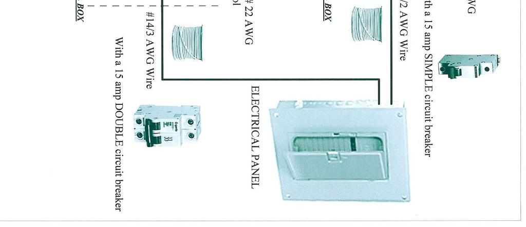
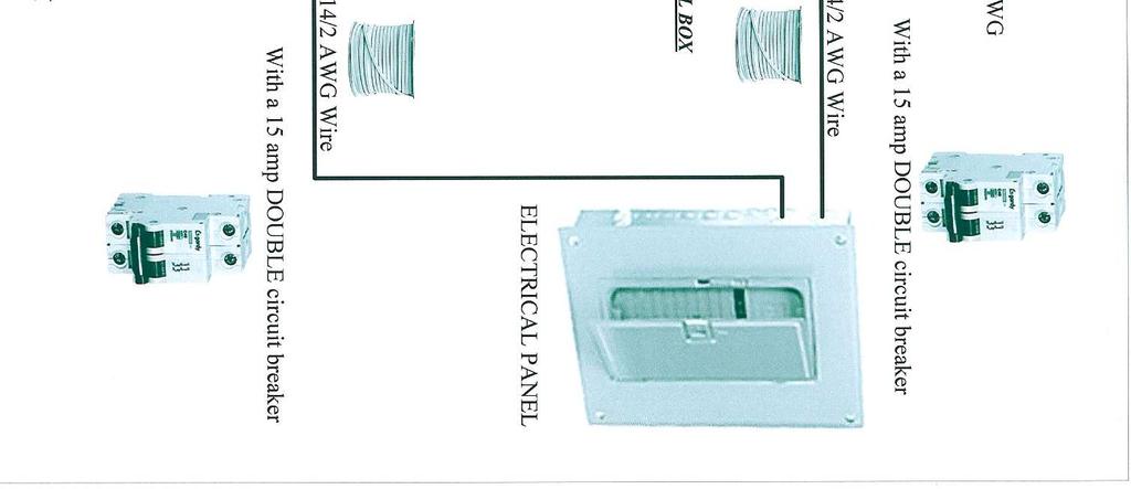
12 Wiring diagram This section discusses the various models of power relays available to control lights and how to connect. WARNING Always disconnect the main power before making connections control Observe standards of electrical code regulations in your area. To facilitate understanding of the connections and not to complicate the scheme, it indicates that the connection of a lamp. Do the same connections for other lamps. Because of the power consumed by ballasts, outlets for 120Vca lamps must be individually connected to a dedicated 15Amps circuit breaker. Wiring connections for 1 zone, for 120Vac ballast, see page 14 This diagram explains the connections of a 120Vca lighting system for 1 zone. The illustration of the connected lamp # 1 shows how to connect the system without using an online fan and the illustration of the line connected lamp # 2 shows how to connect the system with an online fan using Fan #1 output. If you have more than a fan, you can also use Fan #2 output. Wiring connections for 2 zones (without fan), see page 15 This diagram explains the connections of a lighting system to 120Vac for 2 zones without the use of online fan. Wiring connections for 2 zones (with fans), see page 16 This diagram explains the connections of a lighting system to 120Vac for 2 zones with the use of online fan. Connection made with relay PC2R 120/240 for 120Vac ballast, see page 17 This diagram explains the connections that can be done with 120Vac ballast. The upper drawing shows how to connect the power relay PC2R to control a lamp using a simple circuit breaker of 15 amps with #2/14 AWG wire. The lower drawing shows how to connect the power relay PC2R to control two lamps using a double breaker of 15 amps with # 3/14 AWG wire. Connection made with relay PC2R 120/240 for 240Vac ballast, see page 18 This diagram explains the connections that can be done with 240Vac ballast. It shows how to connect the power relay PC2R to control one or two lamps using a double breaker 15 amps with #2/14 AWG wire
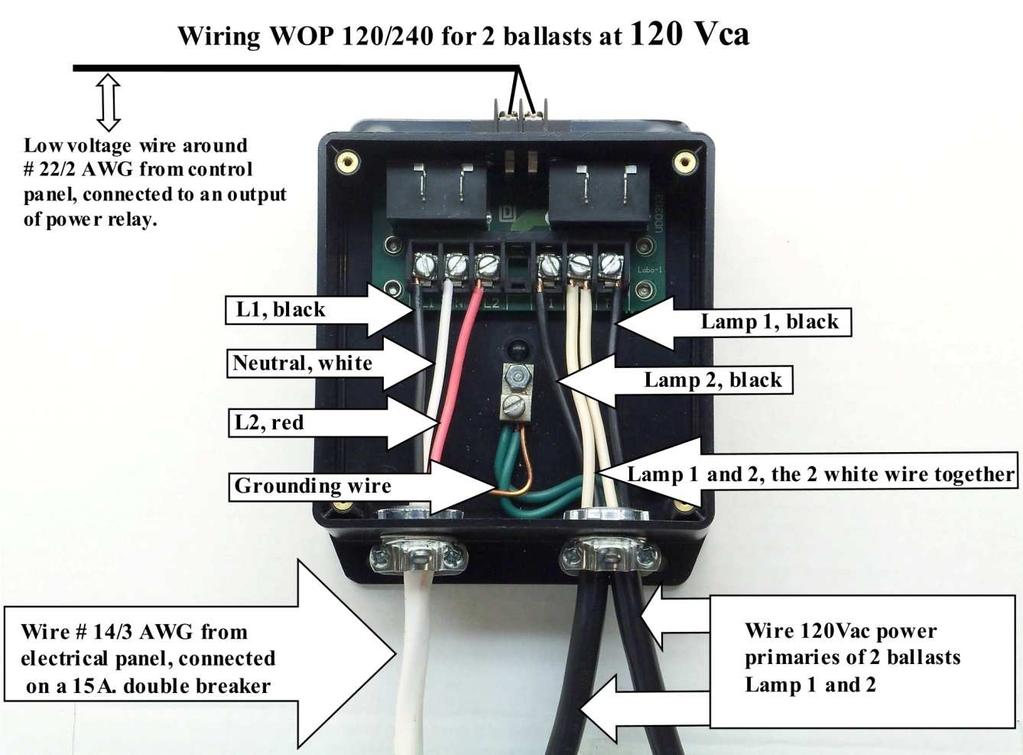
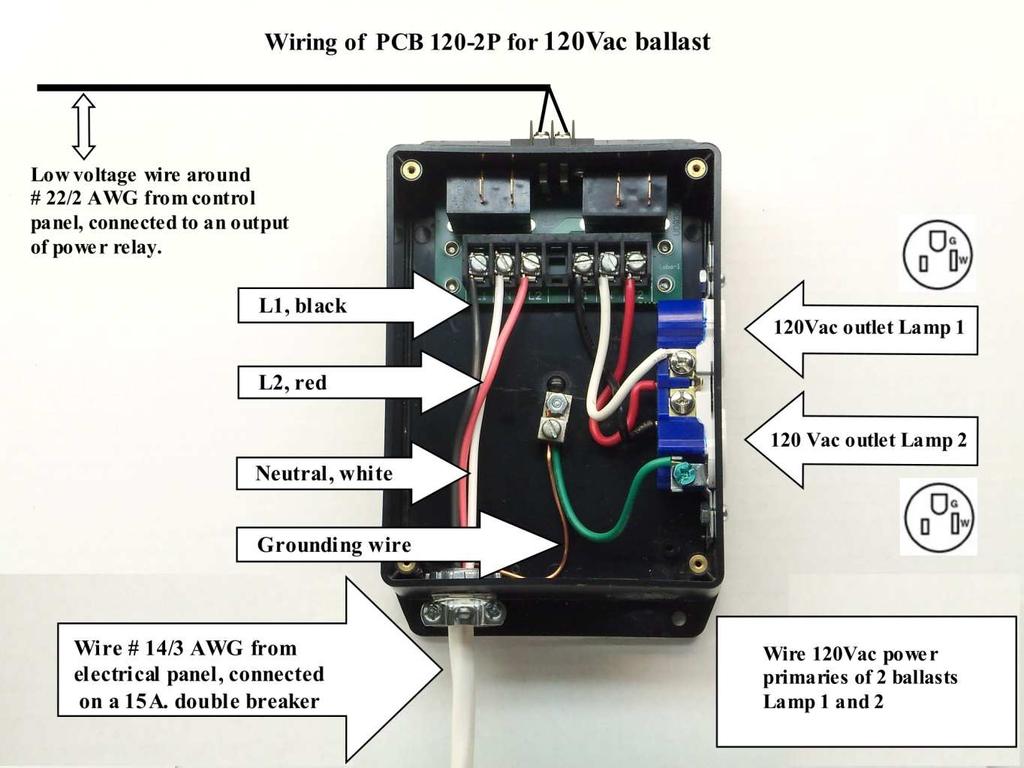
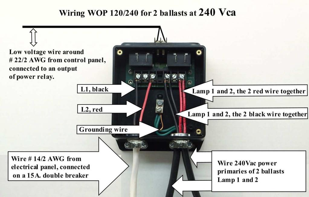
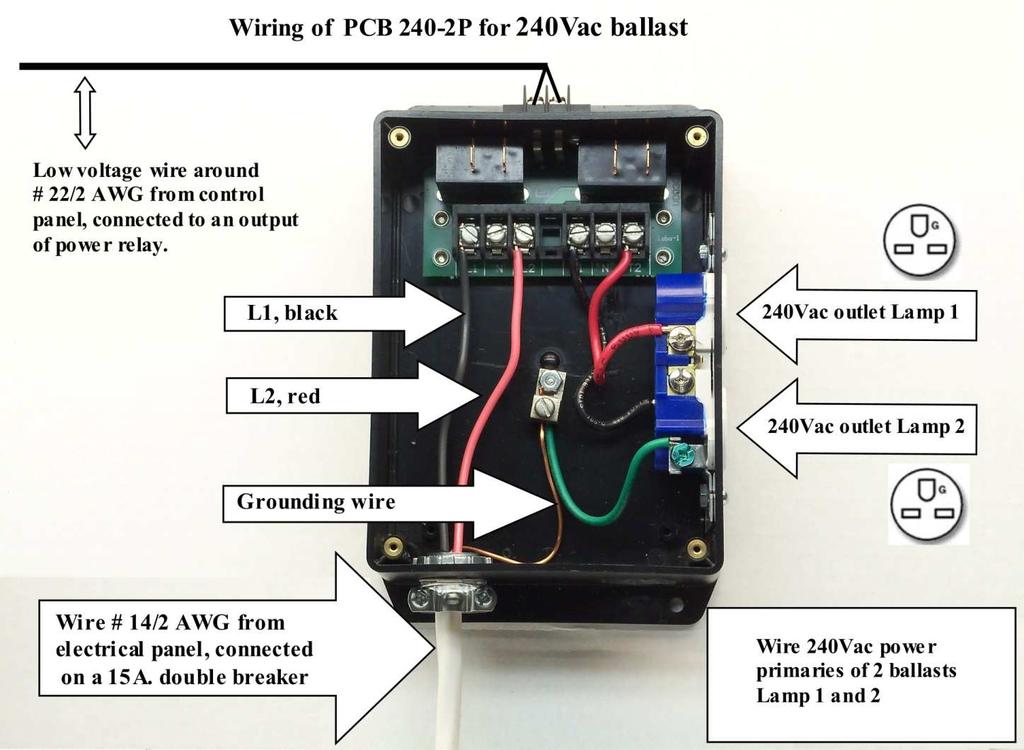
13 Connection made with relay WOP 120/240 for 120Vac ballast, see page 19 This diagram explains the connections that can be done with 120Vac ballast. It shows how to connect the power relay WOP 120/240 to control one or two lamps using a double breaker 15 amps with #3/14 AWG wire. Connection made with relay PCB 120-2P for 120Vac ballast, see page 19 This diagram explains the connections that can be done with 120Vac ballast. It shows how to connect the power relay PCB 120-2P to control one or two lamps using a double breaker 15 amps with #3/14 AWG wire. Connection made with relay WOP 120/240 for 240Vac ballast, see page 20 This diagram explains the connections that can be done with 240Vac ballast. It shows how to connect the power relay WOP 120/240 to control one or two lamps using a double breaker 15 amps with #2/14 AWG wire. Connection made with relay PCB 240-2P for 240Vac ballast, see page 20 This diagram explains the connections that can be done with 240Vac ballast. It shows how to connect the power relay PCB 240-2P to control one or two lamps using a double breaker 15 amps with #2/14 AWG wire. Coils parallel wiring of PRD-11AY0-120 relay (Option 2) This diagram describe below explains the connections of relay coils parallel transfer of ballast secondary for option 2. It also shows the location and number of screws for wiring diagram
14 - 14 -
15 - 15 -
16 - 16 -
17 - 17 -
18 - 18 -
19 - 19 -
20 - 20 -
21 Technical Sheet Main Control Dimensions L = 8,5 in W = 6,5 in H = 1,75 in L = 21,6 cm W = 16,5 cm H = 4,4 cm Input 16Vac, 60 Hz 3,0 Amps 50 Va Output 12Vdc 150 ma each Current 100 ma no load 1750 ma full load Slave Control Dimensions L = 8,5 in W = 6,5 in H = 1,75 in L = 21,6 cm W = 16,5 cm H = 4,4 cm Input 16Vac, 60 Hz 3,0 Amps 50 Va Output 12Vdc 150 ma each Current 50 ma no load 1700 ma full load Power relay PCR Vdc 75 ma PC2R 12Vdc 150 ma WOP 120/240 12Vdc 150 ma PCB 120-2P 12Vdc 150 ma PCB 240-2P 12Vdc 150 ma Udato Services Ltd Grande Allee Montreal, Qc, Canada H3L 2M4 Phone & Fax: servicesudato@bell.net
OPERATING INSTRUCTIONS
 COMFORT CONTROL CENTER 2 THERMOSTAT OPERATING INSTRUCTIONS PROGRAMMABLE THERMOSTAT MODEL 3314080.000 BLACK 3314080.015 WHITE USA SERVICE OFFICE Dometic Corporation 1120 North Main Street Elkhart, IN 46514
Installation, Operating and Maintenance Manual
 STATUS ZONES CONTROLS FIRE FAULT DISABLED FIRE 1 2 3 4 5 6 7 8 TEST FAULT DISABLED 1 5 BUZZER SILENCE RESET 1 2 TEST 2 6 LAMP TEST 3 SUPPLY 3 7 SYSTEM FAULT 4 8 SOUNDERS ACTIVATE/ SILENCE 4 FAULTS INSTRUCTIONS
User s Manual. TIGER S EYE E-Series Mark V Jockey. TIGERFLOW Systems, Inc Mint Way Dallas, Texas
 User s Manual TIGER S EYE E-Series Mark V Jockey TIGERFLOW Systems, Inc. 4034 Mint Way Dallas, Texas 75237 214-337-8780 www.tigerflow.com TABLE OF CONTENTS Introduction... 4 Sequence of Operation... 5
Instruction manual. WMCR-2, WMCR-3, WMCR-4 and WMCR-6 Circulator Zone Controllers WMCR-1E and WMCR-4E Expansion Modules
 Instruction manual WMCR-2, WMCR-3, WMCR-4 and WMCR-6 Circulator Zone Controllers WMCR-1E and WMCR-4E Expansion Modules This manual must only be used by a qualified heating installer/service technician.
DIESEL ENGINE CONTROL UNIT DCU USER S MANUAL - N-2000 Lillestrøm, Norway Tel: (+47) Fax: (+47)
 Fax: (+47)") DIESEL ENGINE CONTROL UNIT DCU 205 - USER S MANUAL - N-2000 Lillestrøm, Norway Tel: (+47) 64 84 52 00 Fax: (+47) 64 84 52 12 office@auto-maskin.no - 1 - TABLE OF CONTENTS 1. INTRODUCTION TO THE DCU 205...4
DIESEL ENGINE CONTROL UNIT DCU 205 - USER S MANUAL - N-2000 Lillestrøm, Norway Tel: (+47) 64 84 52 00 Fax: (+47) 64 84 52 12 office@auto-maskin.no - 1 - TABLE OF CONTENTS 1. INTRODUCTION TO THE DCU 205...4
ITC 2000 HEATING CONTROL CABINET. Installation & Operation Manual
 ITC 2000 HEATING CONTROL CABINET Installation & Operation Manual VTI, Incorporated 24 McMillan Way Newark, DE 19713 Phone (302) 738 0500 FAX (302) 738 6594 Revision Level 0.03 Manual No. 90003314 June,
IMPORTANT SAFEGUARDS READ AND FOLLOW ALL SAFETY INSTRUCTIONS. HZM-Series-Class I, Div 2 Battery Unit. Instalation instructions
 HZM-Series-Class I, Div 2 Battery Unit HZM-Series-Class I, Div 2 Battery Unit Instalation instructions IMPORTANT SAFEGUARDS 1 4 5 6 7 13 When using electrical equipment, basic safety precautions should
Technical Manual. Level Alarm Unit CARLA & WIDS
 CARLA & WIDS Technical Manual SAS au Capital de 2 158 244-444 871 933 R.C.S. Bourges - APE : 2651B Headquarter : 9, rue Isaac Newton - 18000 Bourges - France Technical Manual CARLA for Tankers Cargo Tanks
Model 17A00 Expansion Enclosure
 HOME AUTOMATION, INC. Model 17A00 Expansion Enclosure Installation Manual Document Number 17I00-1 Rev A March, 2002 Home Automation, Inc. Model 17A00 Expansion Enclosure Installation Manual Document Number
Digital Room Thermostat
 Digital Room Thermostat Instruction Manual Model No RT500 PRODUCT COMPLIANCE This product complies with the essential requirements of the following EC Directives: Electro-Magnetic Compatibility directive
SSV-DC user manual. Phason
 Phason SSV-DC user manual The SSV-DC has a 0 to 10 VDC signal output and a disconnect relay that allows you to easily and effectively control up to 10 variable frequency drives, slave units, modulating
HA-263K HA-263D. OWNER'S MANUAL Installation And Operation 8-ZONE ALARM CONTROL PANEL FOR HOME AND OFFICE PROTECTIONS OPEN THE CABINET FOR SERVICE
 D (OPERATION) INITIATE A DYNAMIC BATTERY TEST The system tests the back-up battery once every 24 hours. The owner can initiate a dynamic battery test at any time with the following codes while the system
User Manual. Dryer Controller M720
 User Manual Dryer Controller M720 Hardware version 1.00 Software version 1.00 Preliminary version Manual M720 Dryer controller Page 1 of 42 Document history Preliminary version: - Created in April, 2009
Specification/ Data Sheet
 Specification/ Data Sheet TRITON RP Agent Release Control Panel FEATURES Agent Release Control Panel designed specifically for suppression release operation with: Four initiating device circuits (IDCs)
IMPORTANT SAFEGUARDS READ AND FOLLOW ALL SAFETY INSTRUCTIONS. 3LERHZ Series Class I, Div 2 Combo Unit. Installation instructions
 3LERHZ Series Class I, Div 2 Combo Unit Installation instructions 3LERHZ Series Class I, Div 2 Combo Unit IMPORTANT SAFEGUARDS 1 3 When using electrical equipment, basic safety precautions should always
Premier Hazard STC Instructions
 PREMIER HAZARD Ltd Bessingby Industrial Estate Bridlington YO16 4SJ Tel: +44 (0) 113 239 1111 Fax: +44 (0) 113 239 1131 www.premierhazard.co.uk info@premierhazard.co.uk Premier Hazard STC Instructions
THA2 TEMPERATURE/ HUMIDITY/ DEWPOINT ALARM WITH LOGGING CAPABILITY. 99 Washington Street Melrose, MA Phone Toll Free
 99 Washington Street Melrose, MA 02176 Phone 781-665-1400 Toll Free 1-800-517-8431 Visit us at www.testequipmentdepot.com THA2 TEMPERATURE/ HUMIDITY/ DEWPOINT ALARM WITH LOGGING CAPABILITY Introduction.
03.03.mmm REV.2 09/01
 03.03.mmm REV.2 09/01 Via del Lavoro, 80-40056 CRESPELLANO (Bologna) ITALY - ( +39 051/733.383 - Fax. +39 051/733.620 P.O. BOX, 150-40011 ANZOLA EMILIA (Bologna) - ITALY Power Factor Regulator cosφ V A
Section 1 General Description
 CX-33 Advanced Logic Relay Installation Instructions Firmware Ver. 2.5 Section 1 General Description The CX-33 is the latest generation multi-purpose logic control. It is designed to be versatile yet user
Lubrication cycle IP Enclosure Rating. 110 VAC, 220/230 VAC (50/60 Hz) Alarm Fault Relay Contacts. IP-55 (Liquid tight connector)
 Alarm Fault Relay Contacts. IP-55 (Liquid tight connector)") SMAC Controller Industrial Lubrication Systems Operation The SMAC Controller is a multi-purpose programmable controller used with industrial lubrication systems. Controller settings are saved whenever
SMAC Controller Industrial Lubrication Systems Operation The SMAC Controller is a multi-purpose programmable controller used with industrial lubrication systems. Controller settings are saved whenever
OWNER S MANUAL. High-Wall Fan Coil Unit CONTENTS
 OWNER S MANUAL High-Wall Fan Coil Unit Page GENERAL 2,3 OPERATING MODES 2 REMOTE CONTROL 2 OPERATION 3-9 REMOTE CONTROL OPERATION 3 INDOOR UNIT DISPLAY 5 EMERGENCY OPERATION 5 PRESSING THE ON/OFF BUTTON
RANGER 8600 DOWNLOADABLE CONTROL COMMUNICATOR INSTALLATION MANUAL
 RANGER 8600 DOWNLOADABLE CONTROL COMMUNICATOR INSTALLATION MANUAL TABLE OF CONTENTS GENERAL DESCRIPTION... 2 STANDARD AND OPTIONAL PARTS LIST... 2 PARTS DIAGRAM... 3 TERMINAL DRAWING AND SPECIAL NOTES...
Introduction. OM-THA2
 Introduction. The OM-THA2 is a multi-function product that monitors Temperature, Humidity and Dew Point, provides alarms for out of range conditions, and continuously logs data. It consists of a base unit
TECHNICAL DATA. Humidity: 85% Relative Humidity (non-condensing) at 90 F (32 C) maximum.
 at 90 F (32 C) maximum.") September 29, 1997 Firecycle III 433 a 1. PRODUCT NAME VIKING Model E-1 Manufactured 1997 Present 2. MANUFACTURED FOR THE VIKING CORPORATION 210 N Industrial Park Road Hastings, Michigan 49058, U.S.A.
September 29, 1997 Firecycle III 433 a 1. PRODUCT NAME VIKING Model E-1 Manufactured 1997 Present 2. MANUFACTURED FOR THE VIKING CORPORATION 210 N Industrial Park Road Hastings, Michigan 49058, U.S.A.
IT801 Thermostat. User s Manual. The complete guide to the set up and operation of your new smart Wi-Fi thermostat.
 IT801 Thermostat User s Manual The complete guide to the set up and operation of your new smart Wi-Fi thermostat. The smart Wi-Fi thermostat system learns your comfort preferences, then finds opportunities
SMART EVO 2 - User Manual ELECTRICAL PANEL FOR 2 MOTORS
 SMART EVO 2 - User Manual ELECTRICAL PANEL FOR 2 MOTORS CONTENTS 1. INTRODUCTION... 5 2. WARNINGS... 6 3. GENERAL DESCRIPTION... 7 4. INSTALLATION... 8 5. LUMINOUS INDICATORS AND COMMANDS... 9 6. DIP-SWITCH
MR-2602 Two Zone Fire Alarm Control Panel
 MR-2602 Two Zone Fire Alarm Control Panel Installation Manual Secutron LT-2015 Rev.3 July 2010 Table of Contents 1 Introduction 1.1 The MR-2602 Fire Alarm Control Unit... 11 1.1.1 General features...
Peak Partners Web-Programmable Thermostat Homeowner s Manual. Look inside for a complete guide to the setup and operation of your new thermostat.
 Peak Partners Web-Programmable Thermostat Homeowner s Manual Look inside for a complete guide to the setup and operation of your new thermostat. Table of Contents Step 1: Getting Started...4-6 A. Thermostat
Static Pressure Control
 The (model SPC-2) is a fully programmable controller that provides extensive flexibility for your curtain or awning control needs. The SPC-2 automatically controls the pressure in a room by operating a
Dryer Controller M720
 User Manual Dryer Controller M720 Hardware version 2.00 Software version 2.00 Manual M720 Dryer controller Page 1 of 60 Document history Preliminary version: - Created in April, 2009 Hardware Version 2.00,
Instructions. Easy-wire terminal strip Microprocessor-operated. Easy remote sense. Self-checking program. Diagnostic/status LED s
 Instructions Rear (size reduced) Easy-wire terminal strip Microprocessor-operated Front (Processor coordinates operation and diagnostic) Easy remote sense (Electronic sensor, wired to control) Self-checking
Small in size, with grand features USER GUIDE Elle-même petite, mais avec caractéristique grand
 1 Small in size, with grand features USER GUIDE Elle-même petite, mais avec caractéristique grand 2 PARAMETER LIST 00 Elevator Type 01 Command Type 02 Door Type 03 Automatic Door at Floor 04 Automatic
TFD-1 Installation & User s Guide
 TFD-1 Installation & User s Guide TABLE OF CONTENTS CHAPTER 1 - INTRODUCTION... 4 1.1 GENERAL...4 1.2 DESCRIPTION...4 CHAPTER 2 - INSTALLATION... 5 2.1 UNPACKING...5 2.2 MOUNTING...5 2.3 SWITCH SETTINGS...6
MANUAL. OEM (Unit) OZONE GENERATOR (100VA, 200VA and 300VA) INDEX
 OZONE GENERATOR (100VA, 200VA and 300VA) INDEX") MANUAL OEM (Unit) OZONE GENERATOR (100VA, 200VA and 300VA) INDEX 1) Technical Specifications: (100VA, 200VA, 300VA) 2) Introduction 3) Construction 4) Operation and maintenance a) Operating Procedure b)
MANUAL OEM (Unit) OZONE GENERATOR (100VA, 200VA and 300VA) INDEX 1) Technical Specifications: (100VA, 200VA, 300VA) 2) Introduction 3) Construction 4) Operation and maintenance a) Operating Procedure b)
Automatic Phone-Out Home Monitoring Systems
 Automatic Phone-Out Home Monitoring Systems Power Outage, Freeze and Flood Alarm Product Description Model Number: THP201 These monitoring systems are intended to monitor homes, cabins, and other premises
PNC 1000 SERIES 2, 4, 8 Zone Fire Alarm Control Panel
 PNC 1000 SERIES 2, 4, 8 Zone Fire Alarm Control Panel INSTALLATION, OPERATION AND MAINTENANCE MANUAL Version: CN-PM-1000.VER1.1-12/2012 EN54 INFORMATION In accordance with EN 54-2 clause 13.7, the maximum
Saffire User & Installation Manual. IMPORTANT This manual should be left with the panel after installation.
 Saffire+ 8-12 User & Installation Manual IMPORTANT This manual should be left with the panel after installation. We reserve the right to change product specifications without prior notice. Copyright VRC
FireNET Plus Wiring Instructions
 FireNET Plus Wiring Instructions This manual provides wiring instructions for the 1 loop and 2 loop version of the FireNET Plus panels, which supports our finest Hochiki s DCP protocol. Note: Refer to
ESRTPRF. Wireless Programmable Room Thermostat, with Delayed & Optimum Start. User and Installation Instructions M/A MANUAL
 M/A MANUAL ESRTPRF Wireless Programmable Room Thermostat, with Delayed & Optimum Start User and Installation Instructions INDEX User Instructions What is a Programmable Room Thermostat? 1 Introduction
PDD-8PCI. Power Distribution Board With Supervised Interface. Installation and Specifications Manual
 INSTALLATION PDD-8PCI PDD-8PCI Power Distribution Board With Supervised Interface Installation and Specifications Manual Details The PDD-8PCI board is a power distribution/control interface. This board
CSP-204 CSP-208 CSP-104 CSP-108
 Fire Alarm Control Panel CSP-204 CSP-208 CSP-104 CSP-108 Operation manual Firmware version 1.1 csp-x_o_en 06/15 SATEL sp. z o.o. ul. Budowlanych 66 80-298 Gdańsk POLAND tel. 58 320 94 00 www.satel.eu CONTENTS
MR4PMUHV Electronic. Temperature/Defrost Control with Relay Pack
 Master Catalog 125 Temperature Controls Section A Product/Technical Bulletin Issue Date 1098 MR4PMUHV Electronic Temperature/Defrost Control with Relay Pack The MR series temperature controls are designed
Service manual. Type: TD25. Contents
 Service manual Type: TD25 Contents Introduction...3 Type overview...4 Programme...5 Indication of programme sequence...5 Options and settings...6 Variant settings...8 Test programme...9 Troubleshooting...11
F PC and AO OUTPUT BOARDS INSTRUCTION MANUAL. Blue-White. Industries, Ltd.
 F-2000 PC and AO OUTPUT BOARDS INSTRUCTION MANUAL Blue-White R Industries, Ltd. 500 Business Drive Huntington Beach, CA 92649 USA Phone: 714-89-8529 FAX: 714-894-9492 E mail: sales@blue-white.com or techsupport@blue-white.com
XWA11V-KIT Walk-In Temp / Door /Alarm / Light Module with Mounting Box and Wiring
 XWA11V-KIT Walk-In Temp / Door /Alarm / Light Module with Mounting Box and Wiring 1. GENERAL DESCRIPTION Model XWA11V-KIT, 100x64 mm format, is a microprocessor based light and alarm management controller,
Alarm Tone Generator Model AG17
 Alarm Tone Generator Installation & Operation P005089 Rev. C 150930 9/30/2015 12:25 PM Ph: 403.258.3100 \ email:info@guardiantelecom.com \ www.guardiantelecom.com Table of Contents Package Contents...
TECHNICAL DATA OBSOLETE
 Deluge Devices 270a 1. PRODUCT NAME VIKING PAR-3 Available since 1991 2. MANUFACTURED FOR: THE VIKING CORPORATION 210 N. Industrial Park Road Hastings, Michigan 49058 U.S.A. Telephone: (269) 945-9501 (877)
Thermostats. Digital Programmable. GEAppliances.com
 GEAppliances.com Digital Programmable Thermostats Owner s Manual & Installation Instructions RAK148P2 RAK164P2 Configuration Mode...8 9 Important Safety Information... 2 Installation Instructions... 4
INSTALLATION AND USER MANUAL
 INSTALLATION AND USER MANUAL t Thank you for choosing Aqua inverter heat pump. This manual provides you necessary information for optimal use and maintenance, please read it carefully and keep it for subsequent
RANGER 7600 DOWNLOADABLE CONTROL COMMUNICATOR INSTALLATION MANUAL
 RANGER 7600 DOWNLOADABLE CONTROL COMMUNICATOR INSTALLATION MANUAL TABLE OF CONTENTS 1. TABLE OF CONTENTS... P.1 2. GENERAL DESCRIPTION... P.2... 3. STANDARD AND OPTIONAL PARTS LIST... P.2... 4. FEATURE
CONTROL PANEL INTERFACE ACTIVATE THE GENERATOR DISPLAY INTERFACE MENUS. Control Panel USING THE AUTO/OFF/MANUAL SWITCH
 CONTROL PANEL INTERFACE USING THE AUTO/OFF/MANUAL SWITCH With the switch set to AUTO, the engine may crank and start at any time without warning. Such automatic starting occurs when utility power source
ADDITIONAL INFORMATION
 MODEL APS-3C AUTOMATIC SNOW/ICE MELTING SYSTEM CONTROL PANEL MODEL APS-4C AUTOMATIC SNOW/ICE MELTING SYSTEM CONTROL PANEL MODEL SC-40C MODULAR SNOW/ICE HEATER CONTROL SYSTEM SAFETY This device provides
USER MANUAL COMBINED FIRE & EXTINGUISHING CONTROL PANEL COMPLIES WITH BS EN PART 1 & EN54 PARTS 2 & 4
 PREMIER EX8 EXTINGUISHING PANEL USER MANUAL COMBINED FIRE & EXTINGUISHING CONTROL PANEL COMPLIES WITH BS EN 12094 PART 1 & EN54 PARTS 2 & 4 USER MANUAL Approved Document No: GLT.MAN-132 INDEX Extinguishing
Installation Manual CFP-105. Fire Alarm Control Panel. Version 1.0
 CFP-105 Fire Alarm Control Panel Installation Manual Version 1.0 WARNING: This manual contains information on limitations regarding product use and function and information on the limitations as to liability
SECTION LOW VOLTAGE LIGHTING CONTROLS
 SECTION 26 09 26 LOW VOLTAGE LIGHTING CONTROLS PART 1 - GENERAL 1.01 RELATED DOCUMENTS: A. The Conditions of the Contract and applicable requirements of Division 1, "General Requirements", and Section
HOKKIM INTEGRATED AMF CONTROL BOARD MANUAL FOR MODELS: HAMF-8 AND HAMF-4
 HOKKIM INTEGRATED AMF CONTROL BOARD MANUAL FOR MODELS: HAMF-8 AND HAMF-4 INTRODUCTION Thank you for purchasing the Hokkim Integrated Automatic Mains Failure Control Board model HAMF- 8 or HAMF-4. We shall
The CAB & DAB Air Curtains
 The CAB & DAB Air Curtains Frequently Asked Questions General Positioning Page 2 Electrical & Connection Page 4 Electric Heated Page 5 Electronic door triggered shutdown feature (Electric) Page 5 Electronic
INSTALLATION INSTRUCTIONS TEC40 ELECTRONIC CONTROLLER
 INSTALLATION INSTRUCTIONS TEC40 ELECTRONIC CONTROLLER BARD MANUFACTURING COMPANY Bryan, Ohio 43506 Since 1914...Moving ahead, just as planned. Manual: 2100-393C Supersedes: 2100-393B File: Volume III Tab
Technical Manual Binair Monobloc Heat Pump
 Technical Manual Binair Monobloc Heat Pump MODEL BINAIR12 Introduction Disassembly of the machine must be carried out by any professional or any special agency assigned by us. All operation and maintenance
ARM SERIES Switching Relays With Priority
 Models ARM-2P ARM-3P ARM-4P ARM-6P AD-1 AD-4 ARM SERIES Switching Relays With Priority INSTALLATION, OPERATION & MAINTENANCE MANUAL ARM-2P ARM-4P AD-1 ARM-3P ARM-6P AD-4 Information and specifications
UltraLITE Model ELU Centralized Emergency Lighting Inverter 4.2 KW- 5 KW
 12/23/16 Rev 9 UltraLITE Model ELU General Specification 4.2 KW to 5 KW UltraLITE Model ELU Centralized Emergency Lighting Inverter 4.2 KW- 5 KW 1.0 General General Specification This specification describes
Heat Link. Technical Guide
 Heat Link Stat Link Technical Guide Third Version, May 2011 1 Table of Contents Thermostatic Zones Defined...................................... 4 StatLink System Components.....................................
STARS SHOULD BE WELL LIT.
 STARS SHOULD BE WELL LIT. PROGRAMMABLE LIGHTING CONTROL SMART CONTROLS WILL HELP THEM STEAL THE SHOW. A PRECISE AND EASY MANAGEMENT OF YOUR POULTRY HOUSE LIGHTHING MAKES YOUR FARM GROW SMARTER. PRECISE
Installation Instructions
 Specifications PW-100 PW-200 PW-100/PW-100-347/PW-200/PW-200-347 v3 Passive Infrared Wall Switch Occupancy Sensor PW-100-347 PW-200-347 Voltages: PW-100 & PW-200................ 120/277VAC, 50/60Hz PW-100-347
PSC-ID-x-CM Series Ceiling Mount Occupancy Sensor
 TECHNICAL SPECIFICATIONS PSC-ID-x-CM Series Ceiling Mount Occupancy Sensor Basic Features Line voltage version: 120-277VAC, 60Hz Low voltage version: 24VDC, requires separate class 2 power supply PIR sensor
WARNING Important Safety Information
 1 Specifications Premier Series Non-Programmable Thermostats MODEL 3000 MODEL 3200 1 2 3 4 5 Specifications Installation Testing Your New Thermostat Programming User Settings Temperature Adjustment WARNING
SACE PR021/K SIGNALLING UNIT
 SACE PR021/K SIGNALLING UNIT 1SDH000559R0002 L3016 1/52 EN CONTENTS 1. GENERAL INFORMATION...4 1.1. FOREWORD...4 1.2. APPLICABLE SCENARIOS...5 2. TECHNICAL SPECIFICATIONS...6 2.1. ELECTRICAL CHARACTERISTICS...6
INSTALLATION AND USER MANUAL
 INSTALLATION AND USER MANUAL Thank you for choosing inverter heat pump. This manual provides you necessary information for optimal use and maintenance, please read it carefully and keep it for subsequent
GV60 REMOTE CONTROL user guide
 GV60 REMOTE CONTROL user guide 919-713 09.20.16 General Notes... 4 Coding instructions:... 5 To Turn ON Appliance:... 5 To Turn OFF Appliance:... 5 Flame height adjustment... 6 To open and close solenoid
MHWW-24-H-1 Chilled/Hot Water Hi-Wall Fan Coil 2-Pipe Heat / Cool Fan Coil 24,000 BTUH
 MHWW-24-H-1 Chilled/Hot Water Hi-Wall Fan Coil 2-Pipe Heat / Cool Fan Coil 24,000 BTUH MHWW NOMENCLATURE BREAKDOWN 2-Pipe Heat/Cool Hi-Wall Fan Coil MHWW- 24 - H -1 2-Pipe Heat/Cool Heat/Cool Voltage 1=
MHWW-09-H-1 Chilled/Hot Water Hi-Wall Fan Coil 2-Pipe Heat / Cool Fan Coil 9,000 BTUH
 MHWW-09-H-1 Chilled/Hot Water Hi-Wall Fan Coil 2-Pipe Heat / Cool Fan Coil 9,000 BTUH MHWW NOMENCLATURE BREAKDOWN 2-Pipe Heat/Cool Hi-Wall Fan Coil MHWW- 09 - H -1 2-Pipe Heat/Cool Heat/Cool Voltage 1=
ABOUT THIS DOCUMENT AND THE DOCUMENT STRUCTURE WE USE
 ABOUT THIS DOCUMENT AND THE DOCUMENT STRUCTURE WE USE isocket Smart Relay is a complex Smart House system which is installed in the fuse cabinet (electric cabinet) in the house. We therefore assume that
Secondary Sensing System
 Secondary Sensing System Owners Manual Hired Hand Mfg., Inc. 1733 Co Rd 68 PO Box 99 Bremen, Alabama 35033 Manual No. 4801-2997 Rev 7-04 Owners Manual Secondary Sensing System Table of Contents Section
BENTEL SECURITY reserves the right to modify the technical features of this product without prior notice.
 BENTEL SECURITY reserves the right to modify the technical features of this product without prior notice. via Florida Z.I. Valtesino - 63013 GROTTAMMARE (AP) - ITALY Installation and Quick guide: DUAL
La Marche Manufacturing Company Option 16 Series. Digital Combined Accessory Package. Installation and Operation Manual
 La Marche Manufacturing Company www.lamarchemfg.com Option 16 Series Digital Combined Accessory Package Installation and Operation Manual This manual is subject to change without notice. You may obtain
MASTER PRESSRE MAINTANENCE CONTROLLER. Models PMCE INSTRUCTION MANUAL. C 2018 Master Control Systems, Inc
 MASTER PRESSRE MAINTANENCE CONTROLLER Models PMCE INSTRUCTION MANUAL C 2018 Master Control Systems, Inc TABLE OF CONTENTS Important Safety Information. Page 3 General Description and Installation.. Page
BTU Units WORKING PROGRAM MANUAL
 9000-24000BTU Units WORKING PROGRAM MANUAL SUMMARIZE FUNCTIONS & OPERATION MODES TIMER, SLEEP MODE, FAN SPEED PROTECTION FUNCTIONS EMERGENCY SWITCH TEST GUIDE MEMORY FUNCTIONS SUMMARIZE The Operation Modes
Heat Pump Defrost Board Replacement Kit
 Bard Manufacturing Company, Inc. Bryan, Ohio 43506 8620-223 Heat Pump Defrost Board Replacement Kit KIT FEATURES This kit is made up of the current defrost control board 8201-129 and a new defrost sensor.
MASTER JOCKEY PUMP CONTROLLER. Model JPCE INSTRUCTION MANUAL. C 2018 Master Control Systems, Inc
 MASTER JOCKEY PUMP CONTROLLER Model JPCE INSTRUCTION MANUAL C 2018 Master Control Systems, Inc TABLE OF CONTENTS Important Safety Information. Page 3 General Description and Installation.. Page 4 Model
Thank you for buying a DEVI product. With this purchase you have obtained a product of the highest quality, designed to give long lasting comfort at
 Devireg 550 INT Thank you for buying a DEVI product. With this purchase you have obtained a product of the highest quality, designed to give long lasting comfort at a minimum of environmental impact. 2
Control/Communicator Installation Manual
 DAS NETWORX NX-12 Control/Communicator Installation Manual General Description...2 Ordering Information...2 Option Definitions...3 Programming the LED Code Pads...5 Programming the NX-12...9 Types of Programming
BX444-Mc Gas Detector
 Installation and User Guide Rev.01. BX444-Mc Gas Detector Application Duomo is recognised within the gas industry for providing a comprehensive range of low cost, high reliability gas detection for many
1200-HCM DIN RAIL MOUNTING FIRE SYSTEM MODULE Fire Detection & Extinguishant Control A R T PATOL LIMITED SUPPLY FAULT SOUNDER
 Application The unit is primarily intended for use where there is a requirement to integrate a limited fire protection function into a larger control equipment scheme, or in specialist applications where
WARNING Important Safety Information
 1 Specifications Premier Series Non-Programmable Thermostats MODEL 3000 MODEL 3200 1 2 3 4 Specifications Installation Testing Your New Thermostat Programming User Settings WARNING Important Safety Information
Intelligent Security & Fire Ltd
 full installation, commissioning and operating manuals can be downloaded from www.haes-systems.co.uk combined addressable / conventional fire alarm control panel User Guide Approved Document No. MFBU-04
SPECIFICATIONS for AIR CONDITIONING CONTROLLER ZONE CONTROL
 SPECIFICATIONS for AIR CONDITIONING CONTROLLER ZONE CONTROL 1. INTROUCTION Zone control is a two pieces fan coil thermostat available for Heat/Cool versions. Its application is for the duct type system
Cimco Series 21. Series 21 - Operator Instruction Manual INDEX. Description. Standard Instructions 2 to 4. Operating Control Panel 5
 Series 21 - Operator Instruction Manual INDEX Description Page Standard Instructions 2 to 4 Operating Control Panel 5 Monitoring Features 6 to 7 Page 1 of 7 Series 21 with Microprocessor STANDARD INSTRUCTIONS
ECO-IR 360C NT. Presence detector. Art. Nr Bedienungsanleitung 2. Notice d utilisation 22. Installation manual 42
 Presence detector ECO-IR 360C NT Art. Nr. 202 0 400 D F GB E I NL S N FIN DK Bedienungsanleitung 2 Notice d utilisation 22 Installation manual 42 Manual de instrucciones 62 Istruzioni per l uso 82 Gebruikershandleiding
Digiplex LED Keypads User s Manual
 KLEDEU03.fm Page -1 Friday, May 4, 2001 11:25 AM Digiplex LED Keypads User s Manual KLEDEU03.fm Page 0 Friday, May 4, 2001 11:25 AM KLEDEU03.fm Page 1 Friday, May 4, 2001 11:25 AM TABLE OF CONTENTS 1.0
Table 1. Serie of Digital Room Thermostats.
 Digital Room Thermostats INSTALLATION MANUAL APPLICATION DR is a serie of Digital Room Thermostats, provides a single stage, temperature control. Table 1 shows all the available models. All models can
MR3CCUHV Temperature/Defrost Control
 Master Catalog 125 Temperature Controls Section A Product/Technical Bulletin Issue Date 0401 MR3CCUHV Temperature/Defrost Control The MR3CCUHV Temperature/Defrost Control is designed to control the temperature
Securitron Magnalock Corporation S. 51 st St., Ste. 102 Phoenix, AZ Phone: (800) MAGLOCK
 MAGLOCK") Installation Manual AQM-20 12vdc/24vdc Series Power Supplies AQM20 Supervised Power Supply/Charger 12vdc 20Amp/24vdc 10Amp Life Time Warranty Quality Manufactured in the USA AQM20 Features: The AQM20 has
Installation Manual AQM-20 12vdc/24vdc Series Power Supplies AQM20 Supervised Power Supply/Charger 12vdc 20Amp/24vdc 10Amp Life Time Warranty Quality Manufactured in the USA AQM20 Features: The AQM20 has
Conventional Releasing Control Panel
 s Data Sheet Fire Safety Products Conventional Releasing Control Panel Pre-Action Deluge Agent-Releasing Fire System Model TXR-320 Remote configurable Up to two (2) hazard areas Operable with the following:
Dual Technology Wall Mounted Occupancy Sensor. Manual & Specification
 Dual Technology Wall Mounted Occupancy Sensor Manual & Specification PRODUCT MUST BE INSTALLED IN ACCORDANCE WITH LOCAL ELECTRICAL CODES Douglas Lighting Controls Page 1 December 16, 2013 1. INTRODUCTION
Dual Technology Wall Switch Occupancy Sensor. Manual & Specification
 Dual Technology Wall Switch Occupancy Sensor Manual & Specification PRODUCT MUST BE INSTALLED IN ACCORDANCE WITH LOCAL ELECTRICAL CODES Douglas Lighting Controls Page 1 November 19, 2014 1. INTRODUCTION
Installation and Operation Manual
 SENTRY Protect Plus QUADPLEX PANEL Installation and Operation Manual For Hardwired Pumps Environment e Corporation Table of Contents 1 Overview...3 2 Sentry Protect Plus Quadplex Menu Flowchart...4 3 Wiring
: PRT / PRT PRT / PRT-N1
 Model: PRT / PRT-N Model: PRT / PRT-N 1 Model: PRT / PRT-N Table of Contents Product Image Table of Contents What is a Programmable Room Thermostat? Installation Procedure LCD Display Setting the Clock
Fax (724) Main St.; P. O. Box 248 West Middlesex, PA IMPORTANT NOTICE
 Main St.; P. O. Box 248 West Middlesex, PA IMPORTANT NOTICE") Phone (724) 528-9559 Cimco Electronics, Inc. Fax (724) 528-1108 26 Main St.; P. O. Box 248 West Middlesex, PA 16159 Oct., 2002 IMPORTANT NOTICE Dear Customer, We would like to make you aware of a few hardware
Phone (724) 528-9559 Cimco Electronics, Inc. Fax (724) 528-1108 26 Main St.; P. O. Box 248 West Middlesex, PA 16159 Oct., 2002 IMPORTANT NOTICE Dear Customer, We would like to make you aware of a few hardware
PTE0705 Electric Fence Monitor
 PTE0705 Electric Fence Monitor The JVA logo is a registered trademark of JVA Technologies. JVA Technologies. TABLE OF CONTENTS DESCRIPTION... 2 QUICK START GUIDE... 3 FEATURES... 4 EXPLANATION OF TERMS...
Programmable Electronic Thermostat
 INSTRUCTION MANUAL Programmable Electronic Thermostat We thank you for trusting Aube technologies and hope that you will be entirely satisfied. For any questions concerning the TH141A-HC-28 progammable