BENTEL SECURITY reserves the right to modify the technical features of this product without prior notice.
|
|
|
- Zoe Horton
- 5 years ago
- Views:
Transcription


1
2 BENTEL SECURITY reserves the right to modify the technical features of this product without prior notice. via Florida Z.I. Valtesino GROTTAMMARE (AP) - ITALY Installation and Quick guide: DUAL CHANNEL TELEPHONE DIALLER B-TEL99 ISTRUZIONI AVVISATORE TELEFONICO B-TEL99 ISTB-TEL99
3 TABLE OF CONTENTS INTRODUCTION 5 General features Description Alarm cycle Technical features Parts INSTALLATION 11 Mounting Description of the terminals Basic connections Auxiliary connections PROGRAMMING 15 Fast Keys New values Programming chart Installer PIN: Access to the programming phase Telephone numbers Alarm messages Long Common Message - Short Channel 1 Message - Brief Dedicated Channel 1 Message Alarm Channel 2 Short Message - Brief Dedicated Channel 2 Message Short Common Message User Command PIN TABLE OF CONTENTS 3
4 Options Option 1) Message Management Option 2) Number of call cycles Option 3) Message playback time Option 4) Dialling type Option 5) Dial-tone check Option 6) Voice answer detection Option 7) Dial-tone type Activation mode Logger QUICK GUIDE 31 Stop Alarm Stop Alarm cycles via telephone Listen-in Telephone dialler B-TEL99
5 INTRODUCTION General features Dialler 2 independent alarm channels with priority management. Message choices: Long Common Message of 32 seconds (common to both channels); Two Dedicated Messages of 16 seconds (one message per channel); Short Common Message of 16 seconds (common to both channels) 2 Brief Dedicated Messages of 8 seconds (one per channel). 255 event logger, each event shows: called telephone number, the trigger channel and call result. Stop alarm cycle/s and Listen-in via remote telephone, by means of modifiable User Command PIN. Stop Alarm by means of modifiable User Command PIN on B-TEL99 keypad. 7 programmable telephone numbers for each channel. Up to 15 digits per telephone number; pauses of 1 or 5 seconds may be entered. Repeats the alarm message for 20, 40, 60 or 80 seconds. Repeats call cycle/s up to 5 times. Stop alarm cycle/s terminal. Access to programming by means of modifiable Installer Command PIN on keypad. Programmable alarm-call activation by positive drop or negative command. "Voice answer detection" option. Protection against accidental battery polarity inversion. Telephone line Test for telephone-line fault and cutting, with anomaly signalling on opencollector output. Bypassable "dial tone" check. Electronic telephone-line interface. Over-voltage protection. Programmable as DTMF (tone) or pulse dialling. INTRODUCTION 5
6 Interface Digital recording/playback of messages. Built-in loudspeaker for message playback. Single digit LED display. Alphanumeric command keypad. Non-volatile memory for programmed data storage. Container Tamper protection. Compartment for 12 V Ah battery (not supplied). Description The B-TEL99 telephone dialler calls and sends messages to a series of programmed telephone numbers. The plastic box (ABS) of the B-TEL99 should be mounted near to the control panel. The B-TEL99 can monitor two different event types (e.g. burglary alarm and fire alarm). It is possible to assign relevant voice messages to each event type. The messages are recorded on a non-volatile memory which avoids the usual problems connected with magnetic tape such as: message quality loss and mechanical hitches after long periods of device inactivity. The B-TEL99 has a built-in loudspeaker for recorded message playback (for message quality checks). The alphanumeric keypad and LED display make parameter programming quick and easy. The box is protected against tamper and has a compartment for a 12 V Ah battery (not supplied). Alarm cycle In the event of an alarm status on an alarm channel, the telephone dialler will carry out the alarm cycle, illustrated in figure 1, for each of the telephone numbers programmed for the channel in question. Phase 1 Phase 2 Phase 3 The telephone dialler switches the telephone line from any connected telephone device or devices (connected to terminals LI) to the B-TEL99 interface. After 3 seconds the telephone will hook the connected telephone line. If the Dial-tone check is enabled (see "Dial-tone check" programming option 7) the B-TEL99 will check for the dial tone, if the dial tone is detected the B-TEL99 will step to successive phase. If the dial tone is not detected (option enabled) the B-TEL99 will release the telephone line and step back to phase1. 6 Telephone dialler B-TEL99
7 The Dial-tone check will be carried out 4 times, after which the B-TEL99 will step to the successive telephone number, and restart from phase 1. If this option is disabled the B-TEL99 will step directly to the successive phase. Phase 4 Phase 5 Phase 6 Call cycle The B-TEL99 will dial the telephone number (1 to 7) assigned to the alarm channel in alarm status, and will show (one by one) the dialled digits on the display. If the Voice answer detection option is enabled, the B-TEL99 will wait 25 seconds for a voice answer and, when voice answer is detected, the B-TEL99 will step to the successive phase. If, however, the Voice answer detection option is disabled, the B-TEL99 will wait 5 seconds after dialling, and then step to the successive phase. The B-TEL99 will send the assigned alarm message for the alarm channel in question. The message will be played for the programmed Message playback time (20, 40, 60 or 80 seconds). The Call cycle/s (set during programming) establishes the number of times that each telephone number assigned to the alarm channel in alarm status must be called (1 to 5 times). Safety regulations state that failed calls must not be redialled for at least 60 seconds (failure due to telephone-line fault, busy line or no answer). However, the B-TEL99 will pause for 60 seconds at the end of each Call cycle, or before redialling a telephone number which is part of the Call cycle in course. Figure 1 Alarm cycle. INTRODUCTION 7
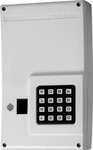
8 Technical features Power supply Standby current Operating current Pulse length for alarm channels (L1 and L2) Tamper line Pause between successive calls Pause between call attempts Dimensions (W*H*D) Weight (without battery) 13.8 V 15 ma 250 ma 0.3 s 500 ma - 24 V 5 s 60 s 132*220*62 mm 1.2 Kg Figure 2 Front panel parts. 8 Telephone dialler B-TEL99
9 Parts PART N. DESCRIPTION 1 Screws (4) to secure front panel to backplate. 2 Microphone for message recording. 3 LED display. 4 Alphanumeric telephone type keypad. 5 Holes (4) for backplate mounting (Ø 5 mm). 6 Loudspeaker for message playback. 7 Compartment for 12 V, 1.2 Ah battery (not supplied). 8 Cable passage (Ø 30 mm). 9 Battery connectors. 10 Hole for microswitch screw. 11 Tamper switch on backplate (optional). Figure 3 Backplate parts. INTRODUCTION 9
10 PART N. 12 Reset button. 13 Tamper switch. 14 Connection terminal board. 15 Loudspeaker connection. 16 DESCRIPTION Jumper for activation mode setting: > actuated by positive drop (default) ; > actuated by negative command. Figure 4 PCB parts. 10 Telephone dialler B-TEL99
11 INSTALLATION Mounting Before installing the B-TEL99 please note the following. To allow easy access to the keypad and microphone, and for an adequate view of the display, the B-TEL99 should be installed at a height of about 160 cm. Before drilling the stop holes, check for water pipes and electrical cables. Lay the cables for the B-TEL99 and its devices, and proceed as follows (see the illustrations on pages 8 and 9). Remove the front panel by unscrewing the screws 1. ATTENTION When the tamper switch is connected to the corresponding tamper line of a control panel, removal of the front panel, for repair or maintenance, will cause a false alarm. Therefore, it is necessary to disarm the control panel (according to the instructions in the control panel manual) before removing the front panel of B-TEL99. Pass the cables through the cable passage 8 then mount the B-TEL99. Description of the terminals 1-2 [L.E.] External telephone line. Connect the external telephone line to terminals 1-2[L.E.]. The B-TEL99 must be connected before all other line-sharing devices. Connect line-sharing telephone devices to terminals 3-4 [L.I.]. In accordance with regulation requirements, terminals 1-2[L.E.] must be connected to the telephone line by means of a telephone plug or by a telephone. ATTENTION Do not connect telephone devices parallel to terminals 1-2 [L.E.]. 3-4 [L.I.] Internal telephone line. These terminals should be used for the connection of line-sharing devices (switchboard, telephone, fax, modem, etc.). In the event of an alarm, the B-TEL99 will hook the telephone line until the programmed alarm cycle/s have been completed. 5 [ ] Ground. INSTALLATION 11
12 ATTENTION To comply with the telephone network safety standards, and protect the B-TEL99 from overvoltage on the telephone line, terminal 5[ ] must be connected to Ground of the electrical circuit. 6-7 [AS] Tamper. These normally closed terminals must be connected to the tamper switch/es 13 (on-board), and 11 (not supplied). The tamper switch 13 opens the circuit when the front panel of the B-TEL99 is removed. The optional tamper switch 11 (installed on the backplate, by request) opens the circuit when the B-TEL99 is pulled off the wall. These terminals must be connected to the tamper line of the security system control panel. 8[BA] - 9[ ] Stop Alarm. This terminal may be used to stop the alarm cycle/s, from a remote position or by means of a device (usually the control panel of a security system). To stop the alarm cycle/s connect this terminal momentarily to Negative. ATTENTION If terminal 8[B.A.] is used the alarm cycle will be stopped when Negative drops. 10[OUT] 11[L1] Line fault. This terminal signals fault on line. Terminal 10[OUT] is an opencollector output (NPN). Priority alarm channel. This terminal must be connected to Positive, when Positive drops the B-TEL99 actuates the alarm channel 1 calls. If alarm channel 1 (priority channel) goes into alarm status during the channel 2 cycle/s, the latter will be interrupted by the programmed channel 1 cycles, the remaining channel 2 cycle/s will restart when the channel 1 cycle/s end. Activation mode 12 [L2] Secondary alarm channel. This terminal is for alarm channel 2 activation. When alarm channel 2 is actuated the B-TEL99 starts the alarm channel 2 alarm cycle and sends the programmed messages to the assigned telephone numbers. When Positive drops on this terminal: both alarm channels will go into alarm status and will carry out the programmed cycles. The default programming is for Positive drop. This intrinsic safety function mode also protects against wire-cutting and blackout. If required, it is possible to program activation by Negative command, that is, by connecting the alarm channel to Negative. This function mode is useful in connections with open-collector alarm outputs. In all cases: if the alarm command is permanent, the B-TEL99 will carry out the alarm cycle once only; the B-TEL99 will complete the alarm cycle even when the alarm command is not permanent. To stop the alarm cycles in this case: 12 Telephone dialler B-TEL99
13 connect terminal 8[B.A.] to Negative (terminal 9) or enter the User Command PIN on the B-TEL99 keypad. 13[12] - 14[ ] Power supply. The B-TEL99 must be powered by 13.8 V 250 ma min. Basic connections The basic connections are necessary for the basic functions of the B- TEL99, and are illustrated in figure 5 (highlighted lines) on the following page. Figure 5 illustrates Alarm channel 1 connected to the normally closed contact (NC) of the control panel alarm relay. If the default programming (Positive drop) is to be changed to activation by Negative command, the Alarm channels must be connected to an output that goes to Ground (Negative) in the event of alarm (e.g. open-collector output). Auxiliary connections The auxiliary connections are not necessary to the basic functions of the B- TEL99, but offer further functions to this flexible appliance. The connections illustrated in figure 5 are described in the following paragraphs. Tamper connection Telephone-line tamper connection Device connection Stop alarm cycle/s connection The connection of the tamper terminals allows detection of tamper on the B-TEL99 container. These terminals should be connected in series to the tamper line of the alarm system, as shown in figure 5. The connection of the telephone-line tamper terminal signals telephoneline tamper or cutting. Terminal 10[OUT] is available for connections to a telephone-line switching device. Terminal 10[OUT] is an open-collector output (NPN). The B-TEL99 has two Alarm channels. Alarm channel 2 can be used for the connection to the alarm relay of the fire alarm system, to the Duress relay of the security system, or for the connection of a radio receiver (teleservice). The connection example is shown in figure 5: terminals [COM] and (NC) of the device relay must be connected to terminal 13[12] and to the secondary alarm channel 12[L2] of the B-TEL99. By connecting terminal 8[B.A.] to Negative, it will be possible to stop the alarm cycle/s. This feature is useful when: the dialler is difficult to reach, for security reasons; it is necessary to stop the alarm cycle/s when the Burglar system is disarmed. INSTALLATION 13
14 In the first case (dialler difficult to reach) connect a button or pulse lock between terminal 8[B.A.] and terminal 9[ ] as illustrated in figure 5. In the second case (to stop alarm cycle/s when the Burglar system is disarmed), terminal 8[B.A.] can be connected to terminal [ON] of the Burglar system (a terminal with Negative when the system is armed), or to terminal [OFF] of the Burglar system (a terminal with Positive when the system is disarmed). In the latter case, a 1k5, 1/4 W resistance between terminal [B.A.] and [ ]. Figure 5 Basic and auxiliary connections. 14 Telephone dialler B-TEL99
15 PROGRAMMING All the B-TEL99 parameters must be set during the programming phase. The parameters can be set according to installation and user requirements. The parameters are: Installer PIN Telephone numbers Alarm messages User Command PIN Message management Number of call cycles Message playback time Dialling type (DTMF or Pulse) Dial-tone check Voice answer detection Dial-tone type. Parameter programming is done on the B-TEL99 dialler keypad with the assistance of the display. It is possible to select the parameter and enter the required value by means of the keys, All the programmed data (including the alarm messages) are stored indefinitely on a non-volatile memory, even in the event of total power failure. Fast Keys The following keys have specific functions for all parameters. e Enter. This key confirms the entered parameter. f Quit. This key quits the operation in course, without modifying the current value. c Cancel. During the telephone number programming phase, this key cancels any wrong digits entered before pressing e. d Display. This key allows parameter viewing during the programming phase. For example, to view the set number of call cycles press: a b to select programming options; 2 to select the option number, in this case call cycles; d to view the set value. Check the entered value immediately after pressing e. At this point in the procedure it is possible to modify the value by entering the new value and pressing e to confirm. New values To modify a programmed parameter value, just enter the new value over the current value. PROGRAMMING 15
16
17
18 Programming chart The programming chart on the previous two pages will help the installer plan and carry out programming of the B-TEL99 dialler. The chart serves as a programming guide, as it shows (for each parameter) the keys to press (KEY column) the value to enter (DESCRIPTION column) and the factory default (DEFAULT column). It may be useful for the installer to make a copy of the chart for Installer records (useful when maintenance is required), and for future use as an installation plan for other systems. Blank spaces have been left at the top and bottom of the chart for Installer details. The chart has been designed to be kept inside a loose-leaf folder. Following is a short description of the items shown in the programming chart. CUSTOMER (details) Specify the User name, address, telephone and other details. SYSTEM No. Specify the system number or code. TESTED ON Specify the date of testing. CHANNEL 1 (2) Specify the event (Fire/Burglary) which activates alarm channel 1 (2) of the B-TEL99 dialler. CHANNEL 1 (2) TELEPHONE NUMBERS Specify the digits and pauses of the telephone numbers assigned to channel 1 (2), and customer details. INSTALLER PIN Specify the Installer PIN (if required). MESSAGES Specify the contents of the alarm messages. USER COMMAND PIN Specify the User Command PIN (if required). For security reasons the Installer PIN should not be known to the User, and vice versa. OPTION 1) MESSAGE MANAGEMENT Specify and highlight (use a flourescent highlighter pen) the programmed message management. OPTION 2) NUMBER OF CALL CYCLES Specify and highlight the programmed number of call cycles. OPTION 3) MESSAGE PLAYBACK TIME Specify and highlight the programmed message playback time. OPTION 4) DIALLING TYPE Specify and highlight the programmed dialling type. OPTION 5) DIAL-TONE CHECK Specify the programmed Dial-Tone check status (Enabled/Disabled). OPTION 6) VOICE ANSWER DETECTION Specify the programmed Voice Answer detection type. OPTION 7) DIAL-TONE TYPE Specify the programmed dial-tone type. 18 Telephone dialler B-TEL99
19 Installer PIN: Access to the programming phase To access the programming phase of the B-TEL99, open the control panel and press 12 on the board, or enter the default Installer PIN 11 and press e. The display 4 will show the symbol the required parameters. thus indicating ready status: enter If no key is pressed within 25 seconds the dialler will quit the programming phase automatically and return to standby status. To enter a new Installer PIN proceed as follows: Access the programming phase... 1 Press c twice. c c 2 Wait for the point on the display to start blinking slowly, and then enter the new PIN (up to 5 digits 0 through 9) Press e to enter and confirm. e PROGRAMMING 19
20 Telephone numbers The B-TEL99 can store 7 telephone numbers for each alarm channel: each number can have up to 15 digits and one or more pauses of 1 and/or 5 seconds (e.g. between the area code and the phone number). Default setting Programming The B-TEL99 has no default telephone numbers. To program the first number for alarm channel 1 proceed as follows: Access the programming phase... 1 Press a. a 2 Press Press 1 again. 1 4 Wait for the point on the display to start blinking slowly, and then enter the digits of the telephone number. Press a to enter pauses of 1 second, and b to enter pauses of 5 seconds. 0 7 a b Press c to stepback, and to cancel any wrong digits. c c c 6 Press e to enter and confirm the telephone number. e To store the remaining alarm channel 1 telephone numbers, follow steps 1 and 2 of the previously described procedure, but at step 3 press the key which corresponds to the required telephone number (2 through 7). 20 Telephone dialler B-TEL99
21 Channel 2 Display Erase To store alarm channel 2 telephone numbers, follow the entire procedure for alarm channel 1, but at point 2 press key 2. To view the stored telephone numbers, follow steps 1, 2 and 3 of the telephone number programming procedure, and then press d to display, in order, the digits of the telephone number in the selected position; any 1 second pauses will be indicated by and 5 second pauses by. If the selected position is empty (no number) the display will show. To erase a stored telephone number follow steps 1, 2 and 3 of the telephone-number programming procedure, and then press e to confirm. Alarm messages The Alarm messages are sent to the programmed telephone numbers. The B-TEL99 can store: Two Dedicated Messages (16 seconds per message), one for each alarm channel; A Long Common Message (32 seconds) for both channels, according to the setting of option n. 1 (see "OPTIONS"). A Short Common Message (16 seconds) for both alarm channels 2 brief dedicated messages (8 seconds per message), one for each alarm channel (see "OPTIONS"). Default setting The B-TEL99 message memory is empty (no default setting). Figure 6 Alarm message: graphic illustration (see option n. 1) PROGRAMMING 21
22 Long Common Message - Short Channel 1 Message - Brief Dedicated Channel 1 Message The alarm channel 1 message/s is/are sent to the programmed telephone numbers (max. 7), when the alarm channel 1 cycle is triggered. Record To record an alarm message for alarm channel 1 proceed as follows: Access the programming phase... 1 Press b. b 2 Press b again. b 3 Press Press e to start recording. e 5 Stand close to the microphone 5 (at approx.10 cm.) and, for best recording results, record the message in a deep tone of voice. *If option "1" is programmed as "Long Common Message" (common to both channels) the maximum recording time will be 32 seconds. In the event of an alarm, the same message will be sent for alarm channel 1 and alarm channel 2. If option "1" is programmed as "Two Dedicated Messages" the maximum recording time will be 16 seconds. If option "1" is programmed as "Short Common Message2 brief dedicated messages" the maximum recording time will be 8 seconds. The message countdown will be shown on the display in divisions of ten and so forth (0 stands for 10)..... Playback To playback the alarm channel 1 message proceed as follows: Access the programming phase... 1 Press b. b 2 Press 1 to select the alarm channel 1message. 1 3 Press e to start playback. e 22 Telephone dialler B-TEL99
23 Alarm Channel 2 Short Message - Brief Dedicated Channel 2 Message The alarm channel 2 message is sent to the programmed telephone numbers when the alarm channel 2 cycle is triggered. Record Playback To record the alarm channel 2 message follow the entire recording procedure for the alarm channel 1 message, but at step 3 press key 2. If option "1" is programmed as "Long Common Message" (common to both channels), it will not be possible to record a message for channel 2. If option "1" is programmed as "Two Dedicated Messages" the maximum recording time will be 16 seconds. If option "1" is programmed as "Short Common Message 2 brief dedicated messages" the maximum recording time will be 8 seconds. To playback the alarm channel 2 message/s follow the entire playback procedure for the alarm channel 1 message/s, but at step 2 press key 2. Short Common Message If option "1" is programmed as "Short Common Message 2 brief dedicated messages", the Short Common Message will be sent to the programmed telephone numbers, in the event of an alarm on either alarm channel 1 or 2. Record Playback To record the "Short Common Message" follow the recording procedure of the alarm channel 1 message, but at step 3 press key 3. If option "1" is programmed as "Long Common Message" (common to both channels) or "Two Dedicated Messages", it will not be possible to access this phase. If option "1" is programmed as "Short Common Message 2 brief dedicated messages", the maximum recording time will be 16 seconds. To playback the "Short Common Message" follow the playback procedure of the alarm channel 1 message, but at step 2 press key 3. User Command PIN The User Command PIN can stop the programmed B-TEL99 call cycle/s during an alarm status, and can be used on the B-TEL99 keypad and on the kepad of the telephone called by B-TEL99 (see "Stop Alarm"). Default setting The B-TEL99 default PIN is 22. PROGRAMMING 23
24 New PIN To program a new PIN proceed as follows: Access the programming phase... 1 Press c. c 2 Enter the new PIN (up to 5 digits 0 through 9) Press e to enter and confirm. e User Command fast key To create a User Command fast key, press c then e consecutively, in this way, in the event of an alarm all the enabled alarm sequences can be stopped by simply pressing e. Options The eight programmable options are: 1) Alarm Message Management; 2) Number of Call Cycles; 3) Playback Time; 4) Dialling Type; 5) Dial-Tone Check; 6) Voice Answer Detection; 7) Dial-tone type; 8) RESERVED OP- TION Time Adjustment for Pulse Dialling. Option 1) Message Management Value [1] = Long Common Message When 1 is selected the B-TEL99 will assign the Long Common Message (32 seconds) to both alarm channels. Value [2] = Two Dedicated Messages When 2 is selected the B-TEL99 will assign a Dedicated Message to each alarm channel (16 seconds per message). Value [3] = Short Common Message 2 brief dedicated messages When 3 is selected the B-TEL99 will assign the Short Common Message (16 seconds) to both alarm channels, and a brief dedicated message to each alarm channel (8 seconds per message). In the event of an alarm on alarm channel 1, programmed with value 3, the messages recorded by means of commands b-b-1-e will be sent, that is, the brief dedicated message (8 seconds) assigned to alarm chan- 24 Telephone dialler B-TEL99
25 nel 1; b-b-3 e the Short Common Message assigned to both alarm channels (16 seconds). Default setting The default setting is 2. Access the programming phase... 1 Press a. a 2 Press b. b 3 Press Press 1, 2 or 3, for example Press e to confirm and quit. e Default setting Option 2) Number of call cycles The call cycle option establishes the number of times the call cycle must be repeated. If alarm channel 1 goes into alarm status during the alarm channel 2 cycles, the latter will be interrupted by the programmed cycles for alarm channel 1 (priority channel), the remaining alarm channel 2 cycles will restart when alarm channel 1 cycles end. The B-TEL99 may be programmed to carry out 1, 2, 3, 4 or 5 call cycles. The default setting is 4 call cycles. To set the required number of call cycles proceed as follows. Access the programming phase... 1 Press a. a 2 Press b. b 3 Press 2 (option number). 2 4 Enter the required number of call cycles by pressing the corresponding key (1 to 5), for example Press e to confirm and quit. e PROGRAMMING 25
26 Default setting Option 3) Message playback time The message playback time option establishes the length of time (20, 40, 60 or 80 seconds) that the message must run for each telephone number. The message playback time should not be confused with the alarm message length, in fact, the latter is specified in option 1. The above value (length in seconds) will allow the message to be played several times. If option 1 is set as "Short Common Message 2 brief dedicated messages", and value 3 is set, the message length will be 816=24 seconds, and will run for 60 seconds, that is, two and a half times: 60:24= 2.5 times. The default message playback time is 40 seconds. To set the message playback time proceed as follows. Access the programming phase... 1 Press a. a 2 Press b. b 3 Press Enter the required message playback time by pressing one of the following keys: 1 = 20 s; 2 = 40 s; 3 = 60 s; 4 =80 s. If 40 seconds is required select Press e to confirm and quit. e Option 4) Dialling type It is possible to select pulse or DTMF dialling, according to the local dialling type, however, when possible select DTMF as it is faster than pulse dialling. Default setting The default setting is for DTMF. 26 Telephone dialler B-TEL99
27 To set the required dialling type proceed as follows. Access the programming phase... 1 Press a. a 2 Press b. b 3 Press 4 (option number). 4 4 Select the required dialling type by pressing one of the following keys: 1 = pulse dialling; 2 = DTMF dialling. If pulse dialling is required select Press e to confirm and quit. e Default setting Option 5) Dial-tone check When this option is disabled, the B-TEL99 will dial the numbers, assigned to the alarm channel in alarm status, without checking for the dial tone. If, however, this option is enabled, the B-TEL99 will dial the programmed numbers only when the dial-tone is detected, otherwise, it will release the telephone line and restart the alarm cycle with the same telephone number: after 4 attempts the B-TEL99 will abandon the telephone number and step to the successive number. This option must be disabled during the test phase (telephone line disconnected), and also when the B-TEL99 is connected to telephone networks with non-standard tones. The default setting is 1 "Disabled". To enable/disable proceed as follows. Access the programming phase... 1 Press a. a 2 Press b. b 3 Press Set the dial-tone check as required by pressing one of the following keys: 1 = Disabled 2 = Enabled 1 or 2 5 Press e to confirm and quit. e or PROGRAMMING 27
28 Option 6) Voice answer detection This option may have 3 values: Value [1]: Voice answer detection enabled without redialling of successful calls during the successive cycles. For example, if alarm channel 2 goes into alarm status, and is set for 3 call cycles, the B-TEL99 will call the first enabled telephone number assigned to alarm channel 2. With this function mode, if the first telephone number dialled is successful it will not be dialled during the successive call cycle. Value [2]: Voice answer detection enabled with redialling of successful calls. If the number of call cycles (option 2) is set as 1 there will be no difference between the two above mentioned settings. Value [3]: Voice answer detection disabled with 5 second message delay after dialling. Default setting Voice answer detection enabled without redialling of successful calls (value 1). To set the "Voice answer detection" option proceed as follows. Access the programming phase... 1 Press a. a 2 Press b. b 3 Press 6 (option number). 6 4 Select the required setting as follows: 1 = Voice answer detection enabled without redialling of successful calls; 2 = Voice answer detection enabled with redialling of successful calls; 3 = Voice answer detection disabled. If 1 is selected Press e to confirm and quit. e 28 Telephone dialler B-TEL99
29 Default setting Option 7) Dial-tone type It is possible to select [1]: Italian territory dial tone; [2]: Italian territory dial tone and continuous tone. This option is active when 2 (dial-tone check enabled) is selected for option 5. The default setting is [2]: both tones recognised. Select the dial-tone type as follows. Access the programming phase... 1 Press a. a 2 Press b. b 3 Press 7 (option number). 7 4 Select the dial-tone type: 1 = Italian dial tone only; 2 = Italian and continuous tone. 1 or 2 or 5 Press e to confirm and quit. e Activation mode Default setting By means of the jumper 16 it is possible to program B-TEL99 activation by positive drop or negative command. The default setting is activation by positive drop. To set the activation mode proceed as follows: remove the four screws 5 and the cover of the B-TEL99; position the jumper 16 between pins 1 and 2 for activation by positive drop; position the jumper 16 between pins 2 and 3 for activation by negative command. PROGRAMMING 29
30 Logger The B-TEL99 logger registers the last 255 outgoing calls (events). View Logger To view and scroll the last 255 events, starting from the most recent and moving backwards in order, proceed as follows: Access the programming phase... 1 Press d. d 2 Press 1 or 2 to scroll the logger sequence. 1 Keys 1 and 2 function as scroll keys: key 1 scrolls the events from the last (most recent) to the first, key 2 scrolls the events from the first to the last (most recent). Each event (number dialled) shows: the trigger channel (1 or 2); the telephone number called (1-7), and the call result, which may be: 0 = Successful call 1 = Line trouble or busy before dialling 2 = Line busy after dialling 3 = No answer Clear Logger To clear the event logger during viewing: press c twice; the logger will be cleared completely, and the B-TEL99 will step back to the programming phase. If access to the empty logger is requested e will be shown on the display. The B-TEL99 logger is completely empty before installation. Figure 7 Logger: use of keys [1] and [2]. 30 Telephone dialler B-TEL99
31 QUICK GUIDE The B-TEL99 requires little user intervention: the only manual intervention that may be required is the Stop alarm cycle/s command. The user may also change the programmed parameters of the B-TEL99 (see "Programming"). ATTENTION In the event of an alarm status, all telephone devices connected after the B-TEL99 will be isolated until the end of the programmed call cycle/s. When the alarm cycles end or are stopped, the telephone line will be released. Stop Alarm In the event of false alarms, the alarm cycle/s can be stopped in the following ways. From keypad By entering the User Command PIN followed by e. If, for example, the User Command PIN is press the corresponding keys followed by e: all the alarm cycle/s will be stopped immediately. To check that the B-TEL99 is disarmed (after a stop alarm cycle/s command). Press any key on the keypad; the display should remain blank, if not, repeat the stop alarm procedure, as above. Auxiliary command Alarm cycle/s can also be stopped by connecting terminal [B.A.] to an electric lock, a control panel, a radio receiver or other such device. Ask your installer for this option. Stop Alarm cycles via telephone To stop the alarm cycle/s via remote telephone, dial the User Command PIN and press [#] on the telephone keypad, before the dialler call ends. The [#] key corresponds to e on the B-TEL99. This operation is possible on DTMF telephones only. QUICK GUIDE 31
32 Listen-in Auxiliary To Listen-in on the protected ambient (via the remote telephone called by the dialler) proceed as follows. Enter the User Command PIN then press [*]. To stop the alarm cycle/s during remote Listen-in, enter the User Command PIN followed by [#], before the dialler call ends. The initial Listen-in time is 40 seconds. Press [*] at any point in the message to refresh (for a further 40 seconds) the Listen-in time. The B-TEL99 has an auxiliary command which stops the alarm cycle/s, this can be connected to an electric lock, burglar control panel, radio receiver or other similar devices. The installer will enable this command if required. ATTENTION Qualified persons only should install and program the B-TEL99, if proper functioning is to be guatanteed.
BENTEL SECURITY srl reserves the right to modify the technical specifications of this product without prior notice.
 BENTEL SECURITY srl reserves the right to modify the technical specifications of this product without prior notice. via Florida - Z.I. Valtesino - 63013 GROTTAMMARE (AP) - ITALY USER MANUAL: Digital communicator
Voice Board. Installation and Programming Guide. Runner 4/8,PowerWave 4/8/16 &, Elite64. Add-on Board For Storing Recorded Voice Messages
 ELECTRONIC ENGINEERING LTD. Voice Board Runner 4/8,PowerWave 4/8/16 &, Elite64 Add-on Board For Storing Recorded Voice Messages And listen-in. Installation and Programming Guide. P/N 7101372 Rev. C V.K
Ref. 1067/024 Ref. 1067/032A Ref. 1067/052A
 DS1067-062C Mod. 1067 LBT20063 REMOTE CONTROLLABLE ALARM CONTROL PANELS Ref. 1067/024 Ref. 1067/032A Ref. 1067/052A USER MANUAL TABLE OF CONTENTS INTRODUCTION... 6 1 CONTROL DEVICES... 7 1.1 1067/022 keypad
Ref.1067/032 Ref.1067/042
 DS1067-033A Mod. 1067 LBT8631 BUS CONTROL PANEL 8/32 INPUTS Ref.1067/032 Ref.1067/042 USER MANUAL TABLE OF CONTENTS 1 PREFACE... 5 2 COMMAND DEVICES... 6 2.1 1067/021 DISPLAY KEYPAD... 6 2.2 ELECTRONIC
ADE Gen4. Speech Dialler Engineering Information. Description. Features
 ADE Gen4 Speech Dialler Engineering Information Description The Informa is a Speech Dialler for use with intruder alarm systems. When the control panel recognises an alarm it triggers the Informa. The
2000 Series. Program Entry Guide. Control Panels
 2000 Series EN Program Entry Guide Control Panels 2000 Series Program Entry Guide About This Manual EN 2 About This Manual This guide describes the programming parameters available to the 2000 Series Control
NESS 5000 SERIES DIALLER
 NESS 5000 SERIES DIALLER INSTALLATION MANUAL This manual is designed to provide the installation instructions on the NESS SECURITY PRODUCT'S 5000 SERIES Dialler. For complete details on the warranty or
Version 1.03 January-2002 USER S MANUAL
 Version 1.03 January-2002 1 USER S MANUAL 2 Version 1.03 January-2002 System Details CUSTOMER:...... PHONE:... FAX:... INSTALLED BY:...... PHONE:... FAX:... MAINTENANCE & SERVICE:...... PHONE:... FAX:...
80 CHANNELS WIRELESS RECEIVER WITH LCD DISPLAY M1.1.1-Hx.x-F1.1-ENG [AN] [SPV] MADE IN ITALY INSTALLATION AND USE MANUAL
![80 CHANNELS WIRELESS RECEIVER WITH LCD DISPLAY M1.1.1-Hx.x-F1.1-ENG [AN] [SPV] MADE IN ITALY INSTALLATION AND USE MANUAL](/thumbs/72/67367199.jpg "80 CHANNELS WIRELESS RECEIVER WITH LCD DISPLAY M1.1.1-Hx.x-F1.1-ENG [AN] [SPV] MADE IN ITALY INSTALLATION AND USE MANUAL") RX808-LCD 80 CHANNELS WIRELESS RECEIVER WITH LCD DISPLAY 14.12-M1.1.1-Hx.x-F1.1-ENG [AN] [SPV] MADE IN ITALY INSTALLATION AND USE MANUAL WARNINGS Installation: This device must be installed only by qualified
RX808-LCD 80 CHANNELS WIRELESS RECEIVER WITH LCD DISPLAY 14.12-M1.1.1-Hx.x-F1.1-ENG [AN] [SPV] MADE IN ITALY INSTALLATION AND USE MANUAL WARNINGS Installation: This device must be installed only by qualified
ALARM SYSTEM USER S MANUAL Rev
 ALARM SYSTEM USER S MANUAL Rev.06 890-00011 Manufacturer: Viatron Electronics 3514 1st Street, St-Hubert (Quebec) Canada J3Y 8Y5 WARNINGS the warranty can be void if the Agri-Alert 2400 is used in a manner
DL150 DOWNLOADABLE CONTROL COMMUNICATOR INSTALLATION MANUAL
 DL150 DOWNLOADABLE CONTROL COMMUNICATOR INSTALLATION MANUAL TABLE OF CONTENTS 1. GENERAL DESCRIPTION... 2 2. STANDARD AND OPTIONAL PARTS LIST... 2 3. FEATURE DEFINITIONS... 3 4. TERMINAL DRAWING AND SPECIAL
Elite 16D Version 16 Zone Controller Arrowhead Alarm Products Ltd. Operating Guide. Proudly Designed and Manufactured in New Zealand
 6 Elite 16D Version 16 Zone Controller Arrowhead Alarm Products Ltd Operating Guide 1 Proudly Designed and Manufactured in New Zealand CONTENTS Page No. INTRODUCTION 3 About your Alarm 3 OPERATING YOUR
RANGER 8600 DOWNLOADABLE CONTROL COMMUNICATOR INSTALLATION MANUAL
 RANGER 8600 DOWNLOADABLE CONTROL COMMUNICATOR INSTALLATION MANUAL TABLE OF CONTENTS GENERAL DESCRIPTION... 2 STANDARD AND OPTIONAL PARTS LIST... 2 PARTS DIAGRAM... 3 TERMINAL DRAWING AND SPECIAL NOTES...
Control Panel. Operators Manual TO SUIT AS216 KEYPAD. AS216-OM-6.2. Advanced Digital Controls
 Control Panel Operators Manual TO SUIT AS216 KEYPAD AS216-OM-6.2 Ultra-16 Control Panel AS216 OPERATORS MANUAL Copyright 2002 by NZ Ltd Auckland, New Zealand Document Part Number: This document is provided
PERMACONN PM1030 Includes DI300. Installation Manual
 PERMACONN PM1030 Includes DI300 Installation Manual Radio Data Comms Unit 5/20-30 Stubbs Street Silverwater NSW 2128 Telephone: 02 9352 1777 Facsimile: 02 9352 1700 Introduction The PERMACONN system provides
CC408. Quick Reference Guide Solution 880
 CC408 EN Quick Reference Guide Solution 880 CC408 Quick Reference Guide Notices EN 2 Copyright Notice Unless otherwise indicated, this publication is the copyright of Bosch Security Systems Pty Ltd ( Bosch
RANGER 7600 DOWNLOADABLE CONTROL COMMUNICATOR INSTALLATION MANUAL
 RANGER 7600 DOWNLOADABLE CONTROL COMMUNICATOR INSTALLATION MANUAL TABLE OF CONTENTS 1. TABLE OF CONTENTS... P.1 2. GENERAL DESCRIPTION... P.2... 3. STANDARD AND OPTIONAL PARTS LIST... P.2... 4. FEATURE
Ref. 1067/024 Ref. 1067/032A Ref. 1067/052A
 DS1067-064D Mod. 1067 LBT20065 REMOTE CONTROLLABLE ALARM CONTROL PANELS Ref. 1067/024 Ref. 1067/032A Ref. 1067/052A PROGRAMMING MANUAL TABLE OF CONTENTS INTRODUCTION... 7 1 CONTROL DEVICES... 8 1.1 1067/022
AGRI-ALERT 9600 ALARM SYSTEM USER MANUAL
 AGRI-ALERT 9600 ALARM SYSTEM USER MANUAL M 890-00279 rev. 14 K 895-00004 rev. 00 Manufacturer: Viatron Electronics 5200, Armand-Frappier St-Hubert (Quebec) Canada J3Z 1G5 WARNINGS The warranty can be void
INSTALLATION MANUAL.
 INSTALLATION MANUAL FC200 - FC200/S - FC200/SL : Hereby, Bentel Security, declares that the above mentioned Control Panels are in compliance with the essential requirements and other relevant provisions
D6500 reports are shown in typewriter style letters. For example, AC FAILED indicates the report sent when the panel reports an AC power failure.
 Notice The material and instructions covered in this manual have been carefully checked for accuracy and are presumed to be reliable. However, Radionics, Inc. assumes no responsibility for inaccuracies
AT60 AUTO DIALLER User Guide
 AT60 AUTO DIALLER User Guide Power on LED MIC Power on LED MIC 1 2 3 4 5 6 7 8 9 REC/PLAY 0 STORE M1 M2 M3 Table of Contents I. Overview 3 II. Installation 4 III. Initialize the Dialer 5 IV. Using the
EC-P Zone Intruder Alarm System
 EC-P10 10-20 Zone Intruder Alarm System Installation Manual Contents 1. System Overview... 4 System Configuration... 4 Control Panel... 5 Remote Keypads... 5 EC-LED Remote Keypad... 5 EC-LCD Remote Keypad...
Solution 862 Installation Manual ISSUE 1.30
 Solution 862 Installation Manual ISSUE 1.30 MA406I This page has been included for you to cut out and insert into the spine of the folder Solution 862 Installation Manual ISSUE 1.30 (61-2) 9672 1233 Solution
AXI LED USER MANUAL (REV. 1.0)
") Security & Home Automation System AXI LED USER MANUAL (REV. 1.0) CONTENTS PREFACE FEATURES LED KEYPAD OUTLOOK 1.0 LIGHT INDICATION 1 2 4 6 CHAPTER 1: ALARM SYSTEM CONTROL 1.0 USING LED KEYPAD 1.0.1 ARMING
Security & Home Automation System AXI LED USER MANUAL (REV. 1.0) CONTENTS PREFACE FEATURES LED KEYPAD OUTLOOK 1.0 LIGHT INDICATION 1 2 4 6 CHAPTER 1: ALARM SYSTEM CONTROL 1.0 USING LED KEYPAD 1.0.1 ARMING
1. Introduction. 2. Product overview
 1. Introduction The AG400011 GSM Alarm panel is a control panel that is compatible with other H-net security devices from Everspring, such as wireless sensors, remote keyfobs, tags, and keypad. With this
Wireless Keypad GKP-S8M
 Wireless Keypad GKP-S8M User manual Contents Congratulations on your purchase of this Honeywell wireless keypad. To make the best out of your equipment we advise you to read this manual carefully. This
Alarm Control Panel WIC-16Z4P WIC-5Z2P. Installation & Operation User Manual
 WIC-16Z4P WIC-5Z2P Installation & Operation User Manual Page : 1/34 INDEX # Function Page 1 Abort Current Communication and Clear Reporting Queue (*59) 13 2 Abort Current Communications (*59) 10 3 Account
DL100 DOWNLOADABLE CONTROL COMMUNICATOR INSTALLATION MANUAL
 DL100 DOWNLOADABLE CONTROL COMMUNICATOR INSTALLATION MANUAL TABLE OF CONTENTS 1. GENERAL DESCRIPTION...P.2 2. STANDARD AND OPTIONAL PARTS LIST...P.2 3. FEATURE DEFINITIONS...P.3 4. TERMINAL DRAWING AND
Solution-16/ Solution-16 Safecom Installation Manual ISSUE 2.10
 Solution-16/ Solution-16 Safecom Installation Manual ISSUE 2.10 MA880I Solution-16/ This page has been included for you to cut out and insert into the spine of the folder Solution-16 Safecom Installation
ELECTRONICS LINE S TECHNICAL SUPPORT DEPARTMENT: (972)
") Summit 3208GLD Installation, Operation and Programming Electronics Line (E.L.) Ltd. www.elecline.com ELECTRONICS LINE S TECHNICAL SUPPORT DEPARTMENT: (972)-3-9211110 Electronics Line (E.L.) Ltd. reserves
Summit 3208GLD Installation, Operation and Programming Electronics Line (E.L.) Ltd. www.elecline.com ELECTRONICS LINE S TECHNICAL SUPPORT DEPARTMENT: (972)-3-9211110 Electronics Line (E.L.) Ltd. reserves
Burglar-alarm unit. User manual. Part. U3499A - 11/08-01 PC
 Burglar-alarm unit User manual 5739 34 5739 35 Part. U3499A - 11/08-01 PC Contents 1. Introduction 5 The Burglar-alarm Unit 6 The keypad 7 Navigation keys 7 The display 7 Initial page 7 In case of an
WIRELESS ALARM SYSTEM WITH TELEPHONE AUTO DIALER
 BAT.LOW AC WIRELESS ALARM SYSTEM WITH TELEPHONE AUTO DIALER THE SYSTEM THAT CALLS YOU! Our WIRELESS ALARM SYSTEM WITH TELEPHONE AUTO DIALER is designed to allow you to create your own security system.
A1UL PERS. Personal Emergency Response System. For Technical Support Please Contact Your Service Provider Or Distributor
 A1UL PERS Personal Emergency Response System TABLE OF CONTENTS 1. READ THIS FIRST... 1 2. SYSTEM OVERVIEW.. 1 3. COMPONENTS 2 4. UNIT OPERATION! Standby Mode.. 3! Emergency Activation. 3! Answering Incoming
Wireless Keypads LKP(E)S8M Series
S8M Series") Wireless Keypads LKP(E)S8M Series User manual Contents Congratulations on your purchase of this Honeywell wireless keypad. To make the best out of your equipment we advise you to read this manual carefully.
Wireless Keypads LKP(E)S8M Series User manual Contents Congratulations on your purchase of this Honeywell wireless keypad. To make the best out of your equipment we advise you to read this manual carefully.
All-In-One Wireless Security System V3.2 Programming Guide. Model # MG6130 / MG6160
 All-In-One Wireless Security System V3.2 Programming Guide Model # MG6130 / MG6160 We hope this product performs to your complete satisfaction. Should you have any questions or comments, please visit www.paradox.com
Thank you for choosing Ideal Security s Home Security System with Telephone Dialer.
 SK618 WIRELESS ALARM SYSTEM WITH AUTO DIALER OWNER'S MANUAL Thank you for choosing Ideal Security s Home Security System with Telephone Dialer. If at any time during your installation you have any questions
Elite S Version 8-16 Zone Controller Arrowhead Alarm Products Ltd. Operating Guide. Proudly Designed and Manufactured in New Zealand
 9 Elite S Version 8-16 Zone Controller Arrowhead Alarm Products Ltd Operating Guide Proudly Designed and Manufactured in New Zealand 1 CONTENTS Page No. INTRODUCTION About your Alarm 3 3 OPERATING YOUR
Contents. Glossary
 Contents Glossary ------------------------------------------------------------------------------------------------------ 6 1. Introduction to the IDS 1632 -------------------------------------------------------------
Installation and Programming manual INSTALLATION MANUAL E PROGRAMMING INSTALLAZIONE PROGRAMMAZIONE
 SELF-POWERED S I R E N A A U SOUNDER/FLASHER T O A L I M E N T A T A FOR P E R OUTDOOR E S T E R NUSE O INSTALLATION MANUALE AND DI PROGRAMMING INSTALLAZIONE MANUAL E PROGRAMMAZIONE 1 Table of contents
RANGER 8980E DOWNLOADABLE CONTROL COMMUNICATOR INSTALLATION MANUAL
 RANGER 8980E DOWNLOADABLE CONTROL COMMUNICATOR INSTALLATION MANUAL TABLE OF CONTENTS GENERAL DESCRIPTION...2 STANDARD AND OPTIONAL PARTS LIST...2 FEATURE DEFINITIONS...3 TERMINAL DRAWING AND SPECIAL NOTES...4
Solution 6+6 Wireless - AE Installation Manual ISSUE 1.10
 Solution 6+6 Wireless - AE Installation Manual ISSUE 1.10 MA660I Solution 6+6 This page has been included for you to cut out and insert into the spine of the folder Wireless AE Installation Manual ISSUE
Solution 6+6 Wireless On/Off Installation Manual ISSUE 1.20
 Solution 6+6 Wireless On/Off Installation Manual ISSUE 1.20 MA670I This page has been included for you to cut out and insert into the spine of the folder Solution 6+6 Wireless On/Off Installation Manual
Summit 3208GLD USER MANUAL. Electronics Line
 Summit 3208GLD USER MANUAL Electronics Line Table of Contents 1: Introduction... 2 2: Overview... 3 3: Keypad Functions... 4 3.1: Keypads... 4 3.2: 3108 LCD Keypad Layout... 4 4: Basic System Operation...
HEXA PROGRAMMING: STREAMLINED SECTION PROGRAMMING
 -961212-0004 SOFTWARE VERSION 3.10 CONTROL PANEL RESET: Installer lock must be unlocked. ( 058: enter any value other than 147) Power down reset (1) Remove battery and AC to power down the unit. (2) Connect
Control/Communicator Installation Manual
 DAS NETWORX NX-12 Control/Communicator Installation Manual General Description...2 Ordering Information...2 Option Definitions...3 Programming the LED Code Pads...5 Programming the NX-12...9 Types of Programming
Elite 64 Version 64 Zone Controller Arrowhead Alarm Products Ltd. Operating Guide. Proudly Designed and Manufactured in New Zealand
 2 Elite 64 Version 64 Zone Controller Arrowhead Alarm Products Ltd Operating Guide Proudly Designed and Manufactured in New Zealand 1 CONTENTS Page No. INTRODUCTION 3 About your Alarm 3 OPERATING YOUR
Fire Burglary Instruments Inc. XL-2G Gold Control/Communicator Installation Training Seminar Rev. 5/96
 Fire Burglary Instruments Inc. XL-2G Gold Control/Communicator Installation Training Seminar Rev. 5/96 XL-2G Gold Product Overview 7 Zones (6 programmable + panic or keyswitch zone) Fast Loop Response
INSTALLATION MANUAL PC56O. Version 1.OA
 INSTALLATION MANUAL PC56O Version 1.OA TABLE OF CONTENTS INTRODUCTION 3 Features... 3 Specifications... 3 INSTALLATION 4 Mounting the Control Panel... 4 Mounting the Keypad... 4 Wiring... 5 Burglary Zone
Thank you for choosing Ideal Security s Home Security System with Telephone Dialer.
 SK618 WIRELESS ALARM SYSTEM WITH AUTO DIALER OWNER'S MANUAL Thank you for choosing Ideal Security s Home Security System with Telephone Dialer. If at any time during your installation you have any questions
TABLE OF CONTENTS. General Description Standard and Optional Parts List Feature Definitions Comments about the 8600E...
 5$1*(5( DOWNLOADABLE CONTROL COMMUNICATOR INSTALLATION MANUAL TABLE OF CONTENTS General Description... 2 Standard and Optional Parts List... 2 Feature Definitions... 3 Comments about the 8600E... 4 Terminal
Control Panel. 1.0 GENERAL SCOPE OF WORK Introduction... 2
 Architectural & Engineering Specifications Control Panel 1.0 GENERAL... 2 1.1 SCOPE OF WORK... 2 1.1.1 Introduction... 2 1.2 GENERAL CONDITIONS... 2 1.2.1 After-Sales Support... 2 1.2.2 Quality assurance...
BENTEL SECURITY declines all responsibility in the event of unauthorized intervention on the FireClass200 control panel.
 V4.2 BUI 0.1 061099 The FireClass200 is available in the following models: FC200 - Master panel with 4 A Linear power supply; FC200/S - Master panel with 2.5 A Switching power supply; FC200/SL - Slave
Using Your. Security System With LED Keypad S5030, S5031, S5032
 Using Your Security System With LED Keypad S5030, S5031, S5032 Contents 1 Overview Your Security System... 1 How Your Security System Works... 2 Your System's Programming... 3 Getting Used to Your System...
PERS-3600 PERSONAL EMERGENCY REPORTING SYSTEM INSTALLATION & OPERATION INSTRUCTIONS
 PERS-600 PERSONAL EMERGENCY REPORTING SYSTEM BY BY INSTALLATION & OPERATION INSTRUCTIONS (760) 8-7000 USA & Canada (800) -587 & (800) 9-0 Toll Free FAX (800) 68-0 www.linearcorp.com CONTENTS CONTROL AREA
Alarm Control Panel WIC-16Z4P WIC-5Z2P. User Instructions
 WIC-16Z4P WIC-5Z2P User Instructions Page : 2/14 INDEX # Function Page 1 Add a New User Code 11 2 Arm or Disarm All Areas or Disarm Selected Areas (Partitioned System) 8 3 Arming the System (Away Mode)
CC880/LP880, SC8016. Operators Guide Solution-16, Solution-16 Safecom
 CC880/LP880, SC8016 EN Operators Guide Solution-16, Solution-16 Safecom CC880/LP880, SC8016 Operators Guide EN 2 Copyright Notice Unless otherwise indicated, this publication is the copyright of Bosch
Powerwave Series. Technical Manual
 Powerwave Series Technical Manual 7 December 2001 1 INDEX INDEX.. P2 SPEECH MODULE. P6-9 DALLAS KEY/READER.. OUTPUT EXPANDER. P11 P10 NITE ARM KEYPAD. P11 PRINTER/PC INTERFACE. PROGRAMMING KEY. RX40 RECEIVER.
USER CODES. User Codes (1-6 digits) Access Levels + Access Levels. Time Control Address Address Address Address User 1 (Master)
 Access Levels + Access Levels. Time Control Address Address Address Address User 1 (Master)") User Codes (1-6 digits) Access Levels Access Levels + Time Control User 1 (Master) 1 1 2 3 25 49 73 0 User 2 2 26 50 74 0 User 3 3 27 51 75 0 User 4 4 28 52 76 0 User 5 5 29 53 77 0 User 6 6 30 54 78 0
User Codes (1-6 digits) Access Levels Access Levels + Time Control User 1 (Master) 1 1 2 3 25 49 73 0 User 2 2 26 50 74 0 User 3 3 27 51 75 0 User 4 4 28 52 76 0 User 5 5 29 53 77 0 User 6 6 30 54 78 0
Program version Alarm Control Panels PROGRAMMING GDAŃSK. versa_p_en 03/09
 Alarm Control Panels Program version 1.00 PROGRAMMING GDAŃSK versa_p_en 03/09 The SATEL's goal is to continually upgrade the quality of its products, which may result in alterations of their technical
User Manual. with LED Keypad. Alarm Control Panel CA10 plus (software version 4.7) GDAŃSK. ca10pldu_e 07/03
 GDAŃSK. ca10pldu_e 07/03") User Manual Alarm Control Panel CA10 plus (software version 4.7) with LED Keypad GDAŃSK ca10pldu_e 07/03 WARNING In order to avoid any operational problems with the control panel, it is recommended that
User Manual Alarm Control Panel CA10 plus (software version 4.7) with LED Keypad GDAŃSK ca10pldu_e 07/03 WARNING In order to avoid any operational problems with the control panel, it is recommended that
ANEP S-BOX EMERGENCY TELEPHONE FOR ELEVATORS.
 ANEP S-BOX EMERGENCY TELEPHONE FOR ELEVATORS www.anepanywhere.com SUMMARY 1 - TECHNICAL CHARACTERISTICS Page 4 1.1 - Technical characteristics 1.2 - Machine room Intercom and fireman until functionnality
System Introduction. 1.1 Specifications S E C T I O N 1
 System Introduction S E C T I O N 1 1.1 Specifications Control Panel Specifications Flexible Zone Configuration: 8 Fully Programmable Zones 37 Access Codes: 32 User, 1 System Master, 2 Partition Master
Training Manual with Bi-directional Wireless
 Training Manual with Bi-directional Wireless Installer Training Firmware Version 2.7x X16 Stock Code: 860-1-473-X16 X64 Stock Code: 860-1-864-XS 2 IDS X-Series Training v2.7 Contents Contents 3 X-Series
Operating instructions 2-channel code lock. Item No
 Operating instructions 2-channel code lock Item No. 1560346 Table of contents Page 1. Introduction...4 2. Explanation of symbols...4 3. Intended use...5 4. Delivery content...5 5. Safety instructions...6
SOFTWARE VERSION 2.20 CONTROL PANEL RESET:
 -961112-0002 SOFTWARE VERSI 2.20 CTROL PANEL RESET: Installer lock must be unlocked. ( 255: enter any value other than 147) Power down reset (1) Remove battery and AC to power down the unit. (4) Wait 3
Radionics D4112 Program Sheet
 Programming only by downloading, 5200 Programmer or 5100 "Wand" Programmer Plug programmer in and momentarily short Reset Pin to Terminal 25 to enable program mode 1. Account Account # I I I I I (0 to
User instructions EasyAlarm CONTROL
 LEITRONIC AG Swiss Security Systems TELEMONITORING / TELECONTROLLING SYSTEM User instructions EasyAlarm CONTROL Interface-Modul Potential free relay switch: 10..230V AC or DC AC-switch: max. 2A / 230V
CC488. Quick Reference Guide Solution Ultima 880
 CC488 EN Quick Reference Guide Solution Ultima 880 CC488 Quick Reference Guide Notices EN 2 Copyright Notice Unless otherwise indicated, this publication is the copyright of Bosch Security Systems Pty
Content. 1. Introduction to the IDS Features Installation and Wiring End-of-Line Resistors/Tamper per Zone...
 1 2 Content 1. Introduction to the IDS 805... 7 1.1 Features...7 2. Installation and Wiring...8 3. End-of-Line Resistors/Tamper per Zone...9 4. Connecting the Telephone Communicator...10 5. Programmable
3 User s settings. 3.3 Internal clock setting
 2.9 Subsystem arming In a large building a sub control panel can be enrolled to the JA-63. The subsystem reports all alarms and failures to the main system. The installer can program if the systems will
MEDI-CALL UNIT INSTALLATION MANUAL. Medi-Call V2.0 - V2.7 Installation Manual
 MEDI-CALL UNIT INSTALLATION MANUAL Medi-Call V2.0 - V2.7 Installation Manual Copyright SmartLink International Pty Ltd February 2006 475 Nepean Highway, Brighton VIC 3186 Australia Telephone: +61 3 9596
HELPY QUICK-TL GSM INTL
 Alarm system for elevators HELPY QUICK-TL GSM INTL QUICK GUIDE 04/02/16 DESCRIPTION A B C D E F G H I L M N O Connector for external LEDs Connector for built-in loudspeaker Built-in loudspeaker Connector
SPLIT-DECODED CONTROLLER
 SPLIT-DECODED CONTROLLER FOR HAA28XX SERIES SECURITY KEYPADS HAA2801 Programming & Installation Manual FOR ELECTRIC LOCK, INTER-LOCK AND SECURITY SYSTEM INSTALLATIONS VERSION: 11/2012 TABLE OF CONTENTS
HEXA PROGRAMMING: STREAMLINED SECTION PROGRAMMING
 48ESEP-01 SOFTWARE VERSION 3.10 CONTROL PANEL RESET: Installer lock must be unlocked. (Address 058: enter any value other than 147) Power down reset (1) Remove battery and AC to power down the unit. (2)
XR10 Command Processor Panel Programming Guide
 XR10 Command Processor Panel Programming Guide 10 Zone Burglary/Fire/Access Control Panel with Built-in Communicator Do Not Throw Away! This programming guide contains information you need to program and
The most user friendly Security Alarm System L S Section 1 Overview of System Section 2 Planning your Installation
 The most user friendly Contents Section 1 Overview of System 1.1 Kit Contents 1.2 Tools Required 1.3 System Features Security Alarm System L S 4 0 0 Section 2 Planning your Installation 2.1 Location of
PROGRAMMING GUIDE SPECTRA CONTROL PANELS V , 1725EX, 1728 AND 1728EX 1755, 1755EX, 1758, AND 1758EX
 PROGRAMMING GUIDE SPECTRA CONTROL PANELS V1.2 1725, 1725EX, 1728 AND 1728EX 1755, 1755EX, 1758, AND 1758EX TABLE OF CONTENTS HOW DO I PROGRAM THE SYSTEM?... 4 Single Digit Data Entry Method (Hexadecimal
System Introduction. 1.1 PC5015 Specifications S E C T I O N 1
 1.1 PC5015 Specifications System Introduction S E C T I O N 1 Flexible Zone Configuration: 8 Fully Programmable Zones 38 Access Codes: 32 User, 1 System Master, 2 Partition Master, 2 Duress and 1 maintenance
DYGIZONE GJD910 Lighting Controller & Enunciator
 DYGIZONE GJD910 Lighting Controller & Enunciator MASTER WIRING IDENTIFICATION Power up to the DygiZone and you will see: All the LED s (red,yellow,green and blue buttons) will flash All the LCD icons will
Agri-Alert 800 EZe Alarm System Owner s manual
 Agri-Alert 800 EZe Alarm System Owner s manual Read this guide carefully before using the alarm system. Manufacturer: Viatron Electronics 5200, Armand-Frappier St-Hubert (Quebec) Canada J3Z 1G5 WARNINGS
Series. NX-4-EUR Control Panel. Installation manual
 g GE Security NetworX TM Series NX-4-EUR Control Panel Installation manual CONTENTS CONTENTS...2 GENERAL INFORMATION...4 ORDERING INFORMATION...4 FEATURE DEFINITIONS...5 PROGRAMMING THE NX-4 KEYPADS...12
SOFTWARE VERSION 2.20 CONTROL PANEL RESET: Installer lock must be unlocked. (Address 255: enter any value other than 147)
") -961112-0003 SOFTWARE VERSI 2.20 CTROL PANEL RESET: Installer lock must be unlocked. ( 255: enter any value other than 147) Power down reset (1) Remove battery and AC to power down the unit. (4) Wait 3
-961112-0003 SOFTWARE VERSI 2.20 CTROL PANEL RESET: Installer lock must be unlocked. ( 255: enter any value other than 147) Power down reset (1) Remove battery and AC to power down the unit. (4) Wait 3
Independent Zone Control (I.Z.C.)
") Operation and Installation Guide Independent Zone Control (I.Z.C.) DELAYED INSTANT ARMED 1 2 3 4 7 5 6 8 9 * * fi Radionics R D279A Operation & Installation Guide 46456B Page 2 Copyright 2000 Radionics
Operation and Installation Guide Independent Zone Control (I.Z.C.) DELAYED INSTANT ARMED 1 2 3 4 7 5 6 8 9 * * fi Radionics R D279A Operation & Installation Guide 46456B Page 2 Copyright 2000 Radionics
The complete R&TTE Declaration of Conformity for each Panel can be found at
 USER GUIDE FC200 - FC200/S - FC200/SL - FC100: Hereby, Bentel Security, declares the above mentioned Control Panels to be in compliance with the essential requirements and other relevant provisions of
QUICK USER GUIDE. Alarm Control Panel
 Alarm Control Panel Firmware version 2.10 QUICK USER GUIDE The full version of User Manual and other manuals are available on CD included in the control panel delivery set or on the website www.satel.eu
CORNELL Emergency Response Systems
 CORNELL Emergency Response Systems Door Monitor Systems Series 1000 CORNELL Communications, Inc. Milwaukee, WI USA 800-558-8957 - www.cornell.com rev 6/04 A-1000 SERIES DOOR MONITOR OPERATION AND WIRING
NookBox Installation Guide Keypad. Installation Guide. NookBox Keypad (P / E )
") 1 Installation Guide NookBox Keypad (P119010 / E6309744) 2 NookBox Keypad (P119010 / E6309744) 3 Parts Identification 1. Active LED 2. Status LED 3. Fault Display LED 4. Arm Key 5. Home Key 6. Key Check
1 Installation Guide NookBox Keypad (P119010 / E6309744) 2 NookBox Keypad (P119010 / E6309744) 3 Parts Identification 1. Active LED 2. Status LED 3. Fault Display LED 4. Arm Key 5. Home Key 6. Key Check
VAP304 PRO INSTALLATION & OPERATION MANUAL
 VAP304 PRO INSTALLATION & OPERATION MANUAL Panic Fire Duress Program Bypass Report Chime Test Memory B A D C Program Chime Panic Duress Exit Fire Report Bypass Memory Test Reset Password Exit Reset Password
Premier Hazard STC Instructions
 PREMIER HAZARD Ltd Bessingby Industrial Estate Bridlington YO16 4SJ Tel: +44 (0) 113 239 1111 Fax: +44 (0) 113 239 1131 www.premierhazard.co.uk info@premierhazard.co.uk Premier Hazard STC Instructions
 Solution-6 Operators Manual Page 1 Preface Congratulations on selecting the Solution-6 security control system for your installation. So that you can obtain the most from your unit, we suggest that you
Quick Programmer s Manual
 Version 2.604 (31/03/05) p1 Quick Programmer s Manual 2005. Inner Range Pty. Ltd. Part Number: 630048V2 p2 Version 2.604 (31/03/05) TABLE OF CONTENTS. 1. PROGRAMMING FLOWCHART. The following flowchart
HEXA PROGRAMMING: STREAMLINED SECTION PROGRAMMING
 -961212-0004 SOFTWARE VERSI 3.10 CTROL PANEL RESET: Installer lock must be unlocked. (Address 058: enter any value other than 147) Power down reset (1) Remove battery and AC to power down the unit. (2)
Total Connect Box. User manual
 Total Connect Box User manual 1 Congratulations on your purchase of the Honeywell Total Connect Box security system. To make the best out of your system we advise you to read this manual carefully. This
PowerWave-16. Users Operating and Programming Guide Version P/N Rev. B N.A July 2002
 ELECTRONIC ENGINEERING LTD. PowerWave-16 16 zone Control panel Communicator Users Operating and Programming Guide Version 6.20 P/N 7121240 Rev. B N.A July 2002 Contents Introduction...4 Meet the Crow Alarm
Memcom + Emergency Telephone
 Memcom + Emergency Telephone Installation Guide Ref No. 453 901AU (GB) Version 4 + + Simple wiring for quick installation + + Integrated LCD display shows you what you have programmed + + All code based
EA-MINI / EA-MINI-V. LEITRONIC AG Swiss Security Systems
 4923 Table of contents Overview... 2 2 Applications... 3 2. Door-phone... 3 2.. Wiring... 3 2.2 Alarm dialler... 4 2.2. Wiring... 4 3 Mechanical fitting... 5 3. Retrofit solutions to existing elevators...
ELT-KLED EliteSuite LED Keypad Installation Manual
 ELT-KLED EliteSuite LED Keypad Installation Manual ELT-KLED EliteSuite Installation Manual PUBLICATION INFORMATION First Publication Draft Document Release Only Updated fire zone information Second Publication
DOLKPS1KB Programming & Installation Manual
 VANDAL RESISTANT BACK-LIT WEATHERPROOF ACCESS CONTROL KEYPAD WITH WIEGAND OUTPUT & DATA I/O DOLKPS1KB Programming & Installation Manual FOR ELECTRIC LOCK, INTER-LOCK AND SECURITY SYSTEM INSTALLATIONS DOLKPS1KB
SA 2650 Kit User Manual
 SA 2650 Kit User Manual Table of Contents 1. System Installation Planning 1 2. Device Introduction 3 3. Getting Started 6 4. System Default Setting 10 5. Connect2Home Application 11 6. System Information