DL100 DOWNLOADABLE CONTROL COMMUNICATOR INSTALLATION MANUAL
|
|
|
- Ginger Jordan
- 5 years ago
- Views:
Transcription
1 DL100 DOWNLOADABLE CONTROL COMMUNICATOR INSTALLATION MANUAL TABLE OF CONTENTS 1. GENERAL DESCRIPTION...P.2 2. STANDARD AND OPTIONAL PARTS LIST...P.2 3. FEATURE DEFINITIONS...P.3 4. TERMINAL DRAWING AND SPECIAL NOTES...P.4 5. TERMINAL DESCRIPTION...P.5 6. HOW TO PROGRAM THE DAS DL100...P.6 7. CODE PAD PROGRAMMING EXAMPLES...P.7 8. OPTIONAL #8950 PROGRAMMER EXAMPLE...P.7 9. REQUIRED PROGRAMMING INSTRUCTIONS...P COMMUNICATOR FORMAT SELECTION GUIDE...P OPTIONAL PROGRAMMING INSTRUCTIONS...P DOWNLOAD PROGRAMMING INSTRUCTIONS...P PROGRAMMING WORKSHEETS...P APPENDIX 1...P SPECIFICATIONS & WARRANTY...P.32 1
2 DAS DL100 INSTALLATION MANUAL General Description The Das DL100 is a versatile 6 zone up/downloadable security control, with a built-in digital communicator. Its microcomputer design gives some of the most versatile, yet easy to use features available for most security applications today. Each of the six zones can be programmed to be one of nine different types including 24 Hour, Interior Follower, and Day zone. Each zone is individually annunciated and can be bypassed from the code pad. See page 11 for a description of all zone types. Read the OPERATORS MANUAL before you begin the installation for the best overall description of how the DAS DL100 functions. After installation of the security system, complete the information on page 1 of the operators manual and explain the system operation to all security system owners/operators. Standard Parts List. The DAS DL100 is shipped with the parts listed below. QUANTITY PART DESCRIPTION PART NO. 1 MASTER CONTROL PANEL W / O CODE PAD FS K, 1/2 WATT E.O.L. RESISTORS EOL-33 1 TELEPHONE LEAD FS INSTALLATION MANUAL IM-DL100 1 OPERATORS MANUAL OM-DL100 Optional Parts List. The following parts are available for use with the DAS DL100. OPTIONAL PARTS DESCRIPTION PART NO. 6 LED REMOTE CODE PAD FS4623 LCD ALPHA NUMERIC DISPLAY CODE PAD AC POWER SUPPLY 16.5V 1.5 AMP PLUG PACK PROGRAMMER WITH DIGITAL NUMERIC DISPLAY SMART PROGRAMMER WITH LCD DISPLAY 12VDC 6AH BATTERY DOWNLOADING SOFTWARE PACKAGE FS4534 FS4402 FS4597 FS4610 FS4312 FS4532 2
3 FEATURE DEFINITIONS Secondary Exit Delay Used most often for garage doors, this zone type is a second entry/exit delay zone that has its own delay times, independent of the standard entry/exit delay zone. Auto Isolate Enable When enabled in location 197, the DL-100 can be armed with zones violated, lacking a green "READY" light on the code pad. Under this condition, all zones that are not secure at the end of the exit delay will become isolated. All zones that become secured before the end of the exit delay will become active in the system. Partial Arm (Entry Guard) This unique home level arming allows you to remain inside your home and only arm areas that are not occupied. For example, Night Arming. Group Isolate Zones can be programmed to isolate as a group when the [*] button is pressed during the exit delay. This feature is enabled in Locations : Assigning Special Characteristics For Zones beginning on page xx of this manual. Dynamic Battery Test When enabled in location 203, the DL-100 can be programmed to perform a dynamic battery test for a selected duration, at the preselected time. Quick Arm If programmed in location 139, the DL-100 can be armed by entering a one button "Quick Arm" code which is [3]. Auto Arming If programmed in location 202, the DL-100 will automatically arm the system at a specific time, (locations ), if it has not already been armed by a system user. Chime Feature If chime zones are selected, pressing the [1] from the code pad will enable this feature. Smoke Detector Reset If programmed in location 143, the [#] key on the code pad can be used to reset smoke detectors. Auxiliary Outputs The DL-100 has four auxiliary outputs that can be activated by ten different conditions (see locations ). Loop Response Time The DL-100 has a programmable loop response time from 20mS up to 500mS (see location 180). Answering Machine Defeat The DL-100 has the ability to defeat an answering machine to receive a call for up/downloading (see location196). Competitor Lockout Through downloading, local programming can be "locked out" on the DL-100. This eliminates the ability to change programming data at the local level (see location 281). 3
4 4

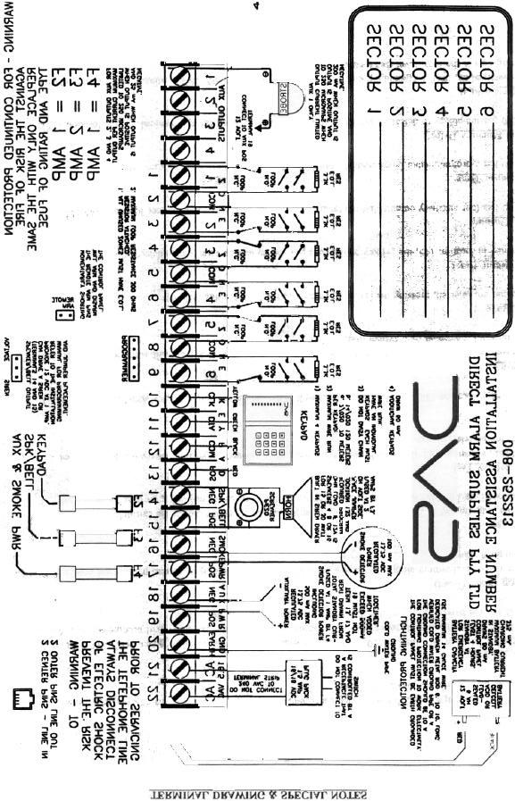
5 TERMINAL DESCRIPTION TERMINAL NO. DESCRIPTION 1 Programmable Auxiliary Output Terminal. Current limited to 250 micro amps positive and 200 ma negative. This Auxiliary output is normally used to connect the negative lead of the strobe. The positive lead of the strobe can be connected to any of the positive terminals. 2-4 Programmable Auxiliary Output Terminals. Current limited to 250 micro amps positive and 20 ma negative. 5 Connect one side of zone 1 loop. The other side of loop to common terminal 6. Open or short causes alarm. 6 Common (-) Terminal 7 Connect one side of zone 2 loop. The other side of loop to common terminal 6. Open or short causes alarm See Terminal Drawing and repeat the above sequence for zones ,18,19,20 Connect code pad wires as follows; yellow to terminal 17, green to terminal 18, black to terminal 19, red to terminal metres maximum run with 7/020 cable, 120 metres maximum run with 14/020 cable. Home run cable to each code pad. 21(-)& 22(+) 23(-)& 24(+) 25(-)& 26(+) Siren driver output to speaker(s), (speaker rating should be 15 watt at 8 or 16 ohm, or 30/40 watt at 4, 8, or 16 ohms). If siren driver disable is selected in location 132, output becomes voltage output, 12VDC, 1 Amp maximum load. Smoke detector power 12VDC, 100 ma maximum (For those jurisdictions which allow the Priority zone to be used with smoke detectors.) Auxiliary Power regulated 12VDC 500 ma maximum. 27 Earth Ground, connect to a cold water pipe or 6 to 10 foot driven rod. 28 & 29 AC input, connect a 16.5V 1.5 Amp Plug Pack. Battery leads Standby battery leads, black (-) and red (+) connect to a 12VDC lead acid rechargeable battery. Do not connect to a dry cell battery. FUSE DESCRIPTION FUSE NO. F1 1 AMP / Code pad DESCRIPTION F2 2 AMP / Siren Driver F3 1 AMP / Aux Power & Smoke Detector Power 5
6 PROGRAMMING The DL100 can be placed into the "Program" mode by use of the new FS4610 Smart Programmer, or the original FS4597 programmer, or for Code Pad programming, by utilising the FS4534 LCD Code Pad (the preferred method) or the FS4623 LED Code Pad. These methods are described below. Using a Programmer The FS4610 Smart Programmer has been designed to make programming of the DL100 simpler as well as more efficient for users. The FS4610 programmer features up to 4 resident standard programs to allow for separate system standardisation. Plug the optional model FS4610 programmer into the 4-pin male outlet marked "program" on the DL100 P.C. Board. Using The LCD Code Pad The most straightforward method of Code Pad programming is to utilise the FS4534 LCD Code Pad in the programming mode. To access the programming mode enter [C] [0] [0], followed by the four digit "Go To Program" access code which is factory default [9] [0] [5] [0] (this code can be reprogrammed), and follow the Code Pad prompts. Using The LED Code Pad The DL100 can also be programmed by the standard binary method of Code Pad programming described below. When the FS4623 LED Code Pad is used for programming, enter the factory default four digit "Go To Program" access code of [9] [7] [1] [3]. NOTE: The DL100 must be disarmed to gain access to programming with this code. After entry of this code, the DL100 will be in the "Program" mode, and the yellow LED's will display the data in location 000. The data is displayed using a Binary system. With this system the yellow zone 1 LED equals "1" when illuminated. The zone 2 LED equals "2" when illuminated. The zone 3 LED equals "4" when illuminated. The zone 4 LED equals "8" when illuminated. Thus if the data in location 000 is "9", the LED for zone 1 (=1) and zone 4 (=8) would be illuminated. By adding the two values together, (1+8=9) you would determine that the data in location 000 is "9". If the data in location 000 is "6", the LEDs for zone 2 (=2) and zone 3 (=4) would be added (2+4=6) indicating the data in that location to be "6". If no LED's are illuminated, the location contains a "0". To advance from location 000 through 255, press the [#] key. To go to a specific location, press the location number followed by the [#] key. The yellow LED's will then display the data in that location. Data is changed by entering a number between 0 and 15, followed by [*] (* = data enter). Review the examples in figure 1 on the following page. Important Function Codes [9]-[5]-[0]-[#] When in the program mode, this function code can be used to write original factory default codes into the DL100. [9]-[3]-[0]-[#] This function code is used to exit the programming mode after it was accessed via the Code Pad.!!! IMPORTANT!!! Before programming the DL100 for the first time, enter the "Go To Program Code" [9][7][1][3] from the Code Pad, followed by the factory default function code [9][5][0][#]. The panel defaults will now match this installation manual and you may begin programming the control panel. When using an optional plug-in programmer which automatically enters the programming mode, the only entry necessary is [9][5][0][#] to load factory defaults. 6
7 7
8 PROGRAMMING THE COMMUNICATOR THIS PAGE DESCRIBES ALL THE LOCATIONS THAT MUST BE PROGRAMMED IN ORDER FOR THE DAS DL100 TO FUNCTION AND REPORT TO A CENTRAL STATION. OTHER OPTIONS MAY BE SELECTED BY FOLLOWING THE ADDITIONAL PROGRAMMING INSTRUCTIONS. LOCATIONS : PROGRAMMING THE PRIMARY TELEPHONE NUMBER The primary telephone number is programmed in successive locations beginning with location 032. Any zero (0) within the telephone number, must be programmed as a "10". A "0" indicates the end of the phone number. Delays of four seconds can be programmed at any point in the phone number by programming a "13" in the appropriate location. If a "*" or "#" are required in your phone number then a "11" = "*" and "12" = "#". If tone dialling is desired, program a "15" in the location where tone dialling should begin. If the entire number should be tone dialling, program a "15" in location 032. Example: Phone number with touch-tone dialling would be entered as [15]][*][#][10][*][#][2][*][#][7][*][#][2][*][#][4][*][#][4][*][#][2][*][#][1][*][#][1][*] [#][0][*][#]. The "15" selects touch-tone dialling, and the "0" ends the phone number. LOCATIONS :PROGRAMMING THE ACCOUNT CODE FOR THE PRIMARY PHONE NUMBER The account code sent when the PRIMARY phone number is dialled is programmed in locations Any zero (0) within the account code must be programmed as a "10", and the communicator will report a zero (0). If the account code is three digits long, use locations 048, 049, and 050. Program a "0" to indicate the end of the account code. Example: Account number of 2090 would be entered as [2][*][#] [10][*][#] [9][*][#] [10][*][#] [0][*][#] (starting at location 48). Account code of 209 for low speed would be entered as [2][*][#] [10][*][#] [9][*][#] [0][*][#] (starting at location 48). LOCATION 052: PROGRAMMING COMMUNICATOR FORMAT FOR THE PRIMARY PHONE NUMBER Location 052 contains the communicator format used to transmit to the receiver connected to the primary phone number. Consult the instructions for your central station receiver to determine which format is compatible. To select Ademco High Speed, program a "4" in location 052. Contact I.D requires a "1" in this location. If you need another format, choose from those listed in the format table located on the following page, and program the data in location 052. If this location contains a "0", the built-in communicator will be disabled, and the DAS DL100 will function as a local only control. LOCATION 053: RESERVED FOR FUTURE USE LOCATIONS : PROGRAMMING THE SECONDARY TELEPHONE NUMBER Locations contain the secondary telephone number. This number allows certain communicator reports to go to another number, or to cause the communicator to dial a second number if the primary number does not respond after the number of attempts programmed into location 134 have been tried unsuccessfully. The same number of attempts are made with the back-up number. Tone dialling and delay instructions are the same as for the primary number. LOCATIONS : RESERVED FOR FUTURE USE 8
9 COMMUNICATOR FORMAT TABLE DATA FORMAT DESCRIPTION 0 LOCAL ONLY COMMUNICATOR IS DISABLED 1 ADEMCO CONTACT ID DTMF FORMAT 2 ADEMCO 4/2 EXPRESS DTMF FORMAT 3 PAGER FORMAT REPORTS IN FORMAT OR DOMESTIC DIALLING 4 ADEMCO HIGH SPEED DTMF FORMAT 5 RADIONICS EXTENDED SLOW 1800Hz TRANSMITTAL 2300Hz HANDSHAKE 20 PPS HEX EXT DOUBLE ROUND 6 CADDX MODEM PROPRIETARY 7 RADIONICS EXTENDED FAST 1800Hz TRANSMITTAL 2300Hz HANDSHAKE 40 PPS HEX EXT DOUBLE ROUND 8 RADIONICS EXTENDED FAST 1800Hz TRANSMITTAL 1400Hz HANDSHAKE 40 PPS HEX EXT DOUBLE ROUND 9 RADIONICS EXT FAST W/PARITY 10 NOT USED 11 ADEMCO/SILENT KNIGHT SLOW 1800Hz TRANSMITTAL 2300Hz HANDSHAKE 40 PPS HEX EXTENDED 1900Hz TRANSMITTAL 1400Hz HANDSHAKE 10 PPS DOUBLE ROUND PARITY 12 SILENT KNIGHT 4+2 FAST 1900Hz TRANSMITTAL 1400Hz HANDSHAKE 20 PPS DOUBLE ROUND PARITY 13 SESCOA/FRANKLIN FAST 1800Hz TRANSMITTAL 2300Hz HANDSHAKE 20 PPS HEX DOUBLE ROUND 14 SIA FSK FORMAT 15 CUSTOM FORMAT SELECT YOU OWN FORMAT FOR NON STANDARD BASE STATIONS. REF:- TO YOUR DAS BRANCH FOR MORE INFORMATION. 9
10 LOCATIONS : PROGRAMMING THE MASTER ARM/DISARM CODE Locations contain master arm/disarm code (user number 1). Location 00 contains the first digit of the code; location 003 contains the fourth digit of the code. THE CODE MUST CONTAIN FOUR (4) DIGITS. The master code can then be used in the run mode to enter arm/disarm codes 1-7 (see page 40, ENTERING AND CHANGING THE MASTER CODE). The factory default code is [1][2][3][4]. LOCATIONS : PROGRAMMING THE ARM/DISARM CODE FOR USERS 2 THRU 6 Locations contain the arm/disarm codes for user numbers 2 thru 6. Location 004 contains the first digit of the code #2, and location 007 contains the fourth digit of code #2. THESE CODES MUST CONTAIN FOUR (4) DIGITS. To disable a code, PROGRAM a "15" as the first digit of the code. These codes can be changed in the RUN mode using the master code (see page 38, ENTERING AND CHANGING AUXILIARY CODES). LOCATIONS : PROGRAMMING THE DURESS CODE OR USER 7 Locations , contain the arm/disarm code for Duress or for user number 7. Duress capability is enabled, by programming a communicator code in locations If locations are left unprogrammed, user number 7 will act as a standard user code. LOCATIONS : PROGRAMMING THE "GO TO PROGRAM" ACCESS CODE Locations , contain the "Go To Program" access code. Location 028 contains the first digit of the code and location 031 contains the fourth digit of the code. THE CODE MUST CONTAIN FOUR (4) DIGITS. With the DAS DL100 disarmed, the "Go To Program" access code can be used to enter the program mode. To disable the "Go To Program" access code, program a "15" in location 028. The factory default setting is [9][7][1][3]. LOCATIONS : SEE PAGE 8 LOCATION 075: PROGRAMMING THE ENTRY DELAY TIME Location 075 contains the number of 10 Second increments in the entry delay. The entry delay can be programmed in 10 second increments from 10 to 150 seconds ("1" = 10 seconds through "15" = 150 seconds). For example, programming a "2" in this location will produce an entry delay of 20 seconds. (Note: A "0" entry is treated as 0 seconds). Programming a "6" in this location will produce an entry delay of 60 seconds. Factory default is 30 seconds. LOCATION 076: PROGRAMMING THE EXIT DELAY TIME Location 076 contains the number of 10 Second increments in the exit delay. The exit delay can be programmed in 10 second increments from 10 to 150 seconds ("1" = 10 seconds through "15" =150 seconds). For example, programming a "2" in this location will produce an exit delay of 20 seconds. (Note: A "0" entry is treated as 0 seconds). Programming a "6" in this location will produce an exit delay of 60 seconds. Factory default is 60 seconds. LOCATION 077: PROGRAMMING THE SIREN SHUTDOWN/RECYCLE TIMEOUT Location 077 contains the number of 2 minute increments in the automatic cutoff time. The automatic cutoff time can be programmed in 2 minute increments from 2 to 30 minutes ("1" = 2 min thru "15" = 30 min). For example, programming a "2" in this location will produce an automatic cutoff time of 4 minutes. Programming a "6" in this location will produce an automatic cutoff time of 12 minutes. 10
11 LOCATIONS : PROGRAMMING THE ZONE TYPES Locations 078 through 085 contain a number identifying the characteristics of each of the 8 zones. Location 078 corresponds to zone 1 and location 085 corresponds to zone 8. Each zone will factory default according to the programming worksheet. To program zone characteristics other than the default values, program a number from "1" to "9" based on the characteristics in the list below. NUMBER ZONE CHARACTERISTICS DESCRIPTION "1" DAY ZONE - A trip on a Day zone will produce an instant alarm when armed and activate the code pad sounder when disarmed. "2" 24 HOUR - A trip on a 24 Hour zone will produce an instant alarm when the DAS DL100 is armed or disarmed. "3" ENTRY/EXIT - A trip will start entry delay. The lack of a trip during exit delay will enable the "Automatic Bypass" or "Instant" mode if so programmed. "4" INTERIOR DELAY - A trip on Interior Delay zone will initiate an entry delay. It will be ignored during exit delay and when disarmed. This zone type is used with the "Automatic Bypass/Instant" mode. "5" HANDOVER - Interior zone that follows delay zones. It can be bypassed before arming, or automatically bypassed in the "Automatic Bypass/Instant" mode if so programmed. "6" INSTANT Produces an instant alarm when tripped in the armed mode, ignored when disarmed. "7" 24 HOUR SILENT - A trip on a 24 hour silent zone will communicate to the central station when the DAS DL100 is armed or disarmed. "8" PRIORITY - A short on a Priority zone type will communicate to the central station when the DAS DL100 is armed or disarmed. Priority zones cannot be bypassed. "9" SECONDARY DELAY - A secondary delay zone works like an interior delay zone but has its own independent delay time (see locations ). NOTE: WHEN PROGRAMMING THE FOLLOWING COMMUNICATOR CODES, A "10" MUST BE PROGRAMMED IN ORDER TO REPORT A ZERO (0). LOCATION : PROGRAMMING THE DAS DL100 FOR DURESS CODE CAPABILITY The DAS DL100 has the ability to report a duress code when the system is armed or disarmed with user code number 7 and a duress communicator code is programmed in locations Location 086 contains the standard digit, and location 087 contains the extended digit. When using Ademco High Speed, program a one (1) in the first location to enable this report, a " " Duress is reported. When contact I.D is selected, program the extended or the second location with the required event code from appendix 1 to enable this report event. Programming a "10" in location 87 will report an event "121 - Duress". The Open/Close report will accompany the Duress report complete with the user number to indicate that an Open or Close was preformed under Duress. No restore code is reported for this event. If both locations are "0", the duress capability is disabled and user code number 7 can only be used as a standard arm/disarm code. 11
12 LOCATION : PROGRAMMING FOR AUXILIARY 1, [1] & [3] DOUBLE KEYPRESS The DAS DL100 has the ability to report an Auxiliary 1 code and activate the Priority siren each time the [1] and [3] keys are pressed simultaneously on the code pad. The desired reporting code is programmed in locations Location 088 contains the standard digit, and location 089 contains the extended digit. When using Ademco High Speed, program a one (1) in the first location to enable this report, a " " Duress is reported. When contact I.D is selected, program the extended or the second location with the required event code from appendix 1 to enable this report event. Programming a "1" in location 89 will report an event "110 - Fire". If activated, the siren can be silenced by entering any arm/disarm code. No restore code is reported for this event. If both locations are "0", the Auxiliary 1 double keypress is disabled. LOCATION : PROGRAMMING FOR AUXILIARY 2, [4] & [6] DOUBLE KEYPRESS The DAS DL100 has the ability to report an Auxiliary 2 code and activate the pulsing buzzer each time the [4] and [6] keys are pressed simultaneously on the code pad. The desired Auxiliary 2 code is programmed in locations Location 090 contains the standard digit, and location 091 contains the extended digit. When using Ademco High Speed, program a one (1) in the first location to enable this report, a " " Duress is reported. When contact I.D is selected, program the extended or the second location with the required event code from appendix 1 to enable this report event. Programming a "11" in location 91 will report an event "100 - Medical". If activated, the code pad sounder can be silenced by entering any Arm/Disarm code. No restore code is reported for this event. If both locations are "0", the Auxiliary 2 double keypress is disabled. LOCATION : PROGRAMMING FOR Code pad PANIC, [*] & [#] DOUBLE KEYPRESS The DAS DL100 has the ability to report a Code pad panic code and activate the Burg siren each time the [*] and [#] keys are pressed simultaneously on the code pad. The desired Code pad panic code is programmed in locations Location 092 contains the standard digit, and location 093 contains the extended digit. When using Ademco High Speed, program a one (1) in the first location to enable this report, a " " Duress is reported. When contact I.D is selected, program the extended or the second location with the required event code from appendix 1 to enable this report event. Programming a "2" in location 93 will report an event "120 - Code Pad Panic". If activated, the siren can be silenced by entering any Arm/Disarm code. No restore code is reported for this event. If both locations are "0", the Code pad panic double keypress is disabled. LOCATION : PROGRAMMING THE CODE PAD TAMPER FEATURE The DAS DL100 has an optional tamper feature that, when enabled, will lock out the code pads for 1 minute if 30 random keypresses are made without producing a valid code. The desired tamper code should be programmed in locations If the control is not programmed for local only, the tamper will be communicated. Location 094 contains the standard digit, and location 095 contains the extended digit. When using Ademco High Speed, program a one (1) in the first location to enable this report,a zone 8 alarm " " will be reported. When contact I.D is selected, program a one (1) in the extended or the second location to enable this report, an event "137 - Code Pad Tamper" will be reported. No restore code is reported for this event. If both locations are "0", the tamper feature will not be enabled or reported. LOCATION : PROGRAMMING TO REPORT DOWNLOADING COMPLETE Locations contain the communicator report, sent each time a download session has been completed. The report will come in, after a disconnection has been made from a downloading session. Location 096 contains the standard communicator code, and location 097 contains the extended communicator code. When using Ademco High Speed, program a one (1) in the first location to enable this report, a " " is reported. When contact I.D is selected, program a one (1) in the extended or the second location to enable this report, an event "412 - Download Complete" will be reported. If locations are "0", this report is disabled. LOCATION : PROGRAMMING FOR AUTOTEST REPORTS The DAS DL100 has the ability to send autotest reports at intervals from 1 to 15 days. Locations contain the communicator codes sent for autotest. Location 098 contains the standard communicator code, and location 099 contains the extended communicator code. When using Ademco High Speed, program a one (1) in the first location to enable this report, a " " is reported. When contact I.D is selected, program a one (1) in the extended or the second location to enable this report, an event "602 - Autotest" will be reported. If locations are "0", autotest is disabled. (NOTE: WHEN USING AUTOTEST, LOCATIONS MUST BE PROGRAMMED.) 12
13 LOCATION : RESERVED FOR FUTURE USE LOCATION 102: PROGRAMMING TO REPORT CLOSING The DAS DL100 has the ability to report a closing code each time the control is armed. Program a "1" in this location to enable this report. When using a one button "Quick Arm" code and when using the remote arming input, the user number one (1) is reported. The closing report will not be initiated until the end of the exit delay. When Ademco high speed is selected a "U " event is reported. When Contact I.D. is selected an event "401 - Open/Close" is reported. If this location contains a "0", closing will not be reported. LOCATION 103: PROGRAMMING TO REPORT OPENINGS The DAS DL100 has the ability to report an opening code each time the control is disarmed. Program a "1" in this location to enable this report. When using the remote arming input, the user number one (1) is reported. When Ademco high speed is selected a "U " event is reported. When Contact I.D. is selected an event "401 - Open/Close" is reported. If this location contains "0", openings will not be reported. LOCATION : PROGRAMMING THE COMMUNICATOR CODE FOR ZONE 1 Locations contain the communicator code to be reported each time zone 1 creates an alarm. Location 104 contains the standard digit, and location 105 contains the extended digit. When using Ademco High Speed, program a one (1) in the first location to enable this report, a " " is reported. When contact I.D is selected, program the extended or the second location with the required event code from appendix 1 to enable this report event, programming a three (3) in the extended or the second location, will select an event "130 - Burglary" to be reported. The data in the standard location or first location must be left at default or changed to the zone number that is to be reported. If locations are "0", this report is disabled. LOCATION : PROGRAMMING THE COMMUNICATOR CODE FOR ZONE 2 Locations contain the communicator code to be reported each time zone 2 creates an alarm. Location 106 contains the standard digit, and location 107 contains the extended digit. When using Ademco High Speed, program a one (2) in the first location to enable this report, a " " is reported. When contact I.D is selected, program the extended or the second location with the required event code from appendix 1 to enable this report event, programming a three (3) in the extended or the second location, will select an event "130 - Burglary" to be reported. The data in the standard location or first location must be left at default or changed to the zone number that is to be reported. If locations are "0", this report is disabled. LOCATION : PROGRAMMING THE COMMUNICATOR CODE FOR ZONE 3 Locations contain the communicator code to be reported each time zone 3 creates an alarm. Location 108 contains the standard digit, and location 109 contains the extended digit. When using Ademco High Speed, program a one (3) in the first location to enable this report, a " " is reported. When contact I.D is selected, program the extended or the second location with the required event code from appendix 1 to enable this report event, programming a three (3) in the extended or the second location, will select an event "130 - Burglary" to be reported. The data in the standard location or first location must be left at default or changed to the zone number that is to be reported. If locations are "0", this report is disabled. LOCATION : PROGRAMMING THE COMMUNICATOR CODE FOR ZONE 4 Locations contain the communicator code to be reported each time zone 4 creates an alarm. Location 110 contains the standard digit, and location 111 contains the extended digit. When using Ademco High Speed, program a one (4) in the first location to enable this report, a " " is reported.. When contact I.D is selected, program the extended or the second location with the required event code from appendix 1 to enable this report event, programming a three (3) in the extended or the second location, will select an event "130 - Burglary" to be reported. The data in the standard location or first location must be left at default or changed to the zone number that is to be reported. If locations are "0", this report is disabled 13
14 LOCATION : PROGRAMMING THE COMMUNICATOR CODE FOR ZONE 5 Locations contain the communicator code to be reported each time zone 5 creates an alarm. Location 112 contains the standard digit, and location 113 contains the extended digit. When using Ademco High Speed, program a one (5) in the first location to enable this report, a " " is reported. When contact I.D is selected, program the extended or the second location with the required event code from appendix 1 to enable this report event, programming a three (3) in the extended or the second location, will select an event "130 - Burglary" to be reported. The data in the standard location or first location must be left at default or changed to the zone number that is to be reported. If locations are "0", this report is disabled. LOCATION : PROGRAMMING THE COMMUNICATOR CODE FOR ZONE 6 Locations contain the communicator code to be reported each time zone 6 creates an alarm. Location 114 contains the standard digit, and location 115 contains the extended digit. When using Ademco High Speed, program a one (6) in the first location to enable this report, a " " is reported. When contact I.D is selected, program the extended or the second location with the required event code from appendix 1 to enable this report event, programming a three (3) in the extended or the second location, will select an event "130 - Burglary" to be reported. The data in the standard location or first location must be left at default or changed to the zone number that is to be reported. If locations are "0", this report is disabled. LOCATION : RESERVED FOR FUTURE USE LOCATION : PROGRAMMING TO REPORT AC POWER LOSS The DAS DL100 has the ability to report an AC power failure code when AC power is lost. This report can be immediate, or delayed depending on the information programmed in location 150 (AC POWER LOSS DELAY). The desired AC failure mode should be programmed in locations Location 120 contains the standard digit, and location 121 contains the extended digit. When using Ademco High Speed, program a one (1) in the first location to enable this report, a " " is reported. When contact I.D is selected, program a one (1) in the extended or the second location to enable this report, an event "301 - A.C. Loss" will be reported. A.C Loss will only report when the A.C power has been disconnected for period equal to the minutes programmed in location 150. If both locations are "0", AC power failures will not be reported. LOCATION : PROGRAMMING TO REPORT LOW BATTERY The DAS DL100 has the ability to report a low battery code when AC power has been lost and the battery has discharged down to 10.3 volts. The desired low battery code is programmed in locations Location 122 contains the standard digit, and, location 123 contains the extended digit. When using Ademco High Speed, program a one (1) in the first location to enable this report, a " " is reported. When contact I.D is selected, program a one (1) in the extended or the second location to enable this report, an event "302 - Low Battery" will be reported. Low battery will only report when the A.C power is disconnected and the battery voltage drops below 10.2v D.C.. If both locations are "0", low battery will not be reported. LOCATION 124: PROGRAMMING FOR PRIORITY ZONE TROUBLE REPORTING The DAS DL100 has the ability to report a trouble code each time a Priority zone opens. The desired trouble code is programmed in location 124. When using Ademco High Speed, program a one (1) in this location to enable this report. A one (1) will be displayed for the channel corresponding to the zone in Trouble alarm. E.G, " " will be reported for zone two (2). When contact I.D is selected, program a one (1) in this location to enable this report, an event "380 - Zone Trouble" will be reported. If this location contains a "0", the Priority Trouble will not be reported. LOCATION 125: PROGRAMMING FOR ISOLATE REPORTING The DAS DL100 has the ability to report an Isolate on zones 1-6. The desired Isolate code is programmed in location 125. When using Ademco High Speed, program a one (1) in this location to enable this report. A one (1) will be displayed for the channel corresponding to the zone that is Isolated. E.G, " " will be reported for zone two (2). When contact I.D is selected, program a one (1) in this location to enable this report, an event "380 - Zone Isolate" will be reported. If this location contains a "0", zone Isolate will not be reported. 14
15 LOCATION 126: PROGRAMMING THE COMMUNICATOR CODE FOR RESTORAL Location 126 contains the communicator code that will be sent for restoral of a zones and or system report events. When using Ademco High Speed, program a one (1) in this location to enable this report. When contact I.D is selected, program a one (1) in this location to enable this report. If this location contains a "0", no restorals will be reported. LOCATION 127: PROGRAMMING THE COMMUNICATOR CODE FOR CANCEL (EXCEPTION OPENING) Location 127 contains the communicator code that will be sent for cancel. The cancel code programmed in this location will be sent if an arm/disarm code is entered after a trip on zones 1 through 6 has been reported (excluding 24 hour zones). After a cancel has been reported, no loop restorals will be transmitted on non-24 Hour zones. When using Ademco High Speed, program a one (1) in this location to enable this report, the opening event will be reported with the user code number used. When contact I.D is selected, program a one (1) in this location to enable this report, the opening event will be reported with the user code number used. This feature can not be enable when Open/Close reporting is also enabled. If this location contains a "0", cancel is disabled. LOCATION 128: PROGRAMMING THE COMMUNICATOR TO ABORT Location 128 contains the number of 3 second increments in the communicator abort feature which is programmable from 3 to 45 seconds ("1" = 3 seconds through "15" = 45 seconds). For example, programming a "2" in this location will produce an abort time of 6 seconds. The DL-100 will abort the alarm report on any non-24 hour zone, if an arm/disarm code is entered within the abort time. If this location contains a "0", the DL-100 will not abort any reports. LOCATION 129: PROGRAMMING FOR SILENT PANIC/HOLD-UP Location 129 is used to silence the audible output for a panic/hold -up alarm. Programming a "1" in this location will silence the audible output during a panic/hold-up alarm. If this location contains a "0", the DAS DL100 will have an audible panic/hold-up output. LOCATION 130: LIMITED SIREN AND/OR COMMUNICATOR OUTPUTS Location 130 is used to limit the sirens or the communicator, or both, to one output per zone during a single arming cycle. The following table will indicate the value to be programmed in location 130 to give the DL100 the desired characteristics. Factory default is "1", once per zone for the siren, and unlimited reports for the communicator. VALUE DESCRIPTION 0 SIRENS AND COMMUNICATOR NOT LIMITED 1 SIREN ONCE PER ZONE, COMMUNICATOR NOT LIMITED 2 COMMUNICATOR ONE REPORT PER ZONE, SIREN NOT LIMITED 3 SIREN AND COMMUNICATOR LIMITED TO ONCE PER ZONE LOCATION 131: AUTOMATIC BYPASS / INSTANT ARMING - PARTIAL MODE SECURITY FEATURE Location 131 is used to enable automatic "Instant Arming" or "Partial Arm" (Entry-Guard).. Programming a "1" in this location will cause the control to automatically enter the "Instant" mode and bypass interior follower zones if a fault is not detected on an entry/exit zone during the exit delay. Programming a "3" in this location (Automatic Bypass), will cause the interior follower zones to become bypassed if a fault is not detected on an entry/exit zone, yet will not change the status of the entry/exit zone. Programming a "8" will enable the Partial Arm security feature, which requires a four digit code to disarm the Partial Arm mode. If this location contains a "0", these features are disabled. DATA CHARACTERISTIC 1 ENABLE AUTO "INSTANT MODE" 3 ENABLE AUTO "HANDOVER ISOLATE" WITH ENTRY ZONE DELAY 8 ENABLE "PARTIAL MODE" (ENTRY-GUARD) SECURITY FEATURE 15
16 LOCATION 132: BUILT-IN SIREN DRIVER / 1 AMP VOLTAGE OUTPUT The built-in siren driver has a steady sound (for Priority zone type), and a yelp sound (for Burglary and Panic). Factory default is "0", enabling this feature. If the built-in siren driver is NOT to be used, take the following procedure. First, remove the jumper on the PC board. Next, program a "1" in location 132. Finally, replace the jumper in the voltage position. Terminals 21 & 22 will now output 1 Amp at 12VDC. The Fire, Panic, and Burglary options for the Auxiliary Outputs can be programmed for momentary, or to follow the siren. Programming a "2" in location 132 will cause the Fire, Panic, or Burglary auxiliary outputs to activate for 10 seconds each time a Fire, Panic, or Burglary activates. Programming a "0" in location 132 will cause the Burg and Panic outputs to activate when the yelping siren is on and the Fire Auxiliary output to activate when the steady siren is on. LOCATION 133: L.E.D. EXTINGUISH FEATURE Code pad LEDs (with the exception of the A.C. LED) will be extinguished after 60 seconds of code pad inactivity, if a "1" is programmed in location 133. The LEDs will become illuminated immediately upon a keypress or alarm condition. LOCATION 134: ENTERING THE NUMBER OF DIAL ATTEMPTS Location 134 is used to enter the number of dial attempts (1 to 15 attempts) the communicator will try for the appropriate phone number(s) before ending the notification process. If this location contains an "8", the communicator will make 8 attempts to the first number, and then eight attempts to a second number, if a second number is programmed as backup. LOCATION 135: POWER UP CONDITION If a "1" is programmed in location 135, the DAS DL100 will power-up disarmed if there is a total power shutdown and battery failure. If a "2" is programmed in this location, it will power up armed. If this location contains a "0", the DAS DL100 will maintain the condition it was in at power down. A watchdog circuit reset will cause the DAS DL100 to reset to the selected condition. LOCATION 136: POWER UP DELAY If a one "1" is programmed in location 136, the DAS DL100 will not delay 60 seconds before accepting open or short inputs from any zone. If a "0" is programmed, sensors on all zones are allowed 60 seconds to stabilise at power-up, or after exiting the program mode. After 60 seconds, the DL-100 will once again accept loop opens or shorts as an alarm condition. This 60 Second period will also be initiated after a watchdog circuit reset condition. LOCATION 137:IMMEDIATE RESTORE BY ZONE If a "1" is programmed in location 137, restoral signals will follow the restore condition and report restores immediately after the condition has unfaulted. A non-extended format will not send a restore message until all zones and trouble conditions have restored. If this location contains a "0", the restore signal or signals will be reported only after siren timeout. LOCATION 138: NO ARMING WITH A ZONE BYPASSED If a "1" is programmed in location 138, the DAS DL100 will not arm with any zone bypassed. If programmed with a "0", 6 of the 6 burglary zones can be bypassed, and the DAS DL100 can still be armed. 16
17 LOCATION 139: PROGRAMMING THE QUICK ARM DIGIT The DAS DL100 can be programmed to "Quick Arm" with digit [3], by programming a one (1) in location 139. A "0 " in this location will disable this feature. If the "Quick Arm" digit is the same as the first digit of the Master code (user 1), the "Door Chime Annunciation" feature will not function. LOCATION : RESERVED FOR FUTURE USE LOCATION 142: SIREN/BELL TEST FEATURE The siren/bell can be programmed to activate upon different conditions. Using the chart below, add the values of the desired condition(s) and program the sum of those values in location 142. When the siren/bell is activated by pressing the [1] and [7] keys simultaneously,, the communicator will not report a message, and the siren/bell can be silenced by entering an arm/disarm code. VALUE DESCRIPTION 1 Activation by pressing [1] and [7] keys simultaneously 2 Momentary activation at arming 4 Momentary at end of exit delay 8 Momentary at kiss off ringback LOCATION 143: SMOKE POWER RESET AND/OR FIRE ALARM VERIFICATION Programming a "1" in location 143 will cause the DL100 (when in the disarmed state) to interrupt the smoke detector power each time the [#] button is pressed. If this location contains a "0", the smoke detector power will reset only after the [#] button is pressed when the corresponding LED(s) for zones designated as "Priority" are on steady for alarm or blinking for trouble. Programming a "2" in this location will enable the "Fire Alarm Verification" feature. When the "Fire Alarm Verification" feature is enabled, a smoke detector will be powered down and reset automatically after the first trip, waiting for a second trip within a 30 minute time frame (thus verifying a fire alarm condition) before creating an alarm and communicating a message. LOCATION 144: RESERVED FOR FUTURE USE LOCATION : PROGRAMMING THE AUXILIARY OUTPUTS The DL100 has 4 auxiliary outputs located on terminals 1 thru 4 on the control PC board. These outputs can be activated by 10 different conditions. To utilise the outputs, program a number from "0" to "9" in locations 145 (output 1) to location 148 (output 4) according to the desired characteristics listed on the following page. Output 1 is terminal 1 and output 4 is terminal 4. 17
18 AUXILIARY OUTPUT TABLE PROGRAM DIGIT ACTIVATION ON NOTES "0" BURGLARY ALARM MOMENTARY OUTPUT "1" FIRE ALARM MOMENTARY OUTPUT "2" PANIC ALARM/DURESS MOMENTARY OUTPUT "3" ARMED STATE LATCHED OUTPUT "4" ARMED WITH BYPASS LATCHED OUTPUT "5" AC POWER LATCHED OUTPUT "6" LOW BATTERY LATCHED OUTPUT "7" LINE SEIZURE MOMENTARY OUTPUT "8" TAMPER ALARM LATCHED OUTPUT "9" AUTOTEST MOMENTARY OUTPUT "10" NOT USED NOT USED "11" STROBE LATCHED OUTPUT "12" ENTRY LATCHED OUTPUT "13" EXIT LATCHED OUTPUT "14" STATUS LED LATCHED OUTPUT "15" NOT USED NOT USED LOCATIONS 149: INVERTING THE AUXILIARY OUTPUTS The auxiliary outputs of the DL100 are normally POSITIVE (+) going NEGATIVE (-). They can be changed to a normally NEGATIVE (-) going POSITIVE (+) by programming the appropriate number in location149. Auxiliary output 1 has a value of "1", Auxiliary output 2 has a value of "2", Auxiliary output 3 has a value of "4", and Auxiliary output 4 has a value of "8". The values for the outputs that you wish to change to NEGATIVE going POSITIVE must be added together and the total programmed in location 149. For example, if you wished to make outputs 2 ="2" and 3 ="4" NEGATIVE going POSITIVE, you would program "6" (2+4=6) in location 149. {NOTE: CURRENT LIMITED TO 250 MICRO AMPS POSITIVE AND 20 ma NEGATIVE). VALUE OUTPUT INVERSION VALUE OUTPUT INVERSION 0 NO AUX INVERTED 8 INVERT AUX 4 OUTPUT 1 INVERT AUX 1 OUTPUT 9 INVERT AUX 1 & 4 OUTPUT 2 INVERT AUX 2 OUTPUT 10 INVERT AUX 2 & 4 OUTPUT 3 INVERT AUX 1 & 2 OUTPUT 11 INVERT AUX 1, 2 & 4 OUTPUT 4 INVERT AUX 3 OUTPUT 12 INVERT AUX 3 & 4 OUTPUT 5 INVERT AUX 1 & 3 OUTPUT 13 INVERT AUX 1, 3 & 4 OUTPUT 6 INVERT AUX 2 & 3 OUTPUT 14 INVERT AUX 2, 3 & 4 OUTPUT 7 INVERT AUX 1, 2 & 3 OUTPUT 15 INVERT AUX 1, 2, 3 & 4 OUTPUT 18
19 LOCATION 150: AC POWER LOSS DELAY FEATURE Location 150 contains the number of one minute delays (one to seven minutes) the communicator will wait before reporting an AC power failure. A "1" programmed in this location will create a one minute delay, and a "7" will create a seven minute delay. If a "0" is programmed in this location, AC power failures will be reported immediately if AC power loss reporting is enabled in locations LOCATION 151: PROGRAMMING THE NUMBER OF RINGS TO ANSWER DOWNLOAD CALL Location 151 contains the number of rings the DL100 must detect before answering the telephone when initiating a download. If a number from "1" to "15" is programmed in this location, the control will answer after THAT number of rings has been detected. If a "0" is programmed in this location, the DL100 will not answer the download call. (SEE LOCATION 212: ANSWERING MACHINE DEFEAT) LOCATION 152: PROGRAMMING THE NUMBER OF DAYS LEFT UNTIL AUTOTEST REPORT Location 152 contains the number of days left until the next autotest report. If this location contains a "0", an autotest signal will be reported the first time the current time equals the autotest time programmed in locations Locations must be programmed to enable autotest reporting. LOCATION 153: PROGRAMMING THE CLOCK, CURRENT MONTH Location 153 contains the current month. The month must be programmed using a number from "1" to "12". This location must be programmed when using the maintenance code feature (see location 167). LOCATION 154: PROGRAMMING THE CLOCK, CURRENT YEAR - TENS DIGIT Location 154 contains the current year - tens digit. If the current year is 1994, this location should contain a 9, which is the tens digit of the current year. LOCATION 155: PROGRAMMING THE CLOCK, CURRENT YEAR - ONES DIGIT Location 155 contains the current year - ones digit. If the current year is 1994, this location should contain a "4", which is the ones digit of the current year. If the current year is 1995, this location should contain a "5", which is the ones digit of the current year. LOCATION 156: PROGRAMMING THE CLOCK, CURRENT DAY OF THE MONTH - TENS DIGIT Location 156 contains the current day of the month - tens digit. If the current day of the month is the 5th (05), this location should contain a "0", which is the current day of the month - tens digit. If the current day of the month is the 26th, this location should contain a "2". LOCATION 157: PROGRAMMING THE CLOCK, CURRENT DAY OF THE MONTH - ONES DIGIT Location 157 contains the current day of the month - ones digit. If the current day of the month is the 5th (05), this location should contain a "5", which is the current day of the month - ones digit. If the current day of the month is the 26th, this location should contain a "6". LOCATION 158: PROGRAMMING THE CLOCK, CURRENT HOUR - TENS DIGIT Location 158 contains the current hour - tens digit. The time is entered in 24 hour time. If the current time is 5:25 PM, the 24 hour time is 17:25, so this location should contain a "1", which is the current hour - tens digit. If the current time is 9:36 AM, the 24 hour time is 09:36, so this location should contain a "0". 19
20 LOCATION 159: PROGRAMMING THE CLOCK, CURRENT HOUR - ONES DIGIT Location 159 contains the current hour - ones digit. The time is entered in 24 hour time. If the current time is 5:25 PM, the 24 hour time is 17:25, so this location should contain a "7", which is the current hour - ones digit. If the current time is 9:36 AM, the 24 hour time is 09:36, and this location should contain a "9". LOCATION 160: PROGRAMMING THE CLOCK, CURRENT MINUTES - TENS DIGIT Location 160 contains the current minutes - tens digit. The time is entered in 24 hour time. If the current time is 5:25 PM, the 24 hour time is 17:25, so location 160 should contain a "2", which is the current minutes - tens digit. If the current time is 9:36 AM, the 24 hour time is 09:36, and this location should contain a "3". LOCATION 161: PROGRAMMING THE CLOCK, CURRENT MINUTES - ONES DIGIT Location 161 contains the current minutes - ones digit. The time is entered in 24 hour time. If the current time is 5:25 PM, the 24 hour time is 17:25, so this location should contain a "5", which is the current minutes - ones digit. If the current time is 9:36 AM, the 24 hour time is 09:36, and this location should contain a "6". LOCATION 162: PROGRAMMING THE AUTOTEST TIME, HOUR - TENS DIGIT Location 162 contains the tens digit of the hour that the autotest report is initiated. The time is entered in 24 hour time. If the desired autotest time is 5:25 PM, the 24 hour time is 17:25, so this location should contain a "1", which is the tens digit of the desired hour for autotest. If the desired autotest time is 9:36 AM, the 24 hour time is 09:36, and this location should contain a "0". LOCATION 163: PROGRAMMING THE AUTOTEST TIME, HOUR - ONES DIGIT Location 163 contains the ones digit of the hour that the autotest report is desired. The time is entered in 24 hour time. If the desired autotest time is 5:25 PM, the 24 hour time is 17:25, so this location should contain a "7", which is the ones digit of the hour for autotest. If the desired autotest time is 9:36 AM, the 24 hour time is 09:36, and this location should contain a "9". LOCATION 164: PROGRAMMING THE AUTOTEST TIME, MINUTES - TENS DIGIT Location 164 contains the tens digit, of the minutes after the hour that the autotest is desired. The time is entered in 24 hour time. If the desired autotest time is 5:25 PM, the 24 hour time is 17:25, so this location should contain a "2", which is the tens digit of the minutes for autotest time. If the desired autotest time is 9:36 AM, the 24 hour time is 09:36, this location should contain a "3". LOCATION 165: PROGRAMMING THE AUTOTEST TIME, MINUTES - ONES DIGIT Location 165 contains the ones digit, of the minutes after the hour that the autotest is desired. The time is entered in 24 hour time. If the desired autotest time is 5:25 PM, the 24 hour time is 17:25, so this location should contain a "5", which is the ones digit of the minutes for autotest time. If the desired autotest time is 9:36 AM, the 24 hour time is 09:36, and this location should contain a "6". LOCATION 166: PROGRAMMING THE AUTOTEST TIME REPORTING INTERVALS Location 166 contains the number of days between automatic test reports. If a report is desired every 7 days, this location should contain a "7". Valid entries are "1" to "15" days. LOCATION : RESERVED FOR FUTURE USE LOCATION 178: PROGRAMMING THE SECONDARY ENTRY DELAY (ZONE TYPE 9) Location 178 contains the number of 10 second increments in the exit delay. The exit delay can be programmed in 10 second increments from 10 to 150 seconds ("1" = 10 seconds through "15" =150 seconds). For example, programming a "2" in this location will produce an exit delay of 20 seconds. (Note: A "0" entry is treated as 0 seconds). Programming a "6" in this location will produce an exit delay of 60 seconds. Factory default is 60 seconds. 20
RANGER 7600 DOWNLOADABLE CONTROL COMMUNICATOR INSTALLATION MANUAL
 RANGER 7600 DOWNLOADABLE CONTROL COMMUNICATOR INSTALLATION MANUAL TABLE OF CONTENTS 1. TABLE OF CONTENTS... P.1 2. GENERAL DESCRIPTION... P.2... 3. STANDARD AND OPTIONAL PARTS LIST... P.2... 4. FEATURE
RANGER 8600 DOWNLOADABLE CONTROL COMMUNICATOR INSTALLATION MANUAL
 RANGER 8600 DOWNLOADABLE CONTROL COMMUNICATOR INSTALLATION MANUAL TABLE OF CONTENTS GENERAL DESCRIPTION... 2 STANDARD AND OPTIONAL PARTS LIST... 2 PARTS DIAGRAM... 3 TERMINAL DRAWING AND SPECIAL NOTES...
DL150 DOWNLOADABLE CONTROL COMMUNICATOR INSTALLATION MANUAL
 DL150 DOWNLOADABLE CONTROL COMMUNICATOR INSTALLATION MANUAL TABLE OF CONTENTS 1. GENERAL DESCRIPTION... 2 2. STANDARD AND OPTIONAL PARTS LIST... 2 3. FEATURE DEFINITIONS... 3 4. TERMINAL DRAWING AND SPECIAL
RANGER 8980E DOWNLOADABLE CONTROL COMMUNICATOR INSTALLATION MANUAL
 RANGER 8980E DOWNLOADABLE CONTROL COMMUNICATOR INSTALLATION MANUAL TABLE OF CONTENTS GENERAL DESCRIPTION...2 STANDARD AND OPTIONAL PARTS LIST...2 FEATURE DEFINITIONS...3 TERMINAL DRAWING AND SPECIAL NOTES...4
TABLE OF CONTENTS. General Description Standard and Optional Parts List Feature Definitions Comments about the 8600E...
 5$1*(5( DOWNLOADABLE CONTROL COMMUNICATOR INSTALLATION MANUAL TABLE OF CONTENTS General Description... 2 Standard and Optional Parts List... 2 Feature Definitions... 3 Comments about the 8600E... 4 Terminal
DL-250 DOWNLOADABLE CONTROL COMMUNICATOR INSTALLATION MANUAL
 DL-250 DOWNLOADABLE CONTROL COMMUNICATOR INSTALLATION MANUAL TABLE OF CONTENTS 1. GENERAL DESCRIPTION...P.2 2. STANDARD AND OPTIONAL PARTS LIST...P.2 3. FEATURE DEFINITIONS...P.3 4. TERMINAL DRAWING AND
Control/Communicator Installation Manual
 DAS NETWORX NX-12 Control/Communicator Installation Manual General Description...2 Ordering Information...2 Option Definitions...3 Programming the LED Code Pads...5 Programming the NX-12...9 Types of Programming
NetworX Series NX-6 CONTROL PANEL. Installation and Startup
 NetworX Series NX-6 CONTROL PANEL Installation and Startup 25 GE Security All rights reserved. These instructions do not purport to cover all details or variations in equipment nor to provide every possible
Fire Burglary Instruments Inc. XL-2G Gold Control/Communicator Installation Training Seminar Rev. 5/96
 Fire Burglary Instruments Inc. XL-2G Gold Control/Communicator Installation Training Seminar Rev. 5/96 XL-2G Gold Product Overview 7 Zones (6 programmable + panic or keyswitch zone) Fast Loop Response
SECURITY SYSTEM NOTES SPECIAL CODES ENTRY / EXIT DELAY TIMES ARM / DISARM CODES ZONE DESCRIPTIONS
 SECURITY SYSTEM NOTES Installing/Service Company For Service Call SPECIAL CODES "Chime" Digit 1 "Partial Arm" Digit 2 "Quick Arm" Digit 3 ENTRY / EXIT DELAY TIMES Exit Delay Time Entry Delay Time Secondary
NetworX Series NX-4V2 Control Panel Installation and Startup
 NetworX Series NX-4V2 Control Panel Installation and Startup 2005 GE Security All rights reserved. These instructions do not purport to cover all details or variations in equipment nor to provide every
CC408. Quick Reference Guide Solution 880
 CC408 EN Quick Reference Guide Solution 880 CC408 Quick Reference Guide Notices EN 2 Copyright Notice Unless otherwise indicated, this publication is the copyright of Bosch Security Systems Pty Ltd ( Bosch
Property of Monitronics Inc
 Enter Program Program Location 1. Hold 8 key for 3 seconds, keypad will beep 2. Enter 4 5 6 7 8 9, display should show dash on display 1. Press [B/A] key display will show 3 dashs 2. Enter 3-digit location
Solution 862 Installation Manual ISSUE 1.30
 Solution 862 Installation Manual ISSUE 1.30 MA406I This page has been included for you to cut out and insert into the spine of the folder Solution 862 Installation Manual ISSUE 1.30 (61-2) 9672 1233 Solution
Content. 1. Introduction to the IDS Features Installation and Wiring End-of-Line Resistors/Tamper per Zone...
 1 2 Content 1. Introduction to the IDS 805... 7 1.1 Features...7 2. Installation and Wiring...8 3. End-of-Line Resistors/Tamper per Zone...9 4. Connecting the Telephone Communicator...10 5. Programmable
IDS S E C U R I T Y IDS816. User Manual MANUAL NO B ISSUED DEC 2004 VERSION 2.00
 INHEP DIGITAL IDS S E C U R I T Y IDS816 User Manual MANUAL NO. 700-283-01 B ISSUED DEC 2004 VERSION 2.00 Contents 1. Introduction to the IDS816... 4 2. Understanding the Keypad Indicators... 4 3. Programmable
Contents. Glossary
 Contents Glossary ------------------------------------------------------------------------------------------------------ 6 1. Introduction to the IDS 1632 -------------------------------------------------------------
Series. NX-4-EUR Control Panel. Installation manual
 g GE Security NetworX TM Series NX-4-EUR Control Panel Installation manual CONTENTS CONTENTS...2 GENERAL INFORMATION...4 ORDERING INFORMATION...4 FEATURE DEFINITIONS...5 PROGRAMMING THE NX-4 KEYPADS...12
NetworX Series. NX-8 Commercial Fire Panel Installation and Startup
 NetworX Series NX-8 Commercial Fire Panel Installation and Startup 2004 GE Security All rights reserved. Printed in the United States of America. These instructions do not purport to cover all details
Installation Instructions
 g 466-2339A October 2009 2009 GE Security, Inc. Introduction This is the GE. Installations should only be done by trained professionals. Use this document to install the system with default settings that
SPECIAL CODES AUXILIARY CODES SYSTEM NOTES
 Installing/Service Company For Service Call SPECIAL CODES Master Code Duress Code AUXILIARY CODES "Quick Arm" " Chime" 08 02 09 03 10 04 11 05 12 06 13 07 14 SYSTEM NOTES Exit Delay Time Entry Delay Time
HEXA PROGRAMMING: STREAMLINED SECTION PROGRAMMING
 -961212-0004 SOFTWARE VERSION 3.10 CONTROL PANEL RESET: Installer lock must be unlocked. ( 058: enter any value other than 147) Power down reset (1) Remove battery and AC to power down the unit. (2) Connect
TABLE OF CONTENTS TABLE OF CONTENTS 1
 TABLE OF CONTENTS TABLE OF CONTENTS 1 FEATURES 2 Keypad Programmable... 2 EEPROM Memory... 2 Static/Lightning Protection... 2 Supervision... 2 Operation... 2 SPECIFICATIONS 2 PC1550 Control Panel... 2
HEXA PROGRAMMING: STREAMLINED SECTION PROGRAMMING
 48ESEP-01 SOFTWARE VERSION 3.10 CONTROL PANEL RESET: Installer lock must be unlocked. (Address 058: enter any value other than 147) Power down reset (1) Remove battery and AC to power down the unit. (2)
Installation Manual Premier 412/816/832. Issue 10
 Installation Manual Premier // Issue 0 Premier // Installation Manual 5. Operating the System Introduction Before attempting to operate the alarm system ensure you have familiarised yourself with all the
Alarm Control Panel WIC-16Z4P WIC-5Z2P. Installation & Operation User Manual
 WIC-16Z4P WIC-5Z2P Installation & Operation User Manual Page : 1/34 INDEX # Function Page 1 Abort Current Communication and Clear Reporting Queue (*59) 13 2 Abort Current Communications (*59) 10 3 Account
CC488. Quick Reference Guide Solution Ultima 880
 CC488 EN Quick Reference Guide Solution Ultima 880 CC488 Quick Reference Guide Notices EN 2 Copyright Notice Unless otherwise indicated, this publication is the copyright of Bosch Security Systems Pty
INSTALLATION MANUAL PC25OO
 INSTALLATION MANUAL PC25OO NOTES ON UL INSTALLATION This equipment is UL listed in accordance with UL standard 1023 (Household Burglar Alarm System Units), UL standard 985 (Household Fire Warning Units)
NX-4V2 Control Panel Installation Instructions
 4V2 Control Panel Installation Instructions Introduction This is the 4V2-Control Panel Installation Instructions. Installations should only be done by trained professionals. Use this document to install
SPECIAL CODES AUXILIARY CODES SYSTEM NOTES
 Installing / Service Company Monitoring Station SPECIAL CODES Master Code Duress Code AUXILIARY CODES "Quick Arm" "Chime" 08 02 09 03 10 04 11 05 12 06 13 07 14 SYSTEM NOTES Exit Delay Time Entry Delay
TABLE OF CONTENTS. FOR THE RECORD 15 PROGRAMMING WORK SHEETS 16 CONTROL PANEL WIRING DIAGRAM inside back cover
 TABLE OF CONTENTS FEATURES 2 SPECIFICATIONS 2 INSTALLATION 3 Mounting the Panel... 3 Mounting the Keypad... 3 Auxiliary Power Connection... 3 PGM Terminal Connections... 3 Bell/Siren Connection... 3 Keypad
INSTALLATION MANUAL PC56O. Version 1.OA
 INSTALLATION MANUAL PC56O Version 1.OA TABLE OF CONTENTS INTRODUCTION 3 Features... 3 Specifications... 3 INSTALLATION 4 Mounting the Control Panel... 4 Mounting the Keypad... 4 Wiring... 5 Burglary Zone
System Introduction. 1.1 Specifications
 System Introduction S E C T I O N 1 1.1 Specifications Downloading Software Support PC585 uses DLS-1 v6.5 and up. Flexible Zone Configuration Four fully programmable zones; system expandable to eight zones
Elite 16D Version 16 Zone Controller Arrowhead Alarm Products Ltd. Operating Guide. Proudly Designed and Manufactured in New Zealand
 6 Elite 16D Version 16 Zone Controller Arrowhead Alarm Products Ltd Operating Guide 1 Proudly Designed and Manufactured in New Zealand CONTENTS Page No. INTRODUCTION 3 About your Alarm 3 OPERATING YOUR
NESS 5000 SERIES DIALLER
 NESS 5000 SERIES DIALLER INSTALLATION MANUAL This manual is designed to provide the installation instructions on the NESS SECURITY PRODUCT'S 5000 SERIES Dialler. For complete details on the warranty or
Radionics D4112 Program Sheet
 Programming only by downloading, 5200 Programmer or 5100 "Wand" Programmer Plug programmer in and momentarily short Reset Pin to Terminal 25 to enable program mode 1. Account Account # I I I I I (0 to
Understanding the Code Pad lights...4. Code Pad tones...5. Fully arming the system On MODE...6. Fully arming the system - Quick Arm MODE...
 TABLE OF CONTENTS...Glossary of terms...2...code Pad Diagram...3 Understanding the Code Pad lights...4 Code Pad tones...5 Fully arming the system On MODE...6 Fully arming the system - Quick Arm MODE...6
IDS S E C U R I T Y IDS816. User Manual MANUAL NO C ISSUED APRIL 2005 VERSION 2.00
 INHEP DIGITAL IDS S E C U R I T Y IDS816 User Manual MANUAL NO. 700-283-01C ISSUED APRIL 2005 VERSION 2.00 Contents 1. Introduction to the IDS816... 4 2. Understanding the Keypad Indicators... 4 3. Programmable
D6500 reports are shown in typewriter style letters. For example, AC FAILED indicates the report sent when the panel reports an AC power failure.
 Notice The material and instructions covered in this manual have been carefully checked for accuracy and are presumed to be reliable. However, Radionics, Inc. assumes no responsibility for inaccuracies
NX-148 LCD CODE PAD TABLE OF CONTENTS
 NX-148 LCD CODE PAD TABLE OF CONTENTS Glossary Of Terms... 4 Understanding The Lights... 5 Code Pad Functions Arming In The ON Mode... 6 Making The System Ready To Arm... 7 Using Quick Arm... 7 Arming
INSTALLATION MANUAL & PROGRAM RECORD SHEET
 INSTALLATION MANUAL & PROGRAM RECORD SHEET TABLE OF DESCRIPTION CONTENTS PAGE WIRING MANUAL 2-6 MENU CHART 7 INSTALLER FUNCTIONS 8 MENU 1 SYSTEM TIMES 9 MENU 2 ZONE CONFIGURATION 10-14 MENU 3 SYSTEM OPTIONS
SECURITY SYSTEM 4110DL. Programming Form Programming Form Programming Form 4110DL-PRV3 10/96
 SECURITY SYSTEM 4110DL Programming Form Programming Form Programming Form 4110DL-PRV3 10/96 4110DL PROGRAMMING FORM FIELD FUNCTION [ ] = Default Value SYSTEM OPTIONS (*20-*28) *20 MASTER SECURITY CODE
All-In-One Wireless Security System V3.2 Programming Guide. Model # MG6130 / MG6160
 All-In-One Wireless Security System V3.2 Programming Guide Model # MG6130 / MG6160 We hope this product performs to your complete satisfaction. Should you have any questions or comments, please visit www.paradox.com
SOFTWARE VERSION 2.20 CONTROL PANEL RESET: Installer lock must be unlocked. (Address 255: enter any value other than 147)
") -961112-0003 SOFTWARE VERSI 2.20 CTROL PANEL RESET: Installer lock must be unlocked. ( 255: enter any value other than 147) Power down reset (1) Remove battery and AC to power down the unit. (4) Wait 3
-961112-0003 SOFTWARE VERSI 2.20 CTROL PANEL RESET: Installer lock must be unlocked. ( 255: enter any value other than 147) Power down reset (1) Remove battery and AC to power down the unit. (4) Wait 3
Property of Monitronics Inc
 Enter Program Press CODE key + * + 2468 + 1 (also try 2121) Installer Options Move to location Program location Exit Program Default Panel Hex Program Code + * + Installer Code + 1 = Enter Programming
Destiny Destiny Owners Manual
 Destiny 4100 Destiny 4100 Owners Manual TABLE OF CONTENTS INTRODUCTION Control Panel...3 Detection Devices...3 Telephone Keypads...3 GLOSSARY... 4-5 LOCAL PHONE ACCESS Using Your Telephones As Keypads...6
NetworX NX-8V2. LED Keypad User Manual
 NetworX NX-8V2 LED Keypad User Manual POWER Light is on when AC power is present; flashes to indicate a low battery condition. ARMED Light is on when armed; off when disarmed; flashes to indicate a previous
Solution 6+6 Wireless On/Off Installation Manual ISSUE 1.20
 Solution 6+6 Wireless On/Off Installation Manual ISSUE 1.20 MA670I This page has been included for you to cut out and insert into the spine of the folder Solution 6+6 Wireless On/Off Installation Manual
2000 Series. Program Entry Guide. Control Panels
 2000 Series EN Program Entry Guide Control Panels 2000 Series Program Entry Guide About This Manual EN 2 About This Manual This guide describes the programming parameters available to the 2000 Series Control
First Alert 1200C Installer Notes M. Leuck
 First Alert 2C Installer Notes M. Leuck. Programming can done by standard keypads 2. Enter programming with Installer Code + 8 + + 3. Another method of entering programming: Power system down, then back
SOFTWARE VERSION 2.20 CONTROL PANEL RESET:
 -961112-0002 SOFTWARE VERSI 2.20 CTROL PANEL RESET: Installer lock must be unlocked. ( 255: enter any value other than 147) Power down reset (1) Remove battery and AC to power down the unit. (4) Wait 3
Digiplex System V2.14 / V2.2ACC. Control Panel Programming Guide
 Digiplex System V2.14 / V2.2ACC Control Panel Programming Guide Table of Contents Getting Started...2 What Do I Do First?...2 How Do I Program the Control Panel?...2 Single Digit Entry Method...2 Multiple
Solution 6+6 Wireless - AE Installation Manual ISSUE 1.10
 Solution 6+6 Wireless - AE Installation Manual ISSUE 1.10 MA660I Solution 6+6 This page has been included for you to cut out and insert into the spine of the folder Wireless AE Installation Manual ISSUE
HEXA PROGRAMMING: STREAMLINED SECTION PROGRAMMING
 -961212-0004 SOFTWARE VERSI 3.10 CTROL PANEL RESET: Installer lock must be unlocked. (Address 058: enter any value other than 147) Power down reset (1) Remove battery and AC to power down the unit. (2)
Solution 880 Operators Manual. Issue 1.00
 Solution 880 Operators Manual Issue 1.00 Solution 880 Operators Manual Copyright 1998 by, SYDNEY, AUSTRALIA Document Part Number MA408O Document ISSUE 1.00 Printed 15 June 1998 This documentation is provided
IDS S E C U R I T Y IDS816. User Manual. MANUAL NO A ISSUED November 2004 VERSION 1.00
 INHEP DIGITAL IDS S E C U R I T Y IDS816 User Manual MANUAL NO. 700-283-02A ISSUED November 2004 VERSION 1.00 Contents 1. Introduction to the IDS816... 4 2. Understanding the Keypad Indicators... 4 3.
ICP-CC488 ICP-CC488 EN. Control Panel. User s Guide
 ICP-CC488 EN User s Guide ICP-CC488 Control Panel ICP-CC488 User's Guide Notices EN 2 Copyright Notice Unless otherwise indicated, this publication is the copyright of Bosch Security Systems, Inc. ( Bosch
NETWORX TM. User manual NX-4
 NETWORX TM User manual NX-4 POWER Light is on when AC power is present; flashes to indicate a low battery condition. ARMED Light is on when armed; off when disarmed; flashes to indicate a previous alarm.
Summary of Operation
 IDS8 INSTALLER MANUAL Summary of Operation A rm/ disarm [#] + [USER CODE] Quick Quick Quick Away Arm Stay Arm Stay Arm & Go H old down [ 1] for 1 second H old down [ 5] for 1 second H old down [ 6] for
EVO192 v3.0 Fire and Burglary What s New
 EVO192 v3.0 Fire and Burglary What s New Compatibility: EVO192 v3.0 TM50 v1.31 K641 v2.41 Overview: CP-01 Compliancy Wiring Diagram The following sections/options have been added to the EVO192 panel. They
INSTALLATION MANUAL PC15OO
 INSTALLATION MANUAL PC15OO This device complies with Parts 15 and 68 of the FCC rules. Operation is subject to the following two conditions: (1) this device may not cause harmful interference, and (2)
NetworX Series NX-1500E LED Keypad
 NetworX Series NX-1500E LED Keypad User Manual SECURITY SYSTEM NOTES Installing/Service Company For Service Call Central Station Duress Code FUNCTION CODES Function Code Controls Function This system
IDS816 User Manual H Issued January 2009
 1 Contents Glossary-------------------------------------------------------------------------------------------------------------------6 1. Introduction to the IDS 816---------------------------------------------------------------------------7
ABORT Light flashes during an abort delay time; is on during or after an alarm report to the central station. EMERGENCY ACTIVATION KEYS
 POWER Light is on when AC power is present; flashes to indicate a low battery condition. CHIME Light is on when the chime feature is active. ABORT Light flashes during an abort delay time; is on during
Watchguard WGAP864 User Manual
 Watchguard WGAP864 User Manual v1.0 Issued September 2016 1 2 Table of Contents Glossary... 5 1. Introduction to your Watchguard WGAP864... 6 2. Before Operating your Alarm System... 6 3. Understanding
HA-263K HA-263D. OWNER'S MANUAL Installation And Operation 8-ZONE ALARM CONTROL PANEL FOR HOME AND OFFICE PROTECTIONS OPEN THE CABINET FOR SERVICE
 D (OPERATION) INITIATE A DYNAMIC BATTERY TEST The system tests the back-up battery once every 24 hours. The owner can initiate a dynamic battery test at any time with the following codes while the system
IDS X-Series Installer Manual H Issued July 2013
 1 2 Contents 1. Keypads... 5 2. Introduction to the IDS X-Series... 9 Features of the IDS X-Series... 9 3. Installation and Wiring... 10 Installation Requirements... 11 End-of-Line Resistors... 11 Box
SPECIFICATIONS Control Panel Specifications Remote Keypad Specifications 21 zones including: (PC3000RK) Audible alarm output:
 Audible alarm output:") SPECIFICATIONS Control Panel Specifications 21 zones including: 16 fully programmable supervised zones (EOL resistors) Supervised fire zone 1 auxiliary normally open zone 3 keypad activated zones Audible
SPECIFICATIONS Control Panel Specifications 21 zones including: 16 fully programmable supervised zones (EOL resistors) Supervised fire zone 1 auxiliary normally open zone 3 keypad activated zones Audible
PROGRAMMING GUIDE SPECTRA CONTROL PANELS V , 1725EX, 1728 AND 1728EX 1755, 1755EX, 1758, AND 1758EX
 PROGRAMMING GUIDE SPECTRA CONTROL PANELS V1.2 1725, 1725EX, 1728 AND 1728EX 1755, 1755EX, 1758, AND 1758EX TABLE OF CONTENTS HOW DO I PROGRAM THE SYSTEM?... 4 Single Digit Data Entry Method (Hexadecimal
Contents. Glossary Introduction to the IDS Notes Understanding the Keypad Indicators Operation of the Keypad...
 2 Contents Glossary...7 1. Introduction to the IDS805...8 1.1 Notes...8 2. Understanding the Keypad Indicators...8 3. Operation of the Keypad...9 4. System Information...10 4.1 Programmed Functions...10
SECURIT 700L PLUS ENGINEERING MANUAL
 SECURIT 700L PLUS ENGINEERING MANUAL C & K Systems Ltd 13/03/97 C031-096-02 NEW ENHANCED FEATURE SET Securit 700L PLUS Engineering instructions INTRODUCTION The Securit 700L is a microprocessor intruder
Solution 844 Operators Manual ISSUE 1.10
 Solution 844 Operators Manual ISSUE 1.10 Solution 844 Operators Manual Copyright 2001 by, SYDNEY, AUSTRALIA Document Part Number MA406O DOCUMENT ISSUE 1.10 Printed 24 April 2001 This documentation is provided
Solution Ultima 862 Operators Manual ISSUE 1.10
 Solution Ultima 862 Operators Manual ISSUE 1.10 Solution Ultima 862 Operators Manual Copyright 2001 by, SYDNEY, AUSTRALIA Document Part Number MA486O DOCUMENT ISSUE 1.10 Printed 24 April 2001 This documentation
GEM-P800 Programming Instructions
 NOTE After 15 minutes of keypad inactivity the keypad will emit a steady tone indicating the panel has been left in Dealer Program Mode Enter Dealer Code to exit or press the key to return to Dealer Program
EasyLoader. Integrated Alarm Control/Communicator. Year 2000 ready. Express Installation and Operation Manual. Edition II
 EasyLoader AV-2004, AV-2048 Integrated Alarm Control/Communicator Year 2000 ready Express Installation and Operation Manual Version 3.06 (with very slow zone) Edition II This product is subject to continual
SECURITY SYSTEM NOTES
 SECURITY SYSTEM NOTES Installing/Service Company For Service Call Central Station Duress Code FUNCTION CODES Function Code Controls Function EMERGENCY ACTIVATION KEYS (check if enabled) Fire Auxiliary
IDS800 USER MANUAL. Summary of Operation. + [ ] 2 IDS800 USER MANUAL NO K ISSUED APR 2003 VER 1.44
![IDS800 USER MANUAL. Summary of Operation. + [ ] 2 IDS800 USER MANUAL NO K ISSUED APR 2003 VER 1.44](/thumbs/89/98095999.jpg "IDS800 USER MANUAL. Summary of Operation. + [ ] 2 IDS800 USER MANUAL NO K ISSUED APR 2003 VER 1.44") Summary of Operation A rm/ disarm [#] + [USER CODE] Quick Quick Quick Away Arm Stay Arm Stay Arm & Go H old down [ 1] for 1 second H old down [ 5] for 1 second H old down [ 6] for 1 second Panic Fire Medical
Summary of Operation A rm/ disarm [#] + [USER CODE] Quick Quick Quick Away Arm Stay Arm Stay Arm & Go H old down [ 1] for 1 second H old down [ 5] for 1 second H old down [ 6] for 1 second Panic Fire Medical
Elite 64 Version 64 Zone Controller Arrowhead Alarm Products Ltd. Operating Guide. Proudly Designed and Manufactured in New Zealand
 2 Elite 64 Version 64 Zone Controller Arrowhead Alarm Products Ltd Operating Guide Proudly Designed and Manufactured in New Zealand 1 CONTENTS Page No. INTRODUCTION 3 About your Alarm 3 OPERATING YOUR
L900 series USER MANUAL
 INTRODUCTION The BLUGUARD Control Panel is designed for simple operation yet provides the maximum protection for you. Please read this manual carefully and follow the instructions contained in this book.
Version 1.03 January-2002 USER S MANUAL
 Version 1.03 January-2002 1 USER S MANUAL 2 Version 1.03 January-2002 System Details CUSTOMER:...... PHONE:... FAX:... INSTALLED BY:...... PHONE:... FAX:... MAINTENANCE & SERVICE:...... PHONE:... FAX:...
Alarm Control Panel WIC-16Z4P WIC-5Z2P. User Instructions
 WIC-16Z4P WIC-5Z2P User Instructions Page : 2/14 INDEX # Function Page 1 Add a New User Code 11 2 Arm or Disarm All Areas or Disarm Selected Areas (Partitioned System) 8 3 Arming the System (Away Mode)
CC880/LP880, SC8016. Operators Guide Solution-16, Solution-16 Safecom
 CC880/LP880, SC8016 EN Operators Guide Solution-16, Solution-16 Safecom CC880/LP880, SC8016 Operators Guide EN 2 Copyright Notice Unless otherwise indicated, this publication is the copyright of Bosch
Solution Ultima Series Operators Manual ISSUE 1.00
 Solution Ultima Series Operators Manual ISSUE 1.00 Solution Ultima Series Operators Manual Copyright 1998 by, SYDNEY, AUSTRALIA Document Part Number MA488O DOCUMENT ISSUE 1.00 Printed 16 February 1999
User s Guide. SUB-MA7240O-0001.OG.Solution doc. Created: 6/05/03. Last Updated: 23/09/03. MA7240AO-0001 Version 1.0
 User s Guide SUB-MA7240O-0001.OG.Solution40-111.doc Created: 6/05/03 Last Updated: 23/09/03 MA7240AO-0001 Version 1.0 2 Table Of Contents User List...6 Quick Reference..7 Features...7 Keypad User's Guide...8
 Solution-6 Operators Manual Page 1 Preface Congratulations on selecting the Solution-6 security control system for your installation. So that you can obtain the most from your unit, we suggest that you
Programming Worksheets
 WARNING This manual contains information on limitations regarding product use and function and information on the limitations as to liability of the manufacturer. The entire manual should be carefully
Security System. User Guide for the LED Command Center
 Security System User Guide for the LED Command Center National Security Systems Inc (800)457-1999 MY SECURITY COMPANY IS: CALL BEFORE TEST: THIS SECURITY SYSTEM IS CONNECTED TO TELEPHONE NUMBER: THE SECURITY
ICP-CC408 ICP-CC408 EN. Control Panel. User s Guide
 ICP-CC408 EN User s Guide ICP-CC408 Control Panel ICP-CC408 User's Guide Notices EN 2 Copyright Notice Unless otherwise indicated, this publication is the copyright of Bosch Security Systems, Inc, ( Bosch
To operate the 5207 you can use either the built-in touchpad or the Model 5230 Remote Annunciator.
 Section 5 Operation To operate the 5207 you can use either the built-in touchpad or the Model 5230 Remote Annunciator. Figure 5-1 Built-in Touchpad (Seven-Segment Display) Figure 5-2 Model 5230 Remote
AXI LED USER MANUAL (REV. 1.0)
") Security & Home Automation System AXI LED USER MANUAL (REV. 1.0) CONTENTS PREFACE FEATURES LED KEYPAD OUTLOOK 1.0 LIGHT INDICATION 1 2 4 6 CHAPTER 1: ALARM SYSTEM CONTROL 1.0 USING LED KEYPAD 1.0.1 ARMING
Security & Home Automation System AXI LED USER MANUAL (REV. 1.0) CONTENTS PREFACE FEATURES LED KEYPAD OUTLOOK 1.0 LIGHT INDICATION 1 2 4 6 CHAPTER 1: ALARM SYSTEM CONTROL 1.0 USING LED KEYPAD 1.0.1 ARMING
Training Manual Multi-Language with Wireless
 Training Manual Multi-Language with Wireless Installer Training Firmware Version 2.3 X16 Stock Code: 860-1-473-X16 X64 Stock Code: 860-1-864-XS 2 Contents IDS X Series Training V2.3 Contents Contents 3
Solution-16/ Solution-16 Safecom Installation Manual ISSUE 2.10
 Solution-16/ Solution-16 Safecom Installation Manual ISSUE 2.10 MA880I Solution-16/ This page has been included for you to cut out and insert into the spine of the folder Solution-16 Safecom Installation
Solution-8248 Installation Manual ISSUE 1.16
 Solution-8248 Installation Manual ISSUE 1.16 MA880I Solution- 8248 This page has been included for you to cut out and insert into the spine of the folder Installation Manual ISSUE 1.16 www.dsworld.com
System Introduction. 1.1 PC5015 Specifications S E C T I O N 1
 1.1 PC5015 Specifications System Introduction S E C T I O N 1 Flexible Zone Configuration: 8 Fully Programmable Zones 38 Access Codes: 32 User, 1 System Master, 2 Partition Master, 2 Duress and 1 maintenance
Control/Communicator
 Architectural & Engineering Specifications Control/Communicator 1.0 GENERAL... 2 1.1 SCOPE OF WORK... 2 1.1.1 Introduction... 2 1.2 GENERAL CONDITIONS... 2 1.2.1 After-Sales Support... 2 1.2.2 Quality
Control Panel ICP-SOL2-P/ICP-SOL3-P. en User's Guide
 Control Panel ICP-SOL2-P/ICP-SOL3-P en User's Guide Control Panel Table of Contents en 3 Table of contents 1 Introduction 5 2 Specifications 6 3 Codepad Introduction 7 3.1 Codepad 7 3.2 Quick Codepad
Model 17A00 Expansion Enclosure
 HOME AUTOMATION, INC. Model 17A00 Expansion Enclosure Installation Manual Document Number 17I00-1 Rev A March, 2002 Home Automation, Inc. Model 17A00 Expansion Enclosure Installation Manual Document Number
Installation Manual IMPORTANT. PC5020 Version 3.1 DLS-3 v1.3 and higher
 IMPORTANT WARNING:This manual contains information on limitations regarding product use and function and information on the limitations as to liability of the manufacturer. The entire manual should be
System Programming Guide
 & System Programming Guide Software Versions 4.4 (728ULT) and 4.1 (738ULT) Installer Code (Default - 728 Ultra: 282828; 738 Ultra: 383838) Full access to programming, except user access codes (PINs). No
System Introduction. 1.1 Specifications S E C T I O N 1
 System Introduction S E C T I O N 1 1.1 Specifications Control Panel Specifications Flexible Zone Configuration: 8 Fully Programmable Zones 37 Access Codes: 32 User, 1 System Master, 2 Partition Master