of Active Number Name Continuous Alarm Address should be identical to Category in Alarm 23/61
|
|
|
- Vincent Newman
- 5 years ago
- Views:
Transcription


![address] Number Name](/docs-images/95/125300188/images/1-11.jpg "Continuous Alarm Address")


1 DOP-W Series The advanced alarm function in DOP-W series HMI allows userss to display y the alarm by the setting of Active address, Sort addresss and Filter r address. Followings are the detailed descriptions off global alarm setting and functions provided by Alarm History Table. Global alarm setting can be divided into two categories, which are continuous alarm address (A) and non-continuous alarm address (B). A: Check [Continuous alarm address] Number Name Continuous Alarm Address Descriptions The default setting of this function is enabled. Its address setting should be identical to the alarm address a that is set before. Category Monitoring Address This represents the category of alarm number, which is similar to grouping. The supporting range is between 1 and 255. It can bee used to display the alarm message set by users. Add %d1 after the alarm conten you entered and when the value of monitoring address is 10, the alarm information shown in Alarm History Table will be Alarm10. 23/61


![B: Not to check [Continuous alarm address] Number Name Continuous](/docs-images/95/125300188/images/2-3.jpg "Alarm Address Category Type Descriptions Uncheck this selection")
, W each alarm address")


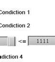
2 Number Name Alarm Screen Display Descriptions It has two types, automatic and manual. m When it t sets to Automatic: If the alarm is triggered, the t alarm screen will immediately pop up. When it sets to Manual: The display of alarmm screen is controlled c by setting the Action address to 2. B: Not to check [Continuous alarm address] Number Name Continuous Alarm Address Category Type Descriptions Uncheck this selection and the Read address will be disabled.. According to the alarm type (Bit or Word), W each alarm address can be triggered individually. It represents the alarm category, which is similar to alarm group. The supported group range is between 1 and 255. The type can be Bit or Word. Bit: Define thee Bit addresss for triggering alarms Word: Definee the Word address for triggering alarms The triggeringg method is determined by b its type, Bit or Word. When the type is Bit, please enter thee Bit address to trigger the alarm. When the type is Word, the alarm can c be triggered according to the conditional c statement. Conditional Descriptions Address = > < >= <= equal to greater g than less than greater than or equal to less than or equal to 24/61
3 Number Name Descriptions >,< out of the range Monitoring Address Alarm Screen Display <=,<= within the range It is used to display alarm messages set by users. Add %d1 after the alarm content you entered and when the value of monitoring address is 10, the alarm information shown in Alarm History Table will be Alarm10. When it sets to Automatic: When the alarm is triggered, the alarm screen will immediately pop up. When it sets to Manual: The display of alarm screen is controlled by setting the Action address to 2. 25/61


4 We have two pages in Alarm History Table, Details and Details-2. Details The control address provided in Details page allows users to arrange and select the alarm according to the set items. No. Name Action address Sort address Action addresss allows the specifiedd alarm can be displayed and acknowledged. Value Descriptions 0 Default status. No N action will be done. 1 Acknowledge the selected alarm in Alarm History Table. If the selected alarm has alarm screen andd the screen display is 2 set to Manual, when the value is 2, it wi ll display the alarm a screen. s The sort address will arrange and display the item specified by users. Value Descriptions Descriptions Default status. No action will be done. Arrange the item according to thee Trigger Time Arrange the t item according to the Acknowledge Time Arrangee the item according to the Recovery Time Arrange the item according to thee alarm countss Arrange the item according to the alarm type Arrange the item according to the alarm number 26/61
5 No. Name Descriptions Filter address Alarm Counter address Alarm group begin address Alarm group end address Filter address allows users to sift the specified items. Value Descriptions 0 Default status. It displays all triggered alarms. Hide the alarm with the function of [Recovery Time] and 1 [Confirmation Time]. 2 Hide the alarm with the function of [Recovery Time]. Hide the alarm with the function of [Recovery Time] or 3 [Confirmation Time]. Hide the alarm with the function of [Confirmation Time]. 5 6 It has to work with [Alarm Counter Address]. The displayed Alarm count is generated in accordance with the value of [Alarm Counter Address]. If the displayed alarm count is smaller than this value, then it will not show this alarm. It has to work with [Alarm group begin address] and [Alarm group end address]. When the alarm number is not within the range set by these two addresses, then the alarm will not be displayed. It has to work with [Filter address]. Only when the value of [Filter address] is 5, can the user enter the number of Alarm count. Example Behavior The Alarm count is 1, 2 or 3. Enter 1 and the Alarm History Table will display the alarm which alarm count is more than 1; Enter 2 and the Alarm History Table will display the alarm which alarm count is more than 2; Enter 3, the Alarm History Table will display the alarm which alarm count is more than 3. It has to work with [Filter address]. Only when the value of [Filter address] is 5, can the user enter the alarm type number. Example Behavior The number of alarm type is 1 and 5 Set [Alarm group begin address] to 1 and [Alarm group end address] to 3, the Alarm History Table will only display the alarms that belong to type 1. Set [Alarm group begin address] to 1 and [Alarm group end address] to 5, the Alarm History Table will display the alarms that belong to type 1 and 5. 27/61


![format in [Main] page to display the](/docs-images/95/125300188/images/6-13.jpg "confirmationn time.")


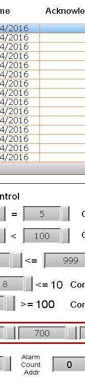
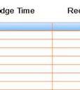
6 Details-2 The page allows users to check the display information of Alarm A History Table, arrange the column sequence and adjust the column width and font size. No. Name Number Trigger Time Alarm Message Confirmation Time Recovery Time Alarm Counts Descriptions Check this item and the Alarm History Table will display the alarm number. Check this item and the Alarm History Table T will show the alarm triggering time. Note: Please select the time format and date format in [Main] page to display the trigger time. Check this item to display the alarm message in Alarm History Table. Check this item and the Alarm History Table will show the Acknowledged alarm information. Note: Please select the time format and date format in [Main] page to display the confirmationn time. Check this item and the Alarm History Table T will show the Recovery alarm information. Note: Please select the time format and date format in [Main] page to display the recovery time. Check this itemm and the Alarm Historyy Table will display alarm triggering times. 28/61
7 No. Name Descriptions Users can use the Up and Down button to arrange the displaying order. Column display order Number / Time / Count font Column Width Users can determine the displayed number, time and font size for alarm count. Check the column that you desire to display and adjust the width. Its unit is Pixel. The function of Continuous alarm address is identical to the previous alarm setting. Thus, we take non-continuous alarm address as the example. Step 1: Go to [Options] > [Alarm Setup] and see the parameters setting as below. Uncheck [Continuous alarm address]. Select [Automatic] as Alarm screen display. Set up 10 alarms. Refer to the setting below: 29/61


8 Step 2: Create an Alarm History Table See the general setting of Main page below: See the setting of Details page below: 30/61


9 See the setting of Details-2: Step 3: Create the numeric entry element and maintained button of alarm setting and Alarm History Table. 31/61

![Then, go to [Options] > [Alarm Setup] to set the](/docs-images/95/125300188/images/10-2.jpg "screen of alarm number 1 and number 6 as screen")
![2. Step 5: Please go to [Initial Macro] to write](/docs-images/95/125300188/images/10-3.jpg "the command, which is shown as below.")
10 Step 4: Create one alarm screen as the sub-screen. Then, go to [Options] > [Alarm Setup] to set the screen of alarm number 1 and number 6 as screen 2. Step 5: Please go to [Initial Macro] to write the command, which is shown as below. When the HMI screen is opened, alarm 6 ~ 10 is on. 32/61
11 Step 6: Please compile and download all screens to the HMI. Step 7: After enabling the HMI screen, see the functions below: Alarm screen display In this example, [Alarm screen display] is set to [Automatic] hen the condition of alarm 6 is established, the alarm is On and the alarm screen shows automatically. If [Alarm screen display] is set to [Manual], you need to set [Action Address] to 2 to display the alarm screen. Please close the alarm screen. 33/61


12 Trigger alarm 1 ~ 5 by Bit Control Bit address triggers alarm 1 to 5. Thee Alarm History Table displays the alarm message set by users. If you change the value off [Monitoringg address], please trigger alarm 1 to 5 again.. The displayed alarm messagee will be changed in accordance with w the value. 34/61
13 Trigger Time When the condition of triggering the alarm by Bit address or Word address is established, the Alarm History Table will display the time and date that alarm has been triggered. Acknowledge Time To display the Acknowledge Time, please set Action address to 1. 35/61
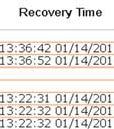
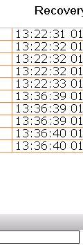
14 Recovery Time If the condition of triggering the alarm by Bit address or Word address is not established (such as Condition1 and Condition 2, see the figure below), then the Alarm History Table will display the Recovery Time. Action Address When Action Address is set to 0, the Alarm History Table has no action. When Action Address is set to 1, it will display the Acknowledge Time. (Weve already introduced Acknowledge Time before) When Action Address is set to 2 and [Alarm screen display] is set to [Manual], the system will display the alarm screen. (Weve already introduced Alarm Screen before) 36/61


![Time].](/docs-images/95/125300188/images/15-9.jpg "is 2, the")


15 Sort Address When the value of Sort Address is 0, the Alarm History Table will not do any sorting. When the value of Sort Address is 1, the alarm will be displayed according to the [Trigger Time]. When the value of Sort Address is 2, the alarm will be displayed according to the [Acknowled[ ge Time]. 37/61
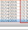
16 When the value of Sort Address is 3, the alarm will be displayed according to the [Recovery Time]. Since alarm No. 8 to 10 have not been cleared, these three will not be listed in Recovery Time. When the value of Sort Address is 4, the alarm will be displayed in ascending order (from least to greatest) according to the [Frequency]. 38/61
17 When the value of Sort Address is 5, the alarm will be displayed in ascending order (from least to greatest) according to the [Category]. When the value of Sort Address is 6, the alarm will be displayed in ascending order (from least to greatest) according to the [No.] 39/61
18 Filter Address When the value of Filter Address is 0, the Alarm History Table will display all alarms that had been triggered. When the value of Filter Address is 1, the Alarm History Table will hide the alarms that have set with the function of [Recovery Time] and [Acknowledge Time]. Before After 40/61
19 When the value of Filter Address is 2, the Alarm History Table will hide the alarms that have set with the function of [Recovery Time]. Before After 41/61
20 When the value of Filter Address is 3, the Alarm History Table will hide the alarms that have set with the function of [Recovery Time] or [Acknowledge Time]. Before After 42/61
21 When the value of Filter Address is 4, the Alarm History Table will hide the alarms that have set with the function of [Acknowledge Time]. Before After 43/61
22 When the value of Filter Address is 5, please set [Alarm count address] to 1. Before The Alarm History Table will hide the alarms which frequency are less than 1. Since the example below has no alarm that frequency is less than 1, all alarms will be displayed. After 44/61
23 When the value of Filter Address is 5, please set [Alarm count address] to 2. Before The Alarm History Table will hide the alarms which frequency are less than 2. After 45/61


![address]](/docs-images/95/125300188/images/24-5.jpg "to 1 and")


24 When the value of Filter Address is 6, please set [Alarm group begin address] to 1 and [Alarm group end address] to 3. Before If the alarm number is not within the setting range of [Alarm groupp begin address] and [Alarm group end address], the alarm will not be displayed. After 46/61


![begin address] to](/docs-images/95/125300188/images/25-4.jpg "3 and end")
![address] to 5.](/docs-images/95/125300188/images/25-5.jpg "Before If the")


25 When the value of Filter Address is 6, please set [Alarm group begin address] to 3 and [Alarm group end address] to 5. Before If the alarm number is not within the setting range of [Alarm groupp begin address] and [Alarm group end address], the alarm will not be displayed. After 47/61
26 3.3 The alarm export and import file format now supports Excel The previous supported format does not allow users to edit the file. DOPSoft provides Excel file format so that users can edit the alarm information. Export file format only supports Excel file format, such as.xls and.xlsx. As for the import file format, it supports.ini,.alm and Excel file format. Below shows the Excel file exported by DOP-B series HMI. Alarm Content 48/61


27 Alarm Setting Below showss the Excel file exported by DOP-W series HMI. Alarm Content 49/61


28 Alarm Setting 3. 4 Button of Sound Setting is now available inn DOP-W series HMI DOP-W127B and DOP-157B allows users to control the external and internal audio output switch respectively. Before that, users have to go to system directory to adjust the volume. Now, with the Sound Setting seriess HMIs havee built-in function of 1.55 watt audioo output. This newly added function button, userss can directly adjust the volume onn the edit screen. 50/61
Chapter 6. Alarm History Screen. Otasuke GP-EX! Chapter 6 Alarm History Screen 6-0. Alarm History Screen 6-1. Display Alarm History in List 6-2
 Chapter 6 Alarm History Screen Alarm History Screen 6- Display Alarm History in List 6-2 Let s Display Alarm History. 6-3 Read Data when Alarms Occur 6-2 Let s Read Data when Alarm Occur. 6-3 Let s Edit
Oracle Communications Performance Intelligence Center
 Oracle Communications Performance Intelligence Center System Alarms Guide Release 10.2.1 E77506-01 June 2017 1 Oracle Communications Performance Intelligence Center System Alarms Guide, Release 10.2.1
Getting Started with Live Exceptions
 Getting Started with Live Exceptions Live Exceptions provides alarm reporting by identifying problems that include delay, errors, failures, security, or configuration changes. The Live Exceptions Browser
Monitor Alarms and Events
 What Are Alarms and Events?, page 1 How are Alarms and Events Created and Updated?, page 2 Which Events Are Supported?, page 5 Set Alarm and Event Management Preferences, page 5 Interpret Event and Alarm
Monitor Alarms and Events
 This chapter contains the following topics: What Are Alarms and Events?, page 1 How are Alarms and Events Created and Updated?, page 2 Find and View Alarms, page 3 Set Alarm and Event Management Preferences,
Setting up and Managing Alarms in McAfee ESM 10.x
 McAfee SIEM Alarms Setting up and Managing Alarms in McAfee ESM 10.x Introduction McAfee SIEM provides the ability to send alarms on a multitude of conditions. These alarms allow for users to be notified
How to Configure the Alarm Action Outgoing Cell Call MultiLogger Application Note #14
 5 Gould Road, PO Box 2155 New London, NH 03257 Voice: (603) 526-9088 info@canarysystems.com www.canarysystems.com Overview How to Configure the Alarm Action Outgoing Cell Call MultiLogger Application Note
Operation Manual Fighter ProVision Software. Version: 0.0 Revision: 1
 Operation Manual Fighter ProVision Software Version: 0.0 Revision: 1 TABLE OF CONTENTS 1. Introduction 5 2. Software Installation 5 3. PC Users 6 3.1 Introduction 6 3.2 Default Code 6 3.3 Edit PC User
Alarms Updated 03/26/2018
 Updated 03/26/2018 Table of Contents Alarms Alarms in OneView...1 Types of Alarms...1 Setting up Alarms...2 Alarm Configuration...4 Customize Alarm Parameters...5 List of Configured Alarms...7 Acknowledging
Monitoring Operator Guide. Access Control Manager Software Version
 Monitoring Operator Guide Access Control Manager Software Version 5.10.10 2018, Avigilon Corporation. All rights reserved. AVIGILON, the AVIGILON logo, ACCESS CONTROL MANAGER, ACM, ACM VERIFY AND TRUSTED
Alarms and Events. Defining Alarm Conditions. Database-Generated Alarms
 9 Defining Alarm Conditions Database-Generated Alarms The LookoutDirect alarm service keeps track of error messages and any process elements you have defined alarm conditions for. You can define alarm
Managing Network Alarms and Events
 10 CHAPTER Prime Performance Manager allows you to view alarms and events that occur in your network. The following topics provide information about displaying network alarms and events: Displaying Active
Alarm Coordination Connected Components Building Block. Quick Start
 Alarm Coordination Connected Components Building Block Quick Start Important User Information Solid state equipment has operational characteristics differing from those of electromechanical equipment.
Welcome to MultiSight TM Vision Sensor Hands-On Lab
 Welcome to MultiSight TM Vision Sensor Hands-On Lab About This Hands-On Lab Welcome to the MultiSight TM Vision Sensor Hands-On Lab! This session provides you with an opportunity to explore the functionality
Alarm. Overview. Configuring FTAlarm Communications
 Contents Alarm 1 Overview...1 Configuring FTAlarm Communications...1 Setting up Communications...3 Adding Devices...3 DemoServer Supported Addresses...4 Modifying Devices...6 Deleting Devices...7 Alarm
ArchestrA Direct Connect
 Table of Contents ArchestrA Direct Connect... 1 Introduction... 1 ArchestrA Direct Connection... 1 ArchestrA Data Source Definition... 2 Data Source Definition... 2 Importing Alarms from ArchestrA... 6
Manage Alarms. Before You Begin CHAPTER
 CHAPTER 7 This chapter explains how to view and manage the alarms and conditions on a Cisco ONS 15310-CL. Cisco Transport Controller (CTC) detects and reports SONET alarms generated by the Cisco ONS 15310-CL
Manage Alarms. Before You Begin CHAPTER
 CHAPTER 9 This chapter explains how to view and manage the alarms and conditions on a Cisco ONS 15310-CL and Cisco ONS 15310-MA. Cisco Transport Controller (CTC) detects and reports SONET alarms generated
Planning Checklist for new IGSS projects
 Planning Checklist for new IGSS projects - 1 - Table of Contents Checklist for Planning a New IGSS Project... 3 Introduction... 3 Mandatory Checklist... 3 Mandatory Checklist... 5 Checkpoint 1: Understand
Alarm Monitoring and Management
 CHAPTER 10 This chapter describes Cisco Transport Controller (CTC) alarm management. To troubleshoot specific alarms, refer to the Cisco ONS 15310-MA SDH Troubleshooting Guide. Chapter topics include:
Manage Alarms. Before You Begin. NTP-E57 Document Existing Provisioning CHAPTER
 CHAPTER 9 Manage Alarms This chapter provides procedures required to view and manage Cisco ONS 15600 alarms and conditions. Cisco Transport Controller (CTC) detects and reports SONET alarms generated by
Manage Alarms. Before You Begin CHAPTER
 CHAPTER 9 Manage Alarms This chapter provides procedures required to view and manage Cisco ONS 15600 alarms and conditions. Cisco Transport Controller (CTC) detects and reports SONET alarms generated by
Smart Combiners Installation Guide. For Obvius A89DC-08 sensor modules
 For Obvius A89DC-08 sensor modules Introduction Large roof and ground arrays connect the panels into stings that are merged together in combiner boxes. Each string will typically consist of 10-15 panels
Sensor Cloud User Manual
 Sensor Cloud User Manual Table of Contents DEVICES TAB 4 1. DEVICE LIST 4 2. EXPAND ALL 4 3. EXPAND 4 4. STATUS 4 5. DEVICE 4 6. NAME 5 7. MONITORING INTERVAL 5 8. LAST ACTIVITY 5 9. VIEW 5 10. DELETE
Lesson 10: Configuring Events IGSS. Interactive Graphical SCADA System. Lesson 10: Configuring Events 1
 IGSS Lesson 10: Configuring Events Interactive Graphical SCADA System Lesson 10: Configuring Events 1 Contents of this lesson Topics: What is an event? The Event List Creating events Showing events as
SimpleComTools, LLC 1
 COM1000-SNMP s Simple Network Management Protocol (SNMP) is a popular network management tool. Traditionally, SNMP was designed and used to gather statistics for network management and capacity planning.
[ [ ADMIN PANEL USER GUIDE
 [ [ ADMIN PANEL USER GUIDE ADMIN PANEL USER GUIDE 2 Contents Logging In & Systems Overview 3 System Details 5 Analytics 6 View Alarms 8 Manage Alarms 9 Create Alarms 10 Device Reporting Alarm 11 Monthly
Alarm User Guide IGSS Version 12.0
 Alarm User Guide IGSS Version 12.0-1 - The information provided in this documentation contains general descriptions and/or technical characteristics of the performance of the products contained therein.
USER MANUAL FOR OPERATING SYSTEM
 P2262 ALARM PANEL USER MANUAL FOR OPERATING SYSTEM 21765-07 September 1999 Associated Controls (Aust) PTY. LTD. 29 Smith Street, Hillsdale, NSW, 2036. PH (02) 9311 3255, FAX (02) 9311 3779 Page 1 of 177
Oracle Communications Performance Intelligence Center
 Oracle Communications Performance Intelligence Center System Alarms User s Guide Release 10.1 E55927 Revision 2 October 2014 Oracle Communications Performance Intelligence Center System Alarms User s Guide,
Technical Publications. FactoryTalk Alarms and Events System Configuration Guide
 Technical Publications FactoryTalk Alarms and Events System Configuration Guide Important user information Read this document and the documents listed in the additional resources section about installation,
Running IGSS as an Operator, Part One
 Running IGSS as an Operator, Part One Contents Duration We want to see how a completed IGSS SCADA system appears to plant operator personnel to get an idea of the various elements in the system and how
HikCentral Web Client. User Manual
 HikCentral Web Client User Manual Legal Information User Manual 2018 Hangzhou Hikvision Digital Technology Co., Ltd. About this Manual This Manual is subject to domestic and international copyright protection.
TITLE RS20i Atmos & DTS:X Decoder Card (H693) Setup
 Setup") NUMER 1 of 12 Introduction The RS20i with the H693 card installed and software update V1.05.00 or above is capable of the following Dolby and DTS decoder and post processing technologies: Dolby Atmos Dolby
NUMER 1 of 12 Introduction The RS20i with the H693 card installed and software update V1.05.00 or above is capable of the following Dolby and DTS decoder and post processing technologies: Dolby Atmos Dolby
Making the Most of Alarms
 Making the Most of Alarms Leverage the alarm management features of MPA to address network performance problems more effectively. Blueprint to Leverage Alarms and Alerts Using Mitel Performance Analytics
Laptop / PC Programming Manual
 Laptop / PC Programming Manual Doc. # Fire PC Program rev B 01.07 This Document is property of Evax Systems, Inc. The Evax Fire Solutions Programmer Components 2 1.0 System Setup 4 1.1 Interface Setup
OnGuard 7.2 Resolved Issues
 UTC Fire & Security Americas Corporation, Inc. 1212 Pittsford-Victor Road Pittsford, New York 14534 Tel 866.788.5095 Fax 585.248.9185 www.lenel.com Contents OnGuard 7.2 Resolved Issues 1. Introduction...
I/A Series A 2 Software FoxAlert Alarm Manager
 Product Specifications I/A Series A 2 Software FoxAlert Alarm Manager PSS 21S-2B2 B4 Current Alarms Display Most Recent Alarms Display Summary Displays By Status Alarm History Display An Extensive Collection
Replaceable LED modules. Sleep or unattended mode. Auto-silence and auto-acknowledge
 Replaceable LED modules 11 Alarm Sequences as per ISA-18.1 standard Each channel/window fully field programmable RS232 or RS485 MODBUS-RTU communication Repeat relay for each window and multifunction relays
Manage Alarms. Before You Begin CHAPTER
 CHAPTER 9 Manage Alarms This chapter contains the procedures for viewing and managing the alarms and conditions on a Cisco ONS 15454 SDH. Cisco Transport Controller (CTC) detects and reports SDH alarms
HikCentral Web Client. User Manual
 HikCentral Web Client User Manual Legal Information User Manual 2018 Hangzhou Hikvision Digital Technology Co., Ltd. About this Manual This Manual is subject to domestic and international copyright protection.
OPERATOR S MANUAL MODEL AP15/AP15-1/AP15-2 PC-ALARM PANEL
 ap15_2manual04/22/13 Page 1 4/22/2013 1 Serial Number : Option: OPERATOR S MANUAL MODEL AP15/AP15-1/AP15-2 PC-ALARM PANEL Micro Seven, Inc. 1095-K N.E. 25th Hillsboro, OR 97124 U.S.A. phone: 503-693-6982
Halton SAFE / 7.14 user guide and installation instructions
 Halton SAFE / 7.14 user guide and installation instructions VERIFIED SOLUTIONS BY H A LTO N Enabling Wellbeing Table of contents 1 System description 3 2 User Accounts 4 3 Main menu 7 3.1 Main menu - Change
Managing Network Alarms and Events
 9 CHAPTER Prime Performance Manager allows you to view alarms and events that occur in your network. The following topics provide information about displaying network alarms and events: Displaying Active
VT8000 Series Replacement Procedure to Replace VT8000 Series Room Controller and Pair with ZigBee Pro Sensors
 VT8000 Series Replacement Procedure to Replace VT8000 Series Room Controller and Pair with ZigBee Pro Sensors Overview 2 This procedure shows how to replace VT8000 Room Controllers already installed, as
Lighting Xpert Insight User Manual
 Lighting Xpert Insight User Manual Table of Contents 1 About This Document... 3 1.1 Key Terms... 3 1.2 Related Fifth Light Documentation... 3 2 Lighting Xpert Insight Overview... 4 2.1 Key Features...
Alarm Monitoring and Management
 14 CHAPTER This chapter explains how to manage alarms with Cisco Transport Controller (CTC). To troubleshoot specific alarms, refer to the Cisco ONS 15454 SDH Troubleshooting Guide. Chapter topics include:
Energy Commander Paralleling Switchgear
 GE Consumer & Industrial Power Quality Energy Commander Paralleling Switchgear Paralleling Switchgear Paralleling is an operation in which multiple power sources, usually two or more generator sets, are
BeneVision Central Monitoring System. Quick Reference Guide
 BeneVision Central Monitoring System Quick Reference Guide NOTE: The Quick Reference Guide is not intended as a replacement to the Operating Instructions. Prior to operating equipment, the user must be
Intelligent Video Analysis
 Intelligent Video Analysis 1. Intelligent Video Analysis... 2 2. Unattended Object Detection... 6 3. Missing Object Detection... 7 4. Smoke and Fire detection... 8 5. Movement Direction Detection... 9
725B Configuration Software Manual
 725B Configuration Software Manual REV DATED DESCRIPTION AUTHOR APPROVED 0 09-03-10 First Issue P.Cartmell Page 1 of 80 SECTION 1 - SOFTWARE INSTALLATION... 5 725B ConfigurationSoftware Installation...
Manage Alarms. Before You Begin CHAPTER
 CHAPTER 8 Manage Alarms This chapter contains the procedures for viewing and managing the alarms and conditions on a Cisco ONS 15454. Cisco Transport Controller (CTC) detects and reports alarms generated
Operation Manual. Programmable Logic Controller
 Operation Manual Programmable Logic Controller Part No. 9983-0000-E01 / January 2018 OPERATION MANUAL TABLE OF CONTENTS CUSTOMER SERVICE 3 CONTACT INFORMATION 3 ORDER INFORMATION 3 INTRODUCTION 4 THE PROCESS
V1.21: (Required for All Dryers with Static Sampler or Incoming MST Sensor, Good for All Dryers)
") QuadraTouch Pro Software Update Change Log Official Release vs. Beta Release (How to tell): Tools -> System Tools -> System Information and look for Official Release or Beta Release in the bottom right
QuadraTouch Pro Software Update Change Log Official Release vs. Beta Release (How to tell): Tools -> System Tools -> System Information and look for Official Release or Beta Release in the bottom right
Moxa Proactive Monitoring User s Manual
 User s Manual Edition 2, May 2016 www.moxa.com/product 2016 Moxa Inc. All rights reserved. User s Manual The software described in this manual is furnished under a license agreement and may be used only
User Guide V3 4/13 Rev. C
 6280 Series TouchCenter Keypads User Guide 800-07602V3 4/13 Rev. C Table of Contents ABOUT THE TOUCHCENTER... 5 Introduction... 5 The TouchCenter Interface... 5 Navigating through the TouchCenter... 6
AIR CONDITIONER PERFORMANCE RATING
 HPRATE V5.1 AIR CONDITIONER PERFORMANCE RATING by G.L. Morrison MechLab The University of New South Wales.EDU.AU September 2012 Version 5.1 HPRATE 5 Air Conditioner Performance Rating 1 HPRATE AIR CONDITIONER
WorkstationST* Alarm Viewer
 GEI-100620U WorkstationST* Alarm Viewer Instruction Guide These instructions do not purport to cover all details or variations in equipment, nor to provide for every possible contingency to be met during
FieldServer Driver - Serial FS Notifier NCA
 Driver Version: 1.00 Document Revision: 15 Description FieldServer Driver - Serial FS-8700-98 Notifier NCA The NCA (Network Control Annunciator) Serial driver allows the FieldServer to record data from
WeatherLink for Alarm Output Addendum
 WeatherLink for Alarm Output Addendum Introduction This Streaming Data Logger is designed to provide an electrical interface between a Vantage Pro or Vantage Pro2 weather station console or Weather Envoy
FCD-wire Contents. List of Figures
 FCD-wire Contents FCD-X21 Configuration 1 Introduction... 1 2 Opening the FCD Application... 1 3 FCD Window... 2 4 FCD LEDs... 3 5 Configuration Operations... 4 FCD Info...4 FCD System Info...5 FCD Interface
QuadraTouch Pro Software Manual Dryer Control System
 QuadraTouch Pro Software Manual Dryer Control System Software is constantly changing. Make sure you are up to date with Sukup s newest software. New software and manuals are available for download at:
ND4000 Manual Marine Hydraulics
 ND4000 Manual Marine Hydraulics Version 1.0 May 2012 Page 1 Contents Line Counter Components... 3 Proximity Sensors... 3 Connecting the Proximity Sensors to the SSCD... 3 Fuse... 3 USB... 4 Computer Display...
User Guide V1 7/12 Rev. A
 6280 Series TouchCenter Keypads User Guide 800-07602V1 7/12 Rev. A Table of Contents ABOUT THE TOUCHCENTER...5 Introduction...5 The TouchCenter Interface...5 Navigating through the TouchCenter...5 About
Ademco Vista Alarm Panel
 System Galaxy Quick Guide CONFIGURATION AND OPERATION Ademco Vista Alarm Panel JAN 2018 SG 10.5.6 System Galaxy Quick Guide For Ademco Vista Panel Configuration & Operation 2nd edition JAN 2018 Information
i.c³ User Guide For Helmer i.series Ultra-Low Freezers A/A
 i.c³ User Guide For Helmer i.series Ultra-Low Freezers 360175-A/A Document History Revision Date CO Supersession Revision Description A 18 APR 2014* 9275 n/a Initial release. * Date submitted or change
VEEDER-ROOT CURRENT DATA STORAGE INTERFACE MANUAL. for. TLS-300 and TLS-350 UST Monitoring Systems. and
 VEEDER-ROOT CURRENT DATA STORAGE INTERFACE MANUAL for TLS-300 and TLS-350 UST Monitoring Systems and TLS-350R Environmental & Inventory Management System through Software Versions 15/115 Manual Number
FlameGard 5 UV/IR HART
 FlameGard 5 UV/IR HART HART Communication Manual The information and technical data disclosed in this document may be used and disseminated only for the purposes and to the extent specifically authorized
Procidia iware AlarmWorX32. AlarmWorX32 Viewer January 2010
 Procidia iware AlarmWorX32 AlarmWorX32 Viewer Siemens Protection AG 2008. notice All / Copyright rights reserved. notice Introduction / Contents Procidia iware is an operator interface software designed
DIH 1.2. System Alarms User Guide Revision A August 2012
 DIH 1.2 System Alarms User Guide 910-6518-001 Revision A August 2012 Copyright 2011 2012 Tekelec. All Rights Reserved. Printed in USA. Legal Information can be accessed from the Main Menu of the optical
OnGuard 7.1 Resolved Issues
 Lenel Systems International, Inc. 1212 Pittsford-Victor Road Pittsford, New York 14534 Tel 866.788.5095 Fax 585.248.9185 www.lenel.com Contents OnGuard 7.1 Resolved Issues 1. Introduction... 2 2. Access
Platform Services BACnet Alarm Management
 Description: Guide to understanding and setting up BACnet Alarms, visualizing real-time and historical BACnet alarms using AlarmWorX64 Viewer and logging them to SQL database using AlarmWorX64 Logger OS
Residential Smart Thermostat Qualified Products List Updated 5/1/2017
 Residential Smart Thermostat Qualified Products List Updated 5/1/2017 Approved Qualified Products Manufacturer Model 3 and 4 (NOT Lite) 3 rd Generation In order for products to meet the standards of the
Use of the application program
 Contents overview Use of the application program Use of the application program 1 1. Functional description 2 Switching on / off 2 Dimming brighter / darker 2 Dimming value (8 bit) 3 Status Switching (1
BRS Mechanically-Agitated BioReactor MA 100. Quick Reference Guide Ver2.0
 BRS Mechanically-Agitated BioReactor MA 100 Quick Reference Guide Ver2.0 Manufacturer: BioReactor Sciences 1150 Home Place Drive Lawrenceville, GA 30043 USA Phone: 404.307.7100 Email: info@bioreactorsciences.com
SCAN200E USER S MANUAL
 SCAN200E USER S MANUAL Code No. 2071 1052 rev. 1.4 Code No. 2071 1052 Rev. 1.4 Page 2/16 SCAN200E User s Manual Foreword This manual is for SCAN200E Controller running software version 2.03 or later. We
Interior Design Tutorial
 Chapter 4: Interior Design Tutorial In the Interior Design Tutorial, we ll pick up where we left off in the House Design Tutorial. The shell and basic structure of our plan is complete, but a lot of interior
Alarm Monitoring and Management
 CHAPTER 14 This chapter describes Cisco Transport Controller (CTC) alarm management. To troubleshoot specific alarms, refer to the Cisco ONS 15454 Troubleshooting Guide. Chapter topics include: 14.1 Overview,
1.1 Remote Annunciator Controller (RAC) using the one ATC-300+ connected via RS-485 network.
 using the one ATC-300+ connected via RS-485 network.") Remote Annunciator Controller (RAC) Instruction Sheet for Automatic Transfer Switches (ATS) Revision: 01 IB01602085E 1.1 Remote Annunciator Controller (RAC) using the one ATC-300+ connected via RS-485
Remote Annunciator Controller (RAC) Instruction Sheet for Automatic Transfer Switches (ATS) Revision: 01 IB01602085E 1.1 Remote Annunciator Controller (RAC) using the one ATC-300+ connected via RS-485
NGC-UIT2 MODBUS PROTOCOL INTERFACE MAPPING FOR NGC-30 SYSTEMS. Firmware versions up to V2.0.X
 NGC-UIT2 MODBUS PROTOCOL INTERFACE MAPPING FOR NGC-30 SYSTEMS Firmware versions up to V2.0.X INDUSTRIAL HEAT TRACING SOLUTIONS EN-RaychemNGCUIT2Protocol-IM-H57880 06/15 1/32 Contents Section I Introduction
Elderly Care Alarm System
 Introduction 24/7 Peace of mind for your family The GSM Elderly Care Alarm System is a new released smart solution for take care of senior, aged, elder or disabled people on their daily life. Big LED display
rvm4c Installation Guide Remote Video Module
 rvm4c EN Installation Guide Remote Video Module rvm4c Installation Guide Installation Diagrams EN 2 Installation Diagrams for the Transmitting Unit rvm4c Installation Guide Basic Hardware Installation
Avigilon Control Center 5 System Integration Guide
 Avigilon Control Center 5 System Integration Guide for Paxton Net2 Access Control Systems 2014 Avigilon Corporation. All rights reserved. Unless expressly granted in writing, no license is granted with
MIRA Black Start User Guide. Monitoring Analytics, LLC. Version 1.0: April 18, Monitoring Analytics
 MIRA Black Start User Guide Monitoring Analytics, LLC Version 1.0: April 18, 2016 Monitoring Analytics 2016 www.monitoringanalytics.com 1 Table of Contents MIRA Black Start User Guide... 3 1 Getting Started
Security Escort Central Console Software SE2000 Series
 Release Notes Security Escort Central Console Software SE2000 Series Table of Contents 1 Security Escort v2.18.1.0... 2 1.1 Enhancements... 2 1.2 Errors Fixed... 2 1.3 Known Limitations and Restrictions...
Avigilon Control Center System Integration Guide
 Avigilon Control Center System Integration Guide with Gallagher Command Centre INT-CARDAX-C-Rev3 Copyright 2013 Avigilon. All rights reserved. No copying, distribution, publication, modification, or incorporation
Alarm handling by SMS in ALERT
 Micromedia International Alarm handling by SMS Author: Jens Eberle Pages : 9 Company: Micromedia International Date : 29/10/2013 Version : 1.1 Réf. : Alarm Handling by SMS.docx [Commentaires ] Alarm handling
P2267 NETWORK INTERFACE
 P2267 NETWORK INTERFACE USER MANUAL FOR OPERATING SYSTEMS: 22031-03 23636-01 October 2009 Associated Controls (Australia) Pty. Limited 2-4 Norfolk Road Greenacre, NSW, 2190. PH +61 2 9642 4922, FAX +61
Sentient. Downloader Manual D4854
 Sentient Downloader Manual D4854 Dycon Ltd Tel: +44 (0)1443 471 060 Fax: +44 (0)1443 479 374 Cwm Cynon Business Park Mountain Ash CF45 4ER - UK www.dyconsecurity.com sales@dyconsecurity.com TABLE OF CONTENTS
Honeywell Total Connect Remote Services
 Honeywell Total Connect Remote Services Basic User Guide With Honeywell Total Connect Remote Services, you can stay connected and in control of your home or business whenever you want, wherever you are.
SETTING UP DSC INTEGRATION THROUGH ENTRAPASS
 DN1914-1005 SETTING UP DSC INTEGRATION THROUGH ENTRAPASS The purpose of this application note is to configure the EntraPass system to integrate with the DSC PowerSeries tm intrusion panel With EntraPass
PYROSOFT. Software for DIAS infrared cameras in industry and research & development. Standard and application specific software Overview & Features
 PYROSOFT Software for DIAS infrared cameras in industry and research & development Standard and application specific software Overview & Features w w w. d i a s - i n f ra r e d. d e PYROSOFT Compact,
Alarm description DECS Contents
 Alarm description DECS 2.0 1.0 Contents 1.0 Contents...1 2.0 Alarm menu...2 2.1 List of alarms...2 2.2 Selecting Priority...2 2.3 Selecting Status...2 2.4 Specifying Event Text...3 2.5 Selecting Source...3
IndigoVision. Gallagher Integration Module. Administrator's Guide
 IndigoVision Gallagher Integration Module Administrator's Guide Gallagher - Integration Module THIS MANUAL WAS CREATED ON THURSDAY, MARCH 22, 2018. DOCUMENT ID: IU-IM-MAN008-6 Legal Considerations LAWS
AnthropologischeGesellschaftWien. Model Building. Gabriel Wurzer, Vienna University of Technology
 AnthropologischeGesellschaftWien Model Building Gabriel Wurzer, Vienna University of Technology www.iemar.tuwien.ac.at PREFACE or: filling the academical quarter When things go wrong, or: HOW TO DEBUG
C. The system shall be capable of turning luminaires on/off (where supported by the luminaire) as well as full range dimming.
 as well as full range dimming.") SECTION 260943 SPECIFICATIONS - Wireless Network Lighting Controls. PART 1 - GENERAL 1.1 RELATED DOCUMENTS 1.2 SUMMARY AND KEY SYSTEM DIFFERENTIATORS A. The lighting control system specified herein shall
SECTION 260943 SPECIFICATIONS - Wireless Network Lighting Controls. PART 1 - GENERAL 1.1 RELATED DOCUMENTS 1.2 SUMMARY AND KEY SYSTEM DIFFERENTIATORS A. The lighting control system specified herein shall
Weekly Testing of Dedicated Stairwell Pressurization Fans- Metasys System Extended Architecture Code No. LIT
 Weekly Testing of Dedicated Stairwell Pressurization Fans- Metasys System Extended Architecture Code No. LIT-1201739 Release 1.2 Issued Date July 30, 2004 Supersedes Document Introduction.................................................
Simplex Panel Interface Guide
 Simplex Panel Interface Guide February 2016 SATEON Software Integrations Simplex Panel Interface Guide Issue 1.0, released February 2016 Disclaimer Copyright 2016, Grosvenor Technology. All rights reserved.
Security Management System Configuring TCP-IP MODBUS Inputs
 Security Management System Configuring TCP-IP MODBUS Inputs This document explains the configuration of TCP/IP MODBUS devices in the Security Management System Server software. A) Configuring TCP-IP MODBUS
 Configuring Messages and Alarms in WinCC (TIA Portal) Extension with S7-1200/S7-1500 WinCC V14 SP1 https://support.industry.siemens.com/cs/ww/en/view/62121503 Siemens Industry Online Support Siemens AG