Life Safety Dampers Selection and Application Manual
|
|
|
- Howard Bruno Henry
- 6 years ago
- Views:
Transcription


1 Life Safety Dampers Selection and Application Manual Ceiling Radiation Dampers Fire Dampers Combination Fire Smoke Dampers Smoke Dampers August
2 2 Table of Contents HOW TO USE THIS MANUAL DAMPER APPLICATION 3 Fire Damper Application Smoke Damper Application Combination Fire Smoke Damper Application Corridor Ceiling Combination Fire Smoke Damper Application DAMPER SELECTION 5 Selection Process Key Points to Remember ACTUATOR SELECTION 7 Selection Process Actuator Mounting Options Key Points to Remember SLEEVE REQUIREMENTS 9 Sleeve Thickness Sleeve Length Key Points to Remember SPACE REQUIREMENTS FOR PROPER INSTALLATION 10 Key Points to Remember DAMPER OPTIONS 11 Control Options Security Bar Options Transition Options Key Points to Remember INSTALLATION REQUIREMENTS 15 Combination Fire Smoke Damper Installation Smoke Damper Installation Actuator Installation Damper and Actuator Maintenance Key Points to Remember SPECIAL INSTALLATION CASES 17 Maximum Damper Size Limitations Horizontal Fire Smoke Damper in a Non-Concrete Barrier AMCA Mullion System What if a Damper Cannot be Installed per the Manufacturer s Installation Instructions? What if a Damper Cannot be Installed in the Wall? Steps to Take When an Unapproved Installation Must be Provided CEILING RADIATION DAMPERS 20 Ceiling Radiation Damper Application Key Points to Remember CODES AND STANDARDS 21 Compliance with the Applicable Building Codes The National Fire Protection Association Code and Standard Making Organizations Modifications to Life Safety Dampers UL STANDARDS 22 MOST COMMONLY ASKED QUESTIONS 25 MODEL DEFINITION 26 DRIVE ARRANGEMENT DEFINITION 27 THE GREENHECK DIFFERENCE 27
3 HOW TO USE THIS MANUAL This manual can be utilized in a variety of ways. It can be studied from cover to cover as a textbook on fire, smoke, combination fire smoke dampers, and ceiling radiation dampers or it can be used as a reference on one or more of the following topics: Fire, smoke, or combination fire smoke damper applications Selection of the correct damper and actuator Damper and actuator installation requirements Ceiling radiation dampers Codes and standards that regulate and qualify fire, smoke, or combination fire smoke dampers There are answers to a list of Most Commonly Asked Questions at the end of this manual and summaries of Key Points to Remember at the end of each section. DAMPER APPLICATION Fire Damper Application Fire dampers are required by all building codes to maintain the required fire resistance ratings of walls, partitions, barriers and floors when they are penetrated by air ducts or other air transfer openings. One of the basic requirements of building fire protection is the compartmentation or dividing up of buildings using fire rated walls, floors, or other partitioning methods. This compartmentation concept is intended to contain any fire to the compartment of fire origin and thereby minimize damage to property and protect the lives of people living and/or working in the building. A duct or ventilation opening in any of the fire rated partitions would permit a fire to spread from the compartment of origin to adjoining compartments or spaces. Fire dampers are installed in these duct or ventilation openings. They close automatically upon detection of heat by a heat-responsive device (usually by the melting of a fusible link at 165 F [74 C]), blocking the opening and preventing the spread of fire into the adjoining compartment. UL (Underwriters Laboratories) Classified fire dampers are tested to UL Standard 555 Fire Dampers. They are always supplied with an appropriate UL label. There are significant factors required that must be considered when specifying a fire damper for a certain application. These are: Fire Resistance Ratings Two fire resistance ratings are available: 1½ hours and 3 hours. Walls, floors, or partitions with fire resistance ratings of 3 hours or more require fire dampers with a 3 hour rating. Fire resistance ratings less than 3 hours require 1½ hour rated fire dampers. (Reference 2015 International Building Code, section ). Airflow Closure Ratings Fire dampers can be either STATIC or DYNAMIC rated. STATIC rated fire dampers have no airflow closure rating and can only be applied in HVAC systems that are designed to shut down automatically in the event of a fire. DYNAMIC rated fire dampers carry a UL 555 rating to close while the HVAC system is running. DYNAMIC rated fire dampers carry both an airflow velocity (ft/min) rating and a pressure differential rating (in. wg) and should be selected to operate against the conditions they will see in their application. DYNAMIC rated fire dampers are always an appropriate selection. Fire rated partitions contain fire damage to the compartment of fire origin. Unprotected partition Partition protected by fire damper 3
4 Mounting Orientation Fire dampers are required to pass a test for vertical mount and/or a test for horizontal mount. Dampers need to be installed in the correct orientation to ensure life safety and proper fire protection. Each vertical or horizontal mount damper carries its own label. These mounting orientations are not interchangeable. Smoke Damper Application Smoke dampers have two general applications. They may be applied in a Passive Smoke Control System where they simply close and prevent the circulation of air and smoke through a duct or ventilation opening in a smoke barrier. They also may be applied as part of an Engineered Smoke Control System designed to control the spread of smoke using walls and floors as barriers and using the building s HVAC system and/or dedicated fans to create pressure differences. Higher pressures surround the fire area and prevent the spread of smoke from the fire zone into other areas of the building. Smoke dampers are motorized with electric or pneumatic actuators and may be controlled by a smoke or heat detector signal, a fire alarm signal, or by the building control system to accomplish the intent of the design. UL Classified smoke dampers are tested to UL Standard 555S Smoke Dampers and are always supplied with an appropriate UL label. It is necessary to determine which of the following ratings are required when applying a UL smoke damper: Leakage: Class I (lowest leakage), Class II, or Class III (highest leakage). The 2015 International Building Code (IBC), section requires a minimum of Leakage Class II. Leakage Class I is recommended to provide the safest level of protection. Elevated Temperature: 250 F or 350 F (121 C or 177 C) is the temperature at which the actuator must be able to operate the damper and the temperature at which the leakage test is conducted. Most often 350 F (177 C) is selected for the highest level of safety. Velocity and Pressure: UL 555S requires each smoke damper with its installed actuator to be rated for operation to open against a specific pressure differential (in. wg) and to close against a specific velocity of airflow (ft/min). Dampers should be selected to operate at the pressures and velocities they will see in their application, with a minimum of 4 in. wg (1 kpa) and 2000 ft/min (10.2 m/s). Supply Fan Supply Air Horizontal Label Vertical Label Typical Non-Smoke Zone Damper positioned to create positive pressurization Typical Fire Smoke Zone Damper positioned to create negative pressurization Return/ Exhaust Fan Return/Exhaust Air Combination Fire Smoke Damper Application A combination fire smoke damper performs the function of both a fire damper and a smoke damper. Building layouts and designs often combine fire and smoke rated partitions and barriers requiring the installation of both a fire damper and smoke damper at the same location. Combination fire smoke dampers must be qualified under UL Standard 555 as a fire damper AND under UL Standard 555S as a smoke damper. The considerations listed above for both of these damper types apply to the selection and application of combination fire smoke dampers. Typical Engineered Smoke Control System Smoke is contained to the fire zone by higher pressures in adjacent zones Corridor Ceiling Fire Smoke Damper Application UL has established a separate classification to list dampers for this application. UL 555 and 555S qualification plus additional tests in actual corridor ceiling construction are required by UL to classify a combination fire smoke damper. Typical Smoke Damper 4
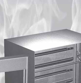
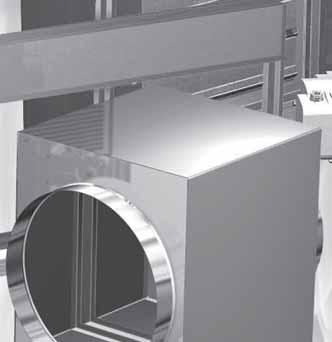
5 DAMPER SELECTION Selection Process Five basic decisions are required to select a fire, smoke, or a combination fire smoke damper. The process involves defining requirements for: Blade Style - Curtain, 3V, airfoil, or round blade styles Fire Resistance Rating - 1½ or 3 hours based on code requirements and building design (2015 International Building Code, section ) Leakage Rating - Class I, II, or III (2015 International Building Code, section , requires a minimum of Leakage Class II) Elevated Temperature Rating F or 350 F (121 C or 177 C) 2015 International Building Code, section , requires a minimum of 250 F (121 C) Operational Ratings - Velocities and pressure differentials the damper will see in its application Blade Style Blade style decisions are based on application, velocity, and the pressure required for your system. The curtain blade style is appropriate for fire damper applications only and airflow velocities up to 4,000 ft/min (20.3 m/s). The 3V blade style is appropriate for use in airflow velocities up to 2,000 ft/min (10.2 m/s). Airfoil style blades are appropriate for use with airflow velocities up to 4,000 ft/min (20.3 m/s). A round style blade is appropriate for use in airflow velocities up to 3,000 ft/min (15.2 m/s) where you need to connect to round ductwork or where minimum pressure drop is desired. Pressure loss information is available at Fire Resistance Rating Fire and combination fire smoke dampers installed in walls, floors, or partitions are required by the applicable building code to have a fire resistance rating. Select a fire damper and combination fire smoke damper with a 1½ hour rating for use with a wall, floor, or partition with a less than 3 hour fire resistance rating. If the wall, floor, or partition has a fire resistance rating of 3 hours or more, the damper must have a rating of 3 hours. Interlocking Curtain Blades 3V Blade Steel Airfoil Blade Extruded Aluminum Airfoil Blade Type of Penetration Less than 3 hour fire resistance rated assemblies 3 hour or greater fire resistance rated assemblies Minimum Damper Rating (hours) 1½ 3 Round Blade If the barrier is not required to have a fire resistance rating, then no fire rating is required and a smoke damper may be selected (see 2015 International Building Code, section ). Smoke dampers may be required in corridor penetrations in accordance with 2015 International Building Code Leakage Rating UL Standard 555S identifies three leakage classes as follows: Leakage Class Maximum Leakage in cfm/ft 2 Maximum Leakage in cmh/m 4 in. 8 in. 1 2 kpa Class I Class II Class III Designers are generally advised to select the lowest leakage class. Typical Fire Damper 5
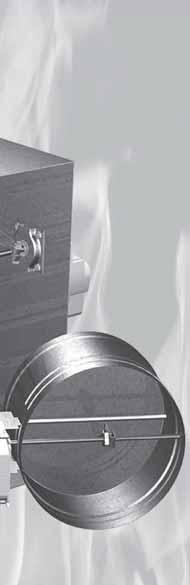
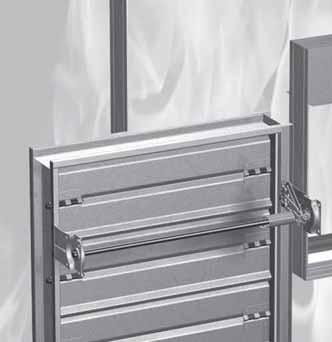
6 Even though the 2015 edition of the International Building Code requires a minimum of Leakage Class II, there are some applications where a higher leakage class can be used. Leakage Class I (the lowest leakage) rated dampers are available from most manufacturers ensuring appropriate competition if Class I is selected. Elevated Temperature Rating The purpose of a building Smoke Control System is to keep certain areas of a building free from smoke during the early phases of a fire so building occupants can safely evacuate and firefighters can more easily locate and attack the fire. The UL 555S Elevated Temperature Rating is a 30 minute emergency rating to ensure the damper (and its installed actuator) can resist a short exposure to elevated temperature and still operate as required. Although 250 F (121 C) is the minimum elevated temperature rating, 350 F (177 C) is available for all Greenheck fire smoke damper models at no additional cost. The 2015 International Building Code (IBC) requires the minimum 250 F (121 C) rating. Modulating actuators and extruded aluminum blade models are rated at 250 F (121 C). All Greenheck FSD (combination fire smoke) dampers and SMD (smoke) damper models are UL 555 and UL 555S rated to 350 F (177 C). Operational Rating Operational ratings are dependent on the damper s size and installed actuator. Both UL 555 and UL 555S require a combination fire smoke damper and its installed actuator be rated for a maximum airflow rate (velocity in ft/min) through the open damper and a maximum pressure (in. wg) across the closed damper. The installed actuator must operate the damper open and close against these rated velocities and pressures. Greenheck combination fire smoke dampers with 3V blades are rated up to 2,000 ft/min (10.2 m/s) and pressure up to 6 in. wg (1.5 kpa). The airfoil blade models are rated up to 4000 ft/min (20.3 m/s) and pressure up to 8 in. wg (2 kpa). Dynamic rated fire dampers are typically rated without actuators. Round, curtain style fire, and multi-blade fire dampers meet the requirement of UL 555 with airflow ratings up to 4,000 ft/min (20.3 m/s) and pressure up to 10 in. wg (2.5 kpa). Considerations of blade style, fire resistance rating, and leakage rating lead directly to the selection of an appropriate Greenheck fire, combination fire smoke or smoke damper model. Once an appropriate damper model has been selected, its elevated temperature and operational ratings should be compared with the requirements for these ratings. Typical Multi-Blade Fire Damper Typical Combination Fire Smoke Damper RRL and actuator act to close damper when temperatures exceed thermostat ( F [ C]) to protect the duct from fire and smoke penetration. Typical Round Combination Fire Smoke Damper KEY POINTS TO REMEMBER Codes require fire dampers in most applications where the barrier being penetrated to have a required fire resistance rating of 2 hours or more. Code requirements vary. Always follow the requirements of the applicable building code. Smoke dampers are required where a duct penetrates a smoke partition or barrier within a building, in a corridor penetration AND when any damper performs a function in an engineered smoke control system. 1½ hour fire dampers appropriately protect walls, partitions, and barriers with fire resistance ratings less than 3 hours. 3 hour fire dampers are required if a barrier s fire resistance rating is 3 hours or more. STATIC rated fire dampers can be applied only if the HVAC system is automatically shut down in the event of a fire emergency. DYNAMIC rated fire dampers can be applied in all HVAC systems. When selecting a fire or combination fire smoke damper there are five basic decisions which affect final model selection: blade style, fire resistance rating, leakage rating, elevated temperature, and operational ratings. 6
7 ACTUATOR SELECTION A smoke damper s function is to OPEN or CLOSE to either seal off an opening, or to create a pressure difference to prevent the spread of smoke. The damper actuator drives the damper to OPEN or CLOSE. When a smoke damper or a combination fire smoke damper is selected, a very important part of the process is the selection of an appropriate damper actuator. Qualification of the damper under UL Standards 555 and 555S involves testing both the damper and its installed actuator. This means the actuator must be selected from the damper manufacturer s list of actuators that have been tested with and are UL Listed for the smoke or combination fire smoke damper model that will be furnished. Actuators must be furnished factory-installed by the damper manufacturer. Selection Process Actuators may be ELECTRIC or PNEUMATIC. Damper size limitations are based on the velocity of airflow through the open damper and the pressure differential across the closed damper. Actuator Type Select either ELECTRIC or PNEUMATIC actuators based on the type of control system that will operate the dampers and any other appropriate factors. Most electric actuators are available in 24VAC, 24VDC, 120VAC, or 230VAC. Pneumatic actuators require psi ( kpa) control air. Operation may be two position, three position, balancing or modulating control. Consult Greenheck for other voltage, frequency, or control requirements. Actuator Model Each specific actuator model will have a series of maximum damper size ratings depending on the damper model, airflow velocity through the open damper, temperature rating required, and maximum pressure differential across the closed damper. As an example, damper size limitations for two of the more commonly used actuators installed to operate Greenheck s model FSD-311 (airfoil blade combination fire smoke damper) with a 4 in. wg (1 kpa) maximum pressure differential are as follows: Electric Actuator Damper Actuator Mounting Location Velocity ft/min (m/s) Temperature F ( C) Maximum Size W x H in. (mm) Siemens (pneumatic) External or Internal External 2000 (10.2) 3000 (15.2) 350 (177) 350 (177) 24 x 24 (610 x 610) 18 x 18 (457 x 457) Honeywell MS4104, 4604, 8104 (24V, 120V, 230V electric) External or Internal External 2000 (10.2) 3000 (15.2) 350 (177) 350 (177) 24 x 24 (610 x 610) 18 x 18 (457 x 457) Pneumatic Actuator Greenheck damper representatives have or can obtain the necessary information to properly apply all actuators that are UL Qualified for use with Greenheck combination fire smoke dampers. Greenheck s Computer Aided Product Selection (CAPS) program contains the necessary data and greatly simplifies actuator selection. 7
8 Actuator Mounting Options Actuators must be factory mounted. Factory mounting options include external (on a damper sleeve or sideplate) or internal. Internal actuator mounting (where the actuator is mounted inside a duct) should be avoided if possible, as it increases the difficulty of actuator inspecting, testing, and servicing. Factory Mounting - External on a Sleeve As all combination fire smoke dampers require a sleeve for proper installation, the most practical choice is for the damper to be furnished by the factory complete with a sleeve and the actuator installed on the outside of the sleeve. This is the standard and recommended actuator mounting option for combination fire smoke dampers. Factory Mounting - External on a Sideplate Smoke dampers do not always require sleeves for proper installation. External installation of the actuator can be provided using a sideplate (usually the full height of the damper as illustrated). These dampers are installed in a slotted duct section with the sideplate covering the slot in the side of the duct. Full height sideplates may not be practical on large smoke dampers (particularly multi-section assemblies). Factory Mounting - Internal Most actuators can be mounted internally (in the airstream) to accommodate those installations where space constraints prevent the more desirable external installation. There are limitations on small sizes with options (such as the TOR, RRL/OCI, OCI or PRV), which occupy much of the available internal space. Damper with sideplate actuator externally mounted. Damper mounted in sleeve with actuator externally mounted. Damper mounted in sleeve with actuator internally mounted. KEY POINTS TO REMEMBER Actuators may be electric or pneumatic and may be two position, three position, balancing or modulating control. An actuator s damper size rating is dependent on the airflow velocity and pressure difference for each specific damper. The most practical way to supply combination fire smoke dampers is with a factory-furnished sleeve with the actuator mounted externally. Sideplate external actuator mounting is available on smoke and combination fire smoke dampers. 8
9 SLEEVE REQUIREMENTS All UL fire and combination fire smoke damper listings require that the damper be mounted in a sleeve of the required gauge and length prior to installation. The sleeved damper is installed in the wall or floor opening and retained as part of the structure by angles attached to the sleeve. The sleeved damper becomes part of the wall (or floor) structure and ducts are attached to the sleeve. UL requires that connecting ducts terminate at each end of the damper sleeve. Sleeve Thickness Sleeve gauge or thickness requirements depend on the size of the damper and on the type of duct-to-sleeve connections used. UL allows two types of duct-to-sleeve connections: RIGID and BREAKAWAY. A RIGID connection is, by UL s definition, any connection that has not been qualified as a BREAKAWAY connection. A number of qualified BREAKAWAY connections, as well as procedures for qualifying additional BREAKAWAY connections, are defined in UL Standard 555. All qualified BREAKAWAY connections must be described in the damper manufacturer s fire and combination fire smoke damper installation instructions. Table 1 provides minimum fire and combination fire smoke damper sleeve thickness requirements as defined by UL 555. Sleeve Length The required sleeve length depends on the thickness of the wall or floor being penetrated, and the space constraints imposed by the damper s actuator, Sleeve Gauge 14 ga. (0.075 in.) - 10 ga. (0.138 in.) [2mm - 3.5mm] 16 ga. (0.060 in.) [1.5mm] 16 ga. (0.060 in.) [1.5mm] 18 ga. (0.048 in.) [1.2mm] 20 ga. (0.036 in.) [0.9mm] 22 ga. (.030 in.) [0.76mm] 24 ga. (0.024) [0.6mm] 26 ga. (0.018 in.) [0.46mm] accessories, and options. UL imposes the following maximum sleeve length restrictions for combination fire smoke and multi-blade fire dampers: Sleeves may not extend more than 6 in. (152 mm) beyond the wall or floor on the non-actuator side (B dimension, Figure 1). On the actuator side of the opening (A dimension, Figure 1), the sleeve may extend 16 in. (406 mm). On fire dampers, sleeves shall extend a maximum of 6 in. (152 mm) beyond the wall or floor opening on each side. If the sleeve is provided with an access door, it may extend 16 in. (406 mm) on the side equipped with the access door. Sleeves must extend far enough beyond each side of the wall or floor to accommodate the retaining angles required for installation (usually 1½ in. [38 mm]) plus whatever is required for the duct-tosleeve connections (usually a minimum of 1½ in. [38 mm]). On the actuator side of the damper, the sleeve must be long enough to accommodate the actuator and accessories (A dimension, Figure 1). Table 1: Minimum Sleeve Thicknesses for Fire/Combination Fire Smoke Dampers Duct Dimension All duct sizes 36 in. (914mm) max. width 24 in. (610mm) max. height 24 in. (610mm) diameter All duct sizes 85 in. (2159mm) wide and over 55 in in. wide (1397mm mm) 31 in in. wide (787mm mm) 13 in in. wide (330mm - 762mm) 12 in. wide and under (305mm) Sleeve thickness must not be less than the gauge of the connecting duct. UL Standard 555 requires all ducts to terminate at fire damper sleeves. Actuator and accessories are mounted in this general area A 16 in. Max. Type of Duct to Sleeve Connection Permitted Damper Overall Sleeve Length Rigid or Breakaway Rigid or Breakaway Breakaway only T w B 6 in. Max. L min Figure 1: Sleeve Length Considerations 9
10 Figure 2 provides a means of estimating the minimum required sleeve length. Figure 3 provides typical sleeve lengths for given wall thicknesses. Figure 2: Minimum Sleeve Length Equation L min = A + B + T w L min = minimum sleeve length A = B = length of sleeve beyond wall (actuator side) length of sleeve beyond wall (non-actuator side) T w = wall thickness Figure 3: Typical Sleeve Length Requirements Wall or Floor Thickness Inches (mm) 4-6 ( ) 7-10 ( ) ( ) Sleeve Length Required Inches (mm) ( ) ( ) ( ) Greenheck s standard and most economical sleeve lengths are 16, 21, and 24 inches (406, 533, and 610 mm). KEY POINTS TO REMEMBER All fire and combination fire smoke dampers require sleeves for installation. The damper and sleeve are part of the wall. The ductwork terminates at each end of the damper sleeve. Damper size and RIGID or BREAKAWAY duct-to-sleeve connections determine the required sleeve thickness. The sleeve thickness shall not be less than the thickness of the connecting duct. SPACE REQUIREMENTS FOR PROPER INSTALLATION When a combination fire smoke damper is being installed, it must fit in the space available with room for wiring or piping. After the damper is installed, it must work properly and perform its important function for the life of the building. The damper, its actuator, and any optional accessories must be accessible for inspection, testing, and service (per NFPA 80, 90A, 92A, 101 and 105). Actuators and other components may require replacement as part of a planned maintenance program. While space requirements are somewhat predictable, spending a little time making sure everything will fit can eliminate many problems and save money for all concerned. The damper actuator and optional accessories are normally externally mounted on one side of the damper s sleeve. It is Greenheck s standard practice for these items to be on the right side of the sleeve. This is a right hand mount. When specifically requested, they may be mounted on the left side of the sleeve, as shown, which we call a left hand mount. As many combination fire smoke dampers have a top or this side up designation, and cannot be turned upside down, it is very desirable to clearly define the right or left hand actuator mounting requirements when the damper order is released for fabrication. A capability unique to Greenheck s combination fire smoke dampers allows dampers to be turned upside down (when installed vertically or horizontally) to overcome unforeseen clearance problems. Greenheck designed its UL Qualified combination fire smoke dampers not to have a "top" or "this side up" designation to provide flexibility for the installing contractor. Greenheck s combination fire smoke damper product submittal and our Computer Aided Product Selection (CAPS) program includes dimensional information describing space requirements for damper actuators and optional accessories. If space above or below the damper sleeve is limited, special note should be taken as Retaining Angle Represents space allowance required for externally mounted actuator and controls Wall or Floor Retaining Angle Sleeve Duct 10


11 some standard actuator mountings require clearance in this area. In most cases, clearance problems can be accommodated if they are defined before production of the dampers. Clearance problems discovered after the dampers are on the jobsite can be extremely costly. Internal actuator mounting should be considered only as a last resort solution to clearance problems. Even with internal actuator mounting, external clearances may still be required. Access to the actuator for wiring, piping, inspection, and service must be provided. Internal mounting may not be available on smaller size dampers because there simply is not enough room to fit the actuator inside the sleeve. KEY POINTS TO REMEMBER Actuators and optional accessories occupy space outside of the combination fire smoke damper sleeve or sideplate, and appropriate clearances are required. Actuators mounted externally will be right hand mounted as standard, but can be left hand mounted upon request. Internal actuator mounting is not a good solution to lack of clearance and should not be used unless there is no other solution. DAMPER OPTIONS Closure Device Smoke and combination fire smoke dampers without options are fairly straight-forward devices. The damper is linked to its actuator, which moves the damper to its open or closed position in response to signals from the building control system, fire alarm system, smoke alarm system or the electric heat-responsive sensing device on the damper itself. Fire dampers and round combination fire smoke dampers are equipped standard with a fusible link. Fusible links meet UL33 requirements. Combination fire smoke dampers are equipped standard with a Reusable Resettable Link (RRL), an electric heat-responsive sensing device. The RRL has a fixed temperature setting (usually 165 F [74 C]) and performs the same function as a fusible link, which is to sense an abnormally high temperature (presumed to be caused by a fire) and allow the damper to close to prevent the spread of fire and smoke. The sensor interrupts power to the actuator, causing the actuator s spring return mechanism to close the damper. If the damper is equipped with a pneumatic actuator, a PRV (pneumatic relief valve) or an EP switch (electro-pneumatic solenoid valve) is used in conjunction with an RRL to control the pneumatic damper. An advantage of the RRL is that it can be reset (by pushing a reset button at the sensor), eliminating the need to replace a fusible link each time on the damper. It is recommended that a careful inspection of the damper and the electric sensor be made before resetting as exposure to actual fire conditions may render these devices unusable. As UL requires that labeled fire dampers be set up at the damper factory to close automatically upon sensing an abnormally high temperature, the RRL can only be furnished when the damper actuator is factory installed and wired to the electric sensor before shipment. This feature is particularly desirable if periodic testing requirements involve application of elevated temperature to the thermostat (or heat sensing devices) to verify they will respond in the proper manner to actual fire conditions. RRL RRL/OCI 11
 fusible link melts, allowing the damper blades to close. THE PRV OPTION DOES NOT REQUIRE ANY ELECTRICAL POWER.")

12 When a combination fire smoke damper is equipped with a pneumatic actuator, a Pneumatic Relief Valve (PRV) is used to exhaust air from a pneumatic actuator when the 165 F (74 C), 212 F (100 C), or 350 F (177 C) fusible link melts, allowing the damper blades to close. THE PRV OPTION DOES NOT REQUIRE ANY ELECTRICAL POWER. Smoke dampers are not equipped with RRLs, PRVs, or fusible links, and operate only in response to alarm or control signals. Single-Point Wiring In correlation with UL requirements, all actuators must be linked through one heat responsive device to ensure a single event closing on multisection dampers. All actuators and accessories are wired to a single junction box for a convenient single point wiring installation. This is standard on all combination fire smoke dampers (FSD). Blade Indication OCI Option (Open Closed Indication) This option provides two switches, one set to close when the damper blades are at their open position, and the other set to close when the damper blades are at their closed position. These switches are physically linked to a damper blade and therefore give a true representation of the damper s position. Normally these OCI switches are wired to indicator lights (often located in the Firefighter s Smoke Control Station), however, they may be used for other purposes as required. Actuator End Switches Actuator end switches are also commonly referred to as auxiliary switches. These switches are internal to the actuator and perform the same function as the OCI option. These switches are also normally wired to indicator lights (at the Firefighter s Smoke Control Station), or used for other purposes as required. The end switches are offered as an alternative to the OCI option based on preference of the design engineer. Temperature Override An Engineered Smoke Control System may require the combination fire smoke dampers to be open at a higher temperature than what is specified in the building code (often required to close at 165 F [74 C]) to perform its smoke control functions in a HVAC system. Most authorities agree that fire dampers can be open during emergency periods so the HVAC system can perform its smoke control functions as long as there is a higher temperature limit (usually 350 F [177 C]) at which these dampers will close and remain closed. All authorities do not agree that the code required fire damper closure temperature of 165 F (74 C) may be waived in favor of a higher temperature for smoke control applications. This dual requirement for the combination fire smoke dampers to close at 165 F (74 C) and yet to be open to allow smoke control system operation can be accomplished by using an OVERRIDE OPTION. These override options allow the 165 F (74 C) closure command to be overridden by a remote electrical signal (reopening the damper) but also provide for the damper to close automatically at a higher temperature usually 350 F (177 C) and remain closed thereafter. The latest NFPA 90A Standard and 2015 IBC permit the use of a single 350 F (177 C) closure control in combination fire smoke dampers, eliminating the requirement to close these dampers at 165 F (74 C) and to reopen them for smoke control purposes. PRV OCI TOR 12
![TOR Option (Temperature Limited Override Option) The TOR Option incorporates two temperature sensing devices (thermostats) with fixed settings (usually 165 F [74 C] and 350 F [177 C]) and eliminates](/docs-images/72/67715976/images/13-0.jpg "the fusible link entirely (similar to the RRL option which has only one sensor).")
![The primary sensor (usually 165 F [74 C]) can be bypassed by an external electrical signal allowing the damper to reopen and remain open until the temperature reaches the setting of the secondary](/docs-images/72/67715976/images/13-1.jpg "sensor (usually 350 F [177 C]). When the temperature of the secondary sensor is exceeded, the damper closes and remains closed thereafter. Both sensors are of the manual reset type.")
13 TOR Option (Temperature Limited Override Option) The TOR Option incorporates two temperature sensing devices (thermostats) with fixed settings (usually 165 F [74 C] and 350 F [177 C]) and eliminates the fusible link entirely (similar to the RRL option which has only one sensor). The primary sensor (usually 165 F [74 C]) can be bypassed by an external electrical signal allowing the damper to reopen and remain open until the temperature reaches the setting of the secondary sensor (usually 350 F [177 C]). When the temperature of the secondary sensor is exceeded, the damper closes and remains closed thereafter. Both sensors are of the manual reset type. After temperatures have cooled down below the sensor set points, they can be reset by pushing a reset button located at the sensor. Before resetting any sensor, a careful inspection of the damper and the sensors should be made as exposure to actual fire conditions may render these devices unusable. This option requires factory installation of the damper actuator and factory wiring of the electric sensor to meet UL requirements for fire dampers. If the damper is equipped with a pneumatic actuator, an EP switch (electro-pneumatic solenoid valve) is required in conjunction with the TOR option. Additionally, the TOR Option incorporates two damper blade position indicator switches which function as described under the OCI option heading. Testing Device Momentary or Toggle Test Switch The momentary or toggle test switch cuts the power to the damper actuator assembly and in turn closes the damper blades. It is used with a combination fire smoke or smoke damper to test and cycle the damper on location for both start-up testing and maintenance. This UL Qualified assembly ships factory mounted and wired. GTS (Greenheck Test Switch) Greenheck test switches are used in dynamic smoke management systems containing combination fire smoke dampers and smoke dampers. These switches provide an easy way to perform testing and maintenance of motorized life safety dampers. All Greenheck test switches come with a 5 x 5 in. (127 x 127 mm) stainless steel plate. GTS-1 and GTS-2 is a single control panel to be used on combination fire smoke dampers equipped with TOR (Temperature Override Control). GTS-1 control panel has a toggle switch with red indicator light for closed damper, green for open damper. The GTS-1 is available factory-mounted or shipped loose. GTS-2 has a key switch with red indicator light for closed damper, green for open damper. The GTS-2 is available shipped loose. The LED lights are replaceable. GTS-3 is a control panel that can be used on combination fire smoke dampers with RRL/OCI, TOR, or smoke damper with an OCI. This test switch has red/green open and close indicator lights with momentary test switch. The GTS-3 is available factory-mounted or ship loose. GTS-4 is a control panel that can be used with combination fire smoke dampers with RRL/OCI, TOR, or smoke damper with an OCI. This test switch has red/green open and close indicator lights only. The GTS-4 is available factory-mounted or ship loose. GTS-1 TOR Momentary Test Switch GTS-2 GTS-3 GTS-4 13

. 2. The D4120 is rated for air velocities from 100-4000 ft/min (0.5-20.3 m/s) These smoke detectors can either be factory-mounted and wired or shipped loose.")
 and is mounted internally to the damper sleeve. It can be used on dampers with a maximum of two actuators. No flow smoke detectors have a built-in test switch.")

14 Smoke Detectors A smoke detector s purpose is to sample air currents passing through a duct and upon alarm, provide management of fans, blowers, combination fire smoke dampers and smoke dampers. Photoelectric Smoke Detector The photoelectric smoke detector samples air currents passing through a duct and provides dependable performance for management of smoke and combination fire smoke dampers. There are two smoke detectors available: 1. The DH-98-P is rated for air velocities from ft/min ( m/s). 2. The D4120 is rated for air velocities from ft/min ( m/s) These smoke detectors can either be factory-mounted and wired or shipped loose. No Flow Smoke Detector The no flow smoke detector is rated for systems without a minimum operating velocity. This smoke detector is rated for air velocities 0 to 3000 ft/min (0 to 15.2 m/s) and is mounted internally to the damper sleeve. It can be used on dampers with a maximum of two actuators. No flow smoke detectors have a built-in test switch. Security Bars When a specification requires security bars to be installed with the damper, they can be shipped factory assembled. Installation of security bars into dampers reduces security risks and reinforces the equipment. Security bars maintain the UL Classification for all products and are welded into the sleeve. Two types of security bars are available: Cross bar - round steel bars placed horizontal and vertical on center, based on customer selection or Punched mid bar - round steel bars placed vertical on center, based on customer selection, with flat mid-bars placed horizontal on dampers wider than 24 inches (610 mm). Transition When square or rectangular smoke and combination fire smoke dampers are required to be installed with round, square, rectangular, or oval ductwork, they must be supplied with the appropriate transition option. Square or rectangular dampers are constructed 0, 1, or 2 inches (0, 25, or 51 mm) larger than the duct dimensions (depending on the transition type) and provided with a factory sleeve. The sleeve is transitioned at each end to the appropriate round, square, rectangular or oval duct size. Square or rectangular dampers can also be transitioned in this manner to achieve a higher free area. Square or rectangular fire dampers have six transitions available: B, B2, C, CO, CR, and R. Square or rectangular dampers are constructed 0, 1, or 2 inches (0, 25, 51 mm) larger than the duct dimensions (depending on the transition type). Transitions are constructed the same way except no sleeve is required. True round fire, combination fire smoke, and smoke dampers are available when round ductwork is used in diameters up to 24 inches (610 mm). D4120 Smoke Detector DH-98-P Smoke Detector Type B/B2 Type CO Type O No Flow Smoke Detector Security Bars Transitions Type CR Type R Type C 14


15 Quick Connect Breakaway Connection Greenheck was the first manufacturer to successfully UL Qualify a universal breakaway duct connection that is compatible with TDC, TDF, Ductmate, Nexus or Ward flange systems. The universal breakaway connection is available on fire, smoke, and combination fire smoke dampers. Dampers can be ordered with breakaway connection three different ways: Universal flange attached to one end of the sleeve Universal flange attached to both ends of the sleeve One end attached and one shipped loose Factory Mounted Retaining Angle Retaining angles can be ordered factory mounted by Greenheck in four different ways: Single Fastened - one retaining angle mounted Single Wrapped - one retaining angle wrapped around the damper sleeve and wire tied Double Wrapped - the same feature as single wrapped, but with two sets of retaining angles Fastened & Wrapped - one retaining angle fastened and one angle wrapped around the damper Factory Mounted Access Door According to NFPA 80 (2007 edition) & NFPA 90A (2002 edition), an access door is required in air ducts adjacent to each fire, smoke, or combination fire smoke damper for maintenance and inspection. Greenheck can install the access door in the sleeve to save on labor costs in the field. Quick connect breakaway connection Factory mounted retaining angle Access door factory mounted KEY POINTS TO REMEMBER The OCI option provides two switches to indicate that a damper is open or closed. Auxiliary switches in the actuator may also be used to determine damper open/close. The TOR option allows overriding or bypassing of the primary fire damper closure signal allowing the combination fire smoke damper to reopen and the HVAC system to perform smoke control functions. If the damper is equipped with a pneumatic actuator, an EP switch is required with an appropriate electric power circuit, to allow the electric thermostat (RRL or TOR) to control the actuator. An optional PRV may be ordered in lieu of the standard RRL / EP switch closure system to eliminate the need for 120VAC or 24VAC power. Square or rectangular combination fire smoke or smoke dampers to be installed with round or oval ductwork require the appropriate transition options. INSTALLATION REQUIREMENTS The 2015 IBC (International Building Code), section states the following: Fire dampers, smoke dampers, combination fire/smoke dampers and ceiling radiation dampers located within air distribution and smoke control systems shall be installed in accordance with the requirements of this section, the manufacturer s installation instructions and the dampers listing. UL requires all fire and combination fire smoke damper manufacturers to publish specific damper installation instructions detailing the required installation methods and procedures to properly install each specific model of damper. These instructions must be followed to maintain the validity of the damper s UL listing. A copy of the appropriate installation instruction(s) is included with each shipment of UL fire, smoke, or combination fire smoke dampers. Installation requirements may differ between damper manufacturers as a manufacturer may qualify alternate installation methods by conducting additional tests at UL. Dampers must be installed in accordance with instructions published by the company that actually manufactured the dampers. 15
16 Combination Fire Smoke Damper Installation Combination fire smoke damper installation instructions encompass the following requirements: Clearances required between damper sleeves and wall or floor openings - Clearances of 1/8 in. (3 mm) per foot of damper width or height are normally required for galvanized steel dampers, with a minimum of ¼ in. (6 mm) and a maximum of 1½ inches (38 mm). On true round dampers, the wall/floor opening must be a minimum of 7/8 in. (22 mm) larger than the outside diameter of the damper. Sleeve requirements - Sleeve thickness requirements depend on damper size and type of duct-to-sleeve connection used. Sleeve length restrictions also apply. See pages 9 and 10 for installation instructions for details. Fastening the damper to the sleeve - Instructions will show method of attachment and spacing of attachments. Installing damper/sleeve assembly in wall and floor openings - Installation options for securing the damper to wall or floor openings depend on the following factors: model, size, mounting orientation, and wall or floor construction. Single side or two side retaining angle options are available. Check with local authority having jurisdiction. See installation instructions for detail. Sealing of the damper frame to the ductwork - Smoke and combination fire smoke dampers must have the joint between the damper frame and duct sealed to prevent unwanted air leakage. Duct-to-sleeve connections - These can be rigid or breakaway type. Breakaway connections should be described in detail in the manufacturer s installation instructions (see page 9). Smoke Damper Installation Smoke damper installation instructions encompass the following requirements: Location of the damper in the ductwork - Damper centerline must be located no more than 24 in. (610 mm) from the protected smoke barrier. How to attach damper to the ductwork - Instructions will show method of attachment and spacing of attachments. Sealing of the damper frame to the ductwork - The joint between damper frame and duct must be sealed to prevent unwanted air leakage. Actuator Installation Duct Outlet 1/4 inch minimum total clearance (see Section 1) Ductwork Actuator and accessories are mounted in this general area Damper Sealant 24 in. maximum Factory installation of actuators on smoke and combination fire smoke dampers is required by UL 555S. Maintenance helps to ensure that a system can be trusted to perform its function in an emergency. Wiring or Piping of Smoke and Combination Fire Smoke Damper Actuators Electrical and/or pneumatic connections to smoke and combination fire smoke damper actuators should be made in accordance with control schematics and diagrams developed specifically for the job or project and that comply with the project specifications. Refer to the latest version of NFPA 70, National Electrical Code. Damper and Actuator Maintenance Smoke Control Systems maintenance schedules should include, as a minimum, periodic testing and cycling of system components. Dampers and their actuator(s) must be maintained, cycled and tested as a minimum in accordance to: The latest editions of NFPA 80, 90A, 92, 101, and 105 Local codes Actuator manufacturer s recommendations Other applicable industry standards Tw Sealant Sealant Smoke Barrier 16
17 KEY POINTS TO REMEMBER Fire and combination fire smoke dampers must be installed in accordance with their manufacturer s installation instructions for the specific damper model. Smoke dampers centerline may be installed in ductwork within 24 in. (610 mm) of the smoke barrier they are intended to protect. Combination fire smoke dampers must be installed within and as part of, the fire rated barrier using sleeves and retaining angles, unless they are specifically tested otherwise (OFSD models). Required sleeve gauge or thickness depends on the damper size and the type of duct-to-sleeve connections used. If connections are rigid, the sleeve must be 16 ga. (1.5 mm) minimum (14 ga. [1.9 mm] for larger dampers). If connections are breakaway, the sleeve can be the same as the gauge of the connecting ductwork (see pages 9 and 10 for specific requirements). Factory installed combination fire smoke and smoke damper actuators are required by UL 555S. Maintenance of engineered life safety systems should include periodic cycling and testing of dampers and actuators in that system. Refer to industry codes and standards (such as NFPA 80, 90A, 92A, 101, and 105), as well as component manufacturers for specific recommendations. SPECIAL INSTALLATION CASES Maximum Damper Size Limitations The maximum size opening that can be protected by any manufacturer s fire, smoke, or combination fire smoke damper is specifically stated in the manufacturer s UL Listing. These listings, which can be found on UL s website ( under the category EMME, provide both the maximum single-section size and the maximum multiple-section size of a damper model. If no multiple-section size is listed, the damper is limited strictly to single-section applications. The maximum damper sizes found in the UL Listings are based on tests conducted in accordance with UL Standard 555 (fire dampers) and UL Standard 555S (smoke dampers); combination fire smoke dampers are subject to both UL Standards 555 and 555S. Filling openings larger than the maximum tested damper size is not approved by UL unless the opening requires only a static rated fire damper. Oversized openings in dynamic systems cannot be divided into smaller sections using support mullions. As always, the authority having jurisdiction can decide whether or not to approve an installation. Horizontal Fire Smoke Damper in a Non-Concrete Barrier Fire rated shafts enclose the space extending through one or more stories of a building, connecting vertical openings in successive floors, or floors and roof. One of the more difficult tasks facing designers, contractors, and inspectors when working with a shaft that is penetrated by a duct, is protecting the horizontal opening at the bottom of the rated shaft. There are three typical methods used to enclose the bottom of the shaft when it does not extend to the bottom of the building or structure. The first method is to enclose the bottom of the shaft with a fire resistant rated construction that is equal to the rating of the lowest floor penetrated but not less than the rating required for the shaft enclosure. It is important to note that when a shaft is enclosed at the bottom with fire resistant rated construction, it is required that the assembly has passed the fire test in the horizontal position and any penetrations in the shaft be protected per applicable building codes. Duct penetrations can then be protected with vertically mounting fire smoke dampers. The second method is to terminate the shaft in a room which has the same purpose of the shaft and separate that room from the remainder of the building with construction equal to the fire resistive rating of the shaft. Duct penetrations can then be protected with vertically mounting fire smoke dampers. 17

18 The third method is to protect the opening at the bottom of a shaft using Greenheck s 2 hour fire rated floor/ceiling design. UL Fire Resistance Design Number I503 is the first UL listed floor/ceiling design made from steel studs and gypsum board that is approved with damper penetrations. Greenheck series DFD, FD and FSD dampers are approved to be used in this innovative design. This installation method results in more usable space for the owner, more flexibility for the design professional, and reduces installation time for the contractor. See back cover for a video link. Floor Shaft Mechanical Room Combination Fire Smoke Damper AMCA Mullion System - For Static Fire Dampers Only The Air Movement and Control Association (AMCA) International, Inc., the damper industry trade association, in cooperation with the Sheet Metal and Air Conditioning Contractors National Association (SMACNA), have developed a steel mullion system that allows the division of large wall openings so that multiple dampers may be installed within the overall wall opening. These steel mullions are designed to be fabricated by any commercial sheet metal shop. They are approved for use in masonry or concrete block walls from 7 to 12 in. (178 to 305 mm) thick. AMCA steel mullion systems can be used horizontally to divide a wall opening up to 120 in. (3048 mm) high or vertically to divide a wall opening of any size. Both vertical and horizontal mullions can be used in a single opening. A typical detail of an AMCA steel mullion system is shown in this section. Mullion construction, application, and limitations are shown in greater detail in Greenheck s Mullion Installation Instructions. SPECIAL NOTE: AMCA steel mullion systems may only be used with static rated fire damper assemblies. They cannot be used to install combination fire smoke dampers in wall openings that exceed the maximum UL Approved size for the combination fire smoke damper model being installed. Formed Section View (2 required) H H ¾ 2 C Formed Section End View 3¼ Cap End Plate (2 required) C = Wall Thickness Assembled View Weld Wall Mullion Cap Assembled View 3½ E/8 H E/4 D E E/4 E/4 3¼ E/8 3/16-inch blind rivet (stl.) or 3/4-inch long intermittent welds 12 inches on center 6-inch maximum from both ends, both sides of assembly. 3/16-inch typical rivet location ¾ End Plate Center Channel One or two piece Weld -inch diameter (12 holes) Side View 6 1½ H Side View ¾ 1½ 3¼ E F ½ 1 End View 18 End View Top View 1
19 What if a Damper Cannot be Installed per the Manufacturer s Installation Instructions? The proper approach in these instances is to propose a solution that is based on sound engineering judgement and have the solution evaluated and approved by the appropriate authority having jurisdiction (usually the building code official responsible for administering the building code that applies). There are a number of resources available to consult when looking for a sensible solution to a fire smoke damper installation problem. Here are a few suggestions: Has this situation been encountered before and if so, how was it handled? Ask the building code inspector or official. Greenheck s damper representatives are well informed as to what alternate fire, smoke, combination fire smoke damper installation methods have been approved in their territory. Look in the SMACNA Fire, Smoke, and Radiation Damper Installation Guide for HVAC Systems. This publication illustrates many fire smoke damper installation situations and includes suggested alternate methods for consideration. Greenheck will often have knowledge of alternative installation methods that have been approved by other authorities having jurisdiction. Also, our experience in conducting UL fire tests allows us to make suggestions based on actual test experience. Greenheck s damper representatives should be contacted for this type of information. What if a Damper Cannot be Installed in the Wall? Greenheck has tested and qualified fire and combination fire smoke dampers for installation out of the plane of the wall (models OFD, ODFD, & OFSD). This damper series is designed to allow through the grille access to actuator and controls. Model OFSD series dampers meet all requirements of UL 555 and UL 555S. Steel stud Steps to Take When an Unapproved Installation Must be Provided 1. Identify the problem and be ready to explain why an approved installation cannot be made. 2. Research the alternate installation methods that may be applicable and select a practical alternative that provides relative equivalency based on engineering principles. 3. Illustrate your proposed alternative and discuss it with the damper manufacturer (or representative), job design engineer, or both. Obtain an agreement that it is an acceptable alternative. 4. Submit your alternative damper installation to the authority having jurisdiction and obtain formal approval. Only the authority having jurisdiction can approve an alternative combination fire smoke damper installation. It is usually much easier to obtain approval before a damper has been installed. After an installation has been rejected by the inspector, it is often quite difficult to obtain approval. 5/8 x 1 in. 16 gauge angles minimum (refer to Section 4) Grille (supplied by others) 7½ in. maximum Duct terminates #10 sheet metal screws spaced 6 inches on center and a maximum of 2 inches from the corners (minimum of two screws per side). Screw into rear portion of the studs so as to avoid space conflicts with the grille assembly. Factory supplied thermal blanket Fire damper or combination fire smoke damper 19
 fusible link).")
20 CEILING RADIATION DAMPERS Ceiling Radiation Damper Application Ceiling radiation dampers (also called ceiling dampers) are designed to protect openings in the ceiling membrane of rated floor/ceiling and roof/ceiling assemblies. Ceiling dampers close upon the activation of a temperature response device designed to release at a selected temperature (this is usually a 165 F ( 74 C) fusible link). There are two general applications for UL Classified ceiling dampers: 1. The first is in rated floor/ceiling or roof/ceiling assemblies that were tested with and are now listed with generic hinged door type ceiling dampers. Most floor/ceiling and roof/ceiling designs listed with hinged door type dampers utilize acoustical ceiling tiles as their ceiling membrane and have noncombustible structural members (i.e. they do not use wood trusses or joists). Dampers designed to take the place of a hinged door type ceiling damper are evaluated per UL 555C. Any UL 555C Classified damper may be used in these applications. However, ceiling dampers may not be used in floor/ceiling or roof/ceiling designs that are not specifically listed with a generic hinged door type ceiling dampers as part of their design. Typical floor/ceiling assembly with a generic hinged door type damper 2. The second application is in rated floor/ceiling or roof/ceilings designs that were tested with and are now listed with a specific, proprietary, damper design. These floor/ceiling and roof/ceilings designs typically have gypsum board ceiling membranes and combustible structural members (i.e. wood trusses or wood joists). Dampers designed to be used in specific floor/ceiling or roof/ceilings designs are evaluated per UL 263. Although these floor/ ceiling and roof/ceilings designs are listed with specific damper models, there are often designs with identical or nearly identical construction that are listed with different damper models. In summary, the first step in determining the appropriate ceiling damper for a given application should be to review its listed design in the UL Fire Resistance Directory (or equivalent directory). The floor/ceiling or roof/ceiling design will either be listed for use with a generic hinge door type damper (in which case any UL 555C Classified ceiling damper may be used), a proprietary damper model, or with no allowable damper penetrations. Typical floor/ceiling assembly with wood joist Typical floor/ceiling assembly with wood truss KEY POINTS TO REMEMBER Ceiling radiation dampers must be installed in accordance with their manufacturer s installation instructions for the specific damper model. Ceiling radiation dampers used in lieu of hinged door type dampers are tested to ANSI/UL 555C. Ceiling radiation dampers used in proprietary ceiling designs are tested to ANSI/UL 263. For field or design modifications, reference the Guide Information in The Fire Resistance Directory Volume 1. 20
21 CODE AND STANDARD MAKING ORGANIZATIONS INFLUENCING FIRE SMOKE DAMPER APPLICATION AND USE Organization ICC International Code Council, Inc. 500 New Jersey Ave, NW, 6th Floor Washington, D.C Phone: ICBO International Conference of Building Officials 5360 Workman Mill Road Whittier, CA Phone: (562) NFPA National Fire Protection Association 1 Batterymarch Park Quincy, MA Phone: (617) UL Underwriters Laboratories, Inc. 333 Pfingsten Road Northbrook, IL Phone: (847) ASHRAE American Society of Heating, Refrigerating, & Air Conditioning Engineers, Inc Tullie Circle, N.E. Atlanta, GA Phone: (404) SMACNA Sheet Metal and Air Conditioning Contractors' National Association, Inc Lafeyette Center Drive Chantilly, VA Phone: (703) AMCA Air Movement and Control Association International, Inc. 30 W. University Drive Arlington Heights, IL Phone: (708) Applicable Codes, Standards, Publications International Building Code (IBC) - Uniform Building Code - National Building Code - Standard Building Code International Mechanical Code (IMC) Uniform Mechanical Code (UMC) NFPA 80: Fire Doors & Other Opening Protectives NFPA 90A: Installation of Air Conditioning & Ventilating Systems NFPA 92A/92B: Smoke Control Management Systems in Malls, Atria, & Large Areas NFPA 101: Life Safety Code NFPA 105: Standard For The Installation of Smoke Door Assemblies UL 555: Fire Rated Dampers UL 555S: Smoke Dampers UL 555C: Ceiling Radiation Dampers UL Fire Resistance Directory ASHRAE Handbook Design of Smoke Management Systems Commissioning Smoke Management Systems Fire, Smoke, & Radiation Damper Installation Guide For HVAC Systems HVAC Duct Construction Standards Publication : Fire, Ceiling Radiation, Smoke, Fire/Smoke Dampers Application Manual Standard 500D: Laboratory Methods of Testing Dampers For Rating Publication 511: Certified Ratings Program for Air Control Devices 21


22 CODES AND STANDARDS The terms code and standard are often used interchangeably but there is a fine point of difference. A code is a set of regulations and requirements written in appropriate language with the expectation that it will become law. A code is enacted into law when it is adopted by formal action of a governing body or other authority having jurisdiction. A standard is not necessarily written with the expectation that it will be adopted by some authority having jurisdiction and become law. Rather, a standard is intended to establish a defined level of performance or requirements, and often includes a listing of the necessary tests and qualifications for compliance with the standard. Codes often reference standards making them a part of the referencing code. For example, the 2015 International Building Code references UL Standard 555 as the appropriate standard for qualifying fire dampers for use under the International Building Code. Compliance with the Applicable Building Codes is Mandatory If a state, city, or other authority having jurisdiction has adopted one or more codes governing construction within that jurisdiction, these codes are the law and must be followed. As there are many code documents in existence that have not been adopted by every authority with jurisdiction, it is important that both the designer and contractor know exactly what codes are applicable to the building in question. In 1997, representatives of SCBBI, BOCA, and ICBO, by appointment of the International Code Council (ICC), began developing the latest significant body of code, the International Building Code. The intent of the International Building Code is to provide a comprehensive set of regulations for building systems consistent with and inclusive of the scope of the existing model codes (2015 International Building Code, International Code Council, 2015, p. iii). The existing model codes encompassed by the IBC are the Uniform Building Code, the National Building Code, and the Standard Building Code. The subject of codes and standards cannot be treated in any depth in the space available in this manual. See installation instructions and installation supplements for specific information. The National Fire Protection Association The National Fire Protection Association merits special mention because of its significance as a standard writing and trendsetting organization in the fire and life safety arena. NFPA, a non-profit membership organization founded in 1896, brings together all interested parties to promote safety from fire, electricity, and related hazards through research, codes and standards, technical services, and public education. Many of NFPA s Codes and Standards provide the basis for model building code requirements or actually become a part of these codes. New concepts and other changes in various NFPA Standards are usually adopted by the several model building codes during the code review and revision process. UL STANDARDS FOR TESTING AND RATING OF FIRE, SMOKE, COMBINATION FIRE SMOKE AND CEILING RADIATION DAMPERS Two UL Standards provide the basis for testing, qualifying, and rating fire, smoke and combination fire smoke dampers. These two UL Standards are: UL 555 Fire Dampers UL 555S Smoke Dampers Here is a summary of the major tests required to qualify dampers to these standards: 22
23 Degrees Fahrenheit Fire Endurance Test and Hose Stream Test (UL 555) Dampers are exposed to a standard test fire for a period of either 1½ or 3 hours. This standard test fire is controlled to follow the time temperature curve illustrated. Immediately after conclusion of this fire test, the dampers are subjected to a high pressure hose stream test during which water, at a nozzle pressure of 30 psi (207 kpa) for 1½ hour dampers and 45 psi (310 kpa) for 3 hour dampers, is applied to the dampers from a distance of 20 feet (6 meters). The hose stream test provides an extreme shock that ensures the dampers are structurally strong enough to withstand the rigors of the most severe fire conditions. Operational Reliability Cycle Test (UL 555S) Fire smoke dampers intended for operation by gravity or spring force (not driven by an actuator) must be cycled open and closed 250 times. Fire smoke dampers that are driven by an electric or pneumatic actuator must be cycled open and closed (by their actuator) 20,000 times. In addition to the 20,000 full stroke cycles, if the fire smoke damper is also intended for use as a volume control damper, it must be cycled open and closed (by its modulating actuator) 100,000 repositioning cycles. These operational cycling tests are accomplished prior to the temperature degradation and leakage tests (described below) and ensure that the damper will function reliably after repeated operations. Salt Spray Exposure Test (UL 555 & UL 555S) A damper sample is exposed to salt spray in a test chamber for a period of 120 hours. After this exposure, the damper must close (and latch if a latch is provided). This test demonstrates a damper s ability to function after a more severe fouling than the damper is likely to experience during its intended application. Operational Performance Test (UL 555 & UL 555S) A damper is subjected to airflows and pressures, and must demonstrate its ability to operate in the manner expected by its configuration and intended application. Smoke and combination fire smoke damper actuators must operate the dampers open and closed three times and combination fire smoke dampers must also close as they would if their heat responsive device (RRL or fusible link) would operate. A damper model s airflow velocity and differential pressure ratings are based on the velocity and pressure conditions against which the damper demonstrates its ability to operate. Temperature Degradation and Cycling Test (UL 555 & UL 555S) A damper with an actuator that has previously been subjected to the OPERATIONAL RELIABILITY CYCLE TEST (described above) is exposed to an elevated temperature of 250 F (121 C) minimum (or higher in multiples of 100 F [38 C]) for a period of 30 minutes. After 30 minutes exposure and while still at the elevated temperature, the damper actuator must operate the damper open and closed three times. Time of operation cannot exceed 75 seconds for any of the open or closed operations. Leakage Test (UL 555S) At least three damper sizes of each model being tested (minimum width by maximum height, maximum width by minimum height, and maximum width by maximum height) that have previously been subjected to both the OPERATIONAL RELIABILITY CYCLE TEST and the TEMPERATURE DEGRADATION AND CYCLING TEST must be tested for leakage. The minimum airflow and pressure ratings of dampers shall be 2000 ft/min (10.2 m/s) and 4 in. wg. (1 kpa). Ratings shall be set in 1000 ft/min (5 m/s) increments from the minimum airflow and in 2 in. wg (0.5 kpa) increments from the minimum pressure. Leakage testing must be conducted at 400 ft/min (2 m/s) higher than the rated airflow and 0.5 in. wg (.1 kpa) higher than the rated pressure. A damper s leakage rating is based on the worst-case performance of the three damper sizes tested. See page 5 of this manual for an explanation of damper leakage ratings Time-Temperature Curve Hours Degrees Celsius 23
24 UL STANDARDS FOR TESTING AND RATING OF FIRE, SMOKE, COMBINATION FIRE SMOKE AND CEILING RADIATION DAMPERS UL 555C Ceiling Radiation Dampers Here is a summary of the major tests required to qualify dampers to these standards: Fire Endurance Test (UL 555C) Ceiling dampers are installed in a type of ceiling previously tested in a rated fire resistive floor-ceiling or roof-ceiling assembly for 4 hours. Each test assembly includes a reference damper installed in a similar construction. This standard test is controlled to follow the time temperature curve. The average temperatures in the concealed space above the ceiling of the assembly of the ceiling dampers shall not exceed the average temperature of the reference damper. The closing of the ceiling radiation damper is not to cause disruption of the ceiling membrane during the fire test. Closing Reliability Test (UL 555C) Ceiling dampers must close and latch (if a latch is provided) automatically from the open position during each of 250 operations throughout the test and show no evidence of damage which impairs the fire performance of the ceiling damper or ceiling air diffuser. Salt Spray Exposure Test (UL 555C) The test sample is to be installed in a test chamber with the damper open and is to be supported in the position of intended use. It is then exposed to salt spray for 120 hours. At the end of the test, the damper is removed from the chamber and allowed to dry for a minimum of 24 hours at room temperature. The sample is then placed in its intended mounting position and tested for closing and latching (if a latch is provided). Spring Closing Force Test (UL 555C) A spring operated ceiling damper is to employ a spring or springs capable of exerting a force of times that is required to close the damper. The force is measured at a series of positions from fully open to closed. MODIFICATIONS TO LIFE SAFETY DAMPERS Field Modifications The UL mark applies to the product as it is originally manufactured when shipped from the factory. UL does not know what the effect of a modification may have on the safety of the product or the continued validity of the UL certification mark unless the field modifications have been specifically investigated by UL. Unless UL investigates a modified product, UL cannot indicate that the product continues to meet UL s safety requirements. Design Modifications Careful considerations need to be given to alterations or modifications of the fire resistance assemblies. When field issues arise, it is recommended the first contact for assistance be the technical staff provided by the product manufacturer noted for the design. Users of fire resistance assemblies are advised to consult the general Guide Information for each product category and each group of assemblies. The Guide Information includes specifics concerning alternate materials and alternate methods of construction. Contacting UL UL provides assistance to the users of fire resistance assemblies and products, which includes clarification of the published information. UL also provides a service to investigate modifications to the fire resistance assemblies when requested by the design submitter. Requests for clarification should describe the change and include drawings, if necessary. Requests for clarifications or investigations can be made by contacting UL at: Phone ULHELPS ( ) ext archservices@ul.com or Website: 24
25 MOST COMMONLY ASKED QUESTIONS Q. Are pneumatic actuators available on smoke and combination fire smoke dampers? A. Smoke and combination fire smoke dampers are available with pneumatic or electric actuators (internal or external mount). Reference: Actuator Selection - Page 7 Q. Does the smoke and combination fire smoke damper actuator have to be factory mounted by the damper manufacturer? A. Yes. The 7th Edition of UL 555 and 4th Edition of UL 555S require all actuators on smoke and combination fire smoke dampers to be factory mounted. Reference: Actuator Mounting Options - Page 8, Actuator Installation - Page 15 Q. Are there any specific sleeve gauge requirements for combination fire smoke damper installation? A. Sleeve gauge or thickness requirements depend on damper size and the type of duct-to-sleeve connections used. Reference: Sleeve Requirements - Page 9 Q. Is there any approved way of installing combination fire smoke dampers in openings that are larger than the maximum UL listed damper sizes? A. There is no limit on the size of a static fire damper assembly made using approved section sizes. However, when installing combination fire smoke dampers, smoke dampers and dynamic fire dampers, AMCA steel mullion systems cannot be used to divide wall openings that exceed the maximum UL Approved size for the model being installed. Reference: What if a Damper Cannot be Installed Per the Manufacturer s Installation Instructions? - Page 19, AMCA Mullion System - Page 18 Q. How much space outside the damper sleeve is required to accommodate the actuator installation? Can the actuators be installed inside the sleeve to eliminate external space requirements? A. Clearance requirements for externally mounted actuators vary with actuator type. Enough space should be provided to allow for connection of wiring or piping and the replacement of the actuator and/or control components. If clearance is potentially a problem, the damper manufacturer should be contacted for specific clearance requirements. Installing the actuators internally should be considered only as a last resort, as it creates wiring/piping and service difficulties. Reference: Space Required for Actuators for Proper Installation? - Page 10 Q. How should combination fire smoke dampers be installed? A. Combination fire smoke dampers must always be installed in accordance with the manufacturer s installation instructions. References: Installation Requirements - Page 15, What if a Damper Cannot Be Installed per the Manufacturer s Installation Instructions? - Page 19 Q. Is there any fire, smoke or combination fire smoke dampers that can be used in corrosive environment applications? A. Greenheck has Severe Environment dampers that are constructed out of 316 stainless steel for this application. References: Model Definition - Damper Model Number Code - Page 26 Q. When do I use a ceiling radiation damper versus a fire damper? A. Both dampers are intended to protect opening in horizontal fire barriers. A fire damper is required in a fire rated wall, floor/ceiling or partition when it is penetrated by air ducts or other air transfer openings. A ceiling radiation damper, according to the 2015 IBC (International Building Code) should be used in the following situations: 1. A ceiling radiation damper installed where a duct penetrates the ceiling of a fire resistance rated floor/ ceiling or roof/ceiling assembly. 2. A ceiling radiation damper installed at the ceiling line where a diffuser with no duct attached penetrates the ceiling of a fire resistance rated floor/ceiling or roof/ceiling assembly. References: Ceiling Radiation Dampers - Page 20, 2015 IBC section

26 MODEL DEFINITION - Damper Model Number Code A CFSD DFD DFDR FD FDR FSD FSDR GFSD HSD ODFD OFD OFSD SEDFD SEFSD SEFSDR SESMD SESMDR SMD SMDR SSDFD SSDFDR SSFD SSFDR SSFSD SSFSDR SSSMD SSSMDR B Product Type Corridor Ceiling Combination Fire Smoke Damper Dynamic Fire Damper Round Dynamic Fire Damper Static Fire Damper Round Static Fire Damper Combination Fire Smoke Damper Round Combination Fire Smoke Damper Grille Access Combination Fire Smoke Damper Heavy Duty Smoke Damper Out of Wall Dynamic Fire Damper Out of Wall Static Fire Damper Out of Wall Combination Fire Smoke Damper 316 Stainless Steel Dynamic Fire Damper 316 Stainless Steel Combination Fire Smoke Damper Round 316 Stainless Steel Combination Fire Smoke Damper 316 Stainless Steel Smoke Damper Round 316 Stainless Steel Smoke Damper Smoke Damper Round Smoke Damper 304 Stainless Steel Dynamic Fire Damper Round 304 Stainless Steel Dynamic Fire Damper 304 Stainless Steel Static Fire Damper Round 304 Stainless Static Fire Damper 304 Stainless Steel Combination Fire Smoke Damper Round 304 Stainless Steel Combination Fire Smoke Damper 304 Stainless Steel Smoke Damper Round 304 Stainless Steel Smoke Damper Blade Style 1 Curtain style 2 Fabricated Steel with Triple Vee Reinforcements (3V) 3 Fabricated Steel Airfoil 4 Extruded Aluminum Airfoil 5 Round C Fire Rating 0 Smoke Damper No fire rating hours 3 3 hours D Leakage 1 Leakage Class l 2 Leakage Class li 3 Leakage Class lii FSD-311V A B C D EXAMPLE: Combination Fire-Smoke Damper with Vertical Steel Airfoil Blades Hour Fire Rating Class I Leakage CFSD series DFD-150X series OFSD series V = Vertical Blade M = Modulating Blade 26


27 DRIVE ARRANGEMENT DEFINITION The following breakdown of a drive arrangement code is a good reference in understanding what each number and letter signifies. Actuator 22-2FEL Jackshaft Actuator Jackshaft Damper Width Damper Height 1 Number of sections wide 2 Number of sections high 3 Number of actuators 4 Who supplies the actuators F = Factory (always) on UL dampers 5 Actuator mounting E = External I = Internal B = Both internal and external 6 Actuator location (viewed from jackshaft side) L = Left hand drive R = Right hand drive B = Both right and left 7 Number of jackshafts THE GREENHECK DIFFERENCE Greenheck dampers bring the same quality engineering and manufacturing that has earned Greenheck its position as an industry leader. Aggressive research and development keeps Greenheck a major player in the damper and louver industry. Greenheck has the most UL Classified dampers and largest selection of AMCA Licensed dampers and louvers in the industry. In-House Testing Our state-of-the-art laboratory and testing facilities have always been important to our business success. Our laboratory facility is devoted exclusively to the development and testing of damper and louver related products to the latest testing standards of AMCA, ANSI, ASHRAE, UL, Miami-Dade County, and other industry standards of performance. Customer Service Your local Greenheck representative has a wealth of industry and product knowledge to answer your questions. Our representatives receive the latest product information and can have orders processed direct to our factory. With our advanced order processing system, we can ship orders as fast as the next day. With Greenheck s experienced staff, we can answer questions and provide solutions to your unique damper application. With our dedicated engineering staff, we will work to develop a custom solution to meet your needs. 27
FIRE & SMOKE DAMPERS. Meeting tomorrow's requirements for fire and smoke protection today.
 FIRE & SMOKE DAMPERS Meeting tomorrow's requirements for fire and smoke protection today. LATEST TECHNOLOGY For more than 40 years Ruskin has led the HVAC industry in the manufacture of dampers and louvers.
INSTALLATION INSTRUCTION BOOKLET FOR SMOKE DAMPERS
 INSTALLATION INSTRUCTION BOOKLET FOR SMOKE DAMPERS Instructions included in this booklet: IOM # Description Page(s) 46133 SMD-XXX, SESMD-XXX, SSSMD-XXX, SMD-XXX Series - 46313 Smoke Detector (DH100ACDCLP)
Fire, Smoke, and Combination Fire Smoke Dampers
 Fire, Smoke, and Combination Fire Smoke Dampers Mark Belke Director Damper Products-Greenheck Chairman of Code Action Review Committee (CARC) California Building Code work group NFPA 80A, 90A, 92B, 101,
Life Safety Damper Installation ASHRAE St Louis Chapter Feb. 9,2015. Peter McDonnell, PE, LEED AP BD+C McClure Engineering
 Life Safety Damper Installation ASHRAE St Louis Chapter Feb. 9,2015 Peter McDonnell, PE, LEED AP BD+C McClure Engineering UL DAMPER TEST STANDARDS UL 555 - FIRE DAMPERS UL555S SMOKE DAMPERS UL555C CEILING
SECTION AIR DUCT ACCESSORIES
 SECTION 23 33 00 AIR DUCT ACCESSORIES PART 1 - GENERAL 1.1 SUMMARY A. Section includes back-draft dampers, combination fire-and-smoke dampers, duct access doors, fire dampers, smoke dampers, volume control
Tunnel Transit Dampers Heavy Duty Tunnel Transit Life Safety
 Tunnel Transit Dampers Heavy Duty Tunnel Transit Life Safety November 2017 Heavy Duty/Industrial Tunnel Dampers Applications Dampers in subway tunnels and transit systems serve three primary functions,
Tunnel Transit Dampers. Heavy Duty Tunnel Transit Life Safety
 Tunnel Transit Dampers Heavy Duty Tunnel Transit Life Safety November 2011 Heavy Duty/Industrial Tunnel Dampers Applications Dampers in subway tunnels and transit systems serve three primary functions,
SMOKE DAMPERS SMOKE DAMPERS
 MODEL SERIES 1210SS AIROIL BLADE STAINLESS STEEL Model Series 1210SS Stainless Steel Airfoil Blade Smoke Dampers are ideal for high humidity, mildly corrosive or, with optional Type 316 construction, more
AIR DISTRIBUTION. C. Section Building Automation and Control System Guidelines. D. Section Fire Alarm System & Detection Systems
 233100 AIR DISTRIBUTION PART 1: GENERAL 1.01 RELATED SECTIONS A. Section 230700 HVAC Insulation B. Section 237300 Air Handling C. Section 230900 Building Automation and Control System Guidelines D. Section
COMBINATION FIRE/SMOKE DAMPERS
 MODEL SERIES 1270 (1 1/2 HR.) VEE ROOVE BLADE Model Series 1270 combination fire/smoke dampers, with sturdy veegroove style blades and a rugged mitered corner hat channel frame design that virtually eliminates
SMOKE DAMPERS AIRFOIL STAINLESS STEEL
 MODEL SERIES 1210M AIROIL BLADE MODULATING ACTUATOR Model Series 1210M Modulating Smoke Dampers are classified for use as a volume control damper in applications where building codes require a leakage
WHEN IT COMES TO FIRE / SMOKE DAMPERS, NAILOR S 1220 SERIES THE WALL PROVIDES THE ULTIMATE CLOSURE!
 MODEL SERIES 1220SS (1 1/2 HR.) AND 1220SS-3 (3 HR.) AIRFOIL BLADE STAINLESS STEEL Model Series 1220SS and 1220SS-3 Combination Fire/Smoke Dampers are ideal for high humidity, mildly corrosive environment
WHEN IT COMES TO FIRE / SMOKE DAMPERS, NAILOR S 1220 SERIES THE WALL PROVIDES THE ULTIMATE CLOSURE!
 ENERAL PRODUCT OVERVIEW As today s modern commercial and industrial building construction becomes increasingly life safety oriented, fire containment and active smoke management systems are being utilized
COMBINATION FIRE/SMOKE DAMPERS
 MODEL SERIES 1270 (1 1/2 HR.) VEE ROOVE BLADE Model Series 1270 combination fire/smoke dampers, with sturdy veegroove style blades and a rugged mitered corner hat channel frame design that virtually eliminates
COMBINATION FIRE/SMOKE DAMPERS
 MODEL SERIES 1270 (1 1/2 HR.) VEE ROOVE BLADE Model Series 1270 combination fire/smoke dampers, with sturdy veegroove style blades and a rugged mitered corner hat channel frame design that virtually eliminates
COMBINATION FIRE/SMOKE DAMPERS
 MODEL 1221-DOW (1 1/2 HR.) AIRFOIL BLADE OUT OF WALL DUCTED BOTH SIDES The Model 1221-DOW combination fire/smoke damper is specially designed for "out of wall" (vertical mount) or "out of floor" (horizontal
Louvers & Dampers April Product Guide Specification SECTION COMBINATION FIRE SMOKE DAMPERS
 Louvers & Dampers April 2008 P.O. Box 606 7435 Industrial Road Florence, Kentucky, 41042 Phone: (859) 647-2299 Fax: (859) 647-7810 Web Site: www.louvers-dampers.com Product Guide Specification SECTION
Duct Smoke Detector - D4120
 Application The primary purpose of duct smoke detection is to prevent injury, panic, and property damage by reducing the spread (recirculation) of smoke. The detector samples air currents passing through
Guide Spec Summary. Option List. Date: 05/21/2001. EarthWise VAV Terminal Units Full Spec. Prepared by: Phone Number: Prepared for:
 Date: 05/21/2001 Time: 02:57:44 PM Job Name: EarthWise VAV Terminal Units Full Spec Location: AnyTown, Earth Prepared by: Phone Number: Prepared for: Guide Spec Summary Option List SINGLE & DUAL DUCT UNIT
UNIVERSITY SERVICES ANNEX James Madison University Harrisonburg, Virginia State Project Code: Architect s Project Number:
 SECTION 233423 - HVAC POWER VENTILATORS PART 1 - GENERAL 1.1 RELATED DOCUMENTS A. Provisions of the Contract and of the Contract Documents apply to this Section. 1.2 PERFORMANCE REQUIREMENTS A. Operating
KINGS COUNTY JAIL EXPANSION PHASE III COUNTY OF KINGS SECTION
 SECTION 237433, PART 1 - GENERAL 1.1 RELATED DOCUMENTS A. Drawings and general provisions of the Contract, including General and Supplementary Conditions and Division 01 Specification Sections, apply to
AIR DUCT ACCESSORIES
 SECTION 233300 - PART 1 GENERAL 1.1 RELATED DOCUMENTS A. Drawings and general provisions of the Contract, including General and Supplementary Conditions and Division 01 Specification Sections, apply to
Fire, Smoke and Control Dampers
 MANUAL Fire, Smoke and Control Dampers v100 Issue Date: 04/02/15 2015 Price Industries Limited. All rights reserved. TABLE OF CONTENTS Maintenance, Testing and Inspection Recommendations Recommended Maintenance
DACC Health Sciences Building Air Handler Assessment/Study
 DACC Health Sciences Building Air Handler Assessment/Study NMSU Facilities and Services Department P.O. Box 30001 Las Cruces, NM 88003-8001 June 14, 2016 Final Submittal 1065 S. Main St., Bldg. D, Ste.
SECTION (15820) - AIR DUCT ACCESSORIES
 - AIR DUCT ACCESSORIES") PART 1 GENERAL 1.01 SUMMARY A. Section includes: SECTION 23 33 00 (15820) - AIR DUCT ACCESSORIES 1. Manual-Volume Dampers 2. Fire Dampers 3. Turning Vanes 4. Duct-Mounted Access Doors 5. Flexible Connectors
PART 1 GENERAL 1.01 SUMMARY A. Section includes: SECTION 23 33 00 (15820) - AIR DUCT ACCESSORIES 1. Manual-Volume Dampers 2. Fire Dampers 3. Turning Vanes 4. Duct-Mounted Access Doors 5. Flexible Connectors
WHITE PLAINS SMOKE CONTROL CODE PART 1. GENERAL REQUIREMENTS
 WHITE PLAINS SMOKE CONTROL CODE a. Application of Code. PART 1. GENERAL REQUIREMENTS The following uniform standards and procedures shall apply to the design, installation and testing of new smoke purge
A. General: Refer to paragraph entitled "SUBMITTAL" in Section Include the following data:
 SECTION 15860 - FANS PART 1 - GENERAL 1.01 RELATED DOCUMENT A. Basic Requirements: Provisions of Section 15010, BASIC MECHANICAL REQUIREMENTS, and Section 15030, ELECTRICAL REQUIREMENTS FOR MECHANICAL
SPECIFICATION DELETED SECTION CENTRIFUGAL HVAC FANS
 SECTION 23 34 16 CENTRIFUGAL HVAC FANS PART 1 - GENERAL 1.01 RELATED DOCUMENT A. Drawings and general provisions of the contract, including General and Special Conditions and Division 01 Specification
Modular Supply Make-Up Air Unit
 Modular Supply Make-Up Air Unit Model MSX Flexible Design Factory Assembled Heating Options Hot Water Steam Electric Cooling Options Evaporative Direct Expansion Chilled Water November 2009 Product Features
Brown University Revised August 3, 2012 Facilities Design & Construction Standards SECTION AIR HANDLING UNITS
 SECTION 23 70 00 AIR HANDLING UNITS PART 1. GENERAL 1.1 Section includes air-handling units to 15,000 cfm and accessories. 1.2 Related Sections 1 : A. Division 01 - Brown University Standard for Narragansett
Linear Floor Heaters
 Linear Floor Heaters The Price Linear Floor Heater family provides ultimate flexibility in terms of style, performance, and ease of installation. Using room-side heat virtually eliminates the requirement
DUCT SMOKE DETECTOR D4120
 Purpose/Application National and local safety standards and codes recognize the ability of air duct systems to transfer smoke, toxic gases, and flame from area to area. Sometimes smoke can be of such quantity
DUCT SYSTEMS CHAPTER 6
 CHAPTER 6 DUCT SYSTEMS SECTION 601 GENERAL 601.1 Scope. Duct systems used for the movement of air in air-conditioning, heating, ventilating and exhaust systems shall conform to the provisions of this chapter
Construction Standards Page Exclusively published and distributed by Architectural Computer Services, Inc. (ARCOM) for the AIA
 for the AIA") Construction Standards Page 233423-1 Copyright 2009 by The American Institute of Architects (AIA) Exclusively published and distributed by Architectural Computer Services, Inc. (ARCOM) for the AIA Modified
Construction Standards Page 233423-1 Copyright 2009 by The American Institute of Architects (AIA) Exclusively published and distributed by Architectural Computer Services, Inc. (ARCOM) for the AIA Modified
Indirect Gas-Fired Make-Up Air
 Indirect Gas-Fired Make-Up Air Model IG 800 to 7,000 cfm Up to 400,000 Btu/hr Multiple Furnace Control Options Optional Evaporative Cooling May 20041 Product Features Model IG Indirect Gas-Fired Make-Up
First Revision No. 6-NFPA 90A-2012 [ Chapter NFPA ] Submitter Information Verification. Committee Statement and Meeting Notes
![First Revision No. 6-NFPA 90A-2012 [ Chapter NFPA ] Submitter Information Verification. Committee Statement and Meeting Notes](/thumbs/74/70429273.jpg "First Revision No. 6-NFPA 90A-2012 [ Chapter NFPA ] Submitter Information Verification. Committee Statement and Meeting Notes") First Revision No. 6-NFPA 90A-2012 [ Chapter NFPA ] 4.3.11.5.5 Materials within a raised floor plenum exposed to the airflow shall be (a) noncombustible or (b) exhibit a maximum flame spread index of 25
First Revision No. 6-NFPA 90A-2012 [ Chapter NFPA ] 4.3.11.5.5 Materials within a raised floor plenum exposed to the airflow shall be (a) noncombustible or (b) exhibit a maximum flame spread index of 25
INSTRUMENTATION AND CONTROL DEVICES FOR HVAC
 PART 1 GENERAL 1.01 RELATED REQUIREMENTS SECTION 23 0913 INSTRUMENTATION AND CONTROL DEVICES FOR HVAC A. Section 26 2717 - Equipment Wiring: Electrical characteristics and wiring connections. 1.02 ADMINISTRATIVE
GreenJet Transfer Fans
 GreenJet Transfer Fans Model GJX High Performance Axial Transfer Fan April 2018 GreenJet As cars park in an underground parking structure, carbon monoxide (CO) and other noxious fumes are emitted into
SECTION DUCTWORK
 PART 1 GENERAL 1.1 REFERENCES SECTION 23 31 00 DUCTWORK A. ASHRAE - Handbook, Duct Design B. ASHRAE - Handbook, Duct Construction C. ASTM A90/A90M - Standard Test Method for Weight (Mass) of Coating on
Modular Heating & Ventilating Unit Model IGX-HV
 Modular Heating & Ventilating Unit Model IGX-HV Indirect Gas-Fired Heating Evaporative Chilled Water DX Cooling October 2008 Product Features Model IGX-HV Indirect Gas-Fired Heating and Ventilating Unit
DUCT SYSTEMS CHAPTER 6
 SECTION 601 GENERAL 601.1 Scope. Duct systems used for the movement of air in air-conditioning, heating, ventilating and exhaust systems shall conform to the provisions of this chapter except as otherwise
Direct Gas-Fired Make-Up Air
 Direct Gas-Fired Make-Up Air Model TSU Heavy Duty, High Airflow Applications Manufacturing and Industrial Facilities Up to 64,000 cfm August 2012 Products Model TSU Direct Gas-Fired Make-Up Air Unit The
IMC Significant Changes Summary Tier I
 2009-2015 IMC Significant Changes Summary Tier I 202 Environmental Air The definition of environmental air has been expanded through the addition of parking garage exhaust. 306.1 Access More than just
DUCT SYSTEMS CHAPTER 6
 CHAPTER 6 DUCT SYSTEMS SECTION 601 GENERAL 601.1 Scope. Duct systems used for the movement of air in air-conditioning, heating, ventilating and exhaust systems shall conform to the provisions of this chapter
SECTION DUCTWORK. A. Section Painting: Weld priming, weather resistant, paint or coating.
 SECTION 15890 DUCTWORK PART 1 - GENERAL 1.1 SECTION INCLUDES A. Metal ductwork. B. Duct cleaning. 1.2 RELATED SECTIONS A. Section 09900 - Painting: Weld priming, weather resistant, paint or coating. B.
Square Ceiling Diffusers : All extruded aluminum constructions. Opposed blade damper is adjustable from face of diffuser. Available in square and
 Square Ceiling Diffusers : All extruded aluminum constructions. Opposed blade damper is adjustable from face of diffuser. Available in square and rectangular type with one, two, three or four way patterns.
A. Section Common Motor Requirements for HVAC Equipment: Fan motors.
 SECTION 233516 - ENGINE EXHAUST SYSTEMS PART 1 GENERAL 1.1 SECTION INCLUDES A. Exhaust fans. B. Ductwork and duct fittings. C. Inlet fittings. D. Accessories. E. Carbon monoxide detectors. 1.2 RELATED
SECTION AIR DOORS
 SECTION 23 34 33 AIR DOORS Berner Series VSA air doors are designed for openings up to 12 ft for environmental separation and up to 10 ft for insect control. Berner Series VSB air doors are designed for
SECTION AIR OUTLETS AND INLETS
 SECTION 23 37 00 AIR OUTLETS AND INLETS PART 1 - GENERAL 1.1 SUMMARY A. Section includes diffusers, light troffer diffusers, registers/grilles, door grilles, louvers, louvered penthouses, roof hoods, goosenecks.
SECTION DUCTWORK
 SECTION 15890 DUCTWORK PART 1 GENERAL 1.01 SUMMARY A. Related Sections: 1. 07270 - Firestopping and Fire and Smoke Barrier Caulking. 2. 15260 - Vibration Isolation. 3. 15280 - Thermal Insulation (HVAC).
Chilled Water DOAS Fan Powered Terminal Units
 Chilled Water DOAS Fan Powered Terminal Units CHILLED WATER DOAS FAN POWERED TERMINAL UNITS DOAS TERMINAL UNITS FEATURES AND BENEFITS MINIMUM VENTILATION CONTROL The DOAS unit provides the Designer, Owner
Gravity and Pneumatic Waste and Linen Handling Systems NFPA 82 Inspection Form
 Gravity and Pneumatic Waste and Linen Handling Systems NFPA 82 Inspection Form PART 1 GRAVITY CHUTES CHUTE DESIGN AND INSTALLATION INTAKE OPENINGS LIMITED ACCESS OFFSETS DIMENSIONS VENTING CONSTRUCTION
Replacement of pneumatic actuators on Ruskin negator spring dampers with Belimo FSxx Series
 WARNING! Before replacing actuator, damper must be inspected and determined to be fully functional. See NFPA checklists below. Contents Replacement of pneumatic actuators on Ruskin negator spring dampers
C. Manufactured double wall chimneys for fuel fired equipment. D. NFPA 54 - National Fuel Gas Code; National Fire Protection Association; 2009.
 SECTION 235100 - BREECHINGS, CHIMNEYS, AND STACKS PART 1 GENERAL 1.1 SECTION INCLUDES A. Fabricated breechings. B. Manufactured chimneys for gas fired equipment. C. Manufactured double wall chimneys for
A. AMERICAN ARCHITECTURAL MANUFACTURERS ASSOCIATION (AAMA) 101: Appendix Dissimilar Materials.
 101: Appendix Dissimilar Materials.") B B11.0 DIVISION 08 - OPENINGS SECTION 08 17 00 INTEGRATED DOOR OPENING ASSEMBLIES Specifier Note: Coordinate and edit articles and paragraphs below to suit project requirements. Add section numbers and
B B11.0 DIVISION 08 - OPENINGS SECTION 08 17 00 INTEGRATED DOOR OPENING ASSEMBLIES Specifier Note: Coordinate and edit articles and paragraphs below to suit project requirements. Add section numbers and
3/6/2018. Design Tips For Fire and Smoke Barriers. Professional Development Hours (PDH) Certificates. Copyright Materials
 Certificates. Copyright Materials") AMCA International Design Tips For Fire and Smoke Barriers William E. Koffel, P.E., FSFPE President, Koffel Associates, Inc. www.koffel.com Air System Engineering & Technology (ASET) Conference US San
AMCA International Design Tips For Fire and Smoke Barriers William E. Koffel, P.E., FSFPE President, Koffel Associates, Inc. www.koffel.com Air System Engineering & Technology (ASET) Conference US San
City of Duluth Festival Center 04/25
 SECTION 230593 - TESTING, ADJUSTING, AND BALANCING FOR HVAC PART 1 - GENERAL 1.1 RELATED DOCUMENTS A. Drawings and general provisions of the Contract, including General and Supplementary Conditions and
DENVER PUBLIC SCHOOLS DESIGN AND CONSTRUCTION STANDARDS This Standard is for guidance only. SECTION EXHAUST FANS
 PART 0 A/E INSTRUCTIONS 0.01 DESIGN REQUIREMENTS A. Placement within a mechanical room is required for all major mechanical equipment. Only small units may be roof-mounted, and shall be made as inconspicuous
SECTION AIR HANDLING UNIT
 SECTION 15800 - AIR HANDLING UNIT PART 1 - GENERAL 1.01 RELATED DOCUMENTS A. Basic Requirements: Provisions of Section 15010, BASIC MECHANICAL REQUIREMENTS, and Section 15030, ELECTRICAL REQUIREMENTS FOR
SINGLE DUCT TERMINAL UNITS
 Performance Data AHRI Certification and Performance Notes Model Series 3000 asic Unit AHRI Certification Rating Points VAV: Fiberglass Inlet Size Airflow cfm l/s Min. Inlet Ps w.g. Pa Discharge Sound Power
Prescriptive Requirement for Smoke Control
 HKIE CPD Training Course (II) 7July 2009 Organization by The Hong Kong Institution of Engineers Fire Division Co-organized by the Association of Registered Fire Services Installation contractors of Hong
High Plume Blowers Suggested Specification Section (Master Format 1996) Suggested Specification Section (Master Format 2004)
 Suggested Specification Section (Master Format 2004)") High Plume Blowers Suggested Specification Section 15500 (Master Format 1996) Suggested Specification Section 23 38 16 (Master Format 2004) PART 1 GENERAL 1.01 WORK INCLUDED High Plume Laboratory Exhaust
High Plume Blowers Suggested Specification Section 15500 (Master Format 1996) Suggested Specification Section 23 38 16 (Master Format 2004) PART 1 GENERAL 1.01 WORK INCLUDED High Plume Laboratory Exhaust
Intumescent Fire Dampers
 Ph 1300 858 010 Intumescent Fire Dampers Fire resistant walls and floors in a building play an important part in containing the spread of fire and smoke. However, a building also needs to be well ventilated
1.03 RELATED SECTIONS: The following sections contain requirements that relate to this section.
 SECTION 15855 GAS FURNACE/DX COOLING UNIT PART 1 - GENERAL 1.01 RELATED DOCUMENTS A. Drawings and general provisions of contract including General and Supplementary Conditions of Division 1 of Specification
HORIZONTAL FIRE TUBE BOILERS Piping (HVAC) Pumping Equipment (HVAC).
 Pumping Equipment (HVAC).") SECTION 15555 HORIZONTAL FIRE TUBE BOILERS PART 1 GENERAL 1.01 SUMMARY A. Related Sections: 1. 15510 - Piping (HVAC). 2. 15540 - Pumping Equipment (HVAC). 1.02 SUBMITTALS A. Submit properly identified
SECTION 15555 HORIZONTAL FIRE TUBE BOILERS PART 1 GENERAL 1.01 SUMMARY A. Related Sections: 1. 15510 - Piping (HVAC). 2. 15540 - Pumping Equipment (HVAC). 1.02 SUBMITTALS A. Submit properly identified
PERFORMANCE COMPLIANCE METHODS
 CHAPTER 13 PERFORMANCE COMPLIANCE METHODS SECTION 1301 GENERAL 1301.1 Scope. The provisions of this chapter shall apply to the alteration, repair, addition and change of occupancy of existing structures,
D. The work addressed in this section consists of a fire protection system, which may include coordination with one or more of the following:
 PART 1 GENERAL 1.01 Scope of Standard A. This standard provides general requirements of Sam Houston State University for the design and construction of standpipe systems to include combination standpipe
VentZone Systems VentZone Zoned IAQ with Heat Recovery Kits
 RESIDENTIAL SYSTEM SOLUTIONS VentZone Systems VentZone Zoned IAQ with Heat Recovery Kits VentZone Zoned IAQ Kits with Heat Recovery combine a Standard Residential Heat Recovery Ventilator (HRV) with residential
ENGINEERING SPECIFICATIONS FOR FM-200 CLEAN AGENT INDIRECT PRE-ENGINEERED FIRE SUPPRESSION SYSTEMS
 ENGINEERING SPECIFICATIONS FOR FM-200 CLEAN AGENT INDIRECT PRE-ENGINEERED FIRE SUPPRESSION SYSTEMS SECTION 1 GENERAL SPECIFICATIONS I. SCOPE This specification outlines the requirements for a pre-engineered
SECTION DIGITAL, ADDRESSABLE FIRE-ALARM SYSTEM
 SECTION 283111 - DIGITAL, ADDRESSABLE FIRE-ALARM SYSTEM PART 1 - GENERAL 1.1 RELATED DOCUMENTS A. Drawings and general provisions of the Contract, including General and Supplementary Conditions and Division
SECTION AIR COILS
 PART 1 - GENERAL 1.1 RELATED DOCUMENTS A. Drawings and general provisions of the Contract, including General and Supplementary Conditions and Specification Sections, apply to this Section. B. Related Sections:
SECTION DIRECT GAS-FIRED INDUSTRIAL HEATING AND VENTILATING UNITS
 SECTION 237339 - DIRECT GAS-FIRED INDUSTRIAL HEATING AND VENTILATING UNITS PART 1 - GENERAL 1.1 RELATED DOCUMENTS A. Drawings and general provisions of the Contract, including General and Supplementary
SECTION WET AUTOMATIC FIRE SPRINKLER SYSTEMS
 SECTION 15501 WET AUTOMATIC FIRE SPRINKLER SYSTEMS PART 1 GENERAL 1.01 SUMMARY A. Section Includes: Wet automatic fire sprinkler systems including fire pump, fire pump controller, alarms, safety devices,
A. Section Instrumentation and Control Devices for HVAC. B. Section Building Automation Systems(BAS) for HVAC
 for HVAC") SECTION 23 09 43 - PNEUMATIC CONTROLS FOR HVAC PART I - GENERAL 1.1 SECTION INCLUDES A. Control Air Compressor Units. B. Control Devices, Components, Piping and Material. C. Instructions for Owners. 1.2
SECTION 23 09 43 - PNEUMATIC CONTROLS FOR HVAC PART I - GENERAL 1.1 SECTION INCLUDES A. Control Air Compressor Units. B. Control Devices, Components, Piping and Material. C. Instructions for Owners. 1.2
CALIFORNIA MECHANICAL CODE OVERVIEW OF 2016 UPDATES CHANGES AND RAMIFICATIONS
 CALIFORNIA MECHANICAL CODE OVERVIEW OF 2016 UPDATES CHANGES AND RAMIFICATIONS Presented to: Presented by: Sargon Ishaya, PE www.pragmaticprofessionalengineers.com Introduction Today s Agenda Overview Review
GUIDELINES FOR HIGHRISE BUILDING CONSTRUCTION PROJECTS (MECHANICAL VENTILATION)
") GUIDELINES FOR HIGHRISE BUILDING CONSTRUCTION PROJECTS (MECHANICAL VENTILATION) February, 2017 Contents Clauses Page 1. Basic Concepts 1 2. Design Considerations 1 3. Car Parks Ventilation 2 4. Kitchen
GUIDELINES FOR HIGHRISE BUILDING CONSTRUCTION PROJECTS (MECHANICAL VENTILATION) February, 2017 Contents Clauses Page 1. Basic Concepts 1 2. Design Considerations 1 3. Car Parks Ventilation 2 4. Kitchen
PERFORMANCE COMPLIANCE METHODS
 CHAPTER 13 PERFORMANCE COMPLIANCE METHODS SECTION 1301 GENERAL 1301.1 Scope. The provisions of this chapter ((shall)) apply to the alteration, repair, addition and change of occupancy of existing structures,
COMPLIANCE ALTERNATIVES
 CHAPTER 12 COMPLIANCE ALTERNATIVES SECTION 1201 GENERAL 1201.1 Scope. The provisions of this chapter are intended to maintain or increase the current degree of public safety, health, and general welfare
Lombard Fire Department Bureau of Fire Prevention COMMERCIAL HOOD & DUCT SYSTEMS
 Lombard Fire Department Bureau of Fire Prevention COMMERCIAL HOOD & DUCT SYSTEMS (630) 620-5750 Fax: (630) 629-2374 www.villageoflombard.org COMMERCIAL HOOD & DUCT SYSTEM PLAN REVIEW REQUIREMENTS International
COMPLIANCE ALTERNATIVES
 CHAPTER 12 COMPLIANCE ALTERNATIVES SECTION 1201 GENERAL 1201.1 Scope. The provisions of this chapter are intended to maintain or increase the current degree of public safety, health, and general welfare
Direct Fired Heater Model AD Specification
 Direct Fired Heater Model AD Specification Description A Direct-fired gas heating and ventilating unit(s), as indicated on the drawings shall be furnished. Unit(s) shall be tested in accordance with ANSI
Design & Construction Standards, Revised January
 PART 1 GENERAL 1.01 Scope of Standard A. This standard provides general requirements of The University of Texas at Austin for the design and construction of standpipe systems to include combination standpipe
ENVIRO UNIT ENGINEERING MANUAL KES SERIES
 ENVIRO UNIT ENGINEERING MANUAL KES SERIES The Cadexair INC. Enviro System (KES) and Recirculation System (KRS) have been designed and constructed specifically for a commercial kitchen exhaust. The units
Access door These are required for maintenance of fire and smoke dampers and duct smoke detectors.
 Glossary & Frequently Asked Questions See Page 11 for Specific Belimo Actuator Questions Contacts: Mike Bracero at (203) 749-3107 [michael.bracero@us.belimo.com] Larry Felker at (775) 857-4243 x 5205 [larry.felker@us.belimo.com]
VentZone Systems VentZone Zoned IAQ with Energy Recovery Kits
 RESIDENTIAL SYSTEM SOLUTIONS VentZone Systems VentZone Zoned IAQ with Energy Recovery Kits VentZone Zoned IAQ Kits with Energy Recovery combine a Standard Residential Energy Recovery Ventilator (ERV) with
Part # Page Dampers Supported Directly From Structure 5. Dampers Supported From Ductwork Above 4
 Part #453343 INSTALLATION INSTRUCTIONS DAMPERS AND LOUVERS CRD Series s These installation instructions apply to 3 hour rated ceiling radiation dampers mounted in a ceiling with supports from 1) a ceiling
Installation and Maintenance Manual IM Single Duct VAV Terminals. Group: Controls Part Number: IM 1093 Date: February 2015
 Installation and Maintenance Manual IM 1093-1 Single Duct VAV Terminals Group: Controls Part Number: IM 1093 Date: February 2015 Table of Contents Introduction.... 3 Revision History...3 Reference Documents...3
PERFORMANCE COMPLIANCE METHODS
 CHAPTER 13 PERFORMANCE COMPLIANCE METHODS SECTION 1301 GENERAL 1301.1 Scope. The provisions of this chapter shall apply to the alteration, repair, addition and change of occupancy of existing structures,
Fire dampers. For diverse applications
 . X X testregistrierung Fire dampers Type with fusible link for 72 C or 95 C CE compliant according to European regulations With TROXNETCOM as an option ATEX certification For diverse applications Rectangular
SECTION AIR COILS
 PART 1 - GENERAL 1.1 DESCRIPTION SECTION 23 82 16 AIR COILS SPEC WRITER NOTE: Delete between //---// if not applicable to project. Also delete any other item or paragraph not applicable in the section
SECTION ELEVATOR FIRE RATED SMOKE CONTAINMENT SYSTEM
 PART 1 - GENERAL 1.01 SUMMARY SECTION 08 34 84 ELEVATOR FIRE RATED SMOKE CONTAINMENT SYSTEM A. Section Includes: Fire protective elevator smoke containment curtain system designed to provide a tight-fitting,
Electric Duct Heaters. IDHB & IDHC Series
 Electric Duct Heaters IDHB & IDHC Series May 2014 1 Duct Heaters Greenheck has a complete line of configurable electric duct heaters that are perfectly suited to your HVAC application. Our CAPS configuration
2012 INTERNATIONAL FUEL GAS CODE VENTS
 2012 INTERNATIONAL FUEL GAS CODE SECTION 502 (IFGC) VENTS 502.1 General. All vents, except as provided in Section 503.7, shall be listed and labeled. Type B and BW vents shall be tested in accordance with
VERTICAL STACK INNKEEPER GUIDE SPECIFICATION CGC Hybrid Heat Pump System
 VERTICAL STACK INNKEEPER GUIDE SPECIFICATION CGC Hybrid Heat Pump System PART 1 SYSTEM DESCRIPTION 1.1 The HVAC system is based on the CGC HYBRID Hydronic Heat Pump System. 1.2 The system will automatically
1-300 Fire and/or Smoke Dampers to Inspect $ Fire and/or Smoke Dampers to Inspect $34.30
 Life Safety Services, LLC TXMAS Schedule Contract Number: TXMAS-12-03FAC030 Passive Fire Protection Services Authorized Federal Supply Schedule Price List Quantity of Dampers to Inspect Per Damper to Survey
A U TO S M O K E. Model AUTO SMOKE FIRE SHUT Flat Slats Fire Shut Rolling Doors
 Model AUTO SMOKE Flat Slats Fire Shut Rolling Doors NOTE: For specifications, architects must choose from a variety of options. The standard choice will be shown first in plain text followed by the options
Fire Rated Door Assemblies: Compliant Designs
 Fire Rated Door Assemblies: Compliant Designs Steel Door Institute www.steeldoor.org AIA Provider #G389 Course #: SDIFIRE 1 HSW CE hour 1 Credit(s) earned on completion of this course will be reported
SECTION WET-PIPE SPRINKLER SYSTEMS
 SECTION 21 13 13 WET-PIPE SPRINKLER SYSTEMS PART 1 - GENERAL 1.1 SCOPE OF WORK A. Design, installation and testing shall be in accordance with NFPA 13 except for specified exceptions. B. The demolition
Smoke Management in High-Rise Structures
 Smoke Management in High-Rise Structures Most modern building codes define a high-rise structure as a building greater than 75 feet in height from the lowest level of fire department vehicle access to
SECTION (15900) - INSTRUMENTATION AND CONTROL FOR HVAC
 - INSTRUMENTATION AND CONTROL FOR HVAC") SECTION 23 09 00 (15900) - INSTRUMENTATION AND CONTROL FOR HVAC PART 1 GENERAL 1.01 SUMMARY A. Section Includes: 1. Control Panels 2. Thermostats 3. Actuators 4. Dampers 5. Wiring B. Related Sections:
SECTION 23 09 00 (15900) - INSTRUMENTATION AND CONTROL FOR HVAC PART 1 GENERAL 1.01 SUMMARY A. Section Includes: 1. Control Panels 2. Thermostats 3. Actuators 4. Dampers 5. Wiring B. Related Sections: