U.S. Coast Guard Research and Development Center 1082 Shennecossett Road, Groton, CT
|
|
|
- Christiana Williams
- 6 years ago
- Views:
Transcription


1 U.S. Coast Guard Research and Development Center 182 Shennecossett Road, Groton, CT Report No. CG-D-7-4 AN EVALUATION OF TOTAL FLOODING HIGH EXPANSION FOAM FIRE SUPPRESSION SYSTEMS FOR MACHINERY SPACE APPLICATIONS FINAL REPORT DECEMBER 24 This document is available to the U.S. public through the National Technical Information Service, Springfield, VA Prepared for: U.S. Department of Homeland Security United States Coast Guard Marine Safety and Environmental Protection (G-M) Washington, DC

2 N O T I C E This document is disseminated under the sponsorship of the Department of Homeland Security in the interest of information exchange. The United States Government assumes no liability for its contents or use thereof. The United States Government does not endorse products or manufacturers. Trade or manufacturers names appear herein solely because they are considered essential to the object of this report. This report does not constitute a standard, specification, or regulation. Marc B. Mandler, Ph.D Technical Director United States Coast Guard Research & Development Center 182 Shennecossett Road Groton, CT ii
3 1. Report No. CG-D Title and Subtitle An Evaluation of Total Flooding High Expansion Foam Fire Suppression Systems for Machinery Space Applications 2. Government Accession Number 3. Recipient s Catalog No. Technical Report Documentation Page 5. Report Date December Performing Organization Code 7. Author(s) G. Back, E. Forssell, A. Wakelin, D. Beene, L. Nash 9. Performing Organization Name and Address Hughes Associates, Inc. U.S. Coast Guard 361 Commerce Drive, Suite 817 Research and Development Center Baltimore, MD Shennecossett Road Groton, CT Sponsoring Organization Name and Address U.S. Department of Homeland Security United States Coast Guard Marine Safety and Environmental Protection (G-M) Washington, DC Performing Organization Report No. R&DC Work Unit No. (TRAIS) 11. Contract or Grant No. DTCG 39--D-R8 DTCG-3-F Type of Report & Period Covered Final Report 14. Sponsoring Agency Code Commandant (G-MSE-4) U.S. Coast Guard Headquarters Washington, DC Supplementary Notes The Hughes Associates, Inc., Technical Representative is Mr. Jerry Back. The Coast Guard technical contact and COTR is Mr. Dave Beene of the U.S. Coast Guard Research and Development Center, (86) The Coast Guard Headquarters sponsor is Mr. Lou Nash of the Office of Marine Safety and Environmental Protection. 16. Abstract (MAXIMUM 2 WORDS) Full-scale fire tests were conducted to identify the fire extinguishing capabilities and limitations of High Expansion Foam Fire Suppression Systems (HEFFSS) in shipboard machinery space applications. A total of 35 tests were conducted in this evaluation utilizing the equipment and foam concentrates from three manufacturers: Ansul, Buckeye and Chemguard. All three systems easily extinguished the pan fires included in this evaluation independent of the type of fuel (heptane or diesel). The differences in the systems capabilities were observed during the extinguishment of the heptane spray fires that presented a major challenge to the HEFFSS. The difficulty observed in extinguishing spray fires and, conversely, the ease in extinguishing the pan fires, demonstrates that the current high expansion foam test protocol (MSC/Circ. 67) is inadequate for approving HEFFSS for machinery space applications. As a result, it is recommended that HEFFSS be approved using a modified version of the gaseous agent test protocol MSC/Circ. 848 rather than MSC/Circ. 67. Recommendations on how to modify the protocol to account for the differences between high expansion foam and gaseous agent technologies are provided in the report as well as issues requiring further research. 17. Key Words fire, fire tests, Halon 131, Halon, foam, high-expansion foam, machinery space, IMO, MSC/Circ Distribution Statement This document is available to the U.S. public through the National Technical Information Service, Springfield, VA Security Class (This Report) UNCLASSIFIED 2. Security Class (This Page) UNCLASSIFIED Form DOT F 17.7 (8/72) Reproduction of form and completed page is authorized. iii 21. No of Pages 22. Price
4 EXECUTIVE SUMMARY Full-scale fire tests were conducted to identify the fire extinguishing capabilities and limitations of High Expansion Foam Fire Suppression Systems (HEFFSS) in shipboard machinery space applications. The results will be used to assist the United States Coast Guard (USCG) in developing a position on the use of HEFFSS in machinery space applications and in the development of approval standards (i.e., acceptance testing). There are currently two International Maritime Organization (IMO) test protocols that HEFFSS must meet/pass to be approved for commercial ships. These protocols include a fire test described in Maritime Safety Committee (MSC) circular 67, Guidelines for the Performance and Testing Criteria and Surveys of High-Expansion Foam Concentrates for Fixed Fire-Extinguishing Systems, and a chemical compatibility test (compatibility with salt water) in MSC circular 582, Guidelines for the Performance and Testing Criteria, and Surveys of Low- Expansion Foam Concentrates for Fixed Fire-Fire Extinguishing Systems. Although the requirements of MSC/Circ. 582 may apply, the test setup, HEFFSS hardware and fire scenario in MSC/Circ. 67 are not in any way representative of the conditions and hazards of a shipboard machinery space. MSC/Circ. 67 consists of a 1.73 m 2 heptane pan fire conducted in a 2 m x 2 m x 1 m enclosure. The enclosure is made of wire mesh. A specific size (6.1 Lpm at 5 kpa) high expansion foam generator is used to extinguish the fire during the test. There does not appear to be any connection between the foam generator used during the test and those installed on the ship (the ones installed on the ship should have a significantly greater capacity). In order to successfully complete the test, the fire must be extinguished within 12 seconds of system activation. Since MSC/Circ. 67 is not considered representative of machinery space applications and hazards, the first step was to identify a set of tests in which to evaluate these systems. There are currently four International Maritime Organization (IMO) test methods for approving other technologies for machinery space applications. These include the standard for approving water based (mist) systems (MSC circular 668/728), the gaseous agent test protocol (MSC circular iv
5 848), and the fixed aerosol test protocol (MSC circular 17). After reviewing these standards/protocols, the gaseous agent test protocol (MSC circular 848) was selected to be the basis of this investigation. MSC circular 848 consists of five tests. The first test is an agent distribution test conducted against small fires located in the corners of the compartment and was not included in this evaluation. The remaining four tests consist of combinations of spray, pan and wood crib fires providing an assessment of the HEFFSS capabilities against a range of fire sizes, types, and locations (elevations and degree of obstruction). A total of 35 tests were conducted in this evaluation utilizing the equipment and foam concentrates from three manufacturers: Ansul, Buckeye and Chemguard. All three systems easily extinguished the pan fires included in this evaluation independent of the type of fuel (heptane or diesel). The differences in system capabilities were observed during the extinguishment of the spray fires (namely, the heptane spray fires). The heptane spray fires presented a major challenge to the HEFFSS and, in some cases, were not extinguished. With respect to the individual systems, there were variations in the fire suppression capabilities and/or foam quality between the three manufacturers. The Buckeye and Chemguard systems produced more robust foam and were both capable of extinguishing the heptane spray fires. The foam produced by these two systems was so robust, the space needed to be cleaned using a defoaming agent after each test. The Ansul foam was more fragile and had difficulty extinguishing the heptane spray fires. During cleanup, the Ansul foam was quickly broken down/washed away using short bursts of water. It is unknown whether the difficulty in extinguishing the heptane spray fires was associated with the foam concentrate, foam-generating equipment or both. The results of these tests demonstrate the potential for using HEFFSS for protecting shipboard machinery spaces. Additional research is required in specific areas to fully understand the capabilities and limitations of these systems. Areas requiring further research include understanding the mechanisms of extinguishment and the effects of foam quality on the capabilities of the systems. v
6 It is recommended that the system parameters (a minimum fill rate of 1 meter per minute and a maximum expansion ratio of 1:1) defined in SOLAS/FSS Code be replaced by an approval test (a modified version of MSC/Circ. 848 is recommended for this application). Based on our testing, the parameters of MSC/Circ. 848 appear to provide sufficient challenge and range to adequately test systems against conditions likely in machinery space fires. The difficulty observed in extinguishing spray fires and, conversely, the ease in extinguishing the pan fires, demonstrates that the current high expansion foam test protocol (MSC/Circ. 67) is inadequate for approving HEFFSS for machinery space applications. As a result, it is recommended that a modified version of MSC/Circ. 848 serve as the basis for approving HEFFSS for machinery space applications. The new protocol will need to account for the differences between high expansion foam and gaseous agent technologies (namely, discharge times). These differences need to be reflected in both the fill rate and extinguishment time requirements of the system. A maximum fill time of two minutes and an extinguishment time of five minutes or less is recommended for this application/technology. The protocol will need additional instrumentation to ensure accurate determination of extinguishment of fires due to the displacement of flames by the foam. Additional modifications may also be required once the mechanisms of extinguishment and foam quality issues are better understood. TABLE OF CONTENTS vi
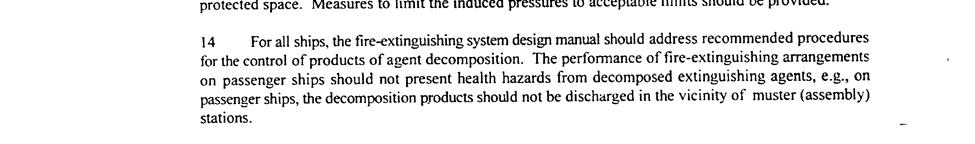
7 1. INTRODUCTION OBJECTIVES... 1 Page 3. TECHNICAL CONSIDERATIONS TEST COMPARTMENT FIRE SCENARIOS EXTINGUISHING SYSTEMS Ansul HEFFSS Buckeye HEFFSS Chemguard HEFFSS FOAM KNOCKDOWN SYSTEM INSTRUMENTATION Machinery Space and Fire Monitoring Instrumentation Air/Gas Temperature Measurements Fire Temperature Measurements Gas Concentration Measurements Fuel System Pressure Measurements Depth Indicators HEFFSS Instrumentation HEFFSS Pressure Measurements HEFFSS Flow Rate Measurements Video Equipment PROCEDURES RESULTS AND DISCUSSION... 2 vii
8 1.1 General Results Problems Determining Extinguishment Times Extinguishment Difficulty Specific Results Ansul HEFFSS Results Buckeye HEFFSS Results Chemguard HEFFSS Results Results Summary Parametrics Evaluation Fill Rate Fire Parameters Fire Type Fuel Type Fire Size Fire Location Foam Generation Using Inside Air System Requirements Test Protocol SOLAS/FSS Requirements Technical Issues/Discussion SUMMARY REFERENCES APPENDIX A - IMO TEST PROTOCOL... A-1 APPENDIX B - TEST DATA... B-1 LIST OF ILLUSTRATIONS viii
9 Page Figure 1. Machinery Space Configuration...4 Figure 2. Diesel Engine Mockup (Section and Plan Views)...5 Figure 3. Fire Locations...6 Figure 4. HEFFSS Schematic...12 Figure 5. Foam Knockdown System...13 Figure 6. Compartment Instrumentation...16 Figure 7. Typical Spray Fire Temperature History...22 ix
10 LIST OF TABLES Page Table 1. Fire Scenarios...7 Table 2. Spray Fire Parameters...8 Table 3. HEFFSS Design Summaries (Manufacturers' Data)...1 Table 4. Ansul Test Results...24 Table 5. Buckeye Test Results...26 Table 6. Chemguard Test Results...27 Table 7. Fill Rate Comparison...31 Table 8. Fuel Type (Diesel versus Heptane) Comparison...31 Table 9. Fire Size Comparison...33 Table 1. Fire Location Comparison...34 Table 11. Comparison of Results Using Inside and Outside Air...35 Table 12. Extinguishment Time Summary (all tests conducted using outside air)...38 x
11 1. INTRODUCTION The United States Coast Guard (USCG) is currently considering the use of High Expansion Foam Fire Suppression Systems (HEFFSS) for protecting shipboard machinery spaces, an application where there is only limited performance data. Although the USCG has never been solicited for a type approval for these systems, there are systems that have received approvals from other Administrations for use in shipboard machinery spaces per the requirements in the document Safety of Life at Sea (SOLAS) [International Maritime Organization, 21a] and based on testing conducted against the two test protocols described in the International Code for Fire Safety Systems (FSS Code) [International Maritime Organization 21b]. (MSC circular 67, Guidelines for the Performance and Testing Criteria and Surveys of High Expansion Form Concentrates for Fixed Fire-Extinguishing Systems, and MSC circular 582, Guidelines for the Performance and Testing Criteria, and Surveys of Low-Expansion Foam Concentrates for Fixed Fire-Extinguishing Systems. ) To assist the USCG in developing a position on the use of HEFFSS in machinery space applications, a series of full-scale fire tests were conducted to define the capabilities and limitations of these systems in this application. The results of this evaluation are presented in this report. 2. OBJECTIVES The objectives of this test program were to define the capabilities and limitations of HEFFSS in shipboard machinery space applications and to assess the adequacy of these systems for this application. 3. TECHNICAL CONSIDERATIONS HEFFSS hardware and fire scenario in MSC/Circ. 67 are not considered representative of the conditions and hazards of a shipboard machinery space MSC/Circ. 67 consists of a 1.73 m 2 heptane pan fire conducted in a 2 m x 2 m x 1 m enclosure. The enclosure is made of wire mesh. A specific size (6.1 Lpm at 5 kpa) high expansion foam generator is used to extinguish the fire during the test. There does not appear to be any correlation between the foam generator used 1
12 during the test and those installed on the ship (the ones installed on the ship should have a significantly greater capacity). In order to successfully complete the test, the fire must be extinguished within 12 seconds of system activation. Since MSC/Circ. 67 is not considered representative of machinery space applications and hazards, the first step was to identify a set of tests in which to evaluate these suppression systems. There are currently three International Maritime Organization (IMO) test protocols for approving other technologies for machinery space applications. These include the standard for approving water-based (mist) systems (MSC circular 668/728), the gaseous agent test protocol (MSC circular 848), and the fixed aerosol test protocol (MSC circular 17). All three protocols are conducted in a full-scale 5 m 3 machinery space containing a simulated diesel engine mockup. A significant effort went into developing these protocols to make them representative of typical machinery space conditions and hazards. After a review of the three MSC circulars, the gaseous agent test protocol (MSC circular 848) was selected to be the basis of this investigation. During the review, the water mist standard (MSC circular 668/728) was eliminated due to the large number of required tests and the test configuration which includes a large vent opening that would allow the foam to flow out of the compartment. The aerosol standard is similar to the gaseous agent standard and was eliminated due to the small size of the test fires. It was believed that the larger fires would present a greater challenge to the HEFFSS. The gaseous agent test protocol consists of four tests. The first test is an agent distribution test conducted against small cup fires located in the corners of the compartment and was not included in this evaluation. The remaining three tests consist of combinations of spray, pan, and wood crib fires allowing an assessment of the HEFFSS capabilities against a range of fires sizes, types, and locations (elevations and degree of obstruction). 4. TEST COMPARTMENT The tests were conducted in a simulated machinery space aboard the test vessel, STATE OF MAINE, at the U.S. Coast Guard Fire and Safety Test Detachment located at Little Sand Island in Mobile, AL. The machinery space was located on the fourth deck of the Number 6 2
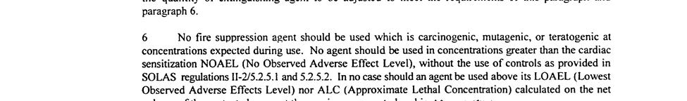
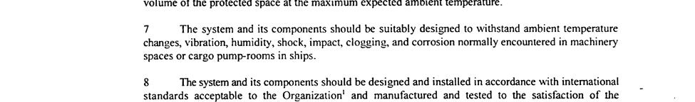
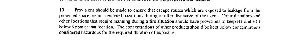
13 cargo hold. The compartment was constructed to meet the dimensional requirements of the IMO test protocol (MSC/Circ. 848). The compartment volume was approximately 5 m 3 with nominal dimensions of 1 m x 1 m x 5 m as shown in figure 1. The diesel engine mockup described in the test protocol was located on the fourth deck in the center of the compartment as shown in figure 2. Air to support combustion was provided naturally through two 2 m 2 vent openings located on the fourth deck forward in the compartment. These two vents were equipped with remotely activated retractable doors. Products of combustion were exhausted from the compartment through a 6 m 2 vertical stack located in the back of the compartment (aft). The exhaust stack was equipped with a remotely activated hydraulic damper. The supply vents (the four doors and the two IMO vents) were open during the preburn period and closed just prior to agent discharge. The vertical stack remained open for the entire test. 5. FIRE SCENARIOS The fire scenarios required by MSC circular 848 are listed in table 1 and are designated using the following numbers: 1, 2A, 2B, 3, and 4. The locations of these fires are shown in figure 3. Halocarbon agents are evaluated against fire Scenarios 1, 2A, 3, and 4, with the inert gases tested against fire Scenarios 1, 2B, 3, and 4. The halocarbon fire tests (1, 2A, 3 and 4) were selected as the basis for this evaluation since they have a higher heat release rate than the fires required for the inert gases. 3
14 Figure 1. Machinery Space Configuration. 4
15 Flowing / Spraying and Concealed oil spray Steel plate ~4 mm Solid steel plate ~5 mm Tray 4 m 2 Steel plate ~2 mm Wall 1 mm gap between engine and inside perimeter of bilge plate Tray 4 m 2 25 mm dia. Reignition rod (All measurements are in mm, unless otherwise noted.) Figure 2. Diesel Engine Mockup (Section and Plan Views). 5
16 Plan View Figure 3. Fire Locations. 6
17 The telltale fire scenario (Scenario 1) was eliminated since it does not apply to this technology. The telltale fire test is intended to define three critical parameters of gaseous agent systems: minimum extinguishment concentration, minimum nozzle pressure and the mixing characteristics of the system. None of these parameters are associated with this technology. As a result, the fire scenarios that served as the basis of this evaluation are shown as the shaded areas on table 1. Table 1. Fire Scenarios. Fire Scenario Nominal Total Components Nominal Heat Location (Figure 3) Heat Release Rate Release Rates 1 ~24 kw 82 cm 2 heptane pan fires ~3 kw/ea Corners (TT) (telltales) 2A 7.95 MW Low pressure heptane spray fire 5.8 MW Top of mockup (S1) High pressure diesel spray fire 1.8 MW Top of mockup (S2).25 m 2 heptane pan fire.35 MW Under mockup (P1) 2B.49 MW.1 m 2 heptane pan fire.14 MW Side of mockup (P2).25 m 2 heptane pan fire.35 MW Under mockup (P1) MW Low flow heptane spray fire 1.1 MW Side of mockup (S3) Wood crib.3 MW Deck level (C1) 2. m 2 diesel pan fire 3. MW Bilge Plate (P3) 4 6. MW 4. m 2 diesel pan fire 6. MW Bilge (P4) Additional fire tests were also conducted to further identify the capabilities and limitations of each system. Evaluations were conducted to determine how specific HEFFSS design parameters and test conditions (e.g., fire scenarios) affect the fire extinguishing capabilities of these systems. This evaluation included an assessment of compartment fill rate, extinguishment difficulty as a function of fire parameters (e.g., fire type, size, fuel and location) and how the use of inside air (products of combustion) affects the capabilities of the system. To reduce the time/cost of testing, each system was assessed against a different parameter/parametric assessment. These parametric assessments were conducted using the most challenging fires listed in table 1. 7
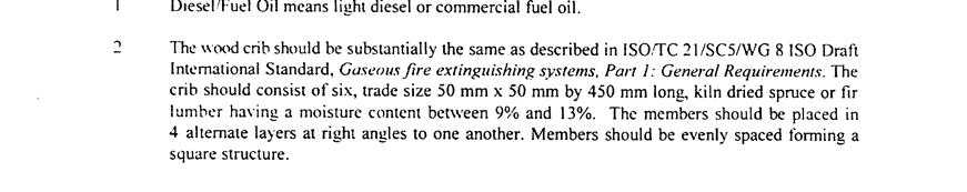
18 The fuel pans used during these tests were square in shape and constructed of 3.2 mm steel plate with welded joints. The pans were 22.9 cm in depth with side dimensions of 31.6 cm, 5 cm, 144 cm, and 2 cm for the.2 m 2,.25 m 2, 2 m 2, and 4 m 2 pans, respectively. These pans were filled with a 2.5 cm deep layer of water and a 5 cm deep layer of either heptane or diesel fuel. Heptane was added to the 2 m 2 and 4 m 2 diesel pans to initiate the fire (1.9 L and 3.8 L respectively). The wood crib used in Fire Scenario 3 consisted of 4 layers of 6 members each. Each member was trade size cm (actual cm) fir lumber with a moisture content between 9 percent and 13 percent. The wood crib was placed on an angle iron frame.3 m above the deck. The crib was ignited using a.25 m 2 pan that was fueled with 3.8 L of heptane. The spray fire parameters are given in table 2. The low-pressure heptane spray fires were produced using a pressurized fuel tank and a pipe network constructed of 1.2 cm diameter stainless steel tubing. The fuel tank was pressurized with nitrogen from a regulated cylinder. The high-pressure diesel spray was produced using a positive displacement pump and a pipe network constructed of 1.2 cm stainless steel tubing. Both systems were remotely actuated using solenoid valves and were equipped with a quarter turn ball valve for safety reasons. Table 2. Spray Fire Parameters. Fire Type Low Pressure Low Pressure, Low Flow High Pressure Heptane Heptane Diesel Spray nozzle Wide spray angle ( ) full cone type Wide spray angle (8 ) full cone type Standard angle (at 6 bar) full cone type Nozzle make and model Bete Fog Nozzle P-12 Bete Fog Nozzle P-48 Spraying Systems LN-8 Fuel flow.16 ±.1 kg/s.3 ±.5 kg/s.5 ±.2 kg/s Fuel temperature 2 ± 5 C 2 ± 5 C 2 ± 5 C Nominal heat release rate 5.8 ±.6 MW 1.1 ±.1 MW 1.8 ±.2 MW 8
19 The fires were ignited to achieve the MSC/Circ. 848 preburn times, prior to foam discharge, of 36 seconds for wood cribs, 12 seconds for pan fires, and 15 seconds for spray fires. In order for a gaseous agent system to successfully complete MSC/Circ. 848, all Class B fires must be extinguished within 3 seconds of the end of agent discharge and the mass loss of the wood crib in Fire Scenario 3 cannot exceed 6 percent of its original weight. This implies that the wood crib must be extinguished during the tests. 6. EXTINGUISHING SYSTEMS The three HEFFSS/manufacturers in this evaluation were Ansul Inc., Buckeye Fire Equipment, and Chemguard Inc. Each manufacturer was responsible for the design of their respective system. These designs were based on the minimum SOLAS/FSS Code requirements plus some additional capacity to provide a factor of safety for these tests. Each system contained two basic parts: a foam concentrate proportioning system and water motor driven foam generator(s). The Ansul and Chemguard systems consisted of two generators, while the Buckeye system consisted of only one. The generator(s) were installed either in the overhead of the space or high at the aft end of the port bulkhead. These locations were shown in figure 1. The HEFFSS designs are described in subsequent sections of this report and are summarized in table Ansul HEFFSS The Ansul HEFFSS consisted of two 16 m 3 /min foam generators (Model Number Jet-X-2A) installed high at the aft end of the port bulkhead and in the overhead of the space. Each generator was designed to discharge a 2.75 percent solution of Jet-X foam concentrate with an expansion ratio of about 545:1. The foam concentrate was proportioned using a proportioner (Model Number 71894) connected to an Ansul 19 l bladder tank (Part Number 751/752). 9
20 Table 3. HEFFSS Design Summaries (Manufacturers Data). Manufacturer Manufacturer Manufacturer Name Ansul Buckeye Chemguard 1 Foam Concentrate Potential Expansion Ratios 5:1 to 1:1 up to 1:1 up to 1:1 Proportioning Concentration 2.75% 2.2% 2% Flow Rate (Lpm) 6.9/ /9.6 Model Name / Number Jet-X-2A BF-HIEX-5 3WP Part Number 421 FG-5 M Vol. Flow Rate (m 3 /min) 16/ /226 Foam Generator Expansion Ratio 545:1 5:1 475:1 Foam Solution Flow Rate (Lpm) 25/ /48 Solution Pressure (kpa) Power Source Water Water Water Mounting Orientation Bulkhead & Overhead Overhead Bulkhead & Overhead Model / Part Number * EF1322 Proportioning Device Type Proportioner Proportioner Proportioner Size (in.) Type Bladder Bladder Bladder Tank Model / Part Number 751/ / /752 Orientation Vertical Vertical Vertical Capacity (L) Supply Air Source Outside Outside Inside & Outside * Used Ansul proportioner during testing
21 The proportioning system was located outside the space on the 2 nd Deck. Each generator was designed to discharge 25 Lpm of foam solution (water and foam concentrate) at a pressure of 7 kpa, which corresponded to a concentrate flow rate of 6.9 Lpm. A number of tests were also run in which the operating pressure of the generators was lowered to 3 kpa. A schematic of the system is shown in figure Buckeye HEFFSS The Buckeye HEFFSS consisted of a single 142 m 3 /min foam generator (Model Number: BF-Hiex-5) located in the overhead of the space. The generator was designed to discharge a 2.2 percent solution of Buckeye Hi-Ex concentrate with an expansion ratio of about 5:1. The concentrate was proportioned using the Ansul proportioning set-up from the previous tests. The system was designed to discharge 473 Lpm at a pressure of 6 kpa, which corresponded to a concentrate flow rate of 1.4 Lpm. A schematic of the system is shown in figure Chemguard HEFFSS The Chemguard HEFFSS consisted of two 113 m 3 /min foam generators (Model Number 3 WP) installed high at the aft end of the port bulkhead and in the overhead of the space. Each generator was designed to discharge a 2 percent solution of Chemguard C2S Foam concentrate with an expansion ratio of about 475:1. The concentrate was proportioned using a Chemguard proportioner (Model Number EF1322). The system was designed to discharge 24 Lpm at a pressure of 56 kpa, which corresponds to a concentrate flow rate of 4.8 Lpm. A schematic of the system is shown in figure FOAM KNOCKDOWN SYSTEM In order to expedite foam removal after each test, a foam knockdown system was installed in the overhead of the space. The knockdown system consisted of a three by three grid of Bete TF nozzles installed in the overhead of the space with a nominal 3. m nozzle spacing as shown in figure 5. The system was designed to discharge 34 Lpm of solution at an operating pressure of 28 kpa. The solution contained 9 percent water (Mobile bay water) and 11
22 Figure 4. HEFFSS Schematic. 12
23 Figure 5. Foam Knockdown System. 13
24 1 percent defoaming agent (D-Foaming ST manufactured be SELIG Industries). The defoaming agent was injected into the water stream using the proportioning system also shown in figure 5. Prior to testing, there were some concerns regarding the effect that residual defoaming agent may have on the development and buildup of foam in subsequent tests. This was shown not to be the case during a series of cold discharge tests conducted prior to using the defoaming agent. During the initial week, the foam was knocked down using only water from the overhead system. During the second and third weeks of testing, the foam was more robust requiring the use of the defoaming agent. 8. INSTRUMENTATION Both the test compartment and the HEFFSS were instrumented for these tests. The instruments installed in the test compartment monitored both the thermal conditions in the space and the status of each fire during the test. The HEFFSS instrumentation was used to monitor the discharge characteristics of the system (flow rate and pressure). The U.S. Coast Guard s data acquisition system was used to collect all data at a rate of 1 scan per second. The instrumentation scheme is shown in figure Machinery Space and Fire Monitoring Instrumentation The machinery space was instrumented to measure air temperatures; fire/flame temperature (to note extinguishment time); fuel system pressure; and O 2, CO 2, and CO gas concentrations. A more detailed description of these instruments is listed as follows Air/Gas Temperature Measurements One thermocouple tree was installed in the center of the compartment. The tree consisted of nine thermocouples positioned at the following heights above the lower deck (.5, 1., 1.5, 2., 2.5, 3., 3.5, 4., and 4.5 m). Inconel-sheathed, Type K thermocouples (.32 cm diameter Omega Model KMQIN-125G-6) were used for this application. 14
25 15
26 Figure 6. Compartment Instrumentation. 16
27 8.1.2 Fire Temperature Measurements To aid in the determination of extinguishment time, each fire was instrumented for temperature. One thermocouple per fire was placed inside the wood crib in the flame region, 2 cm above the pan fires, and 45 cm downstream of the spray fire nozzles. Inconel-sheathed, Type K thermocouples (.32 cm diameter Omega Model - KMQIN-125G-6) were used for this application. Additional thermocouples were added at the end of the first week of testing to further aid with the determination of extinguishment time Gas Concentration Measurements Carbon monoxide, carbon dioxide, and oxygen concentrations were sampled in the center of the compartment at three elevations 1., 2.5 and 4.5 m above the deck as shown in figure 6. MSA Lira 3 Analyzers with a full-scale range of 1 percent by volume were used to measure the carbon monoxide concentration. MSA Lira 33 Analyzers with a full-scale range of 25 percent by volume were used to monitor the carbon dioxide concentration. Rosemont 755 Analyzers were used to monitor the oxygen concentration with full-scale range of 25 percent by volume. The gas samples were pulled through.95 cm stainless steel tubing and a Drierite packed filter using a vacuum sampling pump at a flowrate of 1 Lpm, resulting in a transport delay on the order of 1-2 seconds Fuel System Pressure Measurements The fuel nozzle pressure for the spray fires was monitored approximately six meters upstream of the nozzles where the fuel line enters the test chamber. The two low-pressure spray fires were monitored using a Setra Model 25-2 pressure transducer with a full-scale range of 1.7 MPa. The high-pressure spray fire was monitored using a Setra Model 25-2 pressure transducer with a full-scale range of 2.7 MPa. 17
28 8.1.5 Depth Indicators Foam depth indicators were installed in each quadrant of the space. These depth indicators were monitored manually during the cold agent discharge test(s). The depth indicators consisted of a pole running the height of the compartment with markings every.5 meters (.5, 1., 1.5, 2., 2.5, 3., 3.5, 4., 4.5 m). During the initial test of each system (cold discharge test), the fill rate and expansion ratio of the system were determined by averaging the results of the four height measurements as a function of time. 8.2 HEFFSS Instrumentation The HEFFSS was instrumented to measure the system operating pressure and flow rate during the test. Both the total solution and concentrate volumetric flow rates were measured. A more detailed description of these instruments is listed as follows HEFFSS Pressure Measurements System pressures were measured at the inlets to the foam-proportioning device and the high expansion foam generator(s). Setra Model 25-2 pressure transducers were used for this application. These transducers have a range of -175 kpa with an accuracy of.1 percent fullscale HEFFSS Flow Rate Measurements For each system, the volumetric flow rate of the foam solution was measured at the inlet to the high expansion foam generator(s). This measurement was used in conjunction with the measured fill rate to calculate the volumetric expansion ratio of the foam solution. The total solution flow rate was measured using a Flow Technologies Inc. paddle wheel flow meter with a full-scale range of -15 Lpm and an accuracy of 1. percent of the measured value. The foam concentrate flow rate was measured using a Hoffer Inc. flow meter (Model H1/4-135) with a range full-scale of Lpm and an accuracy of 1 percent of the measured value. For the Chemguard system, it was not possible to measure the concentrate flow rate using this device because the higher viscosity of the foam concentrate prevented the flow 18
29 meter from functioning correctly. As a result, the concentrate flow rate of the Chemguard system was determined based on the amount of concentrate consumed during each test and the duration of the discharge. In all cases, the solution concentration was estimated based on the solution and concentrate flow rate measurements. 8.3 Video Equipment Five video cameras were used to visually document the events of the tests. Two video cameras were located inside the compartment adjacent to the fire locations (scenario specific locations). The other three cameras were located outside the compartment primarily viewing the area around the diesel engine mockup. A microphone was also installed in the center of the space to provide the audio for the five video cameras. 9. PROCEDURES The tests were initiated from the control room located on the second deck level forward of the test compartment. Prior to the start of the test, the pans were fueled, and the compartment ventilation condition was set. The two 2 m 2 lower vents and the 6 m 2 stack vent were opened prior to the start of the test. The video and data acquisition systems were activated, marking the beginning of the test. One minute after the start of the data acquisition system, the fires were ignited, and the compartment was cleared of test personnel. The preburn times of the fires in the tests defined the ignition sequence timing. Wood crib fires were ignited 36 seconds prior to systems activation. Pan fires were ignited 12 seconds prior to systems activation. Spray fires were ignited 15 seconds prior to systems activation. Ten seconds prior to foam discharge, the two lower vents into the space were closed and HEFFSS was activated. The large stack damper remained open for the duration of the test to prevent the oxygen depletion in the compartment from extinguishing the test fires. [The fuel for the spray fires was secured shortly after the fire was thought to be extinguished due to a decrease in temperature measured by the fire thermocouples and the lack of visible flames.] The test continued for ten minutes after HEFFSS activation or until all of the fires had been extinguished. On completion of the test, the overhead foam knockdown system was activated to prepare the space for the next test. Once the foam was sufficiently reduced below the ventilation openings, the space was ventilated in preparation for the next test. 19
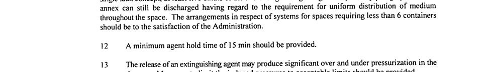
30 1. RESULTS AND DISCUSSION 1.1 General Results A total of 35 tests were conducted during this evaluation. These 35 tests consisted of 14 tests using the Ansul system, 11 tests using the Buckeye system and 1 tests using the Chemguard system. In addition to the four tests required by MSC circular 848, a parametric study was conducted with each system (different parameters were evaluated for each system). These parameters included fill rate, expansion ratio, and extinguishment difficulty as a function of fire type, size and location. The parameters also included how the use of inside (dirty air/vitiated gasses) affects the fire extinguishing capabilities of the system. The results of these tests are discussed in the following sections. The data recorded during each test are provided in Appendix B. These measurements include the temperature and oxygen profiles/histories in the compartment, the thermocouples installed in the flames, and the discharge characteristics of the system (pressures and flow rates) Problems Determining Extinguishment Times At times, it was difficult to confirm that the fire was extinguished using either visual observations or instrumentation. This was especially true for the spray fires. As the foam engulfed the spray fire, there were times where no flames were visible in the compartment. The foam blanket was calm and there was no indication of any fire beneath. After a few seconds, a flame would burst from the foam blanket and continuously burn in the compartment. Over time, this flame/jet would be covered again by the foam, and the cycle would repeat. These conditions were only visible for the short period of time before the compartment was completely full of foam. As a result of this difficulty in using visual observations to determine extinguishment, a greater emphasis was placed on using the thermocouples installed in the space to monitor the status of the fire. As will be discussed in the following paragraphs, using these temperatures to determine extinguishing time was also somewhat problematic. 2
31 Figure 7 is a plot of the temperatures measured by the thermocouples installed in and around the fire in Ansul Test #5. At two and a half minutes into the test, the fire appeared to be extinguished (no visible flames, no motion/bubbling of the foam blanket and all of the thermocouples where rapidly approaching ambient temperatures). Approximately three and a half minutes later, the fuel to the spray fire was secured. Immediately after the fuel was secured, the temperatures near the fuel nozzle dropped only 35 ºC. This indicated that there were still flames somewhere in the compartment when the fuel was secured. It is believed that the fire may move away from the fuel source and burn in void/air pockets in the foam. A short period of time later, flames were also observed in the compartment (orange flashes were observed on the video being recorded inside of the space). To address possible displacement of the flames by the foam, additional thermocouples were placed around each fire between the first and second weeks of testing. Securing the fuel spray was also delayed for at least one minute after the fire appeared to be extinguished. Even with these additional precautions, there were still a limited number of tests where the fuel was secured prior to the fire being completely extinguished Extinguishment Difficulty Consistent with the literature (Ingason, 1992), the pan fires were easily extinguished and spray fires presented a major challenge to the HEFFSS. Independent of the system tested (foam type, hardware, fill rate, etc.), when the foam reached the height of the pan fires, the foam quickly flowed across the fuel surface and the fire was extinguished. The spray fires on the other hand were much more difficult to extinguish. In some instances, the spray fires were never 21
32 1 8 Fire Temperature ( C) 6 4 TC Indicates Extinguishment No Visible Flames in Space Fuel Spray Secured Visual Flame Observed Shortly After Fuel Spray Was Secured Time (Seconds) Figure 7. Typical Spray Fire Temperature History. 22
33 extinguished. The majority of the spray fires that were extinguished required foam depths of 2-5 meters above the height of the fire location. Many times, the spray fires were not extinguished until the machinery space was completely filled with foam and the foam was pushed out of the vents of the compartment. This raises the question to whether HEFFSS can adequately protect extremely large machinery spaces. The difficulty extinguishing the spray fires was observed early into the first week of testing. To increase the likelihood of success for the remaining tests, it was decided to abandon the SOLAS/FSS fill rate of 1 m/min and use the maximum rate obtainable with the equipment at hand. 1.2 Specific Results Ansul HEFFSS Results Fourteen tests were conducted with the Ansul HEFFSS. The fourteen tests included two cold discharge tests, six tests conducted against the fire scenarios required by MSC circular 848 and six spray fire tests. The spray fire tests were added to the Ansul test series (not in the test plan) due to difficulties observed extinguishing these fires during the first couple of tests. The results of these tests are summarized in table 4. To allow the flexibility of increasing the fill rate during the test series, Ansul provided two Jet-X-2A generators. During the first fire test, (Test 3 Scenario 3), the single generator system failed to extinguish the 1.1 MW heptane spray fire on the side of the mockup. To increase the likelihood for success during the remaining tests, the higher fill rate/two generator system was used with the Ansul system. For the two generator system, one of the generators was installed in the bulkhead and the other in the overhead of the space. The system was operated at approximately 7 kpa for a majority of the tests. During the fill rate parametric assessment, a limited number of tests were also conducted with an operating pressure of 35 kpa. At the higher operating pressure (7 kpa), the system produced foam with an expansion ratio of about 32:1 and a fill rate 23
34 Table 4. Ansul Test Results. Test Number Fire Scenario Individual Fires System Pressure Fill Rate Expansion Ratio Extinguishment Time [kpa] [m/min] [sec] 1* Cold Discharge :1 2 Cold Discharge :1 2 m 2 Diesel Pan 59 3* Scenario 3 Wood Crib : MW Heptane Spray 35 4 Heptane Spray on Side 1.1 MW Heptane Spray : Heptane Spray on Side 1.1 MW Heptane Spray :1 No Ext 2 m 2 Diesel Pan 2 6 Scenario 3 Wood Crib : MW Heptane Spray No Ext.25 m 2 Heptane Pan 65 7 Scenario 2A 1.8 MW Diesel Spray : MW Heptane Spray m 2 Heptane Spray 55 8 Scenario 2A 1.8 MW Diesel Pan : MW Heptane Spray m 2 Heptane Pan 6 9 Scenario 2A 1.8 MW Diesel Spray :1 No Ext 5.8 MW Heptane Spray No Ext 1 Scenario 4-4 m 2 Diesel Pan : Sprays - Deck Level 1.8 MW Diesel Spray :1 5.8 MW Heptane Spray Sprays - Deck Level 1.8 MW Diesel Spray :1 5.8 MW Heptane Spray Heptane Spray on Side 1.1 MW Heptane Spray :1 No Ext 14 Heptane Spray on Side 1.1 MW Heptane Spray :1 No Ext * Tests conducted with a single foam generator No Ext = No extinguishment 24
35 of 1.6 m/min. The lower pressure resulted in a reduced fill rate (1.4 versus 1.6) but the expansion ratios remained relatively the same. The Ansul HEFFSS was evaluated during the first week of full-scale testing. As stated in Section 1.1.1, it was difficult to determine when the spray fires had been extinguished. As a result, some of the tests conducted with the Ansul system were stopped prematurely (the fuel was secured prior to the fire being extinguished and/or before the end of the ten minute of discharge period). These tests are indicated in table 4. To summarize the results, the two-generator Ansul system quickly extinguished the pan fires (Tests 3, 6, and 1) but could not consistently extinguish the spray fires. The system was capable of extinguishing spray fires located low in the space (Tests 11 and 12) but only extinguished two (Test 8) of the twelve spray fires located above deck level (on the side or on the top of the mockup) Buckeye HEFFSS Results The Buckeye HEFFSS consists of a single generator installed in the overhead of the space. The system was operated at approximately 6 kpa producing foam with an expansion ratio of about 3:l and a fill rate of 1.7 m/min. Eleven tests were conducted with the Buckeye HEFFSS. These tests include two cold discharge tests, the three tests required by MSC circular 848, and six tests conducted against spray fires (parametric assessment). The results of the tests are summarized in table 5. The Buckeye HEFFSS was capable of extinguishing all of the fires conducted during this evaluation. Consistent with the previous tests, the spray fires presented the greatest challenge requiring in some cases over seven minutes to extinguish (Tests 4 and 11). The results of the spray fire parametric study will be discussed later in this report. 25
36 Table 5. Buckeye Test Results. Test Number Fire Scenario Individual Fires System Pressure Fill Rate Expansion Ratio Extinguishment Time [kpa] [m/min] [sec] 1 Cold Discharge :1 2 Cold Discharge :1 3 Scenario 4 4 m 2 Diesel Pan : m 2 Diesel Pan : Scenario 3 Wood Crib MW Heptane Spray 43 5 Vertical Diesel Spray - Deck Level 1.8 MW Diesel Spray : Horizontal Heptane Spray - Deck Level 5.8 MW Heptane Spray : Horizontal Heptane Spray - Deck Level 2 MW Heptane Spray : Vertical Diesel Spray - Top of Mockup 1.8 MW Diesel Spray : Horizontal Heptane Spray - Top of Mockup 2 MW Heptane Spray : Horizontal Heptane Spray - Top of Mockup 5.8 MW Heptane Spray : m 2 Heptane Pan : Scenario 2A 1.8 MW Diesel Spray MW Heptane Spray Chemguard HEFFSS Results The Chemguard HEFFSS consisted of two (2) model 3 WP foam generators. When tested with inside air, the two generators were installed side-by-side high in the space. When tested with outside air, one generator was installed in the bulkhead and the other one in the overhead of the space. The system was operated at approximately 4 kpa. When clean outside air was used to make the foam, the foam expansion ratio was approximately 25:1 resulting in a fill rate of 1.5 m/min. These parameters were dramatically reduced when the products of combustion were used to make the foam (25:1 versus 3:1). 26
37 Ten tests were conducted with the Chemguard HEFFSS. Five tests were conducted with inside air (Tests 1-5) and five tests were conducted with outside air (Tests 6-1). The results of the tests are summarized in table 6. Table 6. Chemguard Test Results. Test Number Fire Scenario Individual Fires System Pressure Source of Air Fill Rate Expansion Ratio Total Foam Flow Time Extinguishment Time [kpa] [m/min] [sec] [sec] 1 Scenario 4 4 m 2 Diesel Pan 4 Inside.15 3: Cold Discharge 35 Inside :1 3 3 Scenario 4 4 m 2 Diesel Pan 4 Inside.15 3: Scenario 3 Horizontal Heptane Spray - Deck Level 2 m 2 Diesel Pan 45 Wood Crib 4 Inside.15 3: MW Heptane Spray Inside.15 3:1 41 No Ext 5.8 MW Heptane Spray 6 Cold Discharge 31 Outside : m 2 Diesel Pan 95 7 Scenario 3 Wood Crib 4 Outside : MW Heptane Spray Scenario 4 4 m 2 Diesel Pan 4 Outside : Horizontal Heptane Spray - Deck Level 5.8 MW Heptane Spray 39 Outside : m 2 Heptane Pan 3 1 Scenario 2A 1.8 MW Heptane Spray 375 Outside : MW Diesel Spray 245 The initial tests conducted with the system were run using inside air. During these tests, the hot and smokey gases were observed to significantly impact the system s ability to make foam. During the tests conducted with diesel fuel (namely Scenario 4), the foam produced by the system was very wet (low expansion ratio) and was observed to have the consistency of foam shaving cream (i.e., somewhat stiff). During the tests conducted with the larger fires that produced higher gas temperatures in the upper layer, the foam was very light and dry. In either case, both the fill rate and expansion ratio of the foam were significantly reduced by the use of inside air. 27
38 HEFFSS that use inside air are only capable of filling the compartment with foam to the height of the generator. As a result, MSC/Circ. 848 Scenario 2A was modified for the test conducted using the Chemguard HEFFSS with inside air. The modification consisted of moving the two large spray fires on top of the mockup (located above the generator) to deck level. During the tests conducted with inside air, the Chemguard HEFFSS was capable of extinguishing two of the three fire scenarios required by MSC/Circ. 848 (Scenario 3 and 4). The Chemguard HEFFSS using inside air could not extinguish the large spray fire combination in Scenario 2A. The extinguishment times for the system using inside air were significantly longer than those observed for the system using outside air. The Chemguard HEFFSS using outside air was capable of extinguishing all of the test fires in about four minutes or less Results Summary A total of 35 tests were conducted in this evaluation utilizing the equipment and concentrates from three manufacturers: Ansul, Buckeye and Chemguard. All of the systems produced foams with observed expansion ratios on the order of 3:1. This is much lower than published/advertised values (3:1 versus 5:1) of the manufacturers. The difference may be associated with how the expansion ratio is determined. During these tests, the expansion ratio was determined based on filling a compartment. The manufacturers data may be based on the foam as it exits the generator (unknown). Also, the use of brackish water (Mobile Bay water) during these tests may have also contributed to the lower expansion ratio. The average system fill rate during these tests was on the order of 1.6 m/min. All three systems easily extinguished the pan fires included in this evaluation independent of the fuel type (heptane or diesel). The differences in system capabilities were observed during the extinguishment of the spray fires (namely, the heptane spray fires). The heptane spray fires presented a major challenge to the HEFFSS. During the tests conducted with the heptane spray fires, the extinguishment times were in many cases, two to three times longer than it took to fill the compartment with foam during the cold discharge tests. Although the heptane spray fire was consuming some of the foam, a significant amount was observed flowing out of all of the openings in the compartment by the end of the test. Under certain conditions 28
39 (spray fire size, location/elevation and agent/system), there appears to be the need to compress the foam (making it denser and/or wetter at the fire location) in order to extinguish the heptane spray fires. There were variations in the fire suppression capabilities (and foam quality) between the three manufacturers. The Buckeye and Chemguard systems produced more robust foam (i.e., hard to break down) and were both capable of extinguishing the heptane spray fires. The foam produced by these two systems was so robust, the space needed to be cleaned using a defoaming agent after each test. The Ansul foam was more fragile and had difficulty extinguishing the heptane spray fires. During cleanup, the Ansul foam was quickly broken down/washed away using short bursts of water. It is unknown whether the difficulty extinguishing the heptane spray fires was associated with the foam concentrate, foam generating equipment or both. The results of these tests demonstrate the potential for using HEFFSS for protecting shipboard machinery spaces. However, most of the high expansion foam systems were developed and tested many years ago. Due to the niche market (namely aircraft hangars) there is only limited data defining the capabilities of these systems. In fact, when conducting the literature search, there was only one report (Ingason, 1992) that was applicable to this application. With the potential to become a Halon/CO 2 alternative in the maritime industry, the current manufacturers may be interested in pursuing additional development/optimization of there respective systems/technologies. 1.3 Parametrics Evaluation An evaluation was conducted to determine how specific HEFFSS design parameters and test conditions (e.g., fire scenarios) affect the fire extinguishing capabilities of these systems. This evaluation included an assessment of compartment fill rate, extinguishment difficulty as a function of fire parameters (e.g., fire type, size, fuel and location) and how the use of inside air (products of combustions) affects the capabilities of the system. 29
40 1.3.1 Fill Rate Increasing the fill rate has two effects on the fire extinguishing capabilities of the system. First, the foam reaches the fire and starts the extinguishment process sooner and second, the foam surrounds and advances toward the fire faster. This is important when considering that the radiation from the fire tends to breakdown the foam as it approaches. As a result, the higher fill rates tend to overwhelm the breakdown due to radiation, translating into faster extinguishment times and increased capabilities against larger fires. This is demonstrated in the comparisons shown in table 7. As shown in table 7, higher fill rates translate into faster extinguishment times and the need for less foam to extinguish the fire (the amount of foam discharged into the space at the time the fires were extinguished was less for the higher fill rate systems). Based on these results, the minimum fill rate of 1 m/min stated in SOLAS/FSS Code should be significantly increased. This will be discussed in detail in section 1.4 of this report Fire Parameters The fire parameters include fire type (spray or pan fire), fuel type, fire size and fire location. These parameters will be discussed in the following sections of this report Fire Type Consistent with the literature, the pan fires were easily extinguished and the spray fires presented a major challenge to the HEFFSS. Independent of the system tested (foam type, hardware, fill rate, etc.), when the foam reached the height of the pan fires, the foam quickly flowed across the fuel surface and the fire was extinguished. The spray fires on the other hand were much more challenging and, in some cases, never extinguished. 3
41 Table 7. Fill Rate Comparison. 31 System Pressure Fill Rate Enclosure Fill Time Test Fire Scenario [kpa] [m/min] [min] Individual Fires ANSUL 3 Scenario ANSUL 6 Scenario Single Generator Tests 1.1 MW Heptane Spray Two Generator -Reduced Pressure Tests Extinguishment Time Total Foam Required [sec] [m 3 ] 2 m 2 Diesel Pan Wood Crib MW Heptane No Ext Spray 2 m 2 Diesel Pan 2 53 Wood Crib No Ext ANSUL 12 2 Sprays - Deck Level MW Diesel Spray MW Heptane Spray Two Generator -Full Pressure Tests ANSUL 11 2 Sprays - Deck Level MW Diesel Spray MW Heptane Spray
42 It should be noted that going into these tests, even the manufacturers were uncertain of the capabilities of these systems against spray fires. The extinguishment of the spray fires typically occurred when foam depth was 2-5 meters above the height of the fire. Many times the spray fires were not extinguished until the machinery space was completely filled with foam and foam began to be pushed out of the openings of the compartment Fuel Type There was no difference in the extinguishment difficulty of the diesel and heptane pan fires. However, the heptane spray fires were more difficult to extinguish than those produced with diesel fuel. This is assumed to be a function of the flashpoint of the fuel (heptane 4 C, diesel >54 C). As shown in table 8, the diesel spray fires (Tests 5 and 8) were extinguished much faster than the heptane spray fires (Tests 7 and 9). During the diesel spray fire tests, the fire was quickly extinguished shortly after the foam reached the base of the fire. The heptane spray fires on the other hand would continue burning even after they were completely submerged beneath the foam blanket. As a result, the extinguishment times for the heptane spray fires were approximately two times longer than the diesel spray fires. An uninvestigated variable that may have contributed to this behavior is the operating pressure of the fuel spray system. The high pressure diesel spray (1.4 Mpa) caused the actual combustion of the fuel to occur well above the nozzle, reducing the radiant exposure near the nozzle location. The lower pressure heptane spray fire (584 kpa) had the flames closer to the nozzle producing higher radiant exposures (and foam breakdown) near the nozzle. Table 8. Fuel type (Diesel versus Heptane) Comparison. Extinguishment Time Test Fire Scenario Fire Description [sec] Buckeye 5 Vertical Diesel Spray - Deck Level 1.8 MW Diesel 42 Buckeye 7 Horizontal Heptane Spray - Deck Level 2 MW Heptane 87 Buckeye 8 Vertical Diesel Spray - Top of Mockup 1.8 MW Diesel 14 Buckeye 9 Horizontal Heptane Spray - Top of Mockup 2 MW Heptane 33 32
43 Fire Size During this evaluation, the larger spray fires resulted in longer extinguishment times. This is shown in table 9. Table 9. Fire Size Comparison. Test Fire Scenario Fire Description Buckeye 7 Horizontal Heptane Spray - Deck Level Buckeye 6 Horizontal Heptane Spray - Deck Level Buckeye 9 Horizontal Heptane Spray - Top of Mockup Buckeye 1 Horizontal Heptane Spray - Top of Mockup Extinguishment Time [sec] 2 MW Heptane Spray MW Heptane Spray 37 2 MW Heptane Spray MW Heptane Spray 37 As stated previously, the larger fires break down the foam due to the heat build up in the compartment and increased radiant exposure around the base of the fire. Theoretically, there should be a critical fire size for each fill rate where the radiant breakdown of the foam is equal to the rate in which the form advances on the fire. This needs to be further investigated to fully understand the capabilities and limitations of these systems. Breakdown of foam due to hot metal surfaces (radiant exposures and contact with hot metal surfaces) should also be investigated Fire Location A comparison of the extinguishing performance relative to the height of the fire above the deck is provided in table 1. As can be seen from this table, most of the tests have the expected trend that the increased elevation both delays the time required for the foam to reach the fire and makes the fires harder to extinguish since the foam on top of the blanket is drier and more fragile. Intuitively, the lower foam is wetter due to drainage from the foam above. 33
44 Table 1. Fire Location Comparison. Extinguishment Time From Foam Start From Foam Arrival Test Fire Scenario Individual Fires [sec] [sec] Deck Level Ansul MW Diesel Spray Sprays - Deck Level 5.8 MW Heptane Spray Buckeye 5 Vertical Diesel Spray Deck Level 1.8 MW Diesel Buckeye 7 Horizontal Heptane Spray - Deck Level Buckeye 6 Horizontal Heptane Spray - Deck Level Ansul 9 Buckeye 8 Scenario 2A Vertical Diesel Spray - Top of Mockup 2 MW Heptane Spray 5.8 MW Heptane Spray Top of Mockup m 2 Heptane Pan MW Diesel Spray No Ext No Ext 5.8 MW Heptane Spray No Ext No Ext 1.8 MW Diesel Spray Buckeye 9 Horizontal Heptane Spray - Top of Mockup 2 MW Heptane Spray Buckeye 1 Horizontal Heptane Spray - Top of Mockup 5.8 MW Heptane Spray The larger heptane spray fires deviated from this trend by producing faster extinguishment times on top of the mockup than at deck level (relative to foam arrival). The closeness of the fire to the top of the compartment (e.g., the fire was located in the hot gas layer containing reduced oxygen concentration) may have resulted in this deviation (the lower oxygen concentrations may have made these fires less stable) Foam Generation Using Inside Air During these tests, using the products of combustion (inside air) to produce the foam significantly reduced the capabilities of the system. The degradation in capabilities is shown in the results presented in table
45 Table 11. Comparison of Results Using Inside and Outside Air. Extinguishment Time Test Fire Scenario Individual Fires [sec] Inside Air Chemguard 3 Scenario 4 4 m 2 Diesel Pan 65 Chemguard 4 Scenario 3 2 m 2 Diesel Pan 45 Wood Crib MW Heptane Spray 63 Chemguard 5 Horizontal Heptane Spray - Deck Level 5.8 MW Heptane Spray No Ext Outside Air Chemguard 8 Scenario 4 4 m 2 Diesel Pan 35 Chemguard 7 Scenario 3 Chemguard 9 Horizontal Heptane Spray - Deck Level 2 m 2 Diesel Pan 95 Wood Crib MW Heptane Spray MW Heptane Spray 25 The initial tests were conducted using inside air (products of combustion). The hot smokey gases were observed to significantly impact the system s ability to make foam. During the tests conducted with diesel fuel (namely Scenario 4), the foam had the consistency of foam shaving cream. During the tests conducted with the larger fires (and consequently higher gas temperatures), the foam was very light and dry. In both cases, the fill rate and expansion ratio was significantly reduced. During the cold discharge test, the system produced foam with an expansion ratio on the order of 25:1 and filled the compartment at a rate of 1.5 m/min. During the test conducted with inside air against Scenario 4, these quantities, were reduced by almost an order of magnitude (fill rate =.15 m/min and expansion ratio = 3:1). During this evaluation, the Chemguard HEFFSS was tested against the three fire scenarios required in MSC/Circ. 848 (using both inside and outside air). Since the fires in Scenario 2A were the same height in the compartment as the foam generators (and using inside air prevents the generators from filling the box with foam above the height the generators are installed), the large 5.8 MW heptane spray fire in Scenario 2A was moved to deck level. For comparison purposes, the Chemguard HEFFSS using outside air was capable of extinguishing all of the test fires in about four minutes or less. 35
46 During the tests conducted with inside air, the Chemguard HEFFSS was only capable of extinguishing two of the three fire scenarios required by MCS circ. 848 (Scenario 3 and 4). The Chemguard HEFFSS using inside air could not extinguish the large spray fire combination in Scenario 2A. The extinguishment times for these fires was about twice as long as those observed when the system was tested using outside air. 1.4 System Requirements There are two IMO test protocols applicable to HEFFSS in commercial ship machinery space applications. These protocols include a fire test described in MSC circ. 67 and a chemical compatibility test (compatibility with salt water) in MSC circ Although the requirements of MSC/Circ. 582 may apply, the test setup, HEFFSS hardware and fire scenario in (MSC/Circ. 67) are not in any way representative of the conditions and hazards of a shipboard machinery space. There are currently two design constraints placed on HEFFSS in Chapter 6 of the FSS Code. These include a minimum fill rate of 1 meter per minute and a maximum expansion ratio of 1:1. There appears to be no technical justification for these requirements. A detailed discussion of these issues is provided in the following sections Test Protocol Since the current test protocol (MSC/Circ. 67) is not representative of machinery space applications and hazards, the gaseous agent protocol (MSC/Circ. 848) was selected as the basis for this evaluation. The gaseous agent test protocol (MSC/Circ. 848) consists of four tests. The first test is an agent distribution test conducted against small fires located in the corners of the compartment and was not conducted during this evaluation. The remaining three tests consist of combinations of spray, pan and wood crib fires allowing an assessment of the HEFFSS against a range of fire sizes, types, and locations (elevations and degrees of obstruction) all representative of typical machinery space hazards. Based on the results of these tests, parameters of MSC/Circ
47 appear to provide sufficient challenge and range to adequately test HEFFSS for machinery space applications. The difficulty observed in extinguishing spray fires and conversely, the ease in extinguishing the pan fires, demonstrates that the current high expansion foam test protocol (MSC/Circ. 67) is inadequate for approving HEFFSS for machinery space applications. The single pan fire test required in MSC/Circ. 67 does not pose a challenge to HEFFSS. The primary hazard associated with machinery space applications (spray fires) is not even addressed by the protocol. As a result, it is recommended that HEFFSS be approved using the fire tests described in MSC/Circ. 848 rather than MSC/Circ. 67. When adapting MSC/Circ. 848 for use with HEFFSS, some of the test parameters will need to be revised/modified to account for the differences (namely discharge times) between high expansion foam and gaseous agent technologies. These differences need to be reflected in both the fill time and extinguishment time requirements of the system. The minimum fill rate requirement of 1 m/min stated in SOLAS/FSS Code needs to be abandoned for a new approach since it does not insure an acceptable level of performance and does not properly address spaces with vastly different ceiling heights. It also does not account for variations in extinguishing capabilities between HEFFSS. A maximum fill time is a better approach to this requirement and is the approach used in NFPA 11A (1999). Consistent with NFPA 11A, a two minute maximum fill time is recommended for this application (NFPA 11A requires a two minute fill time for unprotected steel compartments containing low flashpoint fuels). This is also the maximum discharge time allowed under MSC/Circ. 848 for inert gas extinguishing systems (if the intent is to keep things somewhat consistent between technologies). A five-minute extinguishment time requirement (five minutes after the start discharge) is also recommended for these systems. This is longer than the gaseous agent system requirements (fires are required to be extinguished within 3 seconds after the end of discharge) but less than the 15 minutes requirement placed on water mist systems in MSC/Circ. 668/728. Based on the results of these tests, the five-minute requirement is challenging and will allow the distinction between higher and lower performance systems. The five-minute extinguishment time 37
48 requirement is acceptable from an exposure standpoint since the fill time requirement of two minutes will quickly reduce the overall exposures in the compartment regions close to the fire source/location. This five-minute extinguishment time requirement is shown in table 12 along with the results of these tests. As shown in this table, only one of the systems as tested met the five minute requirement (Chemguard). This is primarily the result of the slower fill rates/longer fill times used during these tests. In short, the systems as tested are undersized or borderline based on these recommended requirements. Table 12. Extinguishment Time Summary. (all tests conducted using outside air) Fire Scenario Individual Fires Extinguishment Times (sec) Proposed Ansul Buckeye Chemguard Requirement 2A.25m 2 Heptane Pan 65, 55, MW Diesel Spray No, 59, No MW Heptane Spray No, 59, No 3 2m 2 Diesel Pan 59, Wood Crib 164, MW Heptane Spray No, No m 2 Diesel Pan No = No extinguishment However, based on the results of these tests, it appears that the Buckeye HEFFSS would have met the extinguishment requirement using a higher fill rate/faster fill time. This statement is based on the time it took the system to extinguish the test fires after the foam had reached the fire. The results are inconclusive for the Ansul system. 38
49 The test protocol needs to have a means for accurately determining that extinguishment has occurred. The single thermocouple per fire in MSC/Circ. 848 did not handle displacement of the flame by the foam. Cameras were insufficient for determining extinguishment as they were obscured by the foam. Perhaps an array of thermocouples around each fire might suffice. More work is needed in this area SOLAS/FSS Code Requirements It is recommended that the system parameters defined in the SOLAS/FSS Code be replaced by an approval test. With that said, the system should be installed as tested (i.e., fill rate, foam quality (concentrate, expansion ratio and drainage time) and type of air used to make the foam (inside air versus outside air)). 1.5 Technical Issues/Discussion Although the results of these tests demonstrate the potential for using HEFFSS to protect shipboard machinery spaces, there is additional information that needs to be collected in order to fully understand the capabilities and limitations of these systems for this application. The areas requiring further research include the mechanisms of extinguishment, and how foam quality affects the capabilities of the system. The scale of these tests prevented a detailed technical assessment of the mechanisms of extinguishment. However, some of the observations from these tests provide information about what may be occurring during the extinguishment process. As the foam flows across the surface of the pan fires, it probably attenuates the radiation from the flame back to the fuel surface (reducing the pyrolysis rate) and seals/confines the vapors within the fuel (or narrow region above the fuel surface). There may also be some surface (fuel) cooling effects provided by the foam. The spray fires, on the other hand, are much more complicated. The spray fires are probably extinguished by a combination of mechanisms. As the foam is entrained into the flame, the liquid in the foam may cool the flame similar to one of the 39
50 mechanisms of extinguishment associated with water mist (gas phase cooling/flame cooling). However, there is not enough liquid in the foam for this to be the primary mechanism of extinguishment. The other mechanisms are associated with reducing the oxygen available for combustion. The foam may confine the products of combustion to the region near the flame reducing the oxygen concentration in the gases being entrained by the fire. The viscosity/strength of the foam may also impede the entrainment of air into the flame. The contribution of these three mechanisms is probably a function of both the fire conditions (fire size/heat release rate, fuel type, and fire location) and the characteristics of the system (foam quality, expansion ratio and fill rate). Understanding these mechanisms may explain how a small fire can potentially continue to exist under the foam blanket for extended periods of time (minutes) during the extinguishment of the heptane spray fires (as observed during a limited number of these tests). The existence of these undetectable small flames/fires within the foam blanket is a serious concern and needs to be considered when re-entering/reclaiming the space after the fire appears to be extinguished. Understanding how foam quality affects the extinguishment process and the capabilities and limitations of these HEFFSS is also desired. This understanding should include not only the conditions required to extinguish a fire but also how the foam quality varies with foam depth/height and time. Foam depth/height parameters are important when considering these systems for very large/tall machinery spaces. Conceptually, there should be a critical height in which the foam can be stacked. This critical height is associated with the strength characteristics of the foam. When filling a tall space with foam, there should be a point/height where the weight of the foam added compresses the lower foam preventing any further filling of the space. This issue was not addressed during this evaluation. Also, the foam drainage time (how the foam degrades over time) is an important parameter associated with re-entry into the space that needs to be considered when developing firefighting doctrine. 11. SUMMARY A total of 35 tests were conducted in this evaluation utilizing the equipment and foam concentrates from three manufacturers: Ansul, Buckeye and Chemguard. Each manufacturer 4
51 was responsible for the design of their respective system. These designs were based on the minimum SOLAS/FSS Code requirements plus some additional capacity to provide a factor of safety for these tests. All of the manufacturers/systems included in this evaluation produced foams with expansion ratios on the order of 3:1 and fill rates on the order of 1.6 m/min. All of the systems easily extinguished the pan fires included in this evaluation independent of the type of fuel (heptane or diesel). The differences in system capabilities were observed during the extinguishment of the spray fires (namely the heptane spray fires). The heptane spray fires presented a major challenge to the HEFFSS and in some cases, were not extinguished. During the tests conducted with the heptane spray fires, the extinguishment times were in many cases two to three times longer than it took to fill the compartment with foam during the cold discharge tests. Although the fire was consuming some of the foam, a significant amount was observed flowing out of all of the openings in the compartment by the end of the test. Under certain conditions, there appears to be the need to compress the foam (making it denser and/or wetter) in order to extinguish the heptane spray fires. It is unknown whether this observation has any implication on HEFFSS capabilities in extremely large (tall) machinery spaces. With respect to the individual systems, there were variations in the fire suppression capabilities and/or foam quality between the three manufactures. The Buckeye and Chemguard systems produced more robust foam and were both capable of extinguishing the heptane spray fires. The foam produced by these two systems was so robust (i.e., hard to break down) that the space needed to be cleaned using a defoaming agent after each test. The Ansul foam was more fragile and had difficulty extinguishing the heptane spray fires. During cleanup, the Ansul foam was quickly broken down/washed away using short bursts of water. It is unknown whether the difficulty in extinguishing the heptane spray fires was associated with the foam concentrate, foam generating equipment or both. The results of these tests demonstrate the potential for using HEFFSS for protecting shipboard machinery spaces. Additional research is required in specific areas to fully understand the capabilities and limitations of these systems. Areas requiring further research include 41
52 understanding the mechanisms of extinguishment, and the effects of foam quality on the capabilities of the system. It is recommended that the system parameters (a minimum fill rate of 1 meter per minute and a maximum expansion ratio of 1:1) defined in SOLAS/FSS Code be replaced by an approval test (a modified version of MSC/Circ. 848 is recommended for this application). Based on our current knowledge, the parameters of MSC/Circ. 848 appear to provide sufficient challenge and range to adequately test these systems against conditions likely in a machinery space fire. The difficulty observed in extinguishing spray fires and conversely, the ease in extinguishing the pan fires, demonstrates that the current high expansion foam test protocol (MSC/Circ. 67) is inadequate for approving HEFFSS for machinery space applications. As a result, it is recommended that a modified version of MSC/Circ. 848 serve as the basis for approving HEFFSS for machinery space applications. The new protocol will need to account for the differences between high expansion foam and gaseous agent technologies (namely discharge times). These differences need to be reflected in both the fill rate and extinguishment time requirements of the system. A maximum fill time of two minutes and an extinguishment time of five minutes or less is recommended for this application/technology. The protocol will need additional instrumentation to ensure accurate determination of extinguishment of fires due to the displacement of flames by the foam. Additional modifications may also be required once the mechanisms of extinguishment and foam quality issues are better understood. 12. REFERENCES Ingason, H (1992). Foam Sprinklers as a Replacement for Halon in Engine Rooms. Swedish National Testing and Research Institute, SP Report 1992:37. International Maritime Organization (1992). Guidelines for the Performance and Testing Criteria and Surveys of Low-Expansion Foam Concentrates for Fixed Fire-Extinguished Systems (MSC Circular 582). London, England. 42
53 International Maritime Organization (1994). Alternative Arrangements For Halon Fire- Extinguishing Systems In Machinery Spaces and Pump-Rooms (IMO FP39 MSC Circular 668). London, England. International Maritime Organization (1995). Guidelines for the Performance and Testing Criteria and Surveys of High-Expansion Foam Concentrates for Fixed Fire-Extinguishing Systems (MSC Circular 67). London, England. International Maritime Organization (1998). Revised guidelines for Approval of Equivalent Fixed Gas Fire Extinguishing Systems, As Referred to in SOLAS 74, for Machinery Spaces and Cargo Pump Rooms (IMO) FP42 MSC Circular 848). London, England. International Maritime Organization (21). Guidelines for the Approval of Fixed Aerosol Fire Extinguishing Systems as Referred to in SOLAS 74, for Machinery Spaces (IMO FP44 MSC Circular 13). London, England. International Maritime Organization (21a). International Convention for The Safety of Life At Sea (SOLAS 74). London, England. International Maritime Organization (21b). International Code for Fire Safety Systems. London, England. NFPA 11A (1999). Standard for Medium and High Expansion Foam Systems. National Fire Protection Associates, Quincy, MA. 43
54 APPENDIX A - IMO TEST PROTOCOL A-1
55 A-2
56 A-3
57 A-4
58 A-5
59 A-6
60 A-7
61 A-8
GUIDELINES FOR THE APPROVAL OF EQUIVALENT FIXED GAS FIRE-EXTINGUISHING SYSTEMS, AS REFERRED TO IN SOLAS 74, FOR MACHINERY SPACES AND CARGO PUMP-ROOMS
 12 December 1996 Ref. T4/4.01 GUIDELINES FOR THE APPROVAL OF EQUIVALENT FIXED GAS FIRE-EXTINGUISHING SYSTEMS, AS REFERRED TO IN SOLAS 74, FOR MACHINERY SPACES AND CARGO PUMP-ROOMS 1 The Maritime Safety
26 June 2001 *** I:\CIRC\MSC\1007.DOC INTERNATIONAL MARITIME ORGANIZATION 4 ALBERT EMBANKMENT LONDON SE1 7SR
 INTERNATIONAL MARITIME ORGANIZATION 4 ALBERT EMBANKMENT LONDON SE1 7SR Telephone: 020 7735 7611 Fax: 020 7587 3210 Telex: 23588 IMOLDN G IMO E Ref. T4/4.01 MSC/Circ.1007 26 June 2001 GUIDELINES FOR THE
The Protection of Machinery Spaces by means of the Local Application of Water Mist. Dr. Tim R. Nichols CPhys FIFireE
 The Protection of Machinery Spaces by means of the Local Application of Water Mist Dr. Tim R. Nichols CPhys FIFireE 2017 Johnson Controls. All rights reserved. Tyco Fire Products LP is a subsidiary of
WATER MIST FIRE PROTECTION SYSTEMS FOR INDUSTRIAL CABLE TUNNELS AND TURBINE HALLS
 WATER MIST FIRE PROTECTION SYSTEMS FOR INDUSTRIAL CABLE TUNNELS AND TURBINE HALLS Jukka Vaari 1, Amit Lior 2 1 2 VTT Technical Research Centre of Finland, Espoo, Finland Marioff Corporation Oy, Vantaa,
Method for testing the suppression performance of fire suppression systems installed in engine compartments of buses and coaches
 2014-09-19 SP Method 4912 Method for testing the suppression performance of fire suppression systems installed in engine compartments of buses and coaches 2014-09-19 page 2 (17) Copyright This test method
Notice on the implementation of the amendments to the FSS Code in resolution MSC.339(91)
") C C S 通函 Circular China Classification Society (2013) Circ.111 /Total No.397 25/07/2013 (total pages:18) To relevant departments of CCS Headquarters, Shanghai Rules and Research Institute, plan approval
C C S 通函 Circular China Classification Society (2013) Circ.111 /Total No.397 25/07/2013 (total pages:18) To relevant departments of CCS Headquarters, Shanghai Rules and Research Institute, plan approval
Fixed Fire Extinguishing Equipment and Systems
 Fixed Fire Extinguishing Equipment and Systems Sea Term 2016 Massachusetts Maritime Academy January 2016 DESIGN AND INSTALLATION OF FTXED SYSTEMS Fire extinguishing systems are designed and installed
MINIMUM PERFORMANCE REQUIREMENT FOR AIR FORCE FLIGHTLINE FIRE EXTINGUISHERS:
 AFRL-ML-TY-TR-02-4540 MINIMUM PERFORMANCE REQUIREMENT FOR AIR FORCE FLIGHTLINE FIRE EXTINGUISHERS: EXTINGUISHING PERFORMANCE AGAINST 3-DIMENSIONAL AND HIDDEN FIRES MAY 2002 Approved for Public Release;
International Water Mist Conference, Istanbul October 22-23, 2014 The background and development of the guidelines in IMO Resolution A.
 International Water Mist Conference, Istanbul October 22-23, 2014 The background and development of the guidelines in IMO Resolution A.800(19) Magnus Arvidson SP Fire Research SP Technical Research Institute
An experimental study of the impact of tunnel suppression on tunnel ventilation
 An experimental study of the impact of tunnel suppression on tunnel ventilation Yoon J. Ko and George Hadjisophocleous Civil and Environmental Engineering, Carleton University 1125 Colonel By Drive, Ottawa,
ClassNK Technical Information No. TEC-0453 Attachment (1) to ClassNK Technical Information No. TEC-0453 Guidance on SOLAS Chapter II-2 as amended in 2
 to ClassNK Technical Information No. TEC-0453 Guidance on SOLAS Chapter II-2 as amended in 2") Subject: Guidance on SOLAS chapter II-2 as amended in 2000 Technical Information No. TEC-0453 To whom it may concern Date 22 April 2002 As stated in ClassNK Technical Information No. 406, SOLAS as amended
Subject: Guidance on SOLAS chapter II-2 as amended in 2000 Technical Information No. TEC-0453 To whom it may concern Date 22 April 2002 As stated in ClassNK Technical Information No. 406, SOLAS as amended
REVISED GUIDELINES FOR THE DESIGN AND APPROVAL OF FIXED WATER-BASED FIRE-FIGHTING SYSTEMS FOR RO-RO SPACES AND SPECIAL CATEGORY SPACES
 E 4 ALBERT EMBANKMENT LONDON SE1 7SR Telephone: +44 (0)20 7735 7611 Fax: +44 (0)20 7587 3210 7 December 2018 REVISED GUIDELINES FOR THE DESIGN AND APPROVAL OF FIXED WATER-BASED FIRE-FIGHTING SYSTEMS FOR
MAINTENANCE AND INPSECTION OF FIRE PROTECTION SYSTEMS AND APPLIANCES
 SHIPPING NOTICE Maritime Authority of the Cayman Islands Head Office 3 rd Floor, Government Administration Building, 133 Elgin Avenue PO Box 2256, Grand Cayman, KY1-1107, Cayman Islands Tel: +1 345 949
4 June This circular supersedes MSC/Circ.914. *** I:\CIRC\MSC\01\1272.doc
 INTERNATIONAL MARITIME ORGANIZATION 4 ALBERT EMBANKMENT LONDON SE1 7SR Telephone: 020 7735 7611 Fax: 020 7587 3210 IMO E Ref.: T4/4.01 MSC.1/Circ.1272 4 June 2008 GUIDELINES FOR THE APPROVAL OF FIXED WATER-BASED
Examination of Performance of Water Mist Fire Suppression Systems under Ventilation Conditions
 Examination of Performance of Water Mist Fire Suppression Systems under Ventilation Conditions ZHIGANG LIU,* ANDREW K. KIM AND JOSEPH Z. SU Fire Risk Management, Institute for Research in Construction,
RESOLUTION MSC.339(91) (adopted on 30 November 2012) AMENDMENTS TO THE INTERNATIONAL CODE FOR FIRE SAFETY SYSTEMS (FSS CODE)
 (adopted on 30 November 2012) AMENDMENTS TO THE INTERNATIONAL CODE FOR FIRE SAFETY SYSTEMS (FSS CODE)") THE MARITIME SAFETY COMMITTEE, RECALLING Article 28(b) of the Convention on the International Maritime Organization concerning the functions of the Committee, NOTING resolution MSC.98(73), by which it
THE MARITIME SAFETY COMMITTEE, RECALLING Article 28(b) of the Convention on the International Maritime Organization concerning the functions of the Committee, NOTING resolution MSC.98(73), by which it
Hazardous Material Safety Program
 Hazardous Material Safety Program Lithium Battery History and Testing Presented By: Date: Discussion Topics Challenges for mitigating lithium battery risks as technology advances What do we know from research
Requirements for ships carrying hydrogen and compressed natural gas vehicles
 Lloyd's Register briefing IMO FP 55 Summary report for clients Overview The 55 th session of the IMO Fire Protection Sub Committee (FP) was held from 25 th to 29 th July 2011, at the IMO headquarters in
Application of BS 8489 to the Protection of Generator Enclosures. IWMA, BRE 22 nd March 2017 Dr Tim Nichols CPhys FIFireE
 Application of BS 8489 to the Protection of Generator Enclosures IWMA, BRE 22 nd March 2017 Dr Tim Nichols CPhys FIFireE Agenda Generator Enclosure Characteristics Generator Fire Characteristics Machinery
Fire Suppression Performance of Manually Applied CAF and Other Water Based System
 Fire Suppression Performance of Manually Applied CAF and Other Water Based System Andrew Kim and George Crampton Fire Suppression Research and Applications A Technical Working Conference (SUPDET2012) Outline
MSC Guidelines for Foam Fire Suppression Systems
 References: S. T. Brady, CDR, Chief, Engineering Division a. 46 CFR 34.17, Tank Vessel Fixed Foam b. 46 CFR 34.20, Tank Vessel Deck Foam c. 46 CFR 76.17 Passenger Vessel Foam d. 46 CFR 95.17, Cargo Vessel
RESEARCH TECHNICAL REPORT. SMART Sprinkler Protection for Highly Challenging Fires - Phase 2: Full-Scale Fire Tests in Rack Storage
 RESEARCH TECHNICAL REPORT SMART Sprinkler Protection for Highly Challenging Fires - Phase 2: Full-Scale Fire Tests in Rack Storage SMART Sprinkler Protection for Highly Challenging Fires - Phase 2: Full-Scale
HiEx Foam. The Ultimate Fire Fighter Goes Where No Foam Has Gone Before
 HiEx Foam The Ultimate Fire Fighter Goes Where No Foam Has Gone Before NRL s Navy Technology Center for Safety and Survivability is running full-scale fire tests on high expansion (HiEx) foam for shipboard
TECHNICAL NOTES. Literature Review on Hybrid Fire Suppression Systems. Peter Raia Michael J. Gollner University of Maryland
 TECHNICAL NOTES Literature Review on Hybrid Fire Suppression Systems Peter Raia Michael J. Gollner University of Maryland Fire Protection Research Foundation May 2014 The Fire Protection Research Foundation
IMO. 4 June 1999 GUIDELINES FOR THE APPROVAL OF ALTERNATIVE FIXED WATER-BASED FIRE-FIGHTING SYSTEMS FOR SPECIAL CATEGORY SPACES
 INTERNATIONAL MARITIME ORGANIZATION 4 ALBERT EMBANKMENT LONDON SE1 7SR Telephone: 0171-735 7611 Fax: 0171-587 3210 Telex: 23588 IMOLDN G Ref. T4/4.01 IMO E MSC/Circ.914 4 June 1999 GUIDELINES FOR THE APPROVAL
FGR. Installation, Operation and Startup Instruction Manual FOR FLUE GAS RECIRCULATION SYSTEM. FGR-8 through FGR-22 (25 HP to 1000 HP)
") FGR Installation, Operation and Startup Instruction Manual FOR FLUE GAS RECIRCULATION SYSTEM FGR-8 through FGR-22 (25 HP to 1000 HP) Gas, Light Oil or Combination MANUFACTURED BY JOHN ZINK COMPANY, LLC
FGR Installation, Operation and Startup Instruction Manual FOR FLUE GAS RECIRCULATION SYSTEM FGR-8 through FGR-22 (25 HP to 1000 HP) Gas, Light Oil or Combination MANUFACTURED BY JOHN ZINK COMPANY, LLC
The metering orifice is sized according to the type and percentage of concentrate used and is also secured with a stainless steel retaining ring)
") Legend: 1 Deluge Valve (DV-5) 2 Isolation Valve 3 Diaphragm Supply Valve 4 Manual Control Station 5 Automatic Shut-off Valve 6 Automatic Drain Valve 7 Pressure Switch 8 Water Motor Gong 9 Releasing Panel
Legend: 1 Deluge Valve (DV-5) 2 Isolation Valve 3 Diaphragm Supply Valve 4 Manual Control Station 5 Automatic Shut-off Valve 6 Automatic Drain Valve 7 Pressure Switch 8 Water Motor Gong 9 Releasing Panel
BOC FS125 The Fire Extinguishing Solution
 BOC FS125 The Fire Extinguishing Solution Background - Montreal Protocol With the introduction of the Montreal Protocol in 1987, Halon is no longer available in most countries and alternatives must be
An Overview of Extinguishing Systems for Computer Equipment
 Risk Solutions An Overview of Extinguishing Systems for Computer Equipment Various types of automatic suppression systems are available for protecting computer equipment. This report discusses the uses
Fire Suppression Tests Using a Handheld Water Mist Extinguisher Designed for Spacecraft Applications
 National Aeronautics and Space Administration Fire Suppression Tests Using a Handheld Water Mist Extinguisher Designed for Spacecraft Applications SUPDET 2012 Phoenix, AZ Thierry Carriere (thierryc@adatech.com),
RESOLUTION MSC.265(84) (adopted on 9 May 2008) AMENDMENTS TO THE REVISED GUIDELINES FOR APPROVAL OF SPRINKLER SYSTEMS EQUIVALENT TO THAT REFERRED TO
 (adopted on 9 May 2008) AMENDMENTS TO THE REVISED GUIDELINES FOR APPROVAL OF SPRINKLER SYSTEMS EQUIVALENT TO THAT REFERRED TO") MSC 84/24/Add.2 RESOLUTION MSC.265(84) OF SPRINKLER SYSTEMS EQUIVALENT TO THAT REFERRED TO THE MARITIME SAFETY COMMITTEE, RECALLING Article 28(b) of the Convention on the International Maritime Organization
MSC 84/24/Add.2 RESOLUTION MSC.265(84) OF SPRINKLER SYSTEMS EQUIVALENT TO THAT REFERRED TO THE MARITIME SAFETY COMMITTEE, RECALLING Article 28(b) of the Convention on the International Maritime Organization
SFI SPECIFICATION 17.1 EFFECTIVE: FEBRUARY 26, 2014 *
 SFI SPECIFICATION 17.1 EFFECTIVE: FEBRUARY 26, 2014 * PRODUCT: On Board Fire Suppression Systems 1.0 GENERAL INFORMATION 1.1 This SFI Specification establishes uniform test procedures and minimum standards
tyco Fire & Safety RESEARCH VESSEL - NEW ORLEANS
 Fire suppression options for machinery spaces in USL survey vessels under the new National Standard for Commercial Vessels by Rick Foster M.SFPE, NFPA tyco RESEARCH VESSEL - NEW ORLEANS Current Legislation
IMO. Resolution A.951(23) Adopted on 5 December 2003 (Agenda item 17) IMPROVED GUIDELINES FOR MARINE PORTABLE FIRE EXTINGUISHERS
 Adopted on 5 December 2003 (Agenda item 17) IMPROVED GUIDELINES FOR MARINE PORTABLE FIRE EXTINGUISHERS") INTERNATIONAL MARITIME ORGANIZATION E IMO ASSEMBLY 23rd session Agenda item 17 A 23/Res.951 25 February 2004 Original: ENGLISH Resolution A.951(23) Adopted on 5 December 2003 (Agenda item 17) IMPROVED
INTERNATIONAL MARITIME ORGANIZATION E IMO ASSEMBLY 23rd session Agenda item 17 A 23/Res.951 25 February 2004 Original: ENGLISH Resolution A.951(23) Adopted on 5 December 2003 (Agenda item 17) IMPROVED
POSITION PAPER ON WATER MIST FOR FIRE FIGHTING APPLICATIONS
 FIRE EXTINGUISHING INSTALLATIONS SECTION POSITION PAPER ON WATER MIST FOR FIRE FIGHTING APPLICATIONS Version 1 29-09-04 0 Eurofeu position paper on water mist for fire fighting applications 1 Scope The
CERTIFICATE OF FIRE APPROVAL
 CERTIFICATE OF FIRE APPROVAL This is to certify that The product detailed below will be accepted for compliance with the applicable Lloyd s Register Rules and Regulations and with the International Convention
International Safety Guide Chapter 30 for Inland Navigation Tank-barges and Terminals. Chapter 30 FIRE-FIGHTING
 Chapter 30 FIRE-FIGHTING This Chapter discusses events which may follow cargo spillage and the procedures which can be adopted to protect life and property in such circumstances. It also describes the
MSC Guidelines for Watermist Fire Suppression Systems Procedure Number: E1-03 Revision Date: 02/16/2017
 Procedure Number: E1-03 Revision Date: 02/16/2017 References: S. T. Brady, CDR, Chief, Engineering Division a. National Fire Protection Association (NFPA) 750, 1996 Edition, Standard on Water Mist Fire
SECURITY BLANKET Foam Fire Protection Products
 SECURITY BLANKET Foam Fire Protection Products REAL DANGERS DEMAND REAL SOLUTIONS If your business manufactures, stores, or transports flammable liquids, the thought of a devastating fire always burns
HALON FLIGHTLINE EXTINGUISHER EVALUATION: DATA SUPPORTING STANDARD DEVELOPMENT [INCLUDES NOVEMBER 2007 ADDENDUM]
![HALON FLIGHTLINE EXTINGUISHER EVALUATION: DATA SUPPORTING STANDARD DEVELOPMENT [INCLUDES NOVEMBER 2007 ADDENDUM]](/thumbs/77/74926656.jpg "HALON FLIGHTLINE EXTINGUISHER EVALUATION: DATA SUPPORTING STANDARD DEVELOPMENT [INCLUDES NOVEMBER 2007 ADDENDUM]") AFRL-RX-TY-TR-2008-4573 HALON FLIGHTLINE EXTINGUISHER EVALUATION: DATA SUPPORTING STANDARD DEVELOPMENT [INCLUDES NOVEMBER 2007 ADDENDUM] John R. Hawk Applied Research Associates P.O. Box 40128 Tyndall
AFRL-RX-TY-TR-2008-4573 HALON FLIGHTLINE EXTINGUISHER EVALUATION: DATA SUPPORTING STANDARD DEVELOPMENT [INCLUDES NOVEMBER 2007 ADDENDUM] John R. Hawk Applied Research Associates P.O. Box 40128 Tyndall
BMA INFORMATION BULLETIN No. 97 FIRE FIGHTING EQUIPMENT
 BMA INFORMATION BULLETIN No. 97 FIRE FIGHTING EQUIPMENT Guidance and Instructions for Ship-owners, Managers, Masters, Bahamas Recognised Organisations and Bahamas Approved Nautical Inspectors Note: This
IMO DEVELOPMENT OF MODEL PROCEDURE FOR EXECUTING SHIPBOARD EMERGENCY MEASURES. Fire-fighting drills. Submitted by the Republic of Korea
 INTERNATIONAL MARITIME ORGANIZATION E IMO SUB-COMMITTEE ON STANDARDS OF TRAINING AND WATCHKEEPING 41st session Agenda item 12 STW 41/12/1 9 October 2009 Original: ENGLISH DEVELOPMENT OF MODEL PROCEDURE
EXTINGUISHMENT AND BURNBACK TESTING OF FIRE FIGHTING AGENTS
 AFRL-ML-TY-TR-2005-4581 EXTINGUISHMENT AND BURNBACK TESTING OF FIRE FIGHTING AGENTS Kimberly D. Barrett Jennifer L. Kalberer Applied Research Associates, Inc. P.O. Box 40128 Tyndall AFB, FL 32403 Interim
Form DOT F (8-72) Technical Report Documentation Page 2. Government Accession No. 3. Recipient's Catalog No.
 Technical Report Documentation Page 2. Government Accession No. 3. Recipient's Catalog No.") 1. Report No. FHWA/TX-09/5-4577-03-1 4. Title and Subtitle IMPLEMENTING GPS INTO PAVE-IR Technical Report Documentation Page 2. Government Accession No. 3. Recipient's Catalog No. 5. Report Date October
1. Report No. FHWA/TX-09/5-4577-03-1 4. Title and Subtitle IMPLEMENTING GPS INTO PAVE-IR Technical Report Documentation Page 2. Government Accession No. 3. Recipient's Catalog No. 5. Report Date October
Pavement Evaluation of the Concrete Tie-bars and Dowel Baskets on Irvin Cobb Drive, US 60, McCracken County, KY
 Transportation Kentucky Transportation Center Research Report University of Kentucky Year 2013 Pavement Evaluation of the Concrete Tie-bars and Dowel Baskets on Irvin Cobb Drive, US 60, McCracken County,
TUNPROTEC. Active Tunnel Fire Protection
 VID FIre KIll TUNPROTEC Active Tunnel Fire Protection 9 An Active Tunnel Fire General The tunnel structures are very valuable. Infrastructure tunnels, such as train tunnels and road tunnels represent very
Explosion Protection of an Armoured Vehicle Crew Compartment with Water Mist. Andrew Kim and George Crampton
 Explosion Protection of an Armoured Vehicle Crew Compartment with Water Mist Andrew Kim and George Crampton Fire Research Program, National Research Council of Canada 1200 Montreal Road, Ottawa, Ontario,
THE REPUBLIC OF LIBERIA LIBERIA MARITIME AUTHORITY
 THE REPUBLIC OF LIBERIA LIBERIA MARITIME AUTHORITY 8619 Westwood Center Drive Suite 300 Vienna, Virginia 22182, USA Tel: +1 703 790 3434 Fax: +1 703 790 5655 Email: safety@liscr.com Web: www.liscr.com
1.0 INTRODUCTION. Shaw Industries Group 2 SwRI Project No c
 1.0 INTRODUCTION This report presents the results of a fire performance evaluation in accordance with the 2011 Edition of National Fire Protection Association (NFPA) Standard 265, Standard Methods of Fire
IMO FP 53 Report. Lloyd s Register report on the 53 rd session of IMO Fire Protection Sub-Committee. 16 th March, 2009
 IMO FP 53 Report Lloyd s Register report on the 53 rd session of IMO Fire Protection Sub-Committee 16 th March, 2009 Hot topics: Consideration continues on inerting to prevent fire and explosion on small
Fire Detection and Alarm System (FDAS) & Fire Detection and Suppression Systems (FDSS) for Buses - Requirements
 & Fire Detection and Suppression Systems (FDSS) for Buses - Requirements") AUTOMOTIVE INDUSTRY STANDARD Fire Detection and Alarm System (FDAS) & Fire Detection and Suppression Systems (FDSS) for Buses - Requirements PRINTED BY THE AUTOMOTIVE RESEARCH ASSOCIATION OF INDIA P.B.
AUTOMOTIVE INDUSTRY STANDARD Fire Detection and Alarm System (FDAS) & Fire Detection and Suppression Systems (FDSS) for Buses - Requirements PRINTED BY THE AUTOMOTIVE RESEARCH ASSOCIATION OF INDIA P.B.
ASSESSMENT OF FIRE BEHAVIOUR OF TIMBER PARTITION MATERIALS WITH A ROOM CALORIMETER
 , Volume 9, Number 1, p.38-58, 2007 ASSESSMENT OF FIRE BEHAVIOUR OF TIMBER PARTITION MATERIALS WITH A ROOM CALORIMETER C.W. Leung and W.K. Chow Department of Building Services Engineering, The Hong Kong
RESOLUTION MSC.98(73) (adopted on 5 December 2000) ADOPTION OF THE INTERNATIONAL CODE FOR FIRE SAFETY SYSTEMS
 (adopted on 5 December 2000) ADOPTION OF THE INTERNATIONAL CODE FOR FIRE SAFETY SYSTEMS") RESOLUTION MSC.98(73) THE MARITIME SAFETY COMMITTEE, RECALLING Article 28(b) of the Convention on the International Maritime Organization concerning the functions of the Committee, NOTING the revision
RESOLUTION MSC.98(73) THE MARITIME SAFETY COMMITTEE, RECALLING Article 28(b) of the Convention on the International Maritime Organization concerning the functions of the Committee, NOTING the revision
THÔNG BÁO KỸ THUẬT TÀU BIỂN TECHNICAL INFORMATION ON SEA-GOING SHIPS
 VRTB.TI CỤC ĐĂNG KIỂM VIỆT NAM VIETNAM REGISTER ĐỊA CHỈ: 18 PHẠM HÙNG, HÀ NỘI ADDRESS: 18 PHAM HUNG ROAD, HA NOI ĐIỆN THOẠI/ TEL: +84 4 3 7684701 FAX: +84 4 3 7684779 EMAIL: vr-id@vr.org.vn WEB SITE: www.vr.org.vn
ORDINANCE FOR TECHNICAL SPECIFICATIONS PERTAINING TO AEROSOL TYPE EXTINGUISHER APPLIANCES
 This translation is provisional translation for reference, formally refer to the original text. ORDINANCE FOR TECHNICAL SPECIFICATIONS PERTAINING TO AEROSOL TYPE EXTINGUISHER APPLIANCES (Ordinance of the
WATER MIST CONVENTION AND EXHIBITION
 INTERNATIONAL WATER MIST ASSOCIATION IWMA SEMINARS S ON WATER MIST TECHNOLOGY DUBAI INTERNATIONAL CONVENTION AND EXHIBITION CENTRE Water mist fire protection: The most innovative fire fighting technology
WILLIAM HICKS. MSc, CFEI, CFPS, IAAI-CFI, MIFireE, EFO, CFOD, F-IAFI. Associate Professor Eastern Kentucky University
 Foam Systems WILLIAM HICKS MSc, CFEI, CFPS, IAAI-CFI, MIFireE, EFO, CFOD, F-IAFI Associate Professor Eastern Kentucky University William.Hicks@eku.edu Objectives Classify high, medium, and lowexpansion
Australian Standard. Gaseous fire extinguishing systems AS (Incorporating Amendment No. 1) AS
 AS") AS 4214 2002 (Incorporating Amendment No. 1) AS 4214 2002 Australian Standard Gaseous fire extinguishing systems This Australian Standard was prepared by Committee FP-011, Gaseous Fire Protection. It was
AS 4214 2002 (Incorporating Amendment No. 1) AS 4214 2002 Australian Standard Gaseous fire extinguishing systems This Australian Standard was prepared by Committee FP-011, Gaseous Fire Protection. It was
Government of Bermuda Bermuda Shipping and Maritime Authority BERMUDA SHIPPING NOTICE
 Government of Bermuda Bermuda Shipping and Maritime Authority 2017 021 BERMUDA SHIPPING NOTICE Maintenance and Inspection of Fire Protection Systems, Appliances and Certain Emergency Equipment Ref: SOLAS
MSC Guidelines for Automatic Sprinkler Systems
 S. J. Kelly, CDR, Chief of Engineering Division References a. Title 46 CFR 56.20, 56.50 & 56.60 (Subchapter F) b. National Fire Protection Association (NFPA) 13, 1996 Edition, Installation of Sprinkler
Experimental Study to Evaluate Smoke Stratification and Layer Height in Highly Ventilated Compartments
 Experimental Study to Evaluate Smoke Stratification and Layer Height in Highly Ventilated Compartments Jason Huczek a, Marc Janssens a, Kentaro Onaka b, Stephen Turner c a SwRI, 6220 Culebra Road, San
IMO INTERPRETATIONS OF FIRE PROTECTION-RELATED PROVISIONS OF THE HSC CODE
 INTERNATIONAL MARITIME ORGANIZATION 4 ALBERT EMBANKMENT LONDON SE1 7SR Telephone: 0171-735 7611 Fax: 0171-587 3210 Telex: 23588 IMOLDN G Ref. T4/4.01 IMO E MSC/Circ.911 4 June 1999 INTERPRETATIONS OF FIRE
Technical Information
 Subject Graphical symbols for Fire Control Plans onboard the Maltese flagged ships To whom it may concern Technical Information No. TEC-1144 Date 27 December 2017 This ClassNK Technical Information is
IMO. Resolution A.952(23) Adopted on 5 December 2003 (Agenda item 17) GRAPHICAL SYMBOLS FOR SHIPBOARD FIRE CONTROL PLANS
 Adopted on 5 December 2003 (Agenda item 17) GRAPHICAL SYMBOLS FOR SHIPBOARD FIRE CONTROL PLANS") INTERNATIONAL MARITIME ORGANIZATION E IMO ASSEMBLY 23rd session Agenda item 17 A 23/Res.952 25 February 2004 Original: ENGLISH Resolution A.952(23) Adopted on 5 December 2003 (Agenda item 17) GRAPHICAL
INTERNATIONAL MARITIME ORGANIZATION E IMO ASSEMBLY 23rd session Agenda item 17 A 23/Res.952 25 February 2004 Original: ENGLISH Resolution A.952(23) Adopted on 5 December 2003 (Agenda item 17) GRAPHICAL
Wet Chemical Fire Extinguishing System for Extreme Low-Temperature Vehicle Applications
 Wet Chemical Fire Extinguishing System for Extreme Low-Temperature Vehicle Applications Stephanie Thomas, Chad Powell, and Brian Stumm Kidde Fenwal 400 Main St., Ashland, MA 01721 508.881.2000 stephanie.thomas@fs.utc.com,
Foam Solutions, LLC Performance Parkway, Columbus, Ohio Ph ; Fax
 Foam Solutions, LLC 2251 Performance Parkway, Columbus, Ohio 43207 Ph 614-586-1326; Fax 614-586-1278 Foam Proportioner Test Manual Aqua Foam Test Method U.S. Patent 7,080,694/7,513,315. Other patents pending
Self Expanding Foam Fire Suppression System SPECIFICATION SHEET Rev
 Self Expanding Foam Fire Suppression System SPECIFICATION SHEET Rev 1.0 03-07-2017 Description Self Expanding Foam Systems (SEFS) are the alternative solution to existing flammable and combustible liquid
BUS ENGINE COMPARTMENT FIRE PROTECTION SYSTEM FIREPRO TEST REPORT PEER REVIEW
 & e. INDUSTRIAL LOSS CONTROL & eng Analisi e Controllo dei Rischi Industriali HUGHES ASSOCIATES EUROPE, srl FIRE SCIENCE & ENGINEERING BUS ENGINE COMPARTMENT FIRE PROTECTION SYSTEM FIREPRO TEST REPORT
contents iii Drilling Tools 27 Adjustable Choke 27 Automatic Drillers 29 MWD and LWD Tools 30 How They Work 30 Uses 30
 Figures v Foreword ix Acknowledgments xi Units of Measurement xii Introduction 1 Pipe Handling Equipment 3 Kelly Spinners 3 Maintenance 6 Spring Slips and Power Slips 7 Maintenance 9 Automatic Pipe Handlers
LOW EXPANSION FOAM FIRE EXTINGUISHING SYSTEM
 LOW EXPANSION FOAM FIRE EXTINGUISHING SYSTEM EFFECTIVE PROTECTION OF OPEN SPACE AREAS Extinguishing fi res in open space areas on vessels can be challenging, as the effects of wind and a constant supply
ClassNK Technical Information No. TEC-0970 For any questions about the above, please contact: NIPPON KAIJI KYOKAI (ClassNK) Survey Department, Adminis
 Survey Department, Adminis") Subject Maintenance, inspection and test of Fire-Protection Systems and Appliances on board the Panama-registered ships To whom it may concern Technical Information No. TEC-0970 Date 31 October 2013 The
Subject Maintenance, inspection and test of Fire-Protection Systems and Appliances on board the Panama-registered ships To whom it may concern Technical Information No. TEC-0970 Date 31 October 2013 The
IMO LIST OF DOCUMENTS ISSUED IN CONNECTION WITH THE FORTY-SEVENTH SESSION OF THE SUB-COMMITTEE ON FIRE PROTECTION AGENDA FOR THE FORTY-SEVENTH SESSION
 INTERNATIONAL MARITIME ORGANIZATION E IMO SUB-COMMITTEE ON FIRE PROTECTION - 47th session 10-14 February 2003 FP 47/INF.8 29 May 2003 Original: ENGLISH LIST OF DOCUMENTS ISSUED IN CONNECTION WITH THE FORTY-SEVENTH
HI-FOG for buildings. Technical introduction. Protecting people, property and business continuity. Jussi Tiainen
 HI-FOG for buildings Technical introduction Jussi Tiainen Protecting people, property and business continuity Contents Introduction to HI-FOG...3 How HI-FOG fights fire...4 Principles of HI-FOG system
EC Type Examination Certificate
 EC Examination Certificate No. BSI/A./3.46/56436 This is to certify that: FirePro Systems Ltd 6 Koumandarias Street & Spyrou Araouzou Tonia Court No.2 Limassol 336 Cyprus Holds Certificate Number: BSI/A./3.46/56436
FEMA Recommendations for Protection of Curtained Limited Finishing Workstations using UL 1254 Listed Pre engineered Dry Chemical Systems
 FEMA Recommendations for Protection of Curtained Limited Finishing Workstations using UL 1254 Listed Pre engineered Dry Chemical Systems FEMA Recommendations are based upon Live Fire Testing of Prep Stations
Operator s Manual. Linear Asphalt Compactor. Jesse D. Doyle Isaac L. Howard, PhD Mississippi State University. January 2010 CMRC M 10-1 Version 1
 Operator s Manual Linear Asphalt Compactor Mississippi Department of Transportation Jesse D. Doyle Isaac L. Howard, PhD Mississippi State University An Industry, Agency & University Partnership January
ANALYSIS OF SMOKE MOVEMENT IN A BUILDING VIA ELEVATOR SHAFTS
 ANALYSIS OF SMOKE MOVEMENT IN A BUILDING VIA ELEVATOR SHAFTS Prepared for Smoke Safety Council 6775 SW 111 th Avenue, Suite 10 Beaverton, OR 97008 Prepared by Jesse J. Beitel Alison J. Wakelin Craig L.
FEMA RECOMMENDATIONS FOR PROTECTION OF CURTAINED LIMITED FINISHING WORKSTATIONS USING UL 1254 LISTED PRE-ENGINEERED DRY CHEMICAL SYSTEMS
 FEMA RECOMMENDATIONS FOR PROTECTION OF CURTAINED LIMITED FINISHING WORKSTATIONS USING UL 1254 LISTED PRE-ENGINEERED DRY CHEMICAL SYSTEMS FEMA RECOMMENDATIONS ARE BASED UPON LIVE FIRE TESTING OF PREP STATIONS
IMO UNIFIED INTERPRETATIONS TO SOLAS CHAPTER II-2 AND RELATED FIRE TEST PROCEDURES
 INTERNATIONAL MARITIME ORGANIZATION E IMO SUB-COMMITTEE ON FIRE PROTECTION 46th session Agenda item 5 FP 46/5 30 November 2001 Original: ENGLISH UNIFIED INTERPRETATIONS TO SOLAS CHAPTER II-2 AND RELATED
By Authority Of THE UNITED STATES OF AMERICA Legally Binding Document
 By Authority Of THE UNITED STATES OF AMERICA Legally Binding Document By the Authority Vested By Part 5 of the United States Code 552(a) and Part 1 of the Code of Regulations 51 the attached document has
White Paper. The Victaulic Vortex Fire Suppression System Fire Suppression for Electrical and Electronic Applications
 White Paper The Victaulic Vortex Fire Suppression System Fire Suppression for Electrical and Electronic Applications Matthew Puzio, Senior Project Engineer, Fluid Control Technology, Victaulic updated
CO2 COCO GAS FLOODING SYSTEM
 PRE INTRODUCTION: CO2 COCO GAS FLOODING SYSTEM The importance of erection, testing and commissioning are overlooked, in many projects while installing fixed Co2 extinguishing system. It is very common
Title: Fire Protection Effective Date: 7/1/2013 Control Number: THG_0039 Revision Number: 1 Date: 10/23/2015 Annual Review Completed: 5/13/2015
 Title: Fire Protection Effective Date: 7/1/2013 Control Number: THG_0039 Revision Number: 1 Date: 10/23/2015 Annual Review Completed: 5/13/2015 Fire Protection I. INTRODUCTION II. GENERAL GUIDELINES III.
FUNCTIONAL SAFETY IN FIRE PROTECTION SYSTEM E-BOOK
 FUNCTIONAL SAFETY IN FIRE PROTECTION SYSTEM E-BOOK USEFUL TERMINOLOGY BASIC PROCESS CONTROL SYSTEM (BPCS) System which responds to input signals from the process, its associated equipment, other programmable
CERTIFICATE OF FIRE APPROVAL
 LR427.201.12 CERTIFICATE OF FIRE APPROVAL This is to certify that The product detailed below will be accepted f compliance with the applicable Lloyd s Register Rules and Regulations and with the International
CO 2 Fire Extinguishing Systems
 Guidelines for Fire Extinguishing Systems Planning and Installation Content 0 Foreword... 10 0.1 Application of the VdS guidelines... 10 1 General... 10 1.1 Scope... 10 1.2 Aims... 11 1.3 Description...
The Loss prevention Council. Phase 1 report
 Phase 1 report Title: Investigation of the suitability of the Actual Delivered Density Apparatus (ADD) for the performance evaluation of standard sprinklers as described in Insurance Services project proposal
GUIDE TO APPROVAL OF RETROFIT BALLAST WATER MANAGEMENT SYSTEM INSTALLATIONS
 GUIDE TO APPROVAL OF RETROFIT BALLAST WATER MANAGEMENT SYSTEM INSTALLATIONS September 2016 DNV GL Approval Ship and Offshore Environmental Protection bwm@dnvgl.com DNV GL Headquarters, Veritasveien 1,
Foam Products ENGLISH
 Foam Products ENGLISH Tyco Fire & Building Products Foam Products Today s technological innovations bring chemical and material fire hazards. Our lines of sprinklers and alarm valves have an excellent
7AD-All9 F/ 13/10 MAY 82 E J1 JABLONSKI, R E BURNS, J I HUGHES NOOOSNSI1C-2221 UNCLASSIFIED. EhEEEEh~hEEE
 7AD-All9 395 HUGHES SELF-CONTAINED ASSOCIATES AFFF INC SPRINKLER KENSINGTON SYSTEM(U) MO MAY 82 E J1 JABLONSKI, R E BURNS, J I HUGHES NOOOSNSI1C-2221 F/ 13/10 UNCLASSIFIED N EhEEEEh~hEEE HUGHES ASSOCIATES.
The first tunnel fire. Benefits of fire
 Benefits of fire suppression Quantifying the effects of suppression on energy release. This article by Fathi Tarada, managing director of fire safety, risk management, ventilation and CFD consultant Mosen
Only the Danish version is authentic Notice D II-2 N(2) 1 October 2002 CHAPTER II-2 N(2)
 1 October 2002 CHAPTER II-2 N(2)") Only the Danish version is authentic Notice D II-2 N(2) 1 October 2002 Technical regulation on the construction and equipment, etc. of passenger ships on domestic voyages CHAPTER II-2 N(2) Construction,
Only the Danish version is authentic Notice D II-2 N(2) 1 October 2002 Technical regulation on the construction and equipment, etc. of passenger ships on domestic voyages CHAPTER II-2 N(2) Construction,
RESOLUTION MSC.292(87) (adopted on 21 May 2010) ADOPTION OF AMENDMENTS TO THE INTERNATIONAL CODE FOR FIRE SAFETY SYSTEMS
 (adopted on 21 May 2010) ADOPTION OF AMENDMENTS TO THE INTERNATIONAL CODE FOR FIRE SAFETY SYSTEMS") RESOLUTION MSC.292(87) THE MARITIME SAFETY COMMITTEE, RECALLING Article 28(b) of the Convention on the International Maritime Organization concerning the functions of the Committee, NOTING resolution MSC.98(73)
RESOLUTION MSC.292(87) THE MARITIME SAFETY COMMITTEE, RECALLING Article 28(b) of the Convention on the International Maritime Organization concerning the functions of the Committee, NOTING resolution MSC.98(73)
Fire Safety. Presenter, Kevin V Coleman September 14 th 2016
 Fire Safety Presenter, Kevin V Coleman September 14 th 2016 Fire is a significant risk WHAT IS FIRE? To start or continue to burn, a fire requires: Heat; Fuel (Combustible materials); Oxygen. This is known
PRICELESS PROTECTION INERGEN Clean Agent Fire Suppression Systems
 PRICELESS PROTECTION INERGEN Clean Agent Fire Suppression Systems DETECT-SUPPRESS-PROTECT THE INERGEN CLEAN AGENT SYSTEM FROM ANSUL INERGEN IS BETTER FOR YOUR PROPERTY Upon discharge, INERGEN instantly
ODS & SGG Alternatives for the Fire Protection Industry 2018
 Fire Protection Industry (ODS & SGG) Board www.fpib.com.au Fact Sheet ODS & SGG Alternatives for the Fire Protection Industry 2018 The Australian Government is committed to reducing emissions of ozone
Australian Standard. Water mist fire protection systems System design, installation and commissioning AS
 AS 4587 1999 Australian Standard Water mist fire protection systems System design, installation and commissioning This Australian Standard was prepared by Committee FP/12, Aqueous Fire Protection Systems.
The Science Behind Water Mist Protection of Typical Building Hazards
 The Science Behind Water Mist Protection of Typical Building Hazards SUPDET 2014 Zachary Magnone, P.E. Zachary.Magnone@tycofp.com Presentation Goals What is water mist? How does it work? How is it tested
Nessie High Pressure Water Mist Components for Fire Fighting
 Nessie High Pressure Water Mist Components for Fire Fighting Generally Quick overview of the Nessie product portfolio used in Fire Fighting applications within Marine, Mobile and Spot systems typically
Benefiting Government, Industry and the Public Through Innovative Science and Technology. Barry L. Badders, Jr. P.E.
 Benefiting Government, Industry and the Public Through Innovative Science and Technology Barry L. Badders, Jr. P.E. 7 December 2011 Part 1 Non-Combustibility Test Part 3 Test for A, B,, and F Class Divisions