Product Features Technical Training 2007
|
|
|
- Junior Cain
- 5 years ago
- Views:
Transcription
1 Product Features
2 Product Features Less foot print occupied Less space required.


3 Product Features Made of AISI 316 Stainless Steel High heat exchange efficiency
4 Product Features New Technology BPHE True Dual Circuits Conventional Back to Back Circuits BPHE Primary Circuit 1 Primary Circuit 2 Secondary Circuit Inverter Mini Chiller True Dual Circuits BPHE Primary Circuit 1 Primary Circuit 2


5 Product Features Support up to 50 chiller and 120 fan coil units through chiller bus
6 Product Features Chiller Bus A network up to 50 chillers Operation control on chillers done through microprocessor controller. Additional chiller can be added on by just extend the water piping. Water Out Water In Up to 50 Chillers
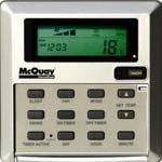
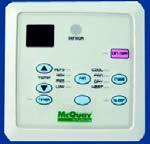
7 Product Features Can be done through Chiller Control Panel User friendly and versatile controls Main menu includes: Operation Timer Display Setting Alarm Whole system configuration Unique system configuration
8 Product Features 1. Less Start & Stop 3. Precise Temperature Control 2. Fast Cooling/ Heating 4. Low Starting Surge Running current Conventional air conditioner: High starting current Frequent on/off cycle Inverter air conditioner: Low starting current Smooth operation Hours of operation

9 Product Features Conventional System Inverter System
10 Product Features High & Low Pressure Switches Anti Freeze Protection Sensor Discharge Temperature Sensor Over Pressure Relief Valve Water Pressure Differential Switch Anti Freeze Heater on BPHE Compressor, Water Pump Overload Protector Back To Content
11 Schematic Diagram & Components
12 Schematic diagram 5ACV100CR Disch Temp 1 (Disch Comp 1) Inv Comp HP1 Suct Temp (Suction) Acc LP1 Cond In Temp 1 (Condenser) 4WV BPHE Out Temp (BPHE Out) Condenser Coil 1 BPHE In Temp (BPHE In) Cond Out Temp 1 (Def Comp 1) Liq Rvr Filter Drier EXV O/A Temp (Outdoor Air) Pump Disch Temp 2 (Disch Comp 2) Std Comp HP2 Acc LP2 4WV BPHE Condenser Coil 2 EWT (Water In) LWT (Water Out) Check valve Cond Out Temp 2 (Def Comp 2) FS Cooling Cap Tube Liq Rvr Heating Cap Tube Filter Drier Summary Pages Screen 3 Display Menu Defrost Sensor Display Menu Inverter Chiller Display Menu Discharge Sensor Check valve
 Control box assembly Expansion tank ( 8L) Water")
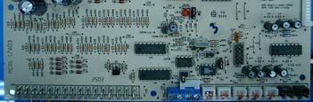
13 Components Fan guards Coil guards Variable speed fan motors (100%, 70% & 50%) Heat exchangers with gold fin as standard True dual circuits BPHE (Brazed plate heat exchanger) Control box assembly Expansion tank ( 8L) Water pump
 Main board Magnetic")
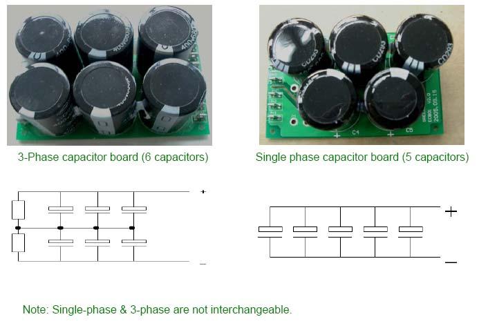
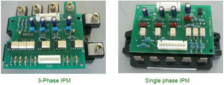
14 Components Unidirectional bridge diode IPM board (Intelligent power module) 3 phase rectifier bridge diode Fan capacitors Power board EMI filter Capacitor board PFC capacitor (Power factor correction) Main board Magnetic contactors


15 Components For Model 55, 75, 100 & 135 For Model 30
 Over voltage feedback Output short circuit")
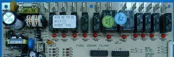
16 Components To convert rectified DC current +500VDC to respective desired voltages 12VDC relay MCU +5VDC IPM +15VDC Ensure stability of above voltages within power supply voltage fluctuation range ( VAC) Over voltage feedback Output short circuit protection
17 Components
18 Components
 18 psi open, 28 psi")

 Compressor OLP (overload protector) Variable")
19 Components High pressure switch (NC) 600 psi open, 480psi close. EXV (Electronics expansion valve Low pressure switch (NC) 18 psi open, 28 psi close. Chiller panel controller Differential pressure switch 4 Way valve Over pressure relief valve Anti freeze heater on BPHE Fixed speed scroll compressor (R410A) Pump OLP (overload protector) Compressor OLP (overload protector) Variable drive system compartment Fixed drive system compartment Variable speed scroll compressor (R410A)
20 Installation & Commissioning
21 Installation & Commissioning Unit Handling Unit Placement Maintenance Access Water Piping & Fitting Power Supply & Electrical Connection Preliminary Checking before Startup General Control Flow Chart

22 Installation & Commissioning 5ACV 100/135/210 CR
23 Installation & Commissioning Air Cooled Chiller are cooled by air, space restriction will reduces the air flow, decrease the cooling capacity, increase the power input and, in come cases, prevent the unit from operating because of an excess of condensation pressure. 5ACV equipped with propeller fan, which doesn t need ductwork on fan outlet. Direct effect of the wind on the discharge surface of the fan should be avoided. Enough clearance around the unit for maintenance works.

24 Installation & Commissioning Minimum clearances 5ACV30/55/75CR 5ACV100/135/210CR
25 Installation & Commissioning

26 Installation & Commissioning 5ACV 30 / 55 / 75 CR

27 Installation & Commissioning 5ACV 100 / 135 CR

28 Installation & Commissioning 5ACV 210 CR
29 Installation & Commissioning! Install piping with minimum bends and changes in elevation to minimize pressure drop. Consider the following: Vibration eliminators to reduce vibration and noise transmission to the building. Shut off valves to isolate the unit from the piping system during unit servicing. Manual or automatic air vent valves at the highest points of the chilled water piping. A means of maintaining adequate system water pressure (expansion tank or regulating valve) Temperature and pressure indicators located at the unit to air in unit servicing.
30 Installation & Commissioning! Water connection could be damaged by an excessive stress when screwing them. Use a second spanner to compensate the stress of tightening. Safety differential pressure switch is used to ensure adequate water flow to evaporator before starting up the unit. Balancing valve to regulate the amount of water flow rate through the unit.! It is mandatory to install a strainer at the inlet of the unit.
31 Installation & Commissioning Recommended Piping Connection
32 Installation & Commissioning Recommended Fuses & Cable Size Model 5ACV100CR 5ACV135CR 5ACV210CR Voltage Range ** / 3 / 50 Recommended Fuse (A) * Power Supply Cable Size (mm 2 ) * Number of Conductor Interconnection Cable Size (mm 2 ) * Model 5ACV30CR 5ACV55CR 5ACV75CR Voltage Range ** 230 / 1 / / 3 / / 3 / 50 Recommended Fuse (A) * Power Supply Cable Size (mm 2 ) * Number of Conductor Interconnection Cable Size (mm 2 ) * IMPORTANT: The figures shown in the table are for information purpose only. They should be checked and selected to comply with local/national codes of regulation. This is also subject to the type of installation and conduction used. * The appropriate voltage range should be checked with label data on the unit.
33 Installation & Commissioning!!! Before carrying out any operations on the electrical system, make sure that the unit is deenergized. It is important that the appliance is grounded. Before connecting the power supply lines, check that the available voltage value does not exceed the range specified in the electrical data being provided in Installation Manual.! It s recommended to check the correct sequence of the 3 supply phases RST before the unit start up.
34 Installation & Commissioning Check the power supply and grounding cable. Check that any voltage and phase variation in the power supply does not exceed the prefixed thresholds. Check that components of the external water circuit have been installed properly, and according to the manufacturer s instructions. Check that the filling of the hydraulic circuits, and make sure that the fluid circulation is correct, without any trace of leaks and air bubbles. Check that the direction of rotation of the pumps is correct. Adjust the liquid distribution network in such a way that the flow rate is within the specified range. Check that the water quality is up to the specification.
35 Installation & Commissioning Start No System On? Stop Inverter Comp Yes Yes No Clash between current & selected mode of operation? 60s Cooling? No Heating? No Stop pump Yes Yes Cooling mode Heating mode
36 Installation & Commissioning Cooling Mode Control Flow Chart Start ΔT = Actual Entering water temp Cooling water temp set point Pump on No No Yes Pump on for >3 min? ΔT > 2 C? No ΔT < 2 C for > 180s? Yes Frequency & EXV opening adjustment No No Yes Yes Inverter Comp Off? ΔT > 2 C? Stop Inverter Comp Yes 5s Shut Inverter 4WV & start Inverter O/Fan 30s Start Inverter Comp Return
37 Installation & Commissioning Heating Mode Control Flow Chart Start ΔT = Heating water temp set point Actual Entering water temp Pump on No No Yes Pump on for >3 min? ΔT > 2 C? No ΔT < 2 C for > 180s? Yes Frequency & EXV opening adjustment No No Yes Yes Inverter Comp Off? ΔT > 2 C? Stop Inverter Comp Yes 5s 30s Shut Inverter 4WV & start Inverter O/Fan Start Inverter Comp Return Back To Content
38 Self Diagnosis & Troubleshooting
39 Self Diagnosis & Troubleshooting Error Code Error Display Error Description Reset Control Measure (default) Pump System 1 System 2 (Variable Drive) (Fixed Drive) Comp Fan Comp Fan Phase Missing Phase Missing Manual Phase Seq Error Wrong phase Sequencing Manual Memory Error EEPROM read/write error Auto IPM Error IPM overcurrent or over heat Auto Continue.
40 Self Diagnosis & Troubleshooting Error Code Error Display Error Description Reset Control Measure (default) Pump System 1 System 2 (Variable Drive) (Fixed Drive) Comp Fan Comp Fan Entering Water Sensor Open/Short BPHE water in sensor error Auto Leaving Water Sensor Open/Short BPHE water out sensor error Auto VHx inlet Temp sensor Open/Short BPHE refrigerant in sensor error Auto VHx outlet Temp sensor Open/Short BPHE refrigerant out sensor error Auto Coil 1 inlet Temp Open/Short Coil in system 1 sensor error Auto Outdoor Air Sensor Open/Short Ambient Temp sensor error Auto Continue.
41 Self Diagnosis & Troubleshooting Error Code Error Display Error Description Reset Control Measure (default) Pump System 1 System 2 (Variable Drive) (Fixed Drive) Comp Fan Comp Fan Water Flow Error Cv Contact opened Manual Cool Mode Antifreeze Leaving water temp too low Auto Pump overload Pump OLP opened Auto Comp 1 Overload Comp 1 Overload Auto Comp 2 Overload Comp 1 Overload Auto Continue.
42 Self Diagnosis & Troubleshooting Error Code Error Display Error Description Reset Control Measure (default) Pump System 1 System 2 (Variable Drive) (Fixed Drive) Comp Fan Comp Fan Comp 1 Discharge Overheat Comp 1 discharge Overheat Auto Comp 1 Defrost Sensor Open/Short Coil Out system 1 sensor error Auto Comp 1 Suct Sensor Open/Short Suction comp system 1 sensor error Auto Comp 1 Discharge Sensor Open/Short Discharge Comp system 1 sensor error Auto Comp 2 Defrost sensor Open/Short Coil out system 2 sensor error Auto Comp 2 Discharge Sensor Open/Short/Overheat Discharge comp system 2 sensor error Auto Continue.
43 Self Diagnosis & Troubleshooting Error Code Error Display Error Description Reset Control Measure (default) Pump System 1 System 2 (Variable Drive) (Fixed Drive) Comp Fan Comp Fan OV/UN Voltage Comp. High Voltage (>490V) <460V, Auto OV/UN Voltage Comp. Low Voltage (<310V) >340V, Auto High Pressure 1 System 1 high pressure Auto Low Pressure 1 System 1 low pressure Auto High Pressure 2 System 2 high pressure Auto Low Pressure 2 System 2 low pressure Auto

44 Self Diagnosis & Troubleshooting 1. No response after poweron No response Yes Is main board LED light? Yes Check setting & operating condition Is connection IPM and Main Board OK? Yes Main Board or IPM Board Faulty No No Is R,S,T Input voltage normal? No Check Input power supply vac Connection Wire or Connector Faulty Rectifier Yes Is Power Board OK? No Change Power Board Power Board Main Board IPM
45 Self Diagnosis & Troubleshooting 2. LED on main board normal, but no output. LED lighted, No output Is Setting Parameter ok? No Change the Setting Parameter Yes Is Operating Condition OK? No Check Operating condition Yes Is main board s fuse ok? No Change Fuse Yes Replace main board
46 Self Diagnosis & Troubleshooting 3. Other functions normal but compressor not functioning Others OK, Comp not functioning Is fuse in DC loop ok? Yes Check operating conditions No Yes Is IPM OK? Check IPM No Is compressor ok? No Replace Compressor Yes Change Fuse
47 Self Diagnosis & Troubleshooting 4. Flow switch protection E01 Water flow error Short JK4 JK4 on main board Is water flow error persists? No Flow switch faulty or pump stopped. Yes Main board faulty, replace main board
48 Self Diagnosis & Troubleshooting 5. Over voltage protection E02 OV/UN Voltage Is Power supply > 490VAC? Yes Check the Electrical supply No Is Power supply < 460VAC? No Yes Power board error, rectify.
49 Self Diagnosis & Troubleshooting 6. Under voltage protection E03 OV/UN Voltage Is Power supply < 310VAC? Yes Check the Power supply No Is Power supply > 340VAC? No Yes Power board error, rectify.

50 Self Diagnosis & Troubleshooting 7. Pump overload protection E05 JK8 on main board Pump overload Is voltage of 97, 98 on heat relay VDC = 0 V No Yes Remove JK8, 97 & 98, check connectivity No Main board faulty Yes Pump overload


51 Self Diagnosis & Troubleshooting 8. Phase missing E06 Phase missing Is Voltage between R,S,T 415VAC ±20%? No Check incoming supply Yes 3 Phase supply Is JRST on main board 415VAC ±20%? Yes Main board faulty No Disconnect power, remove JRST, is voltage of socket 415VAC ±20%? Yes No To Check/replace EMI filter
52 Self Diagnosis & Troubleshooting Phase seq error E07 Interchange any 2 phase of R, S, T. Memory Error E08 Replace chip 24C02 Sensor Error E09, E12, E14, E20, E21, E22, E23, E24, E25, E30, E31, E33, E34 Check against the resistance cable.
53 Self Diagnosis & Troubleshooting 9. IPM protection E15 IPM Error Is IPM ok? Yes Replace Display Menu for Inverter No Inverter Chiller Is current at rated frequency ok? No Check compressor Comp Freq : 75Hz EXV : 320 Comp Amp : 9.7A Yes DC Bus : 555V Is IPM Error persists? No Normal

54 Self Diagnosis & Troubleshooting 9. IPM protection E15 Yes Use thermocouple. Is heat sink temperature >100 C? Yes Rectify Heat Sink Heat Compound No Use thermocouple. Is IPM temperature >100 C? No Main board faulty or wrong signal Yes Is heat compound dried out? No Change IPM IPM Yes Reapply heat compound
55 Self Diagnosis & Troubleshooting 10. Variable compressor overcurrent protection E16 Comp 1 overload Restart. Check compressor current on the handset. < 18 A? No Yes Check Compressor winding resistance Main board or compressor faulty Replace * For 5ACV30CR, Overload protection triggers when compressor current > 27 A
56 Self Diagnosis & Troubleshooting 11. Variable drive high pressure protection E17 & E27 High Pressure 1 Remove hp pin from main board. Remove OF. Is high pressure switch ok? No Replace Yes Check AC system for overload Rectify
57 Self Diagnosis & Troubleshooting 12. Variable drive low pressure protection E18 & E28 Low Pressure 1 Is low pressure switch ok? No Replace Yes Check AC system for low pressure Rectify
58 Self Diagnosis & Troubleshooting 13. Variable compressor high discharge temperature protection Comp 1 Discharge Overheat > 110 C? Yes Compressor stops Temp sensor ok? (<100 C?) No Replace Check AC system Rectify
59 Self Diagnosis & Troubleshooting 14. Fixed compressor overcurrent protection Comp 2 Overload Check VAC Check on compressor winding resistance, is it to spec? Check continuity. No Rectify Is supply voltage ok? Yes No Rectify Yes Check on Compressor insulation, is it ok? Check continuity. No Rectify Check current reading on handset against actual reading, is it very big different? Yes No Normal Yes Current sensing circuit error. Replace main board

 No Replace power Board")
60 Self Diagnosis & Troubleshooting Power Board Checking Power Board Power Board Checking Is Power board DCIN voltage normal? No Check bridge diode Yes Is JPpower/DC OUT output normal? Yes Main Board or IPM Board Faulty DCIN (+590VDC) No Replace power Board JPPower (+12Vdc & 7Vdc) DCOut (+15Vdc)


61 Self Diagnosis & Troubleshooting IPM Board Checking P N Use multimeter to check the Vdc between the P and N. The voltage should be around 590Vdc


62 Self Diagnosis & Troubleshooting Power Supply Checking Use the multimeter to check the power supply to controller. Refer to any of the 2 phase of supply (R&S, S&T or R&T). The supply should be 415VAC

63 Self Diagnosis & Troubleshooting Fuse Checking Use multimeter to check the continuity of the fuse. Fuse with sound BEEP is ok

64 Self Diagnosis & Troubleshooting Fuse Checking Use multimeter to check the continuity of the fuse. Fuse with sound BEEP is ok


65 Self Diagnosis & Troubleshooting Compressor Checking Check Compressor Check on compressor winding resistance, is it ok? No Change Compressor Yes Check on Compressor insulation, is it ok? No Change Compressor Yes Is compressor short body? Yes Change Compressor No Compressor OK

66 Self Diagnosis & Troubleshooting Bridge Diode Checking + ~ ~ Use multimeter to check the continuity of the bridge diode.
67 Resistance Table Low Temperature Sensor (Coil sensor and room/ambient sensor) Temperature Resistance Temperature Resistance ( C) (k Ω) ( C) (k Ω) When Temp = 25 C, Resistance = 5 kω
68 Resistance Table High Temperature Sensor (Discharge sensor) Temperature Resistance Temperature Resistance ( C) (k Ω) ( C) (k Ω) When Temp = 100 C, Resistance = 6.5 kω Back To Content
69 Centralized Control Solution: Smart Manager

70 Smart Manager Mini Chiller Nim FCU Mini Chiller Chiller Panel Controller Chiller Panel Controller Smart Manager Nim Netware 2/ SLM3 or wireless controller Netware 2/ SLM3 wireless controller FCU Support up to 50 Chillers in one chiller BUS and up to 120 FCUs in one NIM BUS. Mini Chiller Nim FCU Chiller Panel Controller Netware 2/SLM3 or wireless controller Can Support Up to 50 Chillers On the C BUS Can Support up to 120 FCUs On the NIM BUS


71 Smart Manager Programmable Energy Saving Timer Chiller One set of 7 days programmable operating schedules (2 ON/ timers per day) FCUs Five set of 7 days programmable operating schedules. (2 ON/ timers per day)
72 Smart Manager Holiday Setting (FCU) 10 holidays with duration of 99 days each can be set. All FCUs & Chiller will be turned during the holiday period. Timer Schedules are disabled during holiday period.
73 Smart Manager Display up to 46 types of Chiller Fault/ Alarm and 6 types of FCUs Fault/ Alarm New Alarm 1 [Ch 3] Comp 1 Overload 06/04/05 12:00 am Whenever Smart Manager receives a new alarm from Chiller or FCUs,, an alarm message will pop up on the LCD screen; shows type of alarm, alarm occurred time, date and unit. Backlight blinking and alarms buzzer produces beeping sound (if it s s set ON )
 Setting")
74 Smart Manager Memory Backup, Alarm Memory for Chiller & FCUs Real Time Clock (RTC) Settings Allows user to set the time and date Password Protection For advance parameter settings (Chiller) Setting Protection
75 Smart Manager Defrost & Discharge Sensor Temp Display (Chiller) Defrost Sensor Discharge Sensor Comp 1 : 12.8 C Comp 1 : 36.5 C Accumulative Compressor Run Time For servicing purpose


76 Smart Manager Component Smart Manager Chiller Panel Controller Mini Chiller main board Netware 3 SLM3 NIM FCU main board
77 Smart Manager Bus Wiring Network
 Chiller Panel 1 (Slave) Chiller")

78 Smart Manager Chiller Bus Chiller Panel 0 (Master) Chiller Panel 1 (Slave) Chiller Panel 2 (Slave) Chiller ID 0 Chiller ID 1 Chiller ID 2 B CN8 CN8 Chiller BUS A Smart Manager
79 Smart Manager NIM BUS Smart Manager Supply +12 VDC 120 Units of FCU NIM Master NIM Master NIM Master Wired Controller (Netware 3)
80 Smart Manager NIM BUS FEATURES Fan Coil Unit Monitor FCU s status and control FCU s settings (global, group or individual) Alarm (6 types of FCU fault) Five sets 7 days programmable timer (2 ON/ timer) 10 Holidays setting (turn all units during holiday period)
81 Smart Manager NIM BUS 120 groups Each group must consist one master Maximum 16 FCUs in one group including master Global Control Group control Individual control
82 Smart Manager Smart Manager Menu Go into FCU summary pages to Control and Display status of FCU SMART MANAGER Fan Coil Unit Chiller Settings Smart Manager Configuration Go into Chiller summary pages to Control and Display status of Chiller
83 Smart Manager Menu Structure Chiller Summary Pages Hold ESC 1s Select Chiller Smart Manager Hold ESC 1s Select Setting SM Setting Hold ESC 1s Select Fan Coil Unit FCU Summary Pages
84 Smart Manager Smart Manager Setting Priority Setting SM SETTINGS Priority : FCU Cool Threshold : 50 % Heat Threshold : 50 % Set to FCU, Chiller running mode is determined by FCU status base on threshold value If one FCU is ON, Chiller turn ON automatically Manual ON the Chiller will be turn automatically by the setting if all the FCU is If all FCUs are, Chiller turn automatically
85 Smart Manager Smart Manager Setting Priority Setting SM SETTINGS Priority : Chiller Cool Threshold : 50 % Heat Threshold : 50 % Set to Chiller, Chiller running mode is determined by Chiller status itself If Chiller is, No FCU can be turned ON Manual ON the FCU will be turn automatically by the setting If Chiller turn ON, FCUs can be turned ON or
86 Smart Manager Smart Manager Setting Priority Setting SM SETTINGS Priority : None Cool Threshold : 50 % Heat Threshold : 50 % Set to None, Operation Between Chiller and FCU isolated This priority setting is the factory setting
87 Smart Manager Threshold Setting SM SETTINGS Priority : FCU Cool Threshold : 60 % Heat Threshold : 70 % Must Set to FCU 50% Value setting 100% Ensure the Running Mode Of Chiller Total of FCU 10 No. of FCU in Cool Mode 7 6 No. of FCU in Heat Mode 3 4 Cool Threshold (C) Heat Threshold (H) Running Mode of Chiller cooling cooling If C 60, Run as Cooling mode (current setting mode) cooling cooling Heating If 40<C<60, remain as the current mode Heating If H 70, Switch to Cooling Mode
88 Smart Manager FCU Unit Addres Setting Adjust the Dipswitch (DSW1) to assign Group Address setting Adjust the Dipswitch (DSW2) to assign FCU Unit setting
89 Smart Manager Connection to Smart Manager CN2 ~ Connect to Wired Controller CN3 ~ Connection of NIM Bus to Smart Manager CN1 ~ Connect to Main Board (WIV3)
90 Smart Manager Installation of Smart Manager A B Smart Manager A B
91 Smart Manager Menu Structure Diagram for FCU Operation Menu Press ENTER Press ENTER Setting Menu Summary Pages Press and Hold ENTER for 1s Main menu Unit Selection Menu Timer Menu Alarm Menu
92 Smart Manager Unit Selection Menu We can control the FCU as : Global Group Individual Unit Selection : Select All Select Group Select One Display the Global Master (G0U0) status and control all FCUs setting at once Display the Group Master (G1U0) status and control all FCUs setting in that group at once Only display the chosen FCUs and control the FCUs setting
93 Smart Manager Method 1 Select the Unit Selection and press ENTER Changing Display Unit Press & hold ENTER 1s (in Summary Pages) Unit Selection : Select All Select Group Select One 01/01/ :00am Status Mode Set Temp Fan Room Temp Unit : : Cool : 24 o C : High : 27 o C : G0U0 Summary Page Unit : All G1 G0U1
94 Smart Manager Method 2 Changing Display Unit Press & hold UP or DOWN Key 1s (in Summary Pages) to scroll and display each FCU unit in the network 01/01/ :00am Status : Mode : Cool Set Temp : 24 o C Fan : High Room Temp : 27 o C Unit : G0U0 Unit : GXUX will keep on changing to show ALL the FCU units exist in the network Let Off the UP or DOWN Key until the GXUX that u wish to display
95 Smart Manager Summary Pages FCU Menu Structures Press Up and Down Key for page scrolling And Display the Operation Status of FCU 01/01/ :00 am 01/01/ :00 am Status Mode Set Temp Fan Room Temp Unit : ON : Cool : 24 o C : High : 27 o C : G0U0 Swing : Yes Sleep : No Compressor : Schedule : 1 Timer : Disable
96 Smart Manager Main Menu of FCU Control the Operation Password Protected Advanced Parameters Setting & Panel Option MAIN MENU Operation Menu Setting Menu Timer Menu Alarm Menu Clock & Date Setting Timer On/Off Schedule Holiday Off Duration Record 20 erasable alarm histories
97 Smart Manager Operation Menu Change the Operation Settings of FCU 01/01/ :00 am 01/01/ :00 am Status Mode Set Temp Fan : ON : Cool : 24 o C : High Swing : Yes Sleep : No Schedule : 1 Timer : Disable Enable or Disable the Timer Schedule Select the Timer Schedule
98 Smart Manager Panel Option Setting of the Panel itself Backlight : Normal Buzzer : ON Screen Saver : Disable Timeout : 5m Contrast : 50% Brightness : Medium Temp Unit : o C Create a Beeping sound whenever It trigger any alarm Temperature Unit can be set either o For o C
99 Smart Manager Timer Menu Set Time: hh mm Set Date: yy mm dd MAIN MENU Clock Setting Date Setting Timer Schedules Holiday
100 Smart Manager Timer Schedule 5 sets of programmable timer schedules 7 days of timer schedule (Sun to Sat) 2 ON/ events per day Assigning timer schedule as Global (All FCUs), group (Groups of FCU) or individual (one FCU) Manually On/Off can always override the timer schedule SCHEDULE SETTINGS Schedule 1 Schedule 2 Schedule 3 Schedule 4 Schedule 5 Timer 1 Timer 2 ON ON Sun Mon Tue Wed
101 Smart Manager Assigning ON/ Schedule After set the 7 days programmable On/Off Timer in Timer Schedule (up to 5 Sets) Select ONE set of timer schedule in Operation Menu Enable the Timer in order to activate the timer schedule OPERATION MENU Swing : Yes Sleep : No Schedule : 1 Timer : Enable
102 Smart Manager Holiday Setting All the FCU and Chiller will be turn Temporally Disable all the timer schedules 10 sets of Holiday Schedules 99 days duration for each holiday FCU can be opened manually ; FCU will switch off at 00:00am for the following day if it still in holiday mode SCHEDULE SETTINGS Holiday 1 Holiday 2 Holiday 3 Holiday 4 Holiday 5 SCHEDULE SETTINGS Holiday 6 Holiday 7 Holiday 8 Holiday 9 Holiday 10
103 Smart Manager Holiday Setting How to set a Holiday schedule? Set Holiday 1 Month : 1 Day : 25 Duration : Disable Specify the month and date for Holiday starting period Duration for the Holiday is from 1~99 days A sign [H] will be shown in Summary Page during holiday period
104 Smart Manager Example Christmas Holiday : 24/12/10 ~ 26/12/10 Duration : 3 days Set Holiday 1 Month : 12 Day : 24 Duration : 3 Start from 00:00am, 24/12/03 Holiday Mode will be activated Holiday Mode will be deactivated starting from 00:00am, 27/12/03
105 Smart Manager New Alarm Display Faulty or Alarm is triggered An New Alarm or Alarms will pop up on the LCD Beeping sound Backlight blinking Alarm occurred type Alarm 1 Outdoor coil Sensor missing [G0U0] Alarm occurred Unit (FCU ID) 01/01/00 12:00am Alarm occurred Date Alarm occurred time Back To Content
106 Selection Software


107 Smart Manager Independent Chilled Water FCU selection software. Independent Mini Chiller selection software. McQuay Chilled Water Product Selection Virtual Piping Sizing Back To Content
108 Competitor s Product Comparison


109 Competitor s Products Comparison Product Range 2HP 3HP 5HP 7HP 9HP 13HP 20HP 85HP 250HP OYLM M5ACVCR DAIKIN EWAQ / YQ UWAXP CARRIER AquaSnap BRIGHT BHLRCFZ Using R410A Refrigerant Using R407C Refrigerant
110 Competitor s Products Comparison INVERTER MINI CHILLER OYLM M5ACV030CR 3HP DAIKIN EWYQ007ACV3HP BRIGHT BHLRCF10Z Refrigerant R410A R410A R407C Capacity, BTU/hr 27,000 24,225 33,096 Heating Capacity, BTU/hr 33,000 29,787 39,238 Noise, dba COP Height, inch Width, inch Depth, inch Volume, ft
111 Competitor s Products Comparison INVERTER MINI CHILLER OYLM M5ACV055CR 5HP DAIKIN UWAXP125AY1 BRIGHT Refrigerant R410A R407C Capacity, BTU/hr 50,000 42,700 Heating Capacity, BTU/hr 66,000 Noise Indoor, dba 62 COP 6.59 Height, inch Width, inch Depth, inch Volume, ft
112 Competitor s Products Comparison INVERTER MINI CHILLER OYLM M5ACV075CR 7HP DAIKIN UWAXP190AY1 BRIGHT Refrigerant R410A R407C Capacity, BTU/hr 70,000 64,900 Heating Capacity, BTU/hr 75,000 Noise Indoor, dba 65 COP 7.75 Height, inch Width, inch Depth, inch Volume, ft
113 Competitor s Products Comparison INVERTER MINI CHILLER OYLM M5ACV100CR 9HP DAIKIN UWAXP250AY1 BRIGHT Refrigerant R410A R407C Capacity, BTU/hr 95,000 85,400 Heating Capacity, BTU/hr 100,000 Noise Indoor, dba 63 COP 7.92 Height, inch Width, inch Depth, inch Volume, ft
114 Competitor s Products Comparison INVERTER MINI CHILLER OYLM M5ACV135CR 13HP DAIKIN UWAXP375AY1 BRIGHT Refrigerant R410A R407C Capacity, BTU/hr 131, ,000 Heating Capacity, BTU/hr 141,500 Noise Indoor, dba 67 COP 8.36 Height, inch Width, inch Depth, inch Volume, ft
115 Competitor s Products Comparison INVERTER MINI CHILLER OYLM M5ACV210CR 20HP DAIKIN UWAXP500AY1 BRIGHT Refrigerant R410A R407C Capacity, BTU/hr 200,00 171,000 Heating Capacity, BTU/hr 210,000 Noise Indoor, dba 85 COP 8.97 Height, inch Width, inch Depth, inch Volume, ft Back To Content
116 Thank You Back To Content
Applica. First Edition uly 2005
 McQuay y Smart t Manager er Chilled Water System Applica pplication Manual First Edition Jul uly 2005 Introduction Introduction... Introduction-1 Section 1: Networ ork k Interface Module (NIM) and Netwar
Amendment Sheet. Nomenclature M 5 AC V 100 C R - F X AA. Code : M5ACV Date : Superceded : M5ACV
 Amendment Sheet Code : M5ACV-2005-0002 Date : 08-05-2006 Superceded : M5ACV-2005-0001 Nomenclature Production spec variation Type of ref. connection X : Not applicable Electrical A : 220-240V/1Ph/50Hz
McQuay HydroflexTM Residential and Light Commercial Chilled Water System
 Advanced, affordable chilled water solutions. McQuay HydroflexTM Residential and Light Commercial Chilled Water System McQuay Hydroflex System Chilled Water Solutions Made Affordable Benefits: Advanced
2. FEATURES. Gold aluminum fin is offered as standard material of the condenser heat exchanger of this series of chiller.
 2. FEATURES TRUE DUAL CIRCUITS BPHE The true dual BPHE puts the secondary circuit (water) in contact with 2 primary circuits (refrigerant). So even if one primary circuit is shut off, each secondary channel
Service Manual. Chiller unit MQH R 410A. Release Date Rev Review Date november
 Service Manual Chiller unit MQH R 410A Release Date Rev Review Date november 2008 ----- ----- MQH R410A ELECTRONIC CONTROL CONTROL PANEL The control panel allows the user to carry out all the operations
Operating Functions Temperature Parameters
 Operating Functions Temperature Parameters Room set temperature (T set) Room ambient temperature (T amb) Fundamental Functions After powered on, no matter when the compressor is started, the time interval
USER'S OPERATING INSTRUCTIONS
 SAT-2 Thermostat COOL FAN DRY HEAT AUTO SLEEP SWING AUTO ZONE SUN MON TUE WED THU FRI SAT HEATER ON OFF ERR UNIT USER'S OPERATING INSTRUCTIONS CONTENTS Page Introduction 3 Features Summary 3 Display 4
SERVICE MANUAL. Inverter Wall Mounted Single Split. MODELS Cooling Only. Heatpump SM-5WM-Y-NA-B1
 SERVICE MANUAL Inverter Wall Mounted Single Split MODELS Cooling Only FTKB09AXVJU FTKB12AXVJU FTKB18AXVJU FTKB24AXVJU FTKN09AXVJU FTKN12AXVJU FTKN18AXVJU FTKN24AXVJU Heatpump FTXB09AXVJU FTXB12AXVJU FTXB18AXVJU
Air-Cooled Mini Chiller. Models: AMAC 040 A/AR AMAC 050 A/AR AMAC 058 A/AR AMAC 075 B/BR AMAC 100 B/BR AMAC 125 B/BR. Manual No: TMA-AMAC-1161
 Models: AMAC 040 A/AR AMAC 050 A/AR AMAC 058 A/AR AMAC 075 B/BR AMAC 100 B/BR AMAC 125 B/BR Air-Cooled Mini Chiller Manual No: TMA-AMAC-1161 REGISTERED ISO 9002 CONTENTS PAGE 1. NOMENCLATURE SYSTEM...
SPECIFICATIONS for AIR CONDITIONING CONTROLLER ZONE CONTROL
 SPECIFICATIONS for AIR CONDITIONING CONTROLLER ZONE CONTROL 1. INTROUCTION Zone control is a two pieces fan coil thermostat available for Heat/Cool versions. Its application is for the duct type system
Container Refrigeration
 Container Refrigeration OPERATION AND SERVICE for 69NT40-561-019 Evergreen Container Refrigeration Units Table 3 6 Controller Alarm Indications (Sheet 1 of 8) AL03 Loss of Superheat Control AL05 Manual
Part 3 Troubleshooting
 Part Troubleshooting What is in this part? This part contains the following chapters: Chapter See page Troubleshooting 2 Error Codes: Hydro-box 7 Error Codes: Outdoor Units Error Codes: System Malfunctions
REMOTE CONTROL FOR CHILLER MYCHILLER
 REMOTE CONTROL FOR CHILLER MYCHILLER GENERAL FEATURES... 3 MAIN FUNCTIONS AND EQUIPMENT:... 3 LCD DISPLAY... 4 KEYBOARD... 5 BOARD CONFIGURATION... 7 LIST OF MAIN PARAMETERS... 7 CONFIGURATION OF MAIN
Safety & Installation Instructions
 Model 8800 Universal Communicating Thermostat Safety & Installation Instructions READ AND SAVE THESE INSTRUCTIONS Table of contents Installation Installation location recommendations... 2 Thermostat mounting...
SERVICE MANUAL MUZ-D30NA / - MUZ-D36NA / - MUY-D30NA / - MUY-D36NA / - OUTDOOR UNIT. No. OBH502. Models HFC. Revision E: REVISED EDITION-E R410A
 Revision E: Capacity corrections have been corrected [7-1. 2), 3)]. OBH502 REVISED EDITION-D is void. OUTDOOR UNIT SERVICE MANUAL HFC utilized R410A. OBH502 REVISED EDITION-E Models MUZ-D30NA / - 1 / -
All side discharge units are having high pressure switch (LP switch- Optional) and time delay relay. Compressors are scroll type, Copeland make.
 and time delay relay. Compressors are scroll type, Copeland make.") All outdoor units are designed to perform satisfactorily at 52 C, with the option of either top discharge condensing units, with Copeland reciprocating scroll compressors. All top discharge condensing
All outdoor units are designed to perform satisfactorily at 52 C, with the option of either top discharge condensing units, with Copeland reciprocating scroll compressors. All top discharge condensing
Refrigeration Controller Operator s Manual (HRC) PO Box 6183 Kennewick, WA
 PO Box 6183 Kennewick, WA") Refrigeration Controller Operator s Manual (HRC) PO Box 6183 Kennewick, WA 99336 www.jmcvr.com 1-509-586-9893 Table of Contents TABLE OF FIGURES...1 OVERVIEW OF THE HRC CAPABILITIES...2 INSTALLATION AND
Refrigeration Controller Operator s Manual (HRC) PO Box 6183 Kennewick, WA 99336 www.jmcvr.com 1-509-586-9893 Table of Contents TABLE OF FIGURES...1 OVERVIEW OF THE HRC CAPABILITIES...2 INSTALLATION AND
INSTALLATION & OPERATION MANUAL
 DC INVERTER AIR TO WATER HEAT PUMP AC series Heating & Cooling series CX30 INSTALLATION & OPERATION MANUAL Version 1.5 1 Table of Contents Safety Precautions... 3 Components... 4 Hydronic piping and design
Troubleshooting & Reference
 Troubleshooting & Reference Error Code Descriptions Description of Error Codes - 9, 12 MBH code malfunction Error Display Repair Method 1 Storage slug (EEPROM) 2 Indoor PCB malfunction 3 Anti-freezing
Replaceable LED modules. Sleep or unattended mode. Auto-silence and auto-acknowledge
 Replaceable LED modules 11 Alarm Sequences as per ISA-18.1 standard Each channel/window fully field programmable RS232 or RS485 MODBUS-RTU communication Repeat relay for each window and multifunction relays
Models: A5ACV 30 CR A5ACV 55 CR A5ACV 75 CR A5ACV 100 CR A5ACV 135 CR A5ACV 210 CR A5ACV Air-Cooled Chiller (R410A Inverter Series)
") Models: A5ACV 30 CR A5ACV 55 CR A5ACV 75 CR A5ACV 100 CR A5ACV 135 CR A5ACV 10 CR A5ACV - 007 Air-Cooled Chiller (R410A Inverter Series) 1. NOMENCLATURE Production spec variation Type of ref. connection
Models: A5ACV 30 CR A5ACV 55 CR A5ACV 75 CR A5ACV 100 CR A5ACV 135 CR A5ACV 10 CR A5ACV - 007 Air-Cooled Chiller (R410A Inverter Series) 1. NOMENCLATURE Production spec variation Type of ref. connection
Rev B, 9/2/2009. Kodiak Chiller Overview
 930-0001 Rev B, 9/2/2009 Kodiak Chiller Overview Presentation Outline Phone: 781-933-7300 Lytron Technical Support Contact Information 3 Introduction 4 Part I: Unpacking 5 Part II: Installation 7 Part
SERVICE MANUAL MUZ-D30NA MUZ-D30NA- U1 MUZ-D36NA MUZ-D36NA- U1 MUY-D30NA MUY-D36NA OUTDOOR UNIT. No. OBH502. Wireless type Models HFC R410A
 OUTDOOR UNIT SERVICE MANUAL HFC utilized R410A. OBH502 Wireless type Models MUZ-D30NA MUZ-D30NA- U1 MUZ-D36NA MUZ-D36NA- U1 MUY-D30NA MUY-D36NA Indoor unit service manual MSZ-D NA Series (OBH501) MSY-D
Zeta Rev LN HP Prochill Bluebox Print Date: 07/17/2017
 Zeta Rev LN HP 10.2 Configured unit accessories 1PS - One user-side pump with tank LN - Low noise RG - Condensation control with fan speed regulator CSP - Set point compensation depending on external air
Chilled Water System Solution
 All Product Catalogue AP-MSM-07A Chilled ater System Solution Engineered for flexibility and performance. CONTENTS: Chilled ater System Solution McQuay Offers ; Comprehensive Solution... 2 In Air Conditioning
MANUAL FOR AIR COOLED INDUSTRIAL CHILLERS MODEL: UCS-10A
 MANUAL FOR AIR COOLED INDUSTRIAL CHILLERS MODEL: UCS-10A Universal Chilling Systems, LLC. 2 Unit Manual Contents 1. Specification 2. Transportation 3. Unit Installation 4. Electrical Installation 5. Commissioning
OPERATION INSTRUCTIONS DEMAND DEFROST CONTROL BOARD MODEL FOR USE WITH MODELS: AFFINITY, ECHELON, ACCLIMATE HEAT PUMP SERIES
 OPERATION INSTRUCTIONS DEMAND DEFROST CONTROL BOARD MODEL 500644 FOR USE WITH MODELS: AFFINITY, ECHELON, ACCLIMATE HEAT PUMP SERIES A047-001 FIGURE 1: Demand Defrost Control Module ANTI-SHORT CYCLE DELAY
Smart Temp. Model
 Smart Temp Model 42-160 SINGLE STAGE PROGRAMMABLE THERMOSTAT 1 Heat / 1 Cool Single Stage Thermostat. 5+2 Programmable, Compatible with Gas Heat & Heat Pump System Installation and Operation Manual SPECIFICATIONS:--------------------------------------------------------------------------------
Multiple Battery Cabinets Dual-Lite TRN. External Maintenance Switch Configuration Options. External Maintenance Switch Options
 Table 4 External Maintenance Switch Configuration Options External Maintenance Switch Options Installed with Interlock Option Option Auxiliary Contact Status open = On Test position or Maintenance position,
DC INVERTER AIR TO WATER HEAT PUMP AC series Heating & Cooling series CX30
 DC INVERTER AIR TO WATER HEAT PUMP AC series Heating & Cooling series CX30 Installation and Operation Manual Version 1.7 1 Table of Contents Safety Precautions... 3 Components... 4 Hydronic piping and
User Manual. Dryer Controller M720
 User Manual Dryer Controller M720 Hardware version 1.00 Software version 1.00 Preliminary version Manual M720 Dryer controller Page 1 of 42 Document history Preliminary version: - Created in April, 2009
Dryer Controller M720
 User Manual Dryer Controller M720 Hardware version 2.00 Software version 2.00 Manual M720 Dryer controller Page 1 of 60 Document history Preliminary version: - Created in April, 2009 Hardware Version 2.00,
Epsilon Echos kw. General information Air-Water unit with scroll compressors driven by DC inverter. Unique selling points
 Epsilon Echos+ 5 38 kw General information Air-Water unit with scroll compressors driven by DC inverter Configuration /LN: Low noise unit /HP: Reversible heat pump /LE /HP: Reversible condensing unit Unique
3.2 E1 Outdoor Unit PCB Abnormality E4 Actuation of Low Pressure Sensor E5 Compressor Motor Lock 3 52
 Error Codes: Outdoor Units Error Codes: Outdoor Units Part. What Is in This Chapter? Introduction Overview In the first stage of the troubleshooting sequence, it is important to correctly interpret the
Inverter Wall Mounted Series
 PCXRY14 Inverter Wall Mounted Series R410A Products manufactured in an ISO certified facility. This document contains the most current product information as of this printing. 2014-09 Printed In Malaysia
T-32-TS Touchscreen Thermostat. Installation Manual
 T-32-TS Touchscreen Thermostat Installation Manual TABLE OF CONTENTS Introduction...4 Getting Started...5 Installing the Thermostat...6, 8 Disassembly...6 Thermostat Location...6 Mounting the Subbase...6,
SERVICE MANUAL MUZ-DM25VA - E1, ER1, ET1 MUZ-DM35VA - E1, ER1, ET1 OUTDOOR UNIT. No. OBH751. Models HFC R410A
 OUTDOOR UNIT SERVICE MANUAL HFC utilized R410A. Models MUZ-DM25VA - E1, ER1, ET1 MUZ-DM35VA - E1, ER1, ET1 Indoor unit service manual MSZ-DM VA Series (OBH750) CONTENTS 1. TECHNICAL CHANGES 2 2. PART NAMES
Product Manual SZ1009
 Product Manual SZ1009 Conventional Heating & Cooling Thermostats with Heat Pump Mode Communicating Thermostats Description The SZ1009 is a microprocessor-based mable thermostats designed for conventional
Fast Track Troubleshooting
 Fast Track Troubleshooting Models Covered: RF266AD**/XAA French Door Refrigeration IMPORTANT SAFETY NOTICE For Technicians Only This service data sheet is intended for use by persons having electrical,
B. Unit construction shall comply with ASHRAE 15 Safety Code, NEC, and ASME applicable codes (U.S.A. codes).
.") Guide Specifications PART 1 GENERAL 1.01 SYSTEM DESCRIPTION Microprocessor controlled, air-cooled liquid chiller utilizing scroll compressors, low sound fans, hydronic pump system and optional fluid storage
Guide Specifications PART 1 GENERAL 1.01 SYSTEM DESCRIPTION Microprocessor controlled, air-cooled liquid chiller utilizing scroll compressors, low sound fans, hydronic pump system and optional fluid storage
HP727S. Single speed swimming pool heat pump controller Operation manual TABLE OF CONTENTS
 HP727S Single speed swimming pool heat pump controller Operation manual TABLE OF CONTENTS 1. General Description 2. Specifications 3. Installation Instructions 4. Electrical Wiring 5. Instrument Wiring
Tempered Water Logic Control OPERATION l TROUBLE SHOOTING
 Tempered Water Logic Control OPERATION l TROUBLE SHOOTING English For MPE Multiple Chiller Units Control Panel TEMPERED WATER SYSTEMS L-2199 Rev. 20080223 Revision: L-2199 20101104 *** IMPORTANT NOTICE
30GH Air-Cooled Liquid Chillers 30GH Nominal cooling capacity kw
 Air-Cooled Liquid Chillers Nominal cooling capacity 21-94 kw Carrier is participating in the Eurovent Certification Programme. Products are as listed in the Eurovent Directory of Certified Products. The
100 TON AIR-COOLED SCROLL PACKAGED. Call us today! (800) SPECIFICATIONS GENERAL DIMENSIONS ELECTRICAL DATA ADDITIONAL INFORMATION
 SPECIFICATIONS GENERAL DIMENSIONS ELECTRICAL DATA ADDITIONAL INFORMATION") 100 TON AIR-COOLED SCROLL PACKAGED SPECIFICATIONS Call us today! (800)341-4297 Trane Portable Packaged Air Conditioner units contain the best compressor technology available, in order to achieve the highest
100 TON AIR-COOLED SCROLL PACKAGED SPECIFICATIONS Call us today! (800)341-4297 Trane Portable Packaged Air Conditioner units contain the best compressor technology available, in order to achieve the highest
KSIM20912-H216 KSIM30912-H216 KSIM40912-H216
 SERVICE MANUAL KLIMAIRE AIRCONDITIONER KSIM DC INVERTER MULTI TYPE KSIM20912-H216 KSIM30912-H216 KSIM40912-H216 DC MULTI OUTDOOR UNITS CONTENTS 1. General information of Outdoor Units...3 2 Features...4
Air Cooled Module Water Chiller
 Air Cooled Module Water Chiller Installation, operation and technical manual Heat pump / Cooling only R22 refrigerant 33KW, 65KW 3PH, 380V~400V, 50Hz Haier Commercial Air Conditioning MANUAL CODE: SYJS-015-08REV.0
MODEL YVAA EQUIPMENT PRE-STARTUP AND STARTUP CHECKLIST CUSTOMER: LOCATION: ADDRESS: CUSTOMER ORDER NO: PHONE: JCI CONTRACT NO: JOB NAME:
 Supersedes: 201.28-CL2 (817) Form 201.28-CL2 (1017) MODEL YVAA EQUIPMENT PRE-STARTUP AND STARTUP CHECKLIST CUSTOMER: LOCATION: ADDRESS: PHONE: JOB NAME: CUSTOMER ORDER NO: JCI CONTRACT NO: CHILLER MODEL
NO. F ISSUED: JUN. 18, 2008 REVISED: JUN. 17, 2011 HOSHIZAKI SELF-CONTAINED CRESCENT CUBER KM-100A KM-125A MODEL SERVICE MANUAL
 NO. F003-756 ISSUED: JUN. 18, 2008 REVISED: JUN. 17, 2011 HOSHIZAKI SELF-CTAINED CRESCENT CUBER MODEL KM-100A KM-125A SERVICE MANUAL IMPORTANT This manual should be read carefully before the icemaker is
WIRING DIAGRAMS R410A MODELS PAC 2OAC/2OACH CAC OWC PWC
 WIRING DIAGRAMS R410A MODELS 2OAC/2OACH PAC CAC PWC OWC WIRING 02172017 TABLE OF CONTENTS PAGE 2OACH Deluxe Portable Air-cooled Heat Pump Electronic Controller... 2-3 Piping Schematic... 4 Single Phase
Installation Instructions / User s Manual TSTAT0406 and TSTAT0408
 997-060180-5 Installation Instructions / User s Manual TSTAT0406 and TSTAT0408 4 HEAT 2 COOL DUAL FUEL TSTAT0406 & TSTAT0408-4 WIRE CAPABLE THERMOSTAT (NAXA00201DB Daughter Board sold separately) LEFT
SERVICE MANUAL 42QHF009DS* 42QHF012DS* 42QHF018DS* 42QHF022DS* 38QUS009DS* 38QUS012DS* 38QUS018DS* 38QUS022DS* Indoor unit.
 SERVICE MANUAL Indoor unit Outdoor unit 42QHF009DS* 42QHF012DS* 42QHF018DS* 42QHF022DS* 38QUS009DS* 38QUS012DS* 38QUS018DS* 38QUS022DS* INDEX PART1 GENERAL INFORMATION PART2 ELECTRICAL DIAGRAM PART3 TROUBLE
1025, BOUL. MARCEL-LAURIN INSTRUCTION MANUAL FOR WATER COOLED ENVIROCHILL CHILLER. Prepared par Claude Gadoury, P. Eng MTL TECHNOLOGIES INC.
 WYETH-AYERST CANADA INC. 1025, BOUL. MARCEL-LAURIN S T - L A U R E N T, Q U É B E C INSTRUCTION MANUAL FOR WATER COOLED ENVIROCHILL CHILLER MODEL P448800LT--55WC--22C66S Prepared par Claude Gadoury, P.
Product Manual SZ1022/SZ1031/SZ1035/
 Product Manual SZ1022/SZ1031/SZ1035/ Conventional Heating & Cooling Thermostats Communicating Thermostats Description The SZ1022, SZ1031, and SZ1035, are microprocessorbased mable thermostats designed
AC&R Controller RWR Basic Documentation VR2002 for water to water heat pump units
 AC&R Controller RWR470.10 Basic Documentation VR2002 for water to water heat pump units Table of Contents 1 Summary---------------------------------------------------------------------------------------4
R410A. WALL MOUNTEDtype INVERTER SPLIT TYPE ROOM AIR CONDITIONER. Models Indoor unit Outdoor unit AOYG07LEC AOYG09LEC AOYG12LEC AOYG14LEC
 SERVICE INSTRUCTION SPLIT TYPE ROOM AIR CONDITIONER WALL MOUNTEDtype INVERTER Models Indoor unit Outdoor unit ASYG07LECA ASYG09LECA ASYG12LECA ASYG14LECA AOYG07LEC AOYG09LEC AOYG12LEC AOYG14LEC R410A CONTENTS
Ice Rink (Single and Dual Configurations) Custom Control Features
 Custom Control Features") & M&M Refrigeration, Inc. Computer Control System Ice Rink (Single and Dual Configurations) Custom Control Features REVISION DATE DESCRIPTION - 4/20/05 Original release. A 09/21/98 Update Chiller Pump
& M&M Refrigeration, Inc. Computer Control System Ice Rink (Single and Dual Configurations) Custom Control Features REVISION DATE DESCRIPTION - 4/20/05 Original release. A 09/21/98 Update Chiller Pump
Fast Track Troubleshooting
 Fast Track Troubleshooting Publication # tsrs265td Revision Date 03/30/2011 Models Covered: RS265TDBP/XAA RS265TDPN/XAA RS265TDRS/XAA RS265TDWP/XAA IMPORTANT SAFETY NOTICE For Technicians Only This service
Power Input (Max) 1,500 W Dehumidification 1.7 pt/hr HSPF 10.5 COP 4.2 Compressor Type DC Inverter Driven 2-Stage Rotary Heating at 17 F FLA 8.
 1,500 W Dehumidification 1.7 pt/hr HSPF 10.5 COP 4.2 Compressor Type DC Inverter Driven 2-Stage Rotary Heating at 17 F FLA 8.") Submittal Data: CROWN09HP230V1B Superior Performance in Extreme Temperature 9,000 BTU/H Wall Mounted Heat- Pump System Job Name Location Date Purchaser Engineer Submitted To For Unit Designation Schedule
Submittal Data: CROWN09HP230V1B Superior Performance in Extreme Temperature 9,000 BTU/H Wall Mounted Heat- Pump System Job Name Location Date Purchaser Engineer Submitted To For Unit Designation Schedule
AQUASNAP JUNIOR 30RHV
 High-Efficiency Air-To-Water Heat Pumps Carrier is participating in the Eurovent Certification Programme. Products are as listed in the Eurovent Directory of Certified Products. AQUASNAP JUNIOR 3RHV 6-11
Wired Controller XK60
 Owner's Manual Commercial Air Conditioners Thank you for choosing Commercial Air Conditioners, please read this owner s manual carefully before operation and retain it for future reference. User Notice
VRF D4 PLUS System. Highlights. Digital Scroll Series. Dealer information. Commercial Air Conditioner Business Units Midea Group
 VRF D4 PLUS System Digital Scroll Series GD Midea Heating & Ventilating Equipment Co., Ltd. Is certified under the ISO 9001 International standard for quality assurance. NO.01 100 019209 GD Midea Heating
SPLIT TYPE ROOM AIR CONDITIONER. WALL MOUNTEDtype INVERTER. Models Indoor unit Outdoor unit AOU 9RLFW1 AOU12RLFW1 ASU 9RLF1 ASU12RLF1 R410A
 SERVICE INSTRUCTION SPLIT TYPE ROOM AIR CONDITIONER WALL MOUNTEDtype INVERTER Models Indoor unit Outdoor unit ASU 9RLF ASURLF AOU 9RLFW AOURLFW R40A CONTENTS. DESCRIPTION OF EACH CONTROL OPERATION. COOLING
Ductless Split Air Conditioner
 Ductless Split Air Conditioner Service Manual Indoor AW09ESVHA AWESVHA AW8ESVHA AWESVHA Outdoor U09ESVHA UESVHA U8ESVHA UESVHA Design may vary by model number. Please read this manual before using the
Fast Track Troubleshooting
 Fast Track Troubleshooting Models Covered: RS267TDBP/XAA RS267TDPN/XAA RS267TDRS/XAA RS267TDWP/XAA Publication # tsrs267td Revision Date 03/30/2011 IMPORTANT SAFETY NOTICE For Technicians Only This service
TECHNICAL DATA & SERVICE MANUAL MTF94C5TAA
 TECHNICAL DATA & SERVICE MANUAL MTF94C5TAA 0.8180.472.0 07/2005 Page 1. SPECIFICATIONS 3 1-1 Unit Specifications 3 1-2 Major Component Specifications 4 2. DIMENSIONAL DATA 6 2-1 Unit Dimensions 6 3. ELECTRICAL
EQUIPMENT PRE-STARTUP AND STARTUP CHECKLIST TEL NO: ORDER NO: CONTRACT NO:
 Supersedes: (316) Form QTC4-CL2 (617) MODEL QTC4 EQUIPMENT PRE-STARTUP AND STARTUP CHECKLIST CUSTOMER: ADDRESS: PHONE: JOB NAME: LOCATION: CUSTOMER ORDER NO: TEL NO: ORDER NO: CONTRACT NO: CHILLER MODEL
Chilled Water System. All Product Brochure
 Chilled Water System All Product Brochure About Acson International With products available in more than 55 countries spread across 7 continents around the world, Acson is truly international. Backed by
RSMV Technical Guide
 RSMV Technical Guide TABLE OF CONTENTS OVERVIEW... 4 Features and Applications... 4 Module Dimensions... 5 INSTALLATION & WIRING... 6 Input Wiring... 6 Suction Pressure Sensor...6 Head Pressure Sensor...6
SERVICE MANUAL OUTDOOR UNIT MUZ-FH06NAH MUZ-FH09NAH MUZ-FH06NA MUZ-FH09NA MUZ-FH09NA - 1 MUZ-FH09NAH - 1 MUZ-FH12NA MUZ-FH12NAH
 Revision D: Capacity corrections have been corrected [7-1. 2), 3)]. OBH684 REVISED EDITION-C is void. OUTDOOR UNIT SERVICE MANUAL HFC utilized R410A. OBH684 REVISED EDITION-D Models MUZ-FH06NA MUZ-FH09NA
Submittal Data: LIVS09HP230V1B. Job Name Location Date. Submitted To. Cool Quiet Comfort & more 9,000 BTU/H (208/230V) Wall Mounted Heat Pump System
 Wall Mounted Heat Pump System") Submittal Data: Cool Quiet Comfort & more 9,000 BTU/H (208/230V) Wall Mounted Heat Pump System Job Name Location Date Purchaser Engineer Submitted To For Unit Designation Schedule No. GENERAL FEATURES
Submittal Data: Cool Quiet Comfort & more 9,000 BTU/H (208/230V) Wall Mounted Heat Pump System Job Name Location Date Purchaser Engineer Submitted To For Unit Designation Schedule No. GENERAL FEATURES
AIRSYS-P-SC-CHILLROW-E1503V01.1 CHILLROW. Row Cooling Precision Air Conditioner. Cooling Capacity: 26.2kW~68.6kW
 AIRSYS-P-SC-CHILLROW-E1503V01.1 CHILLROW Row Cooling Precision Air Conditioner Cooling Capacity: 26.2kW~68.6kW CHILLROW is installed closely with the server cabinets and refrigerating independently. The
Chiller Manufacturer should have been manufacturing chillers utilizing magnetic bearing, oil free technology for more than 10 years.
 TURBOCOR COMPRESOR CHILLERS General Description Microprocessor controlled, water chiller using HFC 134a refrigerant, two stage centrifugal oil free variable speed compressor's and electronic expansion
CCH/CCW, VFC/VFW, MHC/MHW, LVC/LVW
 Operation & Maintenance Manual OM 931-6 Group: WSHP Part Number: 910157590 Date: September 2014 MicroTech III Unit Controller for Water Source Heat Pump Units Used with Enfinity Models CCH/CCW, VFC/VFW,
Models: ACC 75D/DR ACC 100D/DR. ACC - D (Draft) Ceiling Concealed Split Systems
 Ceiling Concealed Split Systems") Models: ACC 75D/DR ACC 100D/DR ACC - D2-2007 (Draft) Ceiling Concealed Split Systems CONTENTS 1. NOMENECLATURE... 2 2. FEATURES... 4 3. PRODUCT LINE UP... 5 4. SPECIFICATIONS... 8 5. OPERATING RANGE...
Models: ACC 75D/DR ACC 100D/DR ACC - D2-2007 (Draft) Ceiling Concealed Split Systems CONTENTS 1. NOMENECLATURE... 2 2. FEATURES... 4 3. PRODUCT LINE UP... 5 4. SPECIFICATIONS... 8 5. OPERATING RANGE...
Submittal Data: UMAT48HP230V1AF. Job Name Location Date. Submitted To
 Innovative Ductless Mini Split Solution Job Name Location Date Purchaser Engineer Submitted To For Unit Designation Schedule No. GENERAL FEATURES -Multi-Speed Fan -4-way Discharge Air -Swing Louvers -Wireless
30RB/RQ 039S-160S Refrigerant HFC-410A Nominal cooling capacity kw Nominal heating capacity kw
 AIR-COOLED LIQUID CHILLER REVERSIBLE AIR-TO-WATER HEAT PUMP PRO-DIALOG PLUS 30RB/RQ 039S-60S Refrigerant HFC-40A Nominal cooling capacity 40-58 kw Nominal heating capacity 4-59 kw The new generation of
GeneSys Air-Cooled Screw Compressor Chiller
 Operation Manual OM AGSB-5 Group: Chiller Part Number: 331373201 Date: June 2005 Supersedes: OM AGSB-4 GeneSys Air-Cooled Screw Compressor Chiller AGS 230A/B through AGS 475A/B, 60 Hertz AGS 206A/B through
60 TON AIR-COOLED CHILLER. Call us today! (800) PA-ACCTR-60 GENERAL DIMENSIONS ELECTRICAL DATA 60 TON AIR-COOLED CHILLER FEATURES
 PA-ACCTR-60 GENERAL DIMENSIONS ELECTRICAL DATA 60 TON AIR-COOLED CHILLER FEATURES") 60 TON AIR-COOLED CHILLER PA-ACCTR-60 Call us today! (800)341-4297 The 60-Ton portable chiller package features a Trane CGAM chiller unit. Trane leads the industry in providing some of the most reliable,
60 TON AIR-COOLED CHILLER PA-ACCTR-60 Call us today! (800)341-4297 The 60-Ton portable chiller package features a Trane CGAM chiller unit. Trane leads the industry in providing some of the most reliable,
MAC-120HE-03 Air-Cooled Chiller
 MAC-120HE-03 Air-Cooled Chiller 10 Ton / 120,000 BTUH Air-Cooled Chiller 380/415/460-3-50/60 1 HVAC Guide Specifications Air-Cooled Liquid Chiller Nominal Size: 10 Tons Multiaqua Model Number: MAC-120HE-03
Ductless Split Air Conditioner
 Ductless Split Air Conditioner Service Manual Indoor HSU09VHG(DB)-W HSUVHG(DB)-W HSU8VHH(DB)-W HSUVHG(DB)-W Outdoor HSU09VHG(DB)-G HSUVHG(DB)-G HSU8VHH(DB)-G HSUVHG(DB)-G Design may vary by model number.
AIR COOLED MINI CHILLER
 INSTALLATION MANUAL AIR COOLED MINI CHILLER Большая библиотека технической документации http://splitoff.ru/tehn-doc.html каталоги, инструкции, сервисные мануалы, схемы. INSTALLATION MANUAL This manual
Submittal Data: VIR12HP230V1B. Job Name Location Date. Submitted To
 Submittal Data: Innovative Ductless solutions 12,000 BTU/H (208/230V) Wall Mounted Heat Pump System Job Name Location Date Purchaser Engineer Submitted To For Unit Designation Schedule No. GENERAL FEATURES
MSRW MINI SERIES. Modular Water Cooled Scroll Chiller MSRW075 MSRW085 Nominal Capacity 73 to 1312 kw(r) Issue: 2.0 Date 07/08
 Issue: 2.0 Date 07/08") MSRW MINI SERIES Modular Water Cooled Scroll Chiller MSRW075 MSRW085 Nominal Capacity 73 to 1312 kw(r) Issue: 2.0 Date 07/08 Contents FEATURES 1 C1 CONTROL 4 PHYSICAL DATA 5 UNIT CAPACITY 7 CHILLER SELECTION
MSRW MINI SERIES Modular Water Cooled Scroll Chiller MSRW075 MSRW085 Nominal Capacity 73 to 1312 kw(r) Issue: 2.0 Date 07/08 Contents FEATURES 1 C1 CONTROL 4 PHYSICAL DATA 5 UNIT CAPACITY 7 CHILLER SELECTION
Operation and Maintenance Manual OM MicroTech III Unit Controller with I/O Expansion Module for Two Compressor Water Source Heat Pumps
 Operation and Maintenance Manual OM 239 Group: WSHP Document PN: 906530 Date: July 205 MicroTech III Unit Controller with I/O Expansion Module for Two Compressor Water Source Heat Pumps Large Capacity
Submittal Data: VIR09HP115V1B Job Name Location Date. Submitted To. Innovative Ductless solutions 9,000 BTU/H (115V) Wall Mounted Heat Pump System
 Wall Mounted Heat Pump System") Submittal Data: Job Name Location Date Purchaser Engineer Submitted To For Unit Designation Schedule No. GENERAL FEATURES -Compact and Quiet Design -High Efficiency DC Inverter Technology -Wireless Remote
Submittal Data: Job Name Location Date Purchaser Engineer Submitted To For Unit Designation Schedule No. GENERAL FEATURES -Compact and Quiet Design -High Efficiency DC Inverter Technology -Wireless Remote
Comfort System T-21-P Touchscreen Thermostat Installation Manual
 Comfort System T-21-P Touchscreen Thermostat Installation Manual Version 1.40 INTRODUCTION The Comfort System T-21-P is a feature-rich touchscreen thermostat that can be battery powered or hardwired to
HT V2 HT Split
 Scroll compressor Refrigerant R07C Aqu@Scop HT V Aqu@Scop HT Split High Temperature Air-to-Water Heat Pumps Models -, -7 and 8-9.0 to 7.9kW Aqu@Scop HT V / Aqu@Scop HT Split Installation examples - Single
Dunham Bush Air Cooled Screw Chiller AFVX B 6SR Series
 Dunham Bush Air Cooled Screw Chiller AFVX B 6SR Series Type of Compressors Compressor Rotary Scroll Reciprocating Screw Centrifugal Air Cooled Chiller 77 ~ 329TR (270 ~ 1156 kw) ACDX Series 100 ~ 520TR
Innovative Ductless Mini Split Solution Submittal Data: GUHD24ND3FO/GKH24D3FI Job Name Location Date
 Innovative Ductless Mini Split Solution Submittal Data: GUHD24ND3FO/GKH24D3FI 24,000 BTUH 24,000 Ceiling BTU/H Cassette Ceiling Heat Casse3e Pump Heat System Pump System Job Name Location Date Purchaser
Wired controller KJR-08B/BE. Run. Fault. TB Tot. Out. Query. Heat. Net-On. Turn-On Mode
 R0A (kw-0kw) 0Hz KJR-0B/BE is a human-machine interaction(hmi) used for the communication between chiller operator and main board on the chiller itself. The setting and operation order can be send to the
Unit Controller (UC8) Quick Reference Operation and Fault Diagnosis
 Quick Reference Operation and Fault Diagnosis") Unit Controller (UC8) Quick Reference Operation and Fault Diagnosis (To be read in conjunction with labels TZ243 (Air-to-Air) & TZ245 (Water-to-Air) Date: 20 October 2015 Issue: 1 Index 1. Introduction...
Unit Controller (UC8) Quick Reference Operation and Fault Diagnosis (To be read in conjunction with labels TZ243 (Air-to-Air) & TZ245 (Water-to-Air) Date: 20 October 2015 Issue: 1 Index 1. Introduction...
Submittal Data: VIR24HP230V1B. Job Name Location Date. Submitted To
 Submittal Data: Innovative Ductless solutions 24,000 BTU/H (208/230V) Wall Mounted Heat Pump System Job Name Location Date Purchaser Engineer Submitted To For Unit Designation Schedule No. GENERAL FEATURES
User manual CLIMATIC 200/400 - Controller. Providing indoor climate comfort
 User manual CLIMATIC 2/4 - Controller Providing indoor climate comfort MUL35E-56 9-26 INDEX CONTENTS PAGE INDEX 1 GENERAL DESCRIPTION 2 THE KEYPAD, Climatic 2 3 THE KEYPAD, Climatic 4 4 THE KEYPAD REMOTE
! WARNING To avoid risk of electrical shock, personal injury or death; disconnect power to range before servicing, unless testing requires power.
 Technical Information Electric Slide-In Range JES8850BC* JES9900BC* JES9860BC* Due to possibility of personal injury or property damage, always contact an authorized technician for servicing or repair
QUICK REFERENCE GUIDE P.C. BOARD/WALL THERMOSTAT FOR 6536A891, 6536B891 & 6536C891 TWO TON PACKAGED HEAT PUMPS
 QUICK REFERENCE GUIDE P.C. BOARD/WALL THERMOSTAT FOR 6536A891, 6536B891 & 6536C891 TWO TON PACKAGED HEAT PUMPS Note: This manual may also be used for 6536-871 series heat pumps if the 6535-3209 Replacement
SERVICE MANUAL MUZ-FE09NA MUZ-FE09NAH MUZ-FE12NA MUZ-FE12NA1 MUZ-FE12NAH MUZ-FE18NA OUTDOOR UNIT. No. OBH543 REVISED EDITION-F.
 Revision F: The descriptions of the expansion valve coil have been corrected. (10-4.) Some descriptions have been modified. Please void OBH543 REVISED EDITION-E. OUTDOOR UNIT SERVICE MANUAL HFC utilized
AIRSYS-P-SC-MOBILECOOL-OUTDOOR-E1509V01.5 MOBILECOOL-OUTDOOR. Air Conditioner for Telecommunication Base Station. Cooling Capacity: 3.5kW-13.
 AIRSYS-P-SC-MOBILECOOL-OUTDOOR-E1509V01.5 MOBILECOOL-OUTDOOR Air Conditioner for Telecommunication Base Station Cooling Capacity: 3.5kW-13.5kW MOBILECOOL-OUTDOOR unit is one of the products of AIRSYS BTS
SERVICE MANUAL MUZ-FH25VE MUZ-FH35VE MUZ-FH50VE OUTDOOR UNIT. No. OBH624. Models HFC. Revision A: MUZ-FH50VE- E1 has been added. Please void OBH624.
 SPLIT-TYPE AIR CONDITIONERS Revision A: MUZ-FH50VE- E1 has been added. Please void OBH624. OUTDOOR UNIT SERVICE MANUAL HFC utilized R410A. OBH624 REVISED EDITION-A Models MUZ-FH25VE MUZ-FH35VE MUZ-FH50VE
User s Manual. TIGER S EYE E-Series Mark V Jockey. TIGERFLOW Systems, Inc Mint Way Dallas, Texas
 User s Manual TIGER S EYE E-Series Mark V Jockey TIGERFLOW Systems, Inc. 4034 Mint Way Dallas, Texas 75237 214-337-8780 www.tigerflow.com TABLE OF CONTENTS Introduction... 4 Sequence of Operation... 5
R410A. WALL MOUNTEDtype INVERTER SPLIT TYPE ROOM AIR CONDITIONER. Models Indoor unit Outdoor unit AO*G09LTCN AO*G12LTCN AO*G14LTCN
 SERVICE INSTRUCTION SPLIT TYPE ROOM AIR CONDITIONER WALL MOUNTEDtype INVERTER Models Indoor unit Outdoor unit AS*G09LTCB AS*GLTCB AS*G4LTCB AO*G09LTCN AO*GLTCN AO*G4LTCN R40A CONTENTS. DESCRIPTION OF EACH