Model 685B0001C14. Electronic Vibration Switch. Installation and Operating Manual
|
|
|
- Hugh Moore
- 5 years ago
- Views:
Transcription


1 Model 685B0001C14 Electronic Vibration Switch Installation and Operating Manual For assistance with the operation of this product, contact PCB Piezotronics, Inc. Toll-free: hour SensorLine: Fax: Web:
2 Service, Repair, and Return Policies and Instructions The information contained in this document supersedes all similar information that may be found elsewhere in this manual. Service Due to the sophisticated nature of the sensors and associated instrumentation provided by PCB Piezotronics, user servicing or repair is not recommended and, if attempted, may void the factory warranty. Routine maintenance, such as the cleaning of electrical connectors, housings, and mounting surfaces with solutions and techniques that will not harm the physical material of construction, is acceptable. Caution should be observed to ensure that liquids are not permitted to migrate into devices that are not hermetically sealed. Such devices should only be wiped with a dampened cloth and never submerged or have liquids poured upon them. Repair In the event that equipment becomes damaged or ceases to operate, arrangements should be made to return the equipment to PCB Piezotronics for repair. User servicing or repair is not recommended and, if attempted, may void the factory warranty. Calibration Routine calibration of sensors and associated instrumentation is recommended as this helps build confidence in measurement accuracy and acquired data. Equipment calibration cycles are typically established by the users own quality regimen. When in doubt about a calibration cycle, a good rule of thumb is to recalibrate on an annual basis. It is also good practice to recalibrate after exposure to any severe temperature extreme, shock, load, or other environmental influence, or prior to any critical test. PCB Piezotronics maintains an ISO certified metrology laboratory and offers calibration services, which are accredited by A2LA to ISO/IEC 17025, with full traceability to SI through N.I.S.T. In addition to the normally supplied calibration, special testing is also available, such as: sensitivity at elevated or cryogenic temperatures, phase response, extended high or low frequency response, extended range, leak testing, hydrostatic pressure testing, and others. For information on standard recalibration services or special testing, contact your local PCB Piezotronics distributor, sales representative, or factory customer service representative. Returning Equipment Following these procedures will ensure that your returned materials are handled in the most expedient manner. Before returning any equipment to PCB Piezotronics, contact your local distributor, sales representative, or factory customer service representative to obtain a Return Warranty, Service, Repair, and Return Policies and Instructions Materials Authorization (RMA) Number. This RMA number should be clearly marked on the outside of all package(s) and on the packing
3 list(s) accompanying the shipment. A detailed account of the nature of the problem(s) being experienced with the equipment should also be included inside the package(s) containing any returned materials. A Purchase Order, included with the returned materials, will expedite the turn-around of serviced equipment. It is recommended to include authorization on the Purchase Order for PCB to proceed with any repairs, as long as they do not exceed 50% of the replacement cost of the returned item(s). PCB will provide a price quotation or replacement recommendation for any item whose repair costs would exceed 50% of replacement cost, or any item that is not economically feasible to repair. For routine calibration services, the Purchase Order should include authorization to proceed and return at current pricing, which can be obtained from a factory customer service representative. complete list of distributors and offices can be found at Customers within the United States may contact their local sales representative or a factory customer service representative. A complete list of sales representatives can be found at Toll-free telephone numbers for a factory customer service representative, in the division responsible for this product, can be found on the title page at the front of this manual. Our ship to address and general contact numbers are: PCB Piezotronics, Inc Walden Ave. Depew, NY14043 USA Toll-free: (800) hour SensorLine SM : (716) Website: info@pcb.com Contact Information International customers should direct all inquiries to their local distributor or sales office. A

4 PCB 工业监视和测量设备 - 中国 RoHS2 公布表 PCB Industrial Monitoring and Measuring Equipment - China RoHS 2 Disclosure Table 有害物质 部件名称 铅 (Pb) 汞 (Hg) 镉 (Cd) 六价铬 (Cr(VI)) 多溴联苯 (PBB) 多溴二苯醚 (PBDE) 住房 O O O O O O PCB 板 X O O O O O 电气连接器 O O O O O O 压电晶体 X O O O O O 环氧 O O O O O O 铁氟龙 O O O O O O 电子 O O O O O O 厚膜基板 O O X O O O 电线 O O O O O O 电缆 X O O O O O 塑料 O O O O O O 焊接 X O O O O O 铜合金 / 黄铜 X O O O O O 本表格依据 SJ/T 的规定编制 O: 表示该有害物质在该部件所有均质材料中的含量均在 GB/T 规定的限量要求以下 X: 表示该有害物质至少在该部件的某一均质材料中的含量超出 GB/T 规定的限量要求 铅是欧洲 RoHS 指令 2011/65/ EU 附件三和附件四目前由于允许的豁免 CHINA RoHS COMPLIANCE
5 Component Name Lead (Pb) Mercury (Hg) Cadmium (Cd) Hazardous Substances Chromium VI Compounds (Cr(VI)) Polybrominated Biphenyls (PBB) Polybrominated Diphenyl Ethers (PBDE) Housing O O O O O O PCB Board X O O O O O Electrical O O O O O O Connectors Piezoelectric X O O O O O Crystals Epoxy O O O O O O Teflon O O O O O O Electronics O O O O O O Thick Film O O X O O O Substrate Wires O O O O O O Cables X O O O O O Plastic O O O O O O Solder X O O O O O Copper Alloy/Brass X O O O O O This table is prepared in accordance with the provisions of SJ/T O: Indicates that said hazardous substance contained in all of the homogeneous materials for this part is below the limit requirement of GB/T X: Indicates that said hazardous substance contained in at least one of the homogeneous materials for this part is above the limit requirement of GB/T Lead is present due to allowed exemption in Annex III or Annex IV of the European RoHS Directive 2011/65/EU. DOCUMENT NUMBER: DOCUMENT REVISION: D ECN: 46162
 684-0003 Fax (716) 684-3823 Toll Free Line 1-800-959-4IMI MANUAL NUMBER: 34181 MANUAL REVISION: H ECO#")
6 SENSORS AND INSTRUMENTATION FOR MACHINE CONDITION MONITORING 685B-Series Electronic Vibration Switch Operating Guide with Enclosed Warranty Information 3425 Walden Avenue, Depew, New York Phone (716) Fax (716) Toll Free Line IMI MANUAL NUMBER: MANUAL REVISION: H ECO# 47640
7 SENSORS AND INSTRUMENTATION FOR MACHINE CONDITION MONITORING Table of Contents Introduction... Page 3 General Features Specifications... Page 4 Installation and Wiring... Page 5 Installation & Dimensional Drawings Pin Location Diagram- Models with Internal Accelerometer and Triac Relays Pin Location Diagram- Models with Internal Accelerometer and Electromechanical Relays Pin Location Diagram- Models with External Accelerometer and Triac Relays Pin Location Diagram- Models with External Accelerometer and Electromechanical Relays Configuring the 685B... Page 11 Internal Diagram- Models with Triac Relays Internal Diagram- Models with Electromechanical Relays Using Calibration Mode Connecting the Remote Reset Connecting the Raw Vibration Output Optional Accessories... Page A209 Adapter Plate 699A05 Portable 4-20 ma Calibrator ESD Sensitivity... Page 16 Ordering Information/ Model Matrix... Page 17 PAGE 2
8 SENSORS AND INSTRUMENTATION FOR MACHINE CONDITION MONITORING Introduction The 685B-Series is an electronic vibration switch designed to monitor vibration levels and trip an alert when a specified limit is exceeded. A second onboard relay trips an alarm that can be used to shut down a piece of equipment or act as a secondary alert level. An onboard accelerometer with precision electronics insures reliability and accuracy. General Features Embedded or external piezoelectric accelerometer for improved accuracy and frequency response. Vibration range can be measured in acceleration, velocity or displacement (factory set). Provides dual 5 Amp Triac (SPST) or 10 Amp Form C (SPDT) relay outputs. Adjustable trip limits and time delay via single turn potentiometers. Accommodates normally open (NO) and normally closed (NC) wiring schemes. Continuous or latching switch action. Local reset button and remote reset capability. LED indicators for power, alert and alarm. Screw terminal blocks for easy wiring. Mounts directly to the equipment being monitored via four bolt pattern. Flexible design allows for various custom requirements ma field calibration feature for improved accuracy. Raw vibration & 4-20 ma outputs as standard. PAGE 3
9 SENSORS AND INSTRUMENTATION FOR MACHINE CONDITION MONITORING Specifications Power Supply Voltage: VAC, VDC (factory set) Power Supply Current: 150 ma max Sensor Type: Piezoelectric Sensing Element Standard Vibration Ranges: 0-5g pk, ips pk, 0-3 ips pk, 0-50 mils pk-pk, 0-15 mils pk-pk (factory set) Frequency Response +/-3dB: 2Hz to 1Khz (120 60,000cpm) Turn on Time Delay: 20 seconds Alert/Alarm Time Delay: 0-45 seconds Alert/Alarm Function Select: Latch or Continuous Alert/Alarm Switches: 5A/245Vac Triac (SPST) or 10A/245Vac 5A/30Vdc Form C Relay (SPDT) Operating Temperature Range: -22 to 158 F (-30 to 70 C) Storage Temperature Range: -40 to 257 F (-40 to 125 C) Relative Humidity:... NEMA 4X Rating Case Dimension W x H x D: 3.5 x 2.8 x 3.5in. (90 x 70 x 90mm) Weight: 1.85 lbs. (839 grams) Case Material: Aluminum Alloy Input/Output Electrical Connectors: Screw Terminals Screw Terminal Wire Size: AWG ( mm 2 ) Wiring Interface: Cord Grips (wire comp. dia ) or ½ NPT Conduit Hubs Mounting Hole Size: 0.21 inches Mounting Screw Torque: 2-5 ft. lbs. (3-7Nm) LED Indicators: Power: Alarm: Alert: - Green - Red - Yellow Alert/ Alarm Setpoint: Single Turn Potentiometer (10-100% Full Scale Range) Reset Function: Momentary Pushbutton Switch and/or Remote to Common. PAGE 4
10 SENSORS AND INSTRUMENTATION FOR MACHINE CONDITION MONITORING Installation and Wiring Installation The 685B-Series is designed to be mounted directly on the equipment to be monitored using a four-bolt pattern. There are also options to retrofit existing 3 bolt pattern installations. (Model 080A209 mounting plate requiredsee optional accessories on page 13). Use grease between all surfaces to insure specified frequency response, otherwise performance will be degraded. The axis of vibration measured by models with internal accelerometers is perpendicular to the mounting orientation of the unit. Standard Model Dimension Drawing with Cord Grips Inch (mm) PAGE 5
11 SENSORS AND INSTRUMENTATION FOR MACHINE CONDITION MONITORING Standard Model Dimension Drawing with ½ NPT Conduit Hubs Inch (mm) PAGE 6
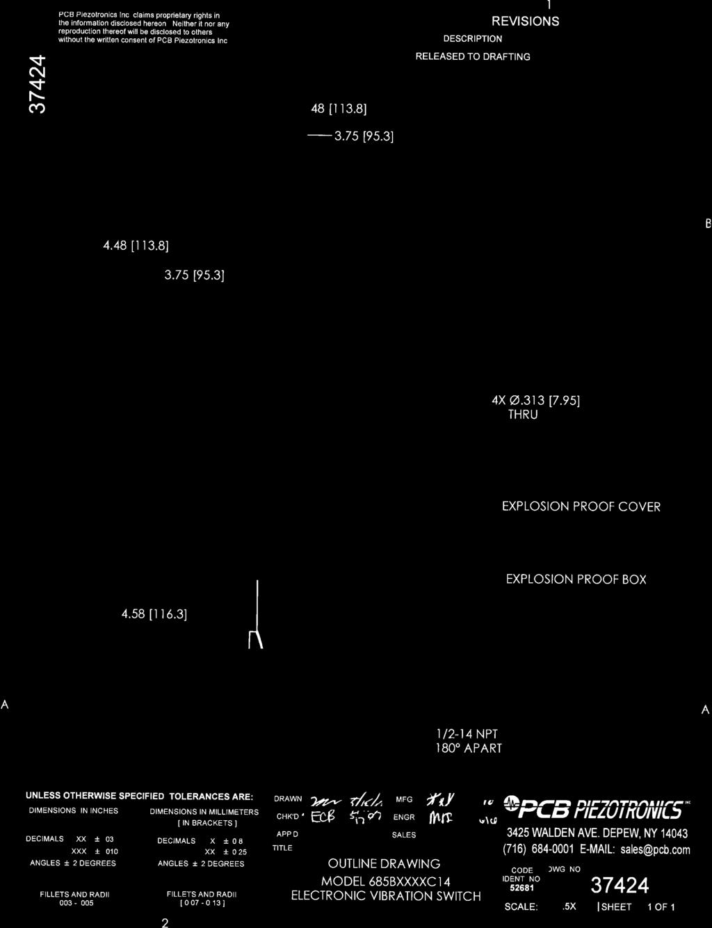
12 SENSORS AND INSTRUMENTATION FOR MACHINE CONDITION MONITORING Explosion Proof Model Dimension Drawing Inch (mm) WARNING AC and DC input signals and power supply voltages could be hazardous. DO NOT connect live wires to screw terminal plugs, and DO NOT insert, remove, or handle screw terminal plugs with live wires connected. PAGE 7
13 SENSORS AND INSTRUMENTATION FOR MACHINE CONDITION MONITORING Connector and Pinout Diagram The 685B-Series uses screw terminal connectors for all input and output connections. Strip off 0.3 (8mm) of insulation from the connection wire ends. Feed the wire through the access ports, and terminate the wire in the correct location. Once connected, tug lightly on the wire to confirm connection is secure. Pin Location Diagram- Models with Internal Accelerometer and Triac Relays Pin Category Description 1 + Power 2 AC Power - Power/Common 3 Earth Ground (Also connect to enclosure safety lug) 4 Main Terminal 1 Alarm Output 5 Main Terminal 2 6 Main Terminal 1 Alert Output 7 Main Terminal 2 8 N/A N/A 9 N/A 10 Common Raw Vibration Output 11 +Signal 12 Remote Reset Connection (Do not apply power) 13 Control Configurations Common Connection 14 Calibration Connection ma Current Output ma PAGE 8
14 SENSORS AND INSTRUMENTATION FOR MACHINE CONDITION MONITORING Pin Location Diagram- Models with Internal Accelerometer and Electromechanical Relays Pin Category Description 1 + Power 2 AC Power - Power/Common 3 Earth Ground (Also connect to enclosure safety lug) 4 Normally Closed (when dipswitch is in de-energized position) 5 Alarm Output Common connection 6 Normally Open (when dipswitch is in de-energized position) 7 Normally Closed (when dipswitch is in de-energized position) 8 Alert Output Common connection 9 Normally Open (when dipswitch is in de-energized position) 10 Common Raw Vibration Output 11 +Signal 12 Remote Reset Connection (Do not apply power) 13 Control Configurations Common Connection 14 Calibration Connection ma Current Output ma PAGE 9
15 SENSORS AND INSTRUMENTATION FOR MACHINE CONDITION MONITORING Pin Location Diagram- Models with External Accelerometer and Triac Relays When the external 100mV/g ICP sensor option is specified, an additional terminal block location is added to the 685B-Series. The external accelerometer is connected to +Sensor and Sensor positions as indicated in the above figure and on the product label locate inside the top cover. The cable shield to the accelerometer should be grounded as required by local codes as well as to limit RFI/EMI interference. Pin Category Description 1 + Power 2 AC Power - Power/Common 3 Earth Ground (Also connect to enclosure safety lug) 4 Main Terminal 1 Alarm Output 5 Main Terminal 2 6 Main Terminal 1 Alert Output 7 Main Terminal 2 8 N/A N/A 9 N/A 10 + Sensor Sensor Input & 11 - Sensor/Common Raw Vibration Output 12 +Signal 13 Remote Reset Connection (Do not apply power) 14 Control Configurations Common Connection 15 Calibration Connection ma Current Output ma PAGE 10
16 SENSORS AND INSTRUMENTATION FOR MACHINE CONDITION MONITORING Pin Location Diagram- Models with External Accelerometer and Electromechanical Relays When the external 100mV/g ICP Sensor option is specified, an additional terminal block location is added to the 685B-Series. The external accelerometer is connected to +Sensor and Sensor positions as indicated in the above figure and on the product label locate inside the top cover. The cable shield to the accelerometer should be grounded as required by local codes as well as to limit RFI/EMI interference. Pin Category Description 1 + Power 2 AC Power - Power/Common 3 Earth Ground (Also connect to enclosure safety lug) 4 Normally Closed (when dipswitch is in de-energized position) 5 Alarm Output Common connection 6 Normally Open (when dipswitch is in de-energized position) 7 Normally Closed (when dipswitch is in de-energized position) 8 Alert Output Common connection 9 Normally Open (when dipswitch is in de-energized position) 10 + Sensor Sensor Input & 11 - Sensor/Common Raw Vibration Output 12 +Signal 13 Remote Reset Connection (Do not apply power) 14 Control Configurations Common Connection 15 Calibration Connection ma Current Output ma PAGE 11
17 SENSORS AND INSTRUMENTATION FOR MACHINE CONDITION MONITORING Configuring the 685B-Series Internal Diagram- Models with Triac Relays The internal diagram displays the location of the control features for the triac versions of the 685B-Series. The alert and alarm set points are adjusted via the single turn potentiometers. The alarm relay is set using the first potentiometer, and the alert relay is set using the third. The alert relay trips when the set percentage of the alarm value is reached. Time delays for both functions are controlled using the second and fourth potentiometers. Alert and alarm relays can be reset remotely by using the RESET and COMM pins or by using the internal reset switch as seen on the upper right hand corner of the diagram. Using the dipswitches beneath the terminal connectors, relay operation can be selected to be either latch or continuous, and each relay can be separately configured to be normally open (de-energized) or normally closed (energized). There is also a dipswitch to activate the calibration mode for condition simulation during the setup process. This is explained in detail on page 13. PAGE 12
18 SENSORS AND INSTRUMENTATION FOR MACHINE CONDITION MONITORING Internal Diagram- Models with Electromechanical Relays The internal diagram displays the location of the control features for the relay versions of the 685B-Series. The alert and alarm set points are adjusted via the single turn potentiometers. The alarm relay is set using the first potentiometer, and the alert relay is set using the third. The alert relay trips when the set percentage of the alarm value is reached. Time delays for both functions are controlled using the second and fourth potentiometers. Alert and alarm relays can be reset remotely by using the RESET and COMM pins or by using the internal reset switch as seen on the upper right hand corner of the diagram. Using the first dipswitch beneath the terminal connectors, relay operation can be selected to be either latch or continuous. The second and third dipswitches set the alert and alarm relay configuration to be energized or deenergized. The diagram above indicates the contacts that are normally open and normally closed when the dip switch is set to de-energized. When the dipswitch is changed to energized, the normally open and normally closed contacts would be reversed. The fourth dipswitch is used to activate the calibration mode for condition simulation during the setup process. This is explained in detail on page 12. PAGE 13
19 SENSORS AND INSTRUMENTATION FOR MACHINE CONDITION MONITORING Using Calibration Mode The 685B-Series has the unique ability to be calibrated using a 4-20 ma simulator. (IMI Sensors model 699A05, see Accessories page) This allows for a much more accurate and quantifiable calibration versus manually attuning the switch. The following steps allow for simple calibration using this configuration. 1) Connect the 4-20 ma simulator signal across the COMM and CAL pins. 2) Turn the calibration dipswitch to on. This will disable the switch s ability to measure physical vibration. 3) Turn both time delay potentiometers to zero for calibration purposes. This can be adjusted to desired delay after calibration. 4) Assume that 4 ma equals zero vibration and 20 ma equals full scale vibration. Then calculate, in ma, the vibration level for which the alert and alarm switches should trip. 5) Using the 4-20 ma simulator, send the appropriate alarm signal based on the calculation in the previous step for the alarm signal. 6) Adjust the SP Alarm set point potentiometer to the point when the red Alarm LED illuminates. 7) Using the 4-20 ma simulator, repeat step 5 for the Alert signal. 8) Adjust the SP Alert set point potentiometer to the point where the yellow Alert LED illuminates. It is important to set the Alarm potentiometer first because the Alert signal acts as a percentage of the value set for Alarm. 9) Disconnect the 4-20 ma simulator. 10) Turn off the calibration dipswitch. ** Warning: To avoid damage, insure 685B-Series is under power prior to applying the 4-20mA signal from the simulator. ** Testing the Calibration Pushing the Test button inside the housing simulates full scale vibration and should illuminate both the alert and alarm LED s. This feature can be used to adjust time delays to the desired values. This can be accurately calculated using the Test button and a stopwatch. Connecting the Remote Reset The 685B-Series allows for remote reset when the switch is in latch mode via a short between the RESET and COMM pins. Connecting the Raw Vibration Output All models in the 685B-Series offer the option for obtaining accelerometer s raw vibration signal. Models with internal accelerometers output 100 mv/g. To obtain this signal using digital analyzer, turn the ICP power OFF at the digital analyzer input. Connect the analyzer to the RV OUTPUT and COMM pins with the common connection on the COMM pin and the signal connection on the RV OUTPUT pin. PAGE 14

20 SENSORS AND INSTRUMENTATION FOR MACHINE CONDITION MONITORING Optional Accessories Model 080A209 Adapter Plate To retrofit old style vibration switch bolt patterns PAGE 15

21 SENSORS AND INSTRUMENTATION FOR MACHINE CONDITION MONITORING Model 699A05 Portable 4-20 ma Calibrator Provides current output for 685B-Series testing, read-out and calibration purposes. Also receives and displays current signal from 4-20 ma proportional output from the 685B-Series. PAGE 16
22 SENSORS AND INSTRUMENTATION FOR MACHINE CONDITION MONITORING Warning 1 ESD sensitivity The power supply/signal conditioner should not be opened by anyone other than qualified service personnel. This product is intended for use by qualified personnel who recognize shock hazards and are familiar with the safety precautions required to avoid injury. Warning 2 ESD sensitivity This equipment is designed with user safety in mind; however, the protection provided by the equipment may be impaired if the equipment is used in a manner not specified by PCB Piezotronics, Inc. Caution 1 ESD sensitivity Cables can kill your equipment. High voltage electrostatic discharge (ESD) can damage electrical devices. Similar to a capacitor, a cable can hold a charge caused by triboelectric transfer, such as that which occurs in the following: Laying on and moving across a rug, Any movement through air, The action of rolling out a cable, and/or Contact with a non-grounded person. The PCB solution for product safety: Connect the cables only with the AC power off. Temporarily short the end of the cable before attaching it to any signal input or output. Caution 2 ESD sensitivity ESD considerations should be made prior to performing any internal adjustments on the equipment. Any piece of electronic equipment is vulnerable to ESD when opened for adjustments. Internal adjustments should therefore be done ONLY at an ESD-safe work area. Many products have ESD protection, but the level of protection may be exceeded by extremely high voltage. PAGE 17
23 SENSORS AND INSTRUMENTATION FOR MACHINE CONDITION MONITORING Ordering Information/ Model Matrix IMI Part Number: 685B A1 0 Basic Model Series 685B Sensor Option 0 Internal 100 mv/g ICP Sensor 1 External 100mV/g ICP Sensor 2 External 100 mv/g ICP Sensor (Low Frequency) 3 Internal 100 mv/g ICP Sensor (Low Frequency) 4 External 100mV/g ICP Sensor (Sensor Fault Detection) 5 External 100mV/g ICP Sensor (Sensor Fault Detection) Scale Factor in/sec peak g peak mils peak to peak displacement mils peak to peak displacement in/sec peak Power Required VAC, 50/60 Hz 1 24 VDC ±10% Relay Type (two provided) 0 Triac, 5A/245vac 1 Form C Relay (SPDT) 10A/245Vac 5A/30Vdc Enclosure Type/ Hazardous Area Approval A1 Basic enclosure, internal pushbutton for remote reset A2 Same as A1, plus external pushbutton for remote reset A3 Same as A1, plus acceleration signal through external BNC A4 Same as A1, plus A2 & A3 C1 Explosion Proof Enclosure (must select option 4 connection) Connection Interface 0 Dual openings, cord grips 1 Dual openings, ½ NPT conduit hubs 2 Single opening, cord grip 3 Single opening, ½ NPT conduit hub 4 Dual openings, ½ NPT conduit hubs (for C1 enclosures only) 5 Dual openings, cord grip on left, ½ NPT conduit hub on right 6 Dual openings, cord grip on right, ½ NPT conduit hub on left CSA Class I, Division 2 approval is supplied as standard for switches that are NOT using the C1 enclosure but are using all italicized options. PAGE 18

24 62912 REV. NR ECO /24/15

25 62912 REV. NR ECO /24/15

26 62912 REV. NR ECO /24/15

27 62912 REV. NR ECO /24/15

28 62912 REV. NR ECO /24/15

29 62912 REV. NR ECO /24/15

30 Model Number 685B0X01C14 ELECTRONIC VIBRATION SWITCH Performance ENGLISH SI Measurement Range 0 to 1.5 in/sec pk 0 to 38.1 mm/s pk [4] Measurement Range 0 to 5 g pk 0 to 49 m/s² pk [5] Measurement Range 0 to 15 mil pk - pk 0 to 381 µm pk - pk [6] Measurement Range 0 to 50 mil pk - pk 0 to 1.27 mm pk - pk [7] Measurement Range 0 to 3.0 in/sec pk 0 to 76.2 mm pk - pk [8] Frequency Range(± 3 db) 120 to 60,000 cpm 2 to 1000 Hz [9] Power On Delay 20 sec 20 sec [10] Relay(Alert) 10A/245 VAC or 5A/30 VDC 10A/245 VAC or 5A/30 VDC Relay(Alarm) 10A/245 VAC or 5A/30 VDC 10A/245 VAC or 5A/30 VDC Relay(Contacts) Latching / Non-Latching Latching / Non-Latching Relay(Contacts) Normally Open / Closed Normally Open / Closed Alarm Setpoint 10 to 100% of Vibration Range 10 to 100% of Vibration Range Alert Setpoint 10 to 100% of Alarm Setpoint 10 to 100% of Alarm Setpoint Delay(Alert) 0 to 45 sec 0 to 45 sec Delay(Alarm) 0 to 45 sec 0 to 45 sec Acceleration Output(± 10 %) 100 mv/g 10.2 mv/(m/s²) Control Interface Power LED Green Green Alarm LED Red Red Alert LED Yellow Yellow Set Point Adjustment Single Turn Potentiometer Single Turn Potentiometer Time Delay Adjustment Single Turn Potentiometer Single Turn Potentiometer Reset Function Momentary Pushbutton Switch Momentary Pushbutton Switch [1] Self Test Function Momentary Pushbutton Switch Momentary Pushbutton Switch Switch Mechanism Function Select NO/NC NO/NC Alarm/Alert Function Select Latch or Continuous Latch or Continuous Environmental Temperature Range(Operating) -13 to 158 F -25 to 70 C Temperature Range(Storage) -40 to 257 F -40 to 125 C Enclosure Rating NEMA 4 IP66 Hazardous Area Approval Class I Div 1 Groups B, C, D Class I Div 1 Groups B, C, D Hazardous Area Approval Class II Div 1 Groups E, F, G Class II Div 1 Groups E, F, G Hazardous Area Approval Class III Class III Hazardous Area Approval Ex d IIB+H2 T4 Ex d IIB+H2 T4 Electrical Power Required VAC 50/60 Hz <150mA VAC 50/60 Hz <150mA Current Consumption <150 ma <150 ma Output Current 4 to 20 ma 4 to 20 ma [2] External Calibration Input 4 to 20 ma 4 to 20 ma [3] Raw Vibration Output 100 mv/g 100 mv/g Physical Size (Width x Height x Depth) 4.48 in x 4.58 in x 4.48 in 114 mm x 116 mm x 114 mm Weight 4 lb 1.8 kg Mounting Torque(Base) 2 to 5 ft-lb 3 to 7 Nm Sensing Element(Internal) 100 mv/g ICP" Accelerometer 100 mv/g ICP" Accelerometer Housing Material Aluminum Alloy Aluminum Alloy Electrical Connector Screw Terminals Screw Terminals Enclosure Internal and Remote Reset Internal and Remote Reset Screw Terminal Wire Size AWG mm² Cable Input 1/2" -14 threaded NPT Female 1/2" -14 threaded NPT Female Mounting Hole Size 0.31 in 7.8 mm Revision: B ECN #: OPTIONAL VERSIONS Optional versions have identical specifications and accessories as listed for the standard model except where noted below. More than one option may be used. NOTES: [1] Reset can also be engaged via external connection to common [2] Current will fluctuate at frequencies below 5 Hz. [3] Active only during calibration mode [4] Measurement Range for 685B0001C14. [5] Measurement Range for 685B0101C14. [6] Measurement Range for 685B0201C14. [7] Measurement Range for 685B0301C14. [8] Measurement Range for 685B0401C14. [9] To obtain cpm (1000 Hz) frequency response, grease must be applied to all mechanical couplings. Otherwise, frequency response is limited to approximately cpm (500 Hz) [10] Factory Set [11] See PCB Declaration of Conformance PS051 for details. Entered: AP Engineer: gs Sales: HJB Approved: BAM Spec Number: Date: 2/28/2014 Date: 2/28/2014 Date: 2/28/2014 Date: 2/28/ [11] All specifications are at room temperature unless otherwise specified. In the interest of constant product improvement, we reserve the right to change specifications without notice. ICP is a registered trademark of PCB Group, Inc. IMI Sensors 3425 Walden Depew, NY UNITED STATES Phone: Fax: imi@pcb.com Web site:
31
 3 Numero de LCIE 10 ATEX 3065 3 EC type examination certificate number LCIE 10 ATEX 3065 4")
32 1 ATTESTATION D'EXAMEN C E DE T Y P E 1 E C T Y P E EXAMINATION C E R T I F I C A T E 2 Appareil ou systeme de protection destine a etre utiiise en atmospheres explosibles (Directive 94/9/CE) 2 Equipment or protective system intended for use in potentially explosive atmospheres (Directive 94/9/EC) 3 Numero de LCIE 10 ATEX EC type examination certificate number LCIE 10 ATEX Appareil ou systeme de protection : Interrupteur de vibrations Type : 685 series 4 Equipment or protective system : Vibration switches Type : 685 series 5 Adresse : 6 Adresse : d'examen GE de type IMI / PGB Piezotronics 3425 Walden Avenue, Depew, New York IMI / PCB Piezotronics 3425 Walden Avenue, Depew, New York 5 Address : USA 6 Address : USA IMI / PCB Piezotronics 3425 Walden Avenue, Depew, New York USA IMI / PCB Piezotronics 3425 Walden Avenue, Depew, New York USA 7 Cet appareil ou systeme de protection et ses variantes eventuelles acceptees sont decrits dans I'annexe de la presente attestation et dans les documents descriptifs cites en reference. 8 Le LCIE, organisme notifie sous la reference 0081 conformement a rarticle 9 de la directive 94/9/CE du Parlement europeen et du Conseil du 23 mars certifie que cet appareil ou systeme de protection est conforme aux exigences essentielles de securite et de sante pour la conception et la construction d'appareils et de systemes de protection destines a etre utilises en atmospheres explosibles, donnees dans I'annexe II de la directive. Les resultats des verifications et essais figurent dans le rapport confidentiel LCIE, notified body number 0081 in accordance with article 9 of the Directive 94/9/EC of the European Parliament and the Council of 23 March certifies that this equipment or protective system has been found to comply with the essential Health and Safety Requirements relating to the design and construction of equipment and protective systems intended for use in potentially explosive atmospheres, given in Annex II to the Directive. The examination and test results are recorded in confidential report 9 Le respect des exigences essentielles de securite et de sante est assure par la conformite a : - EN (2006), - EN (2007) Compliance with the Essential Health and Requirements has been assured by compliance with - EN (2006), - EN (2007) 7 This equipment or protective system and any acceptable variation thereto are specified in the schedule to this certificate and the documents therein referred to. Safety 10 Le signe X lorsqu'il est place a la suite du numero de I'attestation, indique que cet appareil ou systeme de protection est soumis aux conditions speciales pour une utilisation sure, mentionnees dans I'annexe de la presente attestation. If the sign X is placed after the certificate number, it indicates that the equipment or protective system is subject to special conditions for safe use specified in the schedule to this certificate. 11 Cette attestation d'examen CE de type concerne uniquement la conception et la construction de I'appareil ou du systeme de protection specifie, conformement a I'annexe III de la directive 94/9/CE. Des exigences suppiementaires de la directive sont applicables pour la fabrication et la fourniture de I'appareil ou du systeme de protection. Ces dernieres ne sont pas couvertes par la presente attestation. This EC type examination certificate relates only to the design and construction of this specified equipment or protective system in accordance with annex III to the directive 94/9/EC. Further requirements of the directive apply to the manufacturing process and supply of this equipment or protective system. These are not covered by this certificate. 12 Le marquage de I'appareil ou du systeme de protection doit comporter les informations detaillees au point 12 The marking of the equipment or protective system shall include information Fontenay-aux-Roses, le 20 juillet Seul le texte en peut engager la responsabilite du LCIE. Ce document ne peut etre The LCIE's liability applies only on the French text. This document may only be reproduced i 'Change Page 1 of 2 IILCE_typ_app - LCIE Laboratoire Central (lu ; I : 1 HP S des Industries Electriques Une societe de Bureau Veritas 60 Societe par Actions au capital RCS www
33 13 ANNEXE 13 S C H E D U L E 14 ATTESTATION D'EXAMEN C E DE T Y P E 14 E C T Y P E EXAMINATION C E R T I F I C A T E A T E X L C I E 10 A T E X 3065 DESCRIPTION D E L'APPAREIL O U DU S Y S T E M E DESCRIPTION O F EQUIPMENT O R D E P R O T E C T I V E S Y S T E M P R O T E C T I O N Interrupteur de vibrations Type : 685 series Vibration switches Type : 685 series Le materiel est compose d'une enveloppe metailique antideflagrante contenant une carte electronique. The apparatus is made of a metallic flameproof enclosure including an electronic board. Parametres specifiaues du ou des modes de protection concernes : Specific parameters of the Alimentation : - version AC : Vac, 50/60Hz, - version DC : 24Vdc Sortie relais : -245Vac, - 30Vdc, 5A Sortie TRIAC : 245Vac, 5Aac Power - version AC : Vac, 50/60Hz, - version DC : 24Vdc Relay output: -245Vac, - 30Vdc, 5A TRIAC output: 245Vac, 5Aac max max of protection concerned : max max Le doit etre : IMI ou PCB Piezotronics Adresse :... Type: (1) de fabrication :... Annee de fabrication :... + H2T4 LCIE 10 ATEX 3065 T amb : a+ AVERTISSEMENT-NE PAS OUVRIR SOUS TENSION (1) complete par le modele The marking shall be : IMI or PCB Piezotronics Address :... Type: (1) Serial Year of construction :... + H2T4 LCIE ATEX 3065 T amb : to + WARNING-DO NOT OPEN WHEN ENERGIZED (1) completed with the model L'appareii doit egalement comporter le marquage normalement prevu par les normes de construction qui le concerne. The equipment shall also bear the usual marking required by the manufacturing standards applying to such equipment. D O C U M E N T S 16 DESCRIPTIFS Dossier technique rev.nr du Ce document comprend 7 rubriques CONDITIONS S P E C I A L E S P O U R U N E pages). UTILISATION DESCRIPTIVE D O C U M E N T S Technical file rev NR dated This file includes 7 items (14 pages). 17 S P E C I A L CONDITIONS F O R S A F E U S E None. Neant. E X I G E N C E S E S S E N T I E L L E S D E S E C U R I T E E T D E 18 ESSENTIAL H E A L T H A N D S A F E T Y R E Q U I R E M E N T S S A N T E Covered by standards listed at 9. Couvertes par les normes listees au point 9. VERIFICATIONS E T ESSAIS INDIVIDUELS CONDITIONS D E ROUTINE VERIFICATIONS AND T E S T S None. Neant. CERTIFICATION Les detenteurs d'attestations d'examen CE de type doivent egalement satisfaire les exigences de controle de production telles que definies a I'article 8 de la directive 94/9/CE. 20 CONDITIONS O F CERTIFICATION Holders of EC type examination certificates are also required to comply with the production control requirements defined in article 8 of directive 94/9/EC. Seul le texte en peut engager la responsabilite du LCIE. Ce document ne peut etre reproduit que dans son integralite, sans aucune modification The LCIE's liability applies only on the French text. This document may only be reproduced in its entirety and without any change 01-Annexe Pags 2 OT 2 -
34 &'()* + #,#!"#$% "-.*/!+'(0!" #$# %&' (# #### )* (* + #,( ## # -#)* (* +.#.#, ##/. ## 0 ( $( ( ##1"#-1& ##.121& 2121&.# &.".,"9##. &.".,,9##. &."#"#,"9##" &.##:2,#;##.< &.##:2,";##:< &#"";##:< &."###,,9##" &."###,,9##. &."###,,9## &."###,,9## &."###,,.9##. &."###,,-9##" & &8 & &=( >3( 4) 0$,&3 & &=( >3( 4) 0$,&3 %> 0% '&? (+!"# $!!!%&!!!'! &' &!"!! ('&'& &! ' >(;%3<>=0=( & (6 )+,4( ( +> 3( & +6;&%< A,>=0 (6 >(( 0 & > ;&@7<1 (( 0 %6(( 0 (( 0 A@ ) >=0(6 >(( 0 &."###,,""9## 5 6% (( 0 &3A %> 0A '32# '32#. 7&8 4&"#7&8#. &?'&?B* ) & =;##-"< (1678*7505 0,?,A )*'! +!* %! ('&&!% %!! "#.#"11#"!
35 %6 9!"#!$!
36
37
38
39
Model 685B1001A10. Electronic Vibration Switch. Installation and Operating Manual
 Model 685B1001A10 Electronic Vibration Switch Installation and Operating Manual For assistance with the operation of this product, contact PCB Piezotronics, Inc. Toll-free: 800-959-4464 24-hour SensorLine:
Premium Desoldering station with Electric Pump Ref. DIS-D
 www.jbctools.com Premium Desoldering station with Electric Pump Ref. DIS-D Packing List The following items should be included: DI Control Unit... 1 unit Ref. DI-1D (120V) DI-2D (230V) DI-9D (100V) Electric
TECHNICAL PRODUCT DATASHEET
 ISO 9001 CERTIFIED Phone: (352) 629-5020 or 800-533-3569 Fax: (352)-629-2902 SUITABLE FOR EXTERNAL DISTRIBUTION ENFO IV P/N 108661 P/N 112600 (metric) P/N 112600-03 (metric, Chinese) PAGE 1 of 12 1. REVISION
Hot Air Station without Extractor desk Ref. JTSE-QA
 www.jbctools.com Hot Air Station without Extractor desk Ref. JTSE-QA Packing List The following items should be included: JTSE Control Unit...1 unit Ref. JTSE-1A (100V / 120V) JTSE-2A (230V) Stand...1
MicroCoat Flow Guard Operating Manual
 A NORDSON COMPANY MicroCoat Flow Guard Operating Manual MC480M Series Electronic pdf files of EFD manuals are also available at www.efd-inc.com/manuals.html Contents Introduction...3 Specifications...4
Living Space Sensor Touchscreen Covers SXWSCDXSELXX (Touchscreen Display) SXWSCDPSELXX (Touchscreen Display with Occupancy Sensor)
 SXWSCDPSELXX (Touchscreen Display with Occupancy Sensor)") schneider-electric.com 1 SmartX TM Living Space Sensor screen Covers SXWSCDXSELXX (screen Display) SXWSCDPSELXX (screen Display with Occupancy Sensor) Product Description SmartX sensors are a family of
schneider-electric.com 1 SmartX TM Living Space Sensor screen Covers SXWSCDXSELXX (screen Display) SXWSCDPSELXX (screen Display with Occupancy Sensor) Product Description SmartX sensors are a family of
EJX-A and EJA-E Series Differential Pressure and Pressure Transmitters
 EJX-A and EJA-E Series Differential Pressure and Pressure Transmitters Change No. 15-015 The following explosion protected types and marine certificate types are added for EJX-A and EJA-E series. Please
EJX-A and EJA-E Series Differential Pressure and Pressure Transmitters
 User s EJX-A and EJA-E Series Differential Pressure and Pressure Transmitters Change No. 15-015 The following explosion protected types and marine certificate types are added for EJX-A and EJA-E series.
EJX / EJA-E series. For the description on the applicable page of users manual as shown in the item 1, please use revised information as shown in 2.
 EJX / EJA-E series Change No. 15-013 For the description on the applicable page of users manual as shown in the item 1, please use revised information as shown in 2. 1. Applicable Users and Page IM No.
YVP110 Advanced Valve Positioner. Please use the attached sheets for the pages listed below in the following manuals. IM 21B04C01-01E (10th)
") User s Advanced Valve Positioner Change No. 15-006 Please use the attached sheets for the pages listed below in the following manuals. IM 21B04C01-01E (10th) Page and Item Page 1-3 1.8 EMC Conformity Standards
User s Advanced Valve Positioner Change No. 15-006 Please use the attached sheets for the pages listed below in the following manuals. IM 21B04C01-01E (10th) Page and Item Page 1-3 1.8 EMC Conformity Standards
MicroCoat Flow Guard. MC480M Series. Operating Manual. IMPORTANT! Save this Sheet. Forward to Maintenance or Tool Crib Supervisors
 MicroCoat Flow Guard Operating Manual MC480M Series IMPORTANT! Save this Sheet. Forward to Maintenance or Tool Crib Supervisors Electronic pdf files of EFD manuals are also available at www.nordsonefd.com
Micro800 Programmable Controller External AC Power Supply
 Installation Instructions Original Instructions Micro800 Programmable Controller External AC Power Supply Catalog Numbers 2080-PSAC-12W Topic Page Important User Information 2 Overview 7 Connect the Power
CWDM-1-8 / 9-16 CWDM-1-8-M / 9-16-M CWDM-1-8-L / CWDM-9-16-L
 CWDM-1-8 / 9-16 CWDM-1-8-M / 9-16-M CWDM-1-8-L / CWDM-9-16-L 9-channel CWDM multiplexer and demultiplexer / multi mode (-M) / -low-loss (-L) User manual Nevion Nordre Kullerød 1 3241 Sandefjord Norway
CWDM-18. User manual. 18 channel CWDM mux/demux. Rev. B. Nevion Nordre Kullerød Sandefjord Norway Tel: nevion.
 18 channel CWDM mux/demux User manual Nevion Nordre Kullerød 1 3241 Sandefjord Norway Tel: +47 33 48 99 99 nevion.com Nevion Support Nevion Europe P.O. Box 1020 3204 Sandefjord, Norway Support phone 1:
Intrinsically Safe, NEMA 4, Type 4X, IP67 Loop-Powered Meter
 PD685 Intrinsically Safe, NEMA 4, Type 4X, IP67 Loop-Powered Meter Actual Size Digits C US Intrinsically Safe 3½ Digits LARGE DISPLAY NEMA 4, Type 4X, IP67 Loop-Powered Field-Mount Process Meter 4-20 ma
Wideband Optical Couplers
 Flashlink User Manual WOC-2-50-50 WOC-2-90-10 WOC-2-95-05 WOC-4-25 Wideband Optical Couplers network-electronics.com Rev. 3 Network Electronics ASA Thorøya P.O. Box 1020 N-3204 Sandefjord, Norway Phone:
vibration switch
 user manual 440-450 vibration switch INSTALLATION - OPERATION - MAINTENANCE Z0592822_A ISSUED 06/2017 READ AND UNDERSTAND THIS MANUAL PRIOR TO OPERATING OR SERVICING THIS PRODUCT. contents Section 1 -
Iron Man Plus Workstation Monitor, Installation, Operation and Maintenance USER GUIDE TB Features and Components. Description.
 USER GUIDE TB-9022 Iron Man Plus Workstation Monitor Installation, Operation and Maintenance Features and Components Made in the United States of America A B C D Figure 1. Iron Man Plus Workstation Monitor
Certificate of Compliance
 Certificate of Compliance Certificate: 70067850 Date Issued: July 28, 2017 Issued to: Otis Instruments, Incorporated 301 S. Texas Ave. Bryan, Texas, 77803 USA Attention: Nicholas Sandera The products listed
DTM Distributed Transmitter-Monitor
 DTM Distributed Transmitter-Monitor DTM10 Proximity Distributed Transmitter-Monitor (Shaft Vibration, Thrust Position and Speed) The DTM10 distributed vibration transmitter-monitor is ideal for monitoring
Rosemount 0085 Pipe Clamp Sensor Assembly. Quick Start Guide , Rev CA June 2016
 Rosemount 0085 Pipe Clamp Sensor Assembly 00825-0100-4952, Rev CA NOTICE This guide provides basic guidelines for Rosemount 0085 Pipe Clamp Sensor. It does not provide instructions for configuration, diagnostics,
INSTRUCTION MANUAL. D1xB2XH2 Xenon Beacon For use in Hazardous Locations. 2) Rating & Marking Information
 Rating & Marking Information") INSTRUCTION MANUAL D1xB2XH2 Xenon Beacon For use in Hazardous Locations 2) Rating & Marking Information 2.1 Public Mode Fire Alarm Ratings The D1xB2XH2 is certified for use as public mode visual alarm
INSTRUCTION MANUAL D1xB2XH2 Xenon Beacon For use in Hazardous Locations 2) Rating & Marking Information 2.1 Public Mode Fire Alarm Ratings The D1xB2XH2 is certified for use as public mode visual alarm
INSTRUCTION MANUAL. D1xB2XH1 Xenon Beacon For use in Hazardous Locations. 2) Rating & Marking Information
 Rating & Marking Information") INSTRUCTION MANUAL D1xB2XH1 Xenon Beacon For use in Hazardous Locations 2) Rating & Marking Information 2.1 Public Mode Fire Alarm Ratings The D1xB2XH1 is certified for use as public mode visual alarm
INSTRUCTION MANUAL D1xB2XH1 Xenon Beacon For use in Hazardous Locations 2) Rating & Marking Information 2.1 Public Mode Fire Alarm Ratings The D1xB2XH1 is certified for use as public mode visual alarm
SEL-3422 Motor Relay HMI Quick-Start Guide
 SEL-3422 Motor Relay HMI Quick-Start Guide Overview The SEL-3422 Motor Relay HMI indicates the SEL-849 operation status through the ten LEDs on its front panel. Eight of these LEDs are programmable. The
Q-SERIES DI WATER HEATER
 Phone: 800-669-1303 or 801-561-0303 Fax: 801-255-2312 e-mail: treborservice@idexcorp.com Q-SERIES DI WATER HEATER Operation / Maintenance Manual SERIAL NUMBER: PATENTS: U.S. 5971402, U.S. 6433319, U.S.
Certificate of Compliance
 FF0 001 Certificate of Compliance Certificate: 70116279 (LR 025993_0_000) Issued to: General Monitors, Incorporated 26776 Simpatica Circle Lake Forest, California 92630 USA Attention: Larry Vlagea The
GETTING STARTED GUIDE NI NI-XNET Hardware Selectable Interface. Français Deutsch 日本語한국어简体中文. ni.com/manuals
 GETTING STARTED GUIDE NI 9860 NI-XNET Hardware Selectable Interface Français Deutsch 日本語한국어简体中文 ni.com/manuals This document explains how to connect to the NI 9860. Note Before you begin, complete the
Product ID. General. TE CONNECTIVITY SENSORS /// EXxxHyy Ex-Atex & NA 09/2017 Page 1
 s for use in explosive atmospheres Europe ATEX II 2 G and North America ClI, Div 1 & 2 and Cl II, Div 1 & 2 and Cl III and North America Cl I, Zone 1 Product ID Type # Product # Drawing # EX34H 385Z-05637
Druck DPI 705/DPI 705 IS Series
 GE Sensing & Inspection Technologies 99 Washington Street Melrose, MA 02176 Phone 781-665-1400 Toll Free 1-800-517-8431 Visit us at www.testequipmentdepot.com Druck DPI 705/DPI 705 IS Series Digital Pressure
PQS performance specification
 PQS performance specification WHO/PQS/E06/TR04.1 Original: English Distribution: General TITLE: Wall-mounted pen recording thermometer Specification reference: E06/TR04.1 Product verification protocol:
Certification Supplement Manual
 PROCESS ANALYSERS SERVOTOUGH Oxy Gas Analyser Certification Supplement Manual Part Number: 01910008B Revision: 9 Language: UK English This page intentionally blank SERVOTOUGH Oxy Certification Supplement
Certificate of Compliance
 FF0 001 Certificate of Compliance Certificate: 70116284 (LR 064969_0_00) Issued to: Mine Safety Appliances Company North American Division 1000 Cranberry Woods Dr Cranberry Township, Pennsylvania 16066-5296
Model OEM-2 INSTRUCTIONS FOR USE
 ECO SENSORS, INC. 3-03.2 OEM OZONE CONTROLLER Model OEM-2 INSTRUCTIONS FOR USE GENERAL The model OEM-2 is a system to control ozone generators and alarms based on an adjustable ozone concentration set
MultiTemp IV Thermostatic Circulator
 GE Healthcare Life Sciences MultiTemp IV Thermostatic Circulator Operating Instructions Original instructions Table of Contents Table of Contents 1 Introduction... 1.1 About this operating instructions...
DIGITAL METERS Large Display Temperature Meters Instruction Manual
 DIGITAL METERS Large Display Temperature Meters PD755 PD756 PD757 Handles Thermocouple & RTD Inputs with Simplicity J, K, T, E, R, & S Thermocouples 100 Ω Platinum RTD (0.00385 or 0.00392 curve) Large
Dual SDI Optical to Electrical Converter
 Flashlink User Manual SDI-OE-2 Dual SDI Optical to Electrical Converter network-electronics.com Rev. 3 Network Electronics ASA Thorøya P.O. Box 1020 Sandefjord, Norway Phone: +47 33 48 99 99 Fax: +47 33
Certificate of Compliance
 Certificate of Compliance Certificate: 1238566 Issued to: Rosemount Analytical Inc. Solon Research & Development Ctr 6565-P Davis Industrial Pkwy Solon, OH 44139 USA Attention: Dana Crowley The products
Certificate of Compliance
 FF0002 Certificate of Compliance Certificate: 70044220 Issued to: Cascade Technologies Limited Glendevon House Castle Business Park Stirling FK9 4TZ UK Attention: Mr. Marcus Douglas The products listed
Explosion Proof Push Button Momentary Switch - C1D1, C2D1 - Adjustable Timer - 10 sec-170 Minutes
 Explosion Proof Push Button Momentary Switch - C1D1, C2D1 - Adjustable Timer - 10 sec-170 Minutes Part #: EPS-PB10-MS-AT-V3 Made in the USA The Larson Electronics EPS-PB10-MS-AT-V2 Explosion Proof Push
Stopper Station Series SS-2008 Push Button Pneumatic Timer Button
 Stopper Station Series SS-2008 Push Button Pneumatic Timer Button ADA for operation Pneumatic Timer Models SS-2008 Red SS-2108 Green SS-2208 Yellow SS-2308 White SS-2408 Blue ALL MODELS COME WITH A COLOR
Oxygen (O2) Single-Point Gas Detection System
 Single-Point Gas Detection System") Oxygen (O) Single-Point Gas Detection System DESCRIPTION Wall-mounted gas monitor with built-in oxygen (O) sensor, accepts one analog remote device such as a secondary gas sensor, temperature or humidity
Oxygen (O) Single-Point Gas Detection System DESCRIPTION Wall-mounted gas monitor with built-in oxygen (O) sensor, accepts one analog remote device such as a secondary gas sensor, temperature or humidity
GG-EM ENTRANCE MONITOR. Installation and Operation Manual
 GG-EM ENTRANCE MONITOR Installation and Operation Manual 2 GG-EM Warning Use this product only in the manner described in this manual. If the equipment is used in a manner not specified by Calibration
Concerning the use of GP4000 Series Graphic Operator Interface for applications in potentially explosive atmospheres (Zones 2/22)
") GP4000 Series ATEX Instruction Guide www.pro-face.com Concerning the use of GP4000 Series Graphic Operator Interface for applications in potentially explosive atmospheres (Zones 2/22) Digital Electronics
GP4000 Series ATEX Instruction Guide www.pro-face.com Concerning the use of GP4000 Series Graphic Operator Interface for applications in potentially explosive atmospheres (Zones 2/22) Digital Electronics
Rosemount 214C Sensor. Quick Start Guide , Rev AF August 2017
 Rosemount 214C Sensor 00825-0400-2654, Rev AF NOTICE This guide provides basic guidelines for Rosemount 214C Sensor models. If the sensor was ordered assembled to a temperature thermowell or transmitter,
Operating Instructions
 Operating Instructions ProVicom MT-65, MT-125 R. STAHL HMI Systems GMBH Im Gewerbegebiet Pesch 14 50767 Köln Version 1.7 Issue: 21.07.2008 R. STAHL HMI Systems GmbH / OperatingInstruction_Provicom_Falcon_en_1_7.doc
Ex SOLENOID / ALARM DRIVER. PRepower 5203B. Table of contents. Applications Safety instructions Technical characteristics...
 14 Ex SOLENOID / ALARM DRIVER PRepower 5203B Table of contents Warnings... 16 Safety instructions... 17 Declaration of Conformity... 19 How to dismantle SYSTEM 5000... 20 Application... 21 Technical characteristics...
Models LBW-420-LEL (24 VDC powered) Ammonia Leak Detector
 Ammonia Leak Detector") Models LBW-420-LEL (24 VDC powered) Ammonia Leak Detector CAUTION & SYMBOL DEFINITIONS: CAUTION: Gives detailed description of different situations to avoid or not avoid for the proper operation of the
Models LBW-420-LEL (24 VDC powered) Ammonia Leak Detector CAUTION & SYMBOL DEFINITIONS: CAUTION: Gives detailed description of different situations to avoid or not avoid for the proper operation of the
PQS performance specification
 PQS performance specification WHO/PQS/E006/TH06.2 Original: English Distribution: General TITLE: Integrated electronic thermometer, with or without alarm function, for vaccine refrigerators and freezers
ETH1000-MKII. User manual
 ETH1000-MKII Gigabit Ethernet Media Converter User manual Rev. 1 1 Nevion Support Nevion Europe P.O. Box 1020 3204 Sandefjord, Norway Support phone 1: +47 33 48 99 97 Support phone 2: +47 90 60 99 99 Nevion
Instruction Manual WARNING
 Controllers Instruction Manual WARNING THIS MANAUL MUST BE CAREFULLY READ BY ALL INDIVIDUALS WHO HAVE OR WILL HAVE THE RESPONSIBILITY FOR INSTALLING, USING OR SERVICING THIS PRODUCT. Like any piece of
MODEL FPT-130 SINGLE POINT FREEZE PROTECTION HEAT TRACE CONTROL
 TRACON MODEL FPT-130 SINGLE POINT FREEZE PROTECTION HEAT TRACE CONTROL TABLE OF CONTENTS FPT 130 Overview... 2 Installation... 3 Power Source and Load Connections... 4 Temperature Sensor... 5 External
INSTRUCTION & SERVICE MANUAL D1xS1 & D1xS2 ALARM HORNS For Use In Hazardous Locations - Gas
 INSTRUCTION & SERVICE MANUAL D1xS1 & D1xS2 ALARM HORNS For Use In Hazardous Locations - Gas UL 1203 CSA C22.2 NO. 30-M1986 The D1xS1 and D1xS2 Alarm Horns also comply with the following standards for signaling
Test Report. Appliance EMF Testing
 Project: 11014506A Date: November 6, 2015 Model: 120V_WWF13NW Test Report On Appliance EMF Testing Copyright 2005 UL LLC UL LLC authorizes the above-named company to reproduce this Report provided it is
Certificate of Compliance
 FF0002 Certificate of Compliance Issued to: Exheat Ltd. Threxton Road Industrial Estate Watton Thetford Norfolk, IP25 6NG UNITED KINGDOM Attention: James Pettman The products listed below are eligible
Nitrogen Dioxide (NO2) Single-Point Gas Detection System
 Single-Point Gas Detection System") Nitrogen Dioxide (NO) Single-Point Gas Detection System DESCRIPTION Wall-mounted gas monitor with built-in nitrogen dioxide (NO)/diesel fume gas sensor, accepts one analog remote device such as a secondary
Nitrogen Dioxide (NO) Single-Point Gas Detection System DESCRIPTION Wall-mounted gas monitor with built-in nitrogen dioxide (NO)/diesel fume gas sensor, accepts one analog remote device such as a secondary
Report No EC. 1 Windsor Dials, Windsor, Berkshire, UK. SL4 1RS ATEX CERTIFICATION REPORT. Electronstandart-pribor
 Report No. 3040249EC FM Approvals Ltd 1 Windsor Dials, Windsor, Berkshire, UK. SL4 1RS ATEX CERTIFICATION REPORT Product: Model and/or Type Reference: Flame Detector IPES-IR3 Description of the Product:
Two-Channel Gas Controller
 Two-Channel Gas Controller Specifications subject to change without notice. USA 09 Page of DESCRIPTION Highly configurable, UL 0 performance-tested and -certified, and wall-mounted gas monitor; continuously
Dräger Polytron 5100 EC Detection of toxic gases and vapors
 Dräger Polytron 5100 EC Detection of toxic gases and vapors The Dräger Polytron 5100 EC is a cost-effective explosion proof transmitter for the detection of toxic gases or oxygen. It uses a high performance
Single Point Freeze Protection Heat Trace Control TRACON MODEL FPT 130 Installation and Operation Manual
 We manage heat MANUAL Single Point Freeze Protection Heat Trace Control TRACON MODEL FPT 130 Installation and Operation Manual 1850 N Sheridan Street South Bend, Indiana 46628 (574) 233-1202 or (800) 234-4239
MW Pince courant de fuite Leakage current Clampmeter. Notice d utilisation User s Manual M3950M00
 MW 3950 Pince courant de fuite Leakage current Clampmeter Notice d utilisation User s Manual M3950M00 Safety Information To ensure safe operation and service of the Tester, follow these instructions. Failure
Controllers. Instruction Manual WARNING
 Controllers Instruction Manual WARNING THIS MANUAL MUST BE CAREFULLY READ BY ALL INDIVIDUALS WHO HAVE OR WILL HAVE THE RESPONSIBILITY FOR INSTALLING, USING OR SERVICING THIS PRODUCT. Like any piece of
ETH1000-D. User manual
 ETH1000-D Gigabit Ethernet Media Converter with DWDM laser User manual Rev. 2 Nevion Europe P.O. Box 1020, 3204 Sandefjord, Norway Tel: +47 33 48 99 99 Fax: +47 33 48 99 98 www. Nevion Support Nevion Europe
Installation Guide (English) for other languages see
 for other languages see") Installation Guide (English) for other languages see www.axis.com Liability Every care has been taken in the preparation of this document. Please inform your local Axis office of any inaccuracies or omissions.
Installation Guide (English) for other languages see www.axis.com Liability Every care has been taken in the preparation of this document. Please inform your local Axis office of any inaccuracies or omissions.
Ramsey Motion Monitoring Systems
 Ramsey Motion Monitoring Systems 60-200 Motion Monitoring Accurate Sensing of Underspeed, Overspeed and Zero Speed Conditions on Rotating Shafts and Machinery The Ramsey Series 60-200 Motion Monitoring
3M Benchtop Air Ionizer 963E. User s Guide
 3M Benchtop Air Ionizer 963E User s Guide 1 Table of Contents Section Page Safety Information...3 1. Description...4 2. Performance...4 3. Power Requirements...4 4. Installation...4 5. Operation...5 6.
Emotron M10 Shaft Power Monitor. Instruction manual English
 Emotron M10 Shaft Power Monitor Instruction manual English Contents 1 Inside the box... 3 2 Safety... 4 3 Description... 5 4 Getting Started... 6 4.1 Please take note of the safety section... 6 4.2 Connection
Rosemount 148 Temperature Transmitter. Quick Start Guide , Rev GA September 2016
 Rosemount 148 Temperature Transmitter 00825-0100-4148, Rev GA NOTICE This guide provides basic guidelines for the Rosemount 148. It does not provide instructions for detailed configuration, diagnostics,
INSTRUCTION MANUAL (ATEX / IECEx)
") INSTRUCTION MANUAL (ATEX / IECEx) BExS110D and BExS110D-R Sounder For use in Flammable Gas and Dust Atmospheres BExS110D BExS110D-R 1) Warnings DO NOT OPEN WHEN AN EXPLOSIVE ATMOSPHERE IS PRESENT DO NOT
INSTRUCTION MANUAL (ATEX / IECEx) BExS110D and BExS110D-R Sounder For use in Flammable Gas and Dust Atmospheres BExS110D BExS110D-R 1) Warnings DO NOT OPEN WHEN AN EXPLOSIVE ATMOSPHERE IS PRESENT DO NOT
User Guide. Luxxor. 35 LED Light Source Fax: Tremont Street, Rochester, New York gradientlens.
 User Guide Luxxor 35 LED Light Source 207 Tremont Street, Rochester, New York 14608 800.536.0790 Fax: 585.235.6645 REV. 0116 gradientlens.com warnings & cautions Warnings & Cautions PORTABLE CAMERA Luxxor
INSTRUCTION & SERVICE MANUAL
 INSTRUCTION & SERVICE MANUAL D1xC COMBINED RADIAL HORNS & STROBES For Use In Hazardous Locations - Gas 3) Ratings and Markings The D1xC1 and D1xC2 combined alarm horns and strobes comply with the following
Dräger Polytron 5200 CAT Detection of flammable gases and vapours
 Dräger Polytron 5200 CAT Detection of flammable gases and vapours The Dräger Polytron 5200 CAT is a cost-effective explosion-proof transmitter for the detection of flammable gases in the lower explosion
Dräger Polytron 5700 IR Detection of flammable gases and vapours
 Dräger Polytron 5700 IR Detection of flammable gases and vapours The Dräger Polytron 5700 IR is a cost effective explosion-proof transmitter for the detection of flammable gases in the lower explosive
High Pressure Conductivity Monitor
 Product Data Sheet PDS 71-EDS880/1/rev.A August 2006 Model EDS880/1 High Pressure Conductivity Monitor COMPLETE SYSTEM FOR THE DETERMINATION OF CONDUCTIVITY IN HIGH PRESSURE SYSTEMS SENSOR INSTALLS DIRECTLY
Quick Start Guide , Rev EA December Rosemount 0065/0185 Sensor Assembly
 Quick Start Guide 00825-0200-2654, Rev EA Rosemount 0065/0185 Sensor Assembly Quick Start Guide NOTICE This guide provides basic guidelines for Rosemount 0065 and 0185 Sensor models. It does not provide
CONTROL BE MADE CHANGES MAY NOT. Page 1
 HI 6020IT and HI 6020JB US & Canada Hazardous Locations User Guide (Class I, II, III, Division 1, Class I, Zone 0 and Zone 20) Hardy Process Solutions Document Number: : 0596-0352-01 REV A CONTROL LLED
Michael J. Caron, Test Engineer. Lee R. Senne, Test Technician. Kent L. Erickson, Dynamics Division Manager
 Engineering Report 49820-1 Vibration Test for Crystal Group Inc. Prepared by Michael J. Caron, Test Engineer Lee R. Senne, Test Technician Approved by Kent L. Erickson, Dynamics Division Manager This document
Capital Controls SERIES 70CV3000 CHLOROMATIC VALVE
 Capital Controls SERIES 70CV3000 CHLOROMATIC VALVE Integrated Gas Control Valve with Integral Controller The Series 70CV3000 Chloromatic Intelligent Gas Flow Control Valve is designed to control chemical
Installation and Operating Instructions
 The Leader of RF and Sonic Level For Assistance Call 1-800-527-6297 Outside North America 1-215-674-1234 Installation and Operating Instructions Series 504-1200 Ultrasonic VeriGAP Switch using 404-1200
ChemScan mini Analyzer for Low Ammonia Monitoring Installation, Operation and Maintenance Manual
 ChemScan mini Analyzer for Low Ammonia Monitoring Installation, Operation and Maintenance Manual asaanalytics.com ChemScan mini Low Ammonia Analyzer O&M Manual - Rev 223K TABLE OF CONTENTS ANALYZER DESCRIPTION
AB Parts. ControlNet Coax Tap. Installation Instructions. (Cat. Nos TPR, -TPS, -TPYR, -TPYS) What s in This Document
 What s in This Document") Installation Instructions ControlNet Coax Tap (Cat. Nos. 1786-TPR, -TPS, -TPYR, -TPYS) What s in This Document Use this document as a guide when installing a ControlNet coax tap. To: See Page: verify package
Installation Instructions ControlNet Coax Tap (Cat. Nos. 1786-TPR, -TPS, -TPYR, -TPYS) What s in This Document Use this document as a guide when installing a ControlNet coax tap. To: See Page: verify package
Tokyo Gas Engineering Solutions Corporation
 Laser Methane mini SA3C32A Operation Manual Read this manual before using the equipment. Keep this manual with the equipment. Tokyo Gas Engineering Solutions Corporation For Safety Prior to using this
Operating Manual MS220DA
 ZIEHL industrie elektronik GmbH + Co KG Daimlerstraße 13, D 74523 Schwäbisch Hall + 49 791 504-0, info@ziehl.de, www.ziehl.de Temperature Relays and MINIKA Mains Monitoring Digital Panel Meters MINIPAN
CAUTION & SYMBOL DEFINITIONS:
 1441 Rice Street, St. Paul, MN 55117-3899 USA Phone (651) 487-8844 Fax (651) 487-8857 info@coolairinc.com www.coolairinc.com CAUTION & SYMBOL DEFINITIONS: LBW-50 SPECIFICATIONS (cont d) CAUTION: Gives
DEB71. Earth Leakage Monitoring Relay. Benefits. Description
 Earth Leakage Monitoring Relay Benefits Adjustable trip level. Adjustable leakage threshold from 30mA to 5A or from 300mA to 30A. 2 outputs. Two relay outputs provide, besides the alarm signal an additional
SEC Signature Process Gas Analyzer
 SEC Signature Process Gas Analyzer Instruction and Operation Manual Sensor Electronics Corporation 5500 Lincoln Drive Minneapolis, Minnesota 55436 USA (952) 938-9486 Fax (952) 938-9617 email sensor@minn.net
1022 R/T Remote Monitor
 1022 R/T Remote Monitor INSTRUCTIONS AMC-1022R/T WITH REMOTE SENSOR OR TRANSMITTER INSTALLATION AND OPERATING INSTRUCTIONS FOR THE AMC-1022R/T UNIT IMPORTANT: Please read these installation and operating
MODEL GPT-130 SINGLE POINT HEAT TRACE CONTROL THERMOSTAT
 TRACON MODEL GPT-130 SINGLE POINT HEAT TRACE CONTROL THERMOSTAT TABLE OF CONTENTS GPT 130 Overview... 2 Installation... 3 Power Source and Load Connection... 4 Temperature Sensor Installation... 5 Panel
Installation Instructions
 Installation Instructions (Cat. No. 1794-OB16) 3 7 1 English 2 6 4 5 Module Installation This module mounts on a 1794 terminal base unit. 1. Rotate keyswitch (1) on terminal base unit (2) clockwise to
POINT I/O Field Potential Distributor Module
 Installation Instructions POINT I/O Field Potential Distributor Module Catalog Number 1734-FPD, Series B Inside... For See Page Important User Information 2 Environment and Enclosure 3 Preventing Electrostatic
Freeze Protection Thermostat TRACON MODEL GPT 3 Installation and Operation Manual
 MANUAL We manage heat Freeze Protection Thermostat TRACON MODEL GPT 3 Installation and Operation Manual Environmental Technology, Inc. 1850 N Sheridan Street South Bend, Indiana 46628 http://www.networketi.com/
standards: standards:
 INSTRUCTION MANUAL D2xB1LD2 LED Beacons For use in Hazardous Locations 1) Warnings DO NOT OPEN WHEN AN EXPLOSIVE ATMOSPHERE IS PRESENT DO NOT OPEN WHEN ENERGISED POTENTIAL ELECTROSTATIC CHARGING HAZARD
Record of Amendments. Version Date Amendment Section/page affected
 Industry support for effective compliance BTHA Guidance on The Restriction Of The Use Of Certain Hazardous Substances In Electrical and Electronic Equipment (recast) (RoHS) Directive 2011/65/EU Comparison
Rosemount 3490 Series 4 20 ma + HART Compatible Controller
 00825-0200-4841, Rev AB Rosemount 3490 Series 4 20 ma + HART Compatible Controller Failure to follow safe installation guidelines could result in death or serious injury The Rosemount 3490 Series Control
AM54. Armored Variable Area Flowmeter Series AM54331/32 Series AM54371/72/73/74 Series AM54431/32 Series AM54471/72/73/74
 AM54 Instruction Bulletin North American Installation Addendum Document Number PN25016 Armored Variable Area Flowmeter Series AM54331/32 Series AM54371/72/73/74 Series AM54431/32 Series AM54471/72/73/74
CA 134. Piezoelectric accelerometer. IECEx NEPSI TIIS KGS. » From the Vibro-Meter product line» Vibration monitoring over a wide temperature
 FEATURES» From the Vibro-Meter product line» Vibration monitoring over a wide temperature range, including cryogenic temperatures» Differential output» Hermetically welded» Certified for use in potentially
Thermal Management Products & Accessories for Enclosures
 Thermal Management Products & Accessories for Enclosures Photo: STEGO International Headquarters in Germany STEGO, Inc. 1395 S. Marietta Parkway Building 800 Marietta, GA 30067 Tel: (770) 984-0858 Fax:
Operation and Maintenance Manual
 Operation and Maintenance Manual GDS-48 Remote Bridge Sensor for Combustible Gases AUTHORIZED DISTRIBUTOR: GasDetectorsUSA.com - Houston, Texas USA sales@gasdetectorsusa.com - 832-615-3588 CAUTION: FOR
INSTRUCTION & SERVICE MANUAL
 INSTRUCTION & SERVICE MANUAL D2xC1 ALARM HORN AND STROBE For Use In Hazardous Locations 3) Ratings and Markings 3.1 ATEX / IECEx certification The D2xC1 Alarm Horn and Strobe complies with the following
WIO200 Water in oil sensor
 WIO200 Water in oil sensor User manual Rev. 1.15 Dato: 2011-11-03 Page 1 of 24 TABLE OF CONTENTS Table of contents... 2 Introduction... 3 Safety Advice... 4 Function... 6 Normal operation... 7 Failure
Fisher LCP100 Local Control Panel
 Instruction Manual LCP100 Local Control Panel Fisher LCP100 Local Control Panel Contents Introduction... 1 Scope of Manual... 1 Description... 2 Specifications... 2 Installation... 3 Hazardous Area Classifications