SLATE. Burner Control Module INSTALLATION INSTRUCTIONS R8001B2001
|
|
|
- Erik Skinner
- 5 years ago
- Views:
Transcription

1 SLATE Burner Control Module R8001B2001 INSTALLATION INSTRUCTIONS


2 Scan for more information
3 Application SLATE brings configurable safety and programmable logic together into one single platform. The platform can easily be customized for almost any requirement or application offering virtually limitless development opportunities with far less complexity. The R8001B2001 Burner Control module provides flame safeguard controls for a variety of applications within the SLATE system. It can be configured as a primary or programmer, semiautomatic or fully automatic. Features Provides 24 VDC or 24 to 240 VAC flame safeguard Valve proving Parameters and behaviors that allow emulation of 7800 and SOLA Series flame safeguards Dual fuels capability Configurable safety Safety relay Specifications Electrical Ratings: Voltage and Frequency: 24 VDC (± 15%), 24 VAC (± 15%), 50/60 Hz, VAC, 50/60 Hz Maximum Total Connected Load: 2000 VA Fusing Total Connected Load: 15A Fast Blow, type SC or equivalent SLATE BURNER CONTROL MODULE 3 R8001B2001
4 Environmental Ratings Ambient Temperature: Operating: -20 F to +150 F (-29 C to +66 C). Shipping: -40 F to +150 F (-40 C to +66 C). Humidity: 95% continuous, noncondensing. Vibration: 0.5G environment Dimensions: See Fig. 1 Weight: 1 lb 1 oz (0.48 Kg) Approvals Underwriters Laboratories Inc. Listed, File: MP268 Factory Mutual IRI Acceptable Federal Communications Commission: Part 15, Class A Must be mounted inside a grounded metal enclosure. Mounting DIN Rail (See Fig. 2) Required Components R8001A1001 SLATE Base Controller R8001S9001 SLATE Sub-Base Module
5 7-3/32 (181) 2-11/16 (68) Fig. 1. Dimensions in in. (mm). 4-19/32 (117) M35382 Principal Technical Features The R8001B2001 SLATE Burner Control module provides the SLATE combustion system with flame safeguard capability. SLATE BURNER CONTROL MODULE 5 R8001B2001
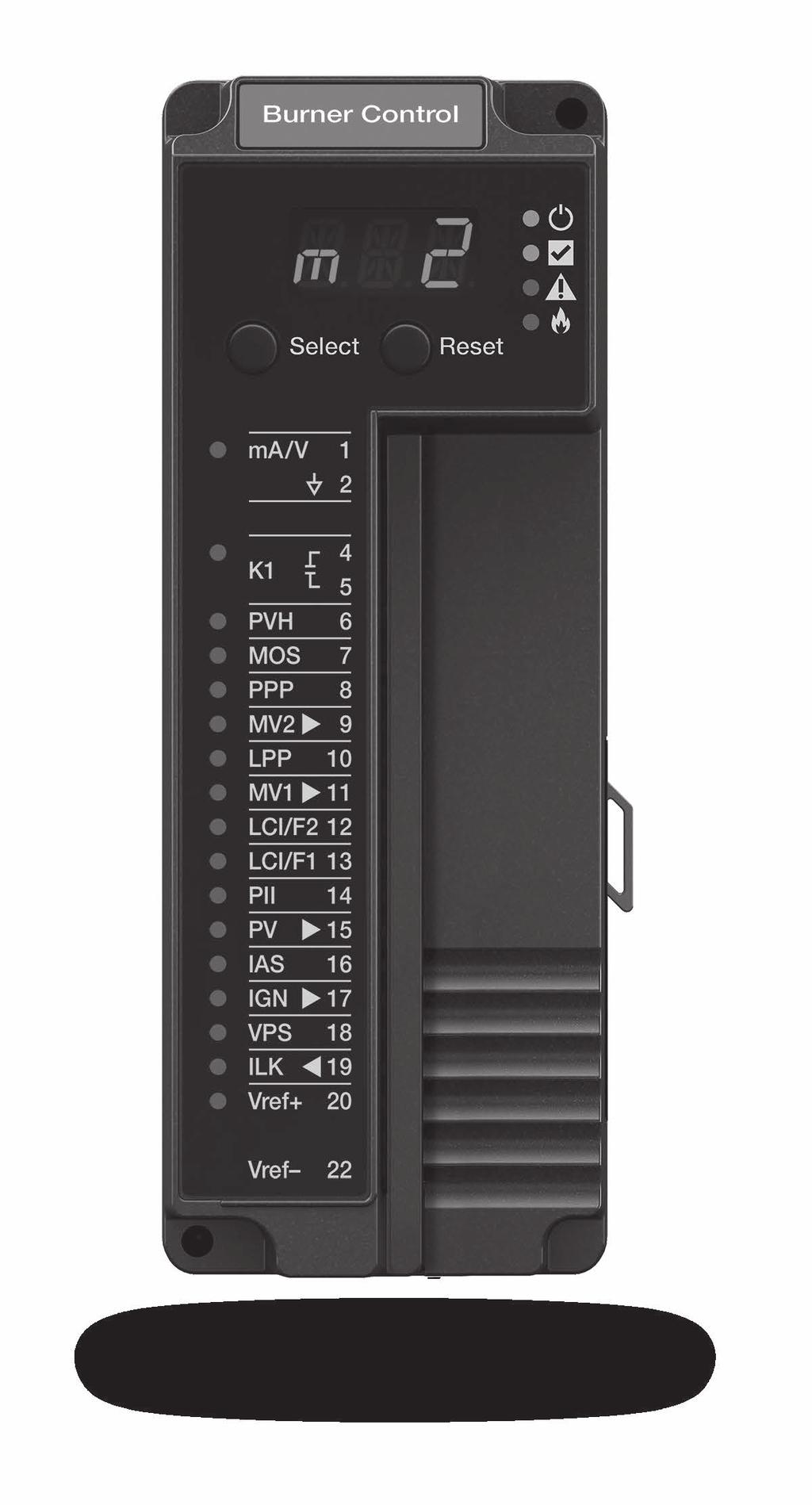
6 LED Array There are four LEDs on the front of the burner control module that provide quick identification of system status and problems. This status is broadcast to other modules on the platform bus in case they are affected by the inoperable module(s). See Table 1 for descriptions. LED Color Description Power No light System does not have power Green System has power CPU Fault Flame Red Green Red No light Yellow No light Table 1. LED Descriptions. LED Displays No valid configuration Running Fault No fault Flame is detected No flame is detected The SLATE system modules have three-character LED displays used for indicating the module number of the SLATE system. They also have three-position LED colors to indicate terminal states as shown in Table 2. Color Green Red No light Description Terminal is ON or is Normal Fault Terminal is OFF or Not in use Table 2. Terminal LED Meanings
7 Select and Reset Buttons The SLATE Burner Control have Select and Reset buttons located on the front of the module and beneath the segment display. The Reset button is used to clear a lockout and reset the module. The Select button is used to scroll through the segment display information. There are also 22 LEDs for each of the burner control module terminals. Installation WARNING Fire or Explosion Hazard Can cause severe injury, death, or property damage. Verification of safety requirements must be performed each time a control is installed on a burner to prevent possible hazardous burner operation. When Installing This Product 1. Read these instructions carefully. Failure to follow them could damage the product or cause a hazardous condition. 2. Check the ratings given in the instructions and on the product to make sure the product is suitable for your application. 3. After installation is complete, check out the product operation as provided in these instructions. 4. The SLATE module must be mounted in an electrical enclosure with adequate clearance for servicing, installation and removal of modules. WARNING Electrical Shock Hazard. Can cause severe injury, death or equipment damage. SLATE BURNER CONTROL MODULE 7 R8001B2001
8 1. Disconnect the power supply before beginning installation to prevent electrical shock and equipment damage. More than one power supply disconnect can be involved. M35383 Fig. 2. Installing the Burner Control Module on the Sub-Base Module. 2. Wiring must comply with all applicable codes, ordinances and regulations. 3. Wiring must comply with NEC Class 1 (Line Voltage) wiring. 4. The R8001B2001 should not interfere with the proper safety operation of the controls, limits and interlocks it is monitoring. After installation, check each control, limit and interlock to ensure that it is operating properly. DO NOT PLACE JUMPER WIRES ACROSS THE INSTALLATION CONTROLS, LIMITS AND INTERLOCKS
9 IMPORTANT 1. This equipment generates, uses and can radiate radio frequency energy and, if not installed and used in accordance with these instructions, may cause interference for radio communications. It has been tested and found to comply with the limits of a Class A computing device of part 15 of FCC rules, which are designed to provide reasonable protection against such interference when operated in a commercial environment. Operation of this equipment in a residential area may cause interference; in which case, the user, at their own expense, may be required to take whatever measures are required to correct this interference. 2. This digital apparatus does not exceed the Class A limits for radio noise, set out in the Radio Interfeence Regulations of the Canadian Department of Communications. 3. Cable shield must be terminated to ground at both ends. If shielded cable is NOT used, use three-wire twisted cable. Wiring WARNING Fire or Explosion Hazard Can cause severe injury, death, or property damage. Disconnect the power supply from the main disconnect before beginning installation to prevent electrical shock and equipment damage. More than one disconnect can be required. Terminal Description Rating 1 Unused (reserved for --- future use) 2 Unused (reserved for --- future use) 3 Unused K1 Relay Dry Contacts (Burner / Fan Motor) 9.8 FLA, VAC, 4A (0.5 PF), 20A 240VAC SLATE BURNER CONTROL MODULE 9 R8001B2001
10 Terminal Description Rating 5 K1 Relay Dry (see above) Contacts 6 Pilot Valve Hold (PVH) 7 Manual Open Switch (MOS) 8 Purge Position Proven (PPP) 9 Main Valve 2 (MV2) 120VAC (see Table 2), 4A (0.5 PF), 20A 240VAC, 2A cont, 10A 24VDC 10 Lightoff Position Proven (LPP) 11 Main Valve 1 (MV1) 120VAC (see Table 2), 4A (0.5 PF), 20A 240VAC, 2A cont, 10A 24VDC 12 Limit and Control Input (LCI) / Fuel (F) 2 13 Limit and Control Input (LCI) / Fuel (F) 1 14 Pre-Ignition Interlocks (PII) 15 Pilot Valve (PV) 120VAC (see Table 2), 4A (0.5 PF), 20A 240VAC, 1A cont, 5A 24VDC 16 Interrupted Air Switch (IAS) 17 Ignition (IGN) 120VAC (see Table 2), 4A ( VAC, 1A cont, 5A 24VDC 18 Valve Proving Switch (VPS)
11 Terminal Description Rating 19 Lockout Interlocks (ILK) 20 Vref+ 24VDC (0.1mA), 24VAC (0.1mA), VAC (0.2mA) 21 Unused Vref- (see Vref+ above) Note: only one voltage can be used per module (same at all terminals). Table 3. Terminal Ratings. Combination Pilot Valve Ignition MV1 & MV2 1 C no load E 2 B no load E 3 E A E 4 D A E 5 D A D Load Table Key A 4.5 A Ignition B C D E 4.5 A plus 50 VA Pilot Duty 180 VA Ign plus motor valves with: 660 VA inrush, 360 VA open, 250 VA hold 2 A Pilot Duty 65 VA Pilot Duty plus motor valves with: 3850 VA inrush, 700 VA open, 250 VA hold Table 4. Combinations for PV, IGN, MV1 & MV2 Terminals. SLATE BURNER CONTROL MODULE 11 R8001B2001
12 Application Recommended Wire Size Recommended Part Numbers Line voltage terminals 14, 16 or 18 AWG copper conductor, 600 volt insulation, moisture-resistant wire. TTW60C, THW75C, THHN90C Communication Lines Other terminals 22 AWG two-wire twisted pair with ground, or fivewire. 18 AWG wire insulated for voltages and temperatures for given application. Table 5. Recommended Wire Sizes and Part Numbers. Belden 8723 shielded cable or equivalent. TTW60C, THW75C, THHN90C Recommended Grounding Practices Use an Earth ground or a signal ground as described below. Earth ground (Base, Rectification Flame Amp Module, other modules optional) 1. Use to provide a connection between the base and the control panel of the equipment. Earth ground must be capable of conducting enough current to blow the breaker in the event of an internal short circuit. 2. Use wide straps or brackets to provide minimum length, maximum surface area ground conductors. If a leadwire is required, use 14 AWG copper wire. 3. Make sure that mechanically tightened joints along the ground path are free of nonconductive coatings and protected against corrosion on mating surfaces. Signal ground Note the 18V system ground is not electrically connected to earth ground. Follow local codes and appliance recommendations to determine if this should be connected to earth ground
13 Recommended wire routing of leadwires Do not run high voltage ignition transformer wires in the same conduit with the flame detector or data lines. Do not route flame detector or data lines in conduit with line voltage circuits. Enclose flame detector leadwires without armor cable in metal cable or conduit. Follow directions in flame detector instructions. Be sure loads do not exceed the terminal ratings. Refer to the labels or terminal ratings in Table 3. The SLATE system must be mounted in an electrical enclosure. When mounting in an electrical enclosure, provide adequate clearance for servicing, installation and removal of SLATE modules. Maximum wire length: The maximum leadwire length is 300 feet to terminal inputs (Control, Running/Lockout Interlock) For remote reset leadwires, maximum length to remote pushbutton is 1000 feet. For Remote Bus data lines, maximum cable length depends on the number of modules connected, the noise conditions and the cable used. The maximum of all interconnecting wires is 4000 feet. SLATE BURNER CONTROL MODULE 13 R8001B2001
14 BURNER CONTROL MODULE 6 RELAYS 15 OPTO-INPUTS UNUSED 4 5 BLR, HSI OR WIRE SHEET 6 PVH 7 M05 8 PPP 9 MV2 10 LPP 11 MV1 12 LCI FUEL2 13 LCI FUEL1 14 PII 15 PV 16 IAS 17 IGN SAFETY RELAY 18 VPS 19 ILK 20 REMOTE BUS IS ON SUBBASE BIAS VREF M35387 Fig. 3. Wiring diagram for Burner Control Module
15 SLATE BURNER CONTROL MODULE 15 R8001B2001
16 For more information on the R8001B2001 and the entire SLATE system please refer to the SLATE User Guide located on our website at Automation and Control Solutions Honeywell International Inc. U.S. Registered Trademark Douglas Drive North 2015 Honeywell International Inc. Golden Valley, MN M.S customer.honeywell.com Printed in U.S.A.
SLATE. Sub-Base Module INSTALLATION INSTRUCTIONS R8001S9001
 SLATE Sub-Base Module R8001S9001 INSTALLATION INSTRUCTIONS Scan for more information Application SLATE brings configurable safety and programmable logic together into one single platform. The platform
SLATE. Base Module INSTALLATION INSTRUCTIONS R8001A1001
 SLATE Base Module R8001A1001 INSTALLATION INSTRUCTIONS Scan for more information Application SLATE brings configurable safety and programmable logic together into one single platform. The platform can
SLATE. Rectification Ampli-Check Flame Amplifier INSTALLATION INSTRUCTIONS R8001V1031
 SLATE Rectification Ampli-Check Flame Amplifier R8001V1031 INSTALLATION INSTRUCTIONS Scan for more information Application SLATE brings configurable safety and programmable logic together into one single
SLATE. UV Ampli-Check Flame Amplifier INSTALLATION INSTRUCTIONS R8001S1071
 SLATE UV Ampli-Check Flame Amplifier R8001S1071 INSTALLATION INSTRUCTIONS Scan for more information Application SLATE brings configurable safety and programmable logic together into one single platform.
7800 SERIES RM7888A Relay Module
 7800 SERIES RM7888A Relay Module SPECIFICATION DATA FEATURES APPLICATION The Honeywell RM7888A Relay Module is a microprocessor-based integrated burner control for industrial process semi-automatically
RM7895A,B,C,D/EC7895A,C; RM7896A,B,C,D 7800 SERIES Relay Modules
 RM79A,B,C,D/EC79A,C; RM796A,B,C,D 700 SERIES Relay Modules INSTALLATION INSTRUCTIONS APPLICATION The RM79A,B,C,D/EC79A,C; RM796A,B,C,D are microprocessor-based integrated burner controls for automatically
7800 SERIES RM7888A Relay Module
 7800 SERIES RM7888A Relay Module FEATURES SPECIFICATION DATA APPLICATION The Honeywell RM7888A Relay Module is a microprocessor-based integrated burner control for industrial process semi-automatically
7800 SERIES 22-Terminal Universal Subbase
 7800 SERIES 22-Terminal Universal Subbase FEATURES PRODUCT DATA Q7800B003/2003/U Metal Wall-mount subbase Q7800A005/2005/U Plastic Wall-mount subbase Quick-mount wiring subbase for all 7800 SERIES Relay
RM7838A 7800 SERIES Relay Modules
 RM788A 7800 SERIES Relay Modules APPLICATION The Honeywell RM788A is a microprocessor-based integrated burner control for semi-automatically fired gas, oil, or combination fuel single burner applications.
7800 SERIES EC7823/RM7823 Relay Module
 7800 SERIES EC7823/RM7823 Relay Module FEATURES SPECIFICATION DATA APPLICATION The Honeywell EC7823/RM7823 is a microprocessor based Flame Detector Relay that can be fitted with any 7800 SERIES amplifier
7800 SERIES EC7885A/RM7885A Relay Module
 7800 SERIES EC7885A/RM7885A Relay Module SPECIFICATION DATA 1. Torch-ignited main burner using the S445A Start-Stop Station, or any conventional knee or foot operated start-stop station. 2. Torch-ignited
7800 SERIES S7830 Expanded Annunciator
 7800 SERIES S7830 Expanded Annunciator PRODUCT DATA FEATURES APPLICATION The S7830 Expanded Annunciator is an enhancement module for use with 7800 SERIES Relay Modules. The S7830 is a microprocessor-based
INSTALLATION INSTRUCTIONS
 SLATE 10 Color Touch Screen Display R8001K1010 INSTALLATION INSTRUCTIONS Scan for more information Application SLATE brings configurable safety and programmable logic together into one single platform.
YP7999A1000 ControLinks Fuel Air Ratio Control Panel
 YP7999A1000 ControLinks Fuel Air Ratio Control Panel FEATURES INSTALLATION INSTRUCTIONS Pre-wired and ready to install Includes the R7999A control, wiring subbase and S7999D1048 touchscreen display Commission,
7800 SERIES RM7840E,G,L,M; EC7840L Relay Module
 7800 SERIES RM7840E,G,L,M; EC7840L Relay Module SPECIFICATION DATA Valve Proving features including: VPS test time When (Never, Before, After, Split or Both) FEATURES APPLICATION The Honeywell RM7840 is
RM7897A,C 7800 SERIES Relay Modules
 RM7897A,C 7800 SERIES Relay Modules INSTALLATION INSTRUCTIONS APPLICATION The RM7897A,C are microprocessor-based integrated burner controls for automatically fired gas, oil, or combination fuel single
7800 SERIES EC7890A,B; RM7890A,B,C Relay Module
 7800 SERIES EC7890A,B; RM7890A,B,C Relay Module SPECIFICATION DATA EC7890 APPLICATION RM7890 The Honeywell EC7890A,B/RM7890 is a microprocessor based integrated burner control for automatically fired gas,
RM7895A,B,C,D/EC7895A,C; RM7896A,C,D 7800 SERIES
 RM7895A,B,C,D/EC7895A,C; RM7896A,C,D 7800 SERIES Relay Modules INSTALLATION INSTRUCTIONS APPLICATION The RM7895A,B,C,D/EC7895A,C; RM7896A,B,C,D are microprocessor-based integrated burner controls for automatically
R7120M 7800 SERIES Relay Modules
 R7120M 7800 SERIES Relay Modules INSTALLATION INSTRUCTIONS APPLICATION The R7120M are microprocessor-based integrated burner controls for automatically fired gas, oil, or combination fuel single burner
7800 SERIES EC7895A,C; RM7895A,B,C,D and RM7896A,B,C,D Relay Modules
 7800 SERIES EC7895A,C; RM7895A,B,C,D and RM7896A,B,C,D Relay Modules SPECIFICATION DATA FEATURES APPLICATION The Honeywell EC7895/RM7895/RM7896 is a microprocessor based integrated burner control for automatically
Q7800H Integrated Burner Control Subpanel
 Q7800H Integrated Burner Control Subpanel INSTALLATION INSTRUCTIONS FEATURES Unique subpanel design eliminates extensive wiring in the OEM control panel. One subpanel design covers multiple applications.
RM7890A1056, RM7890B SERIES
 RM7890A1056, RM7890B1048 7800 SERIES Relay Modules INSTALLATION INSTRUCTIONS APPLICATION The Honeywell RM7890A1056 and RM7890B1048 Relay Modules are microprocessor based integrated burner controls for
R7824, R7847, R7848, R7849, R7851, R7852, R7861, R7886 Amplifiers for 7800 SERIES and R7140 Relay Modules
 R7824, R7847, R7848, R7849, R7851, R7852, R7861, R7886 Amplifiers for 7800 SERIES and R7140 Relay Modules PRODUCT DATA indicate the presence of flame when used with 7800 SERIES and R7140 Relay Modules.
7800 SERIES: EC7895A,C; RM7895A,B,C,D; RM7896A,B,C,D RM7897A,C and RM7898A Relay Modules
 7800 SERIES: EC7895A,C; RM7895A,B,C,D; RM7896A,B,C,D RM7897A,C and RM7898A Relay Modules SPECIFICATION DATA The RM7897A1002 offers selectable pilot operation, intermittent on terminal 8 or interrupted
RM7890D; RM7895E,F 7800 SERIES Relay Modules
 RM7890D; RM7895E,F 7800 SERIES Relay Modules PRODUCT DATA The RM7890D; RM7895E,F provides automatic burner sequencing, flame supervision, system status indication, system or self-diagnostics and troubleshooting.
7800 SERIES RM7840E,G,L,M Relay Module
 7800 SERIES RM7840E,G,L,M Relay Module APPLICATION SPECIFICATION DATA The Honeywell RM7840 is a microprocessor based integrated burner control for automatically fired gas, oil or combination fuel single
R7824, R7847, R7848, R7849, R7851, R7852, R7861, R7886 Amplifiers for 7800 SERIES and R7140 Relay Modules
 R7824, R7847, R7848, R7849, R7851, R7852, R7861, R7886 Amplifiers for 7800 SERIES and R7140 Relay Modules PRODUCT DATA indicate the presence of flame when used with 7800 SERIES and R7140 Relay Modules.
RM7890; RM Vac 7800 SERIES Relay Modules
 RM7890; RM7895 00 Vac 7800 SERIES Relay Modules PRODUCT DATA The RM7890; RM7895 provides on/off automatic burner sequencing, flame supervision, system status indication, system or self-diagnostics and
7800 Series RM7888A Relay Module
 7800 Series RM7888A Relay Module FEATURES PRODUCT DATA APPLICATION The Honeywell RM7888A Relay Module is a microprocessor based, integrated burner control for industrial process semiautomatically fired
7800 SERIES S7800A2142 Keyboard Display Module
 7800 SERIES S7800A2142 Keyboard Display Module PRODUCT DATA The S7800A2142 KDM offers the following technical advancements to the 7800 SERIES devices: APPLICATION The S7800A2142 Keyboard Display Module
Cleaver-Brooks CB780/CB784 Operation and Maintenance Manual
 $25.00 Cleaver-Brooks CB780/CB784 Operation and Maintenance Manual 750-166 DIVISION OF AQUA-CHEM, INC. TO: Owners, Operators and/or Maintenance Personnel This manual presents information that will help
APPLICATION SPECIFICATIONS INSTALLATION INSTRUCTIONS. The following assumptions apply when using the RM7840G,L, RM7800L, EC7840L:
 INSTALLATION INSTRUCTIONS APPLICATION The Honeywell RM7800L/40G,L and EC7840L Relay Modules are microprocessor-based integrated burner controls for automatically fired gas, oil, or combination fuel single
7800 SERIES EC7810A, EC7820A Relay Module
 7800 SERIES EC780A, EC780A Relay Module PRODUCT DATA GENERAL The Honeywell EC780A or EC780A Relay Module is a microprocessor based integrated burner control for automatically fired gas, oil, or combination
Commercial/Industrial Combustion Control Level Three Announcement
 Commercial/Industrial Combustion Control Level Three Announcement SUBJECT: C6097 requiring venting Model Numbers Affected: C6097A and B Ref. Number L3-08-006 Issue Date 12/9/08 Author P.Yuen/L.Ziller Date
ELECTRONIC FLAME SUPERVISION MULTI-BURNER
 MULTI-BURNER MODEL: SENS-A-FLAME II Revision: 0 7112 DESCRIPTION Model 7112 Sens-A-Flame II is a second generation solid-state programmable combustion safeguard for supervising multiple burner ovens, furnaces,
R7824, R7847, R7848, R7849, R7851, R7852, R7861, R7886 Amplifiers for 7800 SERIES and R7140 Relay Modules
 R784, R7847, R7848, R7849, R7851, R785, R7861, R7886 Amplifiers for 7800 SERIES and R7140 Relay Modules PRODUCT DATA and R7140 Relay Modules. This is not European Community (CE) approved for EC7810, EC780,
R7910A SOLA (Hydronic Control) and R7911 SOLA (Steam Control) Systems
 and R7911 SOLA (Steam Control) Systems") R7910A SOLA (Hydronic Control) and R7911 SOLA (Steam Control) Systems APPLICATION The R7910 SOLA hydronic boiler and the R7911 SOLA steam control systems provide heat control, flame supervision, circulation
R7910A SOLA (Hydronic Control) and R7911 SOLA (Steam Control) Systems APPLICATION The R7910 SOLA hydronic boiler and the R7911 SOLA steam control systems provide heat control, flame supervision, circulation
YP7899C SERIES Burner Management Panel
 YP7C1000 700 SERIES Burner Management Panel INSTALLATION INSTRUCTIONS 65-00, ST700A,C 700 SERIES Plug-In Purge Timer 65-0, S710M Modbus Module 60-06, C707, C7035, C70, C77 Minipeeper UV Flame Detector
7800 SERIES S7800A1167 Keyboard Display Module
 7800 SERIES S7800A1167 Keyboard Display Module PRODUCT DATA The S7800A1167 KDM offers the following technical advancements to the 7800 SERIES devices: Compatible with installed Honeywell 7800 SERIES systems.
Honeywell SLATE ICM Platform
 Honeywell SLATE ICM Platform SUBMITTAL SPECIFICATION Note to specifiers: To specify Honeywell SLATE Integrated Combustion Management System with specified packaged boiler manufactures, Copy and Paste both
7800 SERIES RM7824A Relay Module
 7800 SERIES RM7824A Relay Module FEATURES PRODUCT DATA APPLICATION The Honeywell RM7824A Relay Module is a 24 Vdc microprocessor-based integrated burner control for automatically fired gas, oil or combination
T7079A,B Solid State Remote Temperature Controllers
 T7079A,B Solid State Remote Temperature Controllers FEATURES PRODUCT DATA Switch selection of heat or cool mode. Temperature sensing up to 400 feet. Does not require field calibration. 0K NTC temperature
R7910A SOLA (Hydronic Control) and R7911 SOLA (Steam Control) Systems
 and R7911 SOLA (Steam Control) Systems") R7910A SOLA (Hydronic Control) and R7911 SOLA (Steam Control) Systems INSTALLATION INSTRUCTIONS APPLICATION The R7910 SOLA hydronic boiler and the R7911 SOLA steam control systems provide heat control,
R7910A SOLA (Hydronic Control) and R7911 SOLA (Steam Control) Systems INSTALLATION INSTRUCTIONS APPLICATION The R7910 SOLA hydronic boiler and the R7911 SOLA steam control systems provide heat control,
IS Series Pressure Sensing Switches
 IS Series Pressure Sensing Switches FEATURES INSTALLATION INSTRUCTIONS IS3 PRESSURE SWITCH APPLICATION IS2 PRESSURE SWITCH The IS Series of pressure sensing switches offers the same proven compression
CR Series Command Relays
 CR Series Command Relays FEATURES INSTALLATION INSTRUCTIONS Patented 35mm Din-rail mounting flange (US Patent 7,416,421) SPDT Form 1C Relay contacts Pilot duty rated LED status indication Stackable for
MBCE-110/230FR Flame Sensor Module
 MBCE-1001 APRIL 13, 2012 MBCE-110/230FR Flame Sensor Module DESCRIPTION The MBCE-110/230FR modules provide visual indication and electrical outputs that signal the user regarding flame presence in a combustion
Instructions For A and Flame Simulators
 Instructions For 123514A and 203659 Flame Simulators Application Flame simulators are devices that simulate a flame by reproducing ultraviolet resistance or rectification characteristics of an actual flame.
LFL Series Burner Flame Safeguard Control
 LFL Series Burner Flame Safeguard Control Technical Instructions Document No. 74US LFL Rev. 2 November, 2004 The LFL is a compact electro-mechanical primary flame safeguard control designed to provide
RA890G Protectorelay Primary Control
 Protectorelay Primary Control The RA890G Protectorelay control provides solid state electronic safeguard protection for industrial and commercial gas, oil, or combination gas-oil burners. Designed for
FIREYE M4RT1 FLAME SAFEGUARD CONTROLS DESCRIPTION
 M-4000 JANUARY 29, 200 FIREYE M4RT1 FLAME SAFEGUARD CONTROLS WARNING: Selection of this control for a particular application should be made by a competent professional, licensed by a state or other government
Sola Hydronic Control. An Eco-Friendly Solution.
 Sola Hydronic Control An Eco-Friendly Solution. Honeywell s Sola Boiler Control saves you money and reduces your carbon footprint! Efficient Boiler Control Honeywell s Sola Boiler Control offers energy
R7910A SOLA HC (Hydronic Control) R7911 SOLA SC (Steam Control)
 R7911 SOLA SC (Steam Control)") R7910A SOLA HC (Hydronic Control) R7911 SOLA SC (Steam Control) APPLICATION PRODUCT DATA The R7910A SOLA HC is a hydronic boiler control system and the R7911 SOLA SC is a Steam Control system that provide
R7910A SOLA HC (Hydronic Control) R7911 SOLA SC (Steam Control) APPLICATION PRODUCT DATA The R7910A SOLA HC is a hydronic boiler control system and the R7911 SOLA SC is a Steam Control system that provide
C554A Cadmium Sulfide Flame Detector
 C554A Cadmium Sulfide Flame Detector FEATURES PRODUCT DATA Cadmium sulfide sensing element provides faster response than bimetal sensors. On flame failure, the cad cell causes the oil primary control to
R7824, R7847, R7848, R7849, R7851,R7861, R7886 Amplifiers for 7800 SERIES Relay Modules
 R784, R7847, R7848, R7849, R7851,R7861, R7886 Amplifiers for 7800 SERIES Relay Modules PRODUCT DATA The R7851C Dynamic Self- Optical lame Amplifier is a solid state plug-in amplifier that responds to ultraviolet
Solid Core and Split Core 0-5, 0-10 Vdc Output Current Sensors CTS-05,10; CTP-05,-10
 Solid Core and Split Core 0-5, 0-10 Vdc Output Current Sensors CTS-05,10; CTP-05,-10 DESCRIPTION FEATURES PRODUCT DATA Solid and Split Core Vdc Output Current Transmitters. Fast Response Time. Integral
MBCE-110/230FR Flame Sensor Module
 MBCE-1001 FEBRAURY 6, 2017 MBCE-110/230FR Flame Sensor Module exida FMEDA SIL2 SEE NOTE 1 ON PAGE 4 DESCRIPTION The MBCE-110/230FR modules provide visual indication and electrical outputs that signal the
MBCE-110/230UV Flame Sensor Module
 MBCE-1002 FEBRUARY 3, 2017 MBCE-110/230UV Flame Sensor Module DESCRIPTION The MBCE-110/230UV modules provide visual indication and electrical outputs that signal the user regarding flame presence in a
Refer to Bulletin E-1101 for detailed information on the FLAME-MONITOR System.
 The Fireye EP260, EP270 (early spark termination), or EP265 (pilot stabilization) programmer modules are used with the FLAME-MONITOR Burner Management Control System (P/N E110). Several operational characteristics
C6097A,B Pressure Switches
 C6097A,B Pressure Switches FEATURES PRODUCT DATA APPLICATION The C6097 Pressure Switches are safety devices used in positive-pressure or differential-pressure systems to sense gas or air pressure changes.
Power Supply Display Module PSDM. Installation and Operation Manual
 Power Supply Display Module PSDM Installation and Operation Manual Read this manual before using this product. Failure to follow the instructions and safety precautions in this manual can result in serious
C7007A, C7008A, C7009A Flame Rod Holder & Flame Rod Assemblies
 Flame Rod Holder & Flame Rod Assemblies The small size of these devices enable their application to flame detection in installations where space is limited. The holder and flame rod assemblies facilitate
MBUV-100D, MBUVS-100D MBIR-100D, MBFR-100D DIN RAIL MOUNT FLAMEWORX MODULES
 MBD-00 FEBRUARY 00 MBUV-00D, MBUVS-00D MBIR-00D, MBFR-00D DIN RAIL MOUNT FLAMEWORX MODULES APPROVED Year 000 Compliant in accordance with BSI document DISC PD000-I:998 DESCRIPTION Fireye offers a complete
BC-R10 Series. Burner Controllers
 No. CP-SS-1885E BC-R10 Series Burner Controllers Summary BC-R10 Series burner controllers are combustion safety controllers specifically designed for batch operation (systems which start and stop at least
Eclipse Self-Check UV Scanner
 856 Instruction Manual 10/18/2010 Eclipse Self-Check UV Model 5602-91 Version 1 Introduction The self-check UV is used for continuous gas or oil flames. A mechanical shutter in the scanner closes briefly
R7140G,L,M Burner Control Modules
 R0G,L,M Burner Control Modules FEATURES INSTALLATION INSTRUCTIONS APPLICATION The Honeywell R0G,L,M Burner Control Modules are microprocessor-based integrated burner controls for automatically fired gas,
Model 17A00 Expansion Enclosure
 HOME AUTOMATION, INC. Model 17A00 Expansion Enclosure Installation Manual Document Number 17I00-1 Rev A March, 2002 Home Automation, Inc. Model 17A00 Expansion Enclosure Installation Manual Document Number
L8005A,B; LS8005A,C,D Electronic Pool and Spa Controllers
 Electronic Pool and Spa Controllers The L8005A,B and LS8005A,C,D Electronic Pool and Spa Controllers are used in pool, spa, and hot tub applications to control water temperature. Remote Potentiometer L8005A,B
PARAGON Commercial Refrigeration Controls
 PARAGON Commercial Refrigeration Controls ERC 2 Electronic Refrigeration Control The ERC 2 Electronic Refrigeration Control is a microprocessor-based electronic controller designed to control both the
Pipe Freeze Protection Control SCFP-CO-F130 Installation and Operation Manual
 MANUAL Pipe Freeze Protection Control SCFP-CO-F130 Installation and Operation Manual Model FPT 130 Single Point Freeze Protection Heat Trace Control Table of Contents SCFP-CO-F130 Overview... 3 Installation...
C7005A,B Gas Pilot and Flame Rod Assemblies
 C7005A,B Gas Pilot and Flame Rod Assemblies FEATURES PRODUCT DATA Used with Honeywell controls using the flame rectification principle. C7005A is for continuous pilot applications. It includes an insulated
C7232A,B Sensor and Controller CARBON DIOXIDE SENSOR
 C7232A,B Sensor and Controller CARBON DIOXIDE SENSOR PRODUCT DATA C7232A C7232B FEATURES Used for CO 2 based ventilation control. Models available with LCD that provides sensor readings and status information.
50A Integrated Furnace Control
 Goodman White-Rodgers 0130F00005 PCBBF110 PCBBF123 50A55-743 0130F00005S PCBBF110S PCBBF123S 50A55-289 B1809926 PCBBF112 50T55-289 B1809926S PCBBF112S 50A55-743 Integrated Furnace Control INSTALLATION
SAFETY CONTROL REQUIREMENTS FOR OVENS AND FURNACES
 SAFETY CONTROL REQUIREMENTS FOR OVENS AND FURNACES SAFETY CONTROL REQUIREMENTS The NATIONAL FIRE PROTECTION ASSOCIATION is organized to promote the science and improve the methods of fire protection and
EUROBOX SERIES TYPES CM... SM... MM...
 EUROBOX SERIES TYPES CM... SM... MM... AUTOMATIC GAS BURNER CONTROL SYSTEMS FOR GAS BURNERS AND GAS BURNING APPLIANCES WITH OR WITHOUT FAN Application This range of electronic gas burner control systems
T7984 A,B,C Electronic Modulating Control Thermostats
 T7984 A,B,C Electronic Modulating Control Thermostats FEATURES PRODUCT DATA APPLICATION These microprocessor-based thermostats provide proportional - integral (PI) individual room temperature control in
Submittal. Date: September 04, Customer P.O. Number: Customer Project Number:
 Submittal Prepared For: All Bidders Sold To: Date: September 04, 2012 Customer P.O. Number: Customer Project Number: Job Number: Job Name: DCS 12473 80 Ton Chiller Dept of Wildlife 1801 N Lincoln OKLAHOMA
Solid Core and Split Core 4-20 ma Output Current Sensors CTS-20; CTP-20
 Solid Core and Split Core 4-20 ma Output Current Sensors CTS-20; CTP-20 PRODUCT DATA FEATURES Solid or split core loop-powered current transmitters Fast response time Integral DIN rail mounting flange
SERIES VAC Microprocessor-Based Hot Surface Ignition Control FEATURES APPLICATIONS SPECIFICATIONS DESCRIPTION AGENCY CERTIFICATIONS
 SERIES 35-65 24 VAC Microprocessor-Based Hot Surface Ignition Control F-35-65 August 2015 FEATURES Safe start with DETECT-A-FLAME flame sensing technology Custom pre-purge and inter-purge timings* 120/240
CAUTION WARNING. 50T Integrated Furnace Control INSTALLATION INSTRUCTIONS DESCRIPTION PRECAUTIONS
 50T35-743 Integrated Furnace Control INSTALLATION INSTRUCTIONS FAILURE TO READ AND FOLLOW ALL INSTRUCTIONS CAREFULLY BEFORE INSTALLING OR OPERATING THIS CONTROL COULD CAUSE PERSONAL INJURY AND/OR PROPERTY
C7915A Infrared Flame Detector
 C795A Infrared Flame Detector PRODUCT DATA When installed properly, can supervise the pilot flame and/ or the main burner flame. Mounts easily on a standard 3/ inch sight pipe. The infrared sensor plugs
FIREYE NXF4000 ADVANCED BURNER MANAGEMENT SYSTEM with INTERNAL FLAME SAFEGUARD
 BURNER MANANGEMENT SYSTEM NXF4000-SPEC AUGUST 5 2017 PRODUCT GUIDE SPECIFICATION FIREYE NXF4000 ADVANCED BURNER MANAGEMENT SYSTEM with INTERNAL FLAME SAFEGUARD GENERAL OVERVIEW 1.1.1. Each burner shall
RA889A Switching Relay
 Switching Relay INSTALLATION INSTRUTIONS APPLIATION The Switching Relay provides intermediate switching of line- and low-voltage devices from a line- or low-voltage controller and is typically applied
LC3000 Level Controller Installation and Maintenance Instructions
 4025550/12 IM-P402-36 AB Issue 12 LC3000 Level Controller Installation and Maintenance Instructions 1. General safety information LC3000 NORM ALARM TEST 2. General product information 3. Installation 4.
50A Integrated Furnace Control
 50A56-956 Integrated Furnace Control INSTALLATION INSTRUCTIONS FAILURE TO READ AND FOLLOW ALL INSTRUCTIONS CAREFULLY BEFORE INSTALLING OR OPERATING THIS CONTROL COULD CAUSE PERSONAL INJURY AND/OR PROPERTY
configurable safety and programmable logic SLATE Integrated Combustion Equipment Management The revolutionary integration of
 SLATE Integrated Combustion Equipment Management The revolutionary integration of configurable safety and programmable logic in a single, modular platform Complexity. This is today. Individual components
Single Point Freeze Protection Heat Trace Control TRACON MODEL FPT 130 Installation and Operation Manual
 We manage heat MANUAL Single Point Freeze Protection Heat Trace Control TRACON MODEL FPT 130 Installation and Operation Manual 1850 N Sheridan Street South Bend, Indiana 46628 (574) 233-1202 or (800) 234-4239
TTSIM-2 TRACETEK SENSOR INTERFACE MODULE WITH LCD AND RELAY INSTALLATION/OPERATION INSTRUCTIONS
 TTSIM-2 TRACETEK SENSOR INTERFACE MODULE WITH LCD AND RELAY INSTALLATION/OPERATION INSTRUCTIONS GENERAL INFORMATION Please read these instructions and keep them in a safe place. These instructions must
Interrupted Ignition Series Oil Primary Control
 Interrupted Ignition Series Oil Primary Control Application Guide & Installation Instruction for ICM1511*, ICM1512*, ICM151*, ICM1514* For more information on our complete range of American-made products
Honeywell Primary Control Cross Reference
 Honeywell Primary Control Cross Reference Page Pages, Page, Page Page Page Pages 9, 0 Page Pages, Page Pages, Page Page Pages 9,0 R, R0, R, R90B, RA90B, R90C, R, R90B RA90B, R90C, RA90C, RA90XB,XC, RA90D
C7232A,B Sensor and Controller
 C7232A,B Sensor and Controller CARBON DIOXIDE SENSOR FEATURES PRODUCT DATA C7232A C7232B Used for CO 2 based ventilation control. Models available with LCD that provides sensor readings and status information.
Solid Core and Split Core Fixed Current Status Switches CSS-O,C; CSP-O,C -F (FIXED) SERIES
 SERIES") Solid Core and Split Core Fixed Current Status Switches CSS-O,C; CSP-O,C -F (FIXED) SERIES PRODUCT DATA FEATURES Solid and Split Core, Fixed Current go/no go switches. Very low operating trip points. LED
Solid Core and Split Core Fixed Current Status Switches CSS-O,C; CSP-O,C -F (FIXED) SERIES PRODUCT DATA FEATURES Solid and Split Core, Fixed Current go/no go switches. Very low operating trip points. LED
THERMAL BUILDING SOLUTIONS EN-TraceTekTTSIM1A-IM-H /16
 TraceTek TTSIM-1A TraceTek Sensor Interface Module with Relay Installation/OPERATION Instructions Approvals and Certifications TYPE NM General Signaling Equipment 76LJ Only AC versions are UL listed and
S9360, S9361, S9370, S9371 Integrated Boiler Controllers
 S9360, S9361, S9370, S9371 Integrated Boiler Controllers INSTALLATION INSTRUCTIONS SPECIFICATIONS IMPORTANT: The specifications given in this publication do not include normal manufacturing tolerances.
Quickheat 30 weather compensated boiler control
 Quickheat 0 weather compensated boiler control A compact and sophisticated heating controller The compact KM controller is designed for the control of fan assisted boilers with modulating burners. The
Dual Input ph/orp Analyzer
 Instruction Sheet PN 51A-1055pH/rev.I February 2006 Model 1055 SOLU COMP II Dual Input ph/orp Analyzer Model Option 1055-22-32 For additional information, please refer to the Instruction Manuals CD shipped
SERIES VAC Microprocessor-Based Intermittent Pilot Ignition Control FEATURES APPLICATIONS SPECIFICATIONS DESCRIPTION
 R SERIES 35-703 120 VAC Microprocessor-Based Intermittent Pilot Ignition Control F-35-703 July 2016 FEATURES Safe start with DETECT-A-FLAME flame sensing technology Custom pre-purge and inter-purge timings
50M Integrated Single or Two-Stage HSI Integrated Furnace Control Kit INSTALLATION INSTRUCTIONS
 50M56-743 Integrated Single or Two-Stage HSI Integrated Furnace Control Kit INSTALLATION INSTRUCTIONS FAILURE TO READ AND FOLLOW ALL INSTRUCTIONS CAREFULLY BEFORE INSTALLING OR OPERATING THIS CONTROL COULD
Dual Input ph/conductivity Analyzer
 Instruction Sheet PN 51A-1055pHC/rev.I January 2006 Model 1055 SOLU COMP II Dual Input ph/conductivity Analyzer Model Option 1055-22-30 For additional information, please refer to the Instruction Manuals
Operator: Save these instructions for future use!
 WHITE-RODGERS 50A55-474 & 50A55-571 Integrated Furnace Controls INSTALLATION INSTRUCTIONS Operator: Save these instructions for future use! FAILURE TO READ AND FOLLOW ALL INSTRUCTIONS CAREFULLY BEFORE
TTSIM-1A. TraceTek Sensor Interface Module with Relay. Installation/Operation Instructions. Installation Items (not supplied) Tools Required.
 Tools Required.") TTSIM-1A TraceTek Sensor Interface Module with Relay Installation Items (not supplied) General Information Installation/Operation Instructions Please read these instructions and keep them in a safe place.
TTSIM-1A TraceTek Sensor Interface Module with Relay Installation Items (not supplied) General Information Installation/Operation Instructions Please read these instructions and keep them in a safe place.