GuardShield Safe 2 and Safe 2 PAC Safety Light Curtains User Manual
|
|
|
- Dayna McKinney
- 5 years ago
- Views:
Transcription


1 GuardShield Safe 2 and Safe 2 PAC Safety Light Curtains User Manual
2 Important User Information Because of the variety of uses for the products described in this publication, those responsible for the application and use of this control equipment must satisfy themselves that all necessary steps have been taken to assure that each application and use meets all performance and safety requirements, including any applicable laws, regulations, codes and standards. The illustrations, charts, sample programs and layout examples shown in the guide are intended solely for purposes of example. Since there are many variables and requirements associated with any particular installation, Rockwell Automation does not assume responsibility or liability (to include intellectual property liability) for actual use based upon the examples shown in this publication. Rockwell Automation publication SGI-1.1, Safety Guidelines for the Application, Installation and Maintenance of Solid-State Control (available from your local Rockwell Automation sales office), describes some important differences between solid-state equipment and electromechanical devices that should be taken into consideration when applying products such as those described in this publication. Reproduction of the contents of this copyrighted publication, in whole or part, without written permission of Rockwell Automation, is prohibited. Throughout this manual we use notes to make you aware of safety considerations: WARNING Identifies information about practices or circumstances that can cause an explosion in a hazardous environment, which may lead to personal injury or death, property damage, or economic loss. IMPORTANT ATTENTION Identifies information that is critical for successful application and understanding of the product. Identifies information about practices or circumstances that can lead to personal injury or death, property damage, or economic loss. Attentions help you identify a hazard, avoid a hazard, and recognize the consequences. SHOCK HAZARD Labels may be on or inside the equipment (for example, drive or motor) to alert people that dangerous voltage may be present. BURN HAZARD Labels may be on or inside the equipment (for example, drive or motor) to alert people that surfaces may reach dangerous temperatures. It is recommended that you save this user manual for future use.
3 Conditions required for proper use of the GuardShield Safe 2 Safety Light Curtain Please make sure you read and understand these requirements before you select and install the GuardShield Safe 2 safety light curtain. GuardShield safety light curtains are point of operation and perimeter access safeguarding devices. These safety light curtains are intended to be used to to provide point of operation and perimeter access safeguarding of personnel on a variety of machinery. The GuardShield Safe 2 family of safety light curtains are general purpose presence sensing devices which are designed to protect personnel working on or near machinery. The installation of GuardShield Safe 2 safety light curtains must comply with all applicable federal, state, and local rules, regulations, and codes. It is the responsibility of the employer to properly install, operate and maintain the product as well as the machinery on which the GuardShield Safe 2 presence sensing device is installed. GuardShield Safe 2 safety light curtains must be properly installed by qualified personnel. GuardShield Safe 2 safety light curtains are presence sensing devices and will not protect personnel from heat, chemicals, or flying parts. They are intended to signal a stop of hazardous machine motion when the sensing field is broken. GuardShield Safe 2 safety light curtains can only be used on machinery which can be stopped anywhere in its stroke or cycle. GuardShield Safe 2 safety light curtains should never be used on full revolution clutched machinery. The effectiveness of the GuardShield Safe 2 safety light curtains depends upon the integrity of the machine control circuit. The machinery on which the GuardShield Safe 2 presence sensing device is installed should have control circuitry that is fail safe in design. All stopping mechanisms for the machinery should be inspected regularly to ensure proper operation. The protected machinery must have a consistent reliable and repeatable stopping time. ATTENTION Failure to read and follow these instructions can lead to misapplication or misuse of the GuardShield Safe 2 safety light curtains, resulting in personal injury and damage to equipment. 1 R
4 Table of Contents Introduction Safety Precautions Principles for Safe Use and Symbols Used Specialist Personnel Range of Uses of the Device Proper Use General Protective Notes and Protective Measures Product Description Special Features Principles of Operation Perimeter Systems (PAC) Examples of Range of Use Safety Functions Generally recognized technical regulations and quality assurance system ISO 9000 are carefully applied during the development and production of Allen-Bradley/ Guardmaster products. This technical description must be followed when installing and commissioning the GuardShield Safe 2. Inspection and commissioning must be carried out by a qualified person. Rockwell Automation reserves the right to make changes or revisions to the material contained in this publication and cannot be held liable for incidental or consequential damages resulting from the furnishing, performance or use of this material. Determining the Safety Distance US Safety Distance Formula OSHA Safety Distance Calculation Formula The ANSI Safety Distance Formula European Safety Distance Formula Installation and Mounting Alignment Procedure Correct Installation Incorrect Installation Multiple GuardShield Safe 2s Mounting Brackets Electrical Installation Connections Typical Wiring Diagram Trouble Shooting Guide Checklist Safety Instructions Maintenance Daily Inspection Six-Month Inspection Cleaning Date Code and Label Technical Specifications Catalog Number Configuration Dimensional Drawings Certificate EC Declaration of Conformity This manual covers the operation and installation of the: GuardShield Safe 2 POC and PAC safety light curtains IMPORTANT Save these instructions for use at a future time. 2
5 Introduction The GuardShield Safe 2 family of safety light curtains are general purpose presence sensing devices, designed for use on hazardous machinery providing point of operation (POC), as well as, perimeter access (PAC) detection. It is a self-contained, two box, Type 2 ESPE (Electro Sensitive Protective Equipment) for use on or around machinery. A formal risk assessment is required to determine if a Type 2 safety device provides a sufficient level of safety for the application. IMPORTANT Safety Precautions Principles for Safe Use and Symbols Used The following instructions are preventive warnings to ensure the safe and proper operation of the GuardShield Safe 2 light curtains. These instructions are an essential part of the safety precautions and therefore have to be observed at any time. Throughout this manual we use the labels ATTENTION and IMPORTANT to alert you to the following: ATTENTION Failure to observe may result in dangerous operation ATTENTION: Identifies information about practices of circumstances that can lead to personal injury or death, property damage, or economic loss. ATTENTION helps you Identify a hazard Avoid a hazard Recognize the consequences IMPORTANT: Identifies information that is especially important for successful application and understanding of the product. ATTENTION These installation instructions are designed to address the technical personnel of the machine manufacturer and or the installer of the safety system regarding the proper mounting, configuration, electrical installation, commissioning, operation and maintenance of the GuardShield Safe 2 safety light curtain. These installation instructions do not provide instruction for the operation of machinery to which the GuardShield Safe 2 safety light curtain is, or will be, integrated. Only qualified personnel should install this equipment. Potentially hazardous situation, which, if not prevented, might lead to serious or deadly injury. Failure to observe may result in dangerous operation. ATTENTION The GuardShield Safe 2 must not be used with machines that cannot be stopped electrically in an emergency. The safety distance between the GuardShield Safe 2 and a dangerous machine movement has to be maintained at all times. Additional mechanical protective devices have to be installed in a way that hazardous machine elements cannot be reached without passing through the protective field. The GuardShield Safe 2 has to be installed in a way that operators can only operate within the sensing area. Improper installation can result in serious injury. Never connect the outputs to +24V DC. If the outputs are connected to +24V DC, they are in ON-state and cannot stop hazardous spots at the machine/application. Never expose the GuardShield Safe 2 to flammable or explosive gases. Regular safety inspections are imperative (see maintenance). Do not repair or modify the GuardShield Safe 2. The GuardShield Safe 2 safety light curtain is not field repairable and can only be repaired at the factory. Removal of either of the GuardShield Safe 2 endcaps will void the warranty terms of this product. Specialist Personnel The GuardShield Safe 2 safety light curtain must be installed, commissioned and serviced only by a qualified person. A qualified person is defined as a person who: Has undergone the appropriate technical training and Who has been instructed by the responsible machine operator in the operation of the machine and the currently valid safety guidelines and Who has read and has ongoing access to these installation instructions Range of Uses of the Device The GuardShield Safe 2 safety light curtain is classified as electrosensitive protective equipment (ESPE). The physical resolution of the POC is 30 mm (1.18 in.). The maximum protective field width of GuardShield Safe 2 POC is: 0 18 m (59.1 ft) for the 30 mm (1.18 in.) resolution 5 30 m ( ft) for the Safe 2 PAC The protective field height is between 120 mm (4.7 in.) and 1920 mm (75.6 in.). The maximum protective field width of GuardShield Safe 2 PAC (2 and 3 beam) is 5 30 m ( ft). All standard GuardShield Safe 2 POC and PAC light curtains have Integrated Laser Alignment. The device is a Type 2 ESPE as defined by IEC and CLC/TS and is therefore allowed for use with controls in safety category 3
6 Type 2 applications up to safety category 2 (EN 954)/SIL2/SIL CL2 (EN 61508/EN 62061) and PLd (EN ISO ). This device is suitable for: Point of operation protection (hand protection) Hazardous area protection Access protection Access to the hazardous point must be allowed only through the protective field. The machine/system is not allowed to start as long as personnel are within the hazardous area. Refer to the Examples of Range of Use on page 5 for an illustration of the protection modes. Depending on the application, mechanical protection devices may be required in addition to the safety light curtain. Proper Use The GuardShield Safe 2 safety light curtain must be used only as defined in the Range of Uses of the Device. It must be used only by qualified personnel and only on the machine where it has been installed and initialized by qualified personnel. If the device is used for any other purposes or modified in any way, warranty claims against Allen-Bradley/Guardmaster shall become null and void. General Protective Notes and Protective Measures IMPORTANT Safety Notes Please observe the following items in order to ensure the proper and safe use of the GuardShield Safe 2 safety light curtain. The national/international rules and regulations apply to the installation, use and periodic technical inspections of the safety light curtain, in particular: Machine Directive 2006/42/EC Low Voltage Directive 2006/95/EC Use of Work Directive (2009/104/EC) The work safety regulations/safety rules Other relevant health and safety regulations Manufacturers and users of the machine with which the safety light curtain is used are responsible for obtaining and observing all applicable safety regulations and rules. The notices, in particular the test regulations of these installation instructions (e.g. on use, mounting, installation or integration into the existing machine controller) must be observed. The tests must be carried out by specialist personnel or specially qualified and authorized personnel and must be recorded and documented to ensure that the tests can be reconstructed and retraced at any time. The installation instructions must be made available to the user of the machine where the GuardShield Safe 2 safety light curtain is installed. The machine operator is to be instructed in the use of the device by specialist personnel and must be instructed to read the installation instructions. Product Description This section provides information on the special features and properties of the safety light curtain. It describes the structure and functions of the unit. Please read this section before mounting, installing and commissioning the unit. Special Features Integrated laser alignment Large range with a compact profile 30mm resolution: 0 18 m or 5 30 m Tolerant to dust and pollution Short-circuit protected semiconductor outputs Built-in-diagnostic LEDs Optical synchronization, no electrical cable needed between transmitter and receiver Maintenance-free and cost effective Principles of Operation The GuardShield Safe 2 safety light curtain consists of a non-matched pair of optic units, i.e., transmitter and receiver with the same protected height and resolution. The transmitter and receiver operate on +24V DC. The maximum distance between transmitter and receiver is referred to as the protective field width or range. The protective field height is the distance between the first and last beam in the device. The transmitter emits sequential pulses of infrared light which are received and processed by the GuardShield Safe 2 receiver. The synchronization of the timing of the emission and reception of infrared light pulses is accomplished optically by the first beam adjacent to the GuardShield Safe 2 status LEDs. This beam is referred to as the synchronization beam. Because the GuardShield Safe 2 transmitter and receiver are optically synchronized, no electrical connection is required between the transmitter and receiver. The GuardShield Safe 2 receiver has two safety outputs, Output Signal Switching Devices (OSSDs). When the GuardShield Safe 2 transmitter and receiver are properly powered and aligned, all OSSDs are current sourcing +24V DC with a switching capacity of 300 ma. The two safety OSSDs are cross monitored and short-circuit protected. Interruption of the sensing field causes the receiver to switch the sourced current OFF (0V DC). Restoring the GuardShield Safe 2 sensing field causes all outputs (OSSDs) to switch to the active high state (resume current sourcing +24V DC with a switching capacity of 300 ma). GuardShield Safe 2 operates in the guard only mode with automatic restart. Other modes of operation e.g. PSDI mode (break mode), muting, external relay monitoring (EDM) can be realized using external safety devices. The GuardShield Safe 2 safety light curtain consists of a transmitter and a receiver. 4

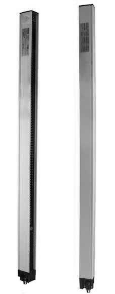
7 Transmitter Receiver 1100 Figure 1: Components of the GuardShield Safe 2 The protective field and the active elements respectively, are clearly recognized as black surfaces with the integrated optical lenses. The width of the protective field is derived from the length of the light path between sender and receiver and must not exceed the maximum rated width of the protective field 0 18 m (59.1 ft) for 30 mm (1.18 in.) resolution, or 5 30 m ( ft) for Safe 2 PAC Perimeter Systems (PAC) Perimeter systems are usually produced by means of several single-beam light barriers. But the flexibility of the GuardShield Safe 2 system allows also the production of vertical entry safeguarding according to the standard EN ISO [2010]. Such systems are composed of active and passive elements in one compact profile. The element length of each is 120 mm (variations are given in the appendix). The protective field and the active elements respectively, are clearly recognized as black surfaces with the integrated optical lenses. The areas not monitored (passive elements) are also clearly indicated as yellow surfaces Reference plane (e.g. ground) Figure 2: Perimeter systems (2- and 3-beams) according to EN ISO (2010) Examples of Range of Use The GuardShield Safe 2 safety light curtain operates as a proper protective device only if the following conditions are met: The control of the machine must be electrical. The controlled machine must be able to be stopped any where in the machines stroke or cycle. The transmitter and receiver must be mounted such that access to the hazard is only through the light curtain s protective field. The restart button must be located outside the hazardous area such that it cannot be operated by a person working inside the hazardous area. The statutory and local rules and regulations must be observed when installing and using the device. 900 IMPORTANT Additional measures may be necessary to ensure that the ESPE does not fail to danger when other forms of light radiation are present in a particular application (i.e., use of cableless control devices on cranes, radiation from weld spatter or effects from strobe lights) Reference plane (e.g. ground) GuardShield Safe 2 Laser Alignment The laser light source in the Integrated Laser Alignment system of the GuardShield Safe 2 light curtains is a Class 2, eye safe laser diode with a wavelength of 630 nm. This Class 2, eye safe laser is switched from a low output power state to a high output power state (and back again) by means of control circuitry which detects reflected laser light from a temporary blockage of the emitted laser light. This is most commonly accomplished by a person s finger placed over the laser overlay window. There is also an automatic shutdown feature that switches the laser diode from the high power state to the low power state if there is no finger or other interruption detected for a period of five minutes. During the high output mode of operation, the laser is pulsed at a rate of approximately 2 Hz in order to facilitate finger detection in high ambient light conditions. 5
8 Class 2 Laser To prevent exposure to laser radiation, do not expose your eyes to the laser. Turn ILAS off if not in use. This distance, referred to as the safety distance, must be properly calculated prior to determining the safety light curtain protective height and mounting the light curtains on the machine. Failure to properly calculate this safety distance may result in operator injury. Safety Functions All GuardShield Safe 2 safety light curtains operated as on/off devices, meaning the OSSD outputs switch off/on according to an obstruction or clearing of the detection field. IMPORTANT System Testing The GuardShield Safe 2 performs a complete system self-test at power up and switches to the ON state if the system is properly aligned and the protective field is unobstructed. External Test (Machine Test Signal) Normally the test input at the transmitter is installed with a short-circuit jumper to activate the transmitter. A test cycle of the system can be triggered by an external test signal to the GuardShield Safe 2 transmitter. Supplying or removing a signal (+24V DC) via a N.C. or N.O. switch at the test input deactivates the transmitter for the duration of the test signal, simulating an interruption of the protective sensing field (see also page 11). Response Time The response time of the GuardShield Safe 2 safety light curtain depends on the height of the protective field, the resolution, and the number of light beams (see table on page 20). IMPORTANT Determining the Safety Distance The light curtain must be mounted with proper safety distance From the point of danger From reflecting surfaces US Safety Distance Formula ATTENTION The protective system must be tested for proper operation after each and every change to the configuration. Determining Stop Time: The measurement of stopping time (Ts) must include the stopping times of all devices in the stop circuit. Not including all device and control system elements when calculating Ts will result in an inaccurate safety distance calculation. The GuardShield Safe 2 safety light curtains must be mounted at a sufficient distance from the pinch point or point of operation hazard to help ensure that the machine stops before a person s finger, hand, arm(s), or body reaches the hazard. In the United States there are two formulas that are used to properly calculate the safety distance. The first, the OSHA formula, is the minimum requirement for the calculation of the safety distance. The second formula, the one recommended by Rockwell Automation, is the ANSI formula, which incorporates additional factors to be considered when calculating the safety distance. OSHA Safety Distance Calculation Formula The OSHA safety distance formula as specified in CFR Subpart O is as follows: Ds = 63 X T S Ds Safety Distance in inches 63 Is the OSHA recommended hand speed constant in inches per second Ts Is the total stop time of all devices in the safety circuit, measured in seconds. This value must include all components involved in stopping the hazardous motion of the machinery. For a mechanical power press it is the stopping time measured at approximately the 90º position of the crankshaft rotation. The T S number must include the response times of all devices, including the response time of the safety light curtain, the safety light curtain controller (if used), the machine s control circuit and any other devices that react to stop the hazardous motion of the machinery. Not including the response time of a device or devices in the stop time calculation will result in insufficient safety distance for the application. This may result in operator injury. The ANSI Safety Distance Formula The ANSI safety distance formula, which is the Rockwell Automation recommended formula, is as follows: D S = K x (T S + T C + T r + T bm ) + D pf Ds K IMPORTANT Regardless of the calculated safety distance, GuardShield Safe 2 safety light curtains should never be mounted closer than six inches from the point of operation or pinch point hazard. Minimum safety distance between the safe guarding device and the nearest point of operation hazard, in inches. Hand speed constant in inches per second. The ANSI standard value is 63 inches per second when the operator begins reaching toward the point of operation hazard from rest. NOTE: ANSI B E states The value of the hand speed constant, K, has been determined by various studies and although these studies indicate speeds of 63 inches/second to over 100 inches/second, they are not conclusive determinations. The employer should consider all factors, including the physical ability of the operator, when determining the value of K to be used. 6
 and its interface, if any. This value is generally stated by the device manufacturer or it can be measured by the user.")
9 Ts Tc Stop time of the machine tool measured at the final control element. Response time of the control system T s and T c are usually measured by a stop time measuring device. Tr Response time of the presence sensing device (safety light curtain) and its interface, if any. This value is generally stated by the device manufacturer or it can be measured by the user. Tbm Additional time allowed for the brake monitor to compensate for variations in normal stopping time. Dpf Depth penetration factor. It is an added distance to allow for how far into the protective field an object, such as a finger or hand, can travel before being detected. D pf is related to the safety light curtain s object sensitivity. Object sensitivity is the smallest diameter object which will always be detected anywhere in the sensing field. Example: In opto-electronic safeguarding, such as with a perpendicular safety light curtain applications with object sensitivity (effective resolution) less than 2.5 inches, the D pf can be approximated based on the following formula: D pf (inches) = 3.4 (Object Sensitivity 0.276), but not less than 0. European Safety Distance Formula A safety distance must be maintained between the light curtain and the point of danger. This safety distance ensures that the point of danger can only be reached after the dangerous state of the machine has been completely removed. The safety distance as defined in EN ISO and EN ISO depends on: Stopping/run-down time of the machine or system. (The stopping/run-down time is shown in the machine documentation or must be determined by taking a measurement.) Response time of the protective device, e.g. GuardShield Safe 2 (for Response Time see page 6). Reach or approach speed. Resolution of the light curtain and/or beam separation. How to Calculate the Safety Distance S for GuardShield Safe 2 Systems with a resolution 40 mm. According to EN ISO and EN ISO 13857: -> First, calculate S using the following formula: S = 2000 T + 8 (d 14) [mm] Where T = stopping/run-down time of the machine + response time of the protective device [s] d = resolution of the light curtain [mm] S = safety distance [mm] The reach/approach speed is already included in the formula. -> If the result S is 500 mm (19.6 in.), then use the determined value as the safety distance. -> If the result S is > 500 mm (19.6 in.), then recalculate S as follows: S = 1600 T + 8 (d 14) [mm] -> If the new value S is > 500 mm (19.6 in.), then use the newly determined value as the minimum safety distance. -> If the new value S is 500 mm (19.6 in.), then use 500 mm (19.6 in.) as the safety distance. Example: Stopping/run-down time of the machine = 290 ms Response time = 30 ms Resolution of the light curtain = mm ( in.) T = 290 ms + 30 ms = 320 ms = 0.32 s S = (14 14) = 640 mm (25.1 in.) S > 500 mm, therefore: S = (14 14) = 512 mm (20.1 in.) How to Calculate the Safety Distance S for GuardShield Safe 2 PAC Systems In the case of perimeter systems or light curtains with a resolution d > 40 mm, the safety distance is calculated for vertical mounting light curtains and horizontal approach, according to the formula: S = 1.6 mm/ms x T mm More detailed information regarding safety distance and safety heights can be found in standard EN (2010). Safety distance S (D s ) Protective field height Point of danger Minimum Distance from Reflecting Surfaces The infrared light from the sender may be reflected off of shiny surfaces and be received by the system s receiver. If this condition occurs, it can result in an object not being detected when it enters the GuardShield Safe 2 sensing field. All reflecting surfaces and objects (e.g. material bins) must therefore be located at a minimum distance a from the protective field of the system. The minimum distance a depends on the distance D between sender and receiver. Distance to avoid standing behind the safety curtain 75mm Figure 3: Safety distance from the point of danger 7
 Figure 4: Minimum distance from reflecting surfaces How to Determine the Minimum Distance from the Reflecting Surfaces: Determine the distance D [m] sender-receiver Read the")
10 Installation and Mounting This section describes the preparation, selection and installation of the GuardShield Safe 2 safety light curtain. Mount and connect both transmitter and receiver. Distance D (meters) Figure 4: Minimum distance from reflecting surfaces How to Determine the Minimum Distance from the Reflecting Surfaces: Determine the distance D [m] sender-receiver Read the minimum distance a [mm] from the graph: a (mm) Figure 5: Graph, minimum distance from reflecting surfaces The effective aperture angle for the GuardShield Safe 2 system is ±5.0 at a mounting distance of > 3.0 m (9.8 ft). Calculate the minimum distance to reflecting surfaces depending on the distance between the transmitter and the receiver, using an aperture angle of ±5.0, or take the appropriate value from the following table: Distance Between Transmitter and Receiver (Range X) D [m (ft)] Minimum Distance a [mm (in.)] ( ) 263 (10.4) 4.0 (13.1) 350 (13.8) 5.0 (16.4) 437 (17.2) 6.0 (19.6) 525 (20.7) 7.0 (22.9) 613 (24.1) 10.0 (32.8) 875 (34.5) 16.0 (52.4) 1400 (55.1) 18.0 (59.1) 1575 (62.0) D (m) IMPORTANT Determine if the machinery, on which the GuardShield Safe 2 is to be mounted, meets the requirements as specified in the beginning of this manual, i.e., machinery must be able to be stopped anywhere in its stroke or cycle, consistently and repeatedly. Alignment Procedure The installation of the GuardShield Safe 2 safety light curtain must be such that access to the hazard is only possible through the sensing field of the GuardShield Safe 2. Auxiliary safe guarding may be required in conjunction with the GuardShield Safe 2 to meet this requirement. GuardShield Safe 2 The GuardShield Safe 2 is offered with an integrated laser alignment system which has a constantly powered Class 2, eye safe laser located in the bottom of the GuardShield Safe 2 transmitter and in the top of the GuardShield Safe 2 receiver. Each laser emits a low level of visible light. Simply blocking this light below the finger symbol causes the light to be reflected back to a photo sensor which changes the condition of the laser light. If this light is at a low level, interrupting it will cause the laser to emit a highly visible level of light. Interrupting the visible light in the same location will cause the laser to switch to a low level of emission. The emission of visible light will also change to a low level after five minutes of activation. Cycle power to assure that the system powers up and goes to the ON state. 1. Properly locate the GuardShield Safe 2 pair from the point of operation hazard after performing the safety distance calculation. 2. Using the GuardShield Safe 2 mounting brackets, mount the transmitter and receiver so that they are facing one another and are positioned in the same direction. A reference would be that the indicator LEDs are opposite one another. They must be parallel to each other and be positioned at the same height. Turn on power to GuardShield Safe 2 system. Formula: a = tan 2.5 x D [mm] a = minimum distance to reflecting surfaces D = distance between transmitter and receiver 8
. Figure 6: Layout of the transmitter/receiver 3.")

11 Incorrect Correct Installation Transmitter Receiver Operators cannot reach hazardous machine parts without passing through the protective field. Correct Transmitter Receiver Operators must not step between protective field and hazardous machine parts (by-pass prevention). Figure 6: Layout of the transmitter/receiver 3. Turn on each laser by placing a finger or hand in front of each laser (close to the finger symbol ). 4. For optimal alignment, adjust the transmitter and receiver in such a way that both visible laser beams hit the laser targets opposite each laser. A small deviation around the target is allowable and are harmless as long as they are within the aperture angle. 5. Tighten all screws firmly. 6. Switch the ILAS off when aligned. When mounting Perimeter Systems adjust the heights according to the recommendations in the local standards and regulations (Europe: EN ISO [2010]) (see Figure 2). The GuardShield Safe 2 safety light curtain is suitable for most operating environments (IP65 environmental rating). Proper safety distance as well as adequate protective height must be observed. Remarks to ILAS Due to dimensional tolerances the visible ILAS laser beam may be located off center from the target when the light curtain is aligned optimally in the center of the operating range. The optimal operating point can be found after alignment with ILAS when moving the axis in X- (left, right) and Z- (up, down) direction. The optimal operating point is in the middle of the two end points, where the receiver output switches from active to inactive condition. On optimal alignment of the light curtain, the ILAS light point can deflect from the ILAS target point. The maximum deflection adds up to the following value due to the operating distance: R D Incorrect Installation Operators can reach hazardous machine parts without passing through the protective field. Operators can step between protective field and hazardous machine parts. The GuardShield Safe 2 must be mounted at the proper distance from the point of operation hazard. This distance is referred to as the Safety Distance. 2 m 6 m 9 m 18 m 30 m R = 7 mm R = 20 mm R = 30 mm R = 60 mm R = 99 mm D = 7 mm D = 21 mm D = 32 mm D = 63 mm D = 105 mm Figure 7: Adjustment with ILAS 9
12 Middle of Depth of Protective Field Point of Operation Safety Distance Top of tool Transmitters emit in opposite direction. Each receiver receives only the beams of the appropriate transmitter. Protective Field Marking Figure 8: Determining machine stopping time and safety distance Machine stop time Bottom of tool To avoid the possibility of standing between the protective field and the point of operation, the distance must be maintained. After installation and alignment of the GuardShield Safe 2 safety light curtain, the protection field has to be tested with the test rod for the corresponding resolution (30 mm) according to Figure 9. Transmitters emit in same direction: Optical (physical) barrier necessary Positioning of the light curtain: Transmitters emit in opposite direction. Transmitter Receiver Figure 10: Multiple GuardShield Safe 2 alignment options Mounting Brackets Figure 9: Correct testing of the protective field using a test rod Multiple GuardShield Safe 2 When two or more GuardShield Safe 2s are mounted in close proximity to one another, it may be possible for the receiver of one GuardShield Safe 2 pair to receive infrared light from the transmitter of another GuardShield Safe 2 pair. There are various techniques to prevent or eliminate the possibility of optical interference from GuardShield Safe 2 light curtains mounted in the same plane. The simplest method is to alternate transmitter and receiver pairs so that the receiver from a second pair is facing away from the transmitter of another GuardShield Safe 2 pair in close proximity. It is also possible to place a physical barrier between pairs to prevent the infrared light from reaching another GuardShield Safe 2 pair. The GuardShield Safe 2 is mounted using brackets which attach to the side of both transmitter and receiver. It may be necessary to use additional brackets to mount the GuardShield Safe 2 at a proper safety distance from the machinery hazard. 10
 445L-AF6140 Standard mounting brackets supplied with each light curtain For side mounting Adjustable by ± 4 (Two brackets per kit.) M4x12 17 (0.67) 40.8 (1.60) M6x60 135 (5.")
13 11 11 (0.43) M6x40 M 6x25 Socket head cap screw, fully threaded Figure 11: Different mounting brackets for Safe 2 Safe 2 Shock Mounting Kit M4x (1.16) 445L-AF6140 Standard mounting brackets supplied with each light curtain For side mounting Adjustable by ± 4 (Two brackets per kit.) M4x12 17 (0.67) 40.8 (1.60) M6x (5.31) 445L-AF6144 Vertical mounting brackets (optional) For mounting in the vertical axis of the light curtain Adjustable by ± 4 (Two brackets per kit.) 445L-AF Mounting, rotation ±90, for applications where the mounting angle is not set using the mounting frame. (Two brackets per kit.) Rockwell Automation offers a shock and vibration isolation kit for vertically mounting the Safe 2. This kit is most effective in protecting the internal optical and electronic components of the Safe 2 light curtain. The best performance of the shock and vibration isolation kit is attained when the kit is used in conjunction with the Safe 2 vertical mounting brackets (445L-AF6144). 70 (2.76) 37 (1.46) 36.4 (1.43) 20 (0.79) 18 (0.71) Figure 12: Shock Isolator Electrical Installation Connections 20 (0.79) dia. M 6x6.1/14 Lock washer M6 Vibration damper M 6x6.1/14 Lock washer Power Supply The external voltage supply (+24V DC) must meet the requirements of IEC In addition, the following requirements have to be fulfilled: A short-term power failure of 20 ms must be bridged by the power supply. The power supply has double insulation between the primary and the secondary side. The power supply is protected against overload. The power supply corresponds to the guidelines of the EWG (industrial environment). The power supply corresponds to the Low Voltage Directives. The grounded conductor of the power supply device must be connected to a grounded conductor PE. The maximum deviation of the voltage levels is 24V DC +/- 20%. Guard Shield Double insulation Basic insulation Output (pink and grey) Basic insulation 0V (blue) +24V (brown) K1 K1 K2 K2 Unit 1 Power Supply Unit 2 This part of the insulation provides supplementary insulation against hazardous voltage levels. Motor, etc. Hazardous voltage level Reinforced insulation or double insulation Hazardous voltage level Hazardous voltage level Basic insulation 11
14 Cables/Connectors The GuardShield Safe 2 transmitter and receiver connectors are 5-pin M12 quick-disconnect connectors. Shielded and nonshielded cordsets are offered in lengths from 2 to 30 meters. Transmitter: Pin 4 = Test 1 Pin 5 = PE Pin 3 = 0V Signal Female Top View Color Pin No. Receiver Brown 1 +24V White 2 OSSD 2 Blue 3 0V Black 4 OSSD 1 Grey 5 Ground (PE) GuardShield Safe 2 Receiver Connector pin assignments and wire colors Pin 1 = +24V DC Receiver: Pin 4 = OSSD 1 Pin 1 = +24V DC Figure 13: Pin assignment of the M12 connectors Pin 2 = Test 2 Pin 5 = PE Pin 3 = 0V Pin 2 = OSSD 2 Female Top View Color Pin No. Signal Receiver Brown 1 +24V White 2 Test 2 Blue 3 0V Black 4 Test 1 Grey 5 Ground (PE) GuardShield Safe 2 Transmitter Connector pin assignments and wire colors Test input to transmitter Normally the test input at the transmitter is installed with a short circuit jumper to activate the transmitter. If an external test is desired, a contact can be connected to the test input). The timing of test input is as follows (Figure 14): M12 Connector Dimensions [mm (in.)] Time Value in ms 47 (1.85) Response time on test signal t 1 t R (0.56) Time to test t 2 > t 1 Restart time after test t Receiver Transmitter Short circuit Test input open OSSD 1/OSSD 2 5 (grey) 2 (white) 4 black) 3 (blue) 1 (brown) 5 (grey) 2 (white) 4 black) 3 (blue) 1 (brown) t 1 t 2 t 3 Figure 15: Test timing diagram PE OSSD 2 OSSD 1 0 V +24V DC 1)Operation with internal test 2)Test using a relay contract 3)Test using PNP output Figure 14: Five-pin female connection for Safe 2 PE Test 2 Test 1 1) 2) 0 V +24V DC 3) t R means the response time of the respective Safe 2 type (see product label). Internal test Description Value Continuous test current I 10 ma Peak test current I P 100 ma Time of peak test current t P 20 µs Internal test Transmitter Test LED Transmitter Short circuited (closed) Active Green Open Inactive Red 12
15 Bringing into operation After the power has been applied to the GuardShield Safe 2 and the automatic power-up test is successfully completed, the green Power LED on the receiver and transmitter will light on. The system is now ready to operate. The automatic power-up test will only be successful, if transmitter and receiver are properly aligned, correctly connected and the protective field is not interrupted. Any intrusion of an object into the protective field will switch the OSSD off within the specified response time and the LED at the receiver toggles from green to red. Outputs The two redundant Output Signal Switching Devices (OSSD) are fully monitored. Any short circuits are detected. The maximum load is 0.3 A, higher currents are limited through short circuit protection. Increased output loads may be realized using external safety interfaces. The output voltage at the solid-state outputs is dependant on the power supply and the output load. Typical wiring diagram to MSR127 safety relay module The interfacing of the light curtain with the machine control has to be control reliability, i.e. a correct interface with a safety PLC or safety relays with positive guided relay contacts. ATTENTION The safety devices and the interconnection to the machinery have to comply with the basic safety requirements as mentioned in the current regulations and standards. Direct interfacing of a safety light curtain to machine control that does not meet the necessary safety integrity level, i.e., use of general purpose PLCs or general purpose relays may cause injury to persons. Consult a professional safety engineer. 13
16 M Typical Wiring Diagrams Safe 2 or Safe 2 PAC Connection with Guardmaster SI Safety Relay +24V DC BRN 1 445L-P2S0840YD BRN 1 K1 Test Contact* BLK WHT BLK WHT K2 L1 L2 L3 GRY BLU GRY BLU Reset 800FM- F3MX10 K1 Mating Cable (2) S11 S12 A1 S K2 *jumper required for normal operation SI RESET 0 440R-S12R2 AM MM S21 S22 A2 L11 Y Aux. K1 K2 100S- C43DJ404BC 0V Figure 16: Safe 2 to Guardmaster SI safety relay, manual reset 24V 445L-P2S0840YD Test Contact* Brown White Black Grey Brown White Black Grey OSSD2 OSSD1 A1 S11 S52 S L1 L2 L3 MSR127TP K1 Blue 3 3 Blue 440R-N23132 K2 Mating Cable (2) S21 S22 S34 A * Jumper required for normal operation K1 K2 0V Figure 17: Safe 2 or Safe 2 PAC for manual reset mode using MSR127TP safety relay module 14 R
17 24V 445L-P2S0800YD Muting Lamp MSR42 440R-P22SAGS-NNR DIN Rail MSR45E 440R-P4NNS DIN Rail Test Contact* Brown 1 1 Brown White Black 4 2 White 2 4 Black Grey 5 5 Grey Blue 3 Blue 3 * Jumper required for normal operation K2 Reset OSSD2 OSSD1 K1 Lamp GPIC4 GPIC3 GPIC2 GPIC1 IN2 IN1 0V +24V Sensor 2 42EF-P2MPB-F4 Brown Black Blue Sensor 1 Ribbon Cable Jumper 440R-ACABL1 K2 K1 Brown Black Blue 0V Figure 18: Safe 2 or Safe 2 PAC for two sensor muting using MSR42 multi-function safety module and MSR45E safety relay expansion module 15 R
18 Troubleshooting Guide The light curtain carries out an internal self-test after startup. If an error occurs, an appropriate signal combination is indicated by the LEDs of the transmitter or the receiver. Status Orange (Power) Green (Protective field not interrupted) LED Red (Protective field interrupted) ATTENTION Assure that all power to the machine, and safety system is disconnected during electrical installation. No power supply (external) off off off No sufficient power (external) on off off OSSD on (on-load operation, protective field not interrupted, normal) on on on System Status Indicators OSSD off (off-load operation, protective field interrupted or insufficient alignment of the system) flashing off on Transmitter Receiver OSSD error (external, short circuit between OSSD 1 and OSSD 2, towards 0 V or 24V DC) all 3s short time off flashing POWER Power on (orange) POWER Power on (orange) Controller error (internal) irregular flashing off on OK TEST Figure 19: LED indicators Possible errors and operation status are indicated with the LED indicators on the transmitter and receiver. The following combinations are relevant: Status Normal operation (green) Test input (red) Optical (IR light) Orange (Power) Green (ok) Output active (green) Output inactive (red) Optical (IR light) LEDs Red (Test) No power supply (external) off off off Test input closed (external) on on off Test input open (external) on off on Controller error (internal) flashing off on Protective field error (internal) flashing off flashing Table 2: Receiver External error: An external interface error can be resolved by correcting the installation, due to 1. Receiver: short circuit of both OSSDs, of OSSD to U sp, or of OSSD to GND 2. Transmitter: Test input open 3. No power or power supply too low 4. Inadequate adjustment of transmitter and receiver Internal error (orange Power LED is irregularly flashing): Exchange Component Normal operation Transmitter Receiver Operation status Test input closed closed OSSD on OSSD off Test input open OSSD off Test active Protective field free Protective field interrupted Protective field error (internal) flashing off on Table 1: Transmitter 16
19 IMPORTANT Checklist Prior to powering up the GuardShield Safe 2 system, the responsible person should review the following checklist. Before the initiation of the GuardShield Safe 2 the responsible person should work through the following checklist. Cable check prior to initiation: 1. The power supply is solely connected to the GuardShield Safe 2. Daily Inspection 1. Approach to hazardous machine parts must only be possible by passage through the protective field of GuardShield Safe Operators cannot step through the sensing area while working on dangerous machine parts. 3. The safety distance of the application is bigger than the calculated value. 4. The optic front cover is neither scratched nor dirty. 2. The power supply is a 24V DC device, that must comply to all applicable standards of the Machinery Directive 2006/42/EC, and the product standard (IEC 61496). Operate the machine and check, if the hazardous movement will stop under the following circumstances. 3. Proper polarity of the power supply at the GuardShield Safe The transmitter connection cable is properly connected to the transmitter, the receiver connection cable is properly connected to the receiver. 5. The double insulation between the light curtain output and an external potential is ensured. 6. The OSSD outputs are not connected to +24V DC or 0V. 7. The connected switching elements (load) are not connected to 24V DC. 8. For a self testing safety light curtain system, the test output and input of the transmitter are short circuited. 9. No connection to a conventional power supply. 10. If two or more GuardShield Safe 2 are to be used, make sure that each system is properly installed, in order to avoid optical interference. Switch the GuardShield Safe 2 on and check its function by observing the following: Two seconds after switching on, the system starts to work properly if the protection field is free of obstructions Safety Instructions Maintenance 5. The protective field is interrupted. 6. Hazardous machine movement stops immediately, if the protective field is interrupted by the test rod directly in front of the transmitter, directly in front of the receiver and in the middle between transmitter and receiver. 7. No hazardous machine movement while the test rod is anywhere within the protective field. 8. The power supply of the GuardShield Safe 2 is turned off. 9. If the blanking function is activated, check all sections of the protective field with the appropriate test piece. IMPORTANT If any of the above conditions do not result in the hazardous motion of the machine ceasing, do not allow the protected machine to be placed in operation. Six-Month Inspection Check the following items every six months or whenever a machine setting was changed. 1. Machine stops or does not obstruct any safety function. 2. The latest machine or connection modifications have no effect on the control system. ATTENTION Never operate the GuardShield Safe 2 before carrying out the following inspection. Improper inspection may lead to serious injury. 3. The outputs of the GuardShield Safe 2 are properly connected to the machine. 4. The total response time of the machine is shorter than the calculated value. Note: 1. For safety reasons all inspection results should be recorded. 2. Only persons, who clearly understand the functioning of the GuardShield Safe 2 and of the machine, may carry out an inspection. 3. If installer, planning engineer and operator are different people, make sure that the user has sufficient information available to carry out the inspection. 5. Cables and plugs of the GuardShield Safe 2 are in good condition. 6. Mounting brackets, caps and cables are tightly secured. 17
20 Cleaning If the optic front cover of the GuardShield Safe 2 is dirty, the outputs of the GuardShield Safe 2 turn off. Take a clean, soft cloth and rub without pressure. Do not apply aggressive, abrasive or scratching cleansing agents, which might attack the surface. Date Code and Label GuardShield TM Safe 2 Transmitter Product of Switzerland Cat No. 445L-P2S0120YD S2S-BEF1I-KH4-ACD51 3TOQI5AA / Ser A Rev A ID: ESPE Type 2 SW V1.90 HW V2.20 AABCCDEE AA = Production place (AL=Mexico, 3T= Switzerland) B = Year CC = Day (LA = 001, LB = 002, ) D = Internal RA product code 4 = GS Safe 2 System 5 = GS Safe 2 Tx 6 = GS Safe 2 Rx EE = Counter (AA=001, AB=002, ) Example: 3T0QI5AA: AA = 3T = Produced in Switzerland B = 0 = Year 2010 CC = QI = Day 138 = 19 May D = 5 = Transmitter EE = AA =
21 Technical Specifications Light Beams Min 8 - Max 256 Protective Field mm ( in.) in 120 mm (4.7 in.) increments for Standard GuardShield Safe 2; Resolution Range 30 mm (1.18 in.) 30 mm (1.18 in.); m ( ft) PAC: 2 and 3 beams: m ( ft) Response Time OSSD ON to OFF: (Reaction times); see tables on pages 20 Power Supply 24V DC ±20%; Power supply must meet the requirements of IEC and IEC Power Consumption IR Transmitter Aperture Angle Operating Condition Functions Input Transmitter Machine Test Signal Outputs: Safety Outputs (OSSDs) QD Connectors Cable Length Ambient Temperature Humidity of the Air Enclosure Rating Vibration Resistance Shock Material Dimensions (cross section) Accessories Included < 500 ma max. (unloaded) Infrared LED (wave length 950 nm) According to IEC Part 2, within ±5 for transmitter and receiver IR transmitter ON Guard Only: On/Off operation with clear/obstructed detection area Test Function: Triggering of system test via external switch Minimum duration 100 ms Voltage level for Logic 0: 0 5V DC Voltage level for Logic Hi 1: > 16V DC 2 solid state outputs, max. switching capacity 300 ma, short circuit protected 5 pin M12 for transmitter and receiver Maximum 60 m (197 ft) During operation: 0 55 C ( F); For storage: C ( F) Up to 95% (without condensation) between 20 C and 55 C (68 F and 131 F) IP65 Per IEC , IEC Frequency Hz Amplitude 0.35 mm Per IEC , IEC Acceleration 10 g, Duration 16 ms Housing: Aluminum; Cover: PC (Polycarbonate) Approx. 30 x 40 mm (1.18 x 1.57 in.) Test rod, mounting brackets, operating instructions Approvals TÜV Rheinland, IEC Parts 1and 2, UL Parts 1 and 2, UL 1998 Safety Classification Type 2 per EN/IEC 61496, Category 2 EN/ISO 13849, SIL 2, IEC 61508, SIL CL2, EN 62061, PLd, EN/ISO PFHd (Probability of dangerous failure per hour according to EN/IEC and EN/IEC (Continuous and high demand mode)) 7.93E-9 (worst case figure; 32 modules x 30 mm, L = 3840 mm) T M (mission time) 20 years (EN ISO 13849) 19 R
22 Standard GuardShield Safe 2 with Integrated Laser Alignment System, 30 mm Resolution, 0 18 m (0 59 ft) Range of Operation Light Curtain Pair Transmitter Receiver GuardShield Safe 2 PAC (Perimeter) Catalog Number Configurator Resolution [mm (in.)] Protective Heights [mm (in.)] Response Time Range [m (ft.)] Weight per pair (kg) 445L-P2S0120YD 445L-T2S0120YD 445L-R2S0120YD 30 (1.18) 120 (4.7) 7.9 ms 0 18 (59) L-P2S0240YD 445L-T2S0240YD 445L-R2S0240YD 30 (1.18) 240 (9.5) 10.5 ms 18 (59) L-P2S0360YD 445L-T2S0360YD 445L-R2S0360YD 30 (1.18) 360 (14.2) 13.2 ms 18 (59) L-P2S0480YD 445L-T2S0480YD 445L-R2S0480YD 30 (1.18) 480 (18.9) 15.8 ms 18 (59) L-P2S0600YD 445L-T2S0600YD 445L-R2S0600YD 30 (1.18) 600 (23.6) 18.5 ms 18 (59) L-P2S0720YD 445L-T2S0720YD 445L-R2S0720YD 30 (1.18) 720 (28.4) 21.1 ms 18 (59) L-P2S0840YD 445L-T2S0840YD 445L-R2S0840YD 30 (1.18) 840 (33.1) 23.8 ms 18 (59) L-P2S0960YD 445L-T2S0960YD 445L-R2S0960YD 30 (1.18) 960 (37.8) 26.3 ms 18 (59) L-P2S1080YD 445L-T2S1080YD 445L-R2S1080YD 30 (1.18) 1080 (42.5) 29.1 ms 18 (59) L-P2S1200YD 445L-T2S1200YD 445L-R2S1200YD 30 (1.18) 1200 (47.2) 31.6 ms 18 (59) L-P2S1320YD 445L-T2S1320YD 445L-R2S1320YD 30 (1.18) 1320 (52) 34.3 ms 18 (59) L-P2S1440YD 445L-T2S1440YD 445L-R2S1440YD 30 (1.18) 1440 (56.7) 37 ms 18 (59) L-P2S1560YD 445L-T2S1560YD 445L-R2S1560YD 30 (1.18) 1560 (61.4) 39.6 ms 18 (59) L-P2S1680YD 445L-T2S1680YD 445L-R2S1680YD 30 (1.18) 1680 (66.1) 42.3 ms 18 (59) L-P2S1800YD 445L-T2S1800YD 445L-R2S1800YD 30 (1.18) 1800 (70.9) 44.9 ms 18 (59) L-P2S1920YD 445L-T2S1920YD 445L-R2S1920YD 30 (1.18) 1920 (75.6) 47.6 ms 18 (59) 8.3 Light Curtain Pair Transmitter Receiver Number of Beams Protective Heights [mm (in.)] Response Time Range [m (ft.)] Weight per pair (kg) 445L-P2S2500YD 445L-T2S2500YD 445L-R2S2500YD (23.6) 10.5 ms 5 (16.4) 30 (98.4) L-P2S3400YD 445L-T2S3400YD 445L-R2S2500YD (33.0) 13.2 ms 5 (16.4) 30 (98.4) L- P 2 S 0720 Y D Connector Option D = Standard M12 Environmental Rating IP65 Protective Height (mm) POC Beam Spacing PAC S = 30 mm resolution, 0 18 m range or PAC 5 30 m range Category Type 2 P = Pair; T = Transmitter; R = Receiver Bulletin Number 20 R
23 Dimensional Drawings [mm (in.)] 30 (1.18) (0.79) (0.39) alignment module laser alignment module laser (0.58) (0.58) 145 (5.71) A protection length 35 (1.38) B profile length according to table Type A Protective Height [mm (in.)] B Profile Length [mm (in.)] 445L-P2S0120YD 120 (4.7) 290 (11.4) 445L-P2S0240YD 240 (9.4) 410 (16.1) 445L-P2S0360YD 360 (14.2) 530 (20.9) 445L-P2S0480YD 480 (18.9) 650 (25.6) 445L-P2S0600YD 600 (23.6) 771 (30.4) 445L-P2S0720YD 720 (28.3) 891 (35.1) 445L-P2S0840YD 840 (33.1) 1011 (39.8) 445L-P2S0960YD 960 (37.8) 1131 (44.3) 445L-P2S1080YD 1080 (42.5) 1252 (49.3) 445L-P2S1200YD 1200 (47.2) 1372 (54.0) 445L-P2S1320YD 1320 (52) 1492 ( 58.7) 445L-P2S1440YD 1440 (56.7) 1612 (63.5) alignment module laser alignment module laser 25 (0.98) 445L-P2S1560YD 1560 (61.4) 1733 (68.2) 445L-P2S1680YD 1680 (66.1) 1853 (72.9) 30 (1.18) 40 (1.56) 3 (0.12) 445L-P2S1800YD 1800 (70.9) 1973 (77.6) 445L-P2S1920YD 1920 (75.6) 2093 (82.3) Figure 20: Safe 2 21 R
24 Controller ILAS Controller ILAS active 120 (4.72) active 120 (4.72) passive 240 (9.45) (31.91) passive 360 (14.17) 1051 (41.38) active 120 (4.72) active passive 240 (9.45) 120 (4.72) 4 (0.16) active ILAS 120 (4.72) 29.9 (1.18) 40 (1.58) 4 (0.16) ILAS 29.9 (1.18) Figure 21: Safe 2 PAC, two beam and three beam Female Connector (End) Face View of Female Connector Style Pin / Wire Color Wire Rating Length m (ft) 2 Keyway (1.58) 5 3 Straight Female Nonshielded Straight Female Shielded Table 3: Cordsets-Transmitter and receivers both use 5-pin M12 cordsets 1 Brown 2 White 3 Blue 4 Black 5 Grey 1 Brown 2 White 3 Blue 4 Black 5 Grey Cable 22 AWG 250V 4 A 22 AWG 300V 4 A Cat. No. 2 (6.56) 889D-F5AC-2 5 (16.4) 889D-F5AC-5 10 (32.8) 889D-F5AC (49.2) 889D-F5AC (65.6) 889D-F5AC (98.4) 889D-F5AC-30 2 (6.56) 889D-F5EC-2 5 (16.4) 889D-F5EC-5 10 (32.8) 889D-F5EC (49.2) 889D-F5EC (65.6) 889D-F5EC (98.4) 889D-F5EC R
 Monitored Manual 24V AC/DC 440R-N23135 MSR127TP 3 N.O. 1 N.C. Removable (Screw) Auto.")


 2PNP 2 PNP, configurable Removable Auto.")
25 Required Logic Interfaces Description Safety Outputs Auxiliary Outputs Terminals Reset Type Power Supply Cat. No. Single-Function Safety Relays for 2 N.C. Contact Switch MSR127RP 3 N.O. 1 N.C. Removable (Screw) Monitored Manual 24V AC/DC 440R-N23135 MSR127TP 3 N.O. 1 N.C. Removable (Screw) Auto. / Manual 24V AC/DC 440R-N23132 Modular Safety Relays MSR126 2 N.O. None Fixed Auto. / Manual 24V AC/DC 440R-N23117 MSR210P Base 2 N.C. only Optional accessories: 2 N.O. 1 N.C. and 2 PNP Solid State Removable Auto. / Manual or Monitored Manual 24V DC from the base unit 440R-H23176 MSR220P Input Module Removable 24V DC 440R-H23178 MSR310P Base MSR300 Series Output Modules 3 PNP Solid State Removable Auto. / Manual / Monitored Manual 24V DC 440R-W23219 MSR320P Input Module 2 PNP Solid State Removable 24V DC from the base unit 440R-W23218 Muting Modules MSR22LM 2 N.O. 1 N.C. Removable Auto. / Manual 24V DC 440R-P23071 MSR42 (also requires optical Interface 445L-AF6150 for GuardShield Safe 2 configurations) 2PNP 2 PNP, configurable Removable Auto. / Manual or manual monitored 24V DC 440R-P226AGS-NNR Description Cat. No. Standard kit (4 pieces supplied with each pair) 445L-AF Adjustable kit (two kits required per pair) 445L-AF6141 Shock Mount Kit (two kits required per pair of light curtains) 445L-AF6142 Vertical mounting kit (two kits required per pair) 445L-AF R
GuardShield PAC Type 4 (Perimeter Access Control) Safety Light Curtain User Manual
 Safety Light Curtain User Manual") GuardShield PAC Type 4 (Perimeter Access Control) Safety Light Curtain User Manual Important User Information Because of the variety of uses for the products described in this publication, those responsible
GuardShield PAC Type 4 (Perimeter Access Control) Safety Light Curtain User Manual Important User Information Because of the variety of uses for the products described in this publication, those responsible
GuardShield TM Safe 4 GuardShield TM Safe 4 PAC
 Operation Manual GuardShield TM Safe 4 GuardShield TM Safe 4 PAC Safety Light Curtain GuardShield Safe 4 Operation Manual 2 Operation Manual GuardShield Safe 4 Conditions required for proper use of the
Safety Function: Single-beam Area Access Control (AAC)
") Application Technique Safety Function: Single-beam Area Access Control (AAC) Products: Guardmaster Dual-input Safety Relay, Single-beam Area Access Control Sensors with E-stop Safety Rating: CAT. 4, PLe
Application Technique Safety Function: Single-beam Area Access Control (AAC) Products: Guardmaster Dual-input Safety Relay, Single-beam Area Access Control Sensors with E-stop Safety Rating: CAT. 4, PLe
Original operating instructions Photoelectric safety sensors (safety light curtain / safety light grid) Protected area width (range) 0...
 Protected area width (range) 0...") Original operating instructions Photoelectric safety sensors (safety light curtain / safety light grid) Protected area width (range) 0...12 m OY UK 704555 / 05 02 / 2018 Contents 1 Preliminary note...4
Original operating instructions Photoelectric safety sensors (safety light curtain / safety light grid) Protected area width (range) 0...12 m OY UK 704555 / 05 02 / 2018 Contents 1 Preliminary note...4
/ / 2018
 Original operating instructions Photoelectric safety sensors (safety light curtain / safety light grid) with IP69K protective tube Protected area width (range) 0...10 m OY4xxS UK 704859 / 05 02 / 2018
Laser Distance Sensor Type M Analog-Output
 Laser Distance Sensor Type M Analog-Output Operating Manual Version 2.3, May 2009 ELAG Elektronik AG l Stegackerstrasse 14 l CH-8409 Winterthur Contents 1. Safety 1.1 Laser safety 1.2 Electrical safety
SensaGuard TM Integrated Latch Installation Instructions
 TM Integrated Latch Installation Instructions Certifications IMPORTANT: SAVE THESE INSTRUCTIONS FOR FUTURE USE Note: Refer to Technical Specifications for Certification information and ratings. 2 TM Installation
Original operating instructions Safety switch with guard locking AC901S AC902S
 Original operating instructions Safety switch with guard locking AC901S AC902S 7390914/03 01/2017 Contents 1 Preliminary note...4 1.1 Explanation of symbols...4 2 Safety instructions...4 3 Items supplied...5
LZR -I100/ -I110. LASER SCANNERS for industrial doors. User s Guide for product version 0600 and more
 EN LZR -I00/ -I0 LASER SCANNERS for industrial doors I00: max. detection range of 9.9 m x 9.9 m I0: max. detection range of 5.0 m x 5.0 m User s Guide for product version 0600 and more SAFETY The device
LZR -I30. max. detection range of 30 ft x 30 ft LASER SCANNERS FOR INDUSTRIAL DOORS LZR-I Page 1 of 12
 EN LZR -I30 LASER SCANNERS FOR INDUSTRIAL DOORS max. detection range of 30 ft x 30 ft 75.5667.07 LZR-I30 0509 Page of SAFETY The device contains IR and visible laser diodes. IR laser: wavelength 905nm;
XGUARD-10/-5. LASER SCANNERS for industrial doors. User s Guide for product version 0600 and more
 EN XGUARD-0/-5 LASER SCANNERS for industrial doors XGUARD-0: max. detection range of 9.9 m x 9.9 m XGUARD-5: max. detection range of 5.0 m x 5.0 m User s Guide for product version 0600 and more SAFETY
Snifter ATEX22 VERSION. User Manual. Distributor
 Snifter ATEX22 VERSION User Manual Distributor Version 1.4 09/09/2009 Table of Contents 1. INTRODUCTION... 3 1.1. Safety... 3 1.2. Product overview... 4 1.3. How does it work?... 4 2. INSTALLATION... 5
Bulletin 1608N MiniDySC Dynamic Sag Corrector
 User Manual Bulletin 1608N MiniDySC Dynamic Sag Corrector Single Phase Voltage Sag Correction 2...6 Amps (250...750 VA) Important User Information Solid-state equipment has operational characteristics
Safety Control Modules for Emergency Stop Circuits FF-SRS5988 FF-SRS5935 FF-SRS5925 FF-SRS5934 FF-SRS5924 TYPICAL APPLICATIONS APPROVALS DIMENSIONS
 Safety Control Modules for Emergency Stop Circuits TYPICAL APPLICATIONS APPROVALS DIMENSIONS Single Channel Emergency Stop Module E-Stop circuits up to Category 2 (EN 954-) Sliding door protection Conveyors
Emitter. Emitting circuit. Control circuit. Check. Monitoring section (CPU) Emitting element failure. Emitting circuit failure
 Emitting element failure. Emitting circuit failure") SF-N SERIES Small Diagnosis Self-diagnosis Test input PNP output type available Type We changed unstable incident beam indicator orange LED) to stable incident beam indicator orange / green LED) from the
SF-N SERIES Small Diagnosis Self-diagnosis Test input PNP output type available Type We changed unstable incident beam indicator orange LED) to stable incident beam indicator orange / green LED) from the
LaserGuard2. Laser Collision Avoidance System. Part Number: R1 April 2015 Copyright 2015 Magnetek Material Handling
 LaserGuard2 Laser Collision Avoidance System Part Number: 147-20004 R1 Copyright 2015 Magnetek Material Handling Table of Contents Service Contact Information... 3 1. Preface and Safety... 4 1.1. Product
Safety Light Curtains Area Access Control
 Presence Sensing Safety Devices Description The AAC photoelectric safety switch is a single-beam, noncontact presence sensing safety device consisting of separate transmitter and receiver units. The light
INSTRUCTION MANUAL. Handy Controller Exclusive for SF4B / SF4B<V2> Series. SFB-HC Ver.2.1 FUNCTION CANCEL ENTER
 INSTRUCTION MANUAL Handy Controller Exclusive for SF4B / SF4B Series SFB-HC Ver.2.1 FUNCTION - + CANCEL ENTER Panasonic Industrial Devices SUNX Co., Ltd. 2013 MJE-SFBHC No.0037-78V (MEMO) 1 Panasonic
Important Safety Notice
 Date: 27 th April 2015 Page 1 of 12 SPI Lasers UK Limited Safety Information High Power OEM Fibre Lasers Important Safety Notice This notice outlines important safety related information and must be read
Shown here with optional quick-disconnect cable kit.
 File No. L90200 Description BeamSafe Long-ange, Single-Beam Safety Control 200 foot (60 meter) range Four possible transmit codes eliminate crosstalk from multiple units in the same area Signal strength
Color Mark Sensor. Sensing gdsa distance Spot diameter e. Possible to switch between vertical or horizontal connection using the M12 rotary connector.
 Color Mark Sensor Detects laminated or light-dispersing objects in stable operation without being influenced by mirror reflection. Double indication of the detection level and threshold level allows easy
FF-SYB14, FF-SYB30 and FF-SYB50 Series Safety Light Curtains. FF-SYB234 Multibeam Systems for Access Detection
 FF-SYB14, FF-SYB0 and FF-SYB50 Series Safety Light Curtains FF-SYB24 Multibeam Systems for Access Detection 200-2004 Honeywell International Inc. All rights reserved IMPROPER INSTALLATION Consult with
Magnetically Coded Non-contact Switch (MC2)
") Installation Instructions Original Instructions Magnetically Coded Non-contact Switch (MC2) Catalog Numbers N-Z21W1PA, N-Z21W1PB, N-Z21W1PH Save these instructions for future reference. WARNING: Do not
Installation Instructions Original Instructions Magnetically Coded Non-contact Switch (MC2) Catalog Numbers N-Z21W1PA, N-Z21W1PB, N-Z21W1PH Save these instructions for future reference. WARNING: Do not
SAFETY RELAY APPLICATION
 SAFETY RELAY APPLICATION Application manual for YRB-4EML-31S safety relay Designation: Revision: Order No.: SAFETY RELAY APPLICATION 02 / 13.07.2016 605-000-728 This manual is valid for: YRB-4EML-31S from
F3SJ Overview. Three Versions available to meet your exact safety needs. Safety Light Curtains NEW! Introducing the F3SJ Series
 Safety Light Curtains F3SJ Overview Introducing the F3SJ Series NEW! Three Versions available to meet your exact safety needs All versions conform to the latest Type 4, PLe and SIL3 requirements. F3SJ-E:
ORIGA-SENSOFLEX Displacement Measuring System for Cylinder Series OSP-P
 ORIGA-SENSOFLEX Displacement Measuring System for Cylinder Series OSP-P Contents Description Data Sheet No. Page Overview P-1.50.001E 117-118 Technical Data SFI-plus P-1.50.002E-1, 2 119-120 Dimensions
LZR -FLATSCAN SW SAFETY SENSOR FOR FULL- AND LOW-ENERGY AUTOMATIC SWING DOORS. Visit website for available languages of this document.
 EN LZR -FLATSCAN SW SAFETY SENSOR FOR FULL- AND LOW-ENERGY AUTOMATIC SWING DOORS Visit website for available languages of this document. 75.5947.03 LZR-FLATSCAN SW 20190206 Page 1 of 16 DESCRIPTION 1 2
FF-ST4 Series. Type 4 Safety Light Curtains. Potential Applications. Features
 C US FF-ST Series Type Safety Light Curtains Approved as Type per IEC/EN 19-1/ Description The FF-ST Series is designed for hazardous point-of-operation or access detection in industrial machine safeguarding
Class 1 laser beam sensor safe for your eyes
 113 Sensor SERIES Related Information General terms and conditions... F-7 About laser beam... P.199~ Sensor selection guide... P.1~ General precautions... P.11 PHOTO PHOTO PARTICUR MEASURE ITY panasonic.net/id/pidsx/global
Snifter. User Manual. Distributor
 Snifter User Manual Distributor Version 1.3 08/09/2009 1 Table of Contents 1. INTRODUCTION... 3 1.1 Safety... 3 1.2 Product overview... 3 1.3 How does it work?... 3 2. INSTALLATION... 4 2.1 Selecting the
ADVANCED M MODELS. FF-ST4 Series Type 4 Safety Light Curtains
 FF-ST4 Series Type 4 Safety Light Curtains ADVANCED M MODELS mwarning ImproPer installation Consult with US and/or European safety agencies and their requirements when designing a machine control link,
E3M-V. Mark Sensor. Applications
 Mark Sensor Detects laminated or light-dispersing objects in stable operation without being influenced by mirror reflection. Double indication of the detection level and threshold level allows easy grasp
LZR -FLATSCAN SW SAFETY SENSOR FOR FULL- AND LOW-ENERGY AUTOMATIC SWING DOORS
 EN LZR -FLATSCAN SW SAFETY SENSOR FOR FULL- AND LOW-ENERGY AUTOMATIC SWING DOORS 75.5947.01 LZR-FLATSCAN SW 20180627 Page 1 of 16 DESCRIPTION 1 2 3 4 5 6 7 8 11 12 13 14 15 16 9 10 17 18 1. cover 2. push
Class 1 laser beam sensor safe for your eyes
 13 Sensor SERIES Related Information General terms and conditions... F-17 About laser beam... P.13~ Sensor selection guide... P.967~ General precautions... P.1 PHOTO PHOTO Conforming to EMC Directive Conforming
Instruction Manual. Self-Leveling Combination Cross-Line Laser and Five-Beam Laser Dot Model No , &
 1622i_Manuals 12/14/16 12:52 PM Page 1 Self-Leveling Combination Cross-Line Laser and Five-Beam Laser Dot Model No. 40-6685, 40-6687 & 40-6688 Instruction Manual Congratulations on your choice of this
Original instructions Sense7-series Non-contact coded safety switch
 Original instructions Sense7-series Non-contact coded safety switch ABB AB / Jokab Safety Varlabergsvägen 11, SE-434 39 Kungsbacka, Sweden www.abb.com/lowvoltage Read and understand this document Please
For full product information, visit Use the SpeedSPEC Code for quick access to the specific web page. Global Support
 Safety Light Curtains F3SJ-E F3SJE For full product information, visit www.sti.com. Use the SpeedSPEC Code for quick access to the specific web page. Safety Light Curtains Fast and easy installation Resolution:
active infrared 875 nm < 250 mw/m² motion & presence 157 in x 157 in (emitting spots**) 2 in/s to activate detection 250 ms 15-45
 2 in/s to activate detection 250 ms 15-45") Please keep for further use Designed for color printing Other use of the device is outside the permitted purpose and can not be guaranteed by the manufacturer. The manufacturer cannot be held responsible
Please keep for further use Designed for color printing Other use of the device is outside the permitted purpose and can not be guaranteed by the manufacturer. The manufacturer cannot be held responsible
LZR -H110. LASER SCANNER FOR BARRIERS & GATES with max. detection range of 5.0 m x 6.5 m (16.5 ft x21 ft) User s Guide
 User s Guide") EN LZR -H110 LASER SCANNER FOR BARRIERS & GATES with max. detection range of 5.0 m x 6.5 m (16.5 ft x21 ft) User s Guide 75.5897.02 LZR-H110 20170821 Page 1 of 12 SAFETY The device contains IR and visible
EN LZR -H110 LASER SCANNER FOR BARRIERS & GATES with max. detection range of 5.0 m x 6.5 m (16.5 ft x21 ft) User s Guide 75.5897.02 LZR-H110 20170821 Page 1 of 12 SAFETY The device contains IR and visible
DDS-SSENSOR - INSTALLATION MANUAL. Installation Manual DDS-S SENSOR
 Installation Manual DDS-S SENSOR 1 TRANSLATED DOCUMENT This manual has been compiled according to standard UNE-EN-ISO 12100. INSTALLATION MANUAL DDS-S SENSOR Read thoroughly all of these instructions before
FIRERAY 5000 range USER GUIDE
 FIRERAY 5000 range USER GUIDE 0044-003-04 IMPORTANT PLEASE NOTE: The beam path MUST be kept clear of obstructions at all times! Failure to comply may result in the Detector initiating a Fire or Fault signal.
FT10Aseries. Self-check feature provided. Fiber type / CMD. Within detecting distance 40 m
 series Fiber type / CMD Self-check feature provided Within detecting distance 40 m with fiber length 2 m Transmitter and receiver as a set; dimensions same for both The sensor is composed of an optical
Class 1 laser beam sensor safe for your eyes
 1129 PHOTO PHOTO PARTICUR Sensor SERIES Related Information General terms and conditions... F-3 About laser beam... P.193~ guide... P.121~ General precautions... P.19 Conforming to FDA regulations (-11
Twin Photobeam Detectors Manual
 Also available from SECO-LARM: Twin Photobeam Sensors Quad Photobeam Detectors Curtain / Barrier Sensors Twin Photobeam Detectors Manual Up to 390ft (0m) range Laser-beam alignment Anti-frost system Adjustable
Lifeline 5 Cable-pull Safety Switch
 Installation Instructions Original Instructions Lifeline 5 Cable-pull Safety Switch Catalog Numbers 440E-LL5SS8, 440E-LL5SS5, 440E-LL5SE8, 440E-LL5SE5, 440E-LL5SN8, 440E-LL5SN5 Topic Additional Resources
S304 and S305 Dust Emission Monitors. User Manual. Distributor
 S304 and S305 Dust Emission Monitors User Manual Distributor Version 6.4 30/5/2012 Table of Contents 1. INTRODUCTION... 3 1.1 Safety... 3 1.2 Product overview... 4 1.3 Principle of operation... 4 2. INSTALLATION...
TLS 500. Installation and Operation Manual. English Pages CEDES AG is certified according to ISO 9001: V 1.1.
 Installation and Operation Manual RoHS CEDES AG is certified according to ISO 9001: 200808 English Pages 2-12 110 605 130208 V 1.1 Contents 1. About this manual 2 1.1 Measurements 2 1.2 Related documents
BES M30EP-PFC12F-S04G-D12 BES Q40ZU-PFC15B-S04G-D12 BES Q40ZU-PFC20F-S04G-D12 Inductive Safety Sensors User's Manual
 BES M3EP-PFC12F-S4G-D12 BES Q4ZU-PFC15B-S4G-D12 BES Q4ZU-PFC2F-S4G-D12 Inductive Safety Sensors User's Manual english www.balluff.com Original user's guide All rights reserved. Protected within the legally
Instruction Manual. Self-Leveling Combination Cross-Line Laser and Five-Beam Laser Dot Model No &
 6339H_Manuals 10/24/12 12:56 PM Page 1 Self-Leveling Combination Cross-Line Laser and Five-Beam Laser Dot Model No. 40-6685 & 40-6687 Instruction Manual Congratulations on your choice of this Self-Leveling
3. Intended use. 4. Function. 1. Product characteristics. 2. Safety. Functional description. Channel A light. Motion detector
 EN Motion detector themova S360-101 DE WH 1030565 themova S360-101 DE GR 1030566 themova S360-101 AP WH 1030555 themova S360-101 AP GR 1030556 1. Product characteristics 307067 Passive infra-red motion
ACTIV8 ONE OFF. 1 Tips USER S GUIDE COMBINED RADAR OPENING AND ACTIVE INFRARED SAFETY SENSOR. 1 Description. 2 Symbols.
 ACTIV8 ONE OFF USER S GUIDE COMBINED RADAR OPENING AND ACTIVE INFRARED SAFETY SENSOR 1 Description Cover 2 nd Radar Antenna Radar motion sensor Push-Buttons IR-Presence sensor Radar Antenna clip IR-Prism
pre-wired E3FA-TP11-F2 2M E3FB-TP11-F2 2M
 PHOTOELECTRIC SENSORS EFA/B_-F Special family with inverted output logic Fully compatible with previous EF family Simple installation due to compact format Wide variety of models Ordering Information EFA/B
GS100-ATEX. Hazardous Areas Infra-Red Beam PULSE MODULATED ACTIVE INFRA-RED BEAM FOR HAZARDOUS AREAS ZONE 1 OR ZONE 2 GENERAL
 GS100-ATEX Hazardous Areas Infra-Red Beam PULSE MODULATED ACTIVE INFRA-RED BEAM FOR HAZARDOUS AREAS ZONE 1 OR ZONE 2 GENERAL The GS100 beam set is a detection device only, and is designed to be used in
TLS 600. Installation and Operation Manual. English Pages CEDES AG is certified according to ISO 9001: V 1.0.
 Installation and Operation Manual RoHS CEDES AG is certified according to ISO 9001: 2008 English Pages 2-12 111 189 130208 V 1.0 Contents 1. About this manual 2 1.1 Measurements 2 1.2 Related documents
CENTERLINE 2100 Motor Control Center (MCC) Doors and Units with Vertical Operating Handles
 Doors and Units with Vertical Operating Handles") Installation Instructions Original Instructions CENTERLINE 2100 Motor Control Center (MCC) Doors and Units with Vertical Operating Handles Bulletin Number 2100 Topic Page About This Publication 1 Important
Installation Instructions Original Instructions CENTERLINE 2100 Motor Control Center (MCC) Doors and Units with Vertical Operating Handles Bulletin Number 2100 Topic Page About This Publication 1 Important
LZR -WIDESCAN. Motion, Presence, and Safety Sensor for Industrial Doors (US version) DESCRIPTION ENGLISH
 DESCRIPTION ENGLISH") LZR -WIDESCAN Motion, Presence, and Safety Sensor for Industrial Doors (US version) ENGLISH DESCRIPTION 6 7 8 9 0 2 3 2 3 4 5 4. main connector 2. protection film 3. laser window 4. USB cap 5. LED display
LZR -WIDESCAN Motion, Presence, and Safety Sensor for Industrial Doors (US version) ENGLISH DESCRIPTION 6 7 8 9 0 2 3 2 3 4 5 4. main connector 2. protection film 3. laser window 4. USB cap 5. LED display
Safety. Detection. Control. SAFETY INTERFACES. Safety Interfaces and Relays. Product catalogue. Issue 1
 Safety. Detection. Control. Issue 1 SAFETY INTERFACES Safety Interfaces and Relays Product catalogue OVERVIEW SAFETY INTERFACES AND RELAYS MG d1 PL d control unit for ReeR Magnus magnetic switches See
G4 Pulsed Fiber Laser
 G4 Pulsed Fiber Laser OEM Safety and System Integration Manual Module types C1 and C2 Module type C1 - fitted with IBeam1 delivery optic Module type C2 - fitted with IBeam2 delivery optic 1 1 Preface Definition
T3/E3 Fiber Optic Line Drivers
 MT618A-ST-R3 January 2004 MT619A-ST-R2 MT620AE-R2 T3/E3 Fiber Optic Line Drivers CUSTOMER SUPPORT INFORMATION Order toll-free in the U.S.: Call 877-877-BBOX (outside U.S. call 724-746-5500) FREE technical
BB TM 508/509 ANTI TWO-BLOCK ALARM SYSTEM HYDRAULIC CRANE INSTALLATION. Greer Company Crane Systems. Greer Company
 BB TM 508/509 ANTI TWO-BLOCK ALARM SYSTEM HYDRAULIC CRANE INSTALLATION GREER COMPANY 1918 East Glenwood Place, Santa Ana, CA 92705 Tel: (714) 259-9702 FAX (714) 259-7626 BB TM 508/509 ANTI TWO-BLOCK ALARM
Automatic Self-Adjusting General Purpose Sensor
 SMARTEYE EZ-PRO 2 General Application Photoelectric Sensors Automatic Self-Adjusting General Purpose Sensor 2-1 General Application Photoelectric Sensors 2 SMARTEYE EZ-PRO The SMARTEYE EZ-PRO is a high
onlinecomponents.com
 Reflective Mapping CSM DS_E_2_1 Ideal for Mapping Liquid Crystal Glass Plates on Cassette Trays Be sure to read Safety Precautions on page 3. Features Detects glass plates without being influenced by the
Square D Clipsal Outdoor Light-Level Sensor
 Square D Clipsal Outdoor Light-Level Sensor SLC5031PEWP for Use with C-Bus Wired Networks Instruction Bulletin Retain for future use. Square D Clipsal Outdoor Light-Level Sensor 63249-420-231A3 Instruction
GS100-ATEX. Hazardous Areas Infra-Red Beam PULSE MODULATED ACTIVE INFRA-RED BEAM FOR HAZARDOUS AREAS ZONE 1 OR ZONE 2 GENERAL
 GS100-ATEX Hazardous Areas Infra-Red Beam PULSE MODULATED ACTIVE INFRA-RED BEAM FOR HAZARDOUS AREAS ZONE 1 OR ZONE 2 GENERAL The GS100 beam set is a detection device only, and is designed to be used in
Non-contacting guards
 General information Non-contacting guards www.schmersal.com Dr. Peter Kocher Definition In the introduction of the standard EN 61496-1 [1], which is relevant for non-contacting guards, such guards, as
HANDBUCH / MANUAL / MANUEL / MANUALE TopScan-S
 FACTORY AUTOMATION HANDBUCH / MANUAL / MANUEL / MANUALE TopScan-S Certification Type Tested Inhalt / Content / Sommaire / Indice Deutsch......................................................... 3 English.........................................................
Installation and Operation Manual
 [Please read this installation & operation manual before install and use this Installation and Operation Manual Address: 8-701,Dongfangming Industry Zone, Dabao Road., Baoan, Shenzhen, China-518101 Page
MANUAL Oil Level Sensor
 PROCESS AUTOMATION MANUAL Oil Level Sensor KVF-104-PF ISO9001 0102 With regard to the supply of products, the current issue of the following document is applicable: The General Terms of Delivery for Products
INFRARED MODULATED BARRIERS
 INFRARED MODULATED BARRIERS riello elettronica group INFRARED BARRIERS WITH ADJUSTABLE LENSES FULL FULL SYNCRO POWER SUPPLY 12/24 Vac-dc MAXIMUM RANGE UNDER IN CONDITIONS 15 METRES CONFORMS TO THE SAFETY
Quick-disconnect cables. Adjustable mounting brackets
 safety light curtains ev. 1.04 C US File No. L90200 escription A MiniSafe consists of an identical length transmitter and receiver, combined with an STI Universal or uosafe Controller and appropriate interconnecting
LZR -WIDESCAN OPENING, PRESENCE & SAFETY SENSOR FOR INDUSTRIAL DOORS
 LZR -WIDESCAN EN OPENING, PRESENCE & SAFETY SENSOR FOR INDUSTRIAL DOORS User s Guide for product version 0300 and higher See product label for serial number INSTALLATION & MAINTENANCE & TIPS Avoid extreme
FlowJam S Ex. Bulk Flow Detection. Operating Instructions. SWR engineering Messtechnik GmbH
 EN FlowJam S Ex Operating Instructions Bulk Flow Detection SWR engineering Messtechnik GmbH CONTENTS Page 1. Function.......................................................................... 3 2. Safety..............................................................................
SAFETY MANUAL. Multispectrum IR Flame Detector X3301
 SAFETY MANUAL Multispectrum IR Flame Detector X3301 SAFETY-CERTIFIED MODEL X3301 MULTISPECTRUM INFRARED DETECTOR This manual addresses the specific requirements and recommendations applicable to the proper
TX7130. Conventional Reflective Beam Detector Installation and Operation Manual. TANDA UK Technology Copyright 2015, All right reserved.
 TX7130 Conventional Reflective Beam Detector Installation and Operation Manual Technology Copyright 2015, All right reserved. Product Safety To prevent severe injury and loss of life or property, read
IMPORTANT. PLEASE NOTE: The infrared beam path MUST be kept clear of obstructions at all times!
 USER GUIDE English IMPORTANT PLEASE NOTE: The infrared beam path MUST be kept clear of obstructions at all times! Failure to comply may result in the Detector initiating a Fire or Fault signal. Contents
INSTALLATION GUIDE. AXIS A1001 Network Door Controller
 INSTALLATION GUIDE AXIS A1001 Network Door Controller Liability Every care has been taken in the preparation of this document. Please inform your local Axis office of any inaccuracies or omissions. Axis
onlinecomponents.com
 English FF-SYZPF Post for Honeywell Safety Light Curtains Installation Instructions IMPROPER INSTALLATION Consult with US and/or European safety agencies and their requirements when designing a machine
ABLOY DA460 SWING DOOR OPERATOR. Installation and commissioning manual
 ABLOY DA460 SWING DOOR OPERATOR Installation and commissioning manual APPROVALS / STANDARDS 73/23/EEC (Low Voltage directive) 93/68/EEC (Low Voltage directive) 89/336/EEC (EMC directive) Statement of fire
AX-100TFR/AX-200 TFR INTRODUCTION 1-1 BEFORE YOUR OPERATION BATTERY OPERATED PHOTOELECTRIC DETECTOR. Warning FEATURES. Caution. Warning.
 FEATURES 4 5 6 No.59-55- 09040 INSTALLATION INSTRUCTIONS N9 BATTERY OPERATED PHOTOELECTRIC DETECTOR AX-00TFR/AX-00 TFR AX-00TFR : Detection range: 0 m (00 ft.) AX-00TFR : Detection range: 60 m (00 ft.)
1. LCD 2. radar antenna (narrow field) 3. radar antenna (wide field) 4. AIR-curtain width adjustment 5. AIR-lenses
 3. radar antenna (wide field) 4. AIR-curtain width adjustment 5. AIR-lenses") IXIO-DT INDUSTRIAL Activation & safety sensor for industrial doors (US Version) ENGLISH DESCRIPTION 3 4 5 6 7 8 9 ACCESSORIES. LCD. radar antenna (narrow field) 3. radar antenna (wide field) 4. AIR-curtain
IXIO-DT INDUSTRIAL Activation & safety sensor for industrial doors (US Version) ENGLISH DESCRIPTION 3 4 5 6 7 8 9 ACCESSORIES. LCD. radar antenna (narrow field) 3. radar antenna (wide field) 4. AIR-curtain
Operating Manual MS220KA and MSR220KA
 Temperature Relays and MINIKA, Mains Monitoring, Digital Panel meters MINIPAN, Switching Relays and Controls Operating Manual MS220KA and MSR220KA ZIEHL industrie elektronik GmbH + Co KG Daimlerstraße
1. Product characteristics 4 2. Safety 5 3. Proper use 5 4. Operation 6
 307214 1103107701 EN Presence detector theronda S360-101 DE WH 2080565 theronda S360-101 DE GR 2080566 theronda S360-101 AP WH 2080555 theronda S360-101 AP GR 2080556 1. Product characteristics 4 2. Safety
General terms and conditions... F-7 General precautions... P panasonic.net/id/pidsx/global. Use as a warning. Sensor. Emergency stop.
 897 Safety Sensor SERIES Related Information General terms and conditions... F-7 General precautions... P.1501 Sensor selection guide... P.885~ Korea s S-mark... P.1506 PHOTO PHOTO Conforming to Machinery
LIGHTING TEF 9980 STATUS LIGHT, MAIN LIGHT & REPEATER LIGHT ZONE 1, ZONE 2 & SAFE AREA USER MANUAL
 Subject to change without prior notice TUM7 REV. B.08.08 SAFETY INSTRUCTIONS The TEF 9980 status light may be installed in Zone, or safe area. The Equipment shall not be installed in Zone 0! HANDLE WITH
Model Number Structure
 Element Burnout Detector Accurate Detection of Element Burnout Regardless of Capacities Accurately detects a burned heater element or elements incorporated by a molding machine or packing machine and outputs
Index Arc Guard Systems. Arc Guard Systems. Arc Guard Systems Industrial Automation Supply - Tel:
 Systems Index Systems - Systems Systems...1 -.16 General information Description...1 System description...2 Overview...3 Ordering details Arc monitor with detectors...4 Current sensing unit...5 Technical
Leuze electronic. Dimensioned drawing. Electrical connection. Accessories: 150m ISO 9001
 Throughbeam photoelectric sensors Dimensioned drawing 15m 1-3 V DC A 2 LS Throughbeam photoelectric sensors with high performance reserve in infrared light Robust metal housing with glass cover, protection
Operating Manual MS220DA
 ZIEHL industrie elektronik GmbH + Co KG Daimlerstraße 13, D 74523 Schwäbisch Hall + 49 791 504-0, info@ziehl.de, www.ziehl.de Temperature Relays and MINIKA Mains Monitoring Digital Panel Meters MINIPAN
SAFETY MANUAL. X2200 UV, X9800 IR, X5200 UVIR SIL 2 Certified Flame Detectors
 SAFETY MANUAL X2200 UV, X9800 IR, X5200 UVIR SIL 2 Certified Flame Detectors SAFETY-CERTIFIED Flame DETECTORs This manual addresses the specific requirements and recommendations applicable to the proper
XPSLCM1150 Safety light curtains mute module User s Manual
 XPSLCM1150 Safety light curtains mute module User s Manual 08/2007 W917063480211A03 2 08/2007 Table of Contents Safety Information.................................... 5 About the Book.......................................7
Instruction VIBROCONTROL 850. Single channel vibration monitor. Keep it accessible for future reference.
 Instruction VIBROCONTROL 850 Single channel vibration monitor Keep it accessible for future reference. Copyright 2017 Brüel & Kjaer Vibro GmbH All rights to this technical documentation remain reserved.
CarSense 303 O P E R A T I N G I N S T R U C T I O N S M A G N E T O R E S I T I V E V E H I C L E D E T E C T O R
 O P E R A T I N G I N S T R U C T I O N S CarSense 303 TM M A G N E T O R E S I T I V E V E H I C L E D E T E C T O R 4564 Johnston Parkway, Cleveland, Ohio 44128 P. 800 426 9912 F. 216 518 9884 Sales
Instruction manual. Digital Radar Motion Detector with Infrared Remote Control MWD BF. FEIG ELECTRONIC GmbH Lange Straße Weilburg/Lahn
 Instruction manual Digital Radar Motion Detector with Infrared Remote Control MWD BF FEIG ELECTRIC GmbH Lange Straße 4 35781 Weilburg/Lahn 22.08.02 MWD BF Instruction manual General Copyright 2002 by FEIG
XUBLAPCNL2 photo-electric sensor - XUB - thru beam - laser - Sn 100m VDC - cable 2m
 Characteristics photo-electric sensor - XUB - thru beam - laser - Sn 100m - 12..24VDC - cable 2m Buy online Complementary Enclosure material Lens material Blind zone Output type Status LED [Us] rated supply
CCD-Precision. Intelligent Laser-Optical Displacement Measurement. CCD System SENSORS & SYSTEMS. Authority in Displacement Measurement ILD 1800
 SENSORS & SYSTEMS Authority in Displacement Measurement CCD-Precision high accuracy and resolution compact sensor design 5 khz frequency N ILD 1800 TRIANGULATOI PRINCIPLE OPTO NCDT Intelligent Laser-Optical
WM3000 WIRELESS MODULES
 WM3000 WIRELESS MODULES $$:05 $$:07 INSTALLATION INSTRUCTIONS Table of Contents Installation... 3 Mounting Instructions & Connections... 3 Setting the Dip Switches... 4 Setting the Recognition Time...
panasonic.net/id/pidsx/global Lights up when conditions are normal (and at incipient liquid leak detection) Use as a warning Sensor
 Use as a warning Sensor") 867 Safety Sensor SERIES Related Information General terms and conditions... F-3 General precautions... P.1595 guide... P.865~ Korea s S-mark... P.1602 PHOTO PHOTO Certified by NRTL Conforming to SEMI-S2
867 Safety Sensor SERIES Related Information General terms and conditions... F-3 General precautions... P.1595 guide... P.865~ Korea s S-mark... P.1602 PHOTO PHOTO Certified by NRTL Conforming to SEMI-S2
3. Proper use. 4. Function. 1. Product characteristics. 2. Safety. Function description. Channel A light. Motion detector
 307021 3. Proper use EN Motion detector themova P360-100 UP WH 1030600 themova P360-100 UP GR 1030601 The motion detector is intended for interior. The motion detector is eclusively intended for the use
Laser Collimated Beam Sensor
 SERIES Laser Collimated Beam Sensor Class 1 Laser Beam Sensor Safe for Your Eyes Marked Conforming to EMC Directive (Excluding LA-C1) Safe Laser Beam This laser collimated beam sensor conforms to the Class
KM300 Carbon Monoxide Detection System Installation Manual
 GE Security KM300 Carbon Monoxide Detection System Installation Manual P/N 1068922 REV 2.0 16SEP09 Copyright Copyright 2009 GE Security, Inc. All rights reserved. This document may not be copied in whole