GuardShield PAC Type 4 (Perimeter Access Control) Safety Light Curtain User Manual
|
|
|
- Brian Byrd
- 6 years ago
- Views:
Transcription

1 GuardShield PAC Type 4 (Perimeter Access Control) Safety Light Curtain User Manual
2 Important User Information Because of the variety of uses for the products described in this publication, those responsible for the application and use of this control equipment must satisfy themselves that all necessary steps have been taken to assure that each application and use meets all performance and safety requirements, including any applicable laws, regulations, codes and standards. The illustrations, charts, sample programs and layout examples shown in the guide are intended solely for purposes of example. Since there are many variables and requirements associated with any particular installation, Rockwell Automation does not assume responsibility or liability (to include intellectual property liability) for actual use based upon the examples shown in this publication. Rockwell Automation publication SGI-1.1, Safety Guidelines for the Application, Installation and Maintenance of Solid-State Control (available from your local Rockwell Automation sales office), describes some important differences between solid-state equipment and electromechanical devices that should be taken into consideration when applying products such as those described in this publication. Reproduction of the contents of this copyrighted publication, in whole or part, without written permission of Rockwell Automation, is prohibited. Throughout this manual we use notes to make you aware of safety considerations: WARNING Identifies information about practices or circumstances that can cause an explosion in a hazardous environment, which may lead to personal injury or death, property damage, or economic loss. ATTENTION Identifies information that is critical for successful application and understanding of the product. Identifies information about practices or circumstances that can lead to personal injury or death, property damage, or economic loss. Attentions help you identify a hazard, avoid a hazard, and recognize the consequences. SHOCK HAZARD Labels may be on or inside the equipment (for example, drive or motor) to alert people that dangerous voltage may be present. BURN HAZARD Labels may be on or inside the equipment (for example, drive or motor) to alert people that surfaces may reach dangerous temperatures. It is recommended that you save this user manual for future use.
3 Conditions required for proper use of the GuardShield PAC Safety Light Curtain Please make sure you read and understand these requirements before you select and install the GuardShield PAC safety light curtain. GuardShield PAC safety light curtains are perimeter access safeguarding devices. These safety light curtains are intended to be used to provide perimeter access safeguarding of personnel around a variety of machinery. The GuardShield PAC family of safety light curtains are general purpose presence sensing devices which are designed to protect personnel working on or near machinery. The installation of the GuardShield PAC safety light curtains must comply with all applicable federal, state, and local rules, regulations, and codes. It is the responsibility of the employer to properly install, operate and maintain the product as well as the machinery on which the GuardShield PAC presence sensing device is installed. GuardShield PAC safety light curtains must be properly installed by qualified personnel. GuardShield PAC safety light curtains are presence sensing devices and will not protect personnel from heat, chemicals, or flying parts. They are intended to signal a stop of hazardous machine motion when the sensing field is broken. GuardShield PAC safety light curtains can only be used on or around machinery which can be stopped anywhere in its stroke or cycle. GuardShield PAC safety light curtains should never be used for guarding full revolution clutched machinery. The effectiveness of the GuardShield PAC safety light curtains depend upon the integrity of the machine control circuit. The machinery that the GuardShield PAC presence sensing device is installed on should have control circuitry that is fail safe in design. All stopping mechanisms for the machinery should be inspected regularly to ensure proper operation. The protected machinery must have a consistent reliable and repeatable stopping time. ATTENTION Failure to read and follow these instructions can lead to misapplication or misuse of the GuardShield safety light curtains, resulting in injury and damage to equipment. 1
4 Table of Contents GuardShield PAC Safety Light Curtain Introduction Safety Precautions Principles of Safe Use and Symbols Used Specialist Personnel Range of Uses of the Device Proper Use General Protective Notes and Protective Measures Product Description Special Features Light Curtain Principle of Operation Examples of Range of Use Safety Functions Installation and Mounting Response Time Determining the Safety Distance US Safety Distance Formula OSHA Safety Distance Calculation Formula The ANSI Safety Distance Formula European Safety Distance Formula Multiple GuardShield PACs Mounting Brackets Safety Instructions Maintenance Daily Inspection Six-month Inspection Cleaning Technical Specifications Model Overview Dimensions Accessories : Save these instructions for use at a future time. Generally recognized technical regulations and quality assurance system ISO 9000 are carefully applied during the development and production of Allen-Bradley/Guardmaster products. This technical description must be followed when installing and commissioning the GuardShield PAC. Inspection and commissioning must be carried out by a qualified person. Rockwell Automation reserves the right to make changes or revisions to the material contained in this publication and cannot be held liable for incidental or consequential damages resulting from the furnishing, performance or use of this material. Electrical Installation Connections Wiring Diagram Checklist System Status Indicators System Configuration Teach Function Troubleshooting Guide This manual covers the operation and installation of the: Standard GuardShield PAC light curtain GuardShield PAC with Integrated Laser Alignment system GuardShield PAC with Integrated Laser Alignment and ArmorBlock Guard I/O connectivity 2
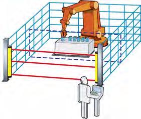
5 GuardShield PAC Safety Light Curtain Introduction The GuardShield PAC safety light curtain is a multiple beam, presence sensing device designed for perimeter or access detection around hazardous machinery or equipment The GuardShield PAC is a Type 4 AOPD per IEC It is a self contained, optically synchronized, two box (transmitter and receiver) safety light curtain with dip switch selectable operating modes. The GuardShield PAC safety light curtain consists of a nonmatched pair of optic units, i.e., transmitter and receiver. The transmitter and receiver operate on +24V DC. The maximum distance between transmitter and receiver is referred to as the protective field width or range. The protective field height is the distance between the first and last beam in the device. The transmitter emits sequential pulses of infrared light which are received and processed by the GuardShield PAC receiver. The synchronization of the timing of the emission and reception of infrared light pulses is accomplished optically by the first beam adjacent to the GuardShield PAC status LEDs. This beam is referred to as the synchronization beam. Because the GuardShield PAC transmitter and receiver are optically synchronized, no electrical connection is required between the transmitter and receiver. The GuardShield PAC receiver has two safety outputs, Output Signal Switching Devices (OSSDs) and one nonsafety auxiliary output. When the GuardShield PAC transmitter and receiver are properly powered and aligned, all OSSDs are current sourcing +24V DC with a switching capacity of 500 ma. The two safety OSSDs are cross monitored and short-circuit protected. Interruption of the sensing field causes the receiver to switch the sourced current OFF (0V DC). Restoring the GuardShield PAC sensing field, (in Guard only configuration) causes all outputs (OSSDs) to switch to the active high state (resume current sourcing +24V DC with a switching capacity of 500 ma). The GuardShield PAC is offered in a number of configurations based on a standard Type 4 safety light curtain platform. In addition to the standard GuardShield PAC, the GuardShield PAC is offered with an integrated laser alignment system or with an integrated laser alignment system with connectivity to ArmorBlock Guard I/O. The ArmorBlock Guard I/O optim allows network connectivity providing OSSDs over a DeviceNet or DeviceNet safety network. The ArmorBlock Guard I/O option is only available in GuardShield PACs with integrated laser alignment systems. Selectable functions of the GuardShield PAC and GuardShield PAC with integrated laser alignment are: Beam coding EDM (External Device Monitoring) Start interlock Restart interlock Selectable functions of GuardShield PAC with ArmorBlock Guard I/O connectivity: Beam coding Range of Uses of the Device The GuardShield PAC safety light curtain is classified as electrosensitive protective equipment (ESPE). The maximum protective field width is 16m (52.5ft) for the GuardShield PAC. The device is a Type 4 ESPE as defined by IEC and CLC/TS and is therefore allowed for use with controls in safety category Type 4 in compliance with EN ISO 13849, SIL CL3 in accordance with EN or up to PLe in accordance with EN ISO The device is suitable for: Hazardous area protection Access protection Access to the hazardous point must be allowed only through the protective field. The machine/system is not allowed to start as long as personnel are within the hazardous area. Refer to the Examples of Range of Use on page 6 for an illustration of the protection modes. The GuardShield PAC is intended as a perimeter or access protection device for a whole body detection and can not be used in horizontial detection applications as it may be possible for personnel to step between the beams and access the hazard without being detected. Depending on the application, mechanical protection devices may be required in addition to the safety light curtain. These installation instructions are designed to address the technical personnel of the machine manufacturer and or the installer of the safety system regarding the proper mounting, configuration, electrical installation, commissioning, operation and maintenance of the GuardShield safety light curtain. These installation instructions do not provide instruction for the operation of machinery to which the GuardShield safety light curtain is, or will be, integrated. Only qualified personnel should install this equipment. Additional measures may be necessary to ensure that the ESPE does not fail to danger when other forms of light radiation are present in a particular application (i.e., use of cableless control devices on cranes, radiation from weld spatter or effects from strobe lights). GuardShield PAC Laser Alignment The laser light source in the integrated laser alignment system of the GuardShield PAC light curtains is a Class 1, eye safe laser diode with a wavelength of 670 nm. 3
6 This Class 1, eye safe laser is switched from a low output power state to a high output power state (and back again) by means of control circuitry which detects reflected laser light from a temporary blockage of the emitted laser light. This is most commonly accomplished by a person s finger placed over the laser overlay window. There is also an automatic shutdown feature that switches the laser diode from the high power state to the low power state, if there is no finger or other interruption detected for a period of five minutes. During the high output mode of operation, the laser is pulsed at a rate of approximately 2 Hz in order to facilitate finger detection in high ambient light conditions. ATTENTION Safety Precautions Use of controls or adjustments or performance of procedures other than those specified herein, may result in hazardous radiation exposure. Principles for Safe Use and Symbols Used The following instructions are preventive warnings to ensure the safe and proper operation of the GuardShield PAC. These instructions are an essential part of the safety precautions and therefore have to be observed at any time. Throughout this manual we use the labels ATTENTION and to alert you to the following: ATTENTION Failure to observe may result in dangerous operation ATTENTION: Identifies information about practices of circumstances that can lead to personal injury or death, property damage, or economic loss. ATTENTION helps you Identify a hazard Avoid a hazard Recognize the consequences : Identifies information that is especially important for successful application and understanding of the product. ATTENTION Potentially hazardous situation, which, if not prevented, might lead to serious or deadly injury. Failure to observe may result in dangerous operation. ATTENTION The GuardShield PAC must not be used with machines that cannot be stopped electrically in an emergency. The safety distance between the GuardShield and a dangerous machine movement has to be maintained at all times. Additional mechanical protective devices have to be installed in a way that hazardous machine elements cannot be reached without passing through the protective field. The GuardShield has to be installed in a way that operators can only operate within the sensing area. Improper installation can result in serious injury. Never connect the outputs to +24V DC. If the outputs are connected to +24V DC, they are in ON-state and cannot stop hazardous spots at the machine/application. Never expose the GuardShield to flammable or explosive gases. Regular safety inspections are imperative (see maintenance). Do not repair or modify the GuardShield. The GuardShield safety light curtain is not field repairable and can only be repaired at the factory. Removal of either of the GuardShield endcaps will void the warranty terms of this product. Specialist Personnel The GuardShield PAC safety light curtain must be installed, commissioned and serviced only by a qualified person. A qualified person is defined as a person who: Has undergone the appropriate technical training and Who has been instructed by the responsible machine operator in the operation of the machine and the currently valid safety guidelines and Who has read and has ongoing access to these installation instructions Proper Use The GuardShield PAC safety light curtain must be used only as defined in the Range of Uses of the Device. It must be used only by qualified personnel and only on the machine where it has been installed and initialized by qualified personnel. If the device is used for any other purposes or modified in any way, warranty claims against Allen-Bradley Guardmaster shall become null and void. General Protective Notes and Protective Measures Safety Notes Please observe the following items in order to ensure the proper and safe use of the GuardShield safety light curtain. 4
7 The national/international rules and regulations apply to the installation, use and periodic technical inspections of the safety light curtain, in particular: Machine Directive 98/37/EEC Equipment Usage Directive 89/655/EEC The work safety regulations/safety rules Other relevant health and safety regulations Manufacturers and users of the machine with which the safety light curtain is used are responsible for obtaining and observing all applicable safety regulations and rules. The notices, in particular the test regulations of these installation instructions (e.g. on use, mounting, installation or integration into the existing machine controller) must be observed. The tests must be carried out by specialist personnel or specially qualified and authorized personnel and must be recorded and documented to ensure that the tests can be reconstructed and retraced at any time. The installation instructions must be made available to the user of the machine where the GuardShield PAC safety light curtain is installed. The machine operator is to be instructed in the use of the device by specialist personnel and must be instructed to read the installation instructions. referred to as the synchronization beam. Because the GuardShield PAC s transmitter and receiver are optically synchronized, no electrical connection is required between the transmitter and receiver. The GuardShield PAC s receiver has two safety outputs, OSSDs (Output Signal Switching Devices) and one nonsafety auxiliary output. When the GuardShield PAC s transmitter and receiver are properly powered and aligned, all OSSDs are current sourcing +24V DC with a switching capacity of 500mA. The two safety OSSDs are cross monitored and short-circuit protected. Interruption of the sensing field causes the Receiver to switch the sourced current Off (0V DC). Restoring the GuardShield PAC s sensing field, (in Guard only configuration) causes all outputs (OSSDs) to switch to the active high state (resume current sourcing +24V DC with a switching capacity of 500mA). The GuardShield PAC Light Curtain The GuardShield PAC safety light curtain consists of a transmitter and a receiver. Transmitter Receiver Product Description This section provides information on the special features and properties of the safety light curtain. It describes the structure and functions of the unit, in particular the different operating modes. Please read this section before mounting, installing and commissioning the unit. Special Features Start interlock Restart interlock External Device Monitoring (EDM) Machine test signal Beam coding GuardShield Light Curtain Principle of Operation The GuardShield PAC safety light curtain consists of a nonmatched pair of optic units, i.e. transmitter and receiver with the same number of beams and spacings. The transmitter and receiver operate on +24V DC. The maximum distance between the transmitter and receiver is referred to as the protective field width or range. The protective field height is the distance between the first beam and the last beam in the device. The transmitter emits sequential pulses of infrared light, which are received and processed by the GuardShield PAC receiver. The synchronization of the timing of the emission and reception of infrared light pulses is accomplished optically by the first beam adjacent to the GuardShield PAC s status LEDs. This beam is Figure 1: Components of the GuardShield PAC The individual beams of the GuardShield PAC are identified by markings on the housings. The width of the protective field is derived from the length of the light path between sender and receiver and must not exceed the maximum rated width of the protective field 16 m (52.5 ft). The GuardShield PAC is also offered with an integrated laser alignment system which has a constantly powered Class 1, eye safe laser located in the top of the GuardShield PAC transmitter and in the bottom of the GuardShield PAC receiver. Each Class 1, eye safe laser emits a low level of visible light. Simply blocking this light below the finger symbol causes the light to be reflected back to a photo sensor which changes the condition of the laser light. If this light is at a low level, interrupting it will cause the laser to emit a highly visible level of light. Interrupting the visible light in the same location will cause the laser to switch to a low level of emission. The emission of visible light will also change to a low level after five minutes of activation. Across from each laser is a target used to help with the alignment of the GuardShield PAC pair. Positioning the visible light in the center of the top and bottom targets will position the GuardShield PAC pair for optimal alignment. 5
8 Examples of Range of Use The GuardShield PAC safety light curtain operates as a proper protective device only if the following conditions are met: The control of the machine must be electrical. The controlled machine must be able to be stopped any where in the machines stroke or cycle. The transmitter and receiver must be mounted such that access to the hazard is only through the light curtain s protective field. The restart button must be located outside the hazardous area such that it cannot be operated by a person working inside the hazardous area. The statutory and local rules and regulations must be observed when installing and using the device. Safety Functions The GuardShield PAC safety light curtain offers a variety of functions, which are integral to the system. Operating modes, functions and features of the GuardShield PAC system are activated through dip switch settings. Guard Only When in the guard only mode of operation, the light curtain operates as an on/off device, meaning the OSSD outputs switch off/on according to an obstruction or clearing of the detection field. The GuardShield PAC is shipped from the factory in the guard only mode. Start Interlock The start interlock prevents the OSSD outputs from switching to ON state after power up of the system with the protective field unobstructed. A manual reset of the system is required for the GuardShield PAC to enter the ON state. This can be accomplished by one of two methods. Actuation of a momentary N.O. push button Interruption and restoration of the protective field within one second. Activation of this mode of operation and selection of the resetting method is through dip-switch settings. Indication of this mode of operation is through illumination of a yellow LED on the GuardShield PAC s receiver. Restart Interlock The protective system must be tested for proper operation after each and every change to the configuration. Start interlock is not available in GuardShield PAC light curtains with ArmorBlock Guard I/O connectivity. The restart interlock mode of operation prevents the OSSD outputs from switching to ON after interruption and clearance of the protective field. A manual reset of the GuardShield PAC system is required. Resetting of the system is accomplished through a momentary N.O. push button or key switch. Configuration and activation of this mode of operation is through dip-switch settings. The Restart Interlock mode is indicated by the illumination of a yellow LED on the GuardShield PAC s receiver. External Device Monitoring (EDM) or Machine Primary Control Element (MPCE) Monitoring The External Device monitoring function (EDM) is an input signal to the GuardShield receiver from the Final Switching Device (FSD), usually relay contactors, which control the hazardous motion of equipment or machinery. The EDM circuit is required to see a change of state of the FSD within 300ms of the restoration of the GuardShield s sensing field after its interruption. Detection of an unsafe condition such as a welded contact causes the GuardShield receiver to go to a lockout condition (OSSDs OFF). The activation and use of this GuardShield functionality usually allows the GuardShield s OSSDs to be connected directly to a machine s FSD and attain a Category 4 safety circuit. It is necessary to have the EDM circuit connected to two separate FSDs which are wired in series to attain the Category 4 rating. Activation of this functionality is accomplished by setting the EDM dipswitch no. three to the OFF position and then performing the Teach function. It is also necessary to connect the GuardShield receiver s EDM (yellow) wire to a N.C. output from the FSD. System Testing It is not possible to have both Start Interlock and Restart Interlock configured at the same time in the GuardShield PAC. Configuring Restart Interlock behaves the same as Start Interlock at power up, i.e., a reset of the system is required at power up. Restart interlock should always be configured for the GuardShield PAC light curtains. The reset switch should be located outside of the work cell and positioned so that a clear view of the work cell is possible. Restart interlock is not available in GuardShield PAC light curtains with ArmorBlock Guard I/O connectivity. this functionality must be configured and through the safety PLC. EDM is not available in GuardShield PAC light curtains with ArmorBlock Guard I/O connectivity. The GuardShield PAC performs a complete system self-test at power up and switches to the ON state if the system is properly aligned and the protective field is unobstructed and the start/ restart interlock modes of operation are deactivated. External Test (Machine Test Signal) A test cycle of the system can be triggered by an external test signal to the GuardShield PAC s transmitter. Supplying or removing a signal (+24V DC) via a N.C. or N.O. switch at the test input deactivates the transmitter for the duration of the test signal, simulating an interruption of the protective sensing field. 6

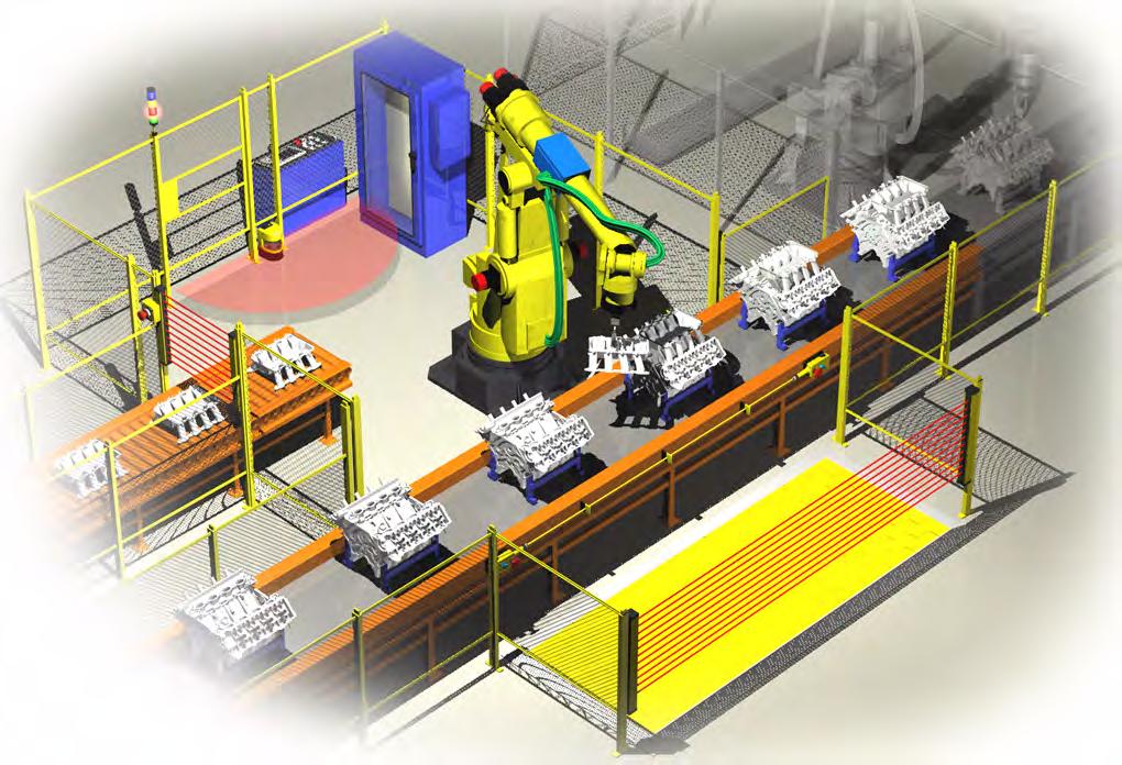
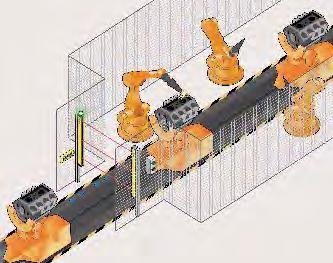
9 The test input must be configured via a dip-switch located in the GuardShield PAC transmitter. Beam Coding If several safety light curtains are operating in close proximity to one another, it is possible that the transmitter s infrared light from one GuardShield PAC system is seen by another GuardShield PAC system s receiver. This would cause a nuisance stop. To prevent this optical interference, the GuardShield PAC has the ability to have the transmitter generate different beam patterns, which is referred to as Beam coding. Selection and activation of beam coding is accomplished through dip-switch settings in both the transmitter and receiver. The following settings are available in the GuardShield PAC safety light curtain; noncoded and coded. Applications and Application Requirements Applications Beam coding improves resistance to optical interference. Beam coding increases the system s response time, which may also increase the required safety distance. Refer to Safety Distance calculations on page 9 of this manual. The GuardShield PAC multi-beam safety light curtain may be used as an opto-electronic fence; detecting the presence of personnel as they pass through the sensing field or for safeguarding access to a hazardous area or machine process. Used in combination with corner mirrors, the GuardShield PAC multi-beam safety light curtains provide multiple-side access detection. When using corner mirrors to protect multiple sides of a machine or work cell, the GuardShield PAC with integrated laser alignment is the preferred solution. Activation of visible laser light allows positioning and adjustment of the transmitter, receiver and corner mirrors. A typical system configuration for access detection to a hazardous area or machine process is to have the GuardShield PAC multibeam safety light curtain connected to an external module along with two or four sensors. The external module allows material to pass through the GuardShield PAC multi-beam s sensing field without stopping the machine or equipment as long as the muting conditions are met. As the material is moving through the process, the GuardShield PAC multi-beam s sensing field is interrupted and the outputs switch to the OFF state. However, if the muting module sensors are interrupted with the proper timing, the module disregards the GuardShield PAC multi-beam s outputs and remains in the ON condition, allowing the machinery or equipment to continue operation. If the muting sensors are not interrupted and maintained in the required timing and or sequence, the muting module will switch OFF when the GuardShield PAC multi-beam s sensing field is interrupted. Figure 2 is an example of a GuardShield PAC three-beam safety light curtain used as an opto-electronic fence with corner mirror columns. Figure 3 is an example of a GuardShield PAC three beam with four retroreflective sensors and an external muting module. Figure 2: GuardShield PAC three beam with corner mirror columns Work Piece GuardShield PAC Transmitter Corner Mirror Muting Module Figure 3: GuardShield PAC three beam with muting module Application Requirements GuardShield PAC Receiver Work Piece Roller Work Path Power Supply The protective functions of the PAC can only be used properly when the following conditions are satisfied: The machine or installation must be controlled electrically. It must be possible to stop hazardous machine movement. The PAC must be installed so that entry into the danger zone interrupts one or more of the light beams. The light beam diameter of 23 mm (0.90 in.) must be fully covered, to assure a change in state of outputs. Release can only be achieved with the use of a restart switch. The restart switch must be located such that it cannot be pressed from inside the danger zone. The GuardShield PAC should be mounted such that upon interruption of the light beam, the dangerous location can only be reached if the dangerous condition of the machine has been stopped. The requirement for this is that there is a proper safety 7
10 distance between the light beams and the nearest point of danger. Persons situated inside the danger zone, but outside the protection field are not recognized. It must therefore be ensured that a dangerous condition is only possible when there is nobody present in the danger zone. The relevant legal and government regulations are to be complied with the implementation of protection installations. These regulations vary, depending on areas of application. Corner Mirrors and Mounting Columns The GuardShield two- and three-beam PACs can be used with one or two corner mirrors to provide two- or three-sided protection. The use of each corner mirror reduces the maximum range of the GuardShield PAC by at least 10% per mirror. It is possible to use full length corner mirrors (440L-AM075 series, 440L-AM125 series). Rockwell also offers pedestal floor mounting stands (440L- AMSTD) which will accommodate the mounting of the GuardShield two- or three-beam PAC with the appropriate full length corner or mirror column mirrors. Mounting Stand with Corner Mirror Transmitter Mounting Stand with Corner Mirror Receiver Transmitter Receiver Configuration is not allowed. Mounting Stand with Corner Mirror Transmitter Receiver Figure 4: Multi-sided access control to danger zones with PAC multibeam safety light barrier 8
11 Determining Stop Time: The measurement of stopping time (Ts) must include the stopping times of all devices in the stop circuit. Not including all device and control system elements when calculating Ts will result in an inaccurate safety distance calculation. Determining the Safety Distance The light curtain must be mounted with proper safety distance From the point of danger From reflecting surfaces Figure 5: GuardShield three-beam PAC and corner mirrors mounted to pedestal floor stands US Safety Distance Formula ATTENTION The GuardShield PAC safety light curtains must be mounted at a sufficient distance from the hazardous motion to ensure that the machine stops before a person s body reaches the hazard. This distance, referred to as the safety distance, must be properly calculated prior to mounting the light curtains around the machinery. Failure to properly calculate this safety distance may result in operator injury. In the United States there are two formulas that are used to properly calculate the safety distance. The first, the OSHA formula, is the minimum requirement for the calculation of the safety distance. The second formula, the one recommended by Rockwell Automation, is the ANSI formula, which incorporates additional factors to be considered when calculating the safety distance. OSHA Safety Distance Calculation Formula The OSHA safety distance formula as specified in CFR Subpart O is as follows: Figure 6: GuardShield two-beam PAC and corner mirrors mounted to pedestal floor stands Figures 5 and 6 show two- and three-beam GuardShield PACs with two corner mirrors providing three-sided detection. Mirrors are offered in either narrow or wide styles in heights to accommodate two- or three-beam GuardShield PACs. Ds = 63 X T S Ds Safety Distance 63 Is the OSHA recommended hand speed constant in inches per second Ts Is the total stop time of all devices in the safety circuit, measured in seconds. This value must include all components involved in stopping the hazardous motion of the machinery. For a mechanical power press it is the stopping time measured at approximately the 90º position of the crankshaft rotation. Response Time The response time of the two- and three-beam GuardShield PAC safety light curtain is 20 ms without beam coding or 30 ms with beam coding. 9
, the machine s control circuit and any other devices that react to stop the")
12 The ANSI Safety Distance Formula The ANSI safety distance formula, which is the Rockwell Automation recommended formula, is as follows: Ds K Ts Tc The T S number must include the response times of all devices, including the response time of the safety light curtain, the safety light curtain controller (if used), the machine s control circuit and any other devices that react to stop the hazardous motion of the machinery. Not including the response time of a device or devices in the stop time calculation will result in insufficient safety distance for the application. This may result in operator injury. D S = K x (T S + T C + T r + T bm ) + D pf Minimum safety distance between the safe guarding device and the nearest point of operation hazard, in inches. Hand speed constant in inches per second. The ANSI standard value is 63 in. per second when the operator begins reaching toward the point of operation hazard from rest. NOTE: ANSI B E states The value of the hand speed constant, K, has been determined by various studies and although these studies indicate speeds of 63 inches/second to over 100 in./second, they are not conclusive determinations. The employer should consider all factors, including the physical ability of the operator, when determining the value of K to be used. Stop time of the machine tool measured at the final control element. Response time of the control system Ds= 63 in./sec X ( ) + 48 in. Ds = in in. Ds = in. from hazardous motion The GuardShield three beam PAC should be mounted at least 68.2 in. from the closest reachable hazard point of the protected machinery or equipment. European Safety Distance Formula A safety distance must be maintained between the light curtain and the point of danger. This safety distance ensures that the point of danger can only be reached after the dangerous state of the machine has been completely removed. The safety distance as defined in EN ISO and EN ISO depends on: Stopping/run-down time of the machine or system. (The stopping/run-down time is shown in the machine documentation or must be determined by taking a measurement.) Response time of the protective device The person s speed of approach Resolution of the light curtain and/or beam separation When using the GuardShield PAC three beam with 400 mm beam spacing, EN 999 requires that the first beam should be mounted at 300 mm above the floor. When mounted in this configuration, it is necessary to add 850 mm as the value for C in the safety distance calculation equation. Note: Tr Tbm Dpf T s and T c are usually measured by a stop time measuring device. Response time of the presence sensing device (safety light curtain) and its interface, if any. This value is generally stated by the device manufacturer or it can be measured by the user. Additional time allowed for the brake monitor to compensate for variations in normal stopping time. Depth penetration factor. It is an added distance to allow for how far into the protective field an object, such as a finger or hand, can travel before being detected. D pf is related to the safety light curtain s object sensitivity. Object sensitivity is the smallest diameter object which will always be detected anywhere in the sensing field. Figure 7: Safety distance from the point of danger Example Reach Over In this example, the value of K is the hand speed constant of 63 in. per second, the Ts machine stop time is 250 ms (0.250 sec), the 20% brake wear factor is 0.05 sec and the GuardShield PAC response time is 20 ms (0.020 sec). The Dpf is 48 in. for reach over applications. 10
 + 850 mm S = 1600 x (0.")
13 How to Calculate the Safety Distance S According to EN ISO and EN ISO 13857: First, calculate S using the following formula: S = 1600 (Ts + Tr) + C Where Ts = stopping/run-down time of the machine + response time of the protective device [s] Tr = response time of the GuardShield PAC S = safety distance [mm] C = safety supplement S = 1600 x ( ) mm S = 1600 x (0.270) mm S = mm S = 1282 mm Minimum Distance from Reflecting Surfaces The infrared light from the sender may be reflected off of shiny surfaces and be received by the system s receiver. If this condition occurs, it can result in an object not being detected when it enters the GuardShield PAC s sensing field. All reflecting surfaces and objects (e.g. material bins) must therefore be located at a minimum distance a from the protective field of the system. The minimum distance a depends on the distance D between sender and receiver. Distance D (meters) Figure 8: Minimum distance from reflecting surfaces How to Determine the Minimum Distance from the Reflecting Surfaces: Determine the distance D [m] sender-receiver Read the minimum distance a [mm] from the graph: a The effective aperture angle for the GuardShield PAC system is +/- 2.5 at a mounting distance of > 3.0 m (9.8 ft). Calculate the minimum distance to reflecting surfaces depending on the distance between the transmitter and the receiver, using an aperture angle of +/- 2.5, or take the appropriate value from the following table: Note: Distance Between Transmitter and Receiver (Range L) [m (ft)] Note: formula: a = tan 2.5 x D [mm] a = minimum distance to reflecting surfaces D = distance between transmitter and receiver Installation and Mounting Minimum Distance a [mm (in.)] 0.2 to 3.0 (0.65 to 9.8) 135 (5.31) 4.0 (13.1) 175 (6.88) 5.0 (16.4) 220 (8.66) 6.0 (19.6) 265 (10.43) 7.0 (22.9) 310 (12.2) 10.0 (32.8) 440 (17.32) 16.0 (52.4) 700 (27.55) This section describes the preparation, selection and installation of the GuardShield PAC safety light curtain. The GuardShield PAC safety light curtain is suitable for most operating environments (IP65 environmental rating). Proper safety distance must be observed. The installation of the GuardShield PAC safety light curtain must adhere to the ANSI standard B11.19/E , which requires that a presence sensing device shall prevent the operator or others from reasonably reaching over, around, or under the sensing field into the hazardous area. Auxiliary safeguarding may be required in conjunction with the GuardShield PAC to meet this requirement. Determine if the machinery, on which the GuardShield PAC is to be mounted, meets the requirements as specified in the beginning of this manual, i.e., machinery must be able to be stopped anywhere in its stroke or cycle, consistently and repeatedly. The GuardShield PAC must be mounted at the proper distance from the point of operation hazard. This distance is referred to as the Safety Distance. Figure 9: Graph, minimum distance from reflecting surfaces ANSI/RIA requires that the first beam of the GuardShield PAC be mounted at 300 mm (12 in.) off of the floor in vertical applications. The protective height of the GuardShield PAC three beam is 820 mm. The combination of 300 mm (12 in.) and 820 mm equals 1120 mm which meets the ANSI/RIA requirements of a reach over application. This requires that the depth penetration factor (Dpf) be 48 in. when performing the safety distance calculation. 11
14 The standard GuardShield PAC has an LED in the receiver which is used as an alignment aid. This LED will begin flashing when the infrared light from the transmitter is seen by the receiver. This LED turns off when optimal alignment is attained. An external laser (440L-ALAT) and mounting bracket (440L-AF6109) is offered as an accessory for aligning the GuardShield PAC. Alignment Procedure: Standard GuardShield PAC Mount and connect both transmitter and receiver. They must be parallel to each other and be positioned at the same height. Turn on power to GuardShield PAC system. Rotate the Transmitter while watching the amber LED on the receiver to find the point where the indicator for the ON state (Green LED) illuminates and the amber LED goes off. Determine the maximum left and right turning angles and position unit in center. Tighten all hardware assuring that the alignment indicator is not illuminated. Cycle power to assure that the system powers up and goes to the ON state (alignment indicator is OFF) The GuardShield PAC meets the requirements of IEC which requires that the optics of the transmitter and receiver emit and receive infrared light at a maximum of +/-2.5. This requirement creates a tight optical path of infrared light and as such may make the GuardShield PAC somewhat difficult to align at maximum range or when corner mirrors are being used in the application to provide two or three sided perimeter guarding. When using the GuardShield PAC in perimeter guarding applications, particularly with corner mirrors, it is best to use the Allen Bradley GuardMaster laser alignment tool to ease the alignment process. The laser alignment tool part number is 440L- ALAT. It is also necessary to use the GuardShield mounting bracket (440L-AF6109) to mount the laser alignment tool to the GuardShield PAC housing The GuardShield PAC is also offered with an integrated laser alignment system. Select the appropriate cat. nos. for this model of GuardShield PAC. Alignment Procedure for GuardShield PAC with Integrated Laser Alignment 1. Properly locate the GuardShield PAC pair from the point of operation hazard after performing the safety distance calculation. 2. Using the GuardShield PAC mounting brackets, mount the transmitter and receiver so that they are facing one another and are positioned in the same direction. A reference would be that the indicator LEDs are opposite one another. 3. Turn on each laser by placing a finger or hand in front of each laser. 4. Adjust the transmitter and receiver in such a way that both visible laser beams hit the laser targets opposite each laser. A small deviation from the center of the target is allowable. Multiple GuardShield PACs When two or more GuardShield PACs are mounted in close proximity to one another, it may be possible for the receiver of one GuardShield PAC pair to receive infrared light from the transmitter of another GuardShield PAC pair. This optical interference can be over come by the GuardShield PAC feature of Beam Coding. Beam coding changes the pulse pattern of infrared light emitted by a GuardShield PAC transmitter. Noncoded Figure 5: Multiple GuardShield PAC alignment options Mounting Brackets Coded Transmitters emit in opposite direction. Each receiver receives only the beams of the appropriate transmitter. Transmitters emit in same direction: Coding necessary Positioning of the light curtain: Transmitters emit in opposite direction. The GuardShield PAC is mounted using right angle brackets attached to the endcaps of both transmitter and receiver. Each GuardShield PAC is supplied with standard right angle mounting brackets and self-threading screws. It may be necessary to use additional brackets to mount the GuardShield PAC at a proper safety distance from the machinery hazard. 12
 Figure 6: Mounting brackets Shock Isolation Kits Rockwell Automation offers a shock and vibration isolation kit (440L-AF6120) for attenuating excessive shock and vibration in vertical")
15 20 (0.79) 52 (2.04) 42 (1.65) 18.9 (0.74) 14.5 (0.57) 3.0 (0.11) 40 (1.57) 6.5 (0.26) 32 (1.25) Figure 6: Mounting brackets Shock Isolation Kits Rockwell Automation offers a shock and vibration isolation kit (440L-AF6120) for attenuating excessive shock and vibration in vertical applications of the GuardShield PAC safety light curtain. This kit is most effective in extending the operational life of the GuardShield PAC safety light curtains in excessive shock and vibration applications, particularly in applications where shock levels can exceed 50 g. Figure 7: Shock isolation kit Horizontal Application Vertical Application Rockwell Automation also offers pedestal floor stands for mounting the GuardShield light curtains when the shock and vibration levels of the equipment are excessively high. These mounting stands isolate the GuardShield light curtains from receiving the shock through the equipment, however, the area immediately around the machine may also experience high levels of shock and vibration therefore, it may be necessary to use the shock mount kits when mounting the light curtains to the mounting stands. Figure 8: Pedestal floor stand Electrical Installation Connections Power Supply The external voltage supply (+24V DC) must meet the requirements of IEC In addition, the following requirements have to be fulfilled: A short-term power failure of 20 ms must be bridged by the power supply. The power supply has double insulation between the primary and the secondary side. The power supply is protected against overload. The power supply corresponds to the guidelines of the EWG (industrial environment). The power supply corresponds to the Low Voltage Directives. The grounded conductor of the power supply device must be connected to a grounded conductor PE. The maximum deviation of the voltage levels is 24V DC +/- 20%. 13
![Double Insulation Connections [mm (in.)] Output (pink and grey) Basic Insulation (see note) Basic Insulation 42 (1.](/docs-images/74/71065286/images/16-1.jpg "7) Guard Shield Re-inforced insulation or double insulation 0V (blue) +24V (brown) Unit 1 EDM Connection Transmitter Hazardous voltage level K1 K1 K2 Power Supply Unit 2 Hazardous voltage level K2")

16 Double Insulation Connections [mm (in.)] Output (pink and grey) Basic Insulation (see note) Basic Insulation 42 (1.7) Guard Shield Re-inforced insulation or double insulation 0V (blue) +24V (brown) Unit 1 EDM Connection Transmitter Hazardous voltage level K1 K1 K2 Power Supply Unit 2 Hazardous voltage level K2 Motor, etc. Hazardous voltage level Basic Insulation Receiver Cables/Connectors The GuardShield PAC transmitter connector is a four-pin DC micro connector offered in cable lengths from 2 to 30 meters. The GuardShield PAC receiver connector is an 8-pin DC micro connector offered in cable lengths of 2 to 30 meters. GuardShield PAC Standard and GuardShield PAC with ArmorBlock Guard I/O Connectivity Transmitter Connection Face View of Female DC Micro Color Pin No (0.57) Signal Transmitter Brown 1 +24V DC White 2 No Connection Blue 3 0V DC Black 4 Machine Test Signal 24V Pin 4 5 k2 k1 Contacts Contacts 6 Figure 9: Connecting the contact elements to the EDM Transmitter Not available for GuardShield PAC with ArmorBlock Guard I/O connectivity. k1 Contactor Coils k2 Receiver Note: The transmitter is not expected to be connected to the ArmorBlock Guard I/O module. Standard GuardShield PAC Receiver Connector Receiver Connection Face View of Female DC Micro Color Pin No Signal Receiver White 1 Auxiliary Output Brown 2 +24V DC Green 3 Ground Yellow 4 EDM Grey 5 OSSD 1 Pink 6 OSSD 2 Blue 7 0V DC Red 8 Start/Restart GuardShield PAC Receiver Connector for ArmorBlock Guard I/O Connectivity Signal Reset/restart button Pin 8 24V Figure 10: Connecting the reset button/restart button Top View Color Pin No. Receiver Brown 1 +24V White 2 OSSD 2 Blue 3 0V Black 4 OSSD 1 Grey 5 NC Not available for GuardShield PAC with ArmorBlock Guard I/O connectivity. 14
17 GuardShield PAC Receiver Interconnecting Patchcords to ArmorBlock I/O Cat. No. 889D-F5ACDM-0M3 889D-F5ACDM-1 889D-F5ACDM-2 889D-F5ACDM-5 889D-F5ACDM-10 Description 5-pin M12 patchcord, 12 inches 5-pin M12 patchcord, 1 meter 5-pin M12 patchcord, 2 meters 6-pin M12 patchcord, 5 meters 7-pin M12 patchcord, 10 meters Typical Wiring Diagram Direct to Contactors +24V DC Transmitter Receiver S2 Start/Restart Brown Brown + Red Grey OSSD 1 L1 L2 L3 Machine Test Signal S1 Test 6 Pink OSSD 2 K2 Bulletin 100S Safety Contactors or 700S Safety Relays Black K1 Blue Yellow White (Aux cht) Blue - Green MPCE/EDM Auxiliary Signal M 24V Ground ➊ Nonsafety auxiliary output can be connected to a lamp, motor or status to a PLC. Note: If MPCE/EDM is activated in the GuardShield PAC, the application requires a safety contactor. If MPCE/EDM is not used K1 & K2 can be standard contactors. 15
18 Typical Wiring Diagram To MSR127 Safety Relay Module +24V Brown No Connection L1 L2 L3 1 Transmitter Brown Receiver 3 OSSD 1 OSSD 2 Blue 5 Grey 6 Pink 7 Blue K4 +24V A1 S52 MSR127 S K4 K5 A2 S21 S22 S K5 Reset K4 K5 M GuardShield Light Curtain Connected to MSR22LM with Two Sensor Muting +24V DC Power Maintained P/B START K1 K2 2 Brown 7 Blue Receiver 5 Grey 6 Pink 3 Blue Transmitter 1 Brown Muting Sensor 1 Muting Sensor 2 A1+ X44 S43 S44 S12 S14 S21 S22 S24 S23 S31 S32 S34 S33 S41 S42 MSR22LM 440R-P23071 A2- M1 M Muting Lamp K1 K2 Bulletin 100S Safety Contactors or 700S Safety Relays Restart Required Lamp DC Common 16
19 GuardShield Light Curtain Connected to MSR22LM with Four Sensor Muting +24V DC K Receiver 5 6 Transmitter START K2 Muting Sensor 3 Muting Sensor 4 Muting Sensor 1 Muting Sensor 2 NOTES: 1. Muting sensors are N.C. PNP type 2. Wire reset switch to S43 & S44 when external monitoring is not required. Terminal X44 is not used. 3. Muting lamp must meet the following current specs: Minimum current: 25 ma Maximum current: 100 ma A1+ X44 S43 S44 S12 S14 S21 S22 S24 S23 S31 S32 S34 S33 S41 S42 MSR22LM 440R-P23071 A2- M1 M Muting Lamp K1 K2 Bulletin 100S Safety Contactors or 700S Safety Relays Restart Required Lamp DC Common GuardShield Light Curtain Connected to MSR42/MSR45E with Two Sensor Muting +24V DC Brown 1 Brown 2 Blue 3 Blue Sen 2 Pink Grey OSSD 2 OSSD 1 MSR42 Lamp +24V GPIO 4 GPIO 3 GPIO 2 MSR45E Sen 1 Reset/MDO GPIO 1 23 IN 1 K1 EDM K2 IN 2 0V 24 K1 K2 0V DC Note: It is necessary to use the optical interface (445L-AF6150) to program the MSR42. 17
20 GuardShield Light Curtain Connected to MSR42 with Two Sensor Muting +24V DC Brown 1 Brown 2 3 Blue 7 Blue 6 5 Sen 2 Pink Grey OSSD 2 OSSD 1 MSR42 Lamp +24V GPIO 4 GPIO 3 GPIO 2 OSSD 2 Sen 1 Reset/MDO GPIO 1 K1 K2 EDM IN 1 OSSD 1 IN 2 0V K1 K2 Note: 0V DC It is necessary to use the optical interface (445L-AF6150) to program the MSR42. 18


21 System Configuration DIP-Switch Selection Settings Transmitter Receiver Factory Settings Switch Switch Function Default Setting 1 Mode Activation Combination ON Guard Only 2 activates one of the following modes: ON Guard only, Start interlock, Restart Interlock 3 MPCE Monitoring disable ON Disabled Description 4 Not used OFF 5 Not used OFF 6 Not used OFF DIP-Switch Selection Settings Receiver After mounting, electrically connecting and aligning the GuardShield PAC safety light curtain, it is now possible to configure your system. To begin system configuration, use the security tool provided to loosen the screw in the configuration door. Note: Note: Teach Button Door Status Switch The configuration door screw is a captive screw. The transmitter can only be configured for beam coding and Machine Test Signal. If neither of these configurations are required, then it is only necessary to configure the GuardShield PAC receiver. Identify and set the appropriate dip-switches for the configuration desired. Dip-switch identification and function is explained in the tables below. Follow the Teach Function Procedure to reconfigure the GuardShield PAC. After each reconfiguration of the GuardShield PAC, test the system for proper configuration and operation before placing the guarded machine in operation. When delivered from the factory, the following settings are configured. 7 Set Beam Coding OFF Disabled 8 Not used OFF Transmitter Factory Settings Switch Switch Function Default Setting Description 1 Set Beam Coding OFF Disabled 2 Machine Test Signal OFF OFF: Signal High active No connection or connect normally open ON: Signal Low active Connect N/C Settings for Mode of Operation Receiver Switch 1 Switch 2 Condition Operation ON ON Guard Only ON/OFF Operation OFF ON Start Interlock (Push Button Reset) OFF OFF Restart Interlock ON OFF Start Interlock ATTENTION Interlock at start up Reset by actuation of pushbutton switch Interlock at interruption of sensing area Reset by actuation of pushbutton switch Interlock at start up Reset by Interruption/ restoration of sensing area for <1 sec Every modification at the DIP switches must be stored in the memory of the device through the Teach function. Simply changing the position of a dip switch will not change the GuardShield. It is necessary to first change the dip switch position and then perform the teach function. If the changes have been enabled in the GuardShield, the amber LED will flash three times as a visual confirmation that the change has been accepted. GuardShield PAC light curtains with ArmorBlock Guard I/O connectivity are configured from the factory as standard GuardShield PAC light curtains. However, the only configurable functionality is beam coding. All other configurable functions have been disabled. 19
22 Teach Function Procedure: Step 1 Step 2 Step 3 Open cover of the end cap (LED blinks: Receiver is red LED, Transmitter is amber LED). Select the desired switch setting. Press and hold the Teach button. The yellow LED flashes at 10 Hz (10x per second). Step 4 The yellow LED will stop blinking while the button is depressed. After the yellow stops flashing, release the teach button within 2 seconds. After 3 flashes of the yellow LED the function is activated. Step 5 Close and secure the cover. The doors on the transmitter and receiver must be closed for the GuardShield PAC to operate. If the GuardShield PAC teach procedure is not properly completed, the unit will remain in the previous operating mode. Once the teach function is completed and the door secured, verify that the operating mode has changed to the intended mode. Troubleshooting Guide The light curtain carries out an internal self-test after startup. If an error occurs, an appropriate signal combination is sent through the LEDs to the transmitter and receiver. Condition No. Error Description Action 6 Internal fault, receiver Check configuration of transmitter and receiver Replace receiver 7 Internal fault, transmitter Check configuration of transmitter and receiver Check protective field transmitter/ receiver Check connections transmitter/ receiver Exchange transmitter 8 External fault Check connections of OSSD outputs for short circuit against +24V DC and GND (cable, connected devices) Exchange receiver 9 External fault (MPCE error) The function Relay monitoring is activated and after clearing the OSSD the input Relay monitoring does not recognize a change of state. Check connection Relay monitoring Check connected relay for closed contact (if OSSD ON input Relay monitoring must have GND level, if OSSD OFF input Relay monitoring must have +24V) Switch on only after POWER OFF/ON 10 Configuration mode (Receiver) Cover for DIP switch setting at the receiver is open 11 Configuration mode (Transmitter) Cover for DIP switch setting at transmitter is open 20
23 System Status Indicators Receiver Transmitter OSSDs OFF OSSDs ON Interlock Alignment Emitting POWER ON Receiver LEDs Transmitter LEDs Condition No. OSSDs OFF Red OSSDs ON Green Yellow Alignment Amber 6 through 11 = Fault conditions ➊ Data transmission factory configuration interface not available for use outside factory Flash rate is approximately. 2 Hz (2 times per second) Note: Note: For fault conditions 6 through 11, see Troubleshooting guide on page 20. Interlock 1 OFF ON OFF OFF OFF ON ON 2 ON OFF OFF OFF OFF ON ON 3 ON OFF OFF ON OFF ON ON 4 ON OFF OFF OFF ON ON ON 5 ON OFF OFF OFF OFF ON OFF 6 FLASH OFF OFF OFF OFF ON ON 7 ON OFF OFF OFF OFF FLASH ON 8 FLASH OFF OFF ON OFF ON ON 9 FLASH OFF OFF OFF ON ON ON 10 FLASH OFF DATA TRANS ➊ OFF OFF ON ON Yellow Power On Amber Emitting 11 ON OFF OFF OFF OFF FLASH DATA TRANS ➊ Condition No. Description 1 Guard only mode, light curtain unobstructed (aligned, not in interlock) 2 Guard only mode, light curtain interrupted (aligned, not in interlock) 3 Guard only mode, misaligned (not in interlock) 4 In start or restart interlock (aligned) 5 Transmitter test input active (pin 4) 6 Internal fault, receiver 7 Internal fault, transmitter 8 External fault (OSSD short to ground, +V, or cross connection) 9 External fault (MPCE/EDM error) 10 Configuration mode (receiver access door open) 11 Configuration mode (transmitter access door open) Yellow ATTENTION Assure that all power to the machine, and safety system is disconnected during electrical installation. 21
24 Checklist Prior to powering up the GuardShield PAC system, the responsible person should review the following Checklist. Before the initiation of the GuardShield PAC the responsible person should work through the following checklist. Cable check prior to initiation: 1. o The power supply is solely connected to the GuardShield PAC. 2. o The power supply is a 24V DC device, that must comply to all applicable standards of the Machinery Directive 2006/42/EC, and the product standard (IEC 61496). 3. o Proper polarity of the power supply at the GuardShield PAC. 4. o The transmitter connection cable is properly connected to the transmitter, the receiver connection cable is properly connected to the receiver. 5. o The double insulation between the light curtain output and an external potential is ensured. 6. o The OSSD outputs are not connected to +24V DC. 7. o The connected switching elements (load) are not connected to 24V DC. 8. o No connection to a conventional power supply. 9. o If two or more GuardShield PAC are to be used, make sure that each system is properly installed, in order to avoid optical interference. Daily Inspection 1. o Approach to hazardous machine parts must only be possible through the protective field of GuardShield PAC. 2. o Operators cannot step through the sensing area while working on dangerous machine parts. 3. o The safety distance of the application is bigger than the calculated value. 4. o The optic front cover is neither scratched nor dirty. Operate the machine and check, if the hazardous movement will stop under the following circumstances. 5. o The protective field is interrupted. 6. o Hazardous machine movement stops immediately, if the protective field is interrupted by the test rod directly in front of the transmitter, directly in front of the receiver and in the middle between transmitter and receiver. 7. o No hazardous machine movement while completely interrupting any of the PAC beams. 8. o The power supply of the GuardShield PAC is turned off. If any of the above conditions do not result in the hazardous motion of the machine ceasing, do not allow the protected machine to be placed in operation. Switch the GuardShield PAC on and check its function by observing the following: 10. o 2 seconds after switching on, the system starts to work properly, if the protective field is free of obstructions. Safety Instructions Maintenance ATTENTION Never operate the GuardShield PAC before carrying out the following inspection. Improper inspection can lead to serious or even deadly injury. Note: 1. For safety reasons all inspection results should be recorded. 2. Only persons, who clearly understand the functioning of the GuardShield PAC and of the machine, may carry out an inspection. 3. If installer, planning engineer and operator are different people, make sure that the user has sufficient information available to carry out the inspection. 22
25 Six-Month Inspection Check the following items every six months or whenever a machine setting was changed. 1. o Machine stops or does not obstruct any safety function. 2. o The latest machine or connection modifications have no effect on the control system. 3. o The outputs of the GuardShield PAC are properly connected to the machine. 4. o The total response time of the machine is shorter than the calculated value. 5. o Cables and plugs of the GuardShield PAC are in flawless condition. 6. o Mounting brackets, caps and cables are tightly secured. Cleaning If the optic front cover of the GuardShield PAC is dirty, the outputs of the GuardShield PAC may turn off. Take a clean, soft cloth and rub without pressure. Do not apply aggressive, abrasive or scratching cleansing agents, which might attack the surface. Date Code Bul/Type 440L Part No. R4A2500YD Ref No. AA00AA00 Ser Rev A B Made in Jun, 2010 Ambient Temp C Power Consumption 7W max. Supply Voltage 24V DC +/-20% Safety Parameters Type 4/Cat.4 IEC61496/ EN ISO EN62061/ IEC61508 PLe/SIL CL3,SIL3 Operating Instructions PN GuardShield TM Rockwell Automation 2 Executive Dr. Chelmsford MA Degree of Protection IP # of Beams/Spacing Product of Mexico Electro-Sensitive 2/520mm Protective Equip. Range m 19KP Protective Height 500mm Bul/Type 440L Response Time with Coding <30ms Ser Rev Response Time w/o Coding Part No. <20ms R4A2500YD A B PAC Location of Manufacture Year of Manufacturer Week of Manufacturer X X* XX M or 4K R 02 M represented Manchester, NH replaced by 4K for Monterrey, Mexico * J=2004 K=2005 L=2006 M=2007 N=2008 P=2009 R=2010 S=2011 T=2010 U=2013 V=2014 W=2015 Y=2016 Z=2017 Figure 4: Explanation of data code 23
26 Technical Specifications Light Beams Protective Field Range Response Time 3/400 mm spacing (440L-P4A3400YD)2/500 mm spacing (440L-P4A2500YD) 820 mm (31.8 in.) 3 beam, 520 mm (20.4 in.) 2 beam 16 m (52.5 ft) OSSD ON to OFF: (Reaction times); 20 ms uncoded; 30 ms coded Power Supply 24V DC +/-20%; Power supply must meet the requirements of IEC and IEC Power Consumption IR Transmitter Aperture Angle Operating Condition 400 ma max. (unloaded) Infrared LED (wave length 870 nm) Within ± 2.5 for transmitter and receiver IR transmitter ON Functions Guard Only: On/Off operation with clear/obstructed detection area Start Interlock: Interlock at start up Reset by actuation of momentary N.O. pushbutton switch (or interruption/restoration of light curtain) Restart Interlock: Interlock at interruption of sensing field Reset by actuation of momentary N.O. pushbutton switch Relay Monitoring: Monitoring a switch contact of the installation Coding: May be necessary for multiplex alignment Test Function: Triggering of system test via external switch Inputs Transmitter Inputs Receiver Outputs: Status Indicators Receiver Status Indicators Sender QD Connectors Safety Outputs (OSSDs) Machine Test Signal Start/Restart Interlock MPCE Auxiliary Output ON-state OFF-state Alignment Interlock Power ON Emitting Minimum duration 100 ms Voltage level for Logic 0: 0 5V DC Voltage level for Logic Hi 1: > 16V DC Logic Lo Minimum duration 100ms; maximum duration 900 ms Voltage level for Logic Lo 0: 0 5V DC Voltage level for Logic Hi 1: > 16V DC 300 ms after activation of OSSD Voltage level for Logic 0: 0 5V DC Voltage level for Logic Hi 1: > 16V DC Two solid state outputs, max. switching capacity 500 ma (resistive/inductive), short circuit protected, max. residual voltage 2V (excl. voltage drop through cables) Solid state output, max. power consumption 500 ma (resistive/inductive), max. residual voltage 2V nonsafety output Max. Off State leakage current: 1 ma Max. Capacitive Load: 0.18 uf Constant ON when system is in ON-state (green LED) Constant ON when system is in OFF-state (red LED) Lights up at interruption of protective field or if fault occurs Lights up, if input signal is too weak (amber LED) Lights up when light curtain is in start or restart interlock mode (yellow LED) Lights up, when voltage is on (amber LED) Constant ON when transmitter is active (yellow LED) Transmitter: M12 plug 4 pin; receiver: M12 plug 8 pin for standard GuardShield PAC and PAC with integrated laser alignment system, GuardShield PAC with ArmorBlock I/O 5-pin M12 Cable Length Maximum 30 m (100 ft), Maximum resistance: 5 ohms Ambient Temperature During operation: C ( F); For storage: C ( F) Humidity of the Air Up to 95% (without condensation) between C ( F) Enclosure Rating IP65 Vibration Resistance Per IEC , IEC Frequency Hz Amplitude 0.35 mm Shock Per IEC , IEC Acceleration 10 g, Duration 16 ms Material Housing: Aluminum; Cover: PMMA (acrylic) Dimensions (cross section) Approx. 40 mm x 50 mm (1.57 in. x 1.96 in.) Accessories Included Mounting brackets, operating instructions, security tool, plastic tool for setting dipswitch and teach function Approvals IEC Parts 1and 2, UL Parts 1 and 2, UL 1998 Safety Classification Type 4 per EN/IEC 61496, category 4 EN/ISO 13849; SIL 3, IEC 61508, SIL CL3 EN 62061, PLe, EN/ISO PFHd (mean probability of a dangerous failure/hr Standalone sys.: 9.51 x 10⁻⁹ ; Cascading sys. (host/guest): 1.95 x 10⁻⁸ ; Cascading sys. (host/guest/guest): 2.75 x 10⁻⁸ T M (mission time) 20 years (EN ISO 13849) Transmitter Wave Length 870 nm 24
27 GuardShield PAC standard Note: Cat. No. Beam Spacing No. of Beams Protective Height [mm (in.)] 440L-P4A2500YD (20.4) 440L-P4A3400YD (32.2) GuardShield PAC light curtains are sold in pairs. To select a transmitter or receiver, replace the P in the cat. no. with a T for the transmitter and an R for the receiver. GuardShield PAC with Integrated Laser Alignment Note: Cat. No. Beam Spacing No. of Beams Protective Height [mm (in.)] 440L-P4AL2500YD (20.4) 440L-P4AL3400YD (32.2) GuardShield PAC with integrated laser alignment are sold in pairs. To select a transmitter or receiver, replace the P in the cat. no. with a T for the transmitter and an R for the receiver. GuardShield PAC with Integrated Laser Alignment and I/O Connectivity Note: Cat. No. Beam Spacing No. of Beams Protective Height [mm (in.)] 440L-P4AL2500YA (20.4) 440L-P4AL3400YA (32.2) GuardShield PACs with ArmorBlock Guard I/O Connectivity are sold in pairs. The pair consists of a standard GuardShield PAC with integrated laser alignment transmitter with 4 pin M12 quick-disconnect (440L-T4AXXXXYD). To select a receiver, replace the P in the cat. no. with an R for the receiver. Cat. No. Explanation 440L - P 4 A X XXX Y D PAC Category Type 4 P - Pair, T - Transmitter, R - Receiver Bulletin Number Connector Option Micro QD Environmental Rating IP65 Beam spacing (400mm or 500mm) Number of beams (2 or 3) 440L - P 4 A L X XXX Y A Connector Option ➊ Environmental Rating IP65 Beam spacing (400 or 500 mm) Number of beams (2 or 3) L = Integrated laser alignment system PAC Type 4 P - Pair, T - Transmitter, R - Receiver Bulletin Number ➊ D for M12 QD and A for 5-pin M12 for ArmorBlock Guard I/O 25
28 Bill of Material for 3-sided guarding using pedestal floor stands and corner mirrors with a GuardShield 3-beam PAC without cordsets. Qty. Description Cat. No. 1 GuardShield three-beam PAC pair 440L-P4A3400YD 2 Narrow 1050 mm corner mirror 440L-AM Wide 1050 mm corner mirror 440L-AM Pedestal floor stand 440L-AMSTD Dimensions [mm (in.)] 11 (0.43) 11 (0.43) 52 (2.05) 52 (2.05) 42 (1.65) 20 (0.79) 40 (1.57) A Protective Height [mm (in.)] 400 (15.75) B Mounting Value [mm (in.)] 500 (19.69) Protective Height A Protective Height A B C 400 (15.75) C Total Length [mm (in.)] Beam Location Indicator Beam Location Indicator 80 (3.14) min 820 (32.3) ± (42.4) 1112 ±1.5 (43.8) ± L-P4A2500YD 520 (20.5) ± (29.8) 792 ±1.5 (31.2) ± L-P4A3400YD 75 (2.95) 80 (3.14) min Cat. No. 440L-P4A2500YD 440L-P4A3400YD 26
29 11 (0.43) 42 (1.65) 52 (2.05) 400 (15.75) Protective Height 810 (31.89) (1.57) 40 (2.95) (1.58) 1192 (47.00) 1156 (45.51) 400 (15.75) Beam Location Indicator 440L-P4A3400YD consists of a pair 440L-T4A3400YD transmitter & 440L-R4A3400YD receiver 80 (3.14) min 20 (0.79) Receiver Transmitter 63.5 (2.50) 1066 (42.00) 11 (0.43) 42 (1.65) 52 (2.05) 500 (19.69) Protective Height 520 (20.47) Beam Location Indicator 80 (3.14) min Receiver (1.57) (2.95) 40 (1.58) 836 (33.00) 872 (34.33) 440L-P4A2500YD consists of a pair 440L-T4A2500YD transmitter & 440L-R4A2500YD receiver 20 (0.79) Transmitter 63.5 (2.50) 746 (29.37) 27
30 Accessories Corner Mirrors Narrow 8 x (1.96) Wide 8 x (1.96) 50 (1.96) 73 (2.87) 123 (4.84) L 396 (15.6) B 440 (17.32) %%P120%%D A 372 (14.64) Ls 340 (13.4) L 396 (15.6) B 440 (17.32) Ls 340 (13.4) A 372 (14.64) A A 114 (4.48) 13.3 (0.52) A 35 (1.37) 54 (2.12) A 10.5 (0.41) 2.5 (0.098) 75 (2.95) 44.4 (1.74) 4.5 (0.17) 6.5 (0.25) 164 (6.45) %%P120%%D 13.3 (0.52) 35 (1.37) 54 (2.12) 50 (1.96) 164 (6.45) 2.5 (0.098) 10.5 (0.41) 6.5 (0.25) 75 (2.95) 44 (1.74) 4.5 (0.17) Light Curtain Cat. No. 440L-P4A3400YD 440L-P4AL3400YD 440L-P4AL3400YA 440L-P4A2500YD 440L-P4AL2500YD 440L-P4AL2500YA Mirror Cat. No. Narrow 440L-AM Wide 440L-AM Narrow 440L-AM Wide 440L-AM GuardShield 2- and 3-beam light curtain PAC mounting and mirror columns Stand 440L-AMSTD 25.4 (1.0) 63.5 (2.5) (72) 11.1 (7/16) Dia (0.5) Dia. 4X (0.75) 6.35 (0.25) (12) 63.5 (2.5) 25.4 (1.0) Figure 5: Pedestal floor stand 76.2 (3.0) 76.2 (3.0) 6.35 (0.25) M10 x 1.5 mm Class 6g thru 4 pl (15) Note: Two GuardShield mounting brackets are supplied with each 440L-AMSTD floor stand. 28
] 440L-P4A2500YD 440L-AGWS0640 655.3 (25.8) 440L-P4A3400YD 440L-AGWS0960 975.4 (38.4) 440L-P4AL2500YD 440L-AGWS0800 815.3 (32.1) 440L-P4AL2500YA 440L-P4AL3400YD 440L-AGWS1120 1135.4 (44.")
31 GuardShield Washdown Enclosures GuardShield PAC Weld Shield PAC 440L-P4A3400YD 440L-P4A2500YD Cat. No. Enclosure Kit 440L-AGST L-AGST640 GuardShield PAC Cat. No. GuardShield Weld Shield Cat. No. Dimension L [mm (in.)] 440L-P4A2500YD 440L-AGWS (25.8) 440L-P4A3400YD 440L-AGWS (38.4) 440L-P4AL2500YD 440L-AGWS (32.1) 440L-P4AL2500YA 440L-P4AL3400YD 440L-AGWS (44.7) 440L-P4AL3400YA GuardShield PAC ArmorBlock Connectivity Note: Note: The GuardShield washdown enclosures are designed for use with standard GuardShield PAC light curtains only. Laser Alignment Tool (used on standard GuardShield) Requires 440L-AF6109 bracket to mount to front of GuardShield PAC 66.8 (2.63) (0.75) Top View Color Pin No Signal Receiver Brown V White 2 OSSD 2 Blue 3 0 V Black 4 OSSD 1 Gray 5 NC Example of Patchcord (2.46) 12.9 (0.48) 4 (0.15) Interconnecting Patchcords ArmorBlock I/O Connection Weld Shields Laser Alignment Tool (LAT) 440L-ALAT The GuardShield PAC weld shields are sold as pairs. These polycarbonate weld shields are designed as disposable devices whose purpose is to protect the front window of the GuardShield PAC from damage. Dimensions [mm (in.)] 3.0 (0.118) Thick 4.29 (0.169) hole dia. 81 x 2.66 (0.105) countersink (0.70) (1.4) (1.75) GuardShield PAC LAT Bracket 440L-AF (1.47) Cat. No. 889D-F5ACDM-0M3 889D-F5ACDM-1 889D-F5ACDM-2 889D-F5ACDM-5 889D-F5ACDM-10 Description 5-pin M12 patchcord, 12 inches 5-pin M12 patchcord, 1 meter 5-pin M12 patchcord, 2 meters 5-pin M12 patchcord, 5 meters 5-pin M12 patchcord, 10 meters The GuardShield PAC pair with ArmorBlock Guard I/O Connectivity has a five-pin M12 quick-disconnect connector on the receiver wired to connect to the ArmorBlock five-pin connector. The transmitter in that GuardShield pair is a standard GuardShield PAC transmitter with integrated laser alignment system offered with a four-pin M12 quick-disconnect connector. It is possible to connect either a standard four-pin M12 cordset or the five-pin M12 quick-disconnect connector patchcord to this transmitter. L R24 2X (0.4) R12 2X 49.5 (1.95) 29
GuardShield Safe 2 and Safe 2 PAC Safety Light Curtains User Manual
 GuardShield Safe 2 and Safe 2 PAC Safety Light Curtains User Manual Important User Information Because of the variety of uses for the products described in this publication, those responsible for the application
GuardShield TM Safe 4 GuardShield TM Safe 4 PAC
 Operation Manual GuardShield TM Safe 4 GuardShield TM Safe 4 PAC Safety Light Curtain GuardShield Safe 4 Operation Manual 2 Operation Manual GuardShield Safe 4 Conditions required for proper use of the
Safety Function: Single-beam Area Access Control (AAC)
") Application Technique Safety Function: Single-beam Area Access Control (AAC) Products: Guardmaster Dual-input Safety Relay, Single-beam Area Access Control Sensors with E-stop Safety Rating: CAT. 4, PLe
Application Technique Safety Function: Single-beam Area Access Control (AAC) Products: Guardmaster Dual-input Safety Relay, Single-beam Area Access Control Sensors with E-stop Safety Rating: CAT. 4, PLe
Original operating instructions Photoelectric safety sensors (safety light curtain / safety light grid) Protected area width (range) 0...
 Protected area width (range) 0...") Original operating instructions Photoelectric safety sensors (safety light curtain / safety light grid) Protected area width (range) 0...12 m OY UK 704555 / 05 02 / 2018 Contents 1 Preliminary note...4
Original operating instructions Photoelectric safety sensors (safety light curtain / safety light grid) Protected area width (range) 0...12 m OY UK 704555 / 05 02 / 2018 Contents 1 Preliminary note...4
/ / 2018
 Original operating instructions Photoelectric safety sensors (safety light curtain / safety light grid) with IP69K protective tube Protected area width (range) 0...10 m OY4xxS UK 704859 / 05 02 / 2018
SensaGuard TM Integrated Latch Installation Instructions
 TM Integrated Latch Installation Instructions Certifications IMPORTANT: SAVE THESE INSTRUCTIONS FOR FUTURE USE Note: Refer to Technical Specifications for Certification information and ratings. 2 TM Installation
Laser Distance Sensor Type M Analog-Output
 Laser Distance Sensor Type M Analog-Output Operating Manual Version 2.3, May 2009 ELAG Elektronik AG l Stegackerstrasse 14 l CH-8409 Winterthur Contents 1. Safety 1.1 Laser safety 1.2 Electrical safety
Safety Light Curtains Area Access Control
 Presence Sensing Safety Devices Description The AAC photoelectric safety switch is a single-beam, noncontact presence sensing safety device consisting of separate transmitter and receiver units. The light
Safety Control Modules for Emergency Stop Circuits FF-SRS5988 FF-SRS5935 FF-SRS5925 FF-SRS5934 FF-SRS5924 TYPICAL APPLICATIONS APPROVALS DIMENSIONS
 Safety Control Modules for Emergency Stop Circuits TYPICAL APPLICATIONS APPROVALS DIMENSIONS Single Channel Emergency Stop Module E-Stop circuits up to Category 2 (EN 954-) Sliding door protection Conveyors
Important Safety Notice
 Date: 27 th April 2015 Page 1 of 12 SPI Lasers UK Limited Safety Information High Power OEM Fibre Lasers Important Safety Notice This notice outlines important safety related information and must be read
LaserGuard2. Laser Collision Avoidance System. Part Number: R1 April 2015 Copyright 2015 Magnetek Material Handling
 LaserGuard2 Laser Collision Avoidance System Part Number: 147-20004 R1 Copyright 2015 Magnetek Material Handling Table of Contents Service Contact Information... 3 1. Preface and Safety... 4 1.1. Product
Original operating instructions Safety switch with guard locking AC901S AC902S
 Original operating instructions Safety switch with guard locking AC901S AC902S 7390914/03 01/2017 Contents 1 Preliminary note...4 1.1 Explanation of symbols...4 2 Safety instructions...4 3 Items supplied...5
ADVANCED M MODELS. FF-ST4 Series Type 4 Safety Light Curtains
 FF-ST4 Series Type 4 Safety Light Curtains ADVANCED M MODELS mwarning ImproPer installation Consult with US and/or European safety agencies and their requirements when designing a machine control link,
SAFETY RELAY APPLICATION
 SAFETY RELAY APPLICATION Application manual for YRB-4EML-31S safety relay Designation: Revision: Order No.: SAFETY RELAY APPLICATION 02 / 13.07.2016 605-000-728 This manual is valid for: YRB-4EML-31S from
FF-SYB14, FF-SYB30 and FF-SYB50 Series Safety Light Curtains. FF-SYB234 Multibeam Systems for Access Detection
 FF-SYB14, FF-SYB0 and FF-SYB50 Series Safety Light Curtains FF-SYB24 Multibeam Systems for Access Detection 200-2004 Honeywell International Inc. All rights reserved IMPROPER INSTALLATION Consult with
Bulletin 1608N MiniDySC Dynamic Sag Corrector
 User Manual Bulletin 1608N MiniDySC Dynamic Sag Corrector Single Phase Voltage Sag Correction 2...6 Amps (250...750 VA) Important User Information Solid-state equipment has operational characteristics
For full product information, visit Use the SpeedSPEC Code for quick access to the specific web page. Global Support
 Safety Light Curtains F3SJ-E F3SJE For full product information, visit www.sti.com. Use the SpeedSPEC Code for quick access to the specific web page. Safety Light Curtains Fast and easy installation Resolution:
Emitter. Emitting circuit. Control circuit. Check. Monitoring section (CPU) Emitting element failure. Emitting circuit failure
 Emitting element failure. Emitting circuit failure") SF-N SERIES Small Diagnosis Self-diagnosis Test input PNP output type available Type We changed unstable incident beam indicator orange LED) to stable incident beam indicator orange / green LED) from the
SF-N SERIES Small Diagnosis Self-diagnosis Test input PNP output type available Type We changed unstable incident beam indicator orange LED) to stable incident beam indicator orange / green LED) from the
F3SJ Overview. Three Versions available to meet your exact safety needs. Safety Light Curtains NEW! Introducing the F3SJ Series
 Safety Light Curtains F3SJ Overview Introducing the F3SJ Series NEW! Three Versions available to meet your exact safety needs All versions conform to the latest Type 4, PLe and SIL3 requirements. F3SJ-E:
onlinecomponents.com
 English FF-SYZPF Post for Honeywell Safety Light Curtains Installation Instructions IMPROPER INSTALLATION Consult with US and/or European safety agencies and their requirements when designing a machine
LZR -I100/ -I110. LASER SCANNERS for industrial doors. User s Guide for product version 0600 and more
 EN LZR -I00/ -I0 LASER SCANNERS for industrial doors I00: max. detection range of 9.9 m x 9.9 m I0: max. detection range of 5.0 m x 5.0 m User s Guide for product version 0600 and more SAFETY The device
LZR -I30. max. detection range of 30 ft x 30 ft LASER SCANNERS FOR INDUSTRIAL DOORS LZR-I Page 1 of 12
 EN LZR -I30 LASER SCANNERS FOR INDUSTRIAL DOORS max. detection range of 30 ft x 30 ft 75.5667.07 LZR-I30 0509 Page of SAFETY The device contains IR and visible laser diodes. IR laser: wavelength 905nm;
Class 1 laser beam sensor safe for your eyes
 113 Sensor SERIES Related Information General terms and conditions... F-7 About laser beam... P.199~ Sensor selection guide... P.1~ General precautions... P.11 PHOTO PHOTO PARTICUR MEASURE ITY panasonic.net/id/pidsx/global
XGUARD-10/-5. LASER SCANNERS for industrial doors. User s Guide for product version 0600 and more
 EN XGUARD-0/-5 LASER SCANNERS for industrial doors XGUARD-0: max. detection range of 9.9 m x 9.9 m XGUARD-5: max. detection range of 5.0 m x 5.0 m User s Guide for product version 0600 and more SAFETY
Lifeline 5 Cable-pull Safety Switch
 Installation Instructions Original Instructions Lifeline 5 Cable-pull Safety Switch Catalog Numbers 440E-LL5SS8, 440E-LL5SS5, 440E-LL5SE8, 440E-LL5SE5, 440E-LL5SN8, 440E-LL5SN5 Topic Additional Resources
Class 1 laser beam sensor safe for your eyes
 13 Sensor SERIES Related Information General terms and conditions... F-17 About laser beam... P.13~ Sensor selection guide... P.967~ General precautions... P.1 PHOTO PHOTO Conforming to EMC Directive Conforming
Exercise 1. Introduction to Sensors EXERCISE OBJECTIVE
 Exercise 1 Introduction to Sensors EXERCISE OBJECTIVE When you have completed this exercise, you will be introduced to photoelectric, capacitive and inductive sensors; You will also be introduced to the
CENTERLINE 2100 Motor Control Center (MCC) Doors and Units with Vertical Operating Handles
 Doors and Units with Vertical Operating Handles") Installation Instructions Original Instructions CENTERLINE 2100 Motor Control Center (MCC) Doors and Units with Vertical Operating Handles Bulletin Number 2100 Topic Page About This Publication 1 Important
Installation Instructions Original Instructions CENTERLINE 2100 Motor Control Center (MCC) Doors and Units with Vertical Operating Handles Bulletin Number 2100 Topic Page About This Publication 1 Important
Title: Laser Safety Effective Date: 9/91 Revision: 2/97 Number of Pages: 7
 Environmental Health and Safety Manual Policy Number: EH&S 6-8 Title: Laser Safety Effective Date: 9/91 Revision: 2/97 Number of Pages: 7 PURPOSE: SCOPE: To protect University employees against health
Shown here with optional quick-disconnect cable kit.
 File No. L90200 Description BeamSafe Long-ange, Single-Beam Safety Control 200 foot (60 meter) range Four possible transmit codes eliminate crosstalk from multiple units in the same area Signal strength
XPSLCM1150 Safety light curtains mute module User s Manual
 XPSLCM1150 Safety light curtains mute module User s Manual 08/2007 W917063480211A03 2 08/2007 Table of Contents Safety Information.................................... 5 About the Book.......................................7
Class 1 laser beam sensor safe for your eyes
 1129 PHOTO PHOTO PARTICUR Sensor SERIES Related Information General terms and conditions... F-3 About laser beam... P.193~ guide... P.121~ General precautions... P.19 Conforming to FDA regulations (-11
FF-ST4 Series. Type 4 Safety Light Curtains. Potential Applications. Features
 C US FF-ST Series Type Safety Light Curtains Approved as Type per IEC/EN 19-1/ Description The FF-ST Series is designed for hazardous point-of-operation or access detection in industrial machine safeguarding
Stony Brook University Hospital Environmental Health & Safety Policy & Procedure Manual. EH&S 6-8 Original : 1/00 Revision Date: 3/16/15 Pages 6
 Title: Laser Safety Stony Brook University Hospital Environmental Health & Safety Policy & Procedure Manual EH&S 6-8 Original : 1/00 Revision Date: 3/16/15 Pages 6 PURPOSE: SCOPE: To protect University
D-TECT 2 IP. GJD230 IP Motion Detector
 D-TECT 2 IP GJD230 IP Motion Detector PACKAGE CONTENTS 1 x D-TECT 2 IP 1 x Drilling template for fixing holes 3 x 31.75mm wall plugs 3 x 31.75mm screws 2 x Spare sliding curtains 2 x Tamper feet 1 x Tamper
Twin Photobeam Detectors Manual
 Also available from SECO-LARM: Twin Photobeam Sensors Quad Photobeam Detectors Curtain / Barrier Sensors Twin Photobeam Detectors Manual Up to 390ft (0m) range Laser-beam alignment Anti-frost system Adjustable
Quick-disconnect cables. Adjustable mounting brackets
 safety light curtains ev. 1.04 C US File No. L90200 escription A MiniSafe consists of an identical length transmitter and receiver, combined with an STI Universal or uosafe Controller and appropriate interconnecting
G4 Pulsed Fiber Laser
 G4 Pulsed Fiber Laser OEM Safety and System Integration Manual Module types C1 and C2 Module type C1 - fitted with IBeam1 delivery optic Module type C2 - fitted with IBeam2 delivery optic 1 1 Preface Definition
LASER SAFETY. Class 2 and 2a - low power, low risk Class 2 and 2a lasers have low power and emit visible light. They will cause harm if viewed
 LASER SAFETY Laser is an acronym for light amplification by stimulated emission of radiation. Radiation in this case occurs in the portions of the electromagnetic field with insufficient energy to induce
RFID Non-contact switches are designed to monitor hinged, sliding or removable guard doors. RFID technology provides increased tamper resistance.
 RFID Non-contact Safety Switches RFID Non-contact switches are designed to monitor hinged, sliding or removable guard doors. RFID technology provides increased tamper resistance. Based on RFID technology,
Snifter ATEX22 VERSION. User Manual. Distributor
 Snifter ATEX22 VERSION User Manual Distributor Version 1.4 09/09/2009 Table of Contents 1. INTRODUCTION... 3 1.1. Safety... 3 1.2. Product overview... 4 1.3. How does it work?... 4 2. INSTALLATION... 5
MANUFACTURING TECHNICAL INSTRUCTIONS - SAFETY REVIEW DATE: 10/29/2002
 1 of 15 AUTOMATION SAFEGUARDING REQUIREMENTS FOR DESIGN, CONSTRUCTION, MANUFACTURING AND INSTALLATION OF AUTOMATED SYSTEMS I. SCOPE AND PURPOSE A. Scope To provide guidelines for Design, construction,
Laser Use Registration & Application (L.U.R.)
") College of Science & Engineering San Francisco State University 1600 Holloway Avenue, TH323 San Francisco, California 94132-4163 (415) 338-6892 FAX (415) 338-6136 L.U.R. # COSE- Laser Use Registration
College of Science & Engineering San Francisco State University 1600 Holloway Avenue, TH323 San Francisco, California 94132-4163 (415) 338-6892 FAX (415) 338-6136 L.U.R. # COSE- Laser Use Registration
Safety. Detection. Control. SAFETY INTERFACES. Safety Interfaces and Relays. Product catalogue. Issue 1
 Safety. Detection. Control. Issue 1 SAFETY INTERFACES Safety Interfaces and Relays Product catalogue OVERVIEW SAFETY INTERFACES AND RELAYS MG d1 PL d control unit for ReeR Magnus magnetic switches See
Magnetically Coded Non-contact Switch (MC2)
") Installation Instructions Original Instructions Magnetically Coded Non-contact Switch (MC2) Catalog Numbers N-Z21W1PA, N-Z21W1PB, N-Z21W1PH Save these instructions for future reference. WARNING: Do not
Installation Instructions Original Instructions Magnetically Coded Non-contact Switch (MC2) Catalog Numbers N-Z21W1PA, N-Z21W1PB, N-Z21W1PH Save these instructions for future reference. WARNING: Do not
FT10Aseries. Self-check feature provided. Fiber type / CMD. Within detecting distance 40 m
 series Fiber type / CMD Self-check feature provided Within detecting distance 40 m with fiber length 2 m Transmitter and receiver as a set; dimensions same for both The sensor is composed of an optical
BES M30EP-PFC12F-S04G-D12 BES Q40ZU-PFC15B-S04G-D12 BES Q40ZU-PFC20F-S04G-D12 Inductive Safety Sensors User's Manual
 BES M3EP-PFC12F-S4G-D12 BES Q4ZU-PFC15B-S4G-D12 BES Q4ZU-PFC2F-S4G-D12 Inductive Safety Sensors User's Manual english www.balluff.com Original user's guide All rights reserved. Protected within the legally
Non-contacting guards
 General information Non-contacting guards www.schmersal.com Dr. Peter Kocher Definition In the introduction of the standard EN 61496-1 [1], which is relevant for non-contacting guards, such guards, as
Square D Clipsal Outdoor Light-Level Sensor
 Square D Clipsal Outdoor Light-Level Sensor SLC5031PEWP for Use with C-Bus Wired Networks Instruction Bulletin Retain for future use. Square D Clipsal Outdoor Light-Level Sensor 63249-420-231A3 Instruction
INSTRUCTION MANUAL. Handy Controller Exclusive for SF4B / SF4B<V2> Series. SFB-HC Ver.2.1 FUNCTION CANCEL ENTER
 INSTRUCTION MANUAL Handy Controller Exclusive for SF4B / SF4B Series SFB-HC Ver.2.1 FUNCTION - + CANCEL ENTER Panasonic Industrial Devices SUNX Co., Ltd. 2013 MJE-SFBHC No.0037-78V (MEMO) 1 Panasonic
D-TECT 3 IP. GJD260 IP Motion Detector
 D-TECT 3 IP GJD260 IP Motion Detector PACKAGE CONTENTS 1 x D-TECT 3 IP 1 x Drilling template for fixing holes 3 x 31.75mm wall plugs 3 x 31.75mm screws 2 x Spare sliding curtains 2 x Tamper feet 1 x Tamper
 Inverter control panels........................ 152 Inverter control panels with safety............... 153 Level control panel........................... 155 Temperature control panel.....................
Safe Machines with opto-electronic protective devices. Reliable safety and flexibility in an advanced manner.
 I N T R O D U C T I O N Safe Machines with opto-electronic protective devices Reliable safety and flexibility in an advanced manner. This guide is aimed at designers and users of machinery who specify
Operating Guide Safe Torque Off
 ENGINEERING TOMORROW Operating Guide Safe Torque Off VLT Frequency Converters vlt-drives.danfoss.com Contents Operating Guide Contents 1 Introduction 2 1.1 Purpose of the Manual 2 1.2 Additional Resources
Selecting Safeguards
 Selecting Safeguards Chris Soranno Safety Compliance Manager Omron STI October 14 th 16 th, 2013 ~ Indianapolis, Indiana USA DISCLAIMER This presentation does not advocate any particular solution, product,
Instruction Manual. Self-Leveling Combination Cross-Line Laser and Five-Beam Laser Dot Model No &
 6339H_Manuals 10/24/12 12:56 PM Page 1 Self-Leveling Combination Cross-Line Laser and Five-Beam Laser Dot Model No. 40-6685 & 40-6687 Instruction Manual Congratulations on your choice of this Self-Leveling
Rice University Laser Safety Manual
 Rice University Laser Safety Manual Environmental Health and Safety MS 123 P.O. Box 1892 Houston, TX 77251-1892 January 2014 RICE UNIVERSITY 1 Introduction The objective of the Rice University Laser Safety
Automatic Self-Adjusting General Purpose Sensor
 SMARTEYE EZ-PRO 2 General Application Photoelectric Sensors Automatic Self-Adjusting General Purpose Sensor 2-1 General Application Photoelectric Sensors 2 SMARTEYE EZ-PRO The SMARTEYE EZ-PRO is a high
Instruction Manual. Self-Leveling Combination Cross-Line Laser and Five-Beam Laser Dot Model No , &
 1622i_Manuals 12/14/16 12:52 PM Page 1 Self-Leveling Combination Cross-Line Laser and Five-Beam Laser Dot Model No. 40-6685, 40-6687 & 40-6688 Instruction Manual Congratulations on your choice of this
North Dakota State University Laser Safety
 North Dakota State University Laser Safety I. Introduction The laser represents a class of light emitting devices with unique characteristics. Some of these characteristics can result in significant hazards.
ISIS SAFETY SYSTEM Installation guide
 ISIS SAFETY SYSTEM Installation guide CAUTION This information is designed to help suitably qualified personnel install and operate Mechan Safety equipment. Before using this product, read this guide thoroughly
SENSOR SOLUTIONS FOR DOORS
 SENSOR SOLUTIONS FOR DOORS Application Overview Safety Light Curtain RAY-LG Pedestrian Door Switch ENTRYSENSE Non-Contact Edge RAY-NC Opto-Electronic Safety Edge OPTOEDGE Photo Eyes RAYTECTOR, RAY-M, RAY-RT,
Safety, Productivity and Risk Assessment Services For Industry
 Butler Professional Services, LLC Ray Butler - President Safety, Productivity and Risk Assessment Services For Industry Site Audits Guarding Assessments Efficiency Studies Task/Hazard Risk Assessments
NIR O P E R A T I N G I N S T R U C T I O N S RETROREFLECTIVE PHOTOEYE U L M O N I T O R E D DEVICE
 O P E R A T I N G I N S T R U C T I O N S NIR-50-325 RETROREFLECTIVE PHOTOEYE U L 3 2 5-2 0 1 8 M O N I T O R E D DEVICE 4564 Johnston Parkway, Cleveland, Ohio 44128 P. 800 426 9912 F. 216 518 9884 Sales
Snifter. User Manual. Distributor
 Snifter User Manual Distributor Version 1.3 08/09/2009 1 Table of Contents 1. INTRODUCTION... 3 1.1 Safety... 3 1.2 Product overview... 3 1.3 How does it work?... 3 2. INSTALLATION... 4 2.1 Selecting the
Original instructions Sense7-series Non-contact coded safety switch
 Original instructions Sense7-series Non-contact coded safety switch ABB AB / Jokab Safety Varlabergsvägen 11, SE-434 39 Kungsbacka, Sweden www.abb.com/lowvoltage Read and understand this document Please
BSF4-AH80. Flameproof Type Light Curtain Type 4. Globally-compliant flameproof structure. Ample protective height 1,595 mm 62.
 637 PHOTO PHOTO Flameproof Type Curtain Type 4 General terms and conditions... F-7 Related Information Glossary of terms... P.1455~ Sensor selection guide... P.497~ General precautions... P.1458~ Conforming
LZR -FLATSCAN SW SAFETY SENSOR FOR FULL- AND LOW-ENERGY AUTOMATIC SWING DOORS. Visit website for available languages of this document.
 EN LZR -FLATSCAN SW SAFETY SENSOR FOR FULL- AND LOW-ENERGY AUTOMATIC SWING DOORS Visit website for available languages of this document. 75.5947.03 LZR-FLATSCAN SW 20190206 Page 1 of 16 DESCRIPTION 1 2
Selection guide...p.457~ SF-C13...P.663~ Glossary of terms... P.1549~ General precautions... P panasonic.net/id/pidsx/global
 597 Flameproof Type Light Curtain Type 4 General terms and conditions... F-3 Related Information guide...p.457~ SF-C13...P.663~ Glossary of terms... P.1549~ General precautions... P.1595 PHOTO PHOTO Certified
XUBLAPCNL2 photo-electric sensor - XUB - thru beam - laser - Sn 100m VDC - cable 2m
 Characteristics photo-electric sensor - XUB - thru beam - laser - Sn 100m - 12..24VDC - cable 2m Buy online Complementary Enclosure material Lens material Blind zone Output type Status LED [Us] rated supply
Hydraulic Residential Elevator OWNER S MANUAL
 Hydraulic Residential Elevator OWNER S MANUAL Congratulations on your purchase of a residential elevator from Federal Elevator. We appreciate your business and are confident that the unit we carefully
panasonic.net/id/pidsx/global Lights up when conditions are normal (and at incipient liquid leak detection) Use as a warning Sensor
 Use as a warning Sensor") 867 Safety Sensor SERIES Related Information General terms and conditions... F-3 General precautions... P.1595 guide... P.865~ Korea s S-mark... P.1602 PHOTO PHOTO Certified by NRTL Conforming to SEMI-S2
867 Safety Sensor SERIES Related Information General terms and conditions... F-3 General precautions... P.1595 guide... P.865~ Korea s S-mark... P.1602 PHOTO PHOTO Certified by NRTL Conforming to SEMI-S2
SENSOR SOLUTIONS FOR DOORS
 SENSOR SOLUTIONS FOR DOORS Application Overview Safety Light Curtain RAY-LG Pedestrian Door Switch ENTRYSENSE Pre-Traveling Light Barrier OPTOGUARD Opto-Electronic Safety Edge OPTOEDGE Photo Eyes RAYTECTOR,
3kW 6kW, QUBE Fiber Lasers
 3kW 6kW, QUBE Fiber Lasers CONTENTS 1.1 SCOPE 2 1.2 OPTICAL SPECIFICATION 2 1.3 BEAM DELIVERY FIBER SPECIFICATION 3 1.4 SHARE UNITS 3 1.5 ALIGNMENT LASER 3 1.6 POWER DISTRIBUTION 4 1.7 WATER COOLING REQUIREMENTS
Operating Guide Safe Torque Off
 ENGINEERING TOMORROW Operating Guide Safe Torque Off VLT Frequency Converters vlt-drives.danfoss.com Contents Operating Guide Contents 1 Introduction 2 1.1 Purpose of the Manual 2 1.2 Additional Resources
General terms and conditions... F-7 General precautions... P panasonic.net/id/pidsx/global. Use as a warning. Sensor. Emergency stop.
 897 Safety Sensor SERIES Related Information General terms and conditions... F-7 General precautions... P.1501 Sensor selection guide... P.885~ Korea s S-mark... P.1506 PHOTO PHOTO Conforming to Machinery
rev3 INSTALLATION & OPERATION MANUAL OIL CIRCULATING HEATING SYSTEM MODEL OSM
 216279-000 rev3 INSTALLATION & OPERATION MANUAL OIL CIRCULATING HEATING SYSTEM MODEL OSM IDENTIFYING YOUR SYSTEM IOM216279-000 The HOTSTART heating system is designed to heat fluids for use in marine
Pilz Safety Lockout System (PSLS)
") Pilz Safety Lockout System (PSLS) An alternative isolation method for LOTO By Doug Sten, Safety Consultant, Pilz Automation Safety Objectives Challenges with manual, mechanical isolation disconnects Challenges
Pilz Safety Lockout System (PSLS) An alternative isolation method for LOTO By Doug Sten, Safety Consultant, Pilz Automation Safety Objectives Challenges with manual, mechanical isolation disconnects Challenges
Operating Manual MS220KA and MSR220KA
 Temperature Relays and MINIKA, Mains Monitoring, Digital Panel meters MINIPAN, Switching Relays and Controls Operating Manual MS220KA and MSR220KA ZIEHL industrie elektronik GmbH + Co KG Daimlerstraße
Machine Guarding and Safety
 Machine Guarding and Safety Many thanks for clicking on this document. Please let us introduce selected highlights from our Machine Guarding and Safety offer. Related Industries: Food and Beverage Industry
Model LTN-3R Outdoor Rated Uninterruptible Power System Single Phase
 Model LTN-3R Outdoor Rated Uninterruptible Power System Single Phase General Specification 550 VA/Watts 1300 VA/Watts 1.0 GENERAL This specification defines the electrical and mechanical characteristics
ENFORCER SENSOR MANUAL. Multi-Frequency Quad Photobeam Detectors
 Also available from SECO-LARM: E-960-D290Q E-932-D33TBQ E-9622-4B25 Twin Photobeam Detectors Range: up to 290' outdoors. Lensed optics reinforce beam strength and provide excellent immunity to false alarms
Use this product according to this instruction manual. Please keep this instruction manual for future reference. MODELS: ST-H15-B & ST-H30
 273 Branchport Avenue Long Branch, N.J. 07740 (800) 631-2148 Thank you for using our products. www.wheelockinc. com INSTALLATION INSTRUCTIONS HORN SPEAKER WITH MULTI-TAP TRANSFORMER Use this product according
LZR -FLATSCAN SW SAFETY SENSOR FOR FULL- AND LOW-ENERGY AUTOMATIC SWING DOORS
 EN LZR -FLATSCAN SW SAFETY SENSOR FOR FULL- AND LOW-ENERGY AUTOMATIC SWING DOORS 75.5947.01 LZR-FLATSCAN SW 20180627 Page 1 of 16 DESCRIPTION 1 2 3 4 5 6 7 8 11 12 13 14 15 16 9 10 17 18 1. cover 2. push
OWNERS MANUAL OPERATION GUIDE
 OWNERS MANUAL OPERATION GUIDE Built in Redmond Oregon USA www.laserlinemfg.com P/N 1700-0041 REV. 7.24.17 PRODUCT OVERVIEW The GL1700 Laser Guide was designed from the ground up to provide precise start-stop
TFD-1 Installation & User s Guide
 TFD-1 Installation & User s Guide TABLE OF CONTENTS CHAPTER 1 - INTRODUCTION... 4 1.1 GENERAL...4 1.2 DESCRIPTION...4 CHAPTER 2 - INSTALLATION... 5 2.1 UNPACKING...5 2.2 MOUNTING...5 2.3 SWITCH SETTINGS...6
CPS-1 USER S MANUAL AIR INLET / CURTAIN CONTROL
 CPS-1 USER S MANUAL AIR INLET / CURTAIN CONTROL temperature / static pressure DIFF Opn Clo ALARM HI F2 DELAY ALARM LO OPEN DELAY CLOSE ADJUST Varifan + CPS-1 CPS-1 Although the manufacturer has made every
Energy management function at adsorption dryer PDAD
 Application note Energy management function at adsorption dryer PDAD Application note for use of the energy management function at adsorption dryer PDAD. Explanation, use and layout of purge air regulation
9 W, 15 W and 25 W Industrial Fiber Laser Systems IFL Series
 COMMERCIAL LASERS 9 W, 15 W and 25 W Industrial Fiber Laser Systems IFL Series Key Features Diffraction-limited light delivered through fiber termination module Single transverse mode, collimated beam
MX1A and MX1B: Laser Displacement Detection Sensors. 85% to 110% of the rated voltage MX1A: 15VA, MX1B: 25VA
 MX1A and MX1B: Laser Displacement Detection MX1A and MX1B: Laser Displacement Detection Built-in math capabilities available (MX1B only) Digital display on amplifier; easy setting and monitoring (MX1B
DUQUESNE UNIVERSITY. Laser Safety Program
 DUQUESNE UNIVERSITY Laser Safety Program Prepared by: Environmental Health and Safety Department TABLE OF CONTENTS Page Purpose 1 Scope 1 Introduction 1 Registration of Laser Systems 2 Laser Safety Training
Warning Caution. Safety Precautions (Be sure to read these precautions before using our products.)
") INSTRUCTION MANUAL Infrared Temperature Sensor RD-715-HA No. RD71JE1 2013.09 Preface Thank you for purchasing our Infrared Temperature Sensor RD-715-HA. This manual contains instructions for the mounting,
INSTRUCTION MANUAL Infrared Temperature Sensor RD-715-HA No. RD71JE1 2013.09 Preface Thank you for purchasing our Infrared Temperature Sensor RD-715-HA. This manual contains instructions for the mounting,
XT Series Thermostats
 ISO 9001 Explosion-Proof & Moisture Resistant XT Series Thermostats Installation, Operation, & Maintenance Instructions XTWA Thermostat XTWL Thermostat XTB Thermostat Part No.MI133.Rev.2.00 Date of Issue:
AX-100TFR/AX-200 TFR INTRODUCTION 1-1 BEFORE YOUR OPERATION BATTERY OPERATED PHOTOELECTRIC DETECTOR. Warning FEATURES. Caution. Warning.
 FEATURES 4 5 6 No.59-55- 09040 INSTALLATION INSTRUCTIONS N9 BATTERY OPERATED PHOTOELECTRIC DETECTOR AX-00TFR/AX-00 TFR AX-00TFR : Detection range: 0 m (00 ft.) AX-00TFR : Detection range: 60 m (00 ft.)
Matrix2000. User Guide - CPD Advanced Analog Fire Alarm Control Panel 4 24 Zones. Version: 2.0 Revision: 1
 Matrix2000 User Guide - CPD Advanced Analog Fire Alarm Control Panel 4 24 s Version: 2.0 Revision: 1 IMPORTANT INFORMATION Limitation of liability It is mandatory, Matrix2000 panel to be installed in accordance
T3/E3 Fiber Optic Line Drivers
 MT618A-ST-R3 January 2004 MT619A-ST-R2 MT620AE-R2 T3/E3 Fiber Optic Line Drivers CUSTOMER SUPPORT INFORMATION Order toll-free in the U.S.: Call 877-877-BBOX (outside U.S. call 724-746-5500) FREE technical
1. Product characteristics 4 2. Safety 5 3. Proper use 5 4. Operation 6
 307214 1103107701 EN Presence detector theronda S360-101 DE WH 2080565 theronda S360-101 DE GR 2080566 theronda S360-101 AP WH 2080555 theronda S360-101 AP GR 2080556 1. Product characteristics 4 2. Safety
FP120-Z1 Power supply kit A (70 W) Technical Manual
 Technical Manual") FP120-Z1 Power supply kit A (70 W) Technical Manual 2015-07-08 Control Products and Systems Legal notice Legal notice Technical specifications and availability subject to change without notice. Transmittal,
FP120-Z1 Power supply kit A (70 W) Technical Manual 2015-07-08 Control Products and Systems Legal notice Legal notice Technical specifications and availability subject to change without notice. Transmittal,
active infrared 875 nm < 250 mw/m² motion & presence 157 in x 157 in (emitting spots**) 2 in/s to activate detection 250 ms 15-45
 2 in/s to activate detection 250 ms 15-45") Please keep for further use Designed for color printing Other use of the device is outside the permitted purpose and can not be guaranteed by the manufacturer. The manufacturer cannot be held responsible
Please keep for further use Designed for color printing Other use of the device is outside the permitted purpose and can not be guaranteed by the manufacturer. The manufacturer cannot be held responsible
Series PHOTOSWITCH Photoelectric Sensors. Standard and Timing. Description. Supplied Accessories
 PHOTOSWITCH Photoelectric Sensors Series 9000 Description Series 9000 photoelectric sensors are designed to perform in many harsh environments. They are well-sealed, with critical components epoxied in