OPERATOR S MANUAL. Infinity Series Ceramic CO2 Laser: Models 15XXSB
|
|
|
- Beverley Benson
- 5 years ago
- Views:
Transcription

1 OPERATOR S MANUAL Infinity Series Ceramic CO2 Laser: Models 15XXSB
2 Table of Contents Table of Contents... 2 Hazard Information... 3 Terms... 3 General Hazards... 4 Label Locations... 6 Laser Safety... 7 Other Hazards... 7 Declaration of Conformity... 9 Introduction CDRH Available Safety Features System Overview Quick Start Connection Guide Power Cable, All Lasers Connector (RJ-45), All Lasers Connector (HD-15) Nominal Operating Voltages F Type Lasers W Type Lasers Operation of Unit Tickle Pulse Laser Command Signals System Test Laser Indicator Lights Water Cooled Laser Connections Condensation Iradion RS232 Com Test Software Mechanical Outline Specifications, 10.2 µm and 10.6 µm Specifications, 9.3 µm Troubleshooting
3 Hazard Information Hazard information includes terms, symbols, and instructions used in this manual, or on the equipment, to alert both operating and service personnel to the recommended precautions in the care, use, and handling of Class 4 laser equipment. Terms Certain terms are used throughout the manual or on the equipment labels. Please familiarize yourself with their definitions and significance. Danger Imminent hazards which, if not avoided, will result in death or serious injury. Warning Potential hazards which, if not avoided, could result in death or serious injury. Caution Potential hazards or unsafe practices which, if not avoided, may result in minor or moderate injury
4 General Hazards Danger Serious Personal Injury This Class 4 laser product emits invisible infrared laser radiation in the range of 9.3 µm to 10.6 µm. Do not allow laser radiation to enter the eye by viewing direct or reflected laser energy. CO2 laser radiation can be reflected from metallic objects even though the surface is darkened. Direct or diffuse laser radiation can inflict severe eye injuries leading to permanent eye damage or blindness. All personnel must wear eye protection suitable for CO2 radiation when in the same area as an exposed laser beam. Eyewear protects against scattered energy but is not intended to protect against direct viewing of the beam. Never look directly into the laser output aperture or view scattered laser reflections from metallic surfaces. Enclose the beam path whenever possible. Exposure to direct or diffuse CO2 laser radiation can seriously burn human or animal tissue, which may cause permanent damage. This product is not intended for use in explosive, or potentially explosive, atmospheres. Warning Serious Personal Injury U.S. customers should refer to and follow the laser safety precaution described in the American Nation Standards Institute (ANSI) Z document, Safe Use of Lasers. Procedures listed in this Standard include the appointment of a Laser Safety Officer (LSO), operation of the product in an area of limited access by trained personnel, servicing of equipment only by trained and authorized personnel, and posting of signs warning of the potential hazards. European customers should appoint a Laser Safety Officer (LSO) who should refer to and follow the laser safety precautions described in EN , Safety of Laser Products
5 Warning Serious Personal Injury Materials processing with a laser can generate air contaminants such as vapors, fumes, and/or particles that may be noxious, toxic, or even fatal. Material Safety Data Sheets (MSDS) for materials being processed should be thoroughly evaluated and the adequacy of provisions for fume extraction, filtering, and venting should be carefully considered. Review the following reference for further information: ANSI Z , Safe Use of Lasers. Warning Serious Personal Injury The use of controls or adjustments, or performance of procedures other than those specified herein, may result in hazardous radiation exposure

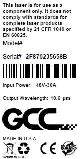
6 Label Locations
7 Laser Safety To prevent exposure to direct or scattered laser radiation, follow all safety precautions specified throughout this manual and exercise safe operating practices per ANSI Z at all times when actively lasing. Always wear approved Laser Safety Glasses with a minimum OD (Optical Density) 4.27 for a wavelength of 10.6 µm or the specific wavelength of your laser. A CO2 laser is capable of igniting most materials under the proper conditions. Never operate the laser in the presence of flammable or explosive materials, gases, liquids, or vapors. Other Hazards The following hazards are typical for this product family when incorporated for intended use: (A) risk of injury when lifting or moving the unit; (B) risk of exposure to hazardous laser energy through unauthorized removal of access panels, doors, or protective barriers; (C) risk of exposure to hazardous laser energy and injury due to failure of personnel to use proper eye protection and/or failure to adhere to applicable laser safety procedures; (D) risk of exposure to hazardous or lethal voltages through unauthorized removal of covers, doors, or access panels; (E) risk of exposure and/or interference from radio-frequency (RF) electro-magnetic energy through unauthorized removal of covers, doors, or access panels; (F) generation of hazardous air contaminants that may be noxious, toxic, or even fatal

8 **NOTICE** Iradion Lasers are shipped with a protective tape covering over the laser s aperture. THIS MUST BE REMOVED BEFORE USE. If not, when the laser is fired, smoke and debris can damage the laser s output window. THIS WILL VOID THE WARRANTY
9 Declaration of Conformity In accordance with ISO / IEC :2004 We, Manufacturers Name: Iradion Laser, Inc. Manufacturers Address: One Technology Drive Uxbridge, MA USA Hereby declare under our sole responsibility that the following equipment: Product Name: Model Number: Infinity 15XXSB Conforms to the following Directive(s) and Standard(s): Applicable Standard(s): IEC , 3 rd Ed., 2014 EN 55011:2009/A1:2010 EN :2007 Safety of Laser Products Group 2 Class A ISM emissions requirements (EU) Emissions requirements for heavy industrial environments - Generic EN :2005 Immunity for heavy industrial environments - Generic Serial Number Range: Starting at serial number 2190 (Decimal) Corporate Officer:
10 Declaration of Conformity The European Union has established requirements for Restriction of Hazardous Substances (RoHS) in all Electrical and Electronic Equipment (EEE). Please see Directive 2011/65/EU which entered into force 21 July, 2011 and becoming effective 2 January, We, Manufacturers Name: Manufacturers Address: Iradion Laser, Inc. One Technology Drive Uxbridge, MA USA certify that to its knowledge that the products listed below conform to the requirements of the European Union s Restriction on Use of Hazardous Substances in EEE RoHS II Directive, 2011/65/EU which may or may not include exemption in the directive. Product Name: Model Number: Infinity 15XXSB To comply with RoHS II, all CE marked products require a Declaration of Conformity (DoC) and that a technical file be made available upon request. For finished EEE where Iradion Laser, Inc. is the legal manufacturer, Iradion will provide the CoC and the technical documentation. Iradion will make available part-specific Certificates of Compliance demonstrating compliance to the banned substances of RoHS II. The six substances affected are: Lead (Pb) Hexavalent Chromium (Cr +6) Mercury (Hg) Polybrominated Biphenyl (PBB) Cadmium (Cd) Polybrominated Diphenyl Ether (PBDE) Based on our own internal analyses, vendor supplied analyses, and/or material certifications of the raw materials used in the manufacture of Iradion Laser, Inc. We declare the products listed above, starting at serial number 8000 (decimal), comply with and conform to RoHS regulations. Corporate Officer:
11 Introduction This guide provides the basic information needed to operate an Iradion Laser. This laser is designed for use while integrated within a system and is not designed to meet CDRH requirements as a stand-alone product. As such, the user must be aware of certain requirements before use. CDRH This is an OEM laser component that has been designed for integration into a functioning laser system. As a stand-alone device, it cannot be turned on and therefore does not incorporate all of the safety features required by the Center for Devices and Radiological Health (CDRH). Provisions for the incorporation of these safety features are available, and it is expected that the user will apply them and fully comply with all CDRH requirements. Available Safety Features The following safety features are available as electronic signals on the rear panel interface: Interlock Key switch Power up in Fault Lase signal Fault signal Indicator lights Upon contact closure, allows the system to operate. An open connection will prohibit the laser from firing. Upon contact closure, allows the laser to fire after imposing a 5-second delay. (Key switch function is program version dependent.) Requires the key switch to be cycled. (Program version dependent.) Output signal indicating the laser is firing. Output signal indicating the malfunction of an internal component or the electronics. DC Power, Temp Warning, Interlock, Fault, Ready, Lase
12 System Overview Iradion CO2 lasers are rated from 40 to 120 Watts. They can be overpowered to up to 180 Watts, and they all integrate radio frequency power amplifier and cooling in one package. Two connectors in the rear provide the interface to control signals, power, and returns diagnostic signals and faults signals. Connector pins and associated electronics are protected against static ESD damage. DC power is applied to the one meter power cord. Caution There are no user-serviceable parts under the cover. The RF cover must be removed according to procedure; otherwise, damage could occur. The RF cover edges are RF sealed to the top heat sink, which makes it very difficult to slide off the cover. The laser may not operate properly without the cover in place. There are dangerous RF voltages under the cover that will cause serious RF burns to the skin if touched. Caution The lasers are waveguide lasers with a slab unstable optical resonator. The resulting elliptical beam is corrected by a cylindrical lens in the faceplate. This assembly is exactly positioned so that the beam direction is close to the original elliptical beam. Removal of the cylindrical lens assembly will result in the loss of this original alignment and will require a procedure for replacement. Caution The optical intensity at the cylindrical lens is VERY high (>6000 W/cm 2 ). Any contamination to the optical surface could cause runaway destruction of the lens. Do NOT burn materials close to the lens or leave fingerprints on the lens. Caution The cylindrical lens comes with a pink plastic cap that covers the lens for protection. Remove this cap before applying DC power. Firing the laser through the cap WILL cause permanent damage to the lens
13 Quick Start Connection Guide There are two connectors on the rear of the laser available for operation of the laser. The 15 pin D connector contains all the available connections for operation. The RJ-45 connector contains a basic set of connections. Power Cable, All Lasers Designation Pin Description Comment Black - Power Ground 10 AWG wire to power supply Ground Red - Power VDC positive connection Connector (RJ-45), All Lasers Designation Pin Description Comment 10 AWG wire to power supply RJ-45 1 Modulation High in TTL relative to GND or Pin 6. RJ-45 2 Fault LED drive pin Grounded Cathode. RJ-45 3 Interlock Grounded Interlock will enable laser. RJ-45 4 CTL TXD RS232 transmit line. RJ-45 5 CTL RXD RS232 receive line. RJ-45 6 Modulation low in RJ-45 7 Ground System GND. RJ-45 8 Ground System GND. This line grounded or driven independently for command line isolation
14 Connector (HD-15) NOTE: The use of standard video cables with a HD-15 pin connector is not permitted when interfacing to this connector. Designation Pin Description Comment HD-15 Pin 1 CTL TXD RS 232 transmit. HD-15 Pin 2 CTL RXD RS 232 receive. HD-15 Pin 3 Modulation Low In This line grounded or driven independently for command line isolation. HD-15 Pin 4 Modulation High In* TTL signal relative to pin 3. HD-15 Pin 5 Ready LED Drive HD-15 Pin 6 Key Switch in HD-15 Pin 7 Fault LED drive pin Signal to drive an LED directly with grounded cathode. 33mA, 150Ω series resistor. Ground this line through key switch to arm laser. Signal to drive an LED directly with grounded cathode. 33mA, 150Ω series resistor. HD-15 Pin 8 Forward Monitor Out 1 Signal use optional. HD-15 Pin 9 Reflected Monitor Out 1 Signal use optional. HD-15 Pin 10 Forward Monitor Out 2 Not Used. HD-15 Pin 11 Lase LED drive pin HD-15 Pin 12 Reflected Monitor Out 2 Not Used. HD-15 Pin 13 Interlock signal Signal to drive an LED directly with grounded cathode. 33mA, 150Ω series resistor. HD-15 Pin 14 Ground System Ground. HD-15 Pin 15 Temperature Warning LED drive pin *The laser may be modulated at up to 140 khz. Ground this line through switch to enable laser. Signal to drive an LED directly with grounded cathode. 33mA, 150Ω series resistor
15 Caution This unit is provided with a one meter length of cable for DC power. If the wire is extended in length, #10 wire must be used. Do not add more than 1 meter additional wire unless it is heavier than #10. Power supply regulation should be greater than ±2% and ripple no greater than 400 mv. No damage can occur to the laser if the DC voltage is in the range of 0 to 50 Volts; however, the laser will only operate at the specified voltage. Check your power supply before attachment and adjust it to the specified voltage. The software will not allow more than ± 2 Volts variation including line drops at high current settings. If output becomes intermittent and the fault light flashes on and off, the voltage drop on the power cable may be too large or the power supply may be bad. If the fault light lights up on power up, check the power supply voltage setting. Nominal Operating Voltages Infinity 15XXSB Models DC Voltage: µm µm F Type Lasers Fan Cooled lasers are designed to control fan operation internally based on the operating temperature. The fan will start operating at 32 C or higher and will stop at 30 C or lower. This fan function is enabled via commands sent over the RS 232 lines. If the fans do not start when power is applied, this means that the fan function is disabled. If fans do not start with power up, this does not indicate fan malfunction! Factory fresh lasers are always shipped with the fan function disabled. See the Iradion LCC Comm Protocol_v1.5 for information on communicating with the laser control card. W Type Lasers Water cooled lasers require water connections before operation. See Other Connection Details below. Water cooled lasers cannot detect water flow. If the laser is operated without water flow, a fault will occur due to overheating after several minutes (depending on the operating duty). Damage will not occur
16 Operation of Unit 1. Mount the laser in a manner such that the beam will strike a target capable of absorbing at least 180 Watts of power. Make sure that the airflow openings are clear of any obstructions. 2. Confirm that the signal connections to the laser are secure and tight. Make sure that the power supply is correctly adjusted and is capable of delivering a minimum of the rated amps plus 2 amps margin. 3. Connect the laser power leads to DC, Red + using at least 10-gauge wire. The power supply can affect laser performance! Use a high-quality, well-regulated supply. 4. Power up the DC supply. The fans should start. (The F fan option, when programed, will not start the fans until the laser reaches a preset temperature.) 5. Make sure the "INTERLOCK" switch is down or off, or the interlock line is ungrounded. 6. The Key Switch line must be toggled from off to on to arm the laser. If the switch is closed when power is applied, turn it off and then on. There will be a 6 second delay before the green "READY" light lights up. (This switch must be toggled to arm the system after power up.) NOTE: This function depends on the software version and programming. OEM lasers are shipped without this function. 7. When the system arms to "READY", if the tickle is being applied, the "LASE" light should also light up when the interlock is enabled. The "LASE" light will get brighter as the power increases; this is normal. 8. The Mod Hi connection to the laser requires that the command signal contain a tickle pulse of 1 to 3 s at 5,000 Hz when the laser is not being commanded to fire. Tickle rates of greater than 5,000 Hz will result in dangerous conditions (possible unexpected low level emissions). When the laser is being commanded, the modulation rate can reach up to 140 khz. NOTE: OEM lasers may be shipped with the tickle function disabled. In this case, the user must provide the correct tickle protocol at all times. 9. Make sure there is enough cool air available to dump the heat! Do not obstruct the air flow in any way or modify the fans. The laser should not be near heaters or other heat sources that increase the ambient fan inlet temperature
17 Tickle Pulse Iradion has chosen to follow the industry convention and make provision for the inclusion of a tickle pulse function to keep the laser lit during down time. The intent of the tickle pulse is to improve the pulse-to-pulse consistency and timing relative to firing commands received from the control electronics. This function may be disabled if required by the customer. If disabled, there is no signal processing done to incoming commands to fire. Adjustments to the signal processing can be made via the RS232 interface covered in the Iradion LCC Comm Protocol_v1.5 document. The laser command line (modulation high) requires a 1 to 3 s pulse repeated at 200 s intervals when there is no output commanded. There is an adjustable pulse stretcher within the laser control board that is set to just below the threshold of the laser producing light, assuming the implied 5000 Hz tickle rate. Warning If the tickle rate increases due to software settings or deliberate measures, there is a danger of unintended laser emission. NOTE: If the user desires to control the sub-threshold tickle within the external host control software, Iradion can set the tickle stretch to 0 s upon request before shipping. This would be required if, for example, the software required a tickle rate greater than 5000 Hz
18 Laser Command Signals During laser bench testing, it is recommended that command signals be generated from an Iradion Laser Controller or properly programmed pulse generator. These units can provide the tickle pulse and drive signals needed to test and operate the laser properly. Alternatively, most motion control software packages are designed to provide the proper pulse protocol. The Modulation pins on both the D connector, pins 3 (low) and 4 (high) and the RJ-45, pins 1 (high) and 6 (low) are designed to allow either floating or grounded input modes. Both the High and Low pins should be used in either case. A software setting made through the RS232 interface will either ground Modulation Low or leave it floating. Factory setting is set to ground Modulation Low. It is possible to use the Modulation High pin only if the Modulation Low pin is grounded by software settings or by a physical wire; however, depending on the ground integrity of the host system and level of ground noise this may not be the best solution. The diagram below shows the circuit of the modulation input interface:

19 System Test The operation of the laser is possible after the above connections are completed. To test the laser, apply power and the tickle command signal. If the software settings require a key switch, toggle it off and on. After about 6 seconds, the system will be armed. The interlock connections must be closed to operate the system. Fault conditions can be detected by viewing the LED indicators on the rear of the laser. The signals monitored with LEDs are: LASER READY Lights up when the laser controller is ready for operation. OVERTEMP FAULT LASE LED POWER INTERLOCK Lights up when the RFPA is getting too hot. Faults at Temp limit. Lights up when the controller is in a Fault state. Lights up whenever signals are delivered to the RFPA FET bias. Lights up whenever DC power is applied. Lights up when the interlock switch is closed. Laser Indicator Lights Cooling Temp Lights Faults Air 55 C 60 C Water 35 C 40 C
20 Water Cooled Laser Connections The W lasers require water cooling connections. The rear plate of these lasers is pictured below: Cooling Specifications: Flow Rate liters/minute Water Temp Non-Condensing, 18 C to 24 C Inlet Pressure 413kPa Hardness <250mg/liter Heat Load >1.5kW ph 6 to 8 Particulate Size <200 microns NOTE: No condensing allowed. See Dew Point Chart below. Connections to IN and OUT require polyethylene tubing of ½ inch outside diameter that is capable of handling pressure of up to 60 psi (4 bar). The internal cooling components of the laser are rated at 60 psi
21 The following materials are used in the cooling path of the laser: Delrin Copper Viton rubber The recommended coolant is distilled water. Additives should be used to control corrosion and algae as recommended by the manufacturer of the chiller. Use high quality water such as distilled or deionized water to avoid scale buildup. Keep the concentration of water at above 90% relative to additives to maximize the specific heat of the coolant. Caution Maintain the coolant ph above 7 to avoid damage to the copper cooling pipes. Never use tap water for cooling. The mineral content, temperature, or ph may cause damage. Never allow condensation to form on the laser. If condensation forms, DO NOT operate the laser until it is dry again. If any water leaks are detected at the laser, SHUT DOWN IMMEDIATLY!

22 Condensation In some environments, where the temperature and humidity are high, the temperature setting of the cooler may need to be set higher than the specifications indicate. The chart below shows the dew point at various air temperatures and relative humidity. To determine the dew point temperature, measure the air temperature and relative humidity. Draw a horizontal line from the air temperature (Y-axis) to the relative humidity line. Then draw a vertical line from that intersection down to the dew point temperature (X-axis)
23 Iradion RS232 Com Test Software The Iradion Infinity Series Lasers allow user communication to the control card through a utility software package. This package is documented in LCC com protocol (Customer Ver). Certain production functions are omitted in the customer version because irreversible changes could be made that would render the laser inoperable. The software functions on Windows XP, Vista and System 7 operating systems. A properly configured com port must be available and the com port number must be known before launching the software. The available functions are: Get Status Get Options Get Laser Serial Number Set Auto Fan Enable (if this hardware option is available) Set Auto Fan Disable (if this hardware option is available) Set Mod Low Grounded Set Mod Low Not Grounded Set Keylock Switch Disable (not available in current software) Set Keylock Switch Enable (not available in current software) Set Simmer Frequency (5 khz to 200 khz) Set Simmer Duty Cycle (0% to 20%) (factory default is 0%) Set Pulse Stretch (0 µs to 10 µs) (factory default is 0 µs) If the laser control card is reprogramed to a newer version, all of the optional settings must be manually reset using the Com Test Software, and the correct serial number must also be installed. A special procedure is required to restore these settings, which is not covered in this manual
24 Mechanical Outline Fan cooled 1 Meter Power Cord Water cooled 1 Meter Power Cord
25 Specifications, 10.2 µm and 10.6 µm Infinity Models 15XXSB Rated Optical Power (Watts) Mode Quality (M²) Beam Ellipticity <1.2:1 <1.2:1 <1.2:1 <1.2:1 <1.2:1 Beam Diameter (mm)1/e² Beam Divergence (mrad, full angle) Wavelength (μm) 10.2, , , , , 10.6 Rise Time (μs) <75 <75 <75 <75 <75 Pulse Duration (μs) Duty Cycle 0-100% 0-100% 0-100% 0-100% 0-100% Power Stability, Fan Cooled, from cold start Power Stability, Water Cooled, from cold start <±6% <±6% <±6% <±6% <±6% <±3% <±3% <±3% <±3% <±3% Polarization Random Random Random Random Random Cooling Fan or Water Fan or Water Fan or Water Fan or Water Fan or Water Input Power (Watts) Input Voltage/Current 32V / 25A 40V / 25A 45V / 25A 48V / 30A 50V / 28A Weight (kg / lbs) 14.7 / / / / /
26 Specifications, 9.3 µm Infinity Models 15XXSB µm µm Rated Optical Power (Watts) Mode Quality (M²) Beam Ellipticity <1.2:1 <1.2:1 Beam Diameter (mm)1/e² Beam Divergence (mr, full angle) Wavelength (μm) Rise Time (μs) <75 <75 Pulse Duration (μs) Duty Cycle 0-100% 0-100% Power Stability, Fan Cooled, from cold start Power Stability, Water Cooled, from cold start <±7% <±7% <±5% <±5% Polarization Random Random Cooling Fan or Water Fan or Water Input power (Watts) Input Voltage/Current 45V / 25A 50V / 30A Weight (kg / lbs) 14.7 / /


27 Troubleshooting Problem The unit is in the Ready mode but will not respond to commands. The Over Temp Light lights. Laser power seems low. Fault light is lit. Solution The Interlock Switch is open. Mod LOW is not properly grounded. The RFPA heat sink is too hot for operation. Above 60 C, a Fault will also occur. Improve cooling. Check for intake blockage. Operating temperature is very high. The fan(s) have failed. The heatsink is clogged with dust. Optical damage to lens. RFPA malfunction. The laser is too hot. The DC voltage is outside the proper range. Patents: US B2 US B2 Invisible Laser Radiation Avoid eye Skin exposure to direct or scattered radiation. Class 4 Laser Product. Iradion Laser Inc., One Technology Drive Uxbridge, MA Tel: Fax:
SYNRAD Laser Safety 101
 SYNRAD Laser Safety 101 Version 2.1 Released June 2018 SYNRAD is a registered trademark of Novanta Corporation. Novanta Corporation 2018. All Rights Reserved. No reproduction without written authorization.
Important Safety Notice
 Date: 27 th April 2015 Page 1 of 12 SPI Lasers UK Limited Safety Information High Power OEM Fibre Lasers Important Safety Notice This notice outlines important safety related information and must be read
9 W, 15 W and 25 W Industrial Fiber Laser Systems IFL Series
 COMMERCIAL LASERS 9 W, 15 W and 25 W Industrial Fiber Laser Systems IFL Series Key Features Diffraction-limited light delivered through fiber termination module Single transverse mode, collimated beam
G4 Pulsed Fiber Laser
 G4 Pulsed Fiber Laser OEM Safety and System Integration Manual Module types C1 and C2 Module type C1 - fitted with IBeam1 delivery optic Module type C2 - fitted with IBeam2 delivery optic 1 1 Preface Definition
3kW 6kW, QUBE Fiber Lasers
 3kW 6kW, QUBE Fiber Lasers CONTENTS 1.1 SCOPE 2 1.2 OPTICAL SPECIFICATION 2 1.3 BEAM DELIVERY FIBER SPECIFICATION 3 1.4 SHARE UNITS 3 1.5 ALIGNMENT LASER 3 1.6 POWER DISTRIBUTION 4 1.7 WATER COOLING REQUIREMENTS
High-Power Q-Switched Diode-Pumped UV Laser Q-Series, Q305
 High-Power Q-Switched Diode-Pumped UV Laser Q-Series, Q305 The new high-power Q305 laser is an expansion of the existing Q-Series that provides a solution for demanding applications requiring faster throughput.
2 Ensure that all personnel in the area are wearing the appropriate protective eyewear.
 SYNRAD, Inc. 4600 Campus Place Mukilteo, WA 98275 tel 1.425.349.3500 fax 1.425.349.3667 e-mail synrad@synrad.com web www.synrad.com Power Wizard PW-250 Operating Instructions Important Power Wizard power
North Dakota State University Laser Safety
 North Dakota State University Laser Safety I. Introduction The laser represents a class of light emitting devices with unique characteristics. Some of these characteristics can result in significant hazards.
DUQUESNE UNIVERSITY. Laser Safety Program
 DUQUESNE UNIVERSITY Laser Safety Program Prepared by: Environmental Health and Safety Department TABLE OF CONTENTS Page Purpose 1 Scope 1 Introduction 1 Registration of Laser Systems 2 Laser Safety Training
FIRERAY 5000 range USER GUIDE
 FIRERAY 5000 range USER GUIDE 0044-003-04 IMPORTANT PLEASE NOTE: The beam path MUST be kept clear of obstructions at all times! Failure to comply may result in the Detector initiating a Fire or Fault signal.
T3/E3 Fiber Optic Line Drivers
 MT618A-ST-R3 January 2004 MT619A-ST-R2 MT620AE-R2 T3/E3 Fiber Optic Line Drivers CUSTOMER SUPPORT INFORMATION Order toll-free in the U.S.: Call 877-877-BBOX (outside U.S. call 724-746-5500) FREE technical
G4 Pulsed Fiber Laser
 G4 Pulsed Fiber Laser OEM Safety and System Integration Manual Module types B1 and B4 Module type B1 - fitted with ILLK beam delivery optic Module type B4 - fitted with ILOC beam delivery optic 1 1 Preface
EVC-P CONVENTIONAL PHOTOELECTRIC SMOKE DETECTOR. instruction manual. evolution EVC-P Conventional Photoelectric Smoke Detector
 EVC-P CONVENTIONAL PHOTOELECTRIC SMOKE DETECTOR instruction manual Ref No: NISM/EVC-P/03 Date: Jan 2010 Issue: 3 Quality System Certificate No. 041 Assessed to BS EN ISO 9001:2000 NITTAN (UK) LTD. Hipley
Laser Safety and Regulations Division of Physics and Applied Physics, School of Physical and Mathematical Sciences Nanyang Technological University
 , INTRODUCTION The requirements in this manual apply to lasers in classes 3b and 4 only. The hazards from lasers in classes 1, 2 and 3a are less significant than the higher-powered lasers in classes 3b
SECTION 1: STARTING 1.1 UNPACKING AND INSPECTION
 SECTION 1: STARTING 1.1 UNPACKING AND INSPECTION Upon receipt of the laser system, inspect the shipping containers for gross external damage. Unpack the unit and inspect for internal damage. If any damage
Stony Brook University Hospital Environmental Health & Safety Policy & Procedure Manual. EH&S 6-8 Original : 1/00 Revision Date: 3/16/15 Pages 6
 Title: Laser Safety Stony Brook University Hospital Environmental Health & Safety Policy & Procedure Manual EH&S 6-8 Original : 1/00 Revision Date: 3/16/15 Pages 6 PURPOSE: SCOPE: To protect University
Title: Laser Safety Effective Date: 9/91 Revision: 2/97 Number of Pages: 7
 Environmental Health and Safety Manual Policy Number: EH&S 6-8 Title: Laser Safety Effective Date: 9/91 Revision: 2/97 Number of Pages: 7 PURPOSE: SCOPE: To protect University employees against health
FSS-Series Heavy-Duty Flat panel Emitter Electric Overhead Infrared Heaters
 TPI Corporation P.O. Box 4973 Johnson City, TN 37602 www.tpicorp.com FSS-Series Heavy-Duty Flat panel Emitter Electric Overhead Infrared Heaters FSS-14 FSS-43 FSS-31 FSS-95 IMPORTANT SAFETY INFORMATION
LASER SAFETY BARRIER
 LASER SAFETY BARRIER 5' x 6' Portable Laser Barrier No-Trip Base Design High CW and Pulsed Damage Thresholds SB5X6 All Contents Stored In Base OVERVIEW Features Portable 5' x 6' (1.5 m x 1.8 m) Barrier
NLC C61 Air-Cooled Argon-ion Laser
 NLC C61 Air-Cooled Argon-ion Laser User s Manual Complete with Operating Instructions for the 9470 and 2270 Power Supply TABLE OF CONTENTS CHAPTER 1: INTRODUCTION 1 CHAPTER 2: LASER SAFETY 2 CENTER FOR
Erbium-Doped Fiber Amplifier (EDFA) - MW Series
 - MW Series") Nanovation s MW series of EDFA products is designed for applications in advanced dense wave division multiplexing (DWDM) systems where high performance and reliability are critical. They are available
Nanovation s MW series of EDFA products is designed for applications in advanced dense wave division multiplexing (DWDM) systems where high performance and reliability are critical. They are available
Operating Instructions
 Operating Instructions ProVicom MT-65, MT-125 R. STAHL HMI Systems GMBH Im Gewerbegebiet Pesch 14 50767 Köln Version 1.7 Issue: 21.07.2008 R. STAHL HMI Systems GmbH / OperatingInstruction_Provicom_Falcon_en_1_7.doc
OWNERS MANUAL OPERATION GUIDE
 OWNERS MANUAL OPERATION GUIDE Built in Redmond Oregon USA www.laserlinemfg.com P/N 1700-0041 REV. 7.24.17 PRODUCT OVERVIEW The GL1700 Laser Guide was designed from the ground up to provide precise start-stop
Information for Proper Posting & Laser Area Sign Templates
 Information for Proper Posting & Laser Area Sign Templates All signs must be conspicuously displayed at locations where they best serve to inform all. Any area that contains a Class 3R, Class 3B and Class
ELLA ID. High CRI, High lm/w OptoDrive LED-module
 ELLA ID ELLA ID High CRI, High lm/w OptoDrive LED-module Page 2 of 24 Pages for reference: Pages for reference:... 2 Introduction... 3 Short form Characteristics... 4 Wiring diagram:... 6 Accessories to
OTEB-CO-B EDFA WITHOUT SNMP INSTRUCTION MANUAL
 OTEB-CO-B EDFA WITHOUT SNMP INSTRUCTION MANUAL Phone: (209) 586-022 (800) 545-022 Fax: (209) 586-026 E-Mail: salessupport@olsontech.com www.olsontech.com OTEB-CO-B (No SNMP) Rev. X7 /7/200 SAFETY WARNINGS
IMPORTANT. PLEASE NOTE: The infrared beam path MUST be kept clear of obstructions at all times!
 USER GUIDE English IMPORTANT PLEASE NOTE: The infrared beam path MUST be kept clear of obstructions at all times! Failure to comply may result in the Detector initiating a Fire or Fault signal. Contents
FSA-Series Heavy-Duty Flat panel Emitter Architectural Electric Overhead Infrared Heaters
 TPI Corporation P.O. Box 4973 Johnson City, TN 37602 www.tpicorp.com FSA-Series Heavy-Duty Flat panel Emitter Architectural Electric Overhead Infrared Heaters FSA-14 FSA-43 FSA-31 FSA-95 IMPORTANT SAFETY
Automatic Water System Pump SERIES
 Automatic Water System Pump 42755 SERIES Automatic Water System Pump Purpose of this manual The purpose of this manual is to provide necessary information for product installation, operation and maintenance.
Freightliner Refrigerator Troubleshooting Guide For (TJ18F) (TJ22F) (TJ18FP3)
 (TJ22F) (TJ18FP3)") www.dometic.com Freightliner Refrigerator Troubleshooting Guide For Before initiating troubleshooting, the following equipment is recommended: Multimeter, 20 gauge (min) wires to use as jumpers, and 12Vdc
www.dometic.com Freightliner Refrigerator Troubleshooting Guide For Before initiating troubleshooting, the following equipment is recommended: Multimeter, 20 gauge (min) wires to use as jumpers, and 12Vdc
Solo PIV Nd:YAG Laser System Operator s Manual
 Solo PIV Nd:YAG Laser System Operator s Manual January 2005 Part No. 90-1020E Solo PIV Operator s Manual Preface This manual contains information for proper installation and operation of the Solo PIV and
LaserGuard2. Laser Collision Avoidance System. Part Number: R1 April 2015 Copyright 2015 Magnetek Material Handling
 LaserGuard2 Laser Collision Avoidance System Part Number: 147-20004 R1 Copyright 2015 Magnetek Material Handling Table of Contents Service Contact Information... 3 1. Preface and Safety... 4 1.1. Product
LASER SAFETY. Class 2 and 2a - low power, low risk Class 2 and 2a lasers have low power and emit visible light. They will cause harm if viewed
 LASER SAFETY Laser is an acronym for light amplification by stimulated emission of radiation. Radiation in this case occurs in the portions of the electromagnetic field with insufficient energy to induce
This is to certify that the optical output of the: SENSORNET LR-DTS Temperature Sensing System: (Variants Mark 1, Mark 2a and Mark 2b)
") Optical Services Ltd. This is to certify that the optical output of the: SENSORNET LR-DTS Temperature Sensing System: (Variants Mark 1, Mark 2a and Mark 2b) Meets the requirements stated in IEC 60825-1:2001
Optical Services Ltd. This is to certify that the optical output of the: SENSORNET LR-DTS Temperature Sensing System: (Variants Mark 1, Mark 2a and Mark 2b) Meets the requirements stated in IEC 60825-1:2001
Datasheet: K-22 LO Sensor
 Datasheet: K-22 LO Sensor The K- 22 LO is a CO2 sensor module designed to be built- in into stationary ventilation equipment, such as window vent or duct exhaust actuators, serving as a linear transmitter
Laser Use Authorization
 Part I Laser Registration NOTE: All lasers of Class 3B and Class 4 must be registered with the Environmental Health and Safety Office and Radiation Safety Committee (RSC). Please complete this form for
Fiber Tower Desktop SAFETY & OPERATION MANUAL
 Fiber Tower Desktop SAFETY & OPERATION MANUAL 400 Rinehart Rd.; Suite 1000 Lake Mary, FL 32746 TEL.: (407) 477-5618 FAX: (407) 804-1002 www.laserphotonics.com Copyright by Laser Photonics, 2015 All Rights
Hazard Analysis, Mitigation, and Operating Procedures for (Laser name) Laser
 Laser") Hazard Analysis, Mitigation, and Operating Procedures for (Laser name) Laser Prepared by: Date: Rev. 6/24/2016 Page 1 of 6 Table of contents Summary of identified hazards and hazards mitigation: 1. General
Hazard Analysis, Mitigation, and Operating Procedures for (Laser name) Laser Prepared by: Date: Rev. 6/24/2016 Page 1 of 6 Table of contents Summary of identified hazards and hazards mitigation: 1. General
Installation and Operation Manual
 [Please read this installation & operation manual before install and use this Installation and Operation Manual Address: 8-701,Dongfangming Industry Zone, Dabao Road., Baoan, Shenzhen, China-518101 Page
Modular LIBS System. User s Manual. May 2015 Doc. Ref.: UM/ /02
 Modular LIBS System User s Manual May 2015 Doc. Ref.: UM/0168-01/02 Applied Photonics Ltd Unit 8 Carleton Business Park, Skipton, North Yorkshire BD23 2DE, United Kingdom Tel +44 (0) 1756 708900 Fax +44
NIR O P E R A T I N G I N S T R U C T I O N S RETROREFLECTIVE PHOTOEYE U L M O N I T O R E D DEVICE
 O P E R A T I N G I N S T R U C T I O N S NIR-50-325 RETROREFLECTIVE PHOTOEYE U L 3 2 5-2 0 1 8 M O N I T O R E D DEVICE 4564 Johnston Parkway, Cleveland, Ohio 44128 P. 800 426 9912 F. 216 518 9884 Sales
Sintrol Snifter A2 EX. Manual. Version 1.2.3
 Sintrol Snifter A2 EX Manual Version 1.2.3 Table of Contents 1 INTRODUCTION... 3 1.1 Safety... 3 1.2 Product overview... 4 1.3 How does it work?... 4 2 INSTALLATION... 4 2.1 Selecting the installation
APC BC300 Series 40kW 208/450/480V User Guide
 APC BC300 Series 40kW 208/450/480V User Guide Copyright 2002 APC Denmark ApS This manual is subject to change without notice and does not represent a commitment on the part of the vendor Thank You Thank
ACCURATE ELECTRONICS INC PO BOX SW HALL BLVD BEAVERTON OR USA FAX
 Page 1 of 10 Model 10807800 January 2014 ACCURATE ELECTRONICS INC PO BOX 1654 97075-1654 8687 SW HALL BLVD 97008 BEAVERTON OR USA 503.641.0118 FAX 503.646.3903 WWW.ACCURATE.ORG Practice Section 10807800
385 SERIES REMOTE HANDHELD SIREN ETSA385HR
 ! WARNING Sirens produce loud sounds that may damage hearing: - Roll up windows. - Wear hearing protection. - Use only for emergency response. - Avoid exposure to siren sound outside of vehicle. Please
LZR -I30. max. detection range of 30 ft x 30 ft LASER SCANNERS FOR INDUSTRIAL DOORS LZR-I Page 1 of 12
 EN LZR -I30 LASER SCANNERS FOR INDUSTRIAL DOORS max. detection range of 30 ft x 30 ft 75.5667.07 LZR-I30 0509 Page of SAFETY The device contains IR and visible laser diodes. IR laser: wavelength 905nm;
PDU Power Distribution Unit for IP-NINJAR. User s Guide Ver
 Power Distribution Unit for IP-NINJAR PDU-1209 User s Guide Ver. 1.0.0 Thank you for choosing this IDK product. To ensure the best performance of this product, please read this User s Guide fully and carefully
NLC 210 Air-Cooled Argon-ion Laser
 NLC 210 Air-Cooled Argon-ion Laser User s Manual Complete with Operating Instructions for the 9470 and 2270 Power Supply TABLE OF CONTENTS CHAPTER 1: INTRODUCTION 1 CHAPTER 2: LASER SAFETY 2 CENTER FOR
Model 3300 Technical Support and Installation Manual
 Model 3300 Technical Support and Installation Manual Manual # T15011 Document Revision: A1 1. OVERVIEW 1 2. BASIC OPERATION 1 2.1 General 1 2.2 Field-of-View 2 2.3 Range 2 2.4 Environment 2 2.5 Configuration
Features. Figure 1. Recommended Application
 Features High energy density User programmable hold-up trip voltage Trip status indicator Designed for use with Calex DC/DC Converters Small package design (1.45 x 2.28 x 0.50 ) Excellent MTBF Aluminum
ML501P73 TYPE NAME. FEATURES High Output Power: 1.0W (Pulse) 0.5W (CW) High Efficiency: 1.0mW/mA (typ.) Visible Light: 638nm (typ.) 5.
 0.5W (CW) High Efficiency: 1.0mW/mA (typ.) Visible Light: 638nm (typ.) 5.") LASER DIODES TYPE NAME ML501P73 DESCRIPTION Mitsubishi ML501P73 is a high-power, highly efficient semiconductor laser diode which provides emission wavelength of 638 nm and standard light output of 1.0W
LASER DIODES TYPE NAME ML501P73 DESCRIPTION Mitsubishi ML501P73 is a high-power, highly efficient semiconductor laser diode which provides emission wavelength of 638 nm and standard light output of 1.0W
DEHUMIDIFIER. User Manual 50BT, 70BT
 User Manual DEHUMIDIFIER Model 50BT, 70BT Use & Care Guide Please read and follow all safety rules and instructions in this manual before operating. The product warranty is printed on the back of this
CDRH Requirements Guide
 Control Systemation Inc. 2419 Lake Orange Drive, Orlando, FL 32837 Phone: (407) 926-3500 Fax: (407) 926-3590 www.controlsystemation.com CDRH Requirements Guide 2 FALIT - CDRH Requirements Guide Introduction
LZR -I100/ -I110. LASER SCANNERS for industrial doors. User s Guide for product version 0600 and more
 EN LZR -I00/ -I0 LASER SCANNERS for industrial doors I00: max. detection range of 9.9 m x 9.9 m I0: max. detection range of 5.0 m x 5.0 m User s Guide for product version 0600 and more SAFETY The device
HOA1888 Series. Infrared Assemblies Wide Gap Transmissive Sensor. MICRO SWITCH Sensing and Control
 Wide Gap Transmissive Sensor HOA1888 Series FEATURES Choice of phototransistor or photodarlington output Visible ambient light and dust protective filter 12 mm (0.47 in.) slot width Snap-in housing The
MX1A and MX1B: Laser Displacement Detection Sensors. 85% to 110% of the rated voltage MX1A: 15VA, MX1B: 25VA
 MX1A and MX1B: Laser Displacement Detection MX1A and MX1B: Laser Displacement Detection Built-in math capabilities available (MX1B only) Digital display on amplifier; easy setting and monitoring (MX1B
INSTALLATION GUIDE. AXIS A1001 Network Door Controller
 INSTALLATION GUIDE AXIS A1001 Network Door Controller Liability Every care has been taken in the preparation of this document. Please inform your local Axis office of any inaccuracies or omissions. Axis
Inspection Detail. General Questions for Laser Labs
 Laser Lab Inspection Checklist Building/Room: Authorized User: Inspection #: Inspection Detail 1 This inspection is General Questions for Laser Labs 2 Laser Users List Verified by Laser Supervisor? 3 Laser
FOS 2000 / 1000 RGB 1
 FOS 2000 / 1000 RGB 1 PRODUCT SPECIFICATIONS TECHNICAL SPECIFICATION Voltage: 100/250 Volt AC, 50/60 Hz. Power Consumption: 50 Watt. Scanner: 25kpps High Speed optical scanner, +/- 30 scanning angle. LASER:
Laser Safety Part III Administration
 Laser Safety Part III Administration Environmental Health and Research Safety October 12, 2017 Part III Overview Regulatory Framework Laser Safety Program Control Measures Non-beam Hazard Precautions Emergency
Laser Safety Part III Administration
 Laser Safety Part III Administration Environmental Health and Research Safety October 24, 2016 Part III Overview Regulatory Framework Laser Safety Program Control Measures Non-beam Hazard Precautions Emergency
Square D Clipsal Outdoor Light-Level Sensor
 Square D Clipsal Outdoor Light-Level Sensor SLC5031PEWP for Use with C-Bus Wired Networks Instruction Bulletin Retain for future use. Square D Clipsal Outdoor Light-Level Sensor 63249-420-231A3 Instruction
TLS 600. Installation and Operation Manual. English Pages CEDES AG is certified according to ISO 9001: V 1.0.
 Installation and Operation Manual RoHS CEDES AG is certified according to ISO 9001: 2008 English Pages 2-12 111 189 130208 V 1.0 Contents 1. About this manual 2 1.1 Measurements 2 1.2 Related documents
CWDM-18. User manual. 18 channel CWDM mux/demux. Rev. B. Nevion Nordre Kullerød Sandefjord Norway Tel: nevion.
 18 channel CWDM mux/demux User manual Nevion Nordre Kullerød 1 3241 Sandefjord Norway Tel: +47 33 48 99 99 nevion.com Nevion Support Nevion Europe P.O. Box 1020 3204 Sandefjord, Norway Support phone 1:
A. Administrative. B. Labeling and Posting. C. Control Measures. Laser Safety Self-Audit Checklist. Building Room Principal Investigator Date
 Laser Safety Self-Audit Checklist Building Room Principal Investigator Date Audit Performed by A. Administrative 1. Lasers are classified appropriately (2, 3a, 3b, 4a, 4b) 2. Standard operating procedures
ML562G84 APPLICATION. Display system. Symbol Parameter Conditions Ratings Unit. Pulse (Duty 40%)
") TYPE NAME DESCRIPTION Mitsubishi is a high-power, highly efficient semiconductor laser diode which provides emission wavelength of 638 nm and standard light output of 2.5W (pulse). This LD has broad-stripe
TYPE NAME DESCRIPTION Mitsubishi is a high-power, highly efficient semiconductor laser diode which provides emission wavelength of 638 nm and standard light output of 2.5W (pulse). This LD has broad-stripe
Optical Smoke Detector Heat Detector Manual Call Point Output Unit Isolator
 TECHNICAL GUIDE Optical Smoke Detector Heat Detector Manual Call Point Output Unit Isolator The XPlorer Range XPlorer is a new range of analogue addressable detectors and interfaces developed for all who
SAFETY MANUAL. IR5000 Open Path Hydrocarbon Gas Monitoring System
 SAFETY MANUAL Open Path Hydrocarbon Gas Monitoring System The information and technical data disclosed in this document may be used and disseminated only for the purposes and to the extent specifically
TABLE OF CONTENTS. NOTE: Read the entire instruction manual before starting the installation. TROUBLESHOOTING... 13
 R 410A Duct Free Split System Air Conditioner and Heat Pump Product Family: DFS4(A/H) System, DFC4(A/H)3 Outdoor, DFF4(A/H)H Indoor NOTE: Read the entire instruction manual before starting the installation.
Original operating instructions Safety switch with guard locking AC901S AC902S
 Original operating instructions Safety switch with guard locking AC901S AC902S 7390914/03 01/2017 Contents 1 Preliminary note...4 1.1 Explanation of symbols...4 2 Safety instructions...4 3 Items supplied...5
ACCURATE ELECTRONICS INC
 ACCURATE ELECTRONICS INC Page 1 of 7 Model 108078 2 Sept 09 WWW.ACCURATE.ORG PO BOX 1654 97075-1654 8687 SW Hall Blvd 97008 BEAVERTON OR USA 503.641.0118 FAX 503.646.3903 Practice Section 108078 Rev A
CWDM-1-8 / 9-16 CWDM-1-8-M / 9-16-M CWDM-1-8-L / CWDM-9-16-L
 CWDM-1-8 / 9-16 CWDM-1-8-M / 9-16-M CWDM-1-8-L / CWDM-9-16-L 9-channel CWDM multiplexer and demultiplexer / multi mode (-M) / -low-loss (-L) User manual Nevion Nordre Kullerød 1 3241 Sandefjord Norway
Class 1 laser beam sensor safe for your eyes
 113 Sensor SERIES Related Information General terms and conditions... F-7 About laser beam... P.199~ Sensor selection guide... P.1~ General precautions... P.11 PHOTO PHOTO PARTICUR MEASURE ITY panasonic.net/id/pidsx/global
ML520G55 FEATURES. Package: φ5.6mm TO-CAN PKG APPLICATION. Reverse voltage
 TYPE NAME DESCRIPTION Mitsubishi ML5xx55 is a high-power, high-efficient semiconductor laser diode which provides emission wavelength of 638 nm and standard light output of 150mW. This LD has narrow-stripe
Wideband Optical Couplers
 Flashlink User Manual WOC-2-50-50 WOC-2-90-10 WOC-2-95-05 WOC-4-25 Wideband Optical Couplers network-electronics.com Rev. 3 Network Electronics ASA Thorøya P.O. Box 1020 N-3204 Sandefjord, Norway Phone:
Laser Use Registration & Application (L.U.R.)
") College of Science & Engineering San Francisco State University 1600 Holloway Avenue, TH323 San Francisco, California 94132-4163 (415) 338-6892 FAX (415) 338-6136 L.U.R. # COSE- Laser Use Registration
College of Science & Engineering San Francisco State University 1600 Holloway Avenue, TH323 San Francisco, California 94132-4163 (415) 338-6892 FAX (415) 338-6136 L.U.R. # COSE- Laser Use Registration
LZR -H110. LASER SCANNER FOR BARRIERS & GATES with max. detection range of 5.0 m x 6.5 m (16.5 ft x21 ft) User s Guide
 User s Guide") EN LZR -H110 LASER SCANNER FOR BARRIERS & GATES with max. detection range of 5.0 m x 6.5 m (16.5 ft x21 ft) User s Guide 75.5897.02 LZR-H110 20170821 Page 1 of 12 SAFETY The device contains IR and visible
EN LZR -H110 LASER SCANNER FOR BARRIERS & GATES with max. detection range of 5.0 m x 6.5 m (16.5 ft x21 ft) User s Guide 75.5897.02 LZR-H110 20170821 Page 1 of 12 SAFETY The device contains IR and visible
Guidance on the Restriction of the Use of Certain Hazardous Substances in Electrical and Electronic Equipment (RoHS) Regulations 2012
 Regulations 2012") Guidance on the Restriction of the Use of Certain Hazardous Substances in Electrical and Electronic Equipment (RoHS) Regulations 2012 Two Parts: 1. Products first placed on the market between 1 July 2006
Guidance on the Restriction of the Use of Certain Hazardous Substances in Electrical and Electronic Equipment (RoHS) Regulations 2012 Two Parts: 1. Products first placed on the market between 1 July 2006
TX7130. Conventional Reflective Beam Detector Installation and Operation Manual. TANDA UK Technology Copyright 2015, All right reserved.
 TX7130 Conventional Reflective Beam Detector Installation and Operation Manual Technology Copyright 2015, All right reserved. Product Safety To prevent severe injury and loss of life or property, read
RE-PR3-E-27 3-Phase Panel Mount 27kW
 Page 1 of 6 RE-PR3-E-27 3-Phase Panel Mount 27kW Features: Benefits: 0-10Vdc, 0-5Vdc, 4-20mA or manual via potentiometer control input Over temperature protection with auto reset Enclosed panel mounting
All personnel working in experimental areas at Jefferson Lab must have completed the EH&S Orientation at Jefferson Lab.
 1. Introduction Room 206A of the Free-electron laser Facility at Jefferson Lab (hereafter referred to as the Drive Laser Enclosure, or DLE) contains a Class IV laser 1 which drives the IR Demo injector
SAFETY MANUAL. Multispectrum IR Flame Detector X3301
 SAFETY MANUAL Multispectrum IR Flame Detector X3301 SAFETY-CERTIFIED MODEL X3301 MULTISPECTRUM INFRARED DETECTOR This manual addresses the specific requirements and recommendations applicable to the proper
CATALOGUE LASER POINTERS
 CATALOGUE LASER POINTERS SM.PROX SRL Via della Beverara 13/A - 40131 Bologna - Italy Tel. +39 051 6350755 - Fax +39 051 6353462 Edition October 2014 With the publication of this catalogue all former editions
All pulses < 4Hz (>0.25sec) BLUE>400mW. As measured under IEC measurement conditions for classification.
 BLUE>400mW. As measured under IEC measurement conditions for classification.") THUNDERBOLTB NON-INTERLOCKED HOUSING WARNING This unit contains high power laser devices internally. Do not open the laser housing, due to potential exposure to unsafe levels of laser radiation. The laser
THUNDERBOLTB NON-INTERLOCKED HOUSING WARNING This unit contains high power laser devices internally. Do not open the laser housing, due to potential exposure to unsafe levels of laser radiation. The laser
OCCUPATIONAL SAFETY AND ENVIRONMENTAL HEALTH GUIDELINE
 OCCUPATIONAL SAFETY AND ENVIRONMENTAL HEALTH GUIDELINE Subject: Laser Safety Date: 9/24/12 Revision: 04 Page: 1 of 16 SUMMARY: Laser use at the University of Michigan (U-M) encompasses many disciplines
INSTRUCTIONS. OJ-DV-Relay-Module. OJ Drives A DRIVES PROGRAMME DEDICATED TO VENTILATION SOLUTIONS. Optional module for OJ-DV motor controller
 INSTRUCTIONS OJ-DV-Relay-Module 67439B 10/16 (OSH) 016 OJ Electronics A/S Optional module for OJ-DV motor controller OJ Drives A DRIVES PROGRAMME DEDICATED TO VENTILATION SOLUTIONS Contents 1. Product
FUNCTIONAL SAFETY MANUAL. Gassonic Observer-H and Observer-i Ultrasonic Gas Leak Detector
 FUNCTIONAL SAFETY MANUAL Gassonic Observer-H and Observer-i Ultrasonic Gas Leak Detector The information and technical data disclosed in this document may be used and disseminated only for the purposes
Installation, Operating and Maintenance Manual
 STATUS ZONES CONTROLS FIRE FAULT DISABLED FIRE 1 2 3 4 5 6 7 8 TEST FAULT DISABLED 1 5 BUZZER SILENCE RESET 1 2 TEST 2 6 LAMP TEST 3 SUPPLY 3 7 SYSTEM FAULT 4 8 SOUNDERS ACTIVATE/ SILENCE 4 FAULTS INSTRUCTIONS
Class 1 laser beam sensor safe for your eyes
 1129 PHOTO PHOTO PARTICUR Sensor SERIES Related Information General terms and conditions... F-3 About laser beam... P.193~ guide... P.121~ General precautions... P.19 Conforming to FDA regulations (-11
Laser Safety Management
 Properties of Laser light Laser Safety Management Danny Fok Monochromatic (single wavelength) Directional (almost parallel low angular divergency) Coherent (in phase) Pulse or continuous Beam can be focused
Description. Features Standard OC-48 pin compatibility Narrow spectral linewidth Low noise Meets GR 468 reliability specifications
 Description The DFB-XXX-BF-10-EC-Fx-Hx-N126 laser modules are designed for fiber optic sensor applications. The narrow linewidth and the option of using polarization maintaining optical fiber made it specially
Laser Safety. This Laser Safety Program applies to the acquisition, use, transfer, and disposal of all Class 3B and 4 lasers at UNC Asheville.
 Laser Safety The UNC Asheville laser safety program requires that all lasers and laser systems be operated in accordance with the American National Standards Institute (ANSI) Z136.1 2007, American National
Diode-Pumped Solid-State Blue Lasers
 Diode-Pumped Solid-State Blue s 58 BLD Series 58 BSD Series Our diode-pumped solid-state blue lasers provide high power output in a compact air-cooled package. They are ideal for use in semiconductor,
C-Bus Four Channel Analogue Output Unit Installation Instructions
 C-Bus Four Channel Analogue Output Unit Installation Instructions 5504AMP Series REGISTERED PATENT Table of Contents Section... Page 1.0 Product Range...3 2.0 Description...3 3.0 Capabilities...3 4.0 Wiring
Class 1 laser beam sensor safe for your eyes
 13 Sensor SERIES Related Information General terms and conditions... F-17 About laser beam... P.13~ Sensor selection guide... P.967~ General precautions... P.1 PHOTO PHOTO Conforming to EMC Directive Conforming
SMART Dust Sensor. Amphenol Advanced Sensors SM-PWM-01C. Application Note. Features
 Application Note SMART Dust Sensor SM-PWM-01C SM-PWM-01C dust sensor detects dust particle concentration in air by using an optical sensing method. An infrared light emitting diode (IR LED) and a photo-sensor
380 SERIES REMOTE SIREN ETSA380R
 ! WARNING Sirens produce loud sounds that may damage hearing: - Roll up windows. - Wear hearing protection. - Use only for emergency response. - Avoid exposure to siren sound outside of vehicle. Please
NEED FOR LASER SAFETY
 NEED As our use of lasers increases, we have a tendency to think of them as commonplace, and we begin to forget that these small, often invisible light sources are able to cause permanent damage to our
XGUARD-10/-5. LASER SCANNERS for industrial doors. User s Guide for product version 0600 and more
 EN XGUARD-0/-5 LASER SCANNERS for industrial doors XGUARD-0: max. detection range of 9.9 m x 9.9 m XGUARD-5: max. detection range of 5.0 m x 5.0 m User s Guide for product version 0600 and more SAFETY
NIDS Dust sensor ED-N-DS-1408
 SPECIFICATION (Tentative) Product Name: Dust Sensor(High Sensitivity) Model No. : SM-PWM-01A-HS SMART dust sensor for air purifier SM-PWM-01A-HS Description SM-PWM-01A-HS is a dust sensor that detects