REFRIGERATOR SERVICE MANUAL CAUTION PLEASE READ CAREFULLY THE SAFETY PRECAUTIONS OF THIS MANUAL BEFORE CHECKING OR OPERATING THE REFRIGERATOR.
|
|
|
- Cori James
- 5 years ago
- Views:
Transcription
1 REFRIGERATOR SERVICE MANUAL CAUTION PLEASE READ CAREFULLY THE SAFETY PRECAUTIONS OF THIS MANUAL BEFORE CHECKING OR OPERATING THE REFRIGERATOR. MODELS: LSXC22386 * LSXC22326 * LSXC22336 *
2 CONTENTS SAFETY PRECAUTIONS PRODUCT STANDARD CIRCUIT DIAGRAM APPEARANCE SIZE OF REFRIGERATOR AND NAME OF EVERY PART MICOM FUNCTION ICEMAKER AND DISPENSER Working Principles COMPRESSOR TROUBLESHOOTING Freezer Sensor Error Refrigerator Sensor Error Temperature Sensor Error Icing Sensor Error Defrost Sensor Error Defrost Heater Error Freezer Fan Error Condenser Fan Error Communication Error Icemaker Motor Error TROUBLESHOOTING WITHOUT ERROR DISPLAY HOW TO DISASSEMBLE AND ASSEMBLE Handle Removal Dispenser Fan and Fan Motor Disassembly Method Icemaker How to adjust the refrigerator door level difference EXPLODED VIEW
3 Safety Warning and Cautions Chapter 1 Safety Warning and Cautions Observing cautions for safety can prevent accidents and dangers. Cautions are classified into Warning and Caution and the meanings are as follows WARNING WARNING indicates the possibility of serious injury or death if the instructions are not followed. CAUTION Caution indicates a hazardous situation with the possibility of product damage or personal injury if the instructions are not followed WARNING Be cautious of electric shock. Control board (PWB Main and Sub) uses power supply of about 120 VAC. Do not allow consumers to directly repair, disassemble, or modify the refrigerator. Harm, electric shock, or fire could occur. Be sure the plug and cord are not pressed by the rear side of the refrigerator. Damage to power plugs could result in fire or electric shock. Plug the refrigerator into a dedicated circuit. Plugging in too many appliances can result in fire or problems with the operation of your refrigerator. 3
4 Safety Warning and Cautions WARNING If grounding is required, be sure to consult an electrician. The refrigerator must be plugged in to a properly rated and grounded outlet. If you are not sure of your voltage or ground, consult a qualified and licensed electrician. Copper plate Grounding nut Grounding wire More than 75cm Do not store poisonous, flammable, or explosive chemicals in the refrigerator. There is danger of explosion and fire. Do not store medications or biohazardous products requiring precise temperature control. Do not use the refrigerator to store papers, electronic storage media, or similar items. The refrigerator is for storing food. This is a consumer household appliance and not a precision device. If storing or disposing of the refrigerator, remove the doors to eliminate the possibility of children playing in it. Children may become entrapped in the refrigerator. Unplug the refrigerator for cleaning or repair. Be sure your hands are dry when handling the power cord or plug. Firstly take power socket out for Electric shock may occur. Electric shock or harm may occur. Be sure the plug and socket are clean and the connection is tight. Dust or incomplete connection may result in fire. When dusts etc are stained to the pin part of the power socket, cleanly wipe out them. Fire may occur. 4
5 Safety Warning and Cautions WARNING Do not alter the power cord. Replace it only with an exact factory replacement part. Electric shock or fire may occur due to electrical damage of power cables. Do not place heavy objects on the refrigerator. Falling objects when opening or closing doors may cause injury. Do not hang or swing from the refrigerator doors. Do not allow children to play with the refrigerator. The refrigerator may turn over. Hands and fingers may be pinched. Do not use flammables near a refrigerator. There is danger of fire. Do not install the refrigerator next to a stove or other sources of heat. There is danger of fire. When a gas leak occurs, do not unplug the refrigerator. Open the doors for ventilation. There is danger of burning due to explosion and sparking. Do not clean the refrigerator by spraying water inside or outside. It may result in product damage, fire, or electric shock. This refrigerator is designed for use as a consumer home appliance only. It is not a precision device for storing medication or valuables. Do not install the refrigerator in a vehicle, aircraft, maritime vessel, or other than in a home environment. If the refrigerator is submerged or otherwise inundated with water, have it checked by an authorized servicer. Electric shock or fire may occur. 5
6 Safety Warning and Cautions WARNING Do put the vessel that flower base, cup, cosmetics or drugs, etc are contained on the refrigerator. Fire or electric shock may occur, or injury due to dropping may occur. Do not accumulate objects on a refrigerator or do not keep foods in random method. Dropping of objects when opening or closing the door may cause physical injury. Do not put glass bottles or other sealed containers in the freezer. They may burst, leaving glass fragments in the food and possibly causing injury. Be sure to use rated parts for replacement of electric parts. Use factory replacement parts. Secure the cord behind the refrigerator. Do not allow the cord to hang where it can be pinched, damaged, or rolled over by the refrigerator. Keep electrical parts and connections free from dust and contamination. There is danger of fire from shorting or arcing. Pull the plug out by the plug body; do not pull the wire to disconnect the cord. Damage to power cords may cause fire or electric shock. Be sure replacement parts are an exact fit. Replacement parts should look and fit exactly like the original parts and have the same electric rating. Do not let moisture drop onto electrical parts. If there is a problem in this area, replace the parts or tape the wires to prevent contamination and degradation. If you unplug the refrigerator or turn off the power, wait 5 minutes before plugging it back in or turning the power on. Rapid cycling of the compressor could cause failure. Do not put your hands, fingers, tools, or other objects into the icemaker, crusher, or discharge outlet. Do not check the operation of the ice dispenser or crusher in this manner. You may damage your product, fingers, or tools. 6
7 Safety Warning and Cautions WARNING power plugs catching with the end of plugs without catching cords. Fire may occur due to electric shock or short-circuit. Do not use power cords or power plugs when they are damaged or holes of power plugs are loose. Fire may occur due to electric shock or short-circuit. Unplug the refrigerator if it is going to be unused for an extended period. Remove all food items, wipe down the inside of the refrigerator, dry it thoroughly, and prop the doors open to allow air circulation. Do not install the refrigerator in a place where it is subject to splashing and excess moisture. Deterioration of insulation may cause electrical leakage. Be sure the floor will support the weight of the refrigerator. If the refrigerator is not installed at a firm, level location, the doors and icemaker may not operate properly. To carry the refrigerator, use the handles at the top of the back, and beneath the edge of the front. Using these handles will ensure safety and reduce the possibility of injury. Do not touch foods, containers, or the inside of the freezer compartment with wet hands. Your hands may stick to the cold items. It could cause frost bite. Be careful to avoid pinching hands or feet when opening the doors. Do not stick your hands or fingers under the bottom of the refrigerator. Watch out for sharp edges. Do not put live animals in the refrigerator. 7
8 Product Standards Heater Effective inner capacity Rated consumption power of motor Cooling method Temperature control Defrost F-Room R-Room Freezing cycle Electrical parts standard Product weight (lb) Evaporation Type of heat shield Evaporation Conderser Parts related with dewing prevention Overload protective device F-Room fan motor Door switch (F-Room/R-Room) Home bar door switch F-Room Outer dimension ( W X D X H ) F-Room F-Room F-Room Method Start End Fixed Shelf Drawer Fixed Shelf Shelf(Movable, Folding) Dryer (drying tube) Capacitor For preventing ice making Main Fuse Power cord Model Total inner capacity(l) R-Room Egg container Vegetable room Compressor driving method F-Room oil Type of refrigerant Capillary tube Inside lamp at F-Room Inside lamp at R-Room Initial defrost Defrost cycle Rest time Defrost sensor Temp.fuse (rated/ operation temperature) Heater Sheath Dispenser duct door heater R-Room home bar heater F-Room home bar heater Dispenser heater Comp Running I/maker geared motor Running Magic room Damper Heater R-Room Damper Heater Water Tank Heater Water supply Heater Fan motor for cooling condenser LSXC22386* LSXC22326* LSXC22336* L (21.7 Cu.ft) L (21.9 Cu.ft) L (7.40 Cu.ft) L (7.4 Cu.ft) L (14.30 Cu.ft) L (14.50 Cu.ft) 35 8/9" x 31 4/5" x 70 2/7" ± 15%(W) 260 ± 10%(W) Indirect cooling(f-control) MICOM(Outside) MICOM(Outside) Forced method Auto Auto Forced method Cyclo-Pentane A Logic Inverter operation Pin tube type Forced convection method Freol Alpha5 oil(175cc) R134a(165g) Φ 0.7/0.9 MOLECULAR SIEVE XH-9 4~5 hours (vary depending on condition) 9~11 hours (vary depending on condition) 3 Min Returend to defrost function when reaching to 5 250V / 72 AC 115V / 260W - 120V / 6.5W - DC 12V / 2.5W AC 450V / 20 μf AC 250V / 14 μf - DC 12V / 1W - DC 12V / 0.8W MRA12325 DC 13V DC 13V DC 12V / 5W (1EA) DC 12V / 5W (1EA) 250 V / 0.5 A 250 V / 0.5 A 250 V / 10 A AC 125 V / 10 A 8
9 Circuit Diagram 9
10 Specifications 1. Specifications ltem Model LSXC22386* / LSXC22326* / LSXC22336* Unit : inch (mm) Width Depth Height Minimum air circulation space Width (A) When opening door by 90 (including handle) (B) Case (including back handle) (C) After disassembling door (including hinge, L) (D) Including door (not including handle) (E) Including handle (F) When opening door by 90 (G) Cabinet (H) Including cover PWB (J) Including door (K) Top part Side Rear part 35.9 (912) 39.6 (1005) 24.6 (624) 27.3 (694) 29.4 (747) 31.8 (807) 46.5 (1180) 68.9 (1750) 69.9 (1775) 70.3 (1785) 11.8 (300) 0.8 (20) 2.0 (50) Top View Front View 10
11 Appearance Size of Refrigerator and Name of Every Part 2. Main Name MODEL : LSXC22386* LED Lamp Freezer Compartment Refrigerator Compartment Dairy Corner Filter Automatic Icemaker LED Lamp Shelf Shelf Refreshment center Shelf Door Bin Freezing Zone Fresh zone Door Bin Door Bin 11
12 Appearance Size of Refrigerator and Name of Every Part 2. Main Name MODEL : LSXC22326* / LSXC22336* LED Lamp Automatic Icemaker Freezer Compartment Refrigerator Compartment Dairy Corner Filter LED Lamp Door Bin Shelf Shelf Shelf Door Bin Door Bin Door Bin Freezing Zone Fresh zone Door Bin Door Bin 12
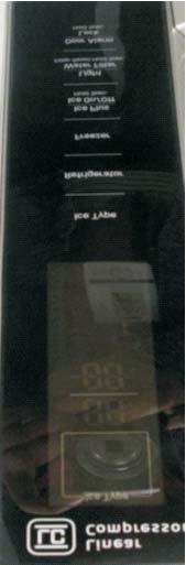
13 Micom Function 1. Operating Panel MODEL : LSXC22386* Ice Type Refrigerator Dispenser Selection Button Temperature adjustment button for refrigerator compartment Ice Plus Ice on / off Ice Plus button(1sec) Ice Making ON / OFF( 3secs) button) Door Alarm Freezer Temperature adjustment button for freezer compartment Light / Water Filter Dispenser light on/off button & filter reset button(3secs) Door Alarm Lock / Unlock button(3secs) 13
14 Micom Function 1. Operating Panel MODEL : LSXC22386* / LSXC22326* / LSXC22336* Ice Type Refrigerator Dispenser Selection Button Temperature adjustment button for refrigerator compartment Ice Plus Ice on / off Ice Plus button(1sec) Ice Making ON / OFF( 3secs) button) Door Alarm Freezer Temperature adjustment button for freezer compartment Light / Water Filter Dispenser light on/off button & filter reset button(3secs) Door Alarm Lock / Unlock button(3secs) 14
15 Micom Function 2. Function description 2-1. Funnction of Temperature Selection Power tch Temp 1st press 2nd press 3rd press 4th press 5th press 6th press 7th press 8th press 9th press 10th press 11th press 12th press Initiallly On 13th press Freezer F Refrigeration F The actual inner temperature varies depending on the food status, as the indicated setting temperature is a target temperature, not actual temperature within refrigerator. 2. Refrigeration function is weak in the initial time. Please adjust temperature as above after using refrigerator for minimum 2~3 days Automatic ice maker The automatic icemaker can automatically makes 120~ 220 cubes per day. This quantity may vary by usage condition, including ambient temperature, door opening, freezer load, and etc. Icemaker stops making ice when the ice storage bin is full. If you don t want to have the automatic icemaker make ices, press and hold ICE ON/OFF button until the indicator lights on. If you want to have icemaker makes ices again, press and hold ICE ON/OFF button until the indicator lights off. While ICE OFF indicator is on, Icemaker stops making ice. But you can dispense the ices until the ices run out from the ice storage.micom Function 2-3. When ice is not dispensed smoothly Ice is lumped together When ice is lumped together, take the ice lumps out of the ice storage bin, break them into small pieces, and then place them into the ice storage bin again. When the ice dispenser produces too small or lumped together ice, the amount of water supplied to the ice dispenser need to be adjusted. Contact the service center. If ice is not used frequently, it may lump together. Power failure Ice may drop into the freezer compartment. Take the ice storage bin out and discard all the ice then dry it and place it back. After the machine is powered again, the previous selection mode remains. The unit is newly installed It takes about 12 hours for a newly installed refrigerator to make ice in the freezer compartment Ice Plus 1. Ice Plus is function to improve cooling speed of the freezing room by consecutively operating compressors and freezing room fan. 2. Ice Plus is released if power failure occurs and then returns to the original status. 3. Temperature setting is not changed even if selecting the Ice Plus. 4. The change of temperature setting at the freezing room or the cold storage room is allowed with Ice Plus selected and processed. 5. The cold storage room operates the status currently set with Ice Plus selected and processed. 6. If selecting the Ice Plus, the Ice Plus function is released after continuously operating compressor and freezing room fan. 7. If frost removal starting time is arrived during Ice Plus, Ice Plus operation is done only for the remaining time after completion of frost removal when the Ice Plus operation time passes 90 minutes. If passing 90 minutes, Ice Plus operation is done only for 2 hours after completion of frost removal. 8. If pressing Ice Plus button during frost removal, the Ice Plus LED is turned on but if pressing the Ice Plus, compressor operates after the remaining time has passed. 9. If selection Ice Plus within 7 minutes (delay for 7 minutes of compressor) after the compressor stops, compressor operates after the remaining time has passed. 10. The freezing room fan motor operates at the high speed of RPM during operation of Ice Plus. 11. During 21 hours after Pill Down Operation, F-Room is controlled at Maximum F-tch normally and F-Fan operates normal RPM. 12. The light of Ice Plus would be turned off after Ice Plus. 13. Execute defrost immediately in case of defrost signal occurs in Ice Plus and defrosting time is included at execution time 21 hours. 14. If Ice Plus is started during 2nd Load response operation, 2nd Load response operation will be canceled. 15. If the button of Ice Plus in display is turned off, Ice Plus operation will be canceled. The compulsory operation of F notch in the water tank s preventing frost is prior to the one of Ice Plus. 15
16 Micom Function 2-5. Control of variable type of freezing room fan 1. To increase cooling speed and load response speed, MICOM variably controls freezing room fan motor at the high speed of RPM and standard RPM. 2. MICOM only operates in the input of initial power or special freezing operation or load response operation for the high speed of RPM and operates in the standard RPM in other general operation. 3. If opening doors of freezing / cold storage room or home bar while fan motor in the freezing room operates, the freezing room fan motor normally operates (If being operated in the high speed of RPM, it converts operation to the standard RPM). However, if opening doors of freezing room, the freezing room fan motor stops. 4. As for monitoring of BLDC fan motor error in the freezing room, MICOM immediately stops the fan motor by determining that the BLDC fan motor is locked or poor if there would be position signal for more than 65 seconds at the BLDC motor. Then it displays failure (refer to failure diagnosis function table) at the display part of refrigerator, performs re-operation in the cycle of 30 minutes. If normal operation is performed, poor status is released and refrigerator returns to the initial status (reset) Control of M/C room fan motor 1. The M/C room fan motor performs ON/OFF control by linking with the COMP. 2. It controls at the single RPM without varying RPM. 3. Failure sensing method is same with freezing fan motor.(refer to failure diagnosis function table for failure display) Door opening alarm 1. Buzzer generates alarm sound if doors are not closed even when more than a minute consecutively has passed with doors of freezing / cold storage room or home bar opened. 2. Buzzer rings three times in the interval of 0.5 second after the first one-minute has passed after doors are opened and then repeats three times of On/Off alarm in the cycle of every 30 seconds. 3. If all the doors of freezing / cold storage room or home bar are closed during door open alarm, alarm is immediately released. Doors of freezing / cold storage room or home bar BUZZER 2-8 Ringing of button selection buzzer 1. If pressing the front display button, Ding ~ sound rings Ringing of compulsory operation, compulsory frost removal buzzer 1. If pressing the test button in the main PCB, Phi ~ sound rings. 2. In selecting compulsory operation, alarm sound is repeated and completed in the cycle of On for 0.2 second and Off for 1.8 second three times. 3. In selecting compulsory frost removal, alarm sound is repeated and completed in the cycle of On for 0.2 second, Off for 0.2 second, On for 0.2 second and Off for 1.4 second three times. 16
17 Micom Function Function of Trouble Diagnosis(88-LED) 1. Failure diagnosis function is function to facilitate service when nonconforming matters affecting performance of product during use of product. 2. In occurrence of failure, pressing the function adjustment button does not perform function and only alarm sound ( Ding~ ) rings. 3. If nonconforming matters occurred are released during display of failure code, MICOM returns to the original state (Reset). 4. Failure code is displayed on the display part of setting temperature for the freezing room and the display part of setting temperature for the cold storage room of LED, which are placed at the display part of a refrigerator. All the LED graphics other than a failure code are turned off 17
18 Micom Function Test Function 1. Test function is function to find out any failed part in the failure status or check function of PWB and the product. 2. The test button is placed on the main PCB (test switch) of the refrigerator. The refrigerator ends the test mode after Max. 2 hours irrespective of modes and returns to normal status (reset). 3. The function control button is not detected during test mode. 4. When ending test mode, take out power cords and insert them again so as to become normal status. 5. If defect such as sensor failure during test mode is detected, release Test Mode to display failure code. 6. Test Mode is not performed even if pressing the test button during display of failure code. MODE OPERATION CONTENTS REMARKS TEST1 PRESS THEST BUTTON ONCE <STRONG COLD MODE> 1.CONTINUOUS OPERATION OF COMPRESSOR 2.CONTINUOUS OPERATION OF FREEZING BLDC MOTOR (HIGH-SPEED RPM) AND COOLING BLDC MOTOR 3.DEFROST HEATER TURNS OFF 4.STEPPING MOTOR DAMPER IS COMPLETELY OPENED (OPEN OF BAFFLE) 5.ALL DISPLAY GRAPHICS TURNS ON FREEZING FAN TURNS OFF IN DOOR OPENING. TEST2 PRESS TEST BUTTON ONCE AT THE TEST MODE 1 STATUS <FORCED DEFROST MODE> 1.COMPRESSOR OFF 2.FREEZING BLDC MOTOR AND COOLING BLDC MOTOR TURN OFF 3.DEFROST HEATER TURNS ON 4.STEPPING MOTOR DAMPER IS COMPLETELY CLOSED(CLOSING OF BAFFLE) 5.ALL DISPLAY GRAPHICS TURNS OFF(ONLY FAILURE CODE INDICATION PART TURNS ON 22 STATUS) RETURNS TO THE NORMAL MODE WHEN THE DEFROST SENSOR IS ABOVE +5 C NORMAL STATUS PRESS TEST BUTTON ONCE AT THE TEST MODE 2 STATUS RETRUING TO INITIAL STATUS COMPERSSOR WILL OPERATE AFTER DELAY FOR 3 MINUTES Functions performed when Ice Dispenser and Water Dispenser are mounted 1. This is function to dispense ice and water outside without opening doors. 2. If pressing the Dispenser Pressing Switch after selecting ice (cube ice, Crushed ice) or water, relevant ice and water come out. However, when selecting ice, the duct door is opened by electric Motor (duct door, Motor) if pressing the Dispenser Pressing Switch. The duct door is closed after it remains for 5 seconds in open status if pressing and then releasing the Dispenser Pressing Switch. 3. Function to dispense ice and water out stops in the F-door open status. 4. If there is no OFF signal for 3 minutes after pressing the Dispenser Pressing Switch after selecting ice (cube ice, crushed ice) or water, the refrigerator automatically turns off both gear motor and solenoid (cube, water). However, the Motor (duct door) stops when 5 seconds pass after turning off. (This is for preventing coil-short due to heating of solenoid.) 5. Dispenser Lamp On/Off Function If pressing the Dispenser Pressing Switch after selecting ice (cube ice, crushed ice) or water, the lamp on the dispenser part turns on and if releasing it, turns off. 6. Crushed Ice/Cube Select Function 1) This is function to operate the refrigerator as Crushed Ice/Cube function on the function control part depending on user s selection. If pressing the Select Dispenser button, display and selection are done. 2) For the initial Power On, Crushed ice is automatically selected. 3) If pressing the Press Switch when ices are generated in the ice bank for selecting Crushed Ice, the refrigerator operates the gear motor so that crushed ices are supplied outside. 4) If pressing the Press Switch when ices are generated in the ice bank for selecting Cube Ice, the refrigerator operates the gear motor so that Cube ices are supplied outside. 18
19 Micom Function 2-13 Ice on / off function Press Ice on/off Button to select Ice Making on or off. Ice on Mode in factory default setting. Ice on Ice on / off BUTTON Ice off Ice on / off BUTTON 19

20 Icemaker and dispenser working principles and repair 1. OPERATION PRINCIPLE 1-1. Operation Principle of Icemaker Power On Start Position Adjusts EJECTOR to Start Position with power on. Icemaking Mode Checking full ice Mode Waits until water becomes cold after starting the icemaking operation. Check if the ice bin is full. Harvest Mode Runs MOTOR to drop ice from the tray into the ICE BIN. Fill Water Performs Ice Making Mode after supplying water by operating the SOLENOID in ICE VALVE. Park Position With the detect lever, checks if the ICE BIN is full. Test Mode To operate LINE and SERVICE, press and hold the Test Button for 3 seconds. The icemaker will run through 3 stages: Harvest Fill Icemaking. ICE-MAKING STATUS INDICATOR Shows Ice-making status. While the indicator lights on, Icemaker stops making ice. Press and hold the ICE ON/OFF button on display for 3sec. to stop or restart making ice. While ICE OFF indicator is on, Icemaker stops making ice. But you can dispense the ices until the ices run out from the ice storage. Icemaker EJECTOR Feeler Arm 20
21 Icemaker and dispenser working principles and repair 2. Function TEST 1. CAUTION! Before you carry out the test mode, check whether the water is frozen in the icemaker completely. If the test is performed while the water is not frozen in the icemaker, The water may overflow after test and it will cause other serious problem. 2. This is a forced operation for TEST, Service, cleaning, etc. It is operated by pressing and holding the Test Button for 3 seconds. 3. The test works only in the Icemaking Mode. (This test works when the ejector and stainless lever is at the their original position.)it cannot be entered from the Harvest or Fill mode. 4. After water is supplied, the mormally CYCLE is followed : Icemaking Checking full ice Harvest Fill Water Park Position 21
22 Micom Circuit description 1. Refrigerator undercool/overcool compensation circuit Temperature compensation from cut JCR1 JCR2 JCR3 JCR Undercool compensation Overcool compensation JCR3 JCR4 JCR1 JCR2 CUT CUT CUT CUT CUT CUT CUT CUT CUT CUT CUT CUT CUT CUT CUT CUT CUT CUT CUT CUT CUT CUT CUT CUT CUT CUT Refrigerator temperature compensation 0 (Factory default) Remarks Above option circuit compensates the refrigerator temperature by simply cutting the circuit during the service. 22
23 Micom Circuit description 2. Freezer undercool compensation circuit Temperature compensation from cut JCF3 JCF Undercool compensation JCF3 JCF4 CUT CUT CUT CUT Freezer temperature compensation 0 (Factorydefault) Remarks Above option circuit compensates the freezer temperature by simply cutting the circuit during the service Communication circuit and connecting L/wire between main PCB and display PCB As the communication circuit, the following circuit exchanges information required between main MICOM of main PCB and MICOM exclusively for LED for LED control of display PCB. Sending/Receiving L/wire is required with DC12V required to operate the display PCB. Communication error occurs when the information exchange between main MICOM of main PCB and MICOM exclusively for LED for LED control of display PCB is disconnected for more than 30 seconds Main PCB L/Wire FD/H(4 wires) Display PCB Main MICOM DC 12V MICOM exclusively for LCD GND Send (Error condition) Receive (NO TCH condition) 23
24 Micom Circuit description 3. Table of sensor resistance characteristics Measured temperature Freezer sensor Refrigerator sensor 1, 2, defrost sensor, external sensor kΩ 77kΩ kΩ 60kΩ kΩ 47.3kΩ kΩ 38.4kΩ 0 7.8kΩ 30kΩ kΩ 24.1kΩ kΩ 19.5kΩ kΩ 15.9kΩ kΩ 13kΩ kΩ 11kΩ +30 2kΩ 8.9kΩ kΩ 6.2kΩ kΩ 4.3kΩ 24
25 Micom Circuit description 25
90=9.")
26 Compressor 12-1 INFORMATION OF LINEAR COMPRESSOR The information tag provides compressor model, refrigerant, serial number and safety approval Compressor Label 1. Compressor Model Series name DLF/FA/FB Displacement ex)90=9.0 /stroke Application Category - L : LBP with R134a - H : HBP with R134a - N : LBP with R600a FLB075LBNA Operating Type A : A-Inverter E : E-Inverter Rated Voltage & Frequency - M : 220V 50/60Hz - N : 115V 50/60Hz Efficiency version A:1 st generation B:2 nd generation Name Plate 2. Refrigerant 3. Serial Number Size : 90mm X 20mm Buyer Code Model Code Line Serial. Month Date 1 : January O : October ~ N : vember Year 9 : September D : December There are two types of controllers used in the linear compressor system. - The A -inverter system is used with the FLB075LBNA compressor. Refrigerator Comp Drive Compressor FLB075LBNA E-Inverter System Controls the algorithm according to various conditions. Inverter VVVF Stroke Modulation **CVCF : Variable Voltage Variable Frequency **CVCF : Constant Voltage Constant Frequency 26
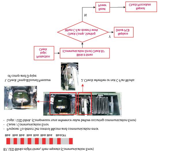
27 Compressor To reduce noise level, the piston stroke is slowly increased to full power during start up. Step 1) Start up - Half stroke interval for first 30 seconds. Step 2) Ramp up - Stroke increases every 0.8sec until maximum stroke length is reached (about 3 min, 15 sec) Step 3) CVCF interval - 180V / 60Hz Step 1) Start up - Half stroke interval for first 20 seconds. Step 2) Ramp up - Stroke increases until maximum stroke length is reached (about 1 min, 40 sec) Step 3) VVCF interval - target voltage and frequency controlled by Control Board signals There are 6 protection logics designed to protect the linear compressor system. When a failure is detected, the compressor will shut and will try to restart after a set period of time for each type of failure. The LED located on the inverter drive PCB will flash the appropriate code to indicate the detected failure. This code will continue to flash until the unit is disconnected from the power source. Inverter Error Codes Inverter Error Codes code Requirement Off Time The number of LED flashes FCT0 5 Vm, Im > COMP off 30s 1 Stroke 10 Stroke >17.5mm 60s 2 Connect 15 Stroke <=9.4mm & While 4 seconds AC Current <0.05A 40s 3 Lock 25 AC Current >1.0A & Stroke <3.0mm 150s 5 Current 30 Current >3Ap 360s 6 IPM 35 uc_fo_trip!= 0 20S 7 Communication Error - Checksum error

 Display ON, Buzz 1")
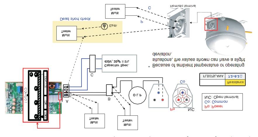
28 Compressor Power off CON201 Disconnect Power ON Time>30sec Y& V 200 PCB OK Replace drver PCB Ref. Comp FLB075(A-Inverter) Display & sound Refer TEST1 Forced Starting TDC (Full Stroke) Display ON, Buzz 1 time 28


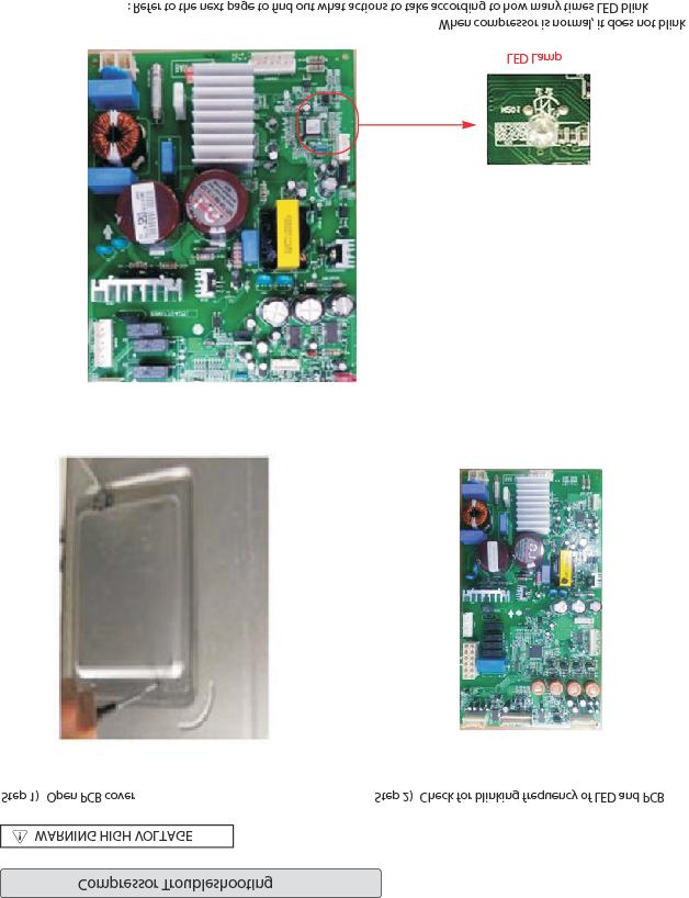
29 Compressor 12-1 Check A Dear is PC board located in the PCB case. The control driver is PC board for the compressor. This step shows the source voltage of the driver PC board. Step 1. Open PCB Cover Step 2. Check Driver PCB * Driver PCB located in machine room. 29
 Blink OFF Blink OFF - Purpose: Detecting motor current and voltage error - Check voltage at point A (Motor Voltage), point B (Motor Current) and")
 Y Replace Driver PCB N Reset Power Caution : Devices should not be shortcircuited during check C B GND B2.")

30 Compressor 12-1 Check B B1. LED blinks once, then repeats (FCT0 Fault: A-Inverter) Blink OFF Blink OFF - Purpose: Detecting motor current and voltage error - Check voltage at point A (Motor Voltage), point B (Motor Current) and Point C (Capacitor Voltage) when compressor is off. - Spec: Points A, B, & C 2.5V 0.3V Protection Logic Protection logic Check B Blink 1 time (FCT 0) Check B1 Out of spec? ( V) Y Replace Driver PCB N Reset Power Caution : Devices should not be shortcircuited during check C B GND B2. LED blinks two times, then repeats (Stroke Trip) C A Blink Blink OFF Blink Blink OFF - Purpose: Prevent abnormally long piston strokes. - Case 1. If compressor doesn t work and LED blinks - Cause: Possibly harness from compressor to PCB might be defective. - Case 2. If compressor works intermittently and LED blinks - Cause: Condenser Fan or Freezer Fan is not running. Sealed system problem such as moisture restriction, restriction at capillary tube or refrigerant leak. - Logic: Compressor is forced to off and then tries to restart after 1 minute. Protection logic Check B Blink 2 times (Stroke Trip) Check B2 N Fix Harness Replace Driver PCB OK Compressor doesn t work N Y Harness Connecting Check C Compressor works intermittently Y Y Capacitor spec. Check C N Replace capacitor Fix Cycle NG Cycle Check E Y Y Repeat check procedure N Stroke trip occur? Reset power Compressor Damage Check C Y N Replace compressor 30
31 Compressor 31


32 Compressor Protection logic Check B blink 6 times (Current Trip)check B5 Compressor Intermittently Works Y N Replace Driver PCB N IPM Check Y Compressor Damage Check N Replace Compressor Repeat Check Procedure N Current trip occur? Reset Power Y Y Compressor Doesn t works Y Cycle blockage? N Replace Compressor N Cycle check Y Sealed system Repair 32
33 Compressor 33
34 Compressor 34
35 Compressor 35
36 Troubleshooting PCB 1. PCB Picture - Main PCB ( P/N : EBR809775**) CON6 CON5 CON4 CON3 CON7 CON201 CON1 36
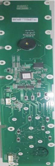
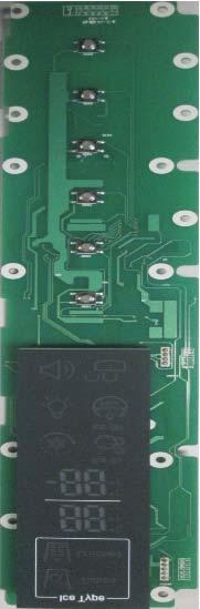
37 Troubleshooting 2. Display PCB ( P/N : EBR790695**) CON101 37
38 Troubleshooting with Error Display 1. Freezer Sensor Error Symptom Check Point 1. E FS 1. Check for a loose connection 2. Check Sensor Resistance ( P/N EBR809775**) CON7 CON201 CON6 CON5 CON4 CON1 CON3 Resistance [Ω] 23 th pin ~ 24 th pin Short 0 Open OFF Other rmal 23 th pin ~ 24 th pin -22ºF / -30ºC -13ºF / -25ºC -4ºF / -20ºC Resistance [Ω] 40k 30k 23k 5ºF / -15ºC 17k 14ºF / -10ºC 13k 23ºF / -5ºC 10k 32ºF / 0ºC 8k 38
39 Troubleshooting Freezer Sensor Error (E FS) 1 Is the Connector disconnected or loose between Main PCB and sensor? Reconnect or repair the connector 4 Check the Sensor resistance. Is resistance normal? 5 Check the Temperature and resistance refer to the table. problem? 23 th pin ~ 24 th pin Resistance [Ω] 2 Check the Sensor resistance. Is resistance 0Ω (Sensor short)? Change the Sensor -22ºF / -30ºC -13ºF / -25ºC -4ºF / -20ºC 40k 30k 23k 5ºF / -15ºC 17k 14ºF / -10ºC 13k 23ºF / -5ºC 10k 32ºF / 0ºC 8k 6 3 Check the Sensor resistance. Is resistance OFF (Sensor open)? Replace the refrigerator Explain to customer 39
40 Troubleshooting 2. Refrigerator Sensor Error (E rs) Symptom Check Point 1. E rs 1. Check for a loose connection 2. Check Sensor Resistance ( P/N EBR809775**) CON7 CON201 CON6 CON5 CON4 CON1 CON7 CON3 Resistance [Ω] CON7 19 th pin ~ 20 th pin Short 0 Open OFF Other rmal CON7 19 th pin ~ 20 th pin Resistance [Ω] 23ºF / -5ºC 38k 32ºF / 0ºC 30k 41ºF / 5ºC 24k 50ºF / 10ºC 19.5k 59ºF / 15ºC 16k 40
41 Troubleshooting Refrigerator Sensor Error (E rs) 1 Is the Connector disconnected or loose between Main PCB and sensor? Reconnect or repair the connector 4 Check the Sensor resistance. Is resistance normal? 5 Check the Temperature and resistance refer to the table. problem? CON7 CON7 19 th pin ~ 20 th pin Resistance [Ω] 2 Check the Sensor resistance. Is resistance 0Ω (Sensor short)? Change the Sensor 23ºF / -5ºC 38k 32ºF / 0ºC 30k 41ºF / 5ºC 24k 50ºF / 10ºC 19.5k 59ºF / 15ºC 16k CON7 3 Check the Sensor resistance. Is resistance OFF (Sensor open)? Replace the refrigerator 6 Explain to customer 41
 CON7 CON201 CON6 CON5 CON4 CON1 CON7 CON3 Resistance [Ω] CON7 17 th pin ~18 th pin Short 0 Open OFF Other rmal CON7 17 th pin ~18 th pin Resistance [Ω]")
42 Troubleshooting 2. Refrigerator Sensor Error (E r2) Symptom Check Point 1. E r2 1. Check for a loose connection 2. Check Sensor Resistance ( P/N EBR809775**) CON7 CON201 CON6 CON5 CON4 CON1 CON7 CON3 Resistance [Ω] CON7 17 th pin ~18 th pin Short 0 Open OFF Other rmal CON7 17 th pin ~18 th pin Resistance [Ω] 23ºF / -5ºC 38k 32ºF / 0ºC 30k 41ºF / 5ºC 24k 50ºF / 10ºC 19.5k 59ºF / 15ºC 16k 42
43 Troubleshooting Refrigerator Sensor Error ( E r2) 1 Is the Connector disconnected or loose between Main PCB and sensor? Reconnect or repair the connector 4 Check the Sensor resistance. Is resistance normal? 5 Check the Temperature and resistance refer to the table. problem? CON7 CON7 17 th pin ~ 18 th pin Resistance [Ω] 2 Check the Sensor resistance. Is resistance 0Ω (Sensor short)? Change the Sensor 23ºF / -5ºC 38k 32ºF / 0ºC 30k 41ºF / 5ºC 24k 50ºF / 10ºC 19.5k 59ºF / 15ºC 16k CON7 3 Check the Sensor resistance. Is resistance OFF (Sensor open)? Replace the refrigerator 6 Explain to customer 43
44 Troubleshooting 3. Room Temperature Sensor Error Symptom Check Point 1. E rt 1. Check for a loose connection 2. Check Sensor Resistance ( P/N EBR809775**) CON7 CON201 CON6 CON5 CON4 CON1 CON3 CON5 Resistance [Ω] CON5 13 th pin ~ 14 th pin Short 0 Open OFF Other rmal CON5 13 th pin ~ 14 th pin Resistance [Ω] 32ºF / 0ºC 30k 50ºF / 10ºC 20k 60ºF /16ºC 15k 68ºF / 20ºC 13k 79ºF / 26ºC 10k 86ºF / 30ºC 9k 44
?")
45 Troubleshooting Room Temperature (E rt) Sensor Error 1 Is the Connector disconnected or loose between Main PCB and sensor? Reconnect or repair the connector 4 Check the Sensor resistance. Is resistance normal? 5 Check the Temperature and resistance refer to the table. problem? CON5 2 Check the Sensor resistance. Is resistance 0Ω (Sensor short)? Change the Sensor CON5 13 th pin ~ 14 th pin Resistance [Ω] 32ºF / 0ºC 30k 50ºF / 10ºC 20k 60ºF /16ºC 15k 68ºF / 20ºC 13k 79ºF / 26ºC 10k 86ºF / 30ºC 9k CON5 6 3 Check the Sensor resistance. Is resistance OFF (Sensor open)? Replace the refrigerator Explain to customer 45
 CON7 CON201 CON6 Ice Maker Connector CON5 CON4 CON1 CON3 CON6 Resistance [Ω] CON6 5 st pin ~ 12 th pin Short 0 Open OFF Other rmal CON6 5 st pin ~ 12 th pin")
46 Troubleshooting 4. Icing Sensor Error Symptom Check Point 1. E IS 1. Check for a loose connection 2. Check Sensor Resistance ( P/N EBR809775**) CON7 CON201 CON6 Ice Maker Connector CON5 CON4 CON1 CON3 CON6 Resistance [Ω] CON6 5 st pin ~ 12 th pin Short 0 Open OFF Other rmal CON6 5 st pin ~ 12 th pin -22ºF / -30ºC -13ºF / -25ºC -4ºF / -20ºC -13ºF / -25ºC Resistance [Ω] 40k 30k 23k 17k 14ºF / -10ºC 13k 23ºF / -5ºC 10k 32ºF / 0ºC 8k 46
?")
47 Troubleshooting Icing Sensor Error (E IS ) 1 Is the Connector disconnected or loose between Main PCB and sensor? Reconnect or repair the connector 4 Check the Sensor resistance. Is resistance normal? 5 Check the Temperature and resistance refer to the table. problem? CON6 Ice Maker Connector CON6 5 st pin ~ 12 th pin Resistance [Ω] 2 Check the Sensor resistance. Is resistance 0Ω (Sensor short)? Change the Sensor -22ºF / -30ºC -13ºF / -25ºC -4ºF / -20ºC -13ºF / -25ºC 40k 30k 23k 17k 14ºF / -10ºC 13k 23ºF / -5ºC 10k 32ºF / 0ºC 8k CON6 3 Check the Sensor resistance. Is resistance OFF (Sensor open)? Replace the refrigerator 6 Explain to customer 47
48 5. Defrost Sensor Error Symptom Check Point 1. F ds 1. Check for a loose connection 2. Check Sensor Resistance ( P/N EBR809775**) CON7 CON201 CON6 CON5 CON4 CON1 CON3 Resistance [Ω] 21 th pin ~ 22 th pin Short 0 Open OFF Other rmal 21 th pin ~ 22 th pin Resistance [Ω] 23ºF / -5ºC 38k 32ºF / 0ºC 30k 41ºF / 5ºC 24k 50ºF / 10ºC 19.5k 59ºF / 15ºC 16k 48

![problem? 21 th pin ~ 22 th pin Resistance [Ω] 2 Check the Sensor resistance. Is resistance 0Ω (Sensor short)?](/docs-images/90/103457921/images/49-1.jpg "Change the Sensor 23ºF / -5ºC 38k 32ºF / 0ºC 30k 41ºF / 5ºC 24k 50ºF / 10ºC 19.5k 59ºF / 15ºC 16k 6 3 Check the Sensor resistance.")
49 Troubleshooting Icing Sensor Error (F ds) 1 Is the Connector disconnected or loose between Main PCB and sensor? Reconnect or repair the connector 4 Check the Sensor resistance. Is resistance normal? 5 Check the Temperature and resistance refer to the table. problem? 21 th pin ~ 22 th pin Resistance [Ω] 2 Check the Sensor resistance. Is resistance 0Ω (Sensor short)? Change the Sensor 23ºF / -5ºC 38k 32ºF / 0ºC 30k 41ºF / 5ºC 24k 50ºF / 10ºC 19.5k 59ºF / 15ºC 16k 6 3 Check the Sensor resistance. Is resistance OFF (Sensor open)? Replace the refrigerator Explain to customer 49
 CON7 CON201 CON6 CON5 CON4 CON1 CON3 CON3 Part Resistance [Ω] FUSE-M 0 Defrost Heater 48~54 Defrost Sensor 22k TEST MODE 2 CON3 5 nd pin ~ 6 th pin")
50 Troubleshooting 6. Defrost Heater Error Symptom Check Point 1. F dh 1. Check the heater disconnect 2. Check the Fuse hire 3. Check Drain stuck 4. Check the PCB output voltage ( P/N EBR809775**) CON7 CON201 CON6 CON5 CON4 CON1 CON3 CON3 Part Resistance [Ω] FUSE-M 0 Defrost Heater 48~54 Defrost Sensor 22k TEST MODE 2 CON3 5 nd pin ~ 6 th pin Voltage [V] 112V ~ 116V TEST MODE 1 CON3 5 nd pin ~ 6 th pin Voltage [V] 0V 50
51 Troubleshooting Defrost Heater Error ( FdH) 1 Check the Door gasket. Is door gasket damaged? Replace the Door gasket 4 Input Test 2 Mode (Push the button 2 times) Check the Heater Voltage. Is voltage 112~116V? NO Replace Main PCB 2 Check the Defrost control part. (1) Is Fuse-M resistance 0 Ω? (2) Is Defrost Heater resistance 48~54Ω? Change Fuse-M TEST MODE 2 CON3 5 nd pin ~ 6 th pin CON3 Voltage [V] 112V ~ 116V 5 Input Test 1 Mode (Push the button 1 time) Check the Heater Voltage. Is voltage 0V? Replace Main PCB 3 Check the Defrost control part. Is Defrost Sensor resistance 22kΩ or OFF? OFF Replace product TEST MODE 1 CON3 5 nd pin ~ 6 th pin CON3 Voltage [V] 0V 6 Explain to customer 22kΩ 51


52 Troubleshooting 7. Freezer Fan Error (Er FF) Symptom Check Point 1.- E FF 1. Check the air flow 2. Check the Fan Motor 2. Check the PCB Fan motor voltage ( P/N EBR809775**) CON7 CON201 CON6 CON5 Fan Motor CON4 CON1 CON3 TEST MODE 1 9 th pin ~ 12 th pin 9 th pin ~ 19 th pin 9 th pin ~ 10 th pin Voltage [V] 10~12 VDC 2~4.5 VDC t 0V, 5V 52
 TEST MODE 1 Voltage [V] 9 th pin ~ 12 th pin 10~12 VDC 2 Open the freezer door and Check the air flow. Windy? Go to 3 5 Check the Fan Motor voltage Is Fan PWM voltage 2~4.5V?")
53 Troubleshooting Freezer Fan Error (E FF) 4 Check the Fan Motor voltage Is Fan Motor voltage 10~12V? Replace Main PCB 1 Reset the unit and Input Test1 Mode. (Push the button 1 time) TEST MODE 1 Voltage [V] 9 th pin ~ 12 th pin 10~12 VDC 2 Open the freezer door and Check the air flow. Windy? Go to 3 5 Check the Fan Motor voltage Is Fan PWM voltage 2~4.5V? Replace Main PCB TEST MODE 1 9 th pin ~ 19 th pin Voltage [V] 2~4.5 VDC Go to 4 5 Check the Fan Motor voltage Is Fan Feed Back voltage 0V,5V? Change the motor 3 Check the Fan motor. Rotate fan using hand. It feel sticky? Change the Fan motor TEST MODE 1 Voltage [V] Fan Motor 9 th pin ~ 10 th pin t 0V, 5V 6 Explain to customer 53
 CON7 Fan Motor CON201 CON6 CON5 CON4 CON1 CON3 TEST MODE 1 11 th pin ~ 16 th pin 11 th pin ~ 20 th pin 11 th pin ~ 14 th pin")
54 Troubleshooting 8. Condenser Fan Error (E CF) Symptom Check Point 1.- E CF 1. Check the air flow 2. Check the fan motor and connector 2. Check the PCB Fan motor voltage ( P/N EBR809775**) CON7 Fan Motor CON201 CON6 CON5 CON4 CON1 CON3 TEST MODE 1 11 th pin ~ 16 th pin 11 th pin ~ 20 th pin 11 th pin ~ 14 th pin Voltage [V] 10~12 VDC 2~4.5 VDC t 0V, 5V 54
55 Troubleshooting Condenser Fan Error ( E CF) 4 Check the Fan Motor voltage Is Fan Motor voltage 10~12V? Replace Main PCB 1 Reset the unit and Input Test1 Mode. (Push the button 1 time) TEST MODE 1 Voltage [V] 11 th pin ~ 16 th pin 10~12 VDC 2 Check the fan rotating. Does fan rotate? Go to 3 5 Check the Fan Motor voltage Is Fan PWM voltage 2~4.5V? Replace Main PCB Fan Motor TEST MODE 1 11 th pin ~ 20 th pin Voltage [V] 2~4.5 VDC Go to 4 5 Check the Fan Motor voltage Is Fan Feed Back voltage 0V,5V? Change the motor 3 Check the Fan motor. Rotate fan using hand. It feel sticky? Fan Motor Change the Fan motor TEST MODE 1 Voltage [V] 11 th pin ~ 14 th pin t 0V, 5V 6 Explain to customer 55


56 9. Communication Error (E CO). Checking flow Result & SVC Action 1 Check the loose connection 2 Check the Yellow to Blue. 3 Check the Blue to Brown 4 Check the Red to Blue. 5 Check the pin15 to pin18 of CON5 6 Check the pin15 to pin17 of CON5 56
57 10. Ice Maker Motor Error (E It) Symptom Check Point 1. E It 1. Check for a loose connection 2. Check Sensor Resistance ( P/N EBR809775**) CON7 CON201 CON6 CON5 CON4 CON1 CON3 CON6 Housing CON6 7 th pin ~ 8 th pin CON6 9 th pin ~ 10 th pin Resistance [Ω] 374~ ~456 57

58 Ice Maker Motor Error ( E It) 1 Input Ice Maker test mode(push The ice maker test button),check The Ice Tray,Ice maker motor Rotate? Wait until 1 minute Explain to customer 3 Disconnect housing of Main PCB And check resistance between Pink and blue wires. Is Motor resistance 374~456Ω? Change the ICE Maker Unit CON6 2 Is the Connector disconnected or loose between Main PCB and ICE Maker? Reconnect or repair the connector Disconnect housing of Main PCB And check resistance between Purple and yellow wires. Is Motor resistance 374~456Ω? Change the ICE Maker Unit CON6 CON6 Change the Main PCB 58

 CON7 CON201 CON6 CON5")
59 Troubleshooting without Error Display 1. Cube mode doesn t work Symptom Check Point 1. Cube mode doesn t work 1. Check the loose connection 2. Check the resistance ( P/N EBR809775**) CON7 CON201 CON6 CON5 CON4 CON1 CON3 Duct Motor Ice Maker Auger Motor 59
60 1. Cube mode doesn t work INSPECTION POINT ICE/Water Lever SW CON6 19 th pin ~ 20 th pin Duct Motor CON6 23 th pin ~ 24 th pin Auger Motor CON3 4 th pin ~ 8 th pin ICE / Water LEVER S/W Result Pushing 0~2V t Pushing 3.5~5V Pushing 9~12V t Pushing 0~2V Pushing 112~115V t Pushing 0~2V Motor Type Resistance [Ω] Auger Motor 33~ 37 Duct Motor 9.9 ~
61 1. Cube mode doesn t work 4 Check the resistance value. Is Dispenser Motor resistance 9.9 ~ 12.1Ω? Replace Geared Motor Cube mode doesn't work 1 Check the loose connection Dispenser Motor 2 Check the voltage. (while pushing the lever S/W) Is voltage correct compared with table? Change the PCB Resistance [Ω] Dispenser Motor 9.9 ~ 12.1 CON6 5 Check the voltage. (while pushing the lever S/W) Is voltage correct compared with table? Change the PCB INSPECTION POINT LEVER S/W RESULT ICE Lever SW CON6 19 th pin ~ 20 th pin Pushing 0~2V t Pushing 3.5~5V INSPECTION POINT LEVER S/W CON3 RESULT 3 Check the voltage. Is Duct Motor voltage correct compared with table? Change the PCB Auger Motor CON3 4 nd pin ~ 8 th pin Pushing 112~115V t Pushing 4 Check the resistance value. Is Auger Motor resistance 33 ~ 37Ω? 0~2V Replace Geared Motor CON6 Auger Motor Duct Motor Duct Motor CON6 23 th pin ~ 24 th pin Voltage [V] Pushing 9~12V t Pushing 0~2V Geared Motor Black / white Harness Resistance [Ω] 33 ~ 37 6 Explain to customer 61
 CON7 CON201 CON6 CON5 CON4 CON1 CON3 Duct Motor Ice Maker Auger Motor")
62 2. Crush mode doesn t work Symptom Check Point 1. Crush mode doesn t work 1. Check the loose connection 2. Check the resistance ( P/N EBR809775**) CON7 CON201 CON6 CON5 CON4 CON1 CON3 Duct Motor Ice Maker Auger Motor 62
63 2. Crush mode doesn t work INSPECTION POINT ICE/Water Lever SW CON6 19 th pin ~ 20 th pin Duct Motor CON6 23 th pin ~ 24 th pin Auger Motor CON3 4 th pin ~ 7 th pin ICE / Water LEVER S/W Result Pushing 0~2V t Pushing 3.5~5V Pushing 9~12V t Pushing 0~2V Pushing 112~115V t Pushing 0~2V Motor Type Resistance [Ω] Auger Motor 23~27 Duct Motor 9.9 ~
 Is voltage correct compared with table?")
64 2. Crush mode doesn t work 4 Check the resistance value. Is Dispenser Motor resistance 9.9 ~ 12.1Ω? Replace Geared Motor Crush mode doesn't work 1 Check the loose connection Dispenser Motor 2 Check the voltage. (while pushing the lever S/W) Is voltage correct compared with table? Change the PCB Resistance [Ω] Dispenser Motor 9.9 ~ 12.1 CON6 5 Check the voltage. (while pushing the lever S/W) Is voltage correct compared with table? Change the PCB INSPECTION POINT LEVER S/W RESULT ICE/Water Lever SW CON6 19 th pin ~ 20 th pin Pushing 0~2V t Pushing 3.5~5V INSPECTION POINT LEVER S/W CON3 RESULT 3 Check the voltage. Is Duct Motor voltage correct compared with table? Change the PCB Auger Motor ( CON3 4 th pin ~ 7 th pin Pushing 112~115V t Pushing 4 Check the resistance value. Is Auger Motor resistance 23~27Ω? 0~2V Replace Geared Motor CON6 Auger Motor Duct Motor Duct Motor CON6 23 th pin ~ 24 th pin Voltage [V] Pushing 9~12V t Pushing 0~2V Geared Motor Black / White Harness Resistance [Ω] 23~27 6 Explain to customer 64
 (1) (2) (3) (4) Water Valve(RD) Pilot Valve (GY) CON3 Pilot Valve Machine Room Water Valve")

65 3. Water mode doesn t work Symptom Check Point 1. Water mode doesn t work 1. Check the loose connection 2. Check the resistance valve Ground (BL) (1) (2) (3) (4) Water Valve(RD) Pilot Valve (GY) CON3 Pilot Valve Machine Room Water Valve INSPECTION POINT Water LEVER S/W Result Water Lever SW CON6 19 th pin ~ 20 th pin Pilot Valve CON3 2 nd pin ~ 11 th pin Water valve CON3 2 nd pin ~ 10 th pin Pushing 0~2V t Pushing 3.5~5V Pushing 112~115V t Pushing 0~2V Pushing 112~115V t Pushing 0~2V Resistance [Ω] Pilot Valve 390~450 Water valve 330~390 65
 Is voltage correct compared with table?")
![Change the PCB Pilot Valve Valve Resistance [Ω] INSPECTION POINT CON6 LEVER S/W RESULT Pilot Valve 390~450 ICE/Water Lever SW CON6 19 th pin ~ 20 th pin Pushing 0~2V t Pushing 3 Check the voltage.](/docs-images/90/103457921/images/66-2.jpg "Valves voltage correct compared with table? 3.5~5V Change the PCB 4 Check the resistance value. Is Water Valve resistance 360~390 Ω?")
66 Water mode doesn t work 1 Check the loose connection 3 Check the resistance value. Is Pilot Valve resistance 390~450 Ω? Replace Water Valve 2 Check the voltage. (while pushing the lever S/W) Is voltage correct compared with table? Change the PCB Pilot Valve Valve Resistance [Ω] INSPECTION POINT CON6 LEVER S/W RESULT Pilot Valve 390~450 ICE/Water Lever SW CON6 19 th pin ~ 20 th pin Pushing 0~2V t Pushing 3 Check the voltage. Valves voltage correct compared with table? 3.5~5V Change the PCB 4 Check the resistance value. Is Water Valve resistance 360~390 Ω? Replace Water Valve Water Valve INSPECTION POINT Pilot Valve CON3 2 nd pin ~ 11 th pin Water valve CON3 2 nd pin ~ 10 th pin Water LEVER S/W Result Pushing 112~115V t Pushing 0~2V Pushing 112~115V t Pushing 0~2V Valve Resistance [Ω] Water valve 330~390 5 Explain to customer 66
67 4. Refrigerator room led doesn t work Symptom 1. Refrigerator room led doesn t work Check Point 1. Check the refrigerator door switch sticky 2. Check the door S/W resistance 3. Check the LED Lamp Door S/W CON5 (R-Door S/W) CON7 (R-LED Supply) R Led Lamp Resistance [Ω] Door S/W Open Infinity Closed 0 INSPECTION POINT DOOR Voltage [V] CON7 7 th pin ~ 8 th pin LED Lamp Blue~ Black Close 0~2V Open 12V Voltage [V] Closed 0~2V Open 12V 67
 Change the Door S/W 2 Check the door S/W resistance. Is it correct compared with table?")
 Change the LED Lamp Door S/W Door S/W Resistance [Ω] rmal Infinity Door Close 0 6 Explain to customer 3 Check the PCB Voltage.")
68 Refrigerator room lamp doesn t work 1 Check the Freezer door switch. Does it feel sticky? Change the Door S/W 4 Check the LED Lamp voltage. Is it 0~2V? (While door closed) Change the Door S/W 2 Check the door S/W resistance. Is it correct compared with table? Change the Door S/W 5 Check the LED Lamp voltage. Is it 12V? (While door open) Change the LED Lamp Door S/W Door S/W Resistance [Ω] rmal Infinity Door Close 0 6 Explain to customer 3 Check the PCB Voltage. Is CON7 7th pin ~ 8th pin voltage 12V? Change the PCB CON7 INSPECTION POINT DOOR Voltage [V] CON7 7 th pin ~ 8 th pin Close 0~2V Open 12V 68
69 5. Freezer room led doesn t work Symptom 1. Freezer room led doesn t work Check Point 1. Check the freezer door switch sticky 2. Check the door S/W resistance 3. Check the LED Lamp Door S/W CON5 (F-Door S/W) (F-LED Supply) F Led Lamp Resistance [Ω] Door S/W Open Infinity Closed 0 INSPECTION POINT DOOR Voltage [V] 17 th pin ~ 18 th pin LED Lamp Blue~ Black Close 0~2V Open 12V Voltage [V] Closed 0~2V Open 12V 69
70 Freezer room lamp doesn t work 1 Check the Refrigerator door switch. Does it feel sticky? Change the Door S/W 4 Check the LED Lamp voltage. Is it 0~2V? (While door closed) Change the Door S/W 2 Check the door S/W resistance. Is it correct compared with table? Change the Door S/W 5 Check the LED Lamp voltage. Is it 12V? (While door open) Change the LED Lamp Door S/W Door S/W Resistance [Ω] rmal Infinity Door Close 0 6 Explain to customer 3 Check the PCB Voltage. Is 17 th pin ~ 18 th pin voltage 12V? Change the PCB INSPECTION POINT DOOR Voltage [V] 17 th pin ~ 18 th pin Close 0~2V Open 12V 70

![Check the R-Damper motor voltage Duct CON7 Fan Motor CON6 R1SNR 5 th pin ~ 6 th pin Resistance [Ω] R1Sensor 23ºF /-5ºC 38k 32ºF / 0ºC 30k](/docs-images/90/103457921/images/71-4.jpg "41ºF / 5ºC 24k 50ºF / 10ºC 19.")
71 6. Poor/Over cooling in Fresh food section Symptom 1. Poor cooling in Fresh food section Check Point 1. Check the sensor resistance 2. Check the air flow 3. Check the air Temperature 4. Check the R-Damper motor voltage Duct CON7 Fan Motor CON6 R1SNR 5 th pin ~ 6 th pin Resistance [Ω] R1Sensor 23ºF /-5ºC 38k 32ºF / 0ºC 30k 41ºF / 5ºC 24k 50ºF / 10ºC 19.5k R-Damper 59ºF / 15ºC 16k TEST MODE 1 Voltage [V] 9 th pin ~ 12 th pin 9 th pin ~ 19 th pin 9 th pin ~ 10 th pin 10~12 VDC 2~4.5 VDC t 0V, 5V F-Fan motor Duct Air Flow Air Temperature Status Windy Cold 71
72 Poor cooling in Fresh food section 4 Check the air temperature. Is it cold? Check the Compressor and sealed system Go to 8 1 Check the sensor resistance. 5 Check the Fan Motor voltage Is Fan Motor voltage 10~12V? Replace Main PCB CON6 R1SNR 5 th pin ~ 6 th pin Resistance [Ω] 23ºF /-5ºC 38k 32ºF / 0ºC 30k 41ºF / 5ºC 24k 50ºF / 10ºC 19.5k 59ºF / 15ºC 16k CON7 TEST MODE 1 9 th pin ~ 12 th pin Voltage [V] 10~12 VDC 2 Reset the unit and Input Test1 Mode (Push the button 1 time) 6 Check the Fan Motor voltage Is Fan PWM voltage 2~4.5V? Replace Main PCB 3 Open the fresh food door and Check the air flow D amper? Check the damper Go to 5 TEST MODE 1 9 th pin ~ 19 th pin Voltage [V] 2~4.5 VDC 7 Check the Fan Motor voltage Is Fan Feed Back voltage 0V,5V? Change the motor TEST MODE 1 9 th pin ~ 10 th pin Voltage [V] t 0V, 5V 8 Explain to customer 72
73 7. Poor cooling in Freezer compartment Symptom Check Point 1. Poor cooling in Freezer compartment 1. Check the sensor resistance 2. Check the air flow 3. Check the air Temperature 4.Check the Fan motor sticky 4. Check the Fan motor voltage Duct Fan Motor F-Sensor 23 th pin ~ 24 th pin -22ºF / -30ºC -13ºF / -25ºC Resistance [Ω] 40k 30k TEST MODE 1 9 th pin ~ 12 th pin 9 th pin ~ 19 th pin 9 th pin ~ 10 th pin Voltage [V] 10~12 VDC 2~4.5 VDC t 0V, 5V -4ºF / -20ºC 23k 5ºF / -15ºC 17k 14ºF / -10ºC 13k 23ºF / -5ºC 10k 32ºF / 0ºC 8k F fan motor Duct Air Flow Air Temperature Status Windy Cold 73
74 7) Poor cooling in Freezer compartment Poor cooling in Freezer compartment 1 Check the sensor resistance. 3 Open the fresh food door and Check the air flow. Windy? Check the F Fan Motor Go to 5 23 th pin ~ 24 th pin -22ºF / -30ºC -13ºF / -25ºC -4ºF / -20ºC Resistance [Ω] 40k 30k 23k 5ºF / -15ºC 17k 14ºF / -10ºC 13k 23ºF / -5ºC 10k 32ºF / 0ºC 8k 4 Check the air temperature. Is it cold? Check the Compressor and sealed system 2 Open the fresh food door and Check the air flow D amper? Check the damper Go to 4 5 Check the Fan motor. Rotate fan using hand. It feel sticky? Change the Fan motor Fan Motor 74
75 6 Check the Fan Motor voltage Is Fan Motor voltage 10~12V? Replace Main PCB TEST MODE 1 9 th pin ~ 12 th pin Voltage [V] 10~12 VDC 7 Check the Fan Motor voltage Is Fan PWM voltage 2~4.5V? Replace Main PCB TEST MODE 1 9 th pin ~ 19 th pin Voltage [V] 2~4.5 VDC 8 Check the Fan Motor voltage Is Fan Feed Back voltage 0V,5V? Change the motor TEST MODE 1 9 th pin ~ 10 th pin Voltage [V] t 0V, 5V 9 Explain to customer 75


 1.")

 When the COMP & FAN are not operating")
76 Troubleshooting 1. COMP operation error Open the PWB COVER 3 2.Check the number of LED blinks (Refer to the next page for resolution by number of LED blinks When the COMP is normal, it will not blink 1.Open the BACK COVER 4 3.Check the COMP connector voltage (Measure without pulling the HOUSING) 1.Check the temperature and noise of COMP and discharge outlet 2.Check whether the C-FAN is operating BLACK & RED PS :Check the voltage during C- Fan operation. (About AC 10V~ AC 230V) When the COMP & FAN are not operating simultaneously, force operate from the MAIN PCB in TEST MODE to check whether it is operating and then check the power of the COMP end to reset the power. 76
77 Troubleshooting 2. Resolution by number of LED blinks. LED operating condition Cause Service guide 1 LED blinking 1 time repeatedly Blink -Off-Blink-Off-Blink-Off-Blink-Off-Blink-Off Repeat PCB part defect (MICOM) 1. After resetting the power check normal operation 2. When the same symptom occurs again after taking action for 1, replace the PCB 2 LED blinking 1 time repeatedly PCB part defect (Piston over-operation) 1.After resetting the power check normal operation 2.When the same symptom occurs again after taking action for 1, replace the PCB 3 LED blinking 3 time repeatedly Power voltage defect) 1.Check input power 2.After resetting the power check normal operation 3.When the same symptom occurs again after taking action for 1 and 2 replace the PCB 4 LED blinking 4 time repeatedly COMP cable contact error 1.Check connected condition between PCB and COMP 2.When there is no issue with 1, replace the PCB 5 LED blinking 5 time repeatedly Piston lock 1.After resetting the power check normal operation 2.When the same symptom occurs again after taking action for 1, replace the PCB 3. When the same symptom occurs again after taking action for 2, replace the COMP component 6 LED blinking 6 time repeatedly Circuit overcurrent error 1.After resetting the power check normal operation 2.When the same symptom occurs again after taking action for 1, replace the PCB 3.When the same symptom occurs again after taking action for 2, replace the COMP component 7 8 LED blinking 7 time repeatedly LED blinking 8 time repeatedly PCB part defect (IPM) Communication error 1.After resetting the power check normal operation 2.When the same symptom occurs again after taking action for 1, replace the PCB 1.After resetting the power check normal operation 2.When the same symptom occurs again after taking action for 1, replace the PCB 77
 TEST MODE and Removing TPA 1.")

 * 2 times :Forced defrost mode (22 22")
 <AC TPA>")

78 Troubleshooting 3. Reference 1) TEST MODE and Removing TPA 1.How to make TEST MODE If you push the test button on the Main PCB, the refrigerator will be enter the TEST MODE * 1 time :Comp / Damper / All FAN on (All things displayed) * 2 times :Forced defrost mode (22 22 displayed) Main PWB 2. How to remove Terminal Position Assurance (TPA) <AC TPA> <DC TPA> After measure the values, you should put in the TPA again. 3. Wire Color BL : Blue WH :White BO : Bright Orange BK : Black BN : Brown PR : Purple RD : Red GN : Green SB : Sky Blue GY : Gray PK : Pink 78
79 Troubleshooting 2) TEMPERATRUE CHART - FRZ AND ICING SENSOR TEMP RESISTANCE VOLTAGE -39 F( -40 C) 73.29Ω 4.09 V -30 F(-35 C) 53.63Ω 3.84 V -21 F(-30 C) 39.66Ω 3.55 V -13 F( -25 C) 29.62Ω 3.23 V -4 F(-20 C) 22.33Ω 2.89 V 5 F(-15 C) 16.99Ω 2.56 V 14 F( -10 C) 13.05Ω 2.23 V 23 F( -5 C) 10.1Ω 1.92 V 32 F( 0 C) 7.88Ω 1.63 V 41 F(+5 C) 6.19Ω 1.38 V 50 F(+10 C) 4.91Ω 1.16 V 59 F( +15 C) 3.91Ω 0.97 V 68 F( +20 C) 3.14Ω 0.81 V 77 F( +25 C) 2.54Ω 0.67 V 86 F( +30 C) 2.07Ω 0.56 V 95 F(+35 C) 1.69Ω 0.47 V 104 F( +40 C) 1.39Ω 0.39 V 79
80 Troubleshooting 3) TEMPERATRUE CHART - REF AND DEF SENSOR TEMP RESISTANCE VOLTAGE -39 F( -40 C) 225.1Ω 4.48 V -30 F(-35 C) 169.8Ω 4.33 V -21 F(-30 C) 129.3Ω 4.16 V -13 F( -25 C) 99.3Ω 3.95 V -4 F(-20 C) 76.96Ω V 5 F(-15 C) 60.13Ω V 14 F( -10 C) 47.34Ω 3.22 V 23 F( -5 C) 37.55Ω 2.95 V 32 F( 0 C) 30Ω 2.67 V 41 F(+5 C) 24.13Ω 2.40 V 50 F(+10 C) 19.53Ω 2.14 V 59 F( +15 C) 15.91Ω 1.89 V 68 F( +20 C) 13.03Ω 1.64 V 77 F( +25 C) 10.74Ω 1.45 V 86 F( +30 C) 8.89Ω 1.27 V 95 F(+35 C) 7.4Ω 1.10 V 104 F( +40 C) 6.2Ω 0.96 V 80
81 Troubleshooting 4) TEMPERATRUE CHART - AMBIENT SENSOR TEMP RESISTANCE VOLTAGE -39 F( -40 C) 225.1Ω 4.79 V -30 F(-35 C) 169.8Ω 4.72 V -21 F(-30 C) 129.3Ω 4.64 V -13 F( -25 C) 99.3Ω 4.54 V -4 F(-20 C) 76.96Ω 4.43 V 5 F(-15 C) 60.13Ω 4.29 V 14 F( -10 C) 47.34Ω 4.13 V 23 F( -5 C) 37.55Ω 3.95 V 32 F( 0 C) 30Ω 3.75 V 41 F(+5 C) 24.13Ω 3.54 V 50 F(+10 C) 19.53Ω 3.31 V 59 F( +15 C) 15.91Ω 3.07 V 68 F( +20 C) 13.03Ω 2.83 V 77 F( +25 C) 10.74Ω 2.59 V 86 F( +30 C) 8.89Ω 2.35 V 95 F(+35 C) 7.4Ω 2.13 V 104 F( +40 C) 6.2Ω 1.91 V 113 F( +45 C) 5.19Ω 1.71 V 81
82 How to disassemble and assemble 1. DOOR 1) Disconnect water supply tube 2 in the lower part of freezer door. Pull the water supply tube forward while pressing on the coupling 1 as shown in the drawing. (4) Lift up the freezer door 1 in arrow direction and disconnect the door from the lower hinge 2. Don t pull the door forward. te: Disconnecting the tube under the door caused about 3 pints(1.5 litters) of water to flow out. Use a big container to catch it. Connect the same tube color 2) Remove the freezer door. (1) Loosen hinge cover screw of freezer door and remove the cover. Disconnect all connecting lines except grounding cord. te : Lift up the freezer door until the water supply tube Is fully taken out. (5) Assembly is the reverse order of disassembly. 2. HANDLE 1) HANDLE REMOVAL To move the refrigerator through a house door, it may be necessary to remove the refrigerator door handles. te : Handle appearance may vary from illustrations on this page. Hinge Cover Connecting Line Earthing Cora 2) Turn hinge lever in arrow A direction until it is loosened and take it out in arrow B direction. Hinge Lever Loosen the set screws with a 2.5mm(3/32 ) Allen wrench and remove the handle. te : If the handle mounting fasteners need to be tightened or removed, use a 1/4" Allen wrench. te : When disconnecting refrigerator door, turn hinge lever counterclockwise. If the hinge or bracket are bent during assembly, use two extra screws (Tap Tite M6, Left Hinge attaching screw) in the holes of the upper hinge. (3) Disconnect upper hinge 1 from the hinge supporter 2 by grasping the front part of upper hinge and lifting up (Hinge Assembly,U) in arrow A direction and pull foward in arrow B direction. Be careful because the door may fall, damaging the door, the floor, or injuring you. Place the handle on the door by aligning handle footprints to fit mounting fasteners and tighten the set screws with a 2.5mm(3/32 ) Allen wrench. 2) HANDLE REINSTALLATION te : If the handle mounting fasteners need to be tightened or removed, use a 1/4" Allen wrench. 82
 Remove the 1 screw holding the lever.")
 Push and pull on the tab to remove.")
 If nozzle is interfered with button, push and pull out")
 Remove screws.")
 Holding the inner side of the dispenser pull forward")

83 How to disassemble and assemble 3-10 DISPENSER 3-12 ICE BUTTON ASSEMBLY 1) Remove the 1 screw holding the lever. 2) Remove the spring from the hook. 3) Push and pull on the tab to remove. 1) Pull out the drain 2) Use these 2 holes to pull out the bottom Button Lever 3) If nozzle is interfered with button, push and pull out the bottom of button and then pull out the right side WATER BUTTON ASSMEBLY 1) Remove screws. 2) Grasp the Button assembly and lift. Button Lever 4) Holding the inner side of the dispenser pull forward to remove. 5) Remove the lead wire. CAUTION: When replacing the dispenser cover make sure the lead wire does NOT come off and the water line is not pinched by the dispenser DISPLAY PCB As shown below, remove 1 screw on the PCB fixing screw. Remove the display PCB fixing screw. Case, PCB Figure 28 Display PCB 83
Separate the Mechanical Cover and Valve Screw. Mechanical Cover 2)Lay a dry towel on the floor and get ready to spill water from the water tank. Pull out the Clip.")
84 How to disassemble and assemble 4.WATER VALVE DISASSEMBLY METHOD 1)Turn off the power of the refrigerator (pull out the plug). Open the FREEZER and REFRIGERATOR Door and disassemble the Lower Cover. 4)Separate the Mechanical Cover and Valve Screw. Mechanical Cover 2)Lay a dry towel on the floor and get ready to spill water from the water tank. Pull out the Clip. Then press the collet to separate the tube from the connector and pour out the water until emptied. (Refer to the label attached on Front L on how to separate the tube.) 5)Separate the housing and pull out the valve. Housing Collet Tube Insert Line Clip 5.FAN AND FAN MOTOR DISASSEMBLY METHOD 1)Using a short screwdriver, loosen one SCREW in DRAIN PIPE ASSEMBLY and one connected to the MOTOR COVER. DRAIN PIPEASSEBLY MOTORCOVER 3)Turn off the water. Then separate the water line from the valve. 2)Pull and separate the FAN ASSEMBLY and MOTOR turning counterclockwise based on the MOTOR SHAFT. FAN ASSEMBLY MOTOR The assembly is in the reverse order of the disassembly and take special care for the following details. 1.Be careful not to bend the tube during assembly. 2.Press the WATER DISPENSER button until water pours out and check for leakage in the CONNECTOR TUBE (It differs by the water pressure but usually takes about 2 minutes until water pours out.) 84


 Loosen 1 Screw on the Water Tank.")
 Pull the water supply, tube (1) is under the Freezer")

 forward while pressing on the")
 Hold the front of the")
 Assembly is he reverse order of disassembly.")

85 How to disassemble and assemble 6. ICEMAKER DISASSEMBLY METHOD te :to disassemble the icemaker, separate Motor, AC from the door first. 1 disassemble Ice bin and cover. 2) Hold the front of the Cover,TV and Pull it out completely. Cover 3) Loosen 1 Screw on the Water Tank. Ice bin 2 Separate the Motor,AC from the door. 4) Pull the water supply, tube (1) is under the Freezer door and (2) is on the water valve Motor Cover Harness 3 Remove the Three screws on the Motor,AC. 1 Under the Freezer Door 2 on the Water vavle Screw Pull the water supply tube (1) forward while pressing on the coupling (2) as shown in the drawing. 7. WATER TANK DISASSEMBLY METHOD 1) Hold the front of the Drawer and Pull it out completely. 5) Assembly is he reverse order of disassembly. Hold the front and pull it out the fresh compartment and pull it out until it gets blocked by the hooking part. When you cannot pull out the fresh compartment any more, lift it up slightly to pull it out completely to the front side (outer side.) 85


86 How to disassemble/reassemble the refrigerator home bar How to disassemble/reassemble the refrigerator home bar 1. Family home bar model 1-1. How to disassemble the home bar 1. Loosen 2 screws on the hinge of the home bar located on the top of the door The Method to disassemble the Home Bar button 1. Separate the H/Bar Gasket adjacent to the Holder,Lever,and then unscrew three screws. 2.Use the tool to separate the hinge. (But be careful not to drop the home bar as it is heavy). 2. Hold the Holder,Lever,and then pull left firmly to separate the Cover Front. It is able to separate the Holder,Lever if two screws,placed on the back of the separated Cover Front are unscrewed. 3.Hold the home bar with 2 hands and separate the home bar by lifting it up from the door. 3. After unscrew the two Button Assembly screws,separate the Button Frame.(Requires a small Screw Driver) 86


87 How to adjust the refrigerator door level difference How to adjust the refrigerator door level difference 1. When the refrigerator door is low 1. Open the door. How to adjust the door level difference * It may be unleveled concerning installed condition of the floor. 1. When the bottom part of refrigerator door unleveled. 2. Use the spanner included in the document to turn the height adjustment screw located on the bottom of the refrigerator hinge in clockwise direction to adjust the height. 1. Put thr install plate under the rear corner of the refrigerator. 2. Check the movement of the freezer 3. If the freezer does not fixed, in screw the leg until it reaches on the floor. 2. When the freezer door is low 1. Open the door. 2. Use the spanner included in the document to turn the height adjustment screw located on the bottom of the freezer hinge in clockwise direction to adjust the height. 2. When the bottom part of freezer door unleveled. 1. The same as refrigerator room. 87


88 Heavy Repair Method of Refrigerator by Application of Refrigerant Heavy Repair Method of Refrigerator by Application of Refrigerant 1. Heavy Repair SVC Method For the heaver repair of R134a type of refrigerator, perform work according to following SVC method Return of Refrigerator Refrigerant Required equipment: Pinch pliers, refrigerant discharging hose, refrigerant returnbag Take power cords out and remove power between 6sec through 12sec after powering ON to open all both sides of 3way valve. Leave doors of a refrigerator so that they are not closed. Connect pinch pliers with a refrigerant discharging hose. Place the outlet of a refrigerant discharging hose outside. (Remove fire appliances or heating sources near a refrigerant discharging hose.) Always use a refrigerant returnbag for working at the contained space. Bore the charging pipe of a compressor with pinch pliers. (Remove fire appliances or heating sources near a refrigerator.) Perform refrigerant discharge for more than 7 minutes. Suction Pipe Process Pipe Discharge Pipe Pinch Plier Refrigerant ReturnBag 88

89 Heavy Repair Method of Refrigerator by Application of Refrigerant 1-2. Return of Remained Refrigerant Required equipment: Pinch pliers, hose for refrigerant recovery, vacuum pump If refrigerant returntime of 7 minutes has passed, connect a vacuum pump at the ends of a refrigerant returnhose outdoor. (Vacuum pump must operate outdoor.) Operate a vacuum pump in order to returnrefrigerant remained in the pipe. Vacuum working time should be for more than 10 minutes. Suction Pipe Process Pipe Discharge Pipe Pinch Plier Discharge refrigerant outside using window or door. Vacuum Pump 1-3. Welding Repair Step Required equipment: Simple welding machine Remove pinch pliers if remaining refrigerant returnis completed. Cut the front part of a process pipe with a cutter. (Check that remaining refrigerant comes out.) Perform welding work such as replacement of compressor and dryer, or repair of leakage part. (Be cautious of fire during welding work.) 89


90 Heavy Repair Method of Refrigerator by Application of Refrigerant 1-4. Charging Tube Connection Step Required equipment: Charging tube, simple welding machine Remove a charging pipe to recharge R134a refrigerant after completing work, and then connect a charging tube with welding Suction Pipe Charging Tube Discharge Pipe 1-5. Vacuum Air Removal Required equipment: Vacuum pump Connect a vacuum pump to a charging tube to perform vacuum cycle. Vacuum work should be performed for an hour. (If vacuum time is short, normal cooling performance may not be exerted due to failure of cooling cycle.) 90
REFRIGERATOR SERVICE MANUAL
 http://biz.lgservice.com REFRIGERATOR SERVICE MANUAL CAUTION PLEASE READ CAREFULLY THE SAFETY PRECAUTIONS OF THIS BOOK BEFORE CHECKING OR OPERATING THE REFRIGERATOR. Ref. No. GR-L207NGUA GR-L207NSUA MODEL:
REFRIGERATOR SERVICE MANUAL
 http://biz.lgservice.com REFRIGERATOR SERVICE MANUAL CAUTION PLEASE READ CAREFULLY THE SAFETY PRECAUTIONS OF THIS BOOK BEFORE CHECKING OR OPERATING THE REFRIGERATOR. Ref. No. GR-L207TRA GR-L207TRA MODEL:
REFRIGERATOR SERVICE MANUAL
 http://biz.lgservice.com REFRIGERATOR SERVICE MANUAL CAUTION PLEASE READ CAREFULLY THE SAFETY PRECAUTIONS OF THIS BOOK BEFORE CHECKING OR OPERATING THE REFRIGERATOR. MODEL: COLOR: SUPER WHITE TITANIUM
REFRIGERATOR SERVICE MANUAL CAUTION BEFORE SERVICING THE UNIT, READ THE SAFETY PRECAUTIONS IN THIS MANUAL.
 REFRIGERATOR SERVICE MANUAL CAUTION BEFORE SERVICING THE UNIT, READ THE SAFETY PRECAUTIONS IN THIS MANUAL. MODEL : LFX31925** COLOR : STAINLESS(ST) SMOOTH BLACK(SB) SUPER WHITE(SW) CONTENTS SAFETY PRECAUTIONS...
REFRIGERATOR SERVICE MANUAL CAUTION BEFORE SERVICING THE UNIT, READ THE SAFETY PRECAUTIONS IN THIS MANUAL.
 REFRIGERATOR SERVICE MANUAL CAUTION BEFORE SERVICING THE UNIT, READ THE SAFETY PRECAUTIONS IN THIS MANUAL. MODEL : LFX28978** COLOR : STAINLESS(ST) SMOOTH BLACK(SB) SUPER WHITE(SW) CONTENTS SAFETY PRECAUTIONS...
REFRIGERATOR SERVICE MANUAL CAUTION BEFORE SERVICING THE UNIT, READ THE SAFETY PRECAUTIONS IN THIS MANUAL.
 REFRIGERATOR SERVICE MANUAL CAUTION BEFORE SERVICING THE UNIT, READ THE SAFETY PRECAUTIONS IN THIS MANUAL. MODEL : LMX28988** LMX25988** COLOR : STAINLESS(ST) SMOOTH BLACK(SB) SUPER WHITE(SW) CONTENTS
REFRIGERATOR SERVICE MANUAL CAUTION BEFORE SERVICING THE UNIT, READ THE SAFETY PRECAUTIONS IN THIS MANUAL.
 REFRIGERATOR SERVICE MANUAL CAUTION BEFORE SERVICING THE UNIT, READ THE SAFETY PRECAUTIONS IN THIS MANUAL. MODEL : LFX28978** LFX25978** COLOR : STAINLESS(ST) SMOOTH BLACK(SB) SUPER WHITE(SW) CONTENTS
REFRIGERATOR SERVICE MANUAL CAUTION BEFORE SERVICING THE UNIT, READ THE SAFETY PRECAUTIONS IN THIS MANUAL.
 REFRIGERATOR SERVICE MANUAL CAUTION BEFORE SERVICING THE UNIT, READ THE SAFETY PRECAUTIONS IN THIS MANUAL. MODEL : LFX29937ST COLOR : STAINLESS(ST) CONTENTS SAFETY PRECAUTIONS... 2 1. SPECIFICATIONS...
REFRIGERATOR SERVICE MANUAL
 http://biz.lgservice.com REFRIGERATOR SERVICE MANUAL CAUTION PLEASE READ CAREFULLY THE SAFETY PRECAUTIONS OF THIS BOOK BEFORE CHECKING OR OPERATING THE REFRIGERATOR. Ref. No. GR-L207ERA GR-L247ERA MODEL:
REFRIGERATOR SERVICE MANUAL CAUTION BEFORE SERVICING THE UNIT, READ THE SAFETY PRECAUTIONS IN THIS MANUAL.
 REFRIGERATOR SERVICE MANUAL CAUTION BEFORE SERVICING THE UNIT, READ THE SAFETY PRECAUTIONS IN THIS MANUAL. Model #s: 795.78733.806 795.78739.806 P/. MFL55142408 (Last Revision: January. 18 2010) CONTENTS
REFRIGERATOR SERVICE MANUAL
 REFRIGERATOR SERVICE MANUAL CAUTION BEFORE SERVICING THE PRODUCT, READ THE SAFETY PRECAUTIONS IN THIS MANUAL. MODELS: GR-F218 GR-F258 COLORS: WESTERN BLACK(SB) TITANIUM(TT) SUPER WHITE(SW) STAINLESS(ST)
REFRIGERATOR SERVICE MANUAL
 REFRIGERATOR SERVICE MANUAL CAUTION BEFORE SERVICING THE UNIT, READ THE SAFETY PRECAUTIONS IN THIS MANUAL. MODEL: LFX25960ST LFX25960SW LFX25960SB LFX25960TT LFX21960ST LFX21960SW LFX21960SB LFX21960TT
REFRIGERATOR SERVICE MANUAL
 REFRIGERATOR SERVICE MANUAL CAUTION BEFORE SERVICING THE UNIT, READ THE SAFETY PRECAUTIONS IN THIS MANUAL. MODEL: LRFD25850ST LRFD21855ST COLOR:STAINLESS STEEL CONTENTS SAFETY PRECAUTIONS... 2 1. SPECIFICATIONS...
Fast Track Troubleshooting
 Fast Track Troubleshooting Models Covered: RF266AD**/XAA French Door Refrigeration IMPORTANT SAFETY NOTICE For Technicians Only This service data sheet is intended for use by persons having electrical,
Fast Track Troubleshooting
 Fast Track Troubleshooting Model: RH22** Bulletins: IMPORTANT SAFETY NOTICE For Technicians Only This service data sheet is intended for use by persons having electrical, electronic, and mechanical experience
4. ALIGNMENT AND ADJUSTMENTS
 4-1) Forced Operation Function (Pull-down / Refrigerator Defrost / Refrigerator. Freezer-Defrost / Cancellation) 28 4-2) Sound function 29 4-3) Exhibition Function 29 4-4) Self-Diagnostics Function29 4-5)
Fast Track Troubleshooting
 Models Covered: RF266AA**/XAA RF266AB**/XAA RF266**/XAA French Door Refrigeration NOTICE: RF266AA & AB** 01/09 Parts Change: Refer to bulletin. All Water Tank Parts Forced Mode: Press the Pwr Freeze Fridge
Fast Track Troubleshooting
 Fast Track Troubleshooting Models Covered: RS263BBBB/XAA RS263BBSH/XAA RS263BBWP/XAA RS265LBBP/XAA RS265LBWP/XAA SxS Refrigeration Notice: Bulletin on parts change Thermal Fuse to Bi-Metal Publication
TABLE OF CONTENTS REFRIGERATOR-FREEZER. Model No. NR-BN34FX1 Model No. NR-BN34FW1
 Order Number GORR1405001CE REFRIGERATOR-FREEZER Model No. NR-BN34FX1 Model No. NR-BN34FW1 Product-Color X:Stainless W:White Destination E(Europe Continental) B(U.K.) TABLE OF CONTENTS PAGE 1 Safety Precautions-----------------------------------------------
Fast Track Troubleshooting
 Fast Track Troubleshooting Models Covered: RS267TDBP/XAA RS267TDPN/XAA RS267TDRS/XAA RS267TDWP/XAA NOTICE: RS267TD PN & RS Colors Parts Change: Refer to bulletin. Door Handle Parts Change IMPORTANT SAFETY
REFRIGERATOR SERVICE MANUAL CAUTION BEFORE SERVICING THE UNIT, READ THE SAFETY PRECAUTIONS IN THIS MANUAL.
 REFRIGERATOR SERVICE MANUAL CAUTION BEFORE SERVICING THE UNIT, READ THE SAFETY PRECAUTIONS IN THIS MANUAL. MODELS: LFX23961SW /01 LFX23961ST /01 LFX23961SB /01 CONTENTS SAFETY PRECAUTIONS... 1. SPECIFICATIONS...
Fast Track Troubleshooting
 Fast Track Troubleshooting Publication # tsrs265td Revision Date 03/30/2011 Models Covered: RS265TDBP/XAA RS265TDPN/XAA RS265TDRS/XAA RS265TDWP/XAA IMPORTANT SAFETY NOTICE For Technicians Only This service
LG TRAINING MANUAL LSC27990ST Refrigerator Info Center - Fall 2007
 LG TRAINING MANUAL LSC27990ST Refrigerator - Fall 2007 Published August 2007 by LG USA Training Center Customer Service (and Part Sales): 1-800-243-0000 Technical Support (and Part Sales): 1-800-847-7597
Fast Track Troubleshooting
 Fast Track Troubleshooting Models Covered: RS267TDBP/XAA RS267TDPN/XAA RS267TDRS/XAA RS267TDWP/XAA Publication # tsrs267td Revision Date 03/30/2011 IMPORTANT SAFETY NOTICE For Technicians Only This service
4. Alignment and Adjustments
 . Alignment and Adjustments -) Forced Operation Function (Pull-down / Refrigerator Defrost / Refrigerator. Freezer-Defrost / Cancellation) 3 -) Self-Diagnostics Function 3-3) Load Operation Check Function
Fast Track Troubleshooting
 Fast Track Troubleshooting Models Covered: RF197ACPN French Door Refrigeration IMPORTANT SAFETY NOTICE For Technicians Only This service data sheet is intended for use by persons having electrical, electronic,
Part 3 Troubleshooting
 Part Troubleshooting What is in this part? This part contains the following chapters: Chapter See page Troubleshooting 2 Error Codes: Hydro-box 7 Error Codes: Outdoor Units Error Codes: System Malfunctions
SERVICE Manual FREE JOINT MULTI AIR CONDITIONER
 FREE JOINT MULTI AIR CONDITIONER INDOOR UNIT MH020FPEA MH023FPEA MH026FPEA MH035FPEA MH052FPEA MH8VP2-09 MH9VP2-07 MH9VP2-2 MH026FKEA MH035FKEA MH052FDEA OUTDOOR UNIT MH8VP2X MH9VP2X MH052FXEA2 MH068FXEA4
REFRIGERATOR SIDE BY SIDE TYPE CONTENTS REFRIGERATOR MODEL NAME : RH22H9010SR RH29H9000SR MODEL CODE : RH22H9010SR/AA RH29H9000SR/AA
 REFRIGERATOR SIDE BY SIDE TYPE MODEL NAME : RH22H9010SR RH29H9000SR MODEL CODE : RH22H9010SR/AA RH29H9000SR/AA REFRIGERATOR CONTENTS 1. PRECAUTIONS(SAFETY WARNINGS) 5 2. PRODUCT SPECIFICATIONS 8 3. DISASSEMBLY
TM585. Refrigerator - Freezer Operation manual. Contents
 TM585 Refrigerator - Freezer Operation manual Contents Safety information..... 3 Installation................................. 5 Description.... 6 Useful modes.... 7 Control panel.... 8 Storing food....
REFRIGERATOR RB195BSSW RB195BSSB RB195BSVQ RB195BSBB RB215BSSW RB215BSSB RB215BSVQ RB215BSBB. Reversible Door Auto Ice-Maker Fridge Wire Box
 REFRIGERATOR RB195BSSW RB195BSSB RB195BSVQ RB195BSBB RB215BSSW RB215BSSB RB215BSVQ RB215BSBB REFRIGERATOR PRODUCT FEATURE Reversible Door Auto Ice-Maker Fridge Wire Box WARNING IMPORTANT SAFETY NOTICE
IMPORTANT. HOSHIZAKI provides this manual primarily to assist qualified service technicians in the service and maintenance of the icemaker.
 73105 IMPORTANT Only qualified service technicians should attempt to service or maintain this icemaker. No service or maintenance should be undertaken until the technician has thoroughly read this Service
REFRIGERATOR SERVICE MANUAL CAUTION BEFORE SERVICING THE UNIT, READ THE SAFETY PRECAUTIONS IN THIS MANUAL. MODELS:
 REFRIGERATOR SERVICE MAUAL CAUTIO BEFORE SERVICIG THE UIT, READ THE SAFET PRECAUTIOS I THIS MAUAL. MODELS: LDC24370ST /00 LDC24370SW /00 LBC24360ST / 00 LBC24360SW /00 COTETS WARIGS AD SAFET PRECAUTIOS...
Fast Track Troubleshooting
 Fast Track Troubleshooting Models Covered: RF195AC**/XAA RF197AC**/XAA RF217AC**/XAA IMPORTANT SAFETY NOTICE For Technicians Only This service data sheet is intended for use by persons having electrical,
TROUBLESHOOTING VANGUARD
 TROUBLESHOOTING VANGUARD IMPORTANT: Only a qualified Service Person should service internal components or electrical wiring. WARNING: Disconnect electrical power to the Unit to prevent personal injury
3. OPERATING INSTRUCTIONS & INSTALLATION
 3-1) Digital Panel 20 3-2) Temperature Control Function 20 3-3) Power Freeze and Power Cool Functions 21 3-4) Child Lock Function 21 3-5) Ice & Water Dispenser Function 22 3-6) C-Fan Motor Delay Function
KM-61BAH KM-101BAH KM-151BAH
 NO. M006-749 ISSUED: FEB. 18, 2008 REVISED: JUN. 12, 2008 HOSHIZAKI SELF-CONTAINED CRESCENT CUBER MODEL KM-61BAH KM-101BAH KM-151BAH SERVICE MANUAL IMPORTANT Only qualified service technicians should attempt
REFRIGERATOR SERVICE MANUAL CAUTION BEFORE SERVICING THE UNIT, READ THE "SAFETY PRECAUTIONS" IN THIS MANUAL.
 http://biz.lgservice.com REFRIGERATOR SERVICE MANUAL CAUTION BEFORE SERVICING THE UNIT, READ THE "SAFETY PRECAUTIONS" IN THIS MANUAL. Ref.No. GR-459GTCA MODEL: GR-459GTCA COLOR : TITANIUM CONTENTS SAFETY
Frost Checklist and Troubleshooting Guide for NDA1402 & NEA1402
 Frost Checklist and Troubleshooting Guide for NDA1402 & NEA1402 REFRIGERATOR BULLETIN R82-7A NOVEMBER 2007 USA SERVICE OFFICE Dometic Corporation 2320 Industrial Parkway Elkhart, IN 46516 574-294-2511
REFRIGERATOR SERVICE MANUAL
 REFRIGERATOR SERVICE MANUAL CAUTION BEFORE SERVICING THE UNIT, READ THE SAFETY PRECAUTIONS IN THIS MANUAL. MODELS: LFC23760ST / 04 LFC23760SW / 04 LFC23760SB / 04 ECN (Engineering Change Number) Rev.01
Norcold Repair Guide for Ice Maker
 Norcold Repair Guide for Ice Maker Section 10 Table of Contents Page: 10-2 General Description 10-2 Refrigerator Specifications 10-2 Refrigerator Operating Limits 10-2 Refrigerator Current Draws 10-2 Ice
UPRIGHT FREEZER WHS-502FWEW1(E) WHS-502FWEB1(E) WHS-502FWESS1(E)
 WHS-502FWEB1(E) WHS-502FWESS1(E)") UPRIGHT FREEZER WHS-502FWEW1(E) WHS-502FWEB1(E) WHS-502FWESS1(E) TABLE OF CONTENTS NAMES OF THE PARTS.2 IMPORTANT SAFETY INSTRUCTIONS..3 INSTALLATION INSTRUCTION BEFORE USING YOUR FREEZER...3 INSTALLING
UPRIGHT FREEZER WHS-502FWEW1(E) WHS-502FWEB1(E) WHS-502FWESS1(E) TABLE OF CONTENTS NAMES OF THE PARTS.2 IMPORTANT SAFETY INSTRUCTIONS..3 INSTALLATION INSTRUCTION BEFORE USING YOUR FREEZER...3 INSTALLING
Scotsman Technical Training. CU50 Cube Ice Machine
 Scotsman Technical Training CU50 Cube Ice Machine Major Topics Overview Installation Start Up Sequence of Operation Maintenance Diagnostics Service Procedures Models Two Base Models Gravity Drain Pump
Repair Parts List REFRIGERATOR MODEL NUMBER GC20B8C3EB. When requesting service or ordering parts, always provide the following information:
 Repair Parts List REFRIGERATOR MODEL NUMBER GC20B8C3EB When requesting service or ordering parts, always provide the following information: - Product Type - Part Number - Model Number - Part Description
Side-by-side combined refrigerator-freezer
 REPAIR INSTTRUCTTI I IONS Side-by-side combined refrigerator-freezer 1 SAFETY... 2 4.1 Electronic controller... 8 1.1 Safety instructions... 2 1.2 Repair instructions... 2 2 INSTALLATION... 3 3 OPERATION...
C O N T E N T S 1. WARNINGS AND PRECAUTIONS FOR SAFETY
 Caution S/M o : C O T E T S 1. WARIGS AD PRECAUTIOS FOR SAFET -------------------------------------------- 2. EXTERAL VIEW 2-1. External Size ----------------------------------------------------------------------------------------
WASHING MACHINE READ THIS MANUAL CAREFULLY TO DIAGNOSE TROUBLE CORRECTLY BEFORE OFFERING SERVICE.
 website : http://www.lgeservice.com e-mail : http://lgeservice.com/techsup.html WASHING MACHINE SERVICE MANUAL CAUTION READ THIS MANUAL CAREFULLY TO DIAGSE TROUBLE CORRECTLY BEFORE OFFERING SERVICE. MODEL
DC INVERTER MULTI-SYSTEM AIR CONDITIONER
 TECHNICAL & SERVICE MANUAL OUTDOOR UNIT : CU-3KE19NBU CU-4KE24NBU CU-4KE31NBU DC INVERTER MULTI-SYSTEM AIR CONDITIONER Capacity at 0V 19,100 BTU/h,200 BTU/h 30,600 BTU/h Outdoor Model No. CU-3KE19NBU CU-4KE24NBU
1 SAFETY REPAIR COMPONENTS FUNCTIONS FAULT DIAGNOSIS X-Cool Side by Side Refrigerator
 1 SAFETY... 3 1.1 Safety instructions... 3 1.2 Repair instructions... 3 2 COMPONENTS... 4 2.1 Overall view... 4 2.2 Compressor room... 4 2.3 Power Control Boards (PCB)... 5 2.4 Temperature sensor... 6
 CONTENTS 1. Specifications... 2. Features and Technical Explanation... 2-1. Featurs... 2-2. Neuro fuzzy Washing time optimization... 2-3. Water level Contorl... 2-4. Door Contorl... 2-5. The door can cont
WASHING MACHINE SERVICE MANUAL CAUTION READ THIS MANUAL CAREFULLY TO DIAGNOSE PROBLEMS CORRECTLY BEFORE SERVICING THE UNIT.
 WASHING MACHINE SERVICE MANUAL CAUTION READ THIS MANUAL CAREFULLY TO DIAGSE PROBLEMS CORRECTLY BEFORE SERVICING THE UNIT. MODEL : WM2240C* Jul. 2010 PRINTED IN KOREA P/No. : MFL30599179 CONTENTS 1.SPECIFICATIONS...
CABINET PARTS For Models: ED25UEXHW01, ED25UEXHT01 (White) (Biscuit)
 (Biscuit)") CABINET PARTS REFRIGERATOR 9 00 Litho In U.S.A. (dmz) 1 Part No. CABINET PARTS 1 LIT2205958 Use & Care Guide LIT2204338 Service & Wiring Sheet LIT2211832 Energy Guide LIT628370 Modular Icemaker Service
CABINET PARTS REFRIGERATOR 9 00 Litho In U.S.A. (dmz) 1 Part No. CABINET PARTS 1 LIT2205958 Use & Care Guide LIT2204338 Service & Wiring Sheet LIT2211832 Energy Guide LIT628370 Modular Icemaker Service
Front Roller (2) Screw Roller (Rear) (2) Screw Clip, Grille Screw Shim
 Screw Roller (Rear) (2) Screw Clip, Grille Screw Shim") 2 2174748 Front Roller (2) 3 489456 Screw 4 981122 Roller (Rear) (2) 5 489427 Screw 6 2155013 Clip, Grille 7 489478 Screw 9 2156056 Shim 12 2196046 Hinge Top (2) 13 2196048 Shim, Hinge Top 14 489284 Screw
2 2174748 Front Roller (2) 3 489456 Screw 4 981122 Roller (Rear) (2) 5 489427 Screw 6 2155013 Clip, Grille 7 489478 Screw 9 2156056 Shim 12 2196046 Hinge Top (2) 13 2196048 Shim, Hinge Top 14 489284 Screw
WHIRLPOOL REFRIGERADOR GS2SHGXLQ01
 CABINET, LITERATURE 1 CABINET, LITERATURE 1 LIT2220425 LITERATURE PARTS (Energy Label) 1 LIT2220699 LITERATURE PARTS (Owner`s Manual) 1 LIT2255381 LITERATURE PARTS (Service & Wiring Sheet) 1 LIT628370
7ED27DQXDN01 GABINETE
 7ED27DQXDN01 GABINETE 7ED27DQXDN01 GABINETE 2 4386774 FRONT ROLLER (2) 3 489456 SCREW (S/P) 4 981122 ROLLER (REAR) (2) 5 489427 SCREW (S/P) 6 2155013 CLIP, GRILLE (S/P) 7 489478 SCREW (S/P) 9 2181911 SHIM
WASHING MACHINE SERVICE MANUAL
 website : http://www.lgeservice.com e-mail : http://lgeservice.com/techsup.html WASHING MACHINE SERVICE MANUAL CAUTION READ THIS MANUAL CAREFULLY TO DIAGSE TROUBLE CORRECTLY BEFORE OFFERING SERVICE. MODEL
REFRIGERATOR SERVICE MANUAL
 BOTTOM FREEZER REFRIGERATOR REFRIGERATOR SERVICE MANUAL CAUTION BEFORE SERVICING THE PRODUCT READ THE SAFETY PRECAUTIONS IN THIS MANUAL. MODELS: 795.78402.804 795.78403.804 795.78406.804 795.78409.804
CABINET PARTS For Models: ASD2522WRS07 (Stainless)
") CABINET PARTS REFRIGERATOR 9 11 Litho In U.S.A. (wam) (psw) 1 Part No. Rev. A CABINET PARTS 1 Literature Parts W10321484 Use & Care Guide W10275776 Service & Wiring Sheet W10234042 Energy Guide 628370
CABINET PARTS REFRIGERATOR 9 11 Litho In U.S.A. (wam) (psw) 1 Part No. Rev. A CABINET PARTS 1 Literature Parts W10321484 Use & Care Guide W10275776 Service & Wiring Sheet W10234042 Energy Guide 628370
SERVICE MANUAL MUZ-D30NA / - MUZ-D36NA / - MUY-D30NA / - MUY-D36NA / - OUTDOOR UNIT. No. OBH502. Models HFC. Revision E: REVISED EDITION-E R410A
 Revision E: Capacity corrections have been corrected [7-1. 2), 3)]. OBH502 REVISED EDITION-D is void. OUTDOOR UNIT SERVICE MANUAL HFC utilized R410A. OBH502 REVISED EDITION-E Models MUZ-D30NA / - 1 / -
quick start guide Product features English RFG293HA Surround Multi Flow Secure Auto Close Door System Twin Cooling System Easy Handle System
 quick start guide English RFG293HA Product features Surround Multi Flow A center-positioned fan and ducts with multiple flow effluences provide uniform cooling for each shelf and fresh food compartment
SAMSUNG Home Appliance Service. Bottom-Mounted Freezer. Model: RB2055SL
 SAMSUNG Home Appliance Service Bottom-Mounted Freezer Model: RB2055SL WARNING IMPORTANT SAFETY NOTICE The service guide is for service men with adequate backgrounds of electrical, electronic, and mechanical
SERVICE MANUAL MUZ-D30NA MUZ-D30NA- U1 MUZ-D36NA MUZ-D36NA- U1 MUY-D30NA MUY-D36NA OUTDOOR UNIT. No. OBH502. Wireless type Models HFC R410A
 OUTDOOR UNIT SERVICE MANUAL HFC utilized R410A. OBH502 Wireless type Models MUZ-D30NA MUZ-D30NA- U1 MUZ-D36NA MUZ-D36NA- U1 MUY-D30NA MUY-D36NA Indoor unit service manual MSZ-D NA Series (OBH501) MSY-D
CABINET PARTS REFRIGERATOR. For Models: ED25PQXFW00, ED25PQXFN00 (White) (Almond) Litho In U.S.A. (mdg) 1. Part No
 (Almond) Litho In U.S.A. (mdg) 1. Part No") CABINET PARTS REFRIGERATOR 11 97 Litho In U.S.A. (mdg) 1 Part No. CABINET PARTS 2 2174748 Front Roller (2) 3 489456 Screw 4 981122 Roller (Rear) (2) 5 489427 Screw 6 2155013 Clip, Grille 7 489478 Screw
CABINET PARTS REFRIGERATOR 11 97 Litho In U.S.A. (mdg) 1 Part No. CABINET PARTS 2 2174748 Front Roller (2) 3 489456 Screw 4 981122 Roller (Rear) (2) 5 489427 Screw 6 2155013 Clip, Grille 7 489478 Screw
S/M No: FRSU20IA03. Refrigerator
 S/M o: FRSU20IA03 Refrigerator Caution : In this Manual, some parts can be changed for improving, their performance without notice in the parts list. So, if you need the latest parts information,please
INSTRUCTION MANUAL (UNIT APPEARANCE MAY VARY FROM IMAGE) BEFORE USE, PLEASE READ AND FOLLOW ALL SAFETY RULES AND OPERATING INSTRUCTIONS.
 BEFORE USE, PLEASE READ AND FOLLOW ALL SAFETY RULES AND OPERATING INSTRUCTIONS.") INSTRUCTION MANUAL Model Number: FR551 REFRIGERATOR-FREEZER (UNIT APPEARANCE MAY VARY FROM IMAGE) BEFORE USE, PLEASE READ AND FOLLOW ALL SAFETY RULES AND OPERATING INSTRUCTIONS. Igloo has a policy of continuous
INSTRUCTION MANUAL Model Number: FR551 REFRIGERATOR-FREEZER (UNIT APPEARANCE MAY VARY FROM IMAGE) BEFORE USE, PLEASE READ AND FOLLOW ALL SAFETY RULES AND OPERATING INSTRUCTIONS. Igloo has a policy of continuous
TECHNICAL SERVICE GUIDE
 GE Consumer Home Services Training TECHNICAL SERVICE GUIDE Electronic Icemaker Pub # 31-9063 8/00 ! IMPORTANT SAFETY NOTICE The information in this service guide is intended for use by individuals possessing
CABINET PARTS REFRIGERATOR. For Models: GD2SHAXKQ03, GD2SHAXKT03, GD2SHAXKB03 (White) (Biscuit) (Black) 5 02 Litho In U.S.A. (mek) 1. Part No.
 (Biscuit) (Black) 5 02 Litho In U.S.A. (mek) 1. Part No.") CABINET PARTS REFRIGERATOR 5 02 Litho In U.S.A. (mek) 1 Part No. CABINET PARTS 1 LITERATURE PARTS LIT2220699 Use & Care Guide LIT2220104 Service & Wiring Sheet LIT2220300 Energy Guide LIT2220407 Modular
CABINET PARTS REFRIGERATOR 5 02 Litho In U.S.A. (mek) 1 Part No. CABINET PARTS 1 LITERATURE PARTS LIT2220699 Use & Care Guide LIT2220104 Service & Wiring Sheet LIT2220300 Energy Guide LIT2220407 Modular
CABINET PARTS For Models: ED5LHEXTD00 (Universal Silver)
") CABINET PARTS REFRIGERATOR 06 07 Litho In U.S.A. (mat) 1 Part No. Rev. A CABINET PARTS 1 Literature Parts 2309541 Use & Care Guide 2311815 Service & Wiring Sheet 2325842 Energy Label 2261037 Instruction
CABINET PARTS REFRIGERATOR 06 07 Litho In U.S.A. (mat) 1 Part No. Rev. A CABINET PARTS 1 Literature Parts 2309541 Use & Care Guide 2311815 Service & Wiring Sheet 2325842 Energy Label 2261037 Instruction
S/M No: FRSU20IA01. Refrigerator
 S/M o: FRSU0IA0 Refrigerator Caution : In this Manual, some parts can be changed for improving, their performance without notice in the parts list. So, if you need the latest parts information,please refer
CABINET PARTS For Models: ASD2522WRW03, ASD2522WRB03, ASD2522WRS03, ASD2522WRD03 (White) (Black) (Stainless) (Universal Silver)
 (Black) (Stainless) (Universal Silver)") CABINET PARTS REFRIGERATOR 8 10 Litho In U.S.A. (jdc)(bay) 1 Part No. Rev. A CABINET PARTS 1 Literature Parts W10237701 Use & Care Guide W10207987 Service & Wiring Sheet W10307453 Energy Guide 628370 Modular
CABINET PARTS REFRIGERATOR 8 10 Litho In U.S.A. (jdc)(bay) 1 Part No. Rev. A CABINET PARTS 1 Literature Parts W10237701 Use & Care Guide W10207987 Service & Wiring Sheet W10307453 Energy Guide 628370 Modular
WHIRLPOOL REFRIGERADOR KSRS25FGSS13
 CABINET, LITERATURE 1 CABINET, LITERATURE 1 LIT2206106 Literature Parts (Use & Care Guide) 2 2174748 Front Roller (2) 3 3400517 Screw 4 2196236 Roller (Rear) (2) 5 489427 Screw 6 2155013 Clip, Grille 7
CABINET PARTS. For Models: ASD2522WRW01, ASD2522WRB01, ASD2522WRS01, ASD2522WRD01 (White) (Black) (Stainless) (Universal Silver)
 (Black) (Stainless) (Universal Silver)") CABINET PARTS REFRIGERATOR 12 09 Litho In U.S.A. (wam)(bay) 1 Part No. Rev. A CABINET PARTS 1 Literature Parts W10237701 Use & Care Guide W10158907 Service & Wiring Sheet W10234042 Energy Guide 628370
CABINET PARTS REFRIGERATOR 12 09 Litho In U.S.A. (wam)(bay) 1 Part No. Rev. A CABINET PARTS 1 Literature Parts W10237701 Use & Care Guide W10158907 Service & Wiring Sheet W10234042 Energy Guide 628370
Refrigerator. S/M No: RNU20IB001 FRN-U20IB* FRS-U20IB* FRU-577I~ FRU-547D/E~ FRU-547F/G~ FRN-U20DB * FRN-U20EB * FRS-U20DB * FRS-U20EB *
 S/M o: RU20IB001 Refrigerator FR-U20IB* FRS-U20IB* FR-U20DB * FR-U20EB * FRS-U20DB * FRS-U20EB * FR-U20FB * FR-U20GB * FRS-U20FB * FRS-U20GB * FRU-577I~ FRU-547D/E~ FRU-547F/G~ Caution : In this Manual,
NO. F ISSUED: JUN. 18, 2008 REVISED: JUN. 17, 2011 HOSHIZAKI SELF-CONTAINED CRESCENT CUBER KM-100A KM-125A MODEL SERVICE MANUAL
 NO. F003-756 ISSUED: JUN. 18, 2008 REVISED: JUN. 17, 2011 HOSHIZAKI SELF-CTAINED CRESCENT CUBER MODEL KM-100A KM-125A SERVICE MANUAL IMPORTANT This manual should be read carefully before the icemaker is
Front Roller (2) Screw Roller (Rear) (2) Screw Clip, Grille Screw Insert, Air
 Screw Roller (Rear) (2) Screw Clip, Grille Screw Insert, Air") 2 2174748 Front Roller (2) 3 489456 Screw 4 981122 Roller (Rear) (2) 5 489427 Screw 6 2155013 Clip, Grille 7 489242 Screw 8 2176796 Insert, Air Baffle 9 2156056 Shim 10 2158579 Enclosure, Terminal Block
2 2174748 Front Roller (2) 3 489456 Screw 4 981122 Roller (Rear) (2) 5 489427 Screw 6 2155013 Clip, Grille 7 489242 Screw 8 2176796 Insert, Air Baffle 9 2156056 Shim 10 2158579 Enclosure, Terminal Block
KM-630MAH KM-630MWH KM-630MRH
 NO.: ISSUED: 73114 JUNE 23, 2004 HOSHIZAKI MODULAR CRESCENT CUBER MODEL KM-630MAH KM-630MWH KM-630MRH SERVICE MANUAL IMPORTANT Only qualified service technicians should attempt to service or maintain this
Model No. NR-BU303 Series
 RBD / PGF / GULF Operating Instructions Refrigerator For Household Use Model No. NR-BU303 Series NR-BU343 Series Contents Safety precautions...2 Installation...4 Parts identification...5 Specification...5
Hazards or unsafe practices that may result in severe personal injury or death.
 quick start guide English RF26HF** 1. Safety Information Safety information Before using your new Samsung French Door Refrigerator, please read this manual thoroughly to ensure that you know how to operate
SERVICE MANUAL MUZ-DM25VA - E1, ER1, ET1 MUZ-DM35VA - E1, ER1, ET1 OUTDOOR UNIT. No. OBH751. Models HFC R410A
 OUTDOOR UNIT SERVICE MANUAL HFC utilized R410A. Models MUZ-DM25VA - E1, ER1, ET1 MUZ-DM35VA - E1, ER1, ET1 Indoor unit service manual MSZ-DM VA Series (OBH750) CONTENTS 1. TECHNICAL CHANGES 2 2. PART NAMES
rlrm MOflel S DE-BY-SIDE REFRIGERATOR Always consult the Use & Care Guide for more operating information.
 rlrm MOflel 401.40483800 S DE-BY-SIDE REFRIGERATOR Always consult the Use & Care Guide for more operating information. 86002-2008 085 JR O ice BiN For storage of ice cubes made by the icemaker. Do not
SERVICE MANUAL WASHING MACHINE MODEL : WD(M)-1018(0~9)S WD(M)-8018(0~9)N CAUTION
-1018(0~9)S WD(M)-8018(0~9)N CAUTION") website : http://www.lgeservice.com e-mail : http://lgeservice.com/techsup.html WASHING MACHINE SERVICE MANUAL CAUTION READ THIS MANUAL CAREFULLY TO DIAGSE TROUBLE CORRECTLY BEFORE OFFERING SERVICE. MODEL
website : http://www.lgeservice.com e-mail : http://lgeservice.com/techsup.html WASHING MACHINE SERVICE MANUAL CAUTION READ THIS MANUAL CAREFULLY TO DIAGSE TROUBLE CORRECTLY BEFORE OFFERING SERVICE. MODEL
PDA20DX Air Purifying Dehumdifier Manual
 PDA20DX Air Purifying Dehumdifier Manual Index Important Safe Guards Ambient Environment For Operating Components Diagrams---Parts Names Operating Introduction---How to operate - Functions of Control Panel
Bar Fridge USER MANUAL MB46W
 Bar Fridge USER MANUAL MB46W CONTENTS Safety information... 2-3 Identifying parts of the fridge... 4 Transporting... 5 Installation... 5 Reversing the door... 6 Operating instructions... 7 Cleaning &
SERVICE MANUAL MUY-GL24NA - U1. No. OBH733. Models HFC. Revision B: REVISED EDITION-B R410A
 Revision B: MUZ-GL09NA- U8 and MUZ-GL09NAH- U8 have been added. Please void OBH733 REVISED EDITION-A. OUTDOOR INDOOR UNIT UNIT SERVICE MANUAL HFC utilized R410A. OBH733 REVISED EDITION-B Models MUZ-GL09NA
Refrigerant Type (R-134a) Refrigerant Type (R-600a) Compressor Type (Inverter) Refrigerant Type (R-134a) Refrigerant Type (R-600a)
 Refrigerant Type (R-600a) Compressor Type (Inverter) Refrigerant Type (R-134a) Refrigerant Type (R-600a)") S/M o: FRU54AD001 Refrigerator Refrigerant Type (R-134a) Refrigerant Type (R-600a) Compressor Type (Inverter) FRS-U20DD. FRS-U20ED. FR-U20DD. FR-U20ED. FR-U20DD.I FR-U20ED.I FRS-U20FD. FRS-U20GD. FR-U20FD.
S/M o: FRU54AD001 Refrigerator Refrigerant Type (R-134a) Refrigerant Type (R-600a) Compressor Type (Inverter) FRS-U20DD. FRS-U20ED. FR-U20DD. FR-U20ED. FR-U20DD.I FR-U20ED.I FRS-U20FD. FRS-U20GD. FR-U20FD.
THROUGH-WALL AIR-TO-AIR HEAT PUMP AND AIR CONDITIONER. Instruction Manual. Model AMB-12H
 THROUGH-WALL AIR-TO-AIR HEAT PUMP AND AIR CONDITIONER Instruction Manual Model AMB-12H PLEASE READ THIS INSTRUCTION MANUAL CAREFULLY BEFORE USING THIS UNIT. Table of Contents 1. SAFETY WARNINGS 2 2. CONSTRUCTION...
REFRIGERATOR SAFETY. Your safety and the safety of others are very important.
 REFRIGERATOR SAFETY Your safety and the safety of others are very important. We have provided many important safety messages in this manual for your appliance. Always read and obey all safety messages.
Service Information. WNes 2956 appliance documentation. Service Information no. 27/2004 LHG/TKD-Fe/June SI
 After Sales Service International Service Information Service Information no. 27/2004 LHG/TKD-Fe/June 2004 WNes 2956 appliance documentation Page 1/26 Contents 2.0. Extract from Operating Instructions
USER MANUAL ICE MAKER
 USER MANUAL ICE MAKER Model:SPP15AIM IMPORTANT SAFETY INSTRUCTIONS 2 PREPARING YOUR ICE MAKER FOR USE IMPORTANT SAFETY TIPS.. 3 GETTING TO KNOW YOUR UNIT 4 OPERATING PROCEDURES & MAINTENANCE UNPACKING
Ice Maker. Model BIM25. Instruction Manual. Write Serial Number of unit here:
 Ice Maker Model BIM25 Instruction Manual Write Serial Number of unit here: Felix Storch, Inc. Summit Appliance Division An ISO 9001:2008 registered company 770 Garrison Avenue Bronx, New York 10474 www.summitappliance.com
Image Key Part Number Description Substitution Qty.
 Model Number: BOM/Serial #: Graphic Title: XRSR465BW PXRSR465BW0 SUPPLEMENTAL INFORMATION Image Key Part Number Description Substitution Qty. 1 1 67002385 HARNESS-CONTROL 1 1 1 67002384 HARNESS, ICE MAKER
CABINET PARTS For Models: KSBS20QEWH2, KSBS20QEBL2 (White) (Black)
 (Black)") CABINET PARTS REFRIGERATOR 3-99 Litho In U.S.A. (mdg) 1 Part No. CABINET PARTS 1 Literature Parts LIT8170363 Use & Care Guide LIT8170364 Tech Sheet LIT4344134 Energy Label LIT628370 Modular Icemaker Service
CABINET PARTS REFRIGERATOR 3-99 Litho In U.S.A. (mdg) 1 Part No. CABINET PARTS 1 Literature Parts LIT8170363 Use & Care Guide LIT8170364 Tech Sheet LIT4344134 Energy Label LIT628370 Modular Icemaker Service
KSRG25FKWH18, KSRG25FKBL18, KSRG25FKBT18
 CABINET PARTS REFRIGERATOR 06 06 Printed In U.S.A. (kdr) 1 Part No. CABINET PARTS 1 Literature Parts 2318581 Use & Care Guide 2255385 Service & Wiring Sheet 2318618 Energy Guide 2220407 Modular Icemaker
REPAIR PARTS LIST. Model Nos (White On White) (Bisque) (Black) (Graphite) REFRIGERATOR
 (Bisque) (Black) (Graphite) REFRIGERATOR") REPAIR PARTS LIST Model Nos. 106.50202993 (White On White) 106.50204993 (Bisque) 106.50209993 (Black) 106.50203993 (Graphite) REFRIGERATOR The model number of your refrigerator is found on the serial plate
REPAIR PARTS LIST Model Nos. 106.50202993 (White On White) 106.50204993 (Bisque) 106.50209993 (Black) 106.50203993 (Graphite) REFRIGERATOR The model number of your refrigerator is found on the serial plate
NO FROST MODEL: RD-44WC*
 Refrigerator Service manual NO FROST MODEL: RD-44WC*(BCD-322WYA) NOTE: product specifications are subject to change. Comtents Warnings and precautions for safety... 2 Parts Description... 3 Circuit diagrams
WASHING MACHINE READ THIS MANUAL CAREFULLY TO DIAGNOSE TROUBLE CORRECTLY BEFORE OFFERING SERVICE.
 website : http://www.lgeservice.com e-mail : http://lgeservice.com/techsup.html WASHING MACHINE SERVICE MANUAL CAUTION READ THIS MANUAL CAREFULLY TO DIAGSE TROUBLE CORRECTLY BEFORE OFFERING SERVICE. MODEL
SERVICE MANUAL WASHING MACHINE MODEL: WM3431H*/WM3434H* WD-14312RD/WD-14316RD CAUTION
 Website: http://www.lgeservice.com [For U.S.A] www.lg.ca [For CANADA] E-mail: http://www.lgeservice.com/techsup.html WASHING MACHINE SERVICE MANUAL! CAUTION READ THIS MANUAL CAREFULLY TO DIAGSE PROBLEMS
FOR SERVICE TECHNICIAN S USE ONLY
 FOR SERVICE TECHNICIAN S USE ONLY NOTE: This sheet contains important Technical Service Data. Tech Sheet Do Not Remove Or Destroy DANGER Electrical Shock Hazard Only authorized technicians should perform
CABINET PARTS For Models: ED5RHEXNL00 (Stainless VCM)
") CABINET PARTS REFRIGERATOR 11 06 Litho In U.S.A. (kdj) 1 Part No. 1 LIT2188771 Use & Care Guide LIT2255373 Service & Wiring Sheet LIT2305928 Energy Label LIT628370 Modular Icemaker Service Sheet 2 2174748
CABINET PARTS REFRIGERATOR 11 06 Litho In U.S.A. (kdj) 1 Part No. 1 LIT2188771 Use & Care Guide LIT2255373 Service & Wiring Sheet LIT2305928 Energy Label LIT628370 Modular Icemaker Service Sheet 2 2174748
CABINET PARTS. For Models: ED5SHAXMQ00, ED5SHAMXT00, ED5SHAXMB00 (White) (Biscuit) (Black) REFRIGERATOR. Part No Rev.A
 (Biscuit) (Black) REFRIGERATOR. Part No Rev.A") CABINET PARTS REFRIGERATOR 4 04 Printed In U.S.A. (kdj) 1 Part No. Rev.A LITERATURE PARTS 1 LIT2261135 Energy Guide LIT2255705 Owner s Manual LIT2255380 Service & Wiring Sheet LIT2220407 Modular Icemaker
CABINET PARTS REFRIGERATOR 4 04 Printed In U.S.A. (kdj) 1 Part No. Rev.A LITERATURE PARTS 1 LIT2261135 Energy Guide LIT2255705 Owner s Manual LIT2255380 Service & Wiring Sheet LIT2220407 Modular Icemaker