C-Series Vended Washers T900,T1200 (100G)
|
|
|
- Shannon Simmons
- 5 years ago
- Views:
Transcription
")
1 C-Series Vended Washers T900,T1200 (100G) Parts & Service Manual Starting Serial # W (1/18)


2 Equipment Safety Warnings Symbols and Terminology Used in this Equipment Indicates an imminently hazardous situation, which if not avoided, will result in death or serious injury. Indicates a potentially hazardous situation, which if not avoided could result in death or serious injury. Indicates a potentially hazardous situation which, if not avoided, may result in minor or moderate injury. It may also be used to alert against unsafe practices. Minor burns, pinch points that result in bruises and minor chemical irritation. Indicates information or a company policy that relates directly or indirectly to the safety of personnel or protection of property. This is the user caution symbol. It indicates a condition where damage to the equipment resulting in injury to the operator could occur if operational procedures are not followed. TO REDUCE THE RISK OF DAMAGE OR INJURY, refer to accompanying documents; follow all steps or procedures as instructed. This is the electrical hazard symbol. It indicates that there are DANGEROUS HIGH VOLTAGES PRESENT inside the enclosure of this product. TO REDUCE THE RISK OF FIRE OR ELECTRIC SHOCK, do not attempt to open the enclosure or gain access to areas where you are not instructed to do so. REFER SERVICING TO QUALIFIED SERVICE PERSONEL ONLY Caution! There are sharp edges on various sheet metal parts internal to the enclosure. Use safety consciousness when placing or moving your hands while working in the interior of this equipment. Caution! To reduce the risk of damage to the Water Inlet Valve, do not supply inlet water with a temperature that exceeds 70 C. 2 Caution! To reduce the risk of fire or explosion, do not operate this equipment in any hazardous classified (ATEX) environment.

.")
3 Equipment Safety Warnings Symbols and Terminology Used in this Equipment Warning! Do not operate equipment if door glass is damaged in any way. Warning! Keep clear of rotating parts. Prohibited! Do not enter this equipment or space. Prohibited! Do not step or stand on this equipment. Prohibited! Do not operate without all guards and covers in place. Prohibited! Do not operate without all guards and covers in place. Prohibited! Do not wash clothing impregnated with flammable liquids (petrochemical). Prohibited! Do not allow children to play in or around equipment. 3
4 Indicates an imminently hazardous situation, which if not avoided, will result in death or serious injury. Indicates a potentially hazardous situation, which if not avoided could result in death or serious injury. Indicates a potentially hazardous situation which, if not avoided, may result in minor or moderate injury. It may also be used to alert against unsafe practices. Minor burns, pinch points that result in bruises and minor chemical irritation. Indicates information or a company policy that relates directly or indirectly to the safety of personnel or protection of property. This is the user caution symbol. It indicates a condition where damage to the equipment resulting in injury to the operator could occur if operational procedures are not followed. TO REDUCE THE RISK OF DAMAGE OR INJURY, refer to accompanying documents; follow all steps or procedures as instructed. This is the electrical hazard symbol. It indicates that there are DANGEROUS HIGH VOLTAGES PRESENT inside the enclosure of this product. TO REDUCE THE RISK OF FIRE OR ELECTRIC SHOCK, do not attempt to open the enclosure or gain access to areas where you are not instructed to do so. REFER SERVICING TO QUALIFIED SERVICE PERSONEL ONLY Caution! To reduce the risk of fire or explosion, do not operate this equipment in any hazardous classified (ATEX) environment. 4
5 WARNING All washers must be installed in accordance to all applicable electrical, plumbing and all other local codes. These installation and operation instructions are for use by qualified personnel only. To avoid injury and electrical shock, do not perform any servicing other than that contained in the installation and operation instructions, unless qualified. Do not install washers in an explosive atmosphere. Care must be stressed with all foundation work to ensure a stable unit installation, eliminating possibilities of excessive vibration. Foundation must be level within 13 mm to ensure proper washer operation. Do not operate washer if door glass is damaged in any way. Do not wash clothing impregnated with flammable liquids (petrochemical). 5
6 WARNING Children should be supervised to ensure they do not operate or play in or around equipment. Keep all panels in place to protect against electrical shock and injury and add rigidity to washer. This appliance is not intended for use by persons (including children) with reduced physical, sensory or mental capabilities, or lack of experience and knowledge, unless they have been given supervision or instruction concerning use of the appliance by a person responsible for their safety. A washer should not be allowed to operate if any of the following occur: Excessive high water level. Machine is not connected to a properly earthed circuit. Door does not remain securely locked during the entire cycle. Vibration or shaking from an inadequate mounting or foundation 6
7 Warning! Do not operate equipment if door glass is damaged in any way. Warning! Keep clear of rotating parts. Prohibited! Do not enter this equipment or space. Prohibited! Do not step or stand on this equipment. Prohibited! Do not operate without all guards and covers in place. Prohibited! Do not operate without all guards and covers in place. Prohibited! Do not wash clothing impregnated with flammable liquids (petrochemical). Prohibited! Do not allow children to play in or around equipment. 7


8 Prohibited! Do not attempt to open, touch, or proceed before referring to the manual or unless qualified. Mandatory! Read all supporting documentation before operating or maintaining equipment. Mandatory! Disconnect power before servicing equipment. Mandatory! Lock out and tag out before servicing this equipment. Mandatory! Disconnect water supply before servicing equipment. Mandatory! Children should be supervised to ensure they do not operate equipment. 8
9 Notes 9
10 Dexter Safety Guidelines A machine should not be allowed to operated if any of the following occur: Excessively high water level. WARNING These washers are equipped with devices and features relating to their safe operation. To avoid injury or electrical shock, do not perform and service, unless qualified to do so. FOR SAFETY 1. Always shut off power and water supply and also discharge capacitors before servicing. 2. Do not overload the washer. 3. Do not attempt to open door if cylinder is in motion or contains water. 4. Do not mechanically force or override door lock in any way. 5. Do not bypass any safety devices of this washer. 6. Do not use volatile or flammable substances in or near this washer. 7. Keep all panels in place. They protect against shock and injury and add rigidity to the washer. Machine is not connected to a properly grounded circuit. Loading door does not remain securely locked during the entire cycle. Vibration or shaking from an inadequate mounting or foundation. To activate your warranty, be sure to return your red warranty form to the factory. Please have serial number and model ready when calling for assistance. Table of Contents Section 1: Machine Mounting & Installation T T T-900 Installation...16 T-1200 Installation...17 Section 2: Machine Installation & Operating Instructions Basic Installation...20 Electrical Connections & Fusing Requirements..21 Emergency Stop Button...22 Machine Operating Instructions...22 & 23 Detergent Measurements by Model...23 Section 3: Machine Programming Instructions Dexter Live Programing Programming Instructions & Price Programming Section 4: Trouble Shooting Common Troubleshooting Solutions Pages Troubleshooting Machine Fault Errors Pages Motor Resistance Chart...66 Section 5: Machine Service Procedures Top Panel Removal...68 Front Panel Removal...68 Back Panel Removal...68 Drain Valve Access...68 Drain Valve Cleaning...68 Detergent Dispenser...69 Vaccuum Breaker/ Air Gap...70 Water Valves
11 Door Lock Assembly Operation...71 Adjustment for the Door Lock Assembly...71 & 72 Adjusting the Loading Door...73 Loading Door Removal...73 Loading Door Hinge Removal...73 Loading Door Disassembly...74 Loading Door Reassembly...74 Control Panel Name Plate Decal...74 Name Plate Removal...74 Re-Installation of Name Plate...74 Outer Cabinet Removal...75 Door Locking Gear Motor...76 Thermoactuators...76 Lock Thermoactuator...76 Unlock Thermoactuator...76 Drive Belt Removal...76 Tub Back, Bearing and Cylinder Assembly...77 Basket Pulley, Bearing Housing, Water Seals & Tub Back T-750, T-900, T-950, T-1200 & T-1450 Bolt Torque Chart...80 Section 6: Control Mounting Trough...82 Main Data Communication Cable...82 Circuit Breaker/Fuse...82 Main Control Printed Circuit Board...82 PCB Transformer Step Down...82 Controls Transformer...82 Main Relay Printed Circuit Board...82 LED Printed Circuit Board Temperature & Start/ Display Push Button...82 Power Connection Terminal Block...83 Emergency Stop Button & Switch Assembly...83 Delta Variable Frequency Drive...83 Delta VFD Motor Leads...83 Pressure Switch Delta VFD Dynamic Braking Resistors...87 Delta VFD Cooling Fan...87 Section 7: Machine Electrical & Wiring Schematics Start Circuit...90 Fill Circuit...90 Wash Circuit...91 Drain, Rinse 1 & 2 & Final Rinse Circuit...91 Extract Circuit...91 Thermoactuator and Shake Out Circuit...92 End of Cycle Circuit...92 Diagrams & Schematics Section 8: Parts Data A-Series Accessories Wiring Harness Part # by Model Cabinet and Front Panel Group Part # by Model Soap Dish Rear View Access Part # by Model Cylinder, Seals & Bearings Part # by Model Door Lock Part # by Model Loading Door Part # by Model Water Inlet Part # by Model Water Hose Routing Water Inlet Valve Breakdown l Drain Valve Group Part # by Model Chassis and Drain Part # by Model Electrical Components - Top Compartment Control Panel Part # by Model Labels and Diagrams All WCAD Models Section 9: Coin Handling Optical Switch Imonex Munzpurfer Electronic + Troubleshooting
12 Section 10: 50 Hz Models -39 Parts HZ Diagrams & Schematics Section 11: Maintenance Preventative Maintenance
13 Section 1: Machine Mounting 13
14 Specifications for below models are outlined in this book: WC0900-XA12ECX volts 60hz. Single Phase or Three Phase WC1200-XA12ECX volts 60hz Single Phase or Three Phase T-900 Machine Dimensions T-1200 Machine Dimensions 14
15 Notes 15
16 T-900 Mounting Pad Dimensions MACHINE MOUNTING DETAIL Figure 1-3 CONCRETE PEDESTAL MOUNTING FLOOR OUTLINE Figure 1-1 Figure
17 T-1200 Mounting Pad Dimensions MACHINE MOUNTING DETAIL Figure 1-3 CONCRETE PEDESTAL MOUNTING FLOOR OUTLINE Figure 1-1 Figure
18 Notes 18
19 Section 2: Machine Installation & Operating Instructions 19
20 Installation & Operation All washers must be installed in accordance with all local, state and national building, electrical, and plumbing codes in effect in the area. Foundation Requirements The washer must be securely bolted to a substantial concrete floor, or mounted upon a suitable base which is in turn securely bolted to a substantial concrete floor. Care must be stressed with all foundation work to insure a stable unit, eliminating vibration. All installations must be made on sound concrete floors. See mounting dimensions for each model being installed. Mounting A concrete pad or steel base which elevates the machine 4 to 6 inches above the floor level. To provide easy access to the loading door, it is recommended to allow a minimum of 24 of clearance behind the rear of the machine for service as is shown. Dexter highly recommends the use of a dry expansion grout mix. Proper Machine Grout Installation Grout should be installed between base (if used) and concrete floor on all side rails and crossmembers. If using a base you should grout between base top and machine frame and all side rails and crossmembers. (Grouting between the machine base and the floor is absolutely required for all 200G Express Models) Mounting Holes See mounting dimensions for the machine model you are installing in previous section. They also show a typical concrete pad arrangement. It is highly recommended that you use all mounting holes supplied with each model. Note: Mounting bolts should be checked frequently to insure that they remain tight. The machine should be checked with a spinning load to be sure there is no unusual vibration or movement between the machine and the base or floor. Please note: Machine grouting is highly recommended as grouting insures stability and longevity. Plumbing Water supply hoses are furnished with each machine. The threaded connections on the hoses are standard garden hose type thread. Separate hot and cold water lines with shut off valves or faucets for inlet hose connections must be provided, maintaining 30 to 120 p.s.i. water flow pressure. Maximum water temperature is 180 degrees. Drain The drain outlet tube at the rear of the machine is 3 in outside diameter on models T-400, T450, & T-600. The drain outlet tube at the rear of the machine is 2 1/4 outside diameter on a T-300 and T350 models. All Drains are gravity Drain. Adequate fall must be maintained for proper drainage. Protective Film The machine may have protective adhesive film on the front escutcheon area and the front and side stainless steel panels. The film may be peeled off before putting the machine into service. Electrical Dexter single/three-phase VAC 60 Hz washing machines are intended to be permanently installed appliances. No power cord is provided. The machine should be connected to an individual branch circuit not shared by lighting or other equipment. The connection should be sheathed in liquid tight flexible conduit, or equivalent, with conductors of the proper size and insulation. A qualified technician should make such connections in accordance with the wiring diagram. 20 T-300 WCAD20KCS-10 model (1 phase 120 volts) washers are equipped with an electrical cord with a 3 prong grounded plug. A U.L. approved receptacle, which has been properly grounded in accordance with local electrical codes must be used with the machine. Each unit should be connected to an individual branch circuit not shared by lighting or other equipment. Conductors of the proper size and insulation (suggested size below) should be used. To Make Electrical Connections


21 Disconnect all power to the washer. Remove screw and lift out the cover located in the upper left corner of the machine (as viewed from the back). If power is PH-60Hz, connect L1, L2, L3 and ground. If there is a high leg it must be connected to L3. It is highly recommended to use a TVSS. If power is PH-60Hz, connect L1, L2 and Ground. If power is 120-1PH-60Hz. Use a UL approved receptacle with proper external ground. NOTE: It is important that the grounding screw next to the power terminal block TB-1 be connected to a good external ground. Controls Transformer The controls transformer is located inside the control trough and steps a range of 208 to 240 volts down to 115 volts. There are two terminals on the controls transformer for the primary (incoming) power. Use the terminal marked 208V for power supplies between 200 and 215 volts. Use the terminal marked 230V for power supplies between 216 and 240 volts. NOTE: transformer must be set at proper tap for proper operation. Electrical Connections Electrical power connections are made to the small terminal block located in the rear of the control trough. The terminal block is accessed by opening the top panel of the machine. 1 Phase or 3 Phase connections volts, 60 Hz. 3 wire plus ground Suggested Minimum Wire Size Ga. Fusing Requirements: Dual element time delay fuse or equivalent breaker of amperage specified below. 1 Phase or 3 Phase 20 amp WCAD50SZ, WCAD-60, WCAD60SZ, WCAD-80, WCAD90SZ Rotation in extract as viewed through glass door at front of washer models WCAD-50sz,WCAD-60,WCAD-60sz,WCAD- 80,WCAD90sz will be counter- clockwise. WARNING Always disconnect electrical power to the machine before performing any adjustments or service. 21

22 Emergency Stop / Safety Door Lock This machine is equipped with a Safety Door Lock that locks the door closed from when the cycle is started until the cycle is complete. The door lock prevents opening the door for up to 3 minutes if the power is interrupted during the cycle. The Emergency Stop button pauses the washer and allows the door to be opened during the cycle after the Safety Door Lock releases. When the Emergency Stop button is pressed an alarm will sound and the display will begin counting down from 3. If the button is released before 3 seconds elapse, the alarm will stop and the cycle will continue normally. If the Emergency Stop is held down for 3 seconds, the display will count down to 0 and the washer will begin stopping movement and water flow and begin draining water from inside the washer. Though the machine may stop wash movement quickly, it may take up to 3 minutes for the door to unlock. During that time the alarm will continue to sound. When the alarm stops, the door may be opened. The washer may be restarted by closing and latching the door, and pressing the Start button. If the washer was stopped during final extract, the cycle will be ended. If the washer is stopped for more than 1 hour, the cycle will be terminated. If the emergency stop is triggered a second time during the cycle, the cycle will be terminated. Operating Instructions Microprocessor Prior to operation, the micro computer should be set to display the amount of vend price being offered and the cycle to be given to the user. NOTE: Should a power loss occur during cycle and when power returns, P U S H will be displayed in window and customer must push the START button to continue the cycle. Starting the Washer A. Load the clothes loosely in the cylinder and latch the door securely. Be sure clothing does not get caught between the door gasket and tub front when closing the door. B. Pour low-sudsing powdered detergent in the amount shown below into the detergent dispenser on top of the machine. Rinse conditioners may also be added to the dispenser. The correct location is shown on the dispenser lid. NOTE: To close the door the handle must be in the horizontal position and then moved to the vertical position. After moving the door to the closed position, the handle must be turned down to the vertical position to latch the door for machine operation. C Using the TEMPERATURE SELECT buttons on the front, select the desired temperature. If temperature pricing is being used you will display price changes as you push the desired temperature selection. This selection must be made before inserting coins to satisfy temperature price selected.if coins or value are added after extended plus cycle vend price is met it will be lost without credit. If water temperature pricing feature is active and vend price met and machine started the customer may change temperature selections of equal to or lower priced temperature selections already inserted into machine. 22
23 D. Insert coins, tokens or activate card reader to meet displayed vending price. The washer will start, the display will read PUSH and the green on led will glow. The green start pushbutton must be pushed to start cycle time countdown and machine starting to run. Door will display if loading door is not closed and handle locked. E. If utilizing ADD PLUS CYCLE $.ooo option The front display will scroll, ADD PLUS CYCLE.25(example),amount to be added. User will have 1 minute to insert proper amount to activate this option. F. At the correct time in the wash bath cycle the green ADD BLEACH light will come on indicating the time and showing a diagram of the location for adding bleach if desired. The timing is 2 1/2 minutes after start of wash bath the light will come on and stay on for 2 1/2 minutes or end of wash bath. End of Cycle When the cycle is completed, the end of cycle buzzer will sound and the on light will go off. The loading door can now be opened by turning the door handle to the indicated position and pulling. Leave the clothes door open when the machine is not in use. Also, at the end of cycle the display will reset to the original amount required to start. Detergent Measurements By Washer Model 1/3 Cup Maxi Load T-750 Washer 1/2 Cup Mega Load T-900 Washer 1/2 Cup Mega Load T-950 Washer 1/2 Cup Magnum Load T-1200 Washer 2/3 Cup Magnum Load T-1450 Washer 23
24 Notes 24
25 Section 3: Machine Programming Instructions 25

26 DexterLive The new DexterLive controls were created for you to be able to interface easier with your equipment and create variable pricing cycles to increase your profitibility in the same floor space. First, log into DexterLive, create your location and equipment list and then create your cycle and pricing information by the particular type of washer and dryer at the location. Once the information is saved, download the AllUser.xml file to a USB device which will be used to program the machines from the USB port. Keep it simple or use the marketing features such as temperture pricing, plus cycle or an additional final rinse that the customer can select for a value added wash. Utilize time of day pricing to help move people from heavy use periods to special value times of day or days of the week. Through the easy to use USB programing so you can download all special pricing and cycles from DexterLive to set up your store quickly and easily. Accessible Available anytime, anywhere, on any internet capable device. Once you have set up your free account all of your custom settings and store information are saved making it quick and easy to make future changes. Simple View and customize equipment settings to fit your business model. Download your unique user file and quickly transfer it to your equipment via USB. Profitable Create exciting promotions to attract new customers. Offer extra prewash, plus cycles, Extra rinse and temperature pricing to drive more revenue in your store. 26
 At the Create a DexterLive Account screen. A. First time users must create an account.")
27 First Time Creating an Account at Dexter Live 1) Log into DexterLive At the bottom, select Create your DexterLive account. DexterLive gives an owner the ability to manage multiple locations. 2) At the Create a DexterLive Account screen. A. First time users must create an account. An account must be created to use the DexterLive features. 27
28 B. Fill in the required fields and click on Create My Account. When creating a new user account make sure to fill in all fields marked with asterisks and check the Terms of Service box. C. After selecting to Create My Account, you will see the log in screen advising you to go to your and activate your account. After creating your account you will need to use the e- mail link to gain first access. The account will not be active until you confirm your account. 28
29 3) Open the sent from Dexterlive and select CONFIRM MY ACCOUNT Selecting the Confirm My Account hyperlink will take you back to the DexterLive log in page. 4) At the Log into DexterLive screen, enter your /user name and password to access DexterLive. Welcome to DexterLive. Proceed to the step to create your location information. 29

30 Programming 5) To configure your settings with DexterLive.com: A. Add or select a location to program. DexterLive gives an owner the ability to manage multiple locations and machines. B. On the left side of the screen, select the Programming tab. Follow instructions in the programming tab. 30
, located in the upper right hand corner. Name of the machine.")
31 C. Edit the General Settings (Equipment Tab) Adjust setting and offset time to match your location. (Time is set for Central Standard Time) D. Next select the +Add Equipment (Equipment Tab), located in the upper right hand corner. Name of the machine. (Example: Dryer 1) Enter serial number and machine type then select Save and Continue. 31
32 E. When all of the equipment has been added, select Edit on the machine type you wish to modify, and then select Pricing. (Equipment Tab and Machine Settings Tab) Program the price of the machine and the extra pricing adders. F. Cycle changes can be made by selecting the Cycles tab. Adjust cycle programming set the length of time and extracts speed as needed. 32
 Create and download the Programming File. A.")
33 G. IF desired, you may create and edit optional store promotions from the Promotions Tab. Select Save Promotion once your changes have been made. 6) Create and download the Programming File. A. Once all preferred prices, cycles and promotions have been modified and saved, select DOWNLOAD PROGRAMMING FILE. 33
34 B. Based on your internet browser the file needs to be saved as AllUser.xml. Depending on your Internet browser you may need to retrieve the file from your Downloads folder, which is located under Computer.. Note: The newly created programing file may have changed from the proper AllUser.xml. Machine programming will not occur using a different file name than AllUser.xml. Any extra extension names will require the file to be renamed back to AllUser.xml for the machine to recognize the file. 7) To save the Programming File to a USB Drive: A. Move or Copy the AllUser.xml file from your computer onto a USB drive. B. Based on your computer and internet browser, this file may be found in your Down loads folder, which is located under the COmputer area. Note: The AllUser.xml file size is small, nearly any capacity USB drive will do. 8) Program Your Machines Using the USB Drive CAUTION!!! Be sure that any loose keys or other items that are connected to the USB device are removed from the USB stick to prevent any possible metal contact with the control board. A. Insert the USB drive containing the AllUser.xml file into the Dexter machines you wish to program. The control will scroll while identifying the program on the USB. Once identified, the display will scroll INSTALL USER FILE FROM USB. At this prompt press the green start button on the front panel. 34

35 B. The machine will scroll TO INSTALL PRESS START. At this prompt, press the green Start again. C. Once the program is uploaded successfully the control will scroll DONE REMOVE USB. The USB drive can be safely removed at this point. Note: All Dexter equipment (washers and dryers) featuring DexterLive controls can be programmed using this file once the equipment has been configured. 35
36 PROGRAMMING INSTRUCTIONS: The washer control can be programmed to prompt the user for alternate vend prices, change washer cycle times, temperatures and many other options. This can be accomplished in two ways: 1. Manual programming utilizing the Start, Hot, Warm and Cold buttons 2. USB download For instructions on using the USB download feature, please contact your local Dexter distributor. MANUAL PROGRAMMING: The washer must be in idle mode for the manual programming menus to be accessed. Idle mode is when the washer is not actively running a wash cycle and the vend price is displayed on the screen. To enter the manual programming mode, the top of the washer must be unlocked and lifted slightly (it should not be necessary to remove the screws for the soap box). The programming button is then pressed for 1 second. The control should display PROGRAMMING. See Figure 1 for the location of the programming button in relation to the USB port (The USB port is exposed when the washer top is lifted). Figure 1 When manual programming mode is entered, the Start, Hot, Warm and Cold buttons perform alternate functions. Button Name Start Hot Warm Cold Alternate Function in Programming Mode Becomes the action to accept the displayed option or the Enter key Becomes the action to move UP through displayed options (Press & hold for accelerated scrolling) Becomes the action to move DOWN through displayed options (Press & hold for accelerated scrolling) Becomes the action to move back a step (1 press) or EXIT from programming mode (press for 3 seconds) 36
37 Programing Selection: These alternate functions allow the user to move through a menu of options to choose various programmable settings. Figure 2, shown below, shows the top level menu. Choosing an option from the top level menu will then display the next level of options (the sub menu). Figure 2 OPTIONAL_CYCLES ERROR_CODES PRICES TEMP_PRICING PROGRMAMING MENU CYCLES PLUS_CYCLE_ FEATURES SETTINGS USAGE CONTROL 37
38 Optional Cycles Option: This option allows the user to select the different test and short-cycle options. Figure 3 QUICK_TEST OPTIONAL_ CYCLES RAPID_ADVANCE FINAL_RINSE_ AND_SPIN Quick Test Option: When the Quick Test Option is chosen, the washer will begin a shortened wash cycle without the displayed vend price being met. The purpose of this shortened cycle is to test all major components for proper operation. Error Codes should all function normally during this test. The display will show customer prompts in a similar way to a normal wash cycle. Exceptions to this are that the ADD BLEACH prompt will not occur because of reduced cycle time. Final Extract speed is specific to the customer s programming. Bath Bath Cycle Time (min.) Water Temp Delay Fill Spin Time (min.) Prewash 0 n/a n/a 0 Wash 1 Hot On 2 Extended Wash 0 n/a n/a n/a Rinse 1 Cold On 0 Final Rinse 0 Cold On n/a n/a n/a n/a 0 Extra Rinse Bath 0 n/a n/a n/a Final Extract Spin n/a n/a n/a 4 Rapid Advance Option: Similar to the Quick Test, when the Rapid Advance Option is chosen, the washer will begin a wash cycle without the displayed vend price being met. However, in this case, it will be a normal default cycle with an additional feature available. The START button LED will flash, prompting the user that, when pressed, the washer shall rapid advance to the next step in the cycle. The display will show ADVANCE when the cycle is advancing. The water level needs to be empty before this advance occurs. During the time waiting for the tub to empty, the ADVANCE prompt will be held on the display and the START pushbutton LED stops flashing. The Rapid Advance shall allow the tub to empty of water and the tub to stop before beginning either spin or the next bath. The Rapid Advance mode can be exited by pressing the programming button. This will end the cycle. 38 When the Rapid Advance mode is used, the cycle time will no longer be correct. By skipping steps with Rapid Advance, the door may not open immediately at the end of the cycle.
39 Final Rinse and Spin Option: Final Rinse and Spin will begin only the Final Rinse Bath and Final Spin portions of the cycle without the displayed vend price being met. The configured temperature, cycle times, and spin speed for the Final Rinse Bath and Final Spin settings will be used when this option is selected. NOTE: Error Codes should all function normally during this test. Error Code Historical Log: The last five occurring error codes will be stored in the control with a time and date stamp. The purpose of this option is only to observe the history of these code occurrences (no changes can be made). The time is based off the Real Time Clock, but potentially shifted by the user s manual programming changes (Shift Hours option) and/or network time override. As additional error codes occur, the oldest of the five logged codes is cleared from memory. Figure 4 ERROR_CODE_ 00:00_ ERROR_CODE_ 00:00_ ERROR_CODES ERROR_CODE_ 00:00_ ERROR_CODE_ 00:00_ ERROR_CODE_ 00:00_
 that is shown on the control display.")
40 Prices Option: This option allows the user to set values for coin acceptor inputs and to set the vend price. It also allows the user to return the values to factory defaults. RIGHT COIN and LEFT COIN are the two possible inputs from coin acceptors. SET VEND is the actual Base Vend Price (or Vend Price A) that is shown on the control display. After changing prices using the Up or Down buttons, the Enter button must be pressed again for the control to store the changes that have been made. To reset either the coin acceptor inputs or the vend price to factory default, press Enter when the DE- FAULT prompt is shown. Press Enter again when the RESET prompt is shown to confirm the action. Figure 3, shown below, shows the sub menu options for Prices: 40

41 Temp Pricing Option: The Temperature Pricing option allows for the user to prompt the customer for varying vend prices based on the water temperature the customer selects. If a value other then 0 is programmed for either the WARM ADDER or HOT ADDER, the feature becomes active. The programmed value is added to the base vend price when that particular water temperature is chosen. When the customer adds coins to meet the adjusted vend price and starts the washer, the temperature selections available to the customer are limited to those with vend prices equal to or less than the amount entered. Figure 4, shown below, shows the sub menu options for Temp Pricing: 41

42 Cycles Option: This option allows the user to set the bath time and spin time for the Wash bath. It also allows the user to set bath time, water temperature and spin time for Rinse and Final rinse baths. (Water temperature for the Wash bath is chosen by the customer using the Hot, Warm and Cold buttons on the front of the machine). For the Final Spin it also allows the user to set the spin speed (see additional description below). It also allows the user to return the values to factory defaults. To reset all values in the Cycles option to factory default, press Enter when the DEFAULT prompt is shown. Press Enter again when the RESET prompt is shown to confirm the action. Figure 5, shown below, shows the sub menu options for Cycles: Bath Bath Cycle Time (min.) Water Temp Delay Fill Spin Time (min.) Prewash 0 Cold Off 0 Wash 9 Warm Off 0 Extended Wash 0 n/a n/a n/a Rinse 4 Cold Off 1 Final Rinse 5 Cold Off n/a Extra Rinse Spin n/a n/a n/a 0 Extra Rinse Bath 0 Cold Off n/a Final Extract Spin n/a n/a n/a 6 42
43 Final Spin: The washer Final Spin is the spin that occurs after all selected baths & intermediate spins have been completed. It is a higher spin speed then previously occurring intermediate spins. The benefit of this higher spin speed is that more water is extracted from the wash load, which minimizes the drying time needed. However, in some cases, if the Dexter installation guidelines are not followed properly, it may be necessary to reduce the spin speed of the Final Spin. The control allows for this to occur, based on the menu shown above. The Final Spin can be adjusted in increments of 10 G for washers with a 100G maximum spin speed and increments of 20 G for washers with a 200G maximum spin speed. The factory default final spin speeds are the maximum values. Model T300 T350 T400 T450 or T450 SWD T600 T750 T900 T950 T1200 T1450 Adjustable Final Spin Range 60G to 100G 60G to 200G 60G to 100G 60G to 200G 60G to 100G 60G to 200G 60G to 100G 60G to 200G 60G to 100G 60G to 200G Delay Fill: In some applications, the amount of available water pressure is limited. In these cases, the washer may not be able to fill the tub in sufficient time to allow for effective washing performance. For this situation, the control has a Delay Fill option that can be chosen based on the menus above. When the Delay Fill option is On, the water valves shall be turned on, the washer shall agitate, but the cycle time shall be paused. The washer shall continue in this state until the proper water level is reached. Once the proper water level is reached, the cycle shall continue. A single selection of On or Off shall apply to all baths in the cycle. The factory default setting is Off. Delay Spin: In some applications, the amount of drain capacity is limited. In these cases the washer cannot empty the tub in sufficient time to allow for a spin cycle to occur. For this situation, the control has a Delay Spin option that can be chosen based on the menus above. When a time value (other than 0) is programmed for the Delay Spin option, the end of each bath will be extended by the selected time. Therefore, extra time will be allowed for the drain valve to be open and compensate for slow drain capacity. The factory default setting is 0 seconds. Default Temp: The Default Temp option allows the user to choose which water temperature ( Hot, Warm, or Cold ) will be active during Idle mode. The customer can, of course, choose other temperatures for the wash bath based on other options described in this manual. 43
44 Plus Cycle Options: The Plus Cycle options allow for the user to prompt the customer for varying vend prices based on additional wash baths chosen. In general, the user can program the additional wash baths in a similar manner to what was described in the Cycles Options section. It also allows the user to return the programmable values to the factory default setting. No plus cycle options are active using the factory default. To reset all values in the Plus Cycles option to factory default, press Enter when the DEFAULT prompt is shown. Press Enter again when the RESET prompt is shown to confirm the action. Figure 6, shown below, shows the next level options for Plus Cycle Options: CYCLE_TIME NO CYCLE - 1:00-15:00 (1:00 increments) HOT PRE_WASH WATER_TEMP WARM COLD SPIN_TIME 0:00-10:00 (1:00 increments) PRICE FREE (00.01 increments) EXTENDED_WASH CYCLE_TIME PRICE NO CYCLE - 1:00-15:00 (1:00 increments) FREE (00.01 increments) PLUS_CYCLE_FEATURES CYCLE_TIME NO CYCLE - 1:00-15:00 (1:00 increments) EXTRA_RINISE WATER_TEMP SPIN_TIME COLD WARM 0:00-10:00 (1:00 increments) PRICE FREE (00.01 increments) SET_SUPERWASH RESET SuperWash RESET PRICE FREE (00.01 increments) DEFAULT RESET 44
45 Pre-Wash: If the user programs a CYCLE TIME for Pre-Wash other then 0 ( NO CYCLE ), the feature becomes active. However, the customer will not be prompted to pay an additional vend price for Pre-Wash unless the user programs the Price to a value other then 0 ( FREE ). With the Pre-Wash feature active, an additional bath and, optionally, an additional spin, will occur before the standard Wash bath described in the Cycles Options section. With the Pre-Wash feature active and a Price value programmed, the customer will be prompted to add additional coins if they wish to purchase the Pre-Wash feature. This will occur after they have entered coins to meet the Base Vend price. If the customer does not meet the vend price of the Pre-Wash feature, the prompt will time out and the Pre-Wash bath will not occur. Extend Wash: If the user programs an EXTEND TIME for Extend Wash other then 0, the feature becomes active. However, the customer will not be prompted to pay an additional vend price for Extend Wash unless the user programs the Price to a value other then 0 ( FREE ). With the Extend Wash feature active, the standard Wash bath described in the Cycles section will be extended for the additional time selected. With the Extend Wash feature active and a Price value programmed, the customer will be prompted to add additional coins if they wish to purchase the Extend Wash feature. This will occur after they have pressed the Start button to begin the normal Wash cycle. If the customer does not meet the vend price of the Extend Wash feature, the prompt will time out and the additional time will not be added to the Wash bath. Extra Rinse: If the user programs a CYCLE TIME for Extra Rinse other then 0 ( NO CYCLE ), the feature becomes active. However, the customer will not be prompted to pay an additional vend price for Extra Rinse unless the user programs the Price to a value other then 0 ( FREE ). With the Extra Rinse feature active, an additional bath and, optionally, an additional spin, will occur after the standard Final Rinse bath described in the Cycles Options section. With the Extra Rinse feature active and a Price value programmed, the customer will be prompted to add additional coins if they wish to purchase the Extra Rinse feature. This prompt will occur during the standard Final Rinse bath. If the customer does not meet the vend price of the Extra Rinse feature, the prompt will time out and the Extra Rinse bath will not occur. SuperWash: If the user programs SuperWash to On, the feature becomes active. However, the customer will not be prompted to pay an additional vend price for SuperWash unless the user programs the Price to a value other than 0 ( Free ). With the SuperWash feature active, any combination of the Pre-Wash, Extend Wash, or Extra Rinse features, of which that are also active, will be automatically implemented during the cycle. No additional prompting for vend will occur for the individual features during the cycle. For example, if Pre-Wash, Extra Rinse, and SuperWash options are active and SuperWash price is met, the Pre-Wash and Extra Rinse features will automatically occur during the cycle. The control will not prompt for Extra Rinse vend at the normal prompting time of the cycle. With the SuperWash feature active and Price value programmed, the customer will be prompted to add additional coins if they wish to purchase the SuperWash feature. This will occur after they have entered coins to meet the Base Vend price. If the customer does not meet the SuperWash vend price, the prompt will time out and the configured combination of Pre-Wash, Extend Wash, or Extra Rinse features that make up SuperWash will not occur. The SuperWash price will take priority over the individual pricing of the Pre-Wash, Extend Wash, and Extra Rinse features that are active. 45

46 Settings Options: The Settings options allow for the user to make various programming changes to change how the control operation affects the customer. See below for detailed information on each next level option. It also allows the user to return the programmable values to the factory default setting. To reset all values in the Settings options to factory default, press Enter when the DEFAULT prompt is shown. Press Enter again when the RESET prompt is shown to confirm the action. Figure 7, shown below, shows the next level options for Settings Options: Decimal Point: If the user programs the Decimal Point to OFF, control display will not show a decimal point on any vend price values. The factory default is ON. Sounds: If the user programs the Sounds to OFF, the control will not sound the enunciator at the end of a wash cycle. The factory default is ON. Password: If the user programs the Password to any value other then 0000, the control will prompt the user to enter a password (the programmed value) before manual programming can be accessed. The factory default is 0000 (no password). Note that if the user forgets the Password, it can be reset to factory default (no password), by performing a hard reset on the control. Please refer to the appropriate section of this manual to understand how to perform a hard reset. 46 The individual digits of the Password can be set by using the Up or Down buttons to change the number that is flashing. Once the desired number is chosen for a single digit, press the Enter button to move to the next one. Once all four desired digits are chosen, the Enter button must be held down for 3 seconds to confirm that the complete password should be set.
47 Language: The control uses English for the default language of the customer prompts. Alternatively, the user can choose Spanish or French for the customer display prompts. However, all other prompts, such as Manual Programming, USB Programming and any Error Codes will still display in English. Shift Hours: The control uses a Real Time Clock (RTC) to internally track the time and date. The RTC continues operation even if the control loses external power. The RTC is set for Central Standard Time and no daylight savings. Because the machine may be located in another time zone, the user can choose to create an alternate time & date that tracks in parallel to the RTC. When this alternate time is chosen, or shifted from the RTC, the alternate time will be used to, for example, track error code occurrences and set time-of-day pricing changes. The hours in SHIFT HOURS can be set by using the Up or Down buttons to change the number that is flashing. Once the desired hour shift is chosen, press the Enter button to move to the minutes. Once the hours and minute shift are both chosen, the Enter button must be held down for 3 seconds to confirm that the complete shifted time is set. Time: The control uses a Real Time Clock (RTC) to internally track the time and date. The RTC continues operation even if the control loses external power. The RTC is set for Central Standard Time and no daylight savings. However, if a problem occurs and the RTC time is not accurate, it can be reset to the current time using this option. The hours in TIME can be set by using the Up or Down buttons to change the number that is flashing. Once the desired hour is chosen, press the Enter button to move to the minutes. Once the hours and minute are both chosen, the Enter button must be held down for 3 seconds to confirm that RTC is meant to be reset to the complete entry. Date: The control uses a Real Time Clock (RTC) to internally track the time and date. The RTC continues operation even if the control loses external power. The RTC is set for the current date. However, if a problem occurs and the RTC date is not accurate, it can be reset to the current date using this option. The day of the month in DATE can be set by using the Up or Down buttons to change the number that is flashing. Once the desired day of the month is chosen, press the Enter button to move to the month of the year. Once the desired month of the year is chosen, press the Enter button to move to the year. Once the day, month and year are all chosen, the Enter button must be held down for 3 seconds to confirm that RTC is meant to be reset to the complete entry. Drive Table: The control knows what model of washer it is installed based on various inputs including information it receives from the Variable Frequency Drive (VFD). However, because multiple VFD s can be used on the same model, depending on when it was manufactured, the DRIVE TABLE option is available. Any new washer should have the DRIVE TABLE programmed to the CURRENT option. However, in older washers that have been retrofitted with a new control, the CLASSIC option should be chosen. Contact your local Dexter distributor for more information. 47

48 Usage Menu: The Usage menu allows for the user to track data about machine usage. See below for detailed information on each sub menu option. Figure 8, shown below, shows the sub menu options for Usage: Coin Audit: The coin audit field shows the accumulation of coin pulses that were sent to the control over each of the left and right coin inputs. Note that this is a count of coin pulses, not an accumulated report of vend value. The user can also return the coin audit amounts to the factory default setting (zero). To reset all coin audit values, press Enter when the DEFAULT prompt is shown. Press Enter again when the RESET prompt is shown to confirm the action. Cycle Count: The cycle count field shows the accumulation of wash cycles that have occurred. Note that this is a count of cycles, not of hours accumulated. The user can also set the count value to a designated number. For example, if it is necessary to replace the control on a machine, the new control could be programmed to show the cycle count value that was recorded by the previously installed control. The individual digits of the count can be set by using the Up or Down buttons to change the number that is flashing. Once the desired digit of the count is chosen, press the Enter button to move to the next digit. Once the complete count is chosen, the Enter button must be held down for 3 seconds to confirm the action. The user can also return the cycle count to the factory default setting (zero). To reset the cycle count, press Enter when the DEFAULT prompt is shown. Press Enter again when the RESET prompt is shown to confirm the action. 48
49 Motor Hours: The motor hours field shows the accumulated hours of operation for the motor. In many cases, it will match the cycle hours of the machine. However, separate fields are provided in the event that a motor is replaced on a machine. The user can set the motor hours to a designated number. For example, if it is necessary to replace the control on a machine, the new control could be programmed to show the motor hours that were recorded by the previously installed control. The individual digits of the hours count can be set by using the Up or Down buttons to change the number that is flashing. Once the desired digit of the hours is chosen, press the Enter button to move to the next digit. Once the complete hours are chosen, the Enter button must be held down for 3 seconds to confirm the action. The user can also return the motor hours to the factory default setting (zero). To reset the motor hours, press Enter when the DEFAULT prompt is shown. Press Enter again when the RESET prompt is shown to confirm the action. Cycle Hours: The cycle hours field shows the accumulated hours of operation for the washer. In many cases, it will match the motor hours of the machine. However, separate fields are provided in the event that a motor is replaced on a machine. See the Motor Hours description for more information. 49

50 Control Menu: The Control menu allows for the user to observe important technical information for the control and Variable Frequency Drive system. No changes can be made at this menu. See below for detailed information on each sub menu. Figure 9, shown below, shows the sub menu options for Control: Serial Number: The serial number is the control serial number. MAC Address: The MAC Address is a unique identifier designated to the control by the manufacturer. It allows the control to be recognized by network routers. IP Address: The IP Address is the identifier given to the control by a network system. M Firmware: The M Firmware is the Main Firmware currently loaded onto the control. S Firmware: The S Firmware is the Secondary Firmware currently loaded onto the control. C Firmware: The C Firmware is the Communications Firmware currently loaded onto the control. Drive ID: The Drive ID is the code that represents the size of the Variable Frequency Drive and parameters loaded into it, corresponding with the washer model. 50

51 USB Menu: The USB menu allows for the user to move programming files back and forth from a common USB memory stick. 51
52 Notes 52
53 Section 4: Trouble Shooting 53
54 Common Troubleshooting Solutions Symptom Probable Cause Suggested Remedy 54 Machine does not start Machine will not accept and count coins Door does not lock Door will not open Power Supply Door Switch Control Breaker or Fuse Control Transformer Coin Acceptor Check PCB board Check wiring between PCB Check Relay PCB Check Door Motor Coin Acceptor Power Supply Door Closed Safety Switch Door Handle Closed Switch Control Breaker or fuse Main PCB Check display for fault code Door locking Motor Door Switch Thermoactuator Check these areas: Circuit breakers, Voltage, Power leads, Power connections. Is front display LED showing a dollar amount. Check for continuity through door switch when door is closed. If no continuity, adjust or replace door switch. Check 1.5 amp (T-950 and T-1200 use 2.5amp) breaker or fuse for continuity. If no continuity, replace breaker or fuse. Check voltage output from control transformer for 120VAC. If voltage is incorrect, replace transformer. Check coin acceptor to make surethere is no blockage or damage. clean or replace acceptor. Check all wire connections for sure contacts. Check data cable. This is the cable with the phone type connectors on the main PCB control and the VFD. With the power removed unplug and check for damage, replug and retry washer. Check all wire connections for sure contact. Check that 120 v power is at Motor after start button is pushed. Check coin acceptor switch for any type of blockage or damage. Clean, adjust or replace the acceptor. Check these areas: Circuit breakers, Voltage,Power leads, Power connection. Check door closed switch at door hinge for proper operation. Check single door closed switch at left side of door handle to close when handle is vertical. Check breaker or fuse for continuity. If no continuity, replace breaker or fuse. The T-300 through T-950 use the 1.5 amp fuse. The T-1200 and t-1450 uses A 2.5 amp fuse. Replace Does Door Lock Error show on the front of display. If yes follow tests described in fault code section. Check to insure that Motor is receiving 120VAC from main relay PCB. If it is, replace solenoid. Check for continuity through door latch switch when door closed. If no continuity, adjust or replace door switch. Check to see if thermoactuator(s) and/or its mechanism is stuck or binding and not allowing the door lock solenoid to open. Check to be sure that the locking thermoactuator is not receiving 120VAC during the last 1 1/2 minutes of the cycle. Also check to see that the unlocking thermoactuator is receiving 120VAC during the last minute of the cycle. If the thermoactuators do not receive voltage at the correct times, change the timer. If the timing and voltage are correct, replace the thermoactuator.
55 Common Troubleshooting Solutions Symptom Probable Cause Suggested Remedy Door will not open No hot water in detergent dispenser Hot water does not enter tub in wash No cold water to tub in wash Water comes in but level does not rise Water does not flush softener compartment. Door Rod Gear Motor Water Valve Coil Water Inlet Water Check to see that door rod from solenoid to lock ass y is long enough to allow lock ass y to disengage. If not, adjust rod. Check the door lock motor. Make sure the motor is not stuck or in a bind. If motor does not move freely, replace locking motor. Check coil continuity at terminals and replace if no continuity. 120 V power only on for 20 second in wash bath. Check water inlet screens for blockage and clean screens if necessary. Check to insure that water is turned on and operating. P-20 Wire Harness Check black & white harness. Water Valve Coil Water Inlet Water Blk or Wht wire at main controller Pressure Switch Water Valve Coil Water Inlet Screens Water Blk or whit wire at controller and main relay PCB Pressure Switch Drain Valve (open) Blk or whit wire at controller Water Valve Coil Water Inlet Screens Water Check coil continuity at terminals and replace if no continuity. Check for 120 V power from main relay PCB Check water inlet screens for blockage and clean if necessary screens Check to insure that water is turned on and operating. Check black or white wires at Molex plug on PCB at main controller and at relay PCB. Check pressure switch continuity between terminals. If no continuity, check pressure switch hose for obstruction. If hose okay, change pressure switch. Check coil continuity at terminals and replace if no continuity. Check water inlet screens for blockage and clean if necessary. Check to insure that water is turned on and operating. Check black or white wires at Molex plug on PCB at main controller and at relay PCB. Check pressure switch continuity between terminal contacts. If no continuity, check pressure switch hose for obstruction. If hose okay, change pressure switch. Check these areas Drain valve blockage Drain valve motor and gear train. If power but drain valve does not close, replace valve. Power to the drain valve. If no power to drain valve, check (brn/yel) circuit for power. Check black and white wires at molex plug on main PCB controller and at main relay PCB Check coil continuity at terminals and replace if no continuity. Check water inlet screens for blockage and clean if necessary. Check to insure that water is turned on and operating. 55
56 Common Troubleshooting Solutions Symptom Probable Cause Suggested Remedy Water level too high Water drains slowly Machine does not turn Machine tumbles in one direction Excessive vibration Machine does not spin Machine starts and does not operate Machine does not stop Water leakage around loading door Machine Starts goes Directly to end of cycle Pressure Switch Drain System VFD VFD VFD Mounting System Drive Belt Loading Pressure Switch VFD Main PCB Braking Resistors Door Adjustment E-Stop buttor or switch Check for blockage in pressure switch hose. Check for pressure switch opening circuit across terminals. Replace switch if contacts do not open. Check hoses and drain valve for blockage. Clean of inadequate size. if necessary. Check building drains for blockage Check VFD by removing top panel and record power or fault lights are iluminated. If the fault light is on, turn power off to machine at breaker for 2 minutes and turn poiwer back on to reset. If still no display replace VFD Remove Top cover record if power light of fault lights are displayed, wee front control for related codes. See fault code section for more info. Inspect yellow enable wires from main relay PCB and at VFD Check these areas: Strength of mounting structure, concrete or base. Mounting bolts may be loose and need tightening. Worn drive belt can cause vibration and noise. Note: Small loads contribute to out of balance loading and increase vibration. Check pressure switch for continuity across terminals #21 & #22 indicating pressure switch has reset to the empty position. If no continuity, change pressure switch. Check yellow enable wires from relay PCB P13 & motor P14to VFD advances through cycle are connected. Check fault code on VFD before removing power from the drive. Check orange P-15 wire for signal from door switches. Main PCB controls time cycle at end of cycle Check braking resistors for continuity. Verify ohms resistance by Molex. Door may need adjustment due to abuse or wear. Check tightness around perimeter using a dollar bill. Adjust left to right tightness by shims at door lock or hinge side. It is important to center gasket to tub opening before tightening door to hinge bolts. Chalk may be used on tub front to show point of contact with tub. If gasket is deformed, worn, or damaged, replace. Refer to parts section for door gasket expander kit. If machine says PUSH then goes directly to 0 or 00 may be bad stop Button or switch. Replace switch assembly. 56
57 Troubleshooting Machine Fault Errors Displayed on front of washer The following pages are a description of fault codes that will appear on the front of the washer. There is a chart format that shows what fault code that will be displayed at washer front. These codes displayed may stop machine operation or may not stop machine Please check chart before removing power to reset. PLEASE NOTE: CHECK DRIVE FAULT CODE BEFORE POWERING MACHINE DOWN! Fault Description Customer Action DOOR LOCK ERROR SLOW FILL ERROR MEMORY ERROR The door failed to close and lock or The door failed to remain locked during the cycle. Condition Delay Action Solution This error is when the Door Locked signal is not received within one second after the start of the cycle. After three attempts to start the washer. Immediate When the error occurs, the Door Lock Solenoid will be turned off; all other outputs will be turned off. Check VFD fault light. Check to hear if door motor engaged. Turn off the power to the washer. Check wire connections to door /lock switches. Check wire connections from switches to controller. Check P-4 Door/Lock wire connections at PCB controller. Adjust the door lock mechanism. (See on line service manual or video) Slow Fill Error Condition This error is when a low water level is not reach within 7 minutes. Checksum or Out of Range Error Delay Action Solution Condition Delay Action Solution Immediate The washer cycle will continue Turn off the power to the washer. Check the operation of the water valves. Check the incoming water pressure. Check for blocked or restricted water flow. Check to ensure the drain valve is functioning properly. Memory error in the controller. The memory checksum is wrong or a parameter value is out of range. Immediate Stop the washer and turn off all the outputs. Check VFD fault light before turning off power. Try a soft Reset of the controller with the white button. If problem persist replace PCB controller. 57
58 Fault Description Customer Action COMM ERROR 1 COMM ERROR 2 COMM ERROR 3 I2C Bus Error Condition Washer controller communication error on the I2C bus. Both the main slave micro and the master micro can be in this error state. The slave micro error is recoverable at any time, if I2C communication resumes. The master micro error is permanent. Wrong Washer Size Jumper Configuration Washer Size or Type Changed Delay The main slave starts displaying this error after 6 seconds of no (valid) I2C activity. The master micro goes into this permanent error state after 8 seconds of no (valid) I2C activity Action Solution Condition Delay Action Solution Condition Delay Action Solution Stop the washer and turn off all outputs. Check VFD fault light before turning off power. Try the data cable first. Move around cable and remove any side loading tension from data cable connector ends. Check connection P23 to P15. Turn power back on to the washer. If the problem returns, replace the PCB washer controller. Invalid washer size jumper (harness) configuration. Immediate (after the wrong size jumper configuration is read). Washer size/type inputs are read only at power up, before starting a cycle, once every 24 hours, and in factory test mode. Stop the washer. Check VFD fault light before turning off power. If the controller was installed in a different size machine before being installed in this machine, a problem can occur. If someone has been doing repairs on the washer, check for the correct size drive. It can also be caused by pressure switch harness. Check to ensure the correct harness in installed. The control can be reset by holding program button on controller during startup (soft reset). Check orange wire at Molex connector on controller coming from pressure switch or replace pressure switch harness. The washer size or washer type configuration has changed. Immediate (after the size jumper configuration is read). Washer size/type inputs are read only at power up, before starting a cycle, once every 24 hours, and in factory test mode. Stop the washer. Check VFD fault light before turning off power. Check to ensure all the harnesses are properly connected to the controller. Check to ensure the VFD drive horsepower is proper for this size of washer. The control can be reset by holding program button on controller during startup (soft reset). Check orange wires at Molex connector on controller coming from pressure switch. 58
59 Fault Description Customer Action COMM ERROR 4 COMM ERROR 5 COMM ERROR 6 VFD Non Existent or communication fault VFD Communication Fault VFD Communication Fault Condition Delay Action Solution Condition Delay Action Solution Condition Delay Action Solution This error is when the washer controller cannot communicate with the drive. Delay time is 2 seconds Stop the machine and clear the cycle. Keep the door locked until the machine has stopped moving and then unlock the door. Check the data communication cable between the washer computer and the variable frequency drive (VFD). Step 1: Make sure the cable did not become unplugged during operation. Step 2: Make sure that the cable is not being pulled sideways at either the washer controller, or the VFD, plug end. If both ends of the communications cable are plugged in the washer computer and VFD and there is no tension on the communications cable pulling it from side to side, then replace the cable. Step 3: Inspect both female connection points at PCB controller and at VFD. These may need replacement if they cannot be reset. This error is a data error on communications between the controller and the VF drive Delay time is 12 seconds. Stop the machine and clear the cycle. Keep the door locked until the machine has stopped moving and then unlock the door. The CE errors are communications errors. Data Cable noise can cause the majority of these errors. Check VFD fault light before turning off power. Check the data cable between the controller and the drive. Replace data cable if it appears damaged and fault appears again. Please note that this fault will occur if you turned main power off and on to quickly. (See Note below) This error indicates that a VFD exception error is set Occurs following the DELAY error (see corresponding detail) Stop the machine and clear the cycle. Keep the door locked until the machine has stopped moving and then unlock the door. The washer will not restart until the power is removed and re-applied. 59
60 Fault Description Customer Action COMM ERROR 7 Communication Bus Error Condition If a state-of-health message reply is not seen by the master microprocessor from the UC3 microprocessor after 10 minutes, the master will reset the UC3 and restart the 10 minute timer. Again, after 10 minutes, if a state-of-health message is not received by the master, it will reset the UC3 a second time. After 10 minutes, the master will reset the UC3 a final time and post a COMM ERROR 7. Note: When the master resets the UC3, the control will disconnect from the network. If the first reset is not successful, the control will not be able to reconnect to the network, USB or card reader functions. Delay 3 cycles of 10 minutes (see above) Action Stop the machine and clear the cycle. Keep the door locked until the machine has stopped moving and then unlock the door. Solution The washer will not restart until the power is removed and re-applied. PCB ERROR1 Controller Internal Fault Condition This error is an internal failure of the washer controller electronics. Delay Immediate Action Stop the machine and clear the cycle. Keep the door locked until the machine has stopped moving and then unlock the door. Solution Check VFD fault light before turning off power. Try a soft Reset of the controller with the white button. If problem. Replace PCB controller. PCB ERROR 2 Controller Internal Fault Condition This error is an internal failure of the washer controller related to inputs being matched between the master and slave micros Delay Immediate Action Stop the machine and clear the cycle. Keep the door locked until the machine has stopped moving and then unlock the door. Solution The washer will not restart until the power is removed and re-applied. 60
61 Fault Description Customer Action SLOW DRAIN ERROR SPIN STOP ERROR DRIVE ERROR 1 Drain Error Condition This error is when an empty water level is not reach within 7 minutes. Delay Action Solution Immediate The washer cycle will continue. Do not spin the tumbler with out reaching an empty water level. If empty water level is not reached, agitate during the normal spin time. Check VFD fault light before turning off power. Check to ensure the drain valve is operating properly (slow drain has potential to cause this code). Check to ensure the pressure switch tube is clear of any blockage, and the pressure switch is operating properly. Check the pressure switch harness. Stop Error Condition This error is when the washer does not stop spinning within 150 seconds after receiving the command. Washer size/ VFD size mismatch Delay Action Solution Condition Delay Action Solution Immediate Keep the door locked until the machine has stopped moving and then unlock the door. Check VFD fault light before turning off power. Inspect the braking resistors and measure the resistance. Check connecting wiring from braking resistor to the drive mounted in the top of the washer. Reset the drive and try again. Possibly incorrectly programmed drive. This error is when the drive size does not match the washer size. Immediate. (after the size jumper configuration is read). Washer size/type inputs are read only at power up, before starting a cycle, once every 24 hours and in factory test mode Stop the machine and clear the cycle. Keep the door locked until the machine has stopped moving and then unlock the door Check VFD fault light before turning off power. If the controller was installed in a different size machine before being installed in this machine, a problem can occur. If someone has been doing repairs on the washer, check for the correct size drive. It can also be caused by pressure switch harness. Check to ensure the correct harness in installed. The control can be reset by holding program button on controller during startup (soft reset). Check orange wire at Molex connector on controller coming from pressure switch or replace pressure switch harness. 61
62 Fault Description Customer Action DRIVE OC DRIVE OV VFD Over-current Fault VFD Over-voltage Fault Condition Delay Action Solution Condition Delay Action Solution This error is an over-current on the VF drive Delay time is 35 seconds Stop the machine and clear the cycle. Keep the door locked until the machine has stopped moving and then unlock the door. Step 1: Check to make sure the washer cylinder turns freely by hand. If it turns freely, continue to step 2. If it does not, remove the belt and see if the motor turns freely by hand. If the motor turns freely, then check for obstructions in the cylinder or check the bearings. If the motor does not turn freely, replace the motor. Step 2: Check the motor wires for a short circuit between leads. If there are motor leads that have conductors touching, separate them and insulate them. If the wires are broken, splice them together or replace the motor. Step 3: Check braking resistors to see if they measure the correct resistance. If a resistor does not measure the proper value, replace it. This error is over-voltage on the VF drive Delay time is 35 seconds. Stop the machine and clear the cycle. Keep the door locked until the machine has stopped moving and then unlock the door. "Step 1: Measure the supply voltage to the VFD on the L1, L2 (or N), and L3 (if connected to three phrase power). the supply voltage should be from 187 to 264 VAC or 108 to 132 VAC for a 120 VAC VFD. Also make sure the supply wires on L1, L2 (or N) and L3 (if connected to three phase power are securely connected. Step 2: Check the braking resistor connections at the VFD. The terminal screws should be tight. Once of the braking resistor wires should be connected to terminal B2. Step 3: Measure each braking resistor separately to make sure they are the correct resistance. (200 for 1 and 2 Hp VFD and 160 for 3 Hp VFD). Step 4: If you have a 240 VAC, high leg voltage supply, try disconnecting the high leg. If this cures the problem, either leave the high leg disconnected, connect a transient voltage surge suppressor (with some form of filtering) at the voltage supply panel, connect a line choke on the high leg or install a VFD filter. " 62
63 Fault Description Customer Action DRIVE OH VFD Overheat Fault DRIVE OL VFD Overload Fault DRIVE GFI DRIVE LV VFD Ground Fault VFD Low Voltage Condition Delay Action Solution Condition Delay Action Solution Condition Delay Action Solution Condition Delay Action Solution This error is over-heating on the VF drive Occurs following the DELAY error (see corresponding detail) Stop the machine and clear the cycle. Keep the door locked until the machine has stopped moving and then unlock the door. The washer will not restart until the power is removed and re-applied. This error is overload on the VF drive Occurs following the DELAY error (see corresponding detail) DRIVE OL The washer will not restart until the power is removed and re-applied. This error is a ground fault interruption on the VF drive Occurs following the DELAY error (see corresponding detail) Stop the machine and clear the cycle. Keep the door locked until the machine has stopped moving and then unlock the door. The washer will not restart until the power is removed and re-applied. This error is low voltage on the VF drive Occurs following the DELAY error (see corresponding detail) Stop the machine and clear the cycle. Keep the door locked until the machine has stopped moving and then unlock the door. The washer will not restart until the power is removed and re-applied. DRIVE IF VFD Internal Fault Condition Delay This error is an internal VF drive error Occurs following the DELAY error (see corresponding detail) Action Stop the machine and clear the cycle. Keep the door locked until the machine has stopped moving and then unlock the door. Solution The washer will not restart until the power is removed and re-applied. 63
64 Fault Description Customer Action INVALID DRIVE SECONDARY FUSE ERROR MAIN FUSE ERROR DELAY Drive is not the correct Dexter version of the Delta E-drive Factory program error Factory program error Communication loss Condition Delay Action Solution Condition Delay Action Solution Condition Delay Action Solution Condition Delay Action Solution The error indicates the VF drive is not a Dexter version of the Delta E-drive. Immediate (after the Dexter indication value is read from drive). Drive indication value is read only at power up, before starting a cycle, once every 24 hours, and in factory test mode. Stop the machine and clear the cycle. Keep the door locked until the machine has stopped moving and then unlock the door. The washer will not restart until the power is removed and re-applied. This error occurs when the fuse settings for the Slave/Secondary microprocessor have not been set correctly during factory programming None When detected, the washer control shall not be operational. The control must be re-programmed with the factory programming tool. This error occurs when the fuse settings for the Master/Main microprocessor have not been set correctly during factory programming None When detected, the washer control shall not be operational. The control must be re-programmed with the factory programming tool. This is an intermediate error code that displays as the control is attempting to re-establish communications with the variable frequency drive. It is a condition of other specified Error Codes (for example Comm Error6). 4 cycles of 10 seconds if during tumble portion of cycle 4 cycles of 2 minutes if during spin portion of cycle Prompt is displayed during each of the specified 10 second or 2 minute periods. Error condition (such as Comm Error4) occurs, but Delay is shown instead of specific Error Code. Action during this time is dependent on the specific error code that caused it. No exit strategy. Either communication is reestablished or the specific Error Code eventually occurs. 64
65 Fault Description Customer Action CRC ERROR Firmware corrupted Condition This error occurs the washer control firmware fails a CRC check. Delay Action Solution None When detected, the dryer control shall not be operational. The error is fatal. The control must be replaced. 65
66 Vended Drive Motor Inverter Type Motor-Winding Resistance Chart T900 C-Series Washer ( only) Resistance Motor Winding Wire # Minimum Maximum T900 1ph or 3ph 60hz Main (wash & spin) T1 & T Dexter # T2 & T Marathon # T1 & T T1200 C-Series Washer Resistance Motor Winding Wire # Minimum Maximum T1200 1ph or 3ph 60hz Main (wash & spin) T1 & T Dexter # T2 & T Marathon # T1 & T NOTE: Resistance values are measured at the stator. Values at the end of the motor wiring harness may be slightly higher. 66
67 Section 5: Machine Service Procedures 67

. Remove the two screws in the middle of the front panel.")
68 Top Panel Removal Step 1: Step 2: Step 3: Remove 4 screws that hold detergent dispenser to top panel. (T750 with top soapdish) if front soap dish go to step 2 Unlock top panel lock with the 6324 key. Raise top panel, slide to the rear to release from back clips and lift off. Front Panel Removal Step 1: Step 2: Step 3: Step 4: Remove the loading door by first removing the two lower screws of the lower hinge clamp and lifting the door off of the hinge assembly. Remove 2 screws between front panel top and front (located behind control panel). Remove the two screws in the middle of the front panel. Pull panel out at the bottom to about a 45 degree angle to detach the top lip and remove. Back Panel Removal Step 1: Remove all screws holding back panel in position except the bottom row. Step 2: The bottom row of screws are slotted and only need to be loosened and to lift off panel. NOTE: The back panel is not only a safety requirement but also contributes to the rigidity of the cabinet. Drain Valve Access For access to drain valve, remove lower service panel. The drain valve is a ball type and is powered closed by the drain valve motor. It is mounted under the washer tub on the left side. It is spring loaded open. If power is interrupted to the washer, the motor releases the sealing ball, allowing the drive spring to open the valve. With the valve open, all water in the washer will drain out. Drain Valve Cleaning Step 1: Step 2: Step 3: Step 4: Loosen the clamp on the tub hose at the drain valve end and remove the hose from the drain valve. Loosen the drain hose clamp on the back of the drain valve. Remove two drain valve mounting racket screws from the frame of the washer. Disconnect red & black wire connection at clear connector. Remove the drain valve and bracket assembly. Unplug the wiring after the drain valve is removed from the washer. 68
 Detergent is flushed from the front of the compartment and fabric softener is flushed from the back.")

69 Detergent Dispenser (top) Remove top panel to access dispenser. (see Removing Top Panel) Detergent is flushed from the front of the compartment and fabric softener is flushed from the back. There will be a small amount of water left in the fabric softener compartment after each use. Front Soap Box removal Step 1: Step 2: Step 3: Remove front Panel Remove the six 3/8 nuts and remove Soap Box mounting bracket and Soap Box, followed by removing gasket. Reasemble reverse operation. Note: Be sure to note position of washers and spacers behind mounting bracket. Soap Box mounting bracket Spacer carrage bolt Gasket and Soap Dish Here Tub Front Here 69
 The two dual outlet water valves are mounted to the water valve mounting plate that is fastened to the rear channel.")

70 Vacuum Breaker (also called an air gap) In the left rear of the cabinet is the vacuum breaker. It guides the water to the tub and dispenser and prevents a back flow of water. Water Valves Remove top panel to access water valves. (see Removing Top Panel) The two dual outlet water valves are mounted to the water valve mounting plate that is fastened to the rear channel. to remove the valves, loosen the 2 locking nuts on both sides of the mounting plate from the interior of the machine and then lift the plate and valves off of tyhe back channel and pull the assembly into the machine. The valves can then be removed from the mounting plate by removing the 5/16 mounting screws. Always check inlet screens to be sure that they are clean. Disassembly requires the removal of two solenoid screws and three valve body screws. Below the solenoid coil is a solenoid guide, armature, armature spring and diaphragm. All valve parts are available individually or as a complete unit. 70


71 Door Lock Assembly Operation After loading the clothing, the door should be closed and latched. The locking cam on the door contacts the latching switch actuator which closes the latching switch. The specified number of coins should now be added to start the washer. The solenoid pulls up on the locking pawl by use of a linkage rod. The locking pawl has two jobs. The first is to lock the door. This is accomplished by blocking the locking cam on the door so that it can t rotate to unlock. The second job is to close the two piggyback lock sensing switches. These switches control power to all of the controls. If the door unlocks for any reason, these two switches will stop the machine. When the door handle is 1/4 to 1/2 of an inch from its fully closed position, the latching switch should close. The two piggyback lock sensing switches should be open when the door is unlocked and should be closed when the door is locked. Accessing the Door Lock Assembly After removing the front panel and masking ring, the door lock assembly can now be accessed. Adjustment for Door Lock Assembly The latching switch and the piggyback lock sensing switches all have slotted mounting for easy adjustment. Just clear here Spring screw Switch actuator bracket Door cam sample Step 2: Tighten spring screw on switch actuator bracket arm until it just clears cam OD. at base of door lock assembly. Adjustment to this bracket usually is not necessary as next step is used more in field. 71


72 Door cam check position Flat blade screw on door switch latching Step 3: With switch actuator bracket adjusted you will now need to adjust single switch by loosening 2 flat brade screws and allowing swivel of switch. Move switch towards above bracket until it actuates. Now tighten flat blade screws. Use a.040 thickness guage to insert between bracket and switch and the switch should close and open again upon removal of thickness guage. Door lock rod Locking pawl blocking Step 5: Check that lock pawl arm swings to cam lobe to lock position. Step 4: Check for switch actuation at partial turn of cam as in operation above. Door handle goes from horizontal to six o clock vertical. Adjustment screw for (piggyback switches) Top flat end of locking pawl. Step 6: The lock stacked switches (piggyback) must be adjusted as door lock solonoid pulls up on door rod and locking pawl is now blocking door cam from turning and is in full up position. The stacked swtiches (piggyback) have a single actuator arm and it must actuate when single actuator roller wheel rolls to flat side of locking pawl. You will also notice a.040 gap between actuator arm and switch bodies. Note: Both stacked switches must operate together! 72


73 Adjusting the Loading Door The door can be adjusted by changing the number of shims behind the door hinge and the door lock assembly. The vertical fit of the door to the tub can be altered by loosening the door hinge bolts and raising or lowering the door before retightening. It is important for the door to be centered on the tub front. By chalking the front of the tub and closing the door to transfer that line to the gasket, the centering can be evaluated. It is also important for door pressure to be similar around the door perimeter. Door pressure can be evaluated by inserting a dollar bill in several positions and tugging on it. See Parts Section for kit to increase door sealing pressure. Loading Door Removal Loading Door Hinge Removal Step 1: First remove loading door and front panel. Step 1: Support door to prevent dropping. Step 2: Remove the bottom 2 bolts holding the lower leaf hinge and then remove it. The door can now be lifted from the upper post of the hinge assembly. Step 2: Remove 3 screws holding door hinge. Shims may be present between hinge and tub front. The number may be increased or decreased to adjust right side door pressure. NOTE: Door hinge mounting bolts penetrate tub front and require silicone sealer applied to holes when reinstalling. 73

74 Loading Door Disassembly Step 1: Remove the loading door as outlined above. Lay the door on a flat surface with the glass down Step 2: While holding down on the door glass, lift up on the door ring and roll back the lip of the gasket with your fingers. Step 3: Work all the way around the gasket and the glass is out. Loading Door Reassembly Step 1: Lay the door ring face down on a flat surface. Start the glass into one side of the door gasket. Step 2: Use one hand underneath to push the gasket out and the other hand on the top pulling the gasket in place Step 3: The front lip of the door gasket should be checked for proper seating. Control Panel Name Plate Decal The name plate on washer front is adhesive backed. Control Panel Name Plate Removal The name plate may be removed by simply peeling it off. Re-Installation of Name Plate Step 1: Remove any remaining glue from the control panel. Step 2: Before removing the paper backing from the name plate, check fit to the control panel. The program push buttons are the locating guides. Step 3: Remove the paper backing from the right side of the name plate, position it on the panel and press right end into place. Peel the backing from the left end and press into place. 74


75 Outer Cabinet Removal T-300, T350, T-400, T450, T-600 Removal of Cabinet T750, T-900, T-950, T-1200, T-1450 Step 1: The power supply, water hoses, and drain connection must all be disconnected before proceeding with the disassembly. Step 2: Now remove the lower service panel and the top panel assembly. Step 3: Remove the left and right lower front panel screws that retain the panel to the chassis. Step 3: Remove the bottom row of back panel screws. Step 4: Remove the loading door. Step 5: Remove the four 7/16 nuts along the bottom of each side panel straps. When reinstalling these screws do not overtighten. Step 6: Disconnect the door lock wires from all switches and the door lock solenoid. Step 7: Disconnect pull rod between solenoid and door lock assembly. Disconnect the wires to the dump valve at the bottom of the machine. Step 8: Disconnect the wires to the drive motor from the VFD T1, T2, T3. Step 9: Remove the clamp and the hose from the vacuum breaker where it connects to the inlet on the back of the tub. Step 10: Remove the pressure switch hose from the bottom of the switch. Step 11: It should now be possible for two people to lift the cabinet up and off of the front of the machine and set it aside. 75


76 Door Locking Gear Motor Assembly The door locking gear motor is rotated shut with control voltage to lock the door and releases when voltage is removed. It is located in the left front corner of the washer. (Original l ocking solenoid models can be converted to the new assembly) Thermoactuators The thermoactuators are a safety device that keeps the door from immediately unlocking if power is lost while the machine is operating. They are mounted under the door locking solenoid. 8 Door Lock Gear Motor Lock Thermoactuator Control voltage is applied to the lock thermoactuator at the beginning of the cycle making it extend and block the door locking gear motor. This keeps the door locked for approximately two minutes after a power failure occurs. The lock thermoactuator does not delay the door opening at the end of a normal cycle. Unlock Thermoactuator To insure that the lock thermoactuator has retracted by the end of the cycle, one minute prior to the end of the cycle, the unlock thermoactuator is powered with control voltage making it extend and unblock the door locking gear motor. Thermoactuators Drive Belt Removal Turn the drive pulley while applying pressure to the drive belt until it rolls off of the basket pulley first and then remove from the motor pulley. Be cautious not to drop the motor which could unhook the tension assembly. Reverse this procedure for installation. Drive Belt 76
 Step 6: Remove clothes door. Step 7: Remove tub front clamp ring.")
 3/8 16 x 2 screws into the threaded removal holes. Alternately tighten these screws evenly to pull the pulley off. Step 12: Remove pulley hub.")
 Be sure to thread a 5/8-11 NC bolt into the end of the cylinder shaft to protect the threads. Push the basket out.")

77 Cylinder (basket) Step 1: Remove the top panel as described previously. Step 2: Remove lower service panel as described previously. Step 3: Remove front panel as described previously. Step 4: Remove masking ring as described previously. Step 5: Remove door lock assembly. (Leave wires & pull rod in place) Step 6: Remove clothes door. Step 7: Remove tub front clamp ring. Step 8: Remove tub front. Use a flat screw driver to pry the tub front loose. Step 9: Remove the rear access panel. Step 10: Remove the drive belts. Step 11: Remove drive pulley. Remove 3 retaining screws. Insert (3) 3/8 16 x 2 screws into the threaded removal holes. Alternately tighten these screws evenly to pull the pulley off. Step 12: Remove pulley hub. Drive a flat screw driver into the slot in the hub and pull it from the shaft. Step 13: Install cylinder puller. (Snap On part #CJ-84-C) Be sure to thread a 5/8-11 NC bolt into the end of the cylinder shaft to protect the threads. Push the basket out. Bearing Housing Assembly Removal Step 1: Step 2: Step 3: Step 4: Step 5: Step 6: Reassembly Remove cylinder from washer (see Cylinder (basket) removal). Remove 6 7/16 tub back to bearing housing cap screws. Remove 6 3/4 bearing housing to frame bolts. Remove bearing housing from frame. Remove the retaining ring next to the front bearing. The bearings are pressed into the housing and must be pressed back out. Step 1: When installing new bearings into a bearing housing, first press the front (large) bearing into the housing until it bottoms and install the snap ring. With the bearing spacer in place, press the rear bearing in until the spacer is snug between the two bearings. NOTE: If the tub-back water-seal mating ring has been moved it must be cleaned and resealed 77


 reassembly).")
78 Water Seals Replacement Step 1: Remove cylinder from washer (see Cylinder (basket) removal). Step 2: Remove water seals from the seal mounting plate on the cylinder shaft. These are removed with your fingers. Step 3: The primary and secondary seals that mount on the sealing ring may be slid over the shaft and seated on the metal sealing ring with your fingers. In the unlikely event that the metal ring that mounts these sealing rings were to be damaged or moved, a new one would need to be pressed on. The seal mounting ring must be pushed against the stop on the shaft. After installing the seals, lubricate the faces of the seals with silicone grease. Step 4: Install cylinder (see Cylinder (basket) reassembly). Guard Ring & Mating Ring Seals Mating Ring & Mounting Ring Outer Tub Removal Step 1: Step 2: The outer tub can easily be removed when the tub front, cylinder and bearing housing has been removed as outlined previously. At that point the only attachments to the chassis are the two front strap mounting bolts. 78
79 Reassembly of the Cylinder Step 1: Step 2: Step 3: Step 4: Step 5: Step 6: Use the hub of the drive pulley, a stack of 5/8 flat washers and a 3 long 5/8 bolt to pull the cylinder shaft through the bearings. After the 3 bolt a 2 long bolt will be required to finish pulling the cylinder shaft through. Remove the 1/2 bolt and nut from the top of the outer tub clamping band. Install Dexter Tool part # on the back of the outer tub to adjust tub front to cylinder clearance.thread 5/8 bolt through tool and into cylinder shaft. Push the outer tub forward 1/4 to 1/2 with tool by tightening the 5/8 bolt. This will ease the installation of the outer tub front. Clean the silicone rubber off the tub front and the outer tub. Install new bead of silicone rubber on tub front. Install tub front. Step 6A: Align hole in top of tub front with notch in top of outer tub. Step 6B: Use 4-6 #11R vise grip clamps to hold tub front to outer tub. A rubber mallet may be needed to properly seat the tub front into the outer tub. Step 6C: Install tub front gasket around outer edge of tub front and outer tub flange. The opening should be centered at the top. Step 6D: Remove vise grips. The tub front gasket will hold the tub front in place. Step 7: Install tub front clamp ring and tighten. Tap around the clamp ring with a rubber mallet to seat the ring and gasket while tightening the clamp ring bolt. Step 8: Adjust clearance between the outer tub front and the front lip of the cylinder to 5/16. Step 9: Tighten the outer tub clamping band. Step 10: If necessary, the outer tub may be adjusted up or down and side to side with the 2 bolts that fasten the bottom of the outer tub clamping band to the frame. Step 11: Remove Dexter Tool part from the back of the outer tub. Step 12: Install drive pulley. Step 12A: Install hub on cylinder shaft. Step 12B: Hold hub against rear bearing with 5/8 bolt and flat washer in end of cylinder shaft. Step 12C: Line up 3 unthreaded holes in pulley with the 3 threaded holes in hub. Step 12D: Insert 3 pulley bolts and tighten evenly alternating bolts to 30ft/lbs. NOTE: Overtightening or uneven tightening can break drive pulley. Step 13: Install drive belts & back panel. Step 14: Install door lock. All mounting holes should be sealed with silicone rubber. Step 15: Install door, masking ring, front panel, lower service panel and top. 79
80 T-900, T-950 & T-1200 Bolt Torque Chart Bolt Size Where Used Torque 7/16 Stainless Cap Screw Outer Tub to Bearing Housing ft/lbs 3/4 Bolt Bearing Housing to Frame ft/lbs 1/2 Bolt Outer Tub Clamping Band to Frame ft/lbs 1/2 Bolt Outer Tub Clamping Band - Top ft/lbs 3/8 Cap Bolt Driven Pulley to Hub ft/lbs 80
81 Section 6: Service Electrical Components 81

82 Control Mounting Trough Remove top panel to access control trough. (see Removing Top Panel) It sets on the right side of the machine and holds the control PCB s, transformers,and pressure switch. Main Data Communication Cable Goes between front PCB board and Variable Frequency Drive unit mounted center rear of machine. It has telephone type connectors at each end and is inserted at Controller PCB and the Variable Frequency Drive. Circuit Breaker/Fuse The fuse (optional circuit breaker) mounts to the rear channel. It carries all of the controls in the machine but does not include the motor. To reset the circuit breaker just push in the button. If you have a fuse then remove fuseholder and fuse and replace with a 1 1/2 amp fast blow type fuse. Main Control Printed Circuit Board Fuse Location Please be sure to be grounded to machine before removal of this board from machine. PC board mounted vertically behind front control panel. Remove hold down nuts in 4 corners and 1 at bottom center. PCB Transformer Step-down Small transformer mounted at front of control trough that is powered with 120 VAC primary and two secondary outputs of 2.3 VAC and VAC. Controls Transformer This transformer is mounted at the back of the control trough and steps a range of 208 to 240 volts down to 120 volts for the controls. There are two terminals on the controls transformer for incoming power. One terminal tap is marked for 208 volts use this tap for measured voltage of 200 volts volts. and the other tap is marked 230 volts for 216 volts volts. Note: All washers have a controls transformer. Always check the incoming voltage and use the appropriate transformer terminal when installing ALL washers. Main Relay Printed Circuit Board Please be sure to be grounded to machine before removal of this board. PCB mounting horizontal in control trough towards front of machine. Remove 4 mounting nuts. LED Printed Circuit Board Temperature & Start Display/Push-Button The selector switch is mounted in the center of the control panel and is held in place with five nuts. It allows the selection of hot, warm or cold water temperatures. Note: Do not over tighten on reinstallation as the switch can be damaged, stay pushed in and will cause erratic displays. 82


83 Emergency Stop Button Switch Assembly The stop button is mounted on right side of machine. Remove the top and access the rear of button. Remove the plastic retainer by unthreading CCW. The switch assembly will have to be removed by pressing down on the plastic clip while pulling the switch body away from the stop button. Temperature and Start Display Stop Button Switch Assembly Power Connection Terminal Block This terminal block sets at the very back of the control trough. Incoming power to the washer should connect here. (see Electrical under Installation and Operation Section for exact connections) Delta Variable Frequency Drive: Main power is connected to terminals L1, L2, and L3 on the Delta drive. If the washer is connected to a three phase source, there should be voltage present on all three terminals. If the washer is connected to single phase power, there should be voltage present on terminals. The voltage should measure 208 Volts to 240 Volts A.C. between phases and connected to if connected to three phase). There is a tolerance of + 10% on the mains voltage (187 Volts to 264 Volts). Rear 83


84 Pressure Switch Caution (Not recommended by Factory!) Changing Factory preset adjustment voids all factory water usage specifications. The pressure switch sets the water level in the washer. As the water level rises, it compresses the air in the pressure switch hose. When the washer reaches the desired water level, the compressed air in the pressure switch hose opens the contacts in the switch, shutting off the water. When at the empty level, the pressure switch contacts are closed allowing the machine to either spin or fill with water. The 1/4 screw in the middle of the switch adjusts the water level. Counter clockwise will lower the water level, and clockwise will increase the water level on the single level switch. The dual level switch can be adjusted by turningthe torx screws as shown. Before making any adjustments of the pressure switch, drain the tub and blow the hose clear of possible water bubbles which can cause erratic pressure switch operation. SINGLE LEVEL DUAL LEVEL Pressure Switch Adjustment Mechinical Pressure switch VS Pressure Sensor The Drawing below represents the Mechinical Pressure switch and wiring connections. After serial number W all washers were converted to the electronic pressure sensor If desired previous C-series machines can be upgraded to the electronic pressure sensor with Kit , Kit includes pressure sensor, hold downs, transformer, and wires. The Electronic pressure sensor wiring configuration is represented in the Diagrams and Schematics in this manual. 84

85 Electronic Pressure Sensor The Electronic Pressure Sensor comes standard on all models Starting Septembet, 1st Machines manufactured before this date can be upgraded with Kit The Pressure sensor is adjustable. The Factory settings chart will let you know the starting values for each machine and by following the Switch position chart you can adjust the water levels in 1/4 inch increments from that starting value. 85
86 86
87 Delta VFD Motor Leads: The wires from the motor are connected to terminals T1, T2, and T3. Since this drive uses pulse width modulation, an accurate current or voltage reading is not possible. Although an accurate current reading is not possible, a balanced current reading should be present while the motor is running. Delta VFD Dynamic Braking Resistors: Two, 160 Ohm or 200 Ohm braking resistors (Please check your washer model parts requirements and quantities), are connected in parallel and attached to the drive at terminals B1 and B2. These resistors allow voltage, which is generated by the motor when decelerating, to be dissipated. They will become hot while the motor is slowing down, so care should be taken so as not to come in contact with them. This will prevent an electrical shock and/or a physical burn. Delta VFD Cooling Fan: There is a cooling fan attached to the bottom of the Delta drive. This fan will operate when the internal temperature of the drive reaches a predetermined level, the same way the radiator fan in a newer car operates. THE FAN CAN OPERATE ANYTIME POWER IS APPLIED TO THE DRIVE! Remove power to the drive if work is required around the fan. 87
88 Notes 88
89 Section 7: Electrical Wiring Diagrams & Schematics 89
90 Electrical Path Circuit Schematics Start Circuit Power travels into the machine on L1 & L2 & (L3, if 3 phase used). L1 and L2 provide VAC to the controls transformer which steps the voltage down to 120VAC for the controls. (The L1 connection at the controls transformer must be checked at start-up to coincide with machine operating voltage) The 120VAC travels out from the transformer on either [X-1 red wire directly to the 1.5 amp fuse] or [X-1 black/red wire to TB-4 and then through the red wire to the 1.5 amp fuse]. The controls transformer also creates a neutral on the X-2 black/blue wire that connects to TB-1. From the fuse holder, 120VAC travels on the red wire to the #6 terminal on the terminal strip and then through the black wire to another stepdown transformer. From the terminal strip the blue wire will provide the neutral for solenoid, thermoactuators and all valves. The white wire provides the neutral from the terminal to the step down transformer. 120VAC is stepped down to 24 VAC (blue wires), 24VAC (red wires), and a yellow center tap wire to the P-7 power connection on the main controller PCB. With the main control PCB now powered, 5VDC will be present between the (2) yellow wires and also the (2) brown wires for the coin switches. Both pairs will now be ready to count coins through the P-2 connection at the control PCB VAC goes out on the black wire of the P-4 connection from the main control PCB to the S5 door closed switch which mounted on the hinge side of the front panel. Closing the door will engage the door closed switches, sending the voltage to the red wire on the S1 door latched switch. Turning the door handle to the vertical latched position closes the S1 door latched switch, returning the voltage to the main control PCB on the white/red wire at the P-4 connection. 26.8VAC is now present at the S2 and S3 door locked switches. 26.8VDC is also at the black and white wires between P-21 at the main control PCB and the P-20 of the relay PCB. This voltage signals the relay PCB that the door is closed and latched making 120VAC available to the relays controlling the door lock gear motor assembly, drain valve and water valves. A continuous 5VDC is sent on the red wire from the P-1 connector on the main control PCB, through the (normally closed) emergency stop button switch and returns on the second red wire back to the P-1 connector. After selecting the temperature, payment is added and the display counts down on the main control PCB display until the vend price is satisfied. The display will change to scroll PUSH START and the green light over the start button will flash. Pressing the start button on the front of the main control PCB signals the relay PCB to lock the door and 120VAC will go to the door lock gear motor on the white/red wire from the P17 connector of the relay PCB. The door lock gear motor engages and pulls up on the door locking rod, locking the door and closing the S2 and S3 door locking switches. The S2 locking switch is a backup to the S1 latching switch so that once the cycle starts the S1 isn t critical. The S3 locking switch provides 26.8VDC on the orange wire back to P4 connector at the main control PCB and the P15 connector at the relay PCB. This signals that the loading door is closed,locked and safe to continue wash operations. This activates the P-13 and P-14 yellow enable wires to the inverter drive to allow motion. If there is no signal on P-15 (orange wire) their will be no motion of the tub. S1, S2, S3 and S5 door switches are now closed. The green On LED and the door lock solenoid (discussed in start circuit) will remain on throughout the cycle. Fill Circuit-Warm The relay PCB supplies 120VAC to the brown/yellow wire from P-17 to the drain valve which closes the valve. The lock thermoactuator also receives 120VAC on orange/blue from P17 of the relay PCB. This device prevents the door lock solenoid from dropping out and unlocking during the cycle in the event of a power loss. The 120VAC will cycle on and off keeping the lock thermoactuator engaged until 70 seconds before the end of the cycle. The main control PCB sends data commands to the VFD through the data cable connected at P-6. These commands control the wash basket which will tumble one direction for 12 seconds, pause, and then reverse direction for 12 seconds. 90
91 The prewash or wash LED will illuminate at this time, powered through the white wires from the P-3 connection of the main control PCB to the LED printed circuit board. Using the factory preset cycle as an example: The washer fills the tub through the back of the machine with either one or both the C1 cold and H1 hot water valves. From the P19 connection of main relay PCB, 120VAC is sent out on the white/brown wire to the C1 cold water fill valve and the red/yellow wire to the H1 hot water fill valve depending on the temperature selected. After a 90 second delay from the beginning of the wash cycle bath only, the detergent dispenser flushes the detergent into the tub for 20 seconds. This is accomplished when 120VAC travels through the red/orange wire to the H2 hot water valve solenoid. During the machine fill, a 5VDC signal is sent on the red wire from the P5 connection of the main control PCB to the pressure switch contact and returns on the yellow and orange wires to the P5 connection of the main control PCB. When the water level in the basket reaches the preset level pressure, the switch moves the switch contacts to the full or open position. This causes the main control PCB to signal the relay PCB to shut off the water valve coils. Wash Circuit Once the machine has achieved it s water level, the wash basket will continue to tumble one direction for 12 seconds, pause, and then reverse direction for 12 seconds. The time on the front display will count down as the bath progresses. The time of the bath is programmable up 15 minutes per bath. Note: When programming cycles, the wash bath must be programmed for 3 minutes or more. Drain When the program bath time ends the main control PCB signals the relay PCB to remove 120 VAC power from brown/yellow wire at P17 going to the drain valve. The normally-open, spring-loaded drain valve opens allowing water to exit the machine. This resets the pressure switch back to an empty level and restores the 5VDC connection through the pressure switch from the red wires to the orange and yellow wires. Rinse 1 & 2 For Rinse 1 & 2, the rinse LED will illuminate, the drain valve will receive 120VAC and close. The basket will fill and tumble the same as the wash bath for the programmed time. The rinse water temperatures are programmable and factory default is cold. Final Rinse Circuit The final rinse LED will illuminate, the drain valve will receive 120VAC and close. The basket will fill and tumble the same as the previous baths for the programmed time. The final rinse water temperatures are programmable. Note: When programming cycles, the final rinse bath must be programmed and cannot be set for less than 3 minutes. Also at the beginning of the final rinse bath, the main control PCB will signal the relay PCB to send 120V to the P-19 connector on the white/blue wire to the C2 cold water valve for 20 seconds to flush the fabric softener dispenser. Spin Circuit The spin LED will illuminate and the main control PCB sends a signal to the variable frequency drive via the data cable at P6 to VFD RJ-11. The rotation as viewed from front during spin will be counter-clockwise. (The 18lb washers will extract in a clockwise direction) The time of the spin cycle can be programmed. Note: The final spin must be programmed into the final rinse bath and must be programmed for 1 minute or more. 91
92 Unlock Thermoactuator and Shake Out Circuit 70 seconds before the end of the cycle the main control PCB signals the relay PCB to remove 120VAC from the orange/blue wire at the P-17 connector on the lock thermoactuator. This allows the lock thermoactuator time to cool and retract by the end of the cycle. To insure that the lock thermoactuator has retracted by the end of the cycle, 1 minute prior the end of the cycle, the unlock thermoactuator is powered with 120VAC through the orange/red wire from the P-17 connector of relay PCB. The unlock thermoactuator moves the complete bracket assembly away from the white door lock actuator allowing it to drop at the end of the cycle, unlocking the door. The basket will come to a stop from spin speed with the assistance of dynamic braking resistors wired to the variable frequency drive. (See wiring diagrams for quantities and resistor ohm values). The washer will then tumble for 45 seconds to let the clothes shake loose from the basket and then stop. End of Cycle and Door Open Circuit Once the machine stopped, 3 things occur: 1. The enunciator will signal for 3 seconds letting the user know that it is the end of the cycle. 2. The Display of the Washer will scroll CYCLE DONE THANK YOU. 3. The main control PCB signals the relay PCB to remove power from the white/red wire at P-17 which allows the door lock solenoid to unlock. When the loading door is opened, the S1,S2,S3,S5 switches are opened. The machine is now ready to accept coins again. 92
93 Notes 93
94 Non-Express or Express: V Schematic 94
95 Non-Express or Express: Volt Wiring Diagram 95
96 Notes 96
97 Section 8: Parts Data C-Series Vended Large Chassis 97
98 C-Series Accessories WC0900-XA12ECX volts 60hz. Single Phase or Three Phase WC01200-XA12ECX volts 60hz Single Phase or Three Phase Key Description T900 T1200 QTY * Hose, Water Supply 3/8 I.D. x 48 2 * Hose, Water Supply 5/8 I.D. x Hose, Water Supply 5/8 I.D. x * Washer, Inlet Hose (furnished) * Strainer, Inlet Hose (furnished) * Bevel Washer for 5/8 bolt used in installations using angle iron bases * Bevel Washer for 3/4 bolt used in installations using angle iron bases * Sealing compound * TORX# * Special Tool For Removing Coin Acceptor Mounting Screws. (T-10 Torx) * Flow Restrictors (in dispenser ) * Battery (used on Control PCB) * Special Tool for adjusting spacing between outer tub front and cylinder front * Clamps to hold tub front to outer tub when installing tub front Vise Grip #11R Vise Grip #11R 1 * Coin Bearing & Seal Kit Key Service Lock (6324) USB, Thumb Drive (Blank) USB, Thumb Drive, W/File
99 Wiring Harness Part # by Model Key Description T-900 T-1200 QTY * Wiring Harness, Door Lock * Wiring Harness,CoinDrop Mech * Wiring Harness, Drain,Thermo,DoorSol * Data Cable * Wiring Harness P20/P * Wiring Harness P8/P * Wiring Harness WaterValve/P * Wiring Harness LED PCB * Wiring Harness P5/pressure * Wiring Assembly Yel * Wiring Assembly Red 7 # * Wiring Assembly Blk/Blu * Wire Assembly BLK. 23 #8 * Harness Power Terminal Block * Wire Yellow Jumper (water valve) Cable Assembly, USB
100 Cabinet and Front Panel Group Part # by Model Key Description T900 T1200 QTY 1 Panel, Side (Left or Right) - stainless 2 1 Panel, Side (Left or Right) - stainless * Strap Assembly (side panel) * Shim (side panel) * Nut, Hex 1/4-20 UNC (for strap assembly 6 * Nut, Hex 1/4-20 UNC Bracket, Side Panel under front panel Screw #10Bx1/2 side panel brkt 1 4 Nut 1/4-20 UNC side panel brkt 1 Nut, Hex * Screw Panel Assy, Front * Band, Edge Protector Bumper Loading Door * Nut, 1/4 x 20 for bumper * Screw, Hex- To Control Panel * Nut, Spring- To Control Panel 10/ Screw, Flat Head- Front to Sides Screw, Flat Head- Front to Sides Washer, Finish Washer, Finish * Nut, Spring-To Front Panel Label-Door Opening (Blue Label-Door Opening (Black) Label-Risk of Injury (Blue) Label-Risk of Injury (Black) Panel, Control (Mounts Nameplate) * Screw, Control Panel to Sides Nameplate Decal, Control Blue Nameplate Decal, Control Black Panel Top A Panel Top Front B Panel Top Rear Lock, Top (w/key) * Key, Top- # * Cam, Lock-Top * Nut, 9/32-28 Hex * Washer Flat 5/ Door, Lower Service, Includes Handle


101 11, , , B 14A 22 11, , , 19 Key Description T900 T1200 QTY 17 Handle (bumper guard) * Rivet Blind 3/16 Alum * Screw Screw Mtg., Flat Head 10Bx1 3/ Washer, Finish * Nut, Spring Coin Vault, Black Back-Coin Vault * Screw, 10B x 1/ Chute, Coin * Screw, Coin Schute Coin Box assy, Large Blue Coin Box assy, Large Black


102 Cabinet and Front Panel Group Part # by Model Front Soap Dish Gasket and Soap Dish Here Tub Front Here
103 Key Description T900 T1200 QTY * Washer Flat 5/ Screw, Locator Plastic Sleeve, Locator * Catch, Top Panel * Lock, Top (w/key) Front Mount Detergent Dispenser Key Description T900 T1200 QTY 9 Bolt,#10-32 x 1 1/4 SS Special Washer, Rubber * Tub Front Washer-Flat, 1/ Nut, #10-32UNF Spacer Plastic #10x1/ Soap Dispenser (no lid) * Det. Dispenser Mtg Gasket to Tub frnt Bracket Soap box mounting Nut Hex Elasticstop #10-32 SS mtg dispenser Lid Assembly dispenser Lid screws #10-32x1/2 SS Softner siphon tube (plastic) * Flow restictors AR 20 Washer Dispenser Label Blue Washer Dispenser Label Black
104 Rear View Access Part # by Model Key Description T900 T1200 QTY 1 Drive Motor, 3 Phase Rod, Motor Mtg Motor-Bushing, Support Clamp for motor bushing Pulley, Motor Split TaperBushing (motor pulley) * Screw taper bushing 1/4-20x Bolt, Eye (1/4-20x1/2 ) * Nut, 1/4 Elastic Stop * Link (open end) Chain (Spring Tension) Spring, Belt Tension Pulley, Driven Washer-Flat.675x2-1/2x1/ Lockwasher-Exttooth, 5/ Bolt, 5/8-11x1 1/ Bushing Taperlock (Pulley) Bolt, 3/8-16 x Washer, 3/ Drive Belt Hose, Overflow to drain * Clamp, Hose overflow to drain Hose, Overflow Vent Top * Clamp, Hose Vent * Vaccum Breaker ALL * Clamp, Hose to Vacuum Breaker Hose, Vacuum Breaker to tub * Vaccum Breaker Bracket * Cap, Fill Hose, Pressure Switch * Clamp, Pressure Switch Hose Channel, Rear, Screw #10Bx1/ * Nut, Spring Cover, Terminal Block * Screw #10Bx1/


105 50 Lb. Pulley 13 14, , 11, 12 10, 11, , 4 3, Key Description T900 T1200 QTY * Panel Assy., Back * Panel Assy., Back, Upper * Panel Assy., Back, Lower * Screw Panel Mtg.#10Bx1/ * Screw Panel Mtg.#10Bx1/ * Nut, Spring AR 28 Screw, To Base-1/4 x 3/
106 Cylinder, Seals & Bearings Part # by Model Key Description T900 T1200 QTY * Bearing Kit (Includes #2-11G) * Housing, Bearing- Assembly (items #2-#6) Housing, Bearing Bearing, Front (Small) Bearing, Rear (Large) Spacer, Bearing Ring, Bearing Retainer Seal, Primary V85A Seal, Secondary V140A Ring, Seal Mounting Tub Back Mating Ring G Mating Ring Guard Shield Bolt, Tub End of Bearing Housing (7/16-14x1), Bolt from inside Tub Washer, Flat Screw-Hex Cap, 3/4-10 x 3 (Bearing Housing to Frame) 15 Washers Spherical 3/4 (Male half) (Bearing Housing to Frame) 16 Washers Spherical 3/4 (Female half) (Bearing Housing to Frame) Nut 3/4-10 (Bearing Housing to Frame) Pulley, Driven Bolt, 3/8-16 x Washer, 3/ Bushing Taperlock (Driven & Large Washer-Flat.675x2-1/2x1/ Lockwasher-Exttooth, 5/ Bolt, 5/8-11x1 1/ Tub & Cylinder Assy * Cylinder Assy * Tub Front * Gasket, Tub Front * Ring Assy, Tub Mtg-Front Clamp * Bolt, Top Front Ring 3/8-16 x * Nut WCAD 3/


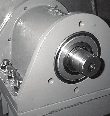

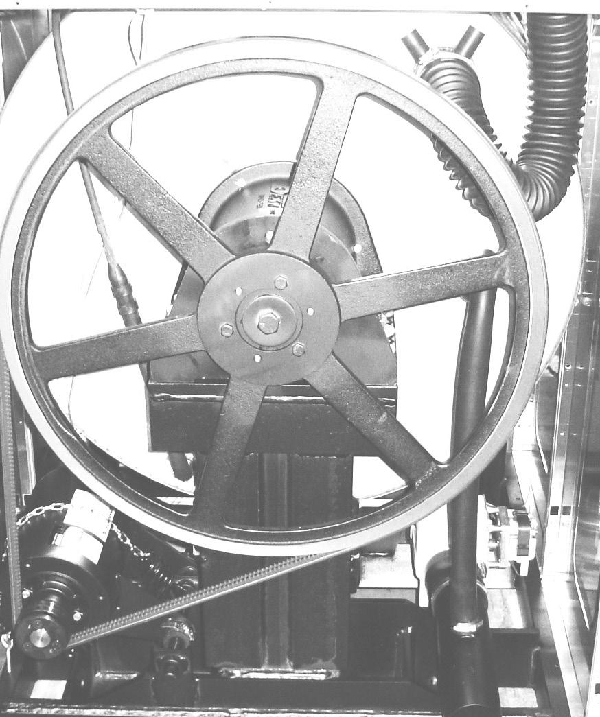
107 8 11 G ,23,24 14,15,16,17 107
108 Door Lock Assembly (All Models) Key Description All Models QTY 33 Lock Assy, Complete (#1-22) (includes #1 thru #22) Plate Assy, Door Lock Washer, Flat (SS or Brass) Actuator, Latching Switch Pawl, Locking Washer, Spring Ring, Retaining Bracket Switch Nut, Hex UNF Spring, Actuating Screw, Hx x Nut, Elastic Stop Spring, Return Pin, Guide Key Description All Models QTY 14 Ring, Retaining Washer Switch, Latching Sensing Shield, Switch Screw 4-40 x 5/ Nut, Twin Switch, Locking Sensing Actuator, Switch Locking Screw 4-40 x 1 1/ Spacer Sensor Pin, Dowel (for door cam) * Shim, Door Lock, Thin AR * Screw, Lock mtg 1/4-20 x 3/ * Lockwasher 1/4 Ext tooth
109 Gear Motor Door Lock Assembly Key Description T900 T1200 QTY * Actuator Assembly (Includes 1-10, Rod NOT included) Bracket Assy, Slide Lock Actuator Bracket Assy, Slide - Unlock Bracket Slide Lock Spacer, Plastic Arm - Door Lock Thermoactuator - Door Lock Relay 120v Spring - Extension Motor & Gear Assembly 120v Screw -Hxwshrhdslsems, 6-32 x 3/ Cross Recessed PAn Hd Tapping screw Screw Pnhdcr, UNFx Standoff-Wire * Rod, Door Lock * Harness, Door Lock/Drain, P
 8220-063-028 8220-063-028 1 *")
 9545-014-013 9545-014-013 3 9 Washer, Star 5/16")
110 Large Door & Hinge Group Key Description T900 T1200 QTY 1 Door Hinge Assembly (mounts to tub front) * Door Assembly Complete Door Ring 180 degree large hnge Door Gasket Door Glass Window * Red Wire (Door Close Switch) * Black Wire (Door Close Switch) Switch, Door Hinge Close (Plunger) Top Door Hinge Leaf Bottom Door Hinge Leaf Thrd Form Screw, Door Mtg 5/16 x 5/ Screw, Loading Door Hinge Mtg (5/16 x9/16 ss) Washer, Star 5/ Bracket Retainer support side panel * Shim Large door
 9451-181-005 9451-181-005 1 14 Pin,")
 9451-181-005 9451-181-005 1 18 Trim, Edge 9578-092-002 9578-092-002 1 5 6 8 12 13 14 11 17 18 1 7")
111 Key Description T-900 T-1200 QTY * Shaft Assembly-Loading Door (11-14) Shaft, Door Locking Cam, Locking Pin, Groove (1 1/4) Pin, Groove (3/4) Spring, Lock Cam Handle, Door Pin, Door Handle (groove) Trim, Edge
112 Key Description T900 T1200 QTY 1 Channel Assembly, Rear * Screw, #10B x 1/ * Clip, Spring Mounting Plate Water Valves Nut-Elastic stop, # Valve, Water Inlet (dual outlet) (see Water Inlet Valve Breakdown for individual parts) Screw, Valve Mtg Plate-Cover, Valves Screw, #10B x 1/ Valve, Water Inlet (Single outlet) (see Water Inlet Valve Breakdown for individual parts) Water Inlet & Rear Channel * Screw, M4x0 7 x 8mm * Wire-Assy, Jumper, Yellow Shield over Water Valves Plastic Push Clip Vacuum Breaker Fill Cap, (Red) * Bracket, Vacuum Breaker Screw, #10B x 1/ * Clamp, Hose to Vacume Braker * Hose, Vacuum Breaker to Tub * Clamp, Tub End * Hose, overflow Suds * Clamp, Hose-Spring (overflow to tub back) Plate Assembly, Drive Mounting Nut-#10-32UNF, 2B VFD Delta E drive volt * Wire assy Brown, * Wire assy Red, * Key Pad-Display Delta E Drive * Cable-Data, Communication Bushing, 7/ Plug, 7/ Bracket, Terminal-Mounting Screw, #10B x 1/ Label-Warning Strip-Terminal Marker Terminal Block Screw-Phillips, 6ABx3/ Harness-Power, Terminal Block Bushing, Terminal Lug, Solderless Lock-Washer, 1/ Screw, #10-32 TTX 1/2 GRN
 9483-004-003 9483-004-003 2 31 Screw-#10Bx1/2 9545-008-026 9545-008-026 4 32 Wire Assy, Jumper")

113 , Key Description T900 T1200 QTY 30 Braking resistors (200 ohm) Screw-#10Bx1/ Wire Assy, Jumper Screw, #6-32x5/ Nut, # * Cover Controls * Screw-#10Bx1/ * Label-Warning, Notice
114
115 10 2, , 4 9 2, , 5, 7 6, 8 Key Description T900 T Hose-water,20 1/2 I.D Hose-water,23 1/2 I.D Hose-water,29 1/2 I.D Hose-water,18 1/2 I.D Hose-water,31 1/2 I.D Hose-water,43 1/2 I.D Hose-water,40 1/2 I.D Hose-water,37 1/2 I.D Hose-water,19 7/8 I.D Hose-water,25 7/8 I.D Fill Cap, (Red) Fitting-Cross, 1/2 1 1 * Clamp 1 SS * Clamp 1 1/4 SS 4 115

116 Water Inlet Valve Breakdown Part # by Model 1 Key Description T900 T1200 QTY * Valve, Water Inlet (includes 1 thru 6) - Invensys Screen, Inlet end of valve Coil Assy., 120 V Invensys Diaphragm Invensys (EPDM) Diaphragm Invensys (Viton) Diaphragm Invensys (EPDM NSF) Guide, Solenoid Invensys Armature Invensys Spring, Armature Invensys * Wiring Harness Optional Water Valve 10 Key Description T900 T1200 QTY * Dual Coil Water Valve Mueller Valve Water Body Complete(no coil) Diaphragm Mueller Filter Mueller Coil Mueller Diaphragm Assembly Mueller Includes
 9379-194-002 1 2 Diaphragm Mueller 9118-055-001 1 3 Filter Mueller 9183-046-001 1 4 Coil Mueller 9089-051-001")
117 3 4 2 Key Description T1200 QTY * Single Coil Water Valve Mueller Valve Water Body Complete (no coil) Diaphragm Mueller Filter Mueller Coil Mueller
118 Drain Valve Group Part # by Model Key Description Part Number Qty 1 Valve, Drain (includes #2 thru # Body, Valve (w/ball) Motor & Gear Train (complete) Plate, Motor Mtg Screw Spring, Drive Screw Screw Seal, V Packer Washer Pin, Main Drive * Plate (spacers needed for replacement motor mtg. plate) Kit - Seal Replacement , 10,
119 Notes 119
120 Chassis and Drain Part # by Model Key Description T-900 T-1200 QTY 1 Base Assy,Frame Outer Tub Assy * Tub & Cylinder Assy Tub Front * Gasket, Tub Front Ring Assy, Tub Mtg-Front Clamp Bolt, Top Front Ring 3/8-16 x Nut WCAD 3/ Bolt, 1/2-13 x 2 (Tub Mounting to Frame) Nut, Wizloc 1/2 x Washer, Flat 1/ Hose, Tub to Drain Valve Clamp, Hose (Tub to Drain Valve) Valve, Drain * Screw, Valve to Base 1/4ABx3/ * Washer, Flat 1/ Hose, Drain Valve to Tube * Clamp, Hose (Drain Valve to Tube Tube Assy, Drain Clamp, Hose (Tube to Frame Bracket) * Bracket, Drain Tube 1 * Screw Tube (Bracket to Base 1/4Bx3/4) Hose, Overflow Tub To Drain Tube * Clamp, Hose * Tube, Suds overflow * Clamp, Hose Hose, Pressure switch Clamp, Hose


121 , , 8, , , , 6 121
122 Key Description T900 T1200 QTY 1 Trough Assy,Controls volt (all parts below #2-#43 & trough) * Trough only * Screw, Trough Sides * Lockwasher Exttooth # Spreader-Chanel, Trough * Screw, Mtg #8Bx1/ Transformer, Control (Secondary Voltage to 115 volts) * Screw, Mtg #8Bx1/ * Lockwasher Screw GRN. #10-32x 1/ Lockwasher # Lug, Grounding PCB assembly Relay Main * Support, Edge Holding * Harness, P17 Drain/Therm/Sol * Harness P19/Water Valve * Harness P8/P * Harness P20/P * Bushing, Wire 7/ * Standoff Twistlock Terminal Block Assy, POWER * Screw, Mtg 8Bx3/ Switch, Pressure * Screw, Mtg #8Bx1/ * Harness P5/Pressure Transformer, (Step Down) 120/24VAC 50/60hz * Screw, Transformer Mtg #10Bx1/ * Lockwasher #10 exttooth Fuseholder * Fuse 1.5 amp * Fuse 2.5 amp Label Fuse 1.5 amp Rear Label Fuse 2.5 amp Rear Angle Support Trough * Screw, Trough Bracket Chanel-Support, Trough * Screw, Mtg #8Bx1/ Chanel * Screw, Mtg #8Bx1/ * Kit-Pressure Sensor, Electronic Kit-Repaacement, Pressure Sensor (only) * Support-PCB, 3/8, Edge Holding Transformer-120/18VAC, 5 VA Screw, 8B x 1/ * Wire Assy BLK/BLU * Wire Assy RED/BLU


123 Electrical Components - Top Compartment , 5,
124 Control Panel Part # by Model Key Description T900 T1200 QTY 1 Panel Control Assembly(panel only) * Screw, to Side Panels 5/16, Hxwshrhdundct #10Bx 1/ Plate-Latch, Top Nut, # Locator Panel Screw FillHDCR 10Bx1/2 Guide Spacer Pushbutton (Micro) Pushbutton Control (coin)[blue] Pushbutton Control (coin)[black] Retainer Pushbutton (Micro) Nut Hexelasticstop # Spacer Plastic #6x9/ PCB assembly Control /Display STOP Nut Elasticstop # Nut-Hexkeps, # Harness LEDPCB * Harness Doorlock, Switches Spacer Plastic #6x9/ PCB assembly Mode lights Nut Hexkeps # Accecptor-Coin, Optical Retainer, Coin Accecptor Screws, Torx, T-10, 4Bx5/8ss Switch Assembly Emergency Stop (includes wire harness) Spacer Plastic #8x5/16 E-Stop Plate to mount e-stop button Nuts-Hexkeps, # Plastic Shield over main PCB Nuts-Hexkeps, # Nameplate,Control Panel (Blue) Nameplate,Control Panel (Black) Motor Ass y, Door Locking (see Door Lock Group for parts breakdown) Nuts-Hexkeps, # * Battery Cable, USB Screw-Torx T10, #4-40x3/8ss Nut, Spring


125 ,

 8502-759-001 8502-759-001 1 3 Label Dispenser (Blue) 8502-756-002 8502-756-002 1 3 Label Dispenser (Black) 8502-756-001 8502-756-001 1 * Booklet Owners 8514-229-001 8514-230-001 1")
126 Labels and Diagrams Key Description T-900 T-1200 QTY * Wiring Diagram and Schematic, Coin * Transient Voltage Surge Suppressor Infomational * Label High Voltage Warning * Label Fusing & Installation * Label Quality Label Warning Door Opening (Blue) Label Warning Door Opening (Black) Label Warning Risk of Injury (Blue) Label Warning Risk of Injury (Black) Label Dispenser (Blue) Label Dispenser (Black) * Booklet Owners
127 Section 9: Coin Handling Parts: Wiring Diagrams & Schematics & maintenance Procedures 127


128 Optical Coin Acceptor Starting after serial# Key Description T900 T Optical Coin Acceptor Replacement Optical Sensor * Screw, Highth Bar, 3mm QTY
 9021-028-001 9021-028-001 1 2 Harness for Electronic Coin Acceptor 9627-845-001 9627-845-001 1 3 Transformer")
129 Kit - Electronic Acceptor Conversion for WCAD (USA and Canada) Key Description T900 T1200 QTY KIT - Electronic Acceptor Conversion for WCAD (USA and Canada) Contact the Dexter Factory for Other Countries Electronic Coin Acceptor (USA and Canada) Harness for Electronic Coin Acceptor Transformer 120/18VAC * Wire Assembly - Blue * Wire Assembly - Orange/White Coin Chute for Electronic Drop * Nut - Hex Elastic Stop * Screw, Torx * Screw, Hex * Label, Informative * Label, Warning * Instructions, Installation Coin Chute for Electronic Drop

130 Electronic Acceptor Coin Drop Setting the electronic coin acceptor switches Some washer models come equipped with an electronic coin acceptor. Follow the instructions below for setting the switches for the desired country and currencies. 1. The electronic coin acceptor has switch settings depending on the coins and country. See the table below for available values of the left and right coin inputs for the available countries. WARNING: turn power off before and leave power off when changing the switches of the electronic coin acceptor. 2. Turn power back on and test coins to ensure proper operation. Dip Switches 130
131 131
132 132
133 133

")


134 Maintenance Instructions Electronic Acceptor Cleaning the electronic coin selector The EMP 500 v5 is an extraordinarily robust coin selector and operates relatively maintenance free. However, it should be cleaned at regular intervals (minimum once a year) especially if it is operating in an environment with high levels of dust, smoke or nicotine. The cleaning intervals are of course dependent on the level of air borne contaminants. Clean the coin path with soft brush and wipe the exposed surfaces. Use an alcohol moistened cloth. If you find solid residues stuck to the coin rail remove it with an alcohol moistened cloth. Optical sensors may be cleaned with a soft brush very carefully with an air spray duster. Location of the optical sensor within coin outlet. 134
135 Notes 135
136 T900 Non-Express Vended Schematic 136
137 T900 Non-Express Vended Diagram 137
138 T1200 Non-Express Vended Schematic 138
139 T1200 Non-Express Vended Diagram 139
140 Notes 140
141 Section :10 Parts 50Hz Models: Parts in this section used only in these models. All other parts are same as standard 60 Hz pages. Wiring Diagrams & Schematics 141

 9118-049-001 9118-049-001 2 Diaphragm Invensys (Viton) 9118-049-002 9118-049-002 2 Water")
142 Transformer, Electrical -39 models WC0900-XA39ECX 230 volts 50hz. Single Phase WC01200-XA39ECX 230 volts 50hz Single Phase Key Component T900 T1200 QTY 1 Circuit Breaker * Instructions, Transformer Connect Controls Transformer, 200/250-24V 50Hz Water Valve Diaphragm Invensys (EPDM) Diaphragm Invensys (Viton) Water Valve Single Diaphragm Mueller Wiring Label, Schematic & Diagram Wiring Harness, Power Terminal Block Wiring Harness Main,
")


 9538-149-001 1 12 Kit - Seal Replacement 9732-327-001 1 2 4 12")
143 Drain Valve Group 50 HZ Key Description Part Number Qty 1 Valve, Drain (includes #2 thru # Body, Valve (w/ball) Motor & Gear Train (complete) Plate, Motor Mtg Screw Spring, Drive Screw Screw Seal, V Packer Washer Pin, Main Drive * Plate (spacers needed for replacement motor mtg. plate) Kit - Seal Replacement , 10,
C-Series Vended Washers T300, T400, T600 (100G) & T350, T450 (Express Washers 200G)
 & T350, T450 (Express Washers 200G)") C-Series Vended Washers T300, T400, T600 (100G) & T350, T450 (Express Washers 200G) Parts & Service Manual Serial # W1.15244.001 8533-080-001 12/15 Equipment Safety Warnings Symbols and Terminology Used
C-Series Vended Washers T300, T400, T600 (100G) & T350, T450 (Express Washers 200G) Parts & Service Manual Serial # W1.15244.001 8533-080-001 12/15 Equipment Safety Warnings Symbols and Terminology Used
COMMERCIAL WASHERS MODELS T-300/350/400/450/600/650/750/900/950/1200/1450 VENDED C-SERIES CONTROL
 COMMERCIAL WASHERS MODELS T-300/350/400/450/600/650/750/900/950/1200/1450 VENDED C-SERIES CONTROL OPERATOR S MANUAL INSTALLATION & OPERATION INSTRUCTIONS Please read this information and retain for reference.
COMMERCIAL WASHER MODEL T-600 VENDED C-SERIES CONTROL 50 Hz
 COMMERCIAL WASHER MODEL T-600 VENDED C-SERIES CONTROL 50 Hz OPERATOR S MANUAL INSTALLATION & OPERATION INSTRUCTIONS Please read this information and retain for reference. WARNING - THIS WASHER IS EQUIPPED
OPERATOR S MANUAL INSTALLATION & OPERATION INSTRUCTIONS. Please read this information and retain for reference.
 COMMERCIAL WASHER MODEL T-650 VENDED C-SERIES CONTROL Original Instructions For GB & IE OPERATOR S MANUAL INSTALLATION & OPERATION INSTRUCTIONS Please read this information and retain for reference. The
COMMERCIAL WASHER MODEL T-600 VENDED C-SERIES CONTROL
 COMMERCIAL WASHER MODEL T-600 VENDED C-SERIES CONTROL OPERATOR S MANUAL INSTALLATION & OPERATION INSTRUCTIONS Please read this information and retain for reference. WARNING - THIS WASHER IS EQUIPPED WITH
MODEL T900/950 60LB CAPACITY COMPUTER CONTROL COIN WASHER
 P/N 8514-183-001B MODEL T900/950 60LB CAPACITY COMPUTER CONTROL COIN WASHER DEXTER LAUNDRY, INC. OWNER'S BOOKLET INSTALLATION & OPERATION INSTRUCTIONS Please read this information and retain for reference.
DC30X2 Models / 24VAC Control 30 Pound Stacked Commercial Dryer. Service and Parts Manual. Starting Serial # D /16
 DC30X2 Models / 24VAC Control 30 Pound Stacked Commercial Dryer Service and Parts Manual Starting Serial # D1.15181.001 8533-090-001 5/16 Equipment Safety Warnings Symbols and Terminology Used in this
WC Series Vended Washers Troubleshooting, and Fault Codes
 WC Series Vended Washers Troubleshooting, and Codes 1 Common Troubleshooting s Symptom Probable Cause Suggested Remedy 2 Machine does not start Machine will not accept and count coins Door does not lock
WCAD-Series Vended Washers Troubleshooting And Fault Codes
 WCAD-Series Vended Washers Troubleshooting And Fault Codes Part # 8533-066-001 5/11 1 Common Troubleshooting Solutions Symptom Probable Cause Suggested Remedy 2 Machine does not start Machine will not
INDUSTRIAL WASHER MODEL T-450 SWD EXPRESS ON-PREMISE V-SERIES CONTROL
 INDUSTRIAL WASHER MODEL T-450 SWD EXPRESS ON-PREMISE V-SERIES CONTROL OPERATOR S MANUAL INSTALLATION & OPERATION INSTRUCTIONS Please read this information and retain for reference. WARNING - THIS WASHER
MODEL T LB CAPACITY COMPUTER CONTROL OPL WASHER
 P/N 8514-220-001PR MODEL T1450 90 LB CAPACITY COMPUTER CONTROL OPL WASHER DEXTER LAUNDRY, INC. OWNER'S BOOKLET INSTALLATION & OPERATION INSTRUCTIONS TABLE OF CONTENTS Page # Safety Warnings 2 Maintenance
WCVD-Series OPL Washers Troubleshooting And Fault Codes. Starting serial number ****** (09/13)
") WCVD-Series OPL Washers Troubleshooting And Fault Codes Starting serial number ****** 8533-074-001 (09/13) Common Troubleshooting Solutions Symptom Probable Cause Suggested Remedy Machine does not start
WCVD-Series OPL Washers Troubleshooting And Fault Codes Starting serial number ****** 8533-074-001 (09/13) Common Troubleshooting Solutions Symptom Probable Cause Suggested Remedy Machine does not start
INDUSTRIAL WASHER MODEL T-1450 ON-PREMISE N-SERIES CONTROL
 INDUSTRIAL WASHER MODEL T-1450 ON-PREMISE N-SERIES CONTROL OPERATOR S MANUAL INSTALLATION & OPERATION INSTRUCTIONS Please read this information and retain for reference. WARNING: THIS WASHER IS EQUIPPED
V-SERIES CONTROL 50Hz
 INDUSTRIAL WASHER MODEL T-400 ON-PREMISE V-SERIES CONTROL 50Hz Original Instructions For GB & IE OPERATOR S MANUAL INSTALLATION & OPERATION INSTRUCTIONS Please read this information and retain for reference.
DC50X2 Models 50 Pound Stacked Commercial Dryer. Troubleshooting,Fault Codes, and Schematics. Starting serial number Part # /13
 DC50X2 Models 50 Pound Stacked Commercial Dryer Troubleshooting,Fault Codes, and Schematics Starting serial number Trouble Shooting Electronic Control Diagnostic s The electronic control has 6 diagnostic
Models Product Information. Important Safety Instructions REV
 Models- 29060-29063 Page 2 - Page 3 - Page 4 - Page 5 - Page 6 7 Page 7-10 Page 10 Page 11 Page 11-12 Page 13-17 Page 18-21 Product Information Specifications Important Safety Instructions Product Dimensions
D-TECT 2 IP. GJD230 IP Motion Detector
 D-TECT 2 IP GJD230 IP Motion Detector PACKAGE CONTENTS 1 x D-TECT 2 IP 1 x Drilling template for fixing holes 3 x 31.75mm wall plugs 3 x 31.75mm screws 2 x Spare sliding curtains 2 x Tamper feet 1 x Tamper
Viking Installation Guide
 Viking Installation Guide Viking Range Corporation 111 Front Street Greenwood, Mississippi 38930 USA (662) 455-1200 For product information, call 1-888-VIKING1 (845-4641) or visit the Viking Web site at
Fast Track Troubleshooting
 Fast Track Troubleshooting Publication # rswf241 Revision Date 12/20/2011 Model: WF241ANW IMPORTANT SAFETY NOTICE For Technicians Only This service data sheet is intended for use by persons having electrical,
D-TECT 3 IP. GJD260 IP Motion Detector
 D-TECT 3 IP GJD260 IP Motion Detector PACKAGE CONTENTS 1 x D-TECT 3 IP 1 x Drilling template for fixing holes 3 x 31.75mm wall plugs 3 x 31.75mm screws 2 x Spare sliding curtains 2 x Tamper feet 1 x Tamper
Operating manual. Wascator FOM71 CLS
 Operating manual Wascator FOM71 CLS Operating manual in original language 438 9200-91/EN 2010.05.03 Register now And be able to join the Wascator FOM 71 CLS web site where you can find: General information
Fast Track Troubleshooting
 Fast Track Troubleshooting Model: WF419AA*/XAA BOM Name: WF419AAW/XAA WF419AAU/XAA IMPORTANT SAFETY NOTICE For Technicians Only This service data sheet is intended for use by persons having electrical,
INSTALLATION INSTRUCTIONS INSTRUCTIONS D INSTALLATION INSTRUCCIONES DE INSTALACIÓN
 EN FRONT LOAD DRYER FR SÉCHEUSE Á CHARGEMENT FRONTAL ES SECADORA DE CARGA FRONTAL INSTALLATION INSTRUCTIONS INSTRUCTIONS D INSTALLATION INSTRUCCIONES DE INSTALACIÓN 2 IMPORTANT SAFETY INSTRUCTIONS For
ARGO (Technical Support) 2201 Dwyer Avenue Utica, NY (Corporate Sales) 85 Middle Road
 2201 Dwyer Avenue Utica, NY (Corporate Sales) 85 Middle Road") ARGO (Technical Support) 2201 Dwyer Avenue Utica, NY 13501 (Corporate Sales) 85 Middle Road An ISO 9001-2000 Certified Company Dunkirk, NY 14048 www.argoindustries.com P/N 240005498A, Rev. 1.5 [02/07]
ARGO (Technical Support) 2201 Dwyer Avenue Utica, NY 13501 (Corporate Sales) 85 Middle Road An ISO 9001-2000 Certified Company Dunkirk, NY 14048 www.argoindustries.com P/N 240005498A, Rev. 1.5 [02/07]
Operating, Installation and Service Manual W3400H, CLC 41 Clarus Control
 Operating, Installation and Service Manual W3400H, CLC 41 Clarus Control 438 9202-01 05.26 Washer extractor, drum volume 400 litres 3 Contents Machine operation... 7 General description... 7 Automatic
Fast Track Troubleshooting
 Fast Track Troubleshooting Model: WF330ANW/XAA Please Note: There are two Versions of this model, when ordering parts please verify the version you are servicing. IMPORTANT SAFETY NOTICE For Technicians
CAUTION All safety information must be followed as provided in this Technical Sheet and in Service Manual RS
 Domestic Washer Technical Information 120 V, 60 Hz Models SAV2555AW* Due to possibility of personal injury or property damage, always contact an authorized technician for servicing or repair of this unit.
PHASE COIN USER S MANUAL
 PHASE 7.3.2 COIN USER S MANUAL American Dryer Corporation 88 Currant Road Fall River, MA 02720-4781 Telephone: (508) 678-9000 / Fax: (508) 678-9447 E-mail: techsupport@amdry.com www.amdry.com ADC Part
Water Boilers ME10EN, ME15EN. Table of Contents
 Water Boilers ME10EN, ME15EN Operator Manual Model ME15EN Model ME10EN Safety Information...2 Rough-In Drawing...3 Installation...4 Priming...5 Cleaning...5 Table of Contents Adjustments...6 Maintenance...7
Fast Track Troubleshooting
 Fast Track Troubleshooting Model: WF409ANW/XAA Please Note: There are 2 versions of this model. Verify version # BEFORE ordering service parts. IMPORTANT SAFETY NOTICE For Technicians Only This service
! WARNING To avoid risk of electrical shock, personal injury or death; disconnect power to washer before servicing, unless testing requires power.
 24 Front Load Washer Technical Information MAH2400A* Due to possibility of personal injury or property damage, always contact an authorized technician for servicing or repair of this unit. Refer to Service
PHASE DMC USER S MANUAL
 PHASE 7.4.2 DMC USER S MANUAL American Dryer Corporation 88 Currant Road, Fall River MA 02720-4781 USA Telephone: +1 (269) 923-3000 / Fax: +1 (508) 678-9447 e-mail: mdl-service@whirlpool.com / www.adclaundry.com
Fast Track Troubleshooting
 Fast Track Troubleshooting Model: WF210ANW/XAA Please Note: There are Serial # changes on this model, verify you are ordering the correct parts for the Serial # you are servicing by reviewing Bulletins.
Installation Instructions
 Electric Heaters 5 --- 20 kw SMALL PACKAGED PRODUCTS (SPP) Accessory Electric Heaters For 13 SEER, R---410A, Z Chassis Installation Instructions NOTE: Read the entire instruction manual before starting
MASTER JOCKEY PUMP CONTROLLER. Model JPCE INSTRUCTION MANUAL. C 2018 Master Control Systems, Inc
 MASTER JOCKEY PUMP CONTROLLER Model JPCE INSTRUCTION MANUAL C 2018 Master Control Systems, Inc TABLE OF CONTENTS Important Safety Information. Page 3 General Description and Installation.. Page 4 Model
CONTROL PANEL INTERFACE ACTIVATE THE GENERATOR DISPLAY INTERFACE MENUS. Control Panel USING THE AUTO/OFF/MANUAL SWITCH
 CONTROL PANEL INTERFACE USING THE AUTO/OFF/MANUAL SWITCH With the switch set to AUTO, the engine may crank and start at any time without warning. Such automatic starting occurs when utility power source
TECHNICAL INFORMATION Touchtronic Clothes Dryers
 TECHNICAL INFORMATION Touchtronic Clothes Dryers Includes: T1302, T1303, T1322, T1329ci T1403 & T1405 2004 Miele This page intentionally left blank. Table of Contents GENERAL INFORMATION A. Warning and
Attached is Supplement three for service manual We suggest you file this with your Manual for reference.
 INTRODUCTION Attached is Supplement three for service manual 16008203. We suggest you file this with your 16008203 Manual for reference. Models covered in this manual: MAH21PD MAH21PN MAH21PR MAH21PS CONTENTS
Operator s Manual READY RACK EXTRACTOR. Installation/Operation/Maintenance/Parts DIMENSIONS OF THE WASHER: HEIGHT (AT BACK): 42
: 42") READY RACK EXTRACTOR DIMENSIONS OF THE WASHER: HEIGHT (AT BACK): 42 HEIGHT (W/ LID RAISED): 56 WIDTH: 27 DEPTH: 26 DEPTH (W/ REAR HOSE): 30 WEIGHT: 190 lbs. SHIP WEIGHT: 255 lbs. Operator s Manual Installation/Operation/Maintenance/Parts
READY RACK EXTRACTOR DIMENSIONS OF THE WASHER: HEIGHT (AT BACK): 42 HEIGHT (W/ LID RAISED): 56 WIDTH: 27 DEPTH: 26 DEPTH (W/ REAR HOSE): 30 WEIGHT: 190 lbs. SHIP WEIGHT: 255 lbs. Operator s Manual Installation/Operation/Maintenance/Parts
Installation Instructions
 Electric Heaters 5 --- 20 kw SMALL PACKAGED PRODUCTS (SPP) Accessory Electric Heaters For 13 SEER, R---410A Manufactured Home Installation Instructions NOTE: The Dual Point Kit can only be installed on
The Classeq under counter range
 Installation & Operators Manual The under counter range Part number 902.0011 Revision C Effective date January 2010 Language English Glasswashers Eco 1 Eco 2 Eco 3 Duo 2 Duo 3 Dishwasher Hydro 500 Hydro
ULTRA LOW TEMPERATURE FREEZER. User Manual
 ULTRA LOW TEMPERATURE FREEZER User Manual Note:Kaltis reserves the right to modify any parts of this manual without prior notice. 1. No part of this manual may be reproduced in any form, or translated
INSTALLATION MANUAL ICE/BEVERAGE DISPENSER MODEL: ENDURO-200/250
 INSTALLATION MANUAL ICE/BEVERAGE DISPENSER MODEL: ENDURO-200/250 Release Date: March 24, 2004 Publication Number: 92181INS Revision Date: April 07, 2014 Revision: G Visit the Cornelius web site at www.cornelius.com
PROAIR Air Conditioner. CR23 Model INSTRUCTION MANUAL nvent Rev. D P/N
 PROAIR Air Conditioner CR23 Model INSTRUCTION MANUAL Rev. D P/N 89112522 TABLE OF CONTENTS Warranty and Return Policy...2 RECEIVING THE AIR CONDITIONER...3 HANDLING AND TESTING THE AIR CONDITIONER...3
9420* & * Coin Operated Models C* Commercial Models. Product Information. Important Safety Instructions
 Models - 9420* & 9420-1* Coin Operated Models 9420-1C* Commercial Models Page 2 Page 3 Page 4 Page 5-7 Page 8-12 Page 12-13 Page 14 Page 14-15 Page 16-21 Page 22-24 Product Information Specifications Important
PROAIR Air Conditioner. CR29 Model INSTRUCTION MANUAL nvent Rev. I P/N
 PROAIR Air Conditioner CR29 Model INSTRUCTION MANUAL Rev. I P/N 89104461 TABLE OF CONTENTS Warranty and Return Policy...2 RECEIVING THE AIR CONDITIONER...3 HANDLING AND TESTING THE AIR CONDITIONER...3
Installation and Operation Manual CLEARVIEW DAY COVER CAUTION: To view a video scan the QR code above
 Installation and Operation Manual CLEARVIEW DAY COVER To view a video scan the QR code above CAUTION: Please read this manual completely before attempting to install, operate or service this equipment
Hot Water Dispensers HWD2, HWD3, HWD5. Table of Contents
 Hot Water Dispensers HWD2, HWD3, HWD5 Operator Manual Activate your warranty now at http://gmcw.com/warranty-registration Model HWD2 Safety Information...2 Rough-In Drawing...3 Specifications...4 Installation...4
Model: PC600. Batch: PR3496. POWER:1000W AC V, 50/60Hz For your safety, always read the instruction book carefully before using.
 Model: PC600 Batch: PR3496 POWER:1000W AC220-240V, 50/60Hz For your safety, always read the instruction book carefully before using. Introduction-----------------------------------------------------------------------------------------------
Installation. 324 Series Built-In Dishwashers U L. Viking Range, LLC 111 Front Street Greenwood, Mississippi USA (662)
") Installation Viking Range, LLC Front Street Greenwood, Mississippi 890 USA (66) 455-00 For product information, call -888-845-464 or visit the Viking Website at vikingrange.com U L C U L 4 Series Built-In
Installation Viking Range, LLC Front Street Greenwood, Mississippi 890 USA (66) 455-00 For product information, call -888-845-464 or visit the Viking Website at vikingrange.com U L C U L 4 Series Built-In
INSTALLATION MANUAL AND OPERATING INSTRUCTIONS
 AMB4/AMB8 MULTIPLE BOILER SEQUENCERS INSTALLATION MANUAL AND OPERATING INSTRUCTIONS ARGO (Technical Support) 2201 Dwyer Avenue Utica, NY 13501 (Corporate Sales) 85 Middle Road An ISO 9001-2000 Certified
Homestyle Frontload Washers
 Homestyle Frontload Washers Service Refer to Page 2 for Model Numbers FLW1515C www.comlaundry.com Part No. 801728R3 May 2007 Table of Contents Model Identification...2 Section 1 Safety Information Locating
T-SERIES Air Conditioner. T29 Model INSTRUCTION MANUAL nvent Rev. I P/N
 T-SERIES Air Conditioner T29 Model INSTRUCTION MANUAL Rev. I P/N 89104464 TABLE OF CONTENTS Warranty and Return Policy...2 IMPORTANT NOTICE...2 RECEIVING THE AIR CONDITIONER...3 HANDLING AND TESTING THE
Installation Instructions
 50ZPB, C, 50ZHB, C, PA3Z ---A, PH3Z ---A, PA4Z, PH4Z, PAJ4,PHJ4,WJA4,WJH4 SMALL PACKAGED PRODUCTS (SPP) Accessory Electric Heaters 5---20 kw For 14 SEER, R---410A Manufactured Home Installation Instructions
User s Manual UPRIGHT FREEZER WHS-507FWEW1 / WHS-507FWESS1 WHS-625FWEW1 / WHS-625FWESS1 WHS-772FWEW1 / WHS-772FWESS1
 User s Manual UPRIGHT FREEZER WHS-507FWEW1 / WHS-507FWESS1 WHS-625FWEW1 / WHS-625FWESS1 WHS-772FWEW1 / WHS-772FWESS1 Contents Introductions..................................................... 3 Important
Installation Instructions
 50ES--A, 50EZ--A, 50VG--A, B, 50VL--A, B, 50VR--A, 50VT--A, B 604D-- --A, 607C-- --A, B, 607E-- --A, 704D-- --A, 707C-- --A, B, 707E-- --A PA3G -- -- A, PH3G -- -- A, PA4G, PH4G PAD3, PHD3, PAD4, PHD4,
Dexter Commercial Vended Stack Washer Dryer. Dryer Troubleshooting, Fault Codes, And Schematics. Starting serial number (12/13)
") Dexter Commercial Vended Stack Washer Dryer Dryer Troubleshooting, Fault Codes, And Schematics Starting serial number 481983 8533-070-001 (12/13) Dryer Trouble Shooting Electronic Control Diagnostic Lights
Dexter Commercial Vended Stack Washer Dryer Dryer Troubleshooting, Fault Codes, And Schematics Starting serial number 481983 8533-070-001 (12/13) Dryer Trouble Shooting Electronic Control Diagnostic Lights
FOR SERVICE TECHNICIAN ONLY DO NOT REMOVE OR DESTROY WARNING
 WARNING Electrical Shock Hazard Disconnect power before servicing. Replace all parts and panels before operating. Failure to do so can result in injury or death. IMPORTANT Electric Discharge (ESD) Sensitive
FAVORIT34502VIO. EN User Manual
 FAVORIT34502VIO EN User Manual 2 www.aeg.com CONTENTS 1. SAFETY INFORMATION...3 2. SAFETY INSTRUCTIONS... 4 3. PRODUCT DESCRIPTION... 6 4. CONTROL PANEL...6 5. PROGRAMMES... 7 6. SETTINGS... 8 7. BEFORE
MASTER PRESSRE MAINTANENCE CONTROLLER. Models PMCE INSTRUCTION MANUAL. C 2018 Master Control Systems, Inc
 MASTER PRESSRE MAINTANENCE CONTROLLER Models PMCE INSTRUCTION MANUAL C 2018 Master Control Systems, Inc TABLE OF CONTENTS Important Safety Information. Page 3 General Description and Installation.. Page
T-SERIES Air Conditioner. T43 Model INSTRUCTION MANUAL nvent Rev. I P/N
 T-SERIES Air Conditioner T43 Model INSTRUCTION MANUAL Rev. I P/N 10-1008-145 TABLE OF CONTENTS Warranty and Return Policy...2 IMPORTANT NOTICE...2 RECEIVING THE AIR CONDITIONER...3 HANDLING AND TESTING
8648 Series Air/ Water/ Vacs. Product Information. Important Safety Instructions. Operating Instructions Maintenance & Troubleshooting REV
 Models - 8648 Series Air/ Water/ Vacs Page 2 Page 3 Page 4 Page 5-6 Page 7-10 Page 10-11 Page 12 Page 12-13 Page 14-17 Page 18-19 Product Information Specifications Important Safety Instructions Product
THX-DL Data Logger USER & INSTALLATION MANUAL V
 THX-DL Data Logger USER & INSTALLATION MANUAL V1.2012 www.thermomax-refrigeration.com Contents PRESENTATION Summary of Features 2 INSTALLATION Safety Precautions 4 THX Unit 4 Sensors 4 Alarm Relay 4 Power
D3000. Installation & Setup Guide
 Page 1 of 15 17483-00 Rev B s1 April 2009 Contents Description Page Safety... 3 Installation Standards 3 Specification. 3-4 Circuit Board Connection 5 Mounting Dimensions 6 Installation Procedure 6 Mechanical
Installation manual W365H, W375H, W3105H, W3130H, W3180H, W3240H, W3300H Exacta & Clarus Control
 manual W365H, W375H, W305H, W330H, W380H, W3240H, W3300H Exacta & Clarus Control 438 9200-0 06.34 Contents 3 Contents Technical data... :... 2: Transportation and unpacking... 2: Siting and floor... 3:
Washer-Extractor. Troubleshooting. Cabinet Hardmount Mechanical Timer Refer to Page 8 for Model Numbers.
 Washer-Extractor Cabinet Hardmount Mechanical Timer Refer to Page 8 for Model Numbers Troubleshooting CHM1624C www.comlaundry.com Part No. F232202R3 November 2011 Table of Contents Safety Information...3
Indicates a hazardous situation which, if not avoided, will result in death or serious injury.
 Installation Instructions If you have any questions, call 800.GE.CARES (800.432.2737) or visit our Website at: GEAppliances.com In Canada, call 1.800.561.3344 or visit www.geappliances.ca This is the safety
PROAIR Air Conditioner. CR43 Model INSTRUCTION MANUAL nvent Rev. H P/N
 PROAIR Air Conditioner CR43 Model INSTRUCTION MANUAL Rev. H P/N 10-1008-130 TABLE OF CONTENTS Warranty and Return Policy...2 RECEIVING THE AIR CONDITIONER...3 HANDLING AND TESTING THE AIR CONDITIONER...3
ModSync Sequencing System Installation & Operation Manual. For use with Fulton Steam Boilers.
 ModSync Sequencing System Installation & Operation Manual For use with Fulton Steam Boilers. Revision 3.0 8/21/2008 - 2 - Table of Contents Introduction Page 4 Features Page 4 Sequence of Operation Page
Fast Track Troubleshooting
 Fast Track Troubleshooting Model: WA5471***/XAA IMPORTANT SAFETY NOTICE For Technicians Only This service data sheet is intended for use by persons having electrical, electronic, and mechanical experience
CQUBE EVO OPERATION MANUAL EVO_OM_VKI_EN. Part No.: _06
 EVO_OM_VKI_EN Part No.: 1764212_06 CQUBE EVO OPERATION MANUAL CONTENTS GENERAL INFORMATION...3 Introduction... 3 Warnings... 3 Precautions... 4 Intended use... 4 Hazard intensity levels... 4 Facts & weight...
W71E - W101E. Manual / Handbuch. Spare parts list / Ersatzteilliste
 W71E - W101E Manual / Handbuch Spare parts list / Ersatzteilliste Equipment Imp.-Exp. GmbH Zitterpappelweg 9 D - 22391 Hamburg Tel.: + 49 40 60009468-0 Fax: + 49 40 536 75 01 E - M a i l : i n f o @ w
Spa Touch Control Panel with 2000, 2100 controllers. (Spa Owner s Manual insert)
") Spa Touch Control Panel with 2000, 2100 controllers (Spa Owner s Manual insert) P.N. 7876B February 11, 2015 For Spas equipped with BP2000, BP2100 controllers and Spa Touch panel. Spa Touch Control Panel
Spa Touch Control Panel with 2000, 2100 controllers (Spa Owner s Manual insert) P.N. 7876B February 11, 2015 For Spas equipped with BP2000, BP2100 controllers and Spa Touch panel. Spa Touch Control Panel
FAVORIT 34502VI0. EN User manual
 FAVORIT 34502VI0 EN User manual 2 www.aeg.com CONTENTS 1. SAFETY INSTRUCTIONS...................................................... 3 2. PRODUCT DESCRIPTION.....................................................
W71E - W101E. Manual / Handbuch. Spare parts list / Ersatzteilliste
 W71E - W101E Manual / Handbuch Spare parts list / Ersatzteilliste Equipment Imp.-Exp. GmbH Zitterpappelweg 9 D - 22391 Hamburg Tel.: + 49 40 60009468-0 Fax: + 49 40 536 75 01 E - M a i l : i n f o @ w
QuadraTouch Pro Software Manual Dryer Control System
 QuadraTouch Pro Software Manual Dryer Control System Software is constantly changing. Make sure you are up to date with Sukup s newest software. New software and manuals are available for download at:
DRAFT INSTALLATION INSTRUCTIONS. Solid-State Series !! NOTE!! Covers the following models: Refer to INSERT for additional information
 INSTALLATION INSTRUCTIONS Solid-State Series!! NOTE!! Covers the following models: " CS6100 - CS7100 " CS6200 - CS9200 " CS6220 - CS9220 " CS6230 - CS9230 " CS6500 - CS7500 " CS6330 - CS9300 " CS9400 -
! CAUTION. All safety information must be followed as provided in Service Manual ! WARNING
 Front Load Washer Technical Information MAH6500* Due to possibility of personal injury or property damage, always contact an authorized technician for servicing or repair of this unit. Refer to Service
WASHING MACHINE SERVICE MANUAL CAUTION READ THIS MANUAL CAREFULLY TO DIAGNOSE PROBLEMS CORRECTLY BEFORE SERVICING THE UNIT.
 WASHING MACHINE SERVICE MANUAL CAUTION READ THIS MANUAL CAREFULLY TO DIAGSE PROBLEMS CORRECTLY BEFORE SERVICING THE UNIT. MODEL : WM2240C* Jul. 2010 PRINTED IN KOREA P/No. : MFL30599179 CONTENTS 1.SPECIFICATIONS...
Installation Instructions
 50ES---A, 50EZ---A, 50VL---A, 50VG---A, 50VR---A, 50VT---A, 604D--- ---A, 607C--- ---A, 607E,--- ---A, 704D--- ---A, 707C--- ---A, 707E--- ---A PA3G --- --- A, PH3G --- --- A SMALL PACKAGED PRODUCTS Electric
Installation Instructions
 Installation Instructions for Topload Washers Original Instructions Keep These Instructions for Future Reference. (If this machine changes ownership, this manual must accompany machine.) www.speedqueen.com
Installation Instructions
 Instructions for Frontload Washers Original Instructions Keep These Instructions for Future Reference. (If this machine changes ownership, this manual must accompany machine.) www.alliancelaundry.com Part
Marco Beverage Systems Ltd.
 Marco Beverage Systems Ltd. INSTRUCTIONS FOR MODELS ECOSMART PB10, ECOSMART PB10 Hi Deck ECOSMART T10 (P/N: 1000677#, 1000678#, 1000674#) Water pressure : 5-50 psi (min.-max.)35-345 kpa (min.-max.) Marco
Installation Instructions
 EHNA Electric Heaters 5-20kW For 60 Hz Small Packaged Products MODELS: PAD3, PHD3, PAD4, PHD4, PAD5, PHD5, WPA3, WPH3 Installation Instructions NOTE: Read the entire instruction manual before starting
Service Test Mode
 Service Test Mode The washer control has a service test mode that can be utilized by the service technician in order to test critical components and to access error codes. This test mode will help the
Read this owner's manual thoroughly before operating the appliance and retain it for future reference. TYPE : PORTABLE AIR CONDITIONER
 ENGLISH ESPAÑOL Read this owner's manual thoroughly before operating the appliance and retain it for future reference. TYPE : PORTABLE AIR CONDITIONER MODEL : LP0817WSR LP1017WSR LP1217GSR LP1417SHR LP1417GSR
IntelliDoX Operator Manual
 IntelliDoX Operator Manual OPERATOR MANUAL TABLE OF CONTENTS Table of Contents Table of Contents...1 About this Publication...3 Important Safety Information: Read First...4 Getting Started...5 About the
WARNING. Electrical Shock Hazard FOR SERVICE TECHNICIAN ONLY DO NOT REMOVE OR DESTROY L WASHER. Pub # /18/10 GE
 L WASHER WARNING Electrical Shock Hazard Disconnect power before servicing. Replace all parts and panels before operating. Failure to do so can result in injury or death. IMPORTANT Electric Discharge (ESD)
Spa Touch Control Panel with BP2100, BP6013 spa controllers. (Spa Owner s Manual insert)
") Spa Touch Control Panel with BP2100, BP6013 spa controllers. (Spa Owner s Manual insert) P.N. 7876C (export) February 12, 2015 For Spas equipped with BP2100, BP6013 controllers and Spa Touch panel. Spa
Spa Touch Control Panel with BP2100, BP6013 spa controllers. (Spa Owner s Manual insert) P.N. 7876C (export) February 12, 2015 For Spas equipped with BP2100, BP6013 controllers and Spa Touch panel. Spa
D3000. Installation and Operating Manual SAFETY D3000 SPECIFICATIONS PRODUCT DESCRIPTION
 D3000 Installation and Operating Manual SAFETY Always wear the required Personal Protective Equipment (such as safety glasses, gloves, face shields, and aprons) when potentially exposed to any hazardous
Automatic Washers. Installation/Operation. Metered and Nonmetered
 Automatic Washers Metered and Nonmetered Installation/Operation Para bajar una copia de estas instrucciones en español, visite www.comlaundry.com. W446I Keep These Instructions for Future Reference. (If
About the control and indicator settings.
 About the control and indicator settings. WARNING To reduce the risk of fire, electric shock, or injury to persons, read the IMPORTANT SAFETY INSTRUCTIONS before operating this appliance. 11 F 5 4 3 7
Covidien Articulating Absorba Tack Foil Pouch Leak Tester Owner s Manual IPE SN Rev 1
 Covidien Articulating Absorba Tack Foil Pouch Leak Tester Owner s Manual IPE SN 12497 Rev 1 MANUFACTURER: INNOVATIVE PRODUCTS & EQUIPMENT, INC. 5 PROGRESS AVE TYNGSBORO, MASSACHUSETTS 01879 U.S.A Revision
CSP-204 CSP-208 CSP-104 CSP-108
 Fire Alarm Control Panel CSP-204 CSP-208 CSP-104 CSP-108 Operation manual Firmware version 1.1 csp-x_o_en 06/15 SATEL sp. z o.o. ul. Budowlanych 66 80-298 Gdańsk POLAND tel. 58 320 94 00 www.satel.eu CONTENTS
Installation Instructions for Models: HES232U, HES236UHES246U, HES247U, HES245U, HES242U, HES256U, HES255U, HES252U
 Freestanding Electric Range Household Appliances 2U Installation Instructions for Models: HES232U, HES236UHES246U, HES247U, HES245U, HES242U, HES256U, HES255U, HES252U PLEASE READ ENTIRE INSTRUCTIONS BEFORE
Variable Frequency Drive SERIES MP800 VFD
 Metron Fire Pump Controls and Accessories Variable Frequency Drive SERIES MP800 VFD Metron Fire Pump Controllers conform to the latest requirements of National Fire Protection Association s Standard for
E N G L I S H FIRE ALARM ASPIRATION SENSING TECHNOLOGY QUICK INSTALLATION GUIDE STAND-ALONE FAAST LT MODELS FL0111E FL0112E FL0122E. 367 mm.
 E N G L I S H FIRE ALARM ASPIRATION SENSING TECHNOLOGY QUICK INSTALLATION GUIDE STAND-ALONE FAAST LT MODELS FL0E FL0E FL0E mm mm 0 mm DESCRIPTION The LT FL0 Series is part of the Fire Alarm Aspiration
Installation Instructions
 Instructions for Topload Washers Original Instructions Keep These Instructions for Future Reference. CAUTION: Read the instructions before using the machine. (If this machine changes ownership, this manual
Introduction... 3 Setup & Suggestions... 4 Basic Use... 4 Setting Time... 4 Setting Temperature... 5 Setting Height / Pressure...
 Table of of Contents Contents... 2 Introduction... 3 Setup & Suggestions... 4 Basic Use... 4 Setting Time... 4 Setting Temperature... 5 Setting Height / Pressure... 6 Aligning the pedestal... 6 Guidelines
IT801 Thermostat. User s Manual. The complete guide to the set up and operation of your new smart Wi-Fi thermostat.
 IT801 Thermostat User s Manual The complete guide to the set up and operation of your new smart Wi-Fi thermostat. The smart Wi-Fi thermostat system learns your comfort preferences, then finds opportunities