GSI Competitor & EMCS Portable Dryer Models
|
|
|
- Clyde Johnston
- 5 years ago
- Views:
Transcription


1 GSI Competitor & EMCS Portable Dryer Models Troubleshooting and Reference Manual 2004 Revised Edition PNEG-630 Competitor Series 2000 Dryer
2 Table Of Contents Safety... 3 Safety Sign Off Sheet... 8 EMCS Portable Dryer ( ) Safety Voltage Check Points... 9 Programming Instructions for EMCS Grain Dryers EMCS Display Board Input/Output Board Identification EMCS Switch Replacement Series Control Box Wiring Series Control Box Wiring (New) Series Control Box Wiring Series Control Box Wiring (New) Fan Lower Control Box Interconnect Strip Fan Lower Control Box Interconnect Strip Upper Control Box External Wiring Fan Housing and Vapor Hi-Limit Circuit Plenum Hi-Temperature Switch Fixed Grain Hi-Limit Grain & Plenum Hi-Limit Circuit Two Fan Plenum and Grain Limit Switch Wiring Rear Discharge & Emergency Cooling Circuit Rear Discharge Mercury Switch Adjustable Hi-Limit & Emergency Cooling Circuit Motor Overloads Air Pressure Switch Air Pressure Switch Drawing Out of Grain Safety Circuit Out of Grain Safety Circuit Drawing Upper Junction Box Wiring Meter Roll Sensor Meter Roll Sensor Wiring Meter Roll Reversing Lower Junction Box Wiring New Fenwal Board Wiring New Fenwal Board Troubleshooting...40 Flame Control Circuit Fan Burner Circuit for Canadian Models Conversion Diagram for C Series Dryers to a Switchable Hi/Low or On/Off Burner Fan 28 LP Hi/Low-On/Off Fan 28 LP On/Off Burner with Mercoid Fan 28 NG Hi/Low-On/Off Fan 28 NG On/Off Burner with Mercoid Fan 42 LP Hi/Low-On/Off Fan 42 LP On/Off Burner with Mercoid Fan 42 NG Hi/Low-On/Off Fan 42 NG On/Off Burner with Mercoid SCR Drive Circuit RTD Temperature Sensor Test Procedure for EMCS Dryers Temperature Charts EMCS Troubleshooting Tips
3 Table Of Contents Portable Dryer Troubleshooting Competitor Series 2000 Dryer (Picture of Dryer)(1995 to Present) Volt Single (1) Phase Power Drawing Volt Single (1) Phase Power Drawing (New Version) Volt Three (3) Phase Power Drawing Volt Three (3) Phase Power Drawing (New Version) Volt 1 Phase Power Circuit (Ladder Diagram) Volt 3 Phase Power Circuit (Ladder Diagram) Volt 3 Phase Power Circuit (Ladder Diagram)...72 Upper Control Box Internal Wiring Series 2000 Control Box Wiring (New Version) Series 2000 Control Box Wiring Series 2000 Control Box Wiring ( Phase)...76 Upper Terminal Strip...77 Upper Terminal Strip (Moisture Control Hook-Up)...78 Upper Terminal Strip (Moisture Control Relay Hook-Up)...79 Moisture Manager to Dryer Wiring...80 Input/Output Board & Terminal Strip Control Circuit (CPU/Display)(Ladder Diagram) Control Circuit (I/O Board)(Ladder Diagram)...83 Control Circuit (SCR Drive Board)(Ladder Diagram)...84 SCR Board (Installing & Calibrating)...85 Upper Control Box External Wiring Input/Output Board 12 Volt CPU Board Wiring Programming Instructions for Competitor Series Grain Dryers Programming Hook Up Diagram Back of Switch Panel Layout Back of Switch Panel Wiring Air Switch Assembly Air Switch Adjusting...98 Fixed Grain Hi-Limit & Temperature Sensor Out of Grain Sensor Grain Temperature Sensor Grain Sensor Testing Grain Sensor (Locating,Testing,& Replacing) Sensor Resistance/Temperature Chart Plenum Sensor (Locating,Testing & Replacing) Stern and Capacitor Diagram Operation Hints Series 2000 Error Conditions Heater Circuit Fan Burner Circuit for Canadian Models Only Series 2000 LP 26"/28" Fan Series 2000 Natural Gas 26"/28" Fan Series 2000 LP 36"/42" Fan Series 2000 Natural Gas 36"/42" Fan Warranty


4 Safety Dryer Safety Instructions and Information Thank you for choosing an GSI Grain Dryer. It is designed to provide excellent performance and service for many years. This manual refers to the troubleshooting of the E.M.C.S.and Series 2000 Competitor models. Different models are available for liquid propane or natural gas fuel supply, with either single phase 230 volt, or three phase 230, 460, 575 volt electrical power. (Also 380 volt 50Hz). The GSI Group Inc. recommends contacting your local power company, and having a representative survey your installation so the wiring is compatible with your system and adequate power is supplied. The principal concern of the GSI Group, Inc. ("GSI") is your safety and the safety of others associated with grain handling equipment. This manual is written to help you understand safe operating procedures, and some of the problems that may be encountered by the operator or other personnel. As owner and/or operator, it is your responsibility to know what requirements, hazards and precautions exist, and to inform all personnel associated with the equipment, or who are in the dryer area. Avoid any alterations to the equipment. Such alterations may produce a very dangerous situation, where serious injury or death may occur. WARNING! BE ALERT! Personnel operating or working around electric fans should read this manual. This manual must be delivered with the equipment to its owner. Failure to read this manual and its safety instructions is a misuse of the equipment. Safety Alert Symbol The symbol shown is used to call your attention to instructions concerning your personal safety. Watch for this symbol; it points out important safety precautions. It means "ATTENTION", "WARNING", "CAUTION", and "DAN- GER". Read the message and be cautious to the possibility of personal injury or death. 3
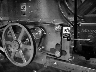
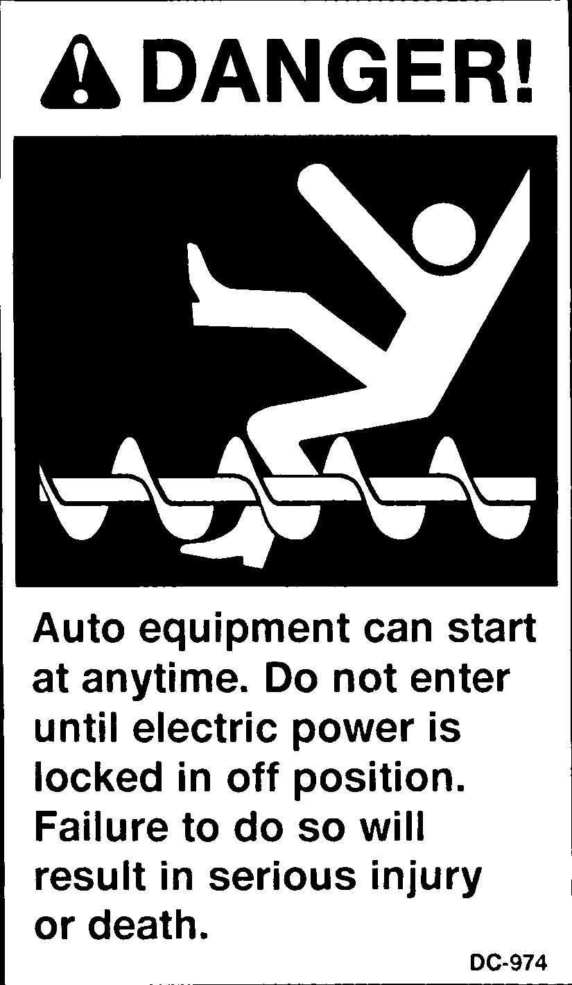
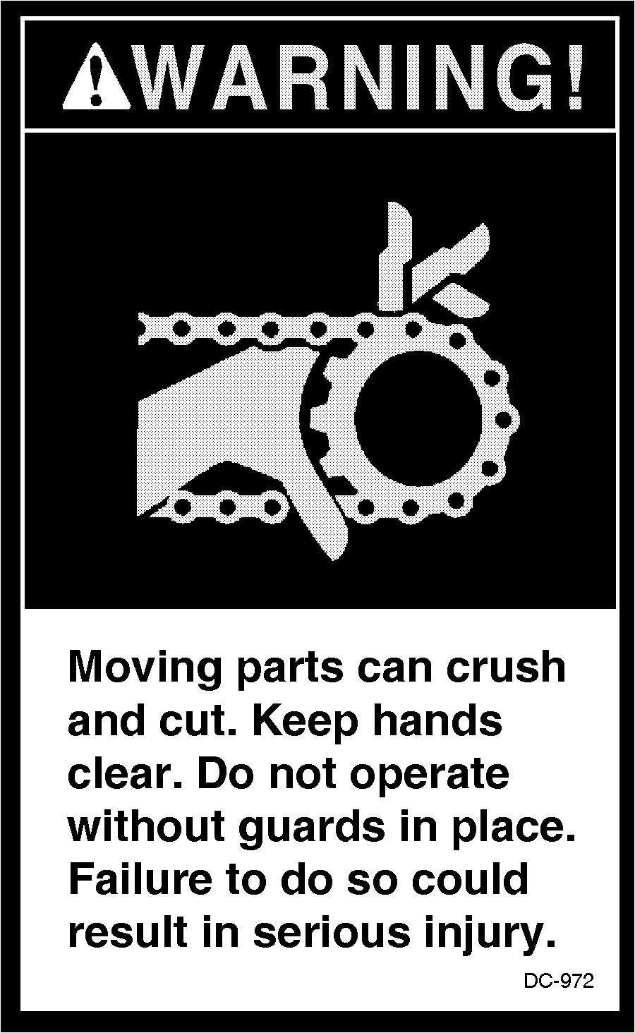
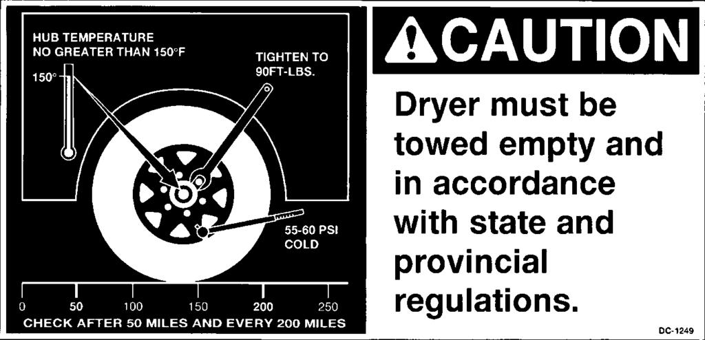
5 Safety Portable Dryer Troubleshooting Grain Systems, Inc. recommends you contact your local power company and have a representative survey your dryer installation, so your wiring will be compatible with their system and you will have adequate power supplied to your unit. A CAREFUL OPERATOR IS THE BEST INSURANCE AGAINST AN ACCIDENT Safety decals should be read and understood by all people in and around the dryer area. If the following safety decals are not displayed on your dryer, or if they are damaged, contact Grain Systems, Inc. for replacement. 4
6 Safety 5

7 Safety Portable Dryer Troubleshooting 6
8 READ THESE INSTRUCTIONS BEFORE OPERATION AND SERVICE SAVE FOR FUTURE REFERENCE 1. Read and understand the operating manual before trying to operate the dryer. 2. Power supply should be OFF for service of electrical components. Use CAUTION in checking voltage or other procedures requiring power to be ON. 3. Check for gas leaks at all gas pipe connections. If any leaks are detected, do not operate the dryer. Shut down and repair before further operation. 4. Never attempt to operate the dryer by jumping or otherwise bypassing any safety devices on the unit. 5. Set pressure regulator to avoid excessive gas pressure applied to burner during ignition and when burner is in operation. Do not exceed maximum recommended drying temperature. 6. Keep the dryer clean. Do not allow fine material to accumulate in the plenum or drying chamber. Safety Precautions Use Caution in the Operation of this Equipment The design and manufacture of this dryer is directed toward operator safety. However, the very nature of a grain dryer having a gas burner, high voltage electrical equipment and high speed rotating parts, does present a hazard to personnel, which can not be completely safeguarded against, without interfering with efficient operation and reasonable access to components. Use extreme caution in working around high speed fans, gas-fired heaters, augers and auxiliary conveyors, which may start without warning when the dryer is operating on automatic control. 7. Use CAUTION in working around high speed fans, gas burners, augers and auxiliary conveyors which START AUTOMATICALLY. 8. Do not operate in any area where combustible material will be drawn into the fan. 9. Before attempting to remove and reinstall any propeller, make certain to read the recommended procedure listed within the servicing section of the manual. 10. Clean grain is easier to dry. Fine material increases resistance to airflow and requires removal of extra moisture. This product is intended for the use of grain handling only. Any other use is considered a misuse of the product. Some edges of the product components can be sharp. It is recommended that each component of this product be examined to determine if there are any safety considerations to be taken. Any and all necessary personal protective equipment should be worn at all tines when handling, assembling, installing and operation of the product and/or components. Guards are removed for illustration purpose only. All guards must be in place before/during operation. KEEP THE DRYER CLEAN DO NOT ALLOW FINE MATERIAL TO ACCUMULATE IN THE PLENUM CHAMBER OR SURROUNDING THE OUTSIDE OF THE DRYER Continued safe, dependable operation of automatic equipment depends, to a great degree, upon the owner. For a safe and dependable drying system, follow the recommendations within this manual, and make it a practice to regularly inspect the operation of the unit for any developing problems or unsafe conditions. Take special note of the safety precautions listed at left before attempting to operate the dryer. 7
9 Safety Sign-Off Sheet Portable Dryer Troubleshooting Date Employer s Signature Employee 8
10 Wiring Reference Safety Voltage Check Points FAN # Error Message RESULT Fan # Housing High Temperature J5-12 J1-7 J5-12 J1-8 J5-12 J2-7 J5-12 J2-8 J5-12 J3-7 J5-12 J3-8 12VDC Burner # Vapor High Temperature J5-12 J1-5 J5-12 J1-6 J5-12 J2-5 J5-12 J2-6 J5-12 J3-5 J5-12 J3-6 12VDC Burner # Flame not Detected J5-12 J1-9 J5-12 J1-10 J5-12 J2-9 J5-12 J2-10 J5-12 J3-9 J5-12 J VDC Plenum # High Temperature J5-12 J1-11 J5-12 J1-12 J5-12 J2-11 J5-12 J2-12 J5-12 J3-11 J5-12 J VDC Burner # Shutdown Loss of Airflow J5-12 J1-13 J5-12 J1-14 J5-12 J2-13 J5-12 J2-14 J5-12 J3-13 J5-12 J3-14 Note 1 Fan # Failure No Airflow J5-12 J1-13 J5-12 J1-14 J5-12 J2-13 J5-12 J2-14 J5-12 J3-13 J5-12 J3-14 Note 2 Fan # cannot Start Check Air Switch J5-12 J1-13 J5-12 J1-14 J5-12 J2-13 J5-12 J2-14 J5-12 J3-13 J5-12 J3-14 Note /1200/ /2300/ /3400/3600 Lower or Left Fixed Grain J5-12 J1-19 J5-12 J1-19 J5-12 J1-19 Lower Adjustable or Right Fixed Grain J5-12 J4-19 J5-12 J4-19 J5-12 J4-19 Middle Fixed Grain J5-12 N/A J5-12 N/A J5-12 J4-4 Middle Adjustable Grain J5-12 N/A J5-12 N/A J5-12 J4-8 Upper Fixed Grain J5-12 N/A J5-12 J4-4 J5-12 J4-2 Upper Adjustable Grain J5-12 N/A J5-12 J4-8 J5-12 J4-6 Misc Errors Auxilliary Safety Shutdown J5-12 J1-20 Note: Motor Overload J5-12 J This error will occur if the fan and burner were both operating and Grain Discharge Warning J5-12 J5-5 the air switch opens which indicates loss of static pressure. Maxon Valve Shut Warning J5-12 J volts should be present if the fan is on. Unknown Safety Error J5-12 J This error will occur if after the fan has started the air switch does 20 Second Safety Circuit Failure J5-12 J5-6 not detect any static pressure. 12 volts should be present if the fan is on. 3 The condition for this error will occur if the air switch is stuck in the closed postition. No voltage should be present if the dryer is stopped. 9
11 Programming Portable Dryer Troubleshooting Programming Instructions for EMCS Grain Dryers 1. Turn Control Power on dryer to off. 2. Locate programming jack (P7) on back of computer. (See page 13). 3. Plug the DB-9 jack of the programmer into the computer's jack. 4. Be sure that the rotary switch on the programmer is set to position Turn on Control Power to the dryer. 6. The four (4) lights on the programmer will come on, then three (3) will go out leaving the power light still on. 7. Push the start button on the programmer to start the transfer of Software. 8. The busy light will flash until the transfer process is complete. 9. When completed the pass light will flash indicating a successful transfer. 10. If the fail light flashes then check your connections and repeat the above process. 11. Turn Control Power on dryer to off and remove the cable. 12. Turn on the dryer and the opening screens should indicate the newer version of software. 10
12 Programming EMCS Display Board DISPLAY RIBBON P1 COMMUNICATIONS CABLE TO I/O BOARD P8 P6 BATTERY (TIC) U P3 TO START & STOP SWS. TO START SW. P7 PROGRAMMER JACK (DB9) COMPUTER PROGRAMMING JACK SOUND S1 P5 P4 KEY PAD RIBBON TO STOP SW. 11
13 Wiring Reference Portable Dryer Troubleshooting Input/Output Board Identification 12 VOLT DC INPUTS 120 VOLT AC OUTPUTS +12 LIMIT OUTPUT 12 VOLT DC NEUTRAL METERING ROLL INPUT 12 VOLT DC NEGATIVE 12 VOLT DC NEGATIVE SAFETY CIRCUIT INPUT +12 VOLT LIMIT OUTPUT FLAME SENSOR RETURN OUT OF GRAIN SENSOR MAXON VALVE SENSOR J LIMIT OUTPUT 12 VOLT DC NEGATIVE 12 VOLT DC NEGATIVE 12 VOLT DC NEGATIVE +12 VOLT LIMIT OUTPUT +12 VOLT LIMIT OUTPUT REAR DISCHARGE M.C. THERMOSTAT N.O. TERM #4 M.C. THERMOATAT N.C. TERM #6 120VAC POWER (INPUT) AC NEUTRAL 120VAC POWER (INPUT) AC NEUTRAL AC NEUTRAL AC NEUTRAL AC NEUTRAL AC NEUTRAL FAN #1 POWER FAN #2 POWER J VAC POWER (OUTPUT) AC NEUTRAL 120VAC POWER (OUTPUT) AC NEUTRAL AC NEUTRAL AC NEUTRAL AC NEUTRAL BURNER #1 POWER BURNER #2 POWER BURNER #3 POWER MERCOID SFTY FAN#1 (CAN) LOWER ADJ. GRAIN HIGH LIMIT MERCOID SFTY FAN#2 (CAN) MERCOID SFTY FAN#4 (CAN) LOW MERCURY SWITCH (BO) MOTOR OVERLOADS MOISTURE CONTROL ADJ. GRAIN (MIDDLE) J SPEED UNLOAD 1 SPEED UNLOAD UNLOAD BYPASS LOAD SWITCH AUTO LOAD SWITCH ON BATCH MODE JUMPER J1-9 TO J5-6 IS A HARDWARE TIMER FOR THE FLAME SENSOR SHUTDOWN JUMPER J5-2 TO J5-20 IS A CONNECTION FOR THE MAXON VALVE SENS0R JUMPER J4-12 TO J5-10 IS A HARDWARE TIMER FOR THE SAFETY SHUTDOWNS JUMPER J1-20 TO J5-8 IS A CONNECTION FOR THE USER SUPPLLIED SAFETY JUMPERS MUST BE INSTALLED FOR THE INPUT/OUTPUT BOARD TO OPERATE!! ADJ. GRAIN (UPPER) FIXED GRAIN (MIDDLE) FIXED GRAIN (UPPER) CONTINUOUS FLOW MERCOID SAFTY FAN#3 (CAN) OUT OF GRAIN FOR LOAD #2 JUMPERS TO BE INSTALLED FOR E-COOL INSTALL JUMPER FROM J6-13 TO J1-5 INSTALL JUMPER FROM J6-14 TO J1-19 INSTALL JUMPER FROM J6-16 TO J5-5 INSTALL JUMPER FROM J6-17 TO J4-19 HI-HEAT THERMOSTAT (BO) BURNER #6 AUTO BURNER #6 ON FAN #6 AIR FAN #6 PLENUM FAN #6 FLAME DETECTION FAN #6 HOUSING HIGH LIMIT FAN #6 VAPOR HIGH LIMIT FAN #6 AUTO FAN #6 ON J LO-HEAT THERMOSTAT (BO) BURNER #5 AUTO BURNER #5 ON FAN #5 AIR FAN #5 PLENUM FAN #5 FLAME DETECTION FAN #5 HOUSING HIGH LIMIT FAN #5 VAPOR HIGH LIMIT FAN #5 AUTO FAN #5 ON FAN #3 POWER FAN #4 POWER FAN #5 POWER FAN #6 POWER UNLOAD POWER BUR # 4 NEUTRAL BUR # 3 NEUTRAL FAN # 4 NEUTRAL FAN # 3 NEUTRAL LOAD #2 NEUTRAL J BURNER #4 POWER BURNER #5 POWER BURNER #6 POWER LOAD POWER SCR POWER FAN #1 NEUTRAL FAN #2 NEUTRAL UNLOAD NEUTRAL LOAD NEUTRAL SCR NEUTRAL BURNER #4 AUTO BURNER #4 ON FAN #4 AIR FAN #4 PLENUM FAN #4 FLAME DETECTION FAN #4 HOUSING HIGH LIMIT FAN #4 VAPOR HIGH LIMIT FAN #4 AUTO FAN #4 ON J BURNER #3 AUTO BURNER #3 ON FAN #3 AIR FAN #3 PLENUM FAN #3 FLAME DETECTION FAN #3 HOUSING HIGH LIMIT FAN #3 VAPOR HIGH LIMIT FAN #3 AUTO FAN #3 ON LOAD #2 POWER MAXON POWER BUR #6 NEUTRAL BUR #5 NEUTRAL FAN #6 NEUTRAL FAN #5 NEUTRAL THERMOSTAT 110VAC (BO) NC NC J PROCESS LIGHT BURNER #1 NEUTRAL BURNER #2 NEUTRAL MAXON NEUTRAL AC NEUTRAL LO-HEAT POWER (BO) HI-HEAT POWER (BO) NC M.R.H POT 3 USER SUPPLIED SAFETY BURNER #2 AUTO BURNER #2 ON FAN #2 AIR FAN #2 PLENUM FAN #2 FLAME DETECTION FAN #2 HOUSING HIGH LIMIT FAN #2 VAPOR HIGH LIMIT FAN #2 AUTO FAN #2 ON J LOWER GRAIN HIGH LIMIT BURNER #1 AUTO BURNER #1 ON FAN #1 AIR FAN #1 PLENUM FAN #1 FLAME DETECTION FAN #1 HOUSING HIGH LIMIT FAN #1 VAPOR HIGH LIMIT FAN #1 AUTO FAN #1 ON SCR P1 & V1 FROM BR#1 (BO) M.R.H POT 2 M.R.L POT 2 & HI SOLENOID BUR#2 (BO) THERMOSTAT SENSOR S1 SENSOR 2 LOWER. SENSOR 2 UPPER ENERGENCY COOLING AUX #6 B-COMMON EMERGENCY COOLING NC J M.R.L POT 3 & HIGH SOLENOID BUR#1 (BO) SCR P3 & V1 FROM BR#2 (B0 SENSOR 1 LOWER SENSOR 1 UPPER THERMOSTAT SENSOR S2 AUX #6 A-N.C. EMERGENCY COOLING EMERGENCY COOLING NC NC ** IMPORTANT--JUMPERS LISTED ABOVE MUST BE INSTALLED 12
14 Switch Replacement Switch Replacement for EMCS Dryer Switch N/O Contact Block - Part No. D Switch Light Block - D
15 Wiring Reference Portable Dryer Troubleshooting 1100 Series Control Box Wiring DESCRIPTION 1100 FAN TO CONTROL BOX WIRING WIRING 42 TOTAL TERMINALS VOLTAGE COLOR 14 SAFETY CIRCUIT USED ON SINGLE FAN NAT GAS ONLY OK OTHER SIDE (N/C) SAFETY J5-8 OR J AIR PRESSURE SWITCH +12VDC HOUSING HIGH LIMIT VAPOR HIGH LIMIT (LP ONLY) FLAME DETECTION PLENUM RELAY CONTACTS LOCATED IN DRYER FAN CAN BOX LEFT FIXED GRAIN HI LIMIT *REAR DISCHARGE RIGHT FIXED GRAIN HI LIMIT AIR PRESSURE SWITCH BURNER POWER BURNER NEUTRAL BURNER LIGHT MAXON POWER MAXON NEUTRAL OUT OF GRAIN SENSOR * LEFT METERING ROLL SENSOR * RIGHT METERING ROLL SENSOR METERING ROLL 12 VOLTS MERCURY SWITCH LOCATED ON TOP OF DRYER DRYER SAFETY CIRCUIT ALWAYS STARTS ON J5-8 AND ENDS ON J4-12.USING THE J5-12 TERMINAL FOR NEGATIVE, THERE SHOULD BE 12 VOLTS DC ON EACH TERMINAL FROM J5-8 TO J4-12. WHEN CHECKING FOR 12 VOLTS DC ALWAYS PUT THE NEGATIVE PROBE OF VOLT METER TO TERMINAL J5-12 RED J5-8 NEED JUMPER RED J5-8 OR YEL J1-7 PUR J1-5 YEL OR J1-9 CUSTOMER SUPPLIED SAFETY BLK J1-20 METERING ROLL NEUTRAL BLK J5-12 TEMP SENSORS TEMP SENSORS WORK LIGHT NEED JUMPER J9-3 AC VAC NEUT (WHITE) 120 VAC (BLACK) SAFETY CIRCUIT IN BOLD IS FOR FLAME DETECTION ONLY. EACH OF THE TERMINALS CONNECTED TO IT CAN LOOSE 12 VDC FOR 20 SECONDS BEFORE A SHUTDOWN OCCURS. THIS GIVES THE BURNER CIRCUIT TIME TO SENSE FLAME. SCR 2 J6-4 U-COM CONTROL POT P2 (PUR) CONTROL POT P3 (PUR) UNLOAD AUX COM(ORANGE) ALL OTHER SAFETY CONNECTIONS MUST HAVE 12 VDC U-N/O UNLOAD AUX N/O(ORANGE) PRESENT AT ALL TIMES TO OPERATE PROPERLY. L-COM LOAD AUX COM (YELLOW) AUX CONTACT POINTS FOR LOAD AND UNLOAD SYSTEMS ALL VOLTAGE SUPPLIED BY USER L-N/O LOAD AUX N/O (YELLOW) *LOCATED AT REAR OF DRYER 1100EW98.PRT REV. DATE 4/10/98 ALL SAFETIES MUST BE CLOSED FOR DRYER TO OPERATE RED BRN RED BLK 120VAC FOR AUX UNLOAD CONTACTOR COIL 120VAC FOR AUX LOAD CONTACTOR COIL BLU OR OR OR BLU BLK WHT BRN PUR WHT BLK YEL BLU RED WHT BLK RED J1-11 J1-19 J5-5 J4-19 J4-12 J1-13 J9-16 J7-4 B1 J7-3 J7-8 J5-4 J5-16 J5-19 J VDC S1 S2 L1 J8-16 J8-9 J8-18 J8-8 J8-12 J9-17 J8-20 J8-10 J VOLTS DC (RED) 12 VOLTS DC (RED) 12 VOLTS DC (RED) 12 VOLTS DC (RED) 12 VOLTS DC (RED) 12 VOLTS DC (RED) 12 VOLTS DC (RED) 12 VOLTS DC (RED) 12 VOLTS DC (RED) MOTOR OVERLOADS 12 VOLTS DC (BLUE) 120 VAC (BLACK) 120 VAC NEUT (WHITE) 120 VAC (BLUE) 120 VAC (BLACK) 120 VAC NEUT (WHITE) 12 VOLTS DC (YELLOW) METER ROLL PULSE (PUR) NO LONGER USED 12 VOLTS DC (RED) 12 VOLTS DC (RED) 12 VOLTS DC NEG (WHITE) TEMP SENSOR TEMP SENSOR 120 VAC NEUT (WHITE) 120 VAC (ORANGE) 120 VAC NEUT (WHITE) 120 VAC (YELLOW) 120 VAC NEUT (WHITE) 120 VAC (BLUE) (ORANGE) (ORANGE) 120 VAC (BLACK) 120 VAC NEUT (WHITE) 120 VAC (ORANGE) CONTROL POT P1 (PUR)
16 Wiring Reference 1100 Series Control Box Wiring (New Version) 15
17 Wiring Reference Portable Dryer Troubleshooting 1200 Series Control Box Wiring DESCRIPTION WIRING 52 TOTAL TERMINALS TERMINAL VOLTAGE COLOR SAFETY CIRCUIT HOOK OTHER SIDE OF (N/C) SAFETY TO J5-8 OR J TOTAL TERMINALS 15 - RED 4 - BLUE 1 - WHITE/BLACK 3 - BLACK (1-16GA) 9 - WHITE (1-16GA 2 - BROWN 4 - PURPLE 4 - ORANGE) AIR PRESSURE SWITCH +12VDC FAN #2 HOUSING HIGH LIMIT FAN #2 VAPOR HIGH LIMIT RELAY CONTACTS LOCATED IN FAN CAN CONTROL BOX FAN #2 FLAME DETECTION FAN #1 HOUSING HIGH LIMIT FAN #1 VAPOR HIGH LIMIT RELAY CONTACTS LOCATED IN FAN CAN CONTROL BOX FAN #1 FLAME DETECTION FAN #2 PLENUM FAN #1 PLENUM FIXED GRAIN HIGH LIMIT *REAR DISCHARGE ADJ. GRAIN HIGH LIMIT FAN #2 PRESSURE SWITCH FAN #1 PRESSURE SWITCH BURNER #2 POWER BURNER #2 NEUTRAL BURNER #1 POWER BURNER #1 NEUTRAL BURNER #2 LIGHT BURNER #1 LIGHT MAXON POWER MAXON NEUTRAL OUT OF GRAIN SENSOR *LEFT METERING ROLL SENSOR *LOCATED AT REAR OF DRYER 1200EW98.PRT REV. DATE 3/5/98 MERCURY SWITCH LOCATED ON TOP OF DRYER NEED JUMPER *RIGHT METERING ROLL SENSOR BLU J5-19 NO LONGER USED BLK METERING ROLL 12 VOLTS RED J VOLTS DC (RED) CUSTOMER SUPPLIED SAFETY RED 12 VOLTS DC (RED) METERING ROLL NEGATIVE BLK J VOLTS DC NEG (WHITE) TEMP SENSOR TEMP SENSOR WORK LIGHT NEED JUMPER AUX CONTACT POINTS FOR LOAD AND UNLOAD SYSTEMS ALL VOLTAGE SUPPLIED BY USER OR RED OR RED RED BRN RED RED RED YEL PUR OR YEL PUR OR YEL BLU OR OR RED MOTOR OVERLOADS BLU BLU BLK WHT BLK WHT BRN BRN PUR WHT BLK YEL WHT BLK RED 120VAC FOR AUX UNLOAD CONTACTOR COIL 120VAC FOR AUX LOAD CONTACTOR COIL J5-8 J5-8 J1-8 J1-6 J1-10 J1-7 J1-5 J1-9 J1-12 J1-11 J1-19 J5-5 J4-19 J4-12 J1-14 J1-13 J9-18 J7-6 J9-16 J7-4 B2 B1 J7-3 J7-8 J5-4 J5-16 J VDC S1 S2 L1 J9-3 AC 1 J8-16 J8-9 J8-18 J8-8 J8-14 J9-19 J8-12 J9-17 J8-20 J8-10 J6-1 SCR 2 J6-4 U-COM U-N/O L-COM L-N/O 12 VOLTS DC (RED) 12 VOLTS DC (RED) 12 VOLTS DC (RED) 12 VOLTS DC (RED) 12 VOLTS DC (RED) 12 VOLTS DC (RED) 12 VOLTS DC (RED) 12 VOLTS DC (RED) 12 VOLTS DC (RED) 12 VOLTS DC (RED) 12 VOLTS DC (RED) 12 VOLTS DC (RED) 12 VOLTS DC (RED) 12 VOLTS DC (BLUE) 12 VOLTS DC (BLUE) 120 VAC (BLACK) 120 VAC NEUT (WHITE) 120 VAC (BLACK) 120 VAC NEUT (WHITE) 120 VAC (BROWN) 120 VAC (BROWN) 120 VAC (BLACK) 120 VAC NEUT (WHITE) 12 VOLTS DC (YELLOW) METER ROLL PULSE (PUR) TEMP SENSOR (ORANGE) TEMP SENSOR (ORANGE) 120 VAC (BLACK) 120 VAC NEUT (WHITE) 120 VAC (BLACK) 120 VAC NEUT (WHITE) 120 VAC (ORANGE) 120 VAC NEUT (WHITE) 120 VAC (YELLOW) 120 VAC NEUT (WHITE) 120 VAC (BLUE) 120 VAC NEUT (WHITE) 120 VAC (BLUE) 120 VAC NEUT (WHITE) 120 VAC (ORANGE) CONTROL POT P1 (PUR) CONTROL POT P2 (PUR) CONTROL POT P3 (PUR) UNLOAD AUX COM(ORANGE) UNLOAD AUX N/O(ORANGE) LOAD AUX COM (YELLOW) LOAD AUX N/O (YELLOW) ALL SAFETIES MUST BE CLOSED FOR DRYER TO OPERATE 16
18 Wiring Reference 1200 Series Control Box Wiring (New Version) 17
19 Wiring Reference Portable Dryer Troubleshooting 1100 Fan Lower Control Box Interconnect Strip J9-1 AC-1 EMERGENCY COOLING JUMPERS INSTALL J6-13 TO J1-5 INSTALL J6-14 TO J1-19 INSTALL J6-16 TO J5-5 INSTALL J6-17 TO J4-19 J9-3 LOAD EMI FILTER D VB1 LINE J9-3 L1 B1 S1 BLACK VAC - OUTSIDE LIGHT BROWN VAC - BURNER #1 LIGHT ORANGE - TEMPERATURE SENSOR ORANGE - TEMPERATURE SENSOR PURPLE - CONTROL POT P2 RED - 12 VDC - FAN #1 VAPOR HIGH LIMIT RED - 12 VDC - FAN #1 HOUSING HIGH LIMIT RED - 12 VDC - FAN #1 FLAME DETECTION RED - 12 VDC - FAN #1 PLENUM HIGHT LIMIT BLUE - 12 VDC - FAN #1 AIR SWITCH RED - 12 VDC - LOWER FIXED GRAIN LIMIT RED - 12 VDC - USER SUPPLIED SAFETY RED - 12 VDC - MOTOR OVERLOADS RED - 12 VDC - LOWER ADJUSTABLE GRAIN HIGH LIMIT YELLOW - 12 VDC - OUT OF GRAIN SENSOR S2 SCR2 J1-5 J1-7 J1-9 J1-11 J1-13 J1-19 J1-20 J4-12 J4-19 J5-4 J5-5 J5-8 J5-9 J5-12 J5-16 J5-19 J6-1 J6-4 J7-3 BLACK VAC - MAXON POWER J7-4 WHITE - AC NEUTRAL - BURNER NEUTRAL J7-8 WHITE - AC NEUTRAL - MAXON NEUTRAL J8-8 YELLOW VAC - LOAD POWER J8-9 ORANGE VAC - UNLOAD POWER J8-10 ORANGE VAC - SCR POWER J8-12 WHITE - AC NEUTRAL - FAN #1 NEUTRAL J8-16 WHITE - AC NEUTRAL - UNLOAD NEUTRAL J8-18 WHITE - AC NEUTRAL - LOAD NEUTRAL J8-20 WHITE - AC NEUTRAL - SCR NEUTRAL J9-16 BLACK VAC - BURNER #1 POWER J9-17 BLUE VAC - FAN #1 POWER RED - 12 VDC - REAR DISCHARGE SWITCH RED - 12 VDC - 12 VOLT SUPPLY RED - 12 VDC - 12 VOLT SUPPLY WHITE - 12 VDC NEG - 12 VOLT SUPPLY NEGATIVE PURPLE -TIMING PULSE- LEFT METERING ROLL PULSE PURPLE -TIMING PULSE- RIGHT METERING ROLL PULSE PURPLE - CONTROL POT P1 PURPLE - CONTROL POT P D ENTRELEC TERMINALS 2 - D END STOPS 1 - D BLANK PROTECTOR END I/O BOARD JUMPERS INSTALL J1-9 TO J5-6 INSTALL J5-2 TO J5-20 INSTALL J4-12 TO J5-10 INSTALL J1-20 TO J5-8 18
20 Wiring Reference 1200 Fan Lower Control Box Interconnect Strip J9-1 AC-1 LINE LOAD J9-3 EMI FILTER D VB1 J9-3 L1 B1 B2 S1 S2 SCR2 J1-5 J1-6 J1-7 J1-8 J1-9 J1-10 J1-11 J1-12 J1-13 J1-14 J1-19 J1-20 J4-12 J4-19 J5-4 J5-5 J5-8 J5-9 J5-12 J5-16 J5-19 J6-1 J6-4 J7-3 J7-4 J7-6 J7-8 J8-8 J8-9 J8-10 J8-12 J8-14 J8-16 J8-18 J8-20 J9-16 J9-17 J9-18 J9-19 BLACK VAC - OUTSIDE LIGHT BROWN VAC - BURNER #1 LIGHT BROWN VAC - BURNER #2 LIGHT ORANGE - TEMPERATURE SENSOR ORANGE - TEMPERATURE SENSOR PURPLE - CONTROL POT P2 RED - 12 VDC - FAN #1 VAPOR HIGH LIMIT RED - 12 VDC - FAN #2 VAPOR HIGH LIMIT RED - 12 VDC - FAN #1 HOUSING HIGH LIMIT RED - 12 VDC - FAN #2 HOUSING HIGH LIMIT RED - 12 VDC - FAN #1 FLAME DETECTION RED - 12 VDC - FAN #2 FLAME DETECTION RED - 12 VDC - FAN #1 PLENUM HIGHT LIMIT RED - 12 VDC - FAN #2 PLENUM HIGHT LIMIT BLUE - 12 VDC - FAN #1 AIR SWITCH BLUE - 12 VDC - FAN #2 AIR SWITCH RED - 12 VDC - LOWER FIXED GRAIN LIMIT RED - 12 VDC - USER SUPPLIED SAFETY RED - 12 VDC - MOTOR OVERLOADS RED - 12 VDC - LOWER ADJUSTABLE GRAIN HIGH LIMIT YELLOW - 12 VDC - OUT OF GRAIN SENSOR RED - 12 VDC - REAR DISCHARGE SWITCH RED - 12 VDC - 12 VOLT SUPPLY RED - 12 VDC - 12 VOLT SUPPLY WHITE - 12 VDC NEG - 12 VOLT SUPPLY NEGATIVE PURPLE -TIMING PULSE- LEFT METERING ROLL PULSE PURPLE -TIMING PULSE- RIGHT METERING ROLL PULSE PURPLE - CONTROL POT P1 PURPLE - CONTROL POT P3 BLACK VAC - MAXON POWER WHITE - AC NEUTRAL - BURNER #1 NEUTRAL WHITE - AC NEUTRAL - BURNER #2 NEUTRAL WHITE - AC NEUTRAL - MAXON NEUTRAL YELLOW VAC - LOAD POWER ORANGE VAC - UNLOAD POWER ORANGE VAC - SCR POWER WHITE - AC NEUTRAL - FAN #1 NEUTRAL WHITE - AC NEUTRAL - FAN #2 NEUTRAL WHITE - AC NEUTRAL - UNLOAD NEUTRAL WHITE - AC NEUTRAL - LOAD NEUTRAL WHITE - AC NEUTRAL - SCR NEUTRAL BLACK VAC - BURNER #1 POWER BLUE VAC - FAN #1 POWER BLACK VAC - BURNER #2 POWER BLUE VAC - FAN #2 POWER EMERGENCY COOLING JUMPERS INSTALL J6-13 TO J1-5 INSTALL J6-14 TO J1-19 INSTALL J6-16 TO J5-5 INSTALL J6-17 TO J4-19 I/O BOARD JUMPERS INSTALL J1-9 TO J5-6 INSTALL J5-2 TO J5-20 INSTALL J4-12 TO J5-10 INSTALL J9-1 TO J D ENTRELEC TERMINALS 2 - D END STOPS 1 - D BLANK PROTECTOR ENDS 19
21 Wiring Reference Portable Dryer Troubleshooting Upper Control Box External Wiring BLACK FROM J9-16 TO L1 ON FENWAL BOARD 120VAC POWER WHITE FROM J7-04 TO L2 ON FENWAL BOARD 120VAC NEUTRAL BROWN TO B1 FROM V1 ON FENWAL BOARD 120VAC ORANGE FROM J1-09 TO FLAME DETECTION RELAYS ORANGE FROM J5-08 TO FLAME DETECTION RELAYS WHITE/BLACK STRIP J VDC NEGATIVE YELLOW TO J1-07 FROM HOUSING HIGH LIMIT SWITCH RED FROM J5-08 TO HOUSING & VAPOR HIGH LIMIT SWITCHES PURPLE TO J1-05 FROM VAPOR HIGH LIMIT SWITCH TO FAN CONTROL BOX BLUE FROM J5-08 TO AIRSWITCH COMMON TERMINAL BLUE TO J1-13 FROM AIRSWITCH N.O. TERMINAL TO AIRSWITCH ASSEMBLY WHITE TO S1 FROM RIGHT GRAIN TEMPERATURE SENSOR BLACK TO S2 FROM RIGHT GRAIN TEMPERATURE SENSOR RED FROM J1-11 TO LEFT GRAIN HIGH LIMIT SWITCH ORANGE TO J1-19 FROM LEFT GRAIN HIGH LIMIT SWITCH PURPLE J7-03 MAXON POWER 120VAC (NATURAL GAS ONLY) WHITE J7-08 MAXON 120VAC NEUTRAL (NATURAL GAS ONLY) BROWN FROM J1-19 TO REAR DISCHARGE SWITCH ORANGE TO J5-05 FROM REAR DISCHARGE SWITCH RED 16 GA. A+ SCR DRIVE MOTOR BLACK 16 GA. A- SCR DRIVE MOTOR GREEN 16 GA. SCR DRIVE MOTOR GROUND BLACK FROM J5-09 TO LOAD MERCURY SWITCH BLACK TO J5-04 FROM LOAD MERCURY SWITCH WHITE FROM J9-03 TO OUTSIDE LIGHT AC NEUTRAL RED FROM L1 120VAC TO OUTSIDE LIGHT POWER TO LOWER JUNCTION BOX TO UPPER JUNCTION BOX YELLOW FROM J1-05 TO PLENUM HIGH LIMIT SWITCH WHITE TO S1 FROM GRAIN TEMPERATURE SENSOR BLACK TO S2 FROM GRAIN TEMPERATURE SENSOR BLUE TO J1-11 FROM PLENUM HIGH LIMIT SWITCH YELLOW FROM J1-05 TO PLENUM HIGH LIMIT SWITCH RED FROM J5-05 TO RIGHT GRAIN HIGH LIMIT SWITCH ORANGE TO J4-19 FROM RIGHT GRAIN HIGH LIMIT SWITCH TO PLENUM AND RIGHT FIXED GRAIN HIGH LIMIT SWITCHES AND TEMPERATURE SENSORS 20
22 Wiring Reference Fan Housing and Vapor Hi-Limit Circuit 21
23 Wiring Reference Portable Dryer Troubleshooting Plenum Hi-Temperature Switch 22
24 Wiring Reference Fixed Grain Hi-Limit 23
25 Wiring Reference Portable Dryer Troubleshooting Grain & Plenum Hi-Limit Locations LOAD MERCURY SWITCH OUTSIDE LIGHT RIGHT FIXED GRAIN HIGH LIMIT TEMP. SENSORS UPPER JUNCTION BOX PLENUM UNLOAD MOTOR 11XX FAN AIR SWITCH LOWER JUNCTION BOX SOLENOID BURNER HI-LOW THERMO SCR YELLOW J1-05 BLUE J1-11 TO UPPER CONTROL BOX TO LOWER JUNCTION BOX PLENUM HIGH LIMIT SWITCH D DEGREE LOAD MOTOR RIGHT GRAIN HIGH LIMIT SWITCH D DEGREE LEFT FIXED GRAIN HIGH LIMIT TEMP. SENSORS GAS PIPE TRAIN BLUE J1-11 ORANGE J4-19 YELLOW J1-05 RED J5-05 LEFT GRAIN HIGH LIMIT SWITCH D DEGREE RED J1-11 ORANGE J
26 Wiring Reference Two Fan Plenum and Grain Limit Switch Wiring FIXED GRAIN HIGH LIMIT SWITCH D DEGREE FAN #2 PLENUM HIGH LIMIT SWITCH D DEGREE LOAD MERCURY SWITCH OUTSIDE LIGHT ADJUSTABLE GRAIN HIGH LIMIT TEMP. SENSORS UPPER JUNCTION BOX 12XX SOLENOID PLENUM #2 BURNER #2 HI-LOW THERMO FAN #2 AIR SWITCHES BURNER #1 HI-LOW THERMO PLENUM #1 SOLENOID FAN #1 UNLOAD MOTOR SCR MAXON 2FNLMTSW98.PRT REV. DATE 4/5/98 LOAD MOTOR FIXED GRAIN HI-LIMIT AND THERMO SENSORS FAN #1 PLENUM HIGH LIMIT SWITCH D DEGREE RED TO J1-11 ORANGE TO J1-19 TO LOWER JUNCTION BOX YELLOW TO J1-12 BLUE TO J1-11 RED TO J
27 Wiring Reference Portable Dryer Troubleshooting Rear Discharge & Emergency Cooling Circuit 26
28 Wiring Reference Rear Discharge Mercury Switch LOOSEN SCREWS ON BRACKET TO CHANGE SENSITIVITY OF REAR DISCHARGE SWITCH POSITIONED WITH LID CLOSED AND SJOW 18/2 CORD POINTED TOWARDS THE FRONT OF THE DRYER CONNECT INSIDE METER ROLL BOX TO BROWN AND ORANGE WIRES. CONNECT TO SJOW CORD INSIDE LRL BOX 27
29 Wiring Reference Portable Dryer Troubleshooting Adjustable Hi-Limit & Emergency Cooling Circuit 28
30 Wiring Reference Motor Overloads 29
31 Wiring Reference Portable Dryer Troubleshooting Air Pressure Switch 12 VOLT SOURCE DC POSITIVE J VOLT DC NEGATIVE J5-8 J1-8 J1-6 J1-10 J1-7 J1-5 J J4 INPUT/OUTPUT BOARD TERMINAL LOCATIONS J1-12 J1-11 J V DC SOURCE FROM MOTOR OVERLOADS J6-14 J5-5 J4-19 J3 FAN #2 PRESSURE SWITCH BLUE J6-17 J4-12 J1-14 BLUE FAN #1 PRESSURE SWITCH J1-13 BLUE J2 BLUE PRESSURE SWITCH SAFETY CIRCUIT 1413 J 1 30
32 Wiring Reference Air Pressure Switch Drawing BACKVIEW OF AIR SWITCH ASSEMBLY C N.C. N.O. CALIBRATED WITH DIAPHRAGM VERTICAL HIGH TO UPPER CONTROL BOX BLUE J VDC POSITIVE BLUE J1-13 AIRFLOW (N.O.) UPPER JUNCTION BOX LOAD MERCURY SWITCH OUTSIDE LIGHT RIGHT FIXED GRAIN HIGH LIMIT TEMP. SENSORS PLENUM UNLOAD MOTOR 11XX FAN AIR SWITCH LOWER JUNCTION BOX SOLENOID SCR LOAD MOTOR LEFT FIXED GRAIN HIGH LIMIT TEMP. SENSORS GAS PIPE TRAIN 31
33 Wiring Reference Portable Dryer Troubleshooting Out of Grain Safety Circuit 32
34 Wiring Reference Out of Grain Safety Circuit Location UP FRONT VIEW OF OPEN BOX BLACK WHITE SJOW 18/2 WIRE EXITS THROUGH BOX COVER REMOVE THESE EARS LEADS MUST BE IN THIS POSITION FOR PROPER OPERATION LOAD MERCURY SWITCH OUTSIDE LIGHT RIGHT FIXED GRAIN HIGH LIMIT TEMP. SENSORS UPPER JUNCTION BOX PLENUM UNLOAD MOTOR 11XX FAN AIR SWITCH LOWER JUNCTION BOX SOLENOID BURNER HI-LOW THERMO SCR LOAD MOTOR LEFT FIXED GRAIN HIGH LIMIT TEMP. SENSORS GAS PIPE TRAIN 33
35 Wiring Reference Portable Dryer Troubleshooting Upper Junction Box Drawing TO LOAD MERCURY SWITCH LOAD MERCURY SWITCH OUTSIDE LIGHT RIGHT FIXED GRAIN HIGH LIMIT TEMP. SENSORS UPPER JUNCTION BOX PLENUM UNLOAD MOTOR 11XX FAN AIR SWITCH LOWER JUNCTION BOX SOLENOID BURNER HI-LOW THERMO SCR LOAD MOTOR LEFT FIXED GRAIN HIGH LIMIT TEMP. SENSORS WHITE GAS PIPE TRAIN BLACK WHITE RED BLACK J9-03 L1 BLACK WHITE TO 12VDC J5-09 BLACK J5-04 TO OUTSIDE LIGHT FIXTURE TO UPPER CONTROL BOX 34
36 Wiring Reference Meter Roll Sensor J5-09 J5-19 J5-12 LEFT METER ROLL SENSOR TO REAR JUNCTION BOX RIGHT METER ROLL SENSOR RED BLACK BLUE J5-12 J5-19 TO REAR DISCHARGE SWITCH J5-09 RED 12VDC POS BLACK OR WHITE/BLACK STRIP 12VDC NEG YELLOW LEFT METER PULSE RETURN BLUE RIGHT METER PULSE RETURN ORANGE REAR DISCHARGE RETURN BROWN 12VDC TO DISCHARGE SWITCH NOTE: RIGHT SENSOR IS NO LONGER USED ON DRYERS MANUFACTURED AFTER MARCH 1, 1997 ORANGE BROWN YELLOW BLACK RED J5-16 J5-05 J
37 Wiring Reference Portable Dryer Troubleshooting Meter Roll Sensor Wiring METER ROLL SENSOR 12 Volt + 12 Volt - 12 Volt + T-1 Board Meter Roll Board Meter Roll T-2 T-3 Pulse 12 Volt - T-1 T-2 T-3 Pulse 1997 Dryers have only 1 meter roll board. Remove one meter roll board and tie the 2 T-3 wires together. J5-8 J1-7 J1-5 J1-9 J1-11 J1-19 J5-5 J4-19 J4-12 J1-13 J9-16 J7-4 B1 J7-3 J7-8 J5-4 J5-16 J5-19 J5-9 J1-20 J5-12 S1 S J5 J4 J3 J2 J 1 36
38 Wiring Reference Meter Roll Reversing YOU MUST ENTER INTO THE DRYER PARMETER MODE BY PRESSING THE INCREASE AND DECREASE BUTTONS SIMULTANIOUSLY. YOU WILL HAVE THE FOLLOWING OPTIONS LISTED: SHUTDOWN HISTORY (PRESS ENTER) DRYER MODEL # (IE. 1112) FAN DELAY (DEFAULT = 5) FILL AUGER (DEFAULT = END) BPH FACTOR (DEFAULT = 1.0) TEST METER ROLL (DEFAULT = YES) TEST AIR SWITCH (DEFAULT = YES) M.R. REVERSE (DEFAULT = NO) <- CHANGE TO YES * REVERSE DELAY (DEFAULT = 60) * REVERSE TIME (DEFAULT = 1) * DISPLAYED ONLY IF M.R. REVERSE IS CHANGED TO YES REVERSE DELAY = METER ROLLS NORMAL ROTATION TIME (AMOUNT OF TIME METER ROLLS WILL OPERATE BEFORE THEY WILL BEGIN REVERSE ROTATION) REVERSE TIME = METER ROLLS REVERSE ROTATION TIME (AMOUNT OF TIME METER ROLLS WILL OPERATE IN THE REVERSED ROTATION MODE) EXAMPLE: REVERSE DELAY = 10 MINUTES REVERSE TIME = 1 MINUTE NOTE: WHEN INSTALLING RELAY BASE NOTE POSITION OF SLOTS FOR RELAY!! ORANGE TO SCR DRIVE BOARD A+ A PURPLE JUMPER WIRES SHOULD GO BETWEEN: TERMINALS 4 AND 5 TERMINALS 1 AND 8 LOCATE THE ORANGE AND PURPLE WIRES COMING FROM THE SCR DRIVE BOARD GOING TO THE TERMINAL STRIP AND INSERT THE RELAY AS SHOWN BLACK WHITE J7-17 J8-20 (110 VAC CONTROL) (110 VAC NEUTRAL) IMPORTANT YOU MUST ADD A JUMPER WIRE FROM J9-09 TO J7-16 IN THE LOWER CONTROL BOX. PURPLE A- TO A+ DC DRIVE MOTOR ORANGE 37
39 Wiring Reference Portable Dryer Troubleshooting Lower Junction Box Wiring TO LEFT FIXED GRAIN HIGH LIMIT AND TEMPERATURE SENSORS BLACK S2 ORANGE J1-19 WHITE S1 RED J1-11 SJOW 18/2 WIRE NATURAL GAS DRYERS ONLY BLACK TO MAXON RED FROM J5-09 TO 12VDC POSITIVE TERMINAL ON METER ROLL SENSOR BLACK FROM J5-12 TO 12V NEGATIVE TERMINAL ON METER ROLL SENSOR YELLOW FROM J5-16 TO LEFT METER ROLL SENSOR BLUE FROM J5-19 TO RIGHT METER ROLL SENSOR BROWN FROM J1-19 TO DISCHARGE SWITCH ORANGE FROM J5-05 TO DISCHARGE SWITCH RED 16 GA. A+ TO SCR DRIVE MOTOR BLACK 16 GA. A- TO SCR DRIVE MOTOR GREEN 16 GA. TO SCR DRIVE GROUND WIRES GO TO UPPER CONTROL BOX UPPER JUNCTION BOX LOAD MERCURY SWITCH OUTSIDE LIGHT RIGHT FIXED GRAIN HIGH LIMIT TEMP. SENSORS PLENUM UNLOAD MOTOR 11XX FAN AIR SWITCH LOWER JUNCTION BOX SOLENOID BURNER HI-LOW THERMO SCR LOAD MOTOR LEFT FIXED GRAIN HIGH LIMIT TEMP. SENSORS GAS PIPE TRAIN WHITE TO MAXON PURPLE J7-03 WHITE J7-08 TO SCR DRIVE MOTOR TO REAR OF DRYER 38
40 New Fenwal Board Wiring Wiring Reference The B. GND terminal is used to ground the burner and to complete the flame current signal circuit. This terminal is new for systems that used the older version of the Fenwal board. This terminal must be connected to the burner (chassis) ground not only to ensure the best, long term, stable flame signal, but also to ground the burner for proper sparking. The use of a burner ground terminal eliminates the problem of loss of flame sense signal due to a missing or loose neutral or ground (green) wire at the 120 VAC power source. The new board has been designed such that reversing the polarity of the 120 VAC line does not cause a loss of flame signal. Thus providing a more reliable flame signal along with a reduction of nuisance lockouts, due to its design and the use of the B. GND terminal. L2 V2 (A) L1 GAS VALVE NEU. HOT 120 VAC H.V. S1 B. GND BURNER S1 E2 (B) V1 H.V. E1 BURNER L1 V2 L2 GAS VALVE HOT NEU. 120 VAC V1 NC Old version with Remote Flame Sense. New version with Remote Sense using existing spark and remote sense electrodes. Note that terminal E2 on the old version has been replaced by terminal B.GND on the new board. IGNITOR BURNER GROUND (B. GND) FLAME ROD Part No. HF-4624 Flame Safety Board 39


41 Wiring Reference Portable Dryer Troubleshooting Fenwal Board Troubleshooting On-Board Diagnostics The LED will flash on for 0.2 seconds then off for 0.2 seconds to indicate an error condition. The pause time between error codes will be 2.5 to 3.0 seconds. During power-up, the LED will light for one second and then turn off to indicate normal operation. LED Indication Fault Mode Steady on Internal Control Failure 2 Flashes Flame Fault** 3 Flashes Ignition Lockout Fault ** May indicate either that a flame was detected during pre- or post-purge, or that there is a flame sensing error. If a lockout occurs, the board will have to be reset by shutting off the power to the board. Measure Flame Current Flame S1 Test + S1 Flame Test FC+ - FC- Micro Amp Meter BURNER BURNER BURNER YES NO NO 40
42 Wiring Reference Flame Control Circuit 120 VOLTS AC FENWAL BOARD WHT BLK BRN V1 BRN L1 V2 L2 WHT Neutral WHT BLK 12 VOLTS DC WHT 20 SEC SAFETY OR OR 20 SEC INPUT OR OR Coil OR COMMON COMMON IGNITOR FLAME SENSOR TIME DELAY E2 S1 NEUTRAL 120 VOLTS AC BURNER LIGHT ALL WIRES COME FROM MAIN CONTROL BOX WHT BRN WHT COIL BRN BLK Normal Closed WHT Neutral Coil WHT Normal Closed BLK TER. 6-8 (110 VOLTS AC) TER. 1-5 (12 VOLTS DC) OR OR OR 41
43 110 VOLTS AC TO BURNER CIRCUIT 110 VOLTS AC NEUTRAL WHT BURNER LIGHT - BRN MERCOID PRESSURE SWITCH BROWN COM SWITCH CLOSES WHEN PRESSURE IS SENSED N/O N/C V1 BRN IGNITOR FLAME SENSOR E2 S1 FENWAL PART# HF-4624 WHITE L1 V2 BLK GREY BROWN BLACK L2 GREY BROWN TIME DELAY BLACK MERCOID SWITCH WIRING TER. 1-7 (12 VOLTS DC) TER (110 VOLTS AC) L1 BURNER VAPOR LIMIT HOUSING LIMIT 12 VOLTS DC 20 SEC SAFETY BLK PUR RED YEL BLK WHT BRN PUR RED YEL ORG ORG 20 SEC INPUT ORG ORG MERCOID SAFETY PNK PNK MERCOID SAFETY RELAY WHITE BLK ORG WHITE WHITE ORG BROWN WHITE BLACK PURPLE PURPLE * MERCOID TERMINALS J4-20 FOR 1 FAN DRYERS J4-18 FOR 2 FAN DRYERS HONEYWELL THERMOSTAT PART# D BROWN YELLOW YELLOW LIQUID LOW HIGH t o R B BROWN VAPOR HOUSING SOLENOIDS ORG ORG Wiring Reference Fan Burner Circuit for Canadian Models Only E1 42
44 Wiring Reference Conversion Diagram For C Series Dryers To A Switchable Hi/Low Burner Or A On/Off Burner 43
45 Wiring Reference Portable Dryer Troubleshooting Fan 28 LP Hi/Low-On/Off 44
46 Wiring Reference Fan 28 LP Hi/Low-On/Off Burner With Mercoid 45
47 Wiring Reference Portable Dryer Troubleshooting Fan 28 NG Hi/Low-On/Off 46
48 Wiring Reference Fan 28 NG Hi/Low-On/Off Burner With Mercoid 47
49 Wiring Reference Portable Dryer Troubleshooting Fan 42 LP Hi/Low-On/Off 48
50 Wiring Reference Fan 42 LP Hi/Low-On/Off Burner With Mercoid 49
51 Wiring Reference Portable Dryer Troubleshooting Fan 42 NG Hi/Low-On/Off 50
52 Wiring Reference Fan 42 NG Hi/Low-On/Off Burner With Mercoid 51
53 J8-10 Wiring Reference Portable Dryer Troubleshooting SCR Drive Circuit To Coil To SCR Drive Motor TO TERMINAL ON UPPER POWER STRIP WITH POWER WIRES SCR CONTACTOR 2 3 F + F - L 1 L 2 A + A - A + S C R Board A Volt Fuse L 1 L 2 T1 T2 L1 L2 6 8 A2 5 7 A1 COIL SCR NEUTRAL J8-20 SCR POWER OR SCR P1 J6-1 SCR P2 SCR 2 SCR P3 J6-4 PUR BLK BLK 1 W OR P P P OR 52
54 Wiring Reference RTD Temperature Sensor REAR FRONT INSIDE GRAIN COLUMN CONDUIT BLACK 20 GA. WHITE 20 GA. UPPER JUNCTION BOX LOAD MERCURY SWITCH OUTSIDE LIGHT RIGHT FIXED GRAIN HIGH LIMIT TEMP. SENSORS PLENUM UNLOAD MOTOR 11XX FAN AIR SWITCH LOWER JUNCTION BOX SOLENOID BURNER HI-LOW THERMO SCR LOAD MOTOR LEFT FIXED GRAIN HIGH LIMIT TEMP. SENSORS GAS PIPE TRAIN BLACK S2 WHITE S1 TO UPPER CONTROL BOX BLACK S2 WHITE S1 SOLDERED AND INSULATED INSIDE CONDUIT SOLDERED AND INSULATED INSIDE CONDUIT REAR FRONT INSIDE GRAIN COLUMN CONDUIT BLACK 20 GA. WHITE 20 GA. TO LOWER JUNCTIONL BOX 53
55 Wiring Reference Portable Dryer Troubleshooting Test Procedure for E.M.C.S. Dryers E.M.C.S. PORTABLE DRYERS S1 S2 MOISTURE CONTROL THERMOSTAT J5-3 USING OHM METER BEGIN CHECKING THE SENSORS FOLLOWING FIG. 1 IF OHMS DOES NOT = 3.4 K CHECK LOWER AND UPPER TERMINAL STRIP (ON SINGLE MODULES CHECK S1 & S2) (ON DOUBLE OR TRIPLE MODULES CHECK J6-9 TO J6-6 = 3.4 AND CHECK J6-11 TO J6-8 = 3.4) IF MEASUREMENTS DO NOT = 3.4 K CHECK CONNECTIONS IN WHITE JUNCTION BOX ON FAR LEFT AND RIGHT SIDES FACING THE FAN END. 3.4 ON 20K SCALE AT 70 DEGREES FIG.1 IF NONE OF THE MEASUREMENTS = 3.4 K, THEN CHECK EACH INDIVIDUAL SENSOR. 54
56 Temperature Charts We use two (2) different types of sensors (NTC thermistor on the Competitor Series 2000, and an encapsulated sensor on the E.M.C.S dryer) in our dryers. The resistance of the sensors varies according to the outside temperature. For example, on the E.M.C.S. dryers, for every one (1) degree rise in temperature the resistance increases 4.8 ohms. However, on the Competitor Series 2000 dryer, the sensor reacts just the opposite, the resistance rises with colder temperatures. The charts displayed above will help when troubleshooting any sensor problems. 55
57 Troubleshooting Tips Portable Dryer Troubleshooting DC Drive Metering Roll System Symptoms: Metering Roll will not turn, dryer shutdown-"metering Roll Drive Failure" Metering Roll Operation The DC drive system on the portable dryer is used to control the output of grain from the dryer. It is adjusted from the front of the control box using the high and low metering roll potentiometers. Components used in this circuit are the SCR contactor, SCR drive board, DC motor/ gear box, and the input/output board from the Electronic Monitoring Control System. All voltage for the drive system comes from terminals 1-(L1) and 3-(L2) of the SCR contactor. There should be 220 volts AC across these two points even if the unload system is turned off. If this voltage is zero, check your incoming main power. When the unload system is turned on you should be able to observe the SCR contactor energizing. The power to the contactor should turn on and off with the unload switch. You can check for power by putting an AC voltmeter across terminals A1 and A2. Across these points you should read 120 Volts AC. Also on the top of the contactor you can see a plunger pulling in whenever the contactor coil gets power. When the contactor is energized, power is transferred from terminals L1 and L2 to terminals T1 and T2. Understand that L1 and L2 are the Input of the SCR contactor and T1 and T2 are the Output of the contactor. Check the SCR Drive Board Next if all the above checks out okay, put your voltmeter across terminal L1and L2 of the SCR drive board. You should get 220 Volts AC across these points when the Unload Switch Is in the 2 Speed position. If this is present then the SCR contactor and input/output board are okay. If 220 volts AC is present across input of the SCR drive board (L1 and L2) then check for voltage across the output of the board. Change your voltmeter to check for DC voltage at a range above the 200 volt scale. Put the leads across A+ and A-. The voltage across these two points will vary depending on where the speed control potentiometer is turned. Also try turning the potentiometer up and down. The voltage should go from zero to approximately 180 Volts DC. If zero voltage is present across the A+ and A- terminal, first try to disconnect the wires from these two points and then check for DC volts again. If the voltage returns, suspect a bad motor or a problem in the wiring to the motor. If the voltage does not return, suspect a bad DC drive board. Check the Motor The wires attached to A+ and A- go directly to the DC drive motor on the dryer. You may remove the top cover of the motor and check for the same DC voltages mentioned above at the motor. If the voltage is not present try to disconnect the wires, then check for DC volts again. If you do not get any voltage then look for a broken or loose wire between the motor and the drive board terminals. If the voltage is present suspect the motor or the gear box. Removing the motor from the gear box and trying to run the motor only is one way of narrowing down the problem, or you may want to remove the chain and see if the metering rolls are froze up. Using a pipe wrench is an easy way to try and rotate the metering rolls. 56
58 Troubleshooting Tips Fenwal Ignition System Symptoms: Burner will not light, dryer shutdown for "Loss of Flame" Fenwal Ignition Operation The Fenwal Ignition System ignites the Fenwal burner Ignition and monitors Operation the flame. Once 120 VAC is applied to the Fenwal, the solenoids are powered up and the transformer begins ignition through the ignitor. If flame is sensed during the ignition period (about 4 seconds), the transformer is turned off, but the solenoids stay on. If no flame is detected after the ignition period, both the solenoids and transformer lose power and the dryer begins a shutdown sequence. All voltage for the Fenwal Ignition System is derived from the input/output board of the Electronic Monitoring Control System. For ignition to occur: 1. The fan must be turned on. 2. The pressure switch in the plenum must indicate the fan is operating. 3. The burner switch must be in the auto or manual position. 4. The dryer must go through a 10 second purge delay, which is indicated ing on the LCD screen. These steps must take place before troubleshooting of the Fenwal System can occur. The following assumes the above steps have been taken. Fenwal Troubleshooting The Fenwal Board located in the fan can control box on the dryer has seven(7) terminals. They are L1, L2, V1, V2, S1, S2 and E2. L1 and L2 are considered the input to the board. After the 10 second purge delay, an AC voltmeter connected Across L1 and L2 should read 120 Volts AC. If this is true, you can assume the input/output board is operating properly and the problem is in the Fenwal Ignition System. If no voltage is present after the 10 second purge delay, check for voltage going through the auxiliary switch mounted on the side of the fan contactor for that burner. This switch has to close before the Fenwal gets power. If this is OK, check the appropriate output on the input/output board for that burner. If voltage is present across L1 and L2, check for voltage across the Output of the Fenwal board. The output terminals are V1 and V2, and they will also have 120 VAC across them for approximately four(4) seconds. The four(4) seconds is the amount of time the Fenwal has to ignite and sense flame or it concludes no flame is detected and begins a "Loss of Flame" shutdown. If you have power on the in put terminals and no voltage on the output terminals, unload the secondary (take the wires off of V1 and V2) and recheck for voltage. If no voltage is present then suspect a bad Fenwal board. If power returns, look for a bad solenoid valve or a problem in the wiring. Note: All of the above voltage checks can be bypassed if you can hear one or more of the solenoids on the gas train snap on after the 10 second purge delay. This is true because the solenoids are connected across V1 and V2, and for the solenoids to come on, power must be going through the Fenwal board. Also during the four(4) second ignition period the transformer is energized and you should be able to observe sparking across the ignitor. If the solenoids snap, but no ignition takes place, check for loose ignitor wires or check the ignitor condition/ignition gap (1/8 " to 3/16"). Remember even if flame is sensed the sparking will discontinue after the ignition period (4 seconds). Continued on page
59 Troubleshooting Tips Portable Dryer Troubleshooting Fenwal Ignition System continued... Hints Hearing the solenoids snap on after the 10 second purge delay means that power is coming to and through the Fenwal board. The Fenwal board is probably okay. If flame is sensed, the power to the solenoids stays on but the power to the ignitor always goes off after about four(4) seconds. Power to the low pressure solenoid is always on anytime flame is sensed. This is because the power to the low solenoid is hooked directly across terminals V1 and V2 of the Fenwal board. Power to the high pressure solenoids is controlled by the Plenum thermostat. One side of the solenoid is hooked to V2(neutral) and the other side is run through the normally closed switch of the thermostat and then back to V1. This is how the burner is made to cycle. When the plenum is below temperature, power is run through the ther mostat to the high pressure solenoid. When temperature is reached, the thermostat opens and the high solenoid loses power. Ignitor Tips Make sure that the ignitors are mounted correctly through an opening in the burner skirting. Also, make sure that they are not close enough to the edges of the opening to cause a spark to jump the skirting, instead of between the ignitors. Be sure that the ignitor tips are no more than 1/8" apart from each other. Make sure that the wire connections on the ignitors are good and tight. On stubborn lighting burners reverse the direction the ignitor tips are facing. Instead of having the tips pointing toward the fan or burner, change the direction so the tips are facing the exhaust end of the dryer. (This is especially true on burners with no burner cone installed (i.e. Natural Gas). L2 and V2 are connected internally in the Fenwal, and they must be nuetral. 58
60 Troubleshooting Tips Metering Roll Sensors Symptoms: No BPH, Total Bushels, RPM displayed on LCD or dryer shutdown with metering roll problems Metering Roll Sensor Operation Each metering roll on the portable dryer has a sensor mounted to read pulses as the metering roll is turning. These pulses are transmitted to the input/output board of the Electronic Monitoring Control System. The computer interprets this information and then displays the data on the LCD screen. All voltage for the metering roll sensors is derived from the input/output board of the Electronic Monitoring Control System. The sensors are operated with 12 Volts DC from terminals J5-9 and J5-12 on the board. When checking for voltage the negative or black probe (-)of a voltmeter should always go to terminal J5-12. Always use j5-12 for the negaitve anytime you check for any DC voltage on the dryer. Then put the red probe (+) of the voltmeter on terminal J5-9. Across these two points there should be 12 volts DC. This voltage needs to be checked, but you can be reasonably assured the 12 volts DC is present if the rest of the dryer is operating. Check for this voltage on the terminal strip in the upper control box. 12 volts DC is transmitted from J5-8 and J5-12 directly to the metering roll sensors located on the back of the dryer. Each of the metering rolls is enclosed in a white plastic box mounted to the back of the metering rolls. Inside each box is the metering roll sensor and the metering roll wheel. Each sensor has three(3) wires connected to it. Two(2) of these wires are the incoming 12 volts DC (the T1-+12V and T2-GND terminals), and one is a pulsing 12 volts DC back to the input/output board (the T3 out terminal). Checking across T1 and T2 will verify that 12 volts DC is getting to the sensor. The T3 (out) terminal is what delivers the metering roll information back to the input/output board in the main control box. The information for the metering roll on the left side of the dryer is sent on a yellow wire and goes to terminal J5-16. The information for the metering roll on the right side is sent on a blue wire and goes to terminal J5-19. You can use a DC voltmeter to observe this pulsing voltage. The best place to check for this voltage is directly on the input/output board located in the very back of the lower control box on the dryer. Check for a pulsing voltage from J5-16 to J5-12 (negative) and J5-19 to J5-12 (negative). Across each of these test points you should be able to observe a pulsing DC voltage when the metering rolls are turning. You should be able to speed up or slow down the pulses by turning the speed of the metering rolls up or down. Note: Because a digital voltmeter cannot react fast enough you may not see a full 12 volts DC, instead you may see a pulsing from zero to about eight(8) volts. Hints When checking for a pulsing voltage on J5-16 or J5-19 you should always leave the voltmeter across the terminals for about 30 seconds. Watch the meter closely. Each pulse should be about the same length and about the same time apart. If this is not true, suspect a problem with the sensor on the back of the dryer. 59
61 Troubleshooting Tips Portable Dryer Troubleshooting Air Pressure System When inspecting the sensor make sure that the wheel going through the sensor is positioned in the center and is not touching either side. If the sensor is scratched it is either bad or will probably go bad. Airflow Operation Symptoms: Dryer will indicate a "Loss of Airflow" After turning on a fan the computer must get a signal from the air pressure switch telling it that the fan is actually running and the plenum has been pressurized. If the switch does not show the air pressure within 20 seconds a "Loss of Airflow" shutdown occurs. Troubleshooting: "Loss of Airflow" This error message indicates that the fan is running and the air pressure in the plenum did not pressurize. First, verify that the fan is running, and the dryer is full of grain. There must be grain in the dryer or no pressure will develop. If the fan does come on and the dryer is full of grain, but a "Loss of Airflow" shutdown still occurs, check the air pressure switch circuit. Watching the blue light in the fan switch is the easiest way to tell if the air pressure switch is sensing air pressure. Each air pressure switch has a light in the fan switch that will only come on if air pressure has developed. Turn on the fan and after it has run up to about one half of its operating speed the light should go on. If the fan light is not coming on then the air pressure circuit is not sensing pressure. Try adjusting the air switch on the front of the plenum to see if it is just out of adjustment. Use a straight blade screw- driver and turn the adjusting screw counterclockwise. Turning it this way makes the switch more sensitive to pressure and will turn on the light easier. If adjusting the screw does not solve your problem consult the layout diagram of the input/output board. Look for the input for the problem switch. Example: Fan #1 switch's input is J1-13. This is a 12 volt DC input and it can be checked with a DC voltmeter. One of the following conditions will exist when checking this input. NO AIR PRESSURE---ZERO VOLTS HAS AIR PRESSURE---12 VOLTS DC Remember when checking for 12 volts DC you should always use one of the DC negatives for the black probe(-) of your voltmeter. Some of the terminals that may be used for the negative(-) are J5-11, J5-12 or J5-13. To check fan #1 for air pressure with a voltmeter: 1. Turn on the dryer. 2. Place the black probe(negative) of your voltmeter on J5-11 or J Place the red probe(positive) of your voltmeter on J1-13. At this point there should be zero volts here because the fan is not running. 4. Turn on the fan and watch your voltmeter. If the air switch is adjusted properly you should have zero volts across these test points when you first turn on the fan. After the fan has run up to about one half of its normal operating speed you should see the voltmeter change from zero volts to 12 volts DC. This also works in reverse when turning off the fan. After the fan is first turned off, the voltmeter should still show 12 volts DC until the fan has slowed down to about one half of its operating speed. This is because even though the fan is turned off it is still turning and developing some pressure in the plenum. 60
62 Troubleshooting Tips If all the above fails to work then remove the two wires while blowing into the air tube. Blowing into the switch is the same as having air pressure in the plenum. You should have an open circuit until you blow into the switch, then it should close. If the switch does not close try adjusting it, or replace it with a known good one. Hints 1. Dryer must be full of grain. 2. Light in the fan switch can be used exactly like a voltmeter to test. 3. Make adjustments of the pressure in one quarter turns. 4. Make sure the air tube in the plenum is not plugged after sitting over the summer. 5. Check the bulb in the fan light. It is a 12 volt bulb. Vapor High Temperature Symptoms: Dryer runs for only a short period of time, then a shutdown occurs.erature Operation This message indicates that the vaporizer on an LP Dryer is not properly adjusted. LP (liquified petroleum) must be vaporized before the burner can operate properly. If LP is being fed to the dryer it must run through a vaporizer before it can be burned. If the vaporizer is getting the fuel too hot it will cause a Vapor High Limit shutdown. The vaporizer is located in the fan/heater unit. It is wrap of pipe mounted inside the fan can directly in front of the burner. It can be seen by looking through the inspection door on the side of the burner. To properly adjust the vaporizer a 1/2" wrench is needed. Knowing that the gas can get too hot, you must feel the pipe train before the regulator to check this temperature. This point may be very hot so be careful while checking the temperature. The temperature before the regulator must be warm to the touch. This point cannot be hot, nor can it be cold...only warm. Use the 1/2" wrench to loosen the hold down bracket on the vaporizer. Move the vapor izer away from the flame to cool down the pipe train or move it closer to the flame to make the pipe train warmer. Troubleshooting: Vapor High Temperature The dryer will shutdown but will probably restart as soon as the computer is reset. This is because the high limit is an automatic reset and after the dryer shuts down it allows the pipe train to cool down. After the dryer is reset, it will run from a few seconds to a few minutes and then shutdown again. This is because the Vapor High Limit is heating up again as 61
63 Troubleshooting Tips Portable Dryer Troubleshooting soon as the burner is turned on. The vaporizer must be adjusted to solve this problem. Using J5-11 as the negative test point for all voltage tests, check for 12 volts DC using the following terminals to help diagnose the problem: Fan #1-J1-5 Fan #3-J2-5 Fan #5-J3-5 Fan #2-J1-6 Fan #4-J2-6 Fan #6-J3-6 Remember that each of these input terminals is part of the main safety circuit of the dryer, and each must have 12 volts DC on it before the dryer will operate. Vapor High Limit Hints 1. Anytime you adjust the Vapor High you should wait and be sure that the pipe train temperature stays constant. It may slowly allow the pipe train to get hotter or colder the longer the dryer runs. 2. If a dryer is shutting down constantly from a Vapor High Limit, it may also be caused from a gas line that is exposed to direct sunlight. If the fuel line to the dryer is exposed to direct sunlight, the liquid in the line will start to vaporize before it even gets to the dryer. Then, when it runs through the vaporizer it gets too hot and causes a shutdown (no matter where you try and adjust the vaporizer). This problem can be helped by insulating the gas line from outside heat. The two wrap has less surface area and it will not heat the LP quite as much. This may also be true in colder climates where a two wrap will not heat up enough. In this case, the pipe train may develop frost or even freeze the solenoids open. 4. The Vapor High Limit is an automatic reset safety device. It will reset itself as soon as its temperature drops below 190 F. Because the pipe train of the burner cools down rapidly when there is a dryer shut down, the Vapor High Limit will generally be cool before the operator gets back to the dryer. As soon as he hits the stop button to reset the computer, it comes back up to normal operation. It appears that the dryer is shutting down for no apparent reason. Usually if this happens the dryer will shut down again a short while after restarting the dryer. 5. If the LP tank feeding the dryer is getting very low on fuel, it can also cause the dryer to shutdown on a Vapor High Limit. Before adjusting the vaporizer always check the fuel level in the customers tank. If the fuel pressure is very low, try suggest ing that the tank be refilled. Usually this will solve the problem. 3. In extreme cases the vaporizer may have to be changed before it will run the proper temperature. Example: If a dryer has a burner with a three wrap vaporizer and the dryer is located in the southern United States, you may have problems adjusting thevaporizer far enough from the flame. In this case, you may have to install a two wrap vaporizer. 62
64 Troubleshooting Tips Out Of Grain Warning Shutdown 2. Before setting the Out of Grain timer, Out Of Grain Warning This message indicated that the dryer has run low on grain. The shutdown occurs when the loading equipment has run longer than the time the operator has set on the Out of Grain timer. The mercury switch located on top of the dryer tells the computer when the dryer is full or calling for grain. The shutdown usually occurs when the loading equipment is having trouble keeping up with the output of the dryer. Possible Solution Look at the loading equipment to see if this is the problem. Remember, the top hopper of the dryer should always have grain in it. If any of the side screens are opening up at anytime, then you are losing heat along with efficiency. This indicates that you are not filling fast enough. Speed up the loading equipment to the dryer. Using J5-11 for the test point ground, test for 12 volts on J5-4 to test the load mercury switch. This switch should have 12 volts DC on it when the dryer is calling for grain and has zero volts on it when thedryer is full. Out of Grain Hints 1. The out of grain timer is only in use when the fill switch is in the auto position. In the manual position the top mercury switch will still shut off the fill auger, but the dryer will not shutdown if the source of grain to the fill auger is depleted. monitor how long it takes the dryer to refill for shrink. Then, set the Out of Grain timer accordingly. Example: If a dryer takes six minutes to refill for shrink, add an additional five minutes to this, and use this as the amount of time to program into the Out of Grain timer. The additional five minutes is to avoid any nuisance shutdowns. A lot of customers don't want their fill augers to run empty if the source of grain runs out. They may want to set the Out of Grain timer closer than the additional five minutes. (this is fine, but caution the customer that it may cause some nuisance shutdowns.) 3. For the Out of Grain warning to work properly, the fill equipment must be large enough to handle the capacity of the dryer. You do not want the side columns to get low on grain. This will allow the airflow to escape from the dryer through the side screens. If this happens you lose efficiency and may start having a loss of airflow shutdown. 63
65 Troubleshooting Tips Portable Dryer Troubleshooting Motor Overload Shutdown This indicates that one of the Motor Overloads has tripped, shutting down the dryer. Each of the Motor Overloads is located in the upper main power control box. They are all wired into a single series circuit that goes to the input/output board on terminal J4-12. Before the dryer will start terminal J4-12 must have 12 volts DC present, or the Motor Overload shutdown will occur. Visually inspect each of the overloads. You can tell by looking at them if a trip has occurred. Simply press the reset handle on the overload to reset it. After resetting the overloads press the stop button to clear the error. If no overloads are tripped try the following voltage tests: Using terminal J5-11 as the negative terminal for all DC voltage checks. Look for 12 volts DC on terminal J-419. This is the terminal that feeds power to the Motor Overloads. If the 12 volts DC is present then check for voltage on J4-12. During a Motor Overload shutdown J4-12 should have zero volts. If you have power going to and not returning to J4-12 inspect the siring from J4-19 to the overloads and then back to J4-12. If the wiring is okay, turn off all power to the dryer and do a continuity check from J4-19 to J4-12. This must be closed circuit to operate properly. Motor Overload Helpful Hints 1. Each of the Motor Overload is run in a series circuit. This means, if any of the Motor Overloads trip, a shutdown will occur. Visually inspect the overload to tell which has caused the shutdown. 2. Even though GSI uses ambient compensated overloads, hot weather or positioning the dryer control box in the sunlight may cause a Motor Overload shutdown to occur. This can usually be tested by trying to run the dryer with the control box door open a little bit. 3. Each of the overloads has an adjustable trip setting that can set up to 115 %. At 115% the overload will hold in longer before it trips. 4. Always check amperages on the motors to be sure that the problem is not in the motor itself. 5. Remember that each motor has a built-in service factor. This allow the motor to actually run over the rated full load amps. The motor manufacturers have allowed GSI, on a number of applications, to run motors over the full load amp rating. this is possible because they are being used in an air over application. 64

66 Competitor Series 2000 Portable 65
67 Competitor Wiring Reference Portable Dryer Troubleshooting 220 Volt Single (1) Phase Power Drawing INPUT MAIN BREAKER 220V FUSES SCR UNLOAD LOAD FAN #1 BREAKER BREAKER BREAKER UNLOAD CONTACTOR LOAD CONTACTOR 220 VAC INPUT 110 VAC OUTPUT J6-02 AC-1 CONTACTOR FAN #1 CONTACTOR UNLOAD AUX UNLOAD LOAD AUX LOAD FAN #1 OVERLOAD OVERLOAD OVERLOAD OVERLOAD OVERLOAD TO AUX UNLOAD MOTOR TO UNLOAD MOTOR TO AUX LOAD MOTOR MOTOR TO LOAD 3FO MOTOR TO FAN #1 L2 1FI 1F0 3FI DISTRIBUTION BLOCK 3F0 TRANSFORMER L1 16GA BLACK 1FO 110X0 SCR BOARD ASSEMBLED D KBIC BARRIER TERMINAL BOARD LINE FUSE ACCEL 25 AMP 8 AMP ARM FUSE MAXMIN IR CL P3 P2P1 I1 F+F- L1 L2A+ A- SCR BOARD RESISTOR SCR BOARD RESISTOR VALUES (1/3H.P. 240V) #D (3/4H.P. 240V) #D
68 Competitor Wiring Reference 220 Volt Single (1) Phase Power Drawing (New Version) 67
69 Competitor Wiring Reference Portable Dryer Troubleshooting 220 Volt Three (3) Phase Power Drawing UNLOAD BREAKER LOAD BREAKER UNLOAD CONTACTOR LOAD CONTACTOR UNLOAD AUX OVERLOAD UNLOAD OVERLOAD TO AUX UNLOAD MOTOR TO UNLOAD MOTOR TO AUX LOAD MOTOR LOAD AUX OVERLOAD MOTOR TO LOAD LOAD OVERLOAD FAN 1 BREAKER FAN #1 CONTACTOR FAN #1 OVERLOAD MOTOR TO FAN #1 DISTRIBUTION BLOCK 110X0 AC1 3FO 220 VAC INPUT 110 VAC OUTPUT TRANSFORMER AC NEUTRAL AC-1 1FO 220V FUSES 120V FUSES SCR CONTACTOR MAIN BREAKER 68
70 Competitor Wiring Reference 220 Volt Three (3) Phase Power Drawing (New Version) 69
71 Competitor Wiring Reference Portable Dryer Troubleshooting COMPETITOR POWER CIRCUIT ( 220 VOLT 1PH ) 70
72 Competitor Wiring Reference COMPETITOR POWER CIRCUIT ( 220 VOLT 3PH ) 71
73 Competitor Wiring Reference Portable Dryer Troubleshooting COMPETITOR POWER CIRCUIT ( 440 VOLT 3PH ) 72
74 1 2 3 Portable Dryer Troubleshooting Competitor Wiring Reference Upper Control Box Internal Wiring R UNLOAD AUX. R R LOAD AUX. R R UNLOAD OVERLOAD LOAD OVERLOAD R R R ORG ORG YEL YEL UNLOAD LOAD COM N/O N/C COM N/O N/C OR J3-01 WHT J3-02 YEL J3-11 WHT J3-12 BREAKER BREAKER BREAKER UNLOAD LOAD FAN #1 BLU R R J6-03 USER SAFETY +12 VDC HOUSE HI LIMIT VAPOR HI LIMIT +12 VDC J1-17 J7-08 J7-02 J1-13 RED RED RED RED 49 FAN #1 OVERLOAD FAN #1 J3-14 WHT LEFT GRAIN HI RIGHT GRAIN HI NONE NONE PLENUM HI LIMIT +12 VDC J7-01 RED REAR DISCHARGE +12 VDC J7-03 RED OUT OF GRAIN +12 VDC MOTOR OVERLOAD AIRSWITCH N.O. AIRSWITCH COM. AIRSWITCH N.C. J7-05 J7-04 J7-09 J7-10 J7-11 RED RED RED BLU WHT BLU AC1 35 J6-12 (BLK) DISTRIBUTION BLOCK FLAME DETECT FLAME DETECT PLENUM TEMP GRAIN/PLENUM GRAIN TEMP 120 AC NEUTRAL J7-19 J7-20 J7-12 J7-13 J7-14 J6-02 GRY GRY YEL WHT ORG WHT J6-02 TRANSFORMER 120 AC POWER AC 1 BLK MAIN SOL NEUT J6-13 WHT MAIN SOL PWR M-SOL BLK CYCLE SOL NEUT CYCLE SOL PWR J6-15 J6-14 WHT BLK 110XO UNLOAD NEUTRAL J3-02 W UNLOAD POWER J3-01 OR LOAD NEUTRAL J3-12 W LOAD POWER J3-11 Y FAN NEUTRAL J3-14 W FAN POWER J6-03 BLU AC1 IGNITION NEUTRAL J6-07 WHT IGNITION POWER J6-06 BLK MAXON NEUTRAL J3-03 WHT MAXON POWER J3-04 BLK SCR CONT NEUTRAL J3-18 W SCR CONT POWER J6-09 O SCR P1 J4-02 SCR P2 SCR2 SCR P3 J4-01 WORK LIGHT NEUT J6-18 WORK LIGHT PWR LITE WHT BLK P P P 3FI 1FI MAIN BREAKER MERCOID SWITCH J1-16 (CANADA ONLY) USER INSTALLED UNLD COM ORG USER INSTALLED UNLD N/O ORG USER INSTALLED LOAD COM YEL L1 L2 USER INSTALLED LOAD N/O YEL TERMINAL ON UPPER STRIP A+ A- OR PUR L1 L2 A+ A- F- F+ SCR DRIVE SCR CONTACTOR 3FO 1FO 73
75 Competitor Wiring Reference Portable Dryer Troubleshooting Series 2000 Control Box Wiring (New Version) 74
76 Competitor Wiring Reference Upper Control Box Wiring 220 Volt 1PH 75
77 Competitor Wiring Reference Portable Dryer Troubleshooting Upper Control Box Wiring 380, 460 & 575 3PH 76
78 Competitor Wiring Reference Series 100 Control Box Wiring 1 - END PROTECTOR# D COMPRESSION TERM.# D ENDSTOP# D GROUND TERMINAL# D " DIN RAIL# D REMOVE SCREW TO ACTIVATE USER SAFETY TERMINAL CONNECT WIRE FROM J7-08 THRU USER SAFETY SWITCH BACK TO USER SAFETY TERM. 16 GA WIRES 2 WIRES - 2 WIRES - NO CONNECTION (12VDC CNTR TAP) RED J1-17 USER SAFETY +12 VOLTS HOUSING HIGH LIMIT RED YEL RED J7-08 RED J7-02 VAPOR HIGH LIMIT - - PURP RED J VOLTS RED NO CONNECTION (12 VDC CENTER TAP) LEFT GRAIN HI- 2 WIRES ORG NO CONNECTION RIGHT GRAIN HI 2 WIRES RED NO CONNECTION PLENUM HIGH LIMIT - -BLUE RED J VOLTS BRN NO CONNECTION (12 VDC CENTER TAP) REAR DISCHARGE +12 VOLTS ORG BLK RED J7-03 NO CONNECTION (12 VDC CENTER TAP) OUT OF GRAIN BLK RED J7-05 NO CONNECTION (12 VDC CNTR TAP) NO CONNECTION (MOTOR OVERLOAD-49) RED J7-04 (MOTOR OVERLOAD-35) AIRFLOW AIR GND NO AIRFLOW BLUE 2 WIRES WHT/BLK GRY BLUE J7-09 WHT J7-10 BLUE J7-11 FLAME DETECT FLAME DETECT PLENUM TEMPERATURE ORG WHT YEL GREY J7-19 WHT J7-20 YEL J7-12 GRAIN/PLENUM GND GRAIN TEMPERATURE NO CONNECTION NO CONNECTION WHT/BLK BLK WHT J7-13 ORG J7-14 WHT J6-02 BLK AC-01 MAIN SOLENOID NEUTRAL -WHT WHT J6-13 MAIN SOLENOID POWER BLK BLK M-SOL CYCLE SOLENOID POWER BRN BLK J6-14 UNLOAD AUGER NEUTRAL WHT WHT J3-02 UNLOAD AUGER POWER BLK ORG J3-01 LOAD AUGER NEUTRAL WHT WHT J3-12 LOAD AUGER POWER FAN NEUTRAL FAN POWER IGNITION NEUTRAL IGNITION POWER BLK WHT BLK WHT BLK YEL J3-11 WHT J3-14 BLUE J6-03 WHT J6-07 BLK J6-06 MAXON POWER PUR BLK J3-03 MAXON NEUTRAL WHT WHT J3-04 SCR CONTACTOR NEUTRAL WHT WHT J3-18 SCR CONTACTOR POWER - METERING ROLL POT ORG BLK ORG J6-09 PUR J4-02 METERING ROLL POT BLK PUR SCR2 METERING ROLL POT BLK PUR J4-01 WORK LIGHT NEUTRAL WORK LIGHT POWER WHT RED WHT J6-18 BLK LITE MERCOID SWITCH (CANADA ONLY) PINK J1-16 USER INSTALLED USER INSTALLED USER INSTALLED USER INSTALLED ORG - UNLOAD AUX COM ORG - UNLOAD AUX N/O YEL - LOAD AUX COM YEL - LOAD AUX N/O 100STRIP98.PRT REV. DATE 3/12/98 77
79 Competitor Wiring Reference Portable Dryer Troubleshooting Upper Terminal Strip With Moisture Control Hook Up 78
80 Competitor Wiring Reference Upper Terminal Strip With Moisture Control Relay Hook Up 79
81 Competitor Wiring Reference Portable Dryer Troubleshooting Moisture Manager to Dryer Wiring (Upper Control Box) 80
82 Competitor Wiring Reference Input/Output Board & Terminal Strip J6-1 CORCOM AC1 LINE LOAD J6-02 5VB1 J6-02 EMI FILTER D RED RED --- J1-13 PNK PNK --- J CANADIAN MODELS ONLY RED RED --- J1-17 ORG --- J3-01 WHT --- J3-02 BLK --- J3-03 WHT --- J3-04 PUR --- J4-01 PUR --- J4-02 BLK --- LITE PUR --- SCR2 PUR PUR BLK YEL ORG YEL --- J3-11 WHT --- J3-12 WHT --- J3-14 WHT --- J3-18 BLU --- J6-03 BLK --- J6-06 RED WHT WHT WHT WHT WHT WIRES TO DOOR: BLUE-3 BLACK-4 WHITE-6 RED-6 YELLOW-1 ORANGE-2 GREY-1 WHT/BLK-2 TO I/O BOARD: 20 RED-2 ORANGE-1 WHITE-5 YELLOW-1 BLACK-1 PURPLE-2 WHT --- J6-07 ORG --- J6-09 BLK --- J6-12 WHT --- J6-13 BLK --- J6-14 WHT --- J6-15 WHT --- J6-18 RED --- J7-01 RED --- J7-02 RED --- J7-03 RED --- J7-04 RED --- J7-05 RED --- J7-08 BLU --- J7-09 WHT/BLK J7-10 BLU --- J7-11 YEL --- J7-12 WHT/BLK J7-13 ORG --- J7-14 GRY --- J7-19 WHT --- J J2 2 J J AMP FUSE 2 1 J3 81
83 Competitor Wiring Reference Portable Dryer Troubleshooting Competitor Control Circuit CPU/Display Board 82
84 Competitor Wiring Reference Competitor Control Circuit I/O Board 83
85 Competitor Wiring Reference Portable Dryer Troubleshooting Competitor Control Circuit SCR Drive Board 84

86 Competitor Wiring Reference * The SCR board is located in the upper control box. RESISTOR MIN MAX * Terminals L1 and L2 are the input terminals. When the unload system is turned on there should be 220 Volts AC accross these terminals. * Terminals A+ and A- are the ouput terminals. The voltage across these terminals is DC and will vary depending on where the speed control potentiometer is set. * The item circled at the bottom right of the SCR board in the photograph is the minimum set potentiometer. This will be used in the SCR board set up to set minimum DC voltage. * The item circled at the bottom left of the SCR board in the photograph is the maximum set potentiometer. This will be used in the SCR board set up to set maximum DC voltage. P3 P2 P1 L1 L2 A+ A- IMPORTANT: After the new board has been installed be sure to remove the resistor (shown in the photograph above) from the old board and install it in the new board. Just pull the resistor from the two pin socket and install in the same socket on the new board. Resistor for 1/3 Hp Meter Roll motors used on 12 ft dryers and shorter. (part no. D ) Control panel switch locations. Resistor for 3/4 Hp Meter Roll motors used on 14 ft dryers and longer. (part no. D ) Moisture Control Switch Unload Switch Metering Roll Speed (High) Drying Mode Switch Metering Roll Speed (Low) 85

87 Competitor Wiring Reference Portable Dryer Troubleshooting Setting SCR Board Maximum Voltage Before starting the procedure set the dryer up as follows: 1. All fan and heater switches to off position and load switch to off position. 2. Control power to on position. 3. Push the dryer power switch. 4. Dryer mode switch to cont. flow position. 5. Moisture control switch to on position. 6. Unload switch to 2 speed position. 1. Set the low metering roll speed to 050 on the dial indicator shown in the photograph on the left. Set the high metering roll speed to 999. Metering Roll Speed (Low) set to 050 Unload Switch to 2 speed position Metering Roll Speed (High) set to Switch the Unload switch to the 2 speed position. 3. Switch the Moisture Control switch to the off position. This will put the meter roll rotation speed to the high setting. 4. Use a voltmeter set at the 200 volt DC range and probe terminal A+ with the red voltmeter probe and A- with the black voltmeter probe. If the display on your voltmeter reads 180 volts DC no maximum adjustment is needed. If your voltmeter does not read 180 VDC, then use a small screw driver and adjust the max set petentiometer until the voltage is 180 VDC. A+ MAX A- 86
88 Competitor Wiring Reference Setting SCR Board Minimum Voltage 1. Switch the Moisture Control Switch back to the on position. This will put the meter roll rotation speed at the low setting. 2. Use a voltmeter set at the 20 volt DC range and probe terminal A+ with the red voltmeter probe and A- with the black voltmeter probe. Use a small screw driver and adjust the min set potentiometer until the voltage is 9 VDC. The SCR board is now set and dryer is ready for normal operation at desired settings. SCR Drive Board (Part No. D ) MIN A+ A- 87
89 Competitor Wiring Reference Portable Dryer Troubleshooting Upper Control Box External Wiring ORANGE J7-19 FLAME DETECTION TO FLAME PROBE WHITE J7-20 FLAME DETECTION TO FLAME PROBE BASE WHITE J6-07 IGNITION TRANSFORMER 120VAC NEUTRAL 16 GA. WIRE BLACK J6-06 IGNITION TRANSFORMER 120VAC POWER 16 GA. WIRE BLACK J6-12 MAIN SOLENOID 120VAC POWER WHITE/BLACK STRIP J VDC NEGATIVE WHITE J6-13 MAIN/CYCLE SOLENOID 120VAC NEUTRAL BROWN J6-14 CYCLE SOLENOID 120VAC POWER YELLOW J7-02 FROM HOUSING HIGH LIMIT SWITCH RED J VDC INPUT POWER TO HOUSING & VAPOR HIGH LIMIT SWITCHES PURPLE J7-13 FROM VAPOR HIGH LIMIT SWITCH TO FAN CONTROL BOX BLUE J7-09 CONNECTS TO AIRSWITCH N.O. TERMINAL WHITE/BLACK STRIP J7-10 CONNECTS TO AIRSWITCH COMMON TERMINAL GREY J7-11 CONNECTS TO AIRSWITCH N.C. TERMINAL TO AIRSWITCH ASSEMBLY WHITE J7-13 PLENUM/GRAIN TEMPERATURE SENSOR COMMON BLACK J7-14 RIGHT GRAIN TEMPERATURE SENSOR RED 12VDC TO LEFT GRAIN HIGH LIMIT SWITCH ORANGE 12VDC FROM LEFT GRAIN HIGH LIMIT SWITCH PURPLE J3-03 MAXON POWER 120VAC (NATURAL GAS ONLY) WHITE J3-04 MAXON 120VAC NEUTRAL (NATURAL GAS ONLY) BROWN 12VDC TO REAR DISCHARGE SWITCH ORANGE J7-03 FROM REAR DISCHARGE SWITCH RED 16 GA. A+ SCR DRIVE MOTOR BLACK 16 GA. A- SCR DRIVE MOTOR GREEN 16 GA. SCR DRIVE MOTOR GROUND BLACK 12VDC TO LOAD MERCURY SWITCH BLACK J7-05 FROM LOAD MERCURY SWITCH WHITE J6-18 OUTSIDE LIGHT AC NEUTRAL RED LITE 120VAC OUTSIDE LIGHT POWER TO LOWER JUNCTION BOX TO UPPER JUNCTION BOX YELLOW J7-12 PLENUM TEMPERATURE SENSOR WHITE J7-13 PLENUM/GRAIN TEMPERATURE SENSOR COMMON BLACK J7-14 GRAIN TEMPERATURE SENSOR BLUE FROM PLENUM HIGH LIMIT SWITCH TO J7-01 RED TO PLENUM HIGH LIMIT SWITCH ORANGE TO RIGHT GRAIN HIGH LIMIT SWITCH RED FROM RIGHT GRAIN HIGH LIMIT SWITCH TO PLENUM AND RIGHT FIXED GRAIN HIGH LIMIT SWITCHES AND TEMPERATURE SENSORS 88
90 Competitor Wiring Reference Input/Output Board 12 Volt DATA INTERLINK CABLE CONNECTION 120 VOLT AC OUTPUT J5 J2 UNLOAD AUGER POWER MAXON VALVE/DRYER RUNNING LIGHT PROOF OF FLAME LIGHT PROOF OF AIRFLOW LIGHT MOISTURE CONTROL HOLDING LIGHT LOAD POWER TRIAC SPARE N.C. (TIED TO J3-19) N.C. (TIED TO J3-19) 120V INPUT FROM CPU 12 VOLT DC INPUT 3 AMP FUSE R E L A Y 12 VDC FAN ON BURNER ON UNLOAD 1 SPEED LOAD ON CONTINUOUS FLOW VAPOR HIGH LIMIT INPUT SPARE USER SAFETY INPUT 12 VDC J J3 J UNLOAD AUGER NEUTRAL AC NEUTRAL AC NEUTRAL AC NEUTRAL AC NEUTRAL LOAD AUGER NEUTRAL FAN NEUTRAL AC NEUTRAL AC NEUTRAL AC NEUTRAL RL1-A COMMON TO POT INPUT ON SCR BOARD RL1-B COMMON TO POT INPUT ON SCR BOARD RL1-B N.C. LOW SPEED POT A RL1-B N.O. HIGH SPEED POT A RL1-A N.C. LOW SPEED POT B RL1-A N.O. HIGH SPEED POT B 12 VDC FAN AUTO BURNER AUTO UNLOAD 2 SPEED LOAD AUTO DRYER EMPTY (BATCH ONLY) MOISTURE CONTROL ON MERCOID SAFETY INPUT SPARE 12 VDC THESE JUMPERS MUST BE INSTALLED J1-1 TO J USER SAFETY J1-1 TO J MERCOID SAFETY 89
91 Competitor Wiring Reference Portable Dryer Troubleshooting Cpu Board Wiring FLAME PROBE B 12VDC NEGATIVE + 12VDC OUTPUT GRAIN TEMP SENSOR PLENUM TEMP SENSOR AIRSWITCH COM (DC NEG) +12VDC OUTPUT START SWITCH MOTOR OVERLOAD HOUSING HI-LIM - - J J5 RS485 COM PORTS FLAME PROBE A + 12VDC OUTPUT + 12VDC OUTPUT TEMP SENSOR (GROUND) - N/O AIRSWITCH (5 VDC) STOP SWITCH OUT OF GRAIN SWITCH REAR DISCHARGE SWITCH GRAIN/PLENUM HIGH LIMIT SWITCH 4 N/C AIRSWITCH (5 VDC) J1 J VAC IN RL1 N.O. RL1 COMMON IGN TRAN NEUTRAL RL3 N.O. SCR DRIVE OUT RL3 COM SCR IN MAIN SOL NEUTRAL CYCLE SOL NEUTRAL AC NEUTRAL LOAD COIL NEUTRAL 12 VDC GROUND N 110V NEUTRAL N N N N N J N N - AC NEUTRAL INPUT RL1 N.C. IGN TRANS PWR 120VAC NO CONNECTION RL3 N.C. MAIN SOL PWR 120VAC CYCLE SOL PWR 120VAC 120VAC TO I/O BOARD LIGHT AC NEUTRAL SPARE AC OUTPUT FUSE MONITORING DISPLAY TRANSFORMER J2 90
92 Competitor Wiring Reference Programing Instructions for Competitor Series Grain Dryers 1. Turn Control Power on dryer to the off position. 2. Locate programming jack (J2) on back of computer. (See next page). There will be a cable plugged into this jack that comes from the other computer board. Unplug this cable to plug the programmer into the jack. 3. Plug the series 2000 cable into programming jack and into programmers DB-9 jack. 4. Be sure that the rotary switch on the programmer is set to position Turn on Control Power to the dryer. 6. The four (4) lights on the programmer will come on, then three (3) will go out leaving the power light still on. 7. Push the start button on the programmer to start the transfer of Software. 8. The busy light will flash until the transfer process is complete. 9. When completed, the pass light will flash indicating a successful transfer. 10. If the fail light flashes then check your connections and repeat the above process. 11. Turn Control Power on dryer to off and remove the cable. 12. Turn on the dryer and the opening screens should indicate the newer version of software. 91
93 Competitor Wiring Reference Portable Dryer Troubleshooting Programmer Hook Up Diagram SERIES 2000 CABLE PROGRAMMING JACK TO UPDATE SOFTWARE ON EPROM PLUG PROGRAMMER INTO THIS JACK MONITORING DISPLAY J5 J4 TRANSFORMER J2 RS485 COM PORTS J2 CONNECTOR DB9 JACK PLUG THIS INTO THE PROGRAMMER ON FUSE - - J J6 DIP SWITCHS DIP SWITCH #8 = AIR SWITCH TEST ON OR OFF DIP SWITCH #7 = EMERGENCY COOLING MODE DIP SWITCH #6 = BURNER CYCLE HI-LO (OFF) OR ON-OFF (ON) DIP SWITCH #5 = NO LOAD DURING LOW FIRE CYCLE (BATCH ONLY) J1 J N N N N N N N 92
94 Competitor Wiring Reference Programming Instructions Using Palm Pilot On the Competitor Dryer there is only one board to program. This board is called the CPU Display board. It is mounted to the door of the lower box. To access, open the door and the programming jack is located on the back of this board. To program, follow the instructions below. 1. Turn the control power on the dryer to the off position. 2. Locate the programming jack (J2 connector) on back of board. 3. Unplug the communications cable that is connected to that connector. This is the cable that runs from the CPU/Display board and IO Board. 4. Connect the DB-9 connector from the Palm Pilot to the series 2000 cable. 5. On the Palm Pilot select the program for that particular board and tap on it. 6. Turn the dryer control power back on. 7. The programming process should begin, it will erase the present program and start the new program. 8. A screen will come up telling you when the transfer of software is complete. 9. When the process is complete turn dryer control power off, remove the connector from the board and plug the communications cable back on to the CPU/Display board. 10. Turn on the dryer and the opening screens should indicate the latest version of software. Refer to next page for more information on programming the Series 2000 board. If ordering Palm Pilot from GSI there are two kits available: D ( Palm Flash Program Kit Deluxe ) D Series 2000 Programming Cable D Palm Pilot IIIC (color) D Palm Pilot Hot Sync Cable D Palm Flash 9 Pin M-M Adapter D Disk, CD-Rom Palm Flash Software D ( Palm Flash Program Kit Economy ) D Series 2000 Programming Cable D Palm Pilot M100 (black & white) D Palm Flash 9 Pin M-M Adapter D Disk, CD-Rom Palm Flash Software 93
 DB-9 Connector (Connects to the DB-9 M-M adapter) Series 2000 Programming Cable D01-1771 (Use on")
95 Programming Competitor Portable Dryer Troubleshooting Programming Competitor Dryer Using Palm Pilot Hot Sync Cable D Palm Pilot D (M100) D (IIIC) Palm Side DB-9 M-M Adapter D D ryer Side DB-9 Connector J2 Connector (Connects to the back of CPU/Display board) DB-9 Connector (Connects to the DB-9 M-M adapter) Series 2000 Programming Cable D (Use on CPU/Board) 94
96 Back of Switch Panel Layout MONITORING DISPLAY TRANSFORMER FUSE J5 MOISTURE CONTROL J3-09 J1-14 OR OR 20 J7 19 CONNECT J6-05 TO J6-01. J6 1 J J6 START THREE POS J3-03 BK com no J3-01 OR STOP METERING ROLL SPEED com J1-07 J1-08 OR OR T T B M B M J3-05 BR J3-07 BL J1-06 J1-05 J1-04 J1-03 BR BR BL BL J3-11 YL J1-10 J1-09 YL YL no PR J4-04 J4-05 PR SCR-2 PR J4-06 J4-03 PR PR TO DISPLAY: BLACK-1 RED-1 WHITE-1 BLUE-1 YELLOW-1 DRYING MODE GY GY CF BATCH TWO POS J1-11 GY FROM I/O BOARD: ORANGE-5 BLACK-1 PURPLE-4 BROWN-3 BLUE-3 YELLOW-3 GREY-1 JUMPERS: RED J1-16 TO J1-20 RED J3-19 TO J6-16 WHITE J3-04 TO J6-17 BLACK J6-05 TO J6-11 BLACK J6-01 TO J6-05 CONTROL POWER BK AC1 OUTSIDE LIGHT LITE CONNECTS TO TERMINAL STRIP ON BACK PANEL Competitor Wiring Reference UNLOAD BURNER FAN LOAD J3-03 BLK BK 95
97 MONITORING DISPLAY TRANSFORMER FUSE J7-07 YEL J7-06 BLU RED RED REQUIRED JUMPERS: RED J3-19 TO J6-16 WHT J3-04 TO J6-17 BLK J6-01 TO J6-05 MOISTURE CONTROL WHITE START UNLOAD com no J7-15 J6-02 J6-02 STOP METERING ROLL SPEED com no 20 J7 19 J5 J1 1 J8 1 2 J6-01 (AC POWER) BLACK J6 J6-02 (AC NEUTRAL) WHITE HEATER FAN LOAD AUGER DRYING MODE CONTROL POWER J6-02 GREY J6-02 J6-02 J6-2 J6-02 CF BATCH J6-01 J7-15 J7-15 J7-15 J7-15 RED OUTSIDE LIGHT BLACK Competitor Wiring Reference Back of Switch Panel Wiring THREE POS 96
98 Competitor Wiring Reference Air Switch Assembly BACKVIEW OF AIR SWITCH ASSEMBLY GREY J7-11 NO AIRFLOW (N.C.) UPPER JUNCTION BOX LOAD MERCURY SWITCH OUTSIDE LIGHT RIGHT FIXED GRAIN HIGH LIMIT TEMP. SENSORS PLENUM UNLOAD MOTOR 1XX FAN AIR SWITCH LOWER JUNCTION BOX SOLENOID SCR LOAD MOTOR LEFT FIXED GRAIN HIGH LIMIT TEMP. SENSORS GAS PIPE TRAIN C N.C. N.O. CALIBRATED WITH DIAPHRAGM VERTICAL HIGH TO UPPER CONTROL BOX WHITE/BLACK STRIP J7-10 AIRFLOW GROUND BLUE J7-09 AIRFLOW (N.O.) 97


.")

99 Air Switch Adjustment Portable Dryer Troubleshooting Competitor Air Switch Adjustment Air Switch location. Air Switch assembly. IMPORTANT: To adjust the air switch the grain columns need to be full of grain so that the plenum can build up air pressure and close the air switch a. With the Load Auger, Fan, Heater, and Unload switches in the off position turn on the Control power then push the Dryer Power Start switch. With power now applied to the dryer flip the fan switch to the on position and watch the light right above that switch. If the light illuminates when the fan reaches half its full speed, then no adjustment is required. However, if the light does not illuminate until the fan is running at full speed or the light does not illuminate at all and the dryer shuts down the air switch is adjusted too high (skip to step 3a). If the light illuminates before the fan reaches half its full speed the air switch is adjusted too low (skip to step 3b). If the light above the fan switch illuminates after the fan reaches full speed or did not illuminate at all and the dryer shut down then the air switch needs to be made more sensitive. Turn adjustment screw in the more sensitive direction (counter clockwise). Make this adjustment on the air switch 1/4 turn at a time and each time restart the fan and watch to see when the light illuminates. FAN 3b. If the light above the fan switch illuminates before the fan reaches half its full speed then the air switch needs to be less sensitive. Turn adjustment screw in the less sensitive direction (clockwise). Make this adjustment on the air switch 1/4 turn at a time and each time restart the fan and watch to see when the light illuminates. 4. Flip the fan switch to the off position and watch the light. Now it should go out when the fan is about half its full speed. Adjust the air switch if necessary. Remember that less sensitive (clockwise adjustment) will require a higher fan speed to close the air switch, and more sensitive (counter clockwise adjustment), the switch can close at a slower fan speed. AUTO OFF ON 98
100 Competitor Wiring Reference Fixed Grain Hi-Limit & Temperature Sensor BLACK J7-14 ORANGE WHITE J7-13 RED TO LEFT FIXED GRAIN HIGH LIMIT AND TEMPERATURE SENSORS UPPER JUNCTION BOX LOAD MERCURY SWITCH OUTSIDE LIGHT RIGHT FIXED GRAIN HIGH LIMIT TEMP. SENSORS PLENUM UNLOAD MOTOR FAN 1XX AIR SWITCH LOWER SJOW 18/2 WIRE BOX JUNCTION BLACK TO MAXON LOAD MOTOR SOLENOID LEFT FIXED GRAIN HIGH LIMIT TEMP. SENSORS SCR GAS PIPE TRAIN BROWN FROM 12VDC TO DISCHARGE SWITCH ORANGE FROM J7-03 TO DISCHARGE SWITCH TO REAR OF DRYER NATURAL GAS DRYERS ONLY RED 16 GA. A+ TO SCR DRIVE MOTOR BLACK 16 GA. A- TO SCR DRIVE MOTOR GREEN 16 GA. TO SCR DRIVE GROUND WIRES GO TO UPPER CONTROL BOX WHITE TO MAXON PURPLE J3-03 MAXON WHITE J3-04 TO SCR DRIVE MOTOR 99
101 Competitor Wiring Reference Portable Dryer Troubleshooting Out of Grain Sensor UP FRONT VIEW OF OPEN BOX BLACK WHITE SJOW 18/2 WIRE EXITS THROUGH BOX COVER REMOVE THESE EARS LEADS MUST BE IN THIS POSITION FOR PROPER OPERATION LOAD MERCURY SWITCH OUTSIDE LIGHT RIGHT FIXED GRAIN HIGH LIMIT TEMP. SENSORS UPPER JUNCTION BOX PLENUM UNLOAD MOTOR 1XX FAN AIR SWITCH LOWER JUNCTION BOX SOLENOID SCR LOAD MOTOR LEFT FIXED GRAIN HIGH LIMIT TEMP. SENSORS GAS PIPE TRAIN 100
102 Competitor Wiring Reference Grain Temperature Sensor CENTER WIRE REAR FRONT CENTER WIRE REAR FRONT INSIDE GRAIN COLUMN CONDUIT BLACK 20 GA. WHITE/BLACK STRIP 20 GA. TO LOWER JUNCTION BOX CONNECT TO SHIELD OF WIRE INSIDE GRAIN COLUMN CONDUIT BLACK 20 GA. WHITE/BLACK STRIP 20 GA. TO UPPER CONTROL BOX CONNECT TO SHIELD OF WIRE PLENUM TEMP SENSOR WHITE/BLACK STRIP J7-13 YELLOW J7-12 LOAD MERCURY SWITCH UNLOAD MOTOR 1XX FAN SOLENOID SCR YELLOW J7-12 WHITE/BLACK STRIP J7-13 BLACK J7-14 WHITE/BLACK STRIP J7-13 BLACK J
103 Grain Sensor Testing FUSE MONITORING DISPLAY 1 J5 TRANSFORMER RS485 COM PORTS FLAME PROBE B 12VDC NEGATIVE + 12VDC OUTPUT GRAIN TEMP SENSOR PLENUM TEMP SENSOR AIRSWITCH COM (DC NEG) +12VDC OUTPUT START SWITCH MOTOR OVERLOAD HOUSING HI-LIM J FLAME PROBE A + 12VDC OUTPUT VDC OUTPUT TEMP SENSOR (GROUND) N/C AIRSWITCH (5 VDC) N/O AIRSWITCH (5 VDC) STOP SWITCH OUT OF GRAIN SWITCH REAR DISCHARGE SWITCH GRAIN/PLENUM HIGH LIMIT SWITCH J2 J1 J VAC IN RL1 N.O. RL1 COMMON IGN TRAN NEUTRAL RL3 COM SCR IN RL3 N.O. SCR DRIVE OUT MAIN SOL NEUTRAL CYCLE SOL NEUTRAL AC NEUTRAL LOAD COIL NEUTRAL N N N N N J N AC NEUTRAL INPUT RL1 N.C. N IGN TRANS PWR 120VAC NO CONNECTION RL3 N.C. MAIN SOL PWR 120VAC CYCLE SOL PWR 120VAC 120VAC TO I/O BOARD LIGHT AC NEUTRAL SPARE AC OUTPUT N 110V NEUTRAL +12V DC USING OHM METER BEGIN CHECKING THE SENSORS FOLLOWING FIG.1 IF OHMS DOES NOT = 11.0 K CHECK LOWER AND UPPER TERMINAL STRIP (J7-13 GND & J7-14) IF MEASUREMENTS DO NOT = 11.0 K CHECK CONNECTIONS IN WHITE JUNCTION BOX ON FAR LEFT AND RIGHT SIDES FACING THE FAN END. IF NONE OF THE MEASUREMENTS = 11.0 K, THEN CHECK EACH INDIVIDUAL SENSOR. SENSORS COMP98.PRT Competitor Wiring Reference - 12 VDC GROUND 11.0 ON A 20K SCALE AT 70 DEGREES FIG.1 See page 47 for resistance vs. Temperature chart 102


104 Grain Sensor Procedure for Locating, Testing and Replacing a Defective Grain Temperature Sensor Symptoms of a bad sensor may include: Temperature readings that are not consistent with the ambient outside temperature or with any known verified grain temperatures entering the dryer. Grain temp open or grain temp short on Network dryers Display readings of 255 or 127. Grain Thermistor Sensor Troubleshooting: 1. Locate the left and right grain sensor electrical boxes on the dryer (see drawing below) 2. Open each box by removing the lid. They are held in place by 4 phillips head bolts and nuts. 3. Once inside the box, determine which wires you need to test by identifying the wire routing. Mounting Screws Grain Thermal Overheat wires Sensor wires (Small white 26 ga.) Grain Thermal Overheat wires Sensor Wires (Small white 26 ga.) 4. The grain sensor wires are small white (26 ga.) and are connected to a 18 ga. white and a 18 ga. black wire with 2 of the smaller (26 ga.) grain sensor wires butt connected together. 5. The grain thermal overheat switch is a black disk mounted on a silver bracket with 2 black 18 ga. wires connected to 2 colored wires. 6. Disconnect the white and black 18 ga. wires from the smaller white grain sensor wires. 7. Strip back about 1/4 inch from the end of each 26 ga. sensor wire. 8. With a ohm meter, set your scale to 20k (if its not a autorange model). 9. Place the black lead into the still butt connected wire connection with the 2 26 ga. wires. 10. Connect the red lead to either of the disconnected 26 ga. wires and make note of the reading. 103
105 Grain Sensor Portable Dryer Troubleshooting Procedure for Locating, Testing and Replacing a Defective Grain Temperature Sensor. (continued) 11. Now move the red lead to the other disconnected 26 ga. wire and make note of this reading. 12. Go to the other side of the dryer and repeat steps 6 through You will notice that 3 readings will be very close to the same, but one reading will be different. This is your defective sensor. (Compare readings to Resistance/Temperature chart page 62.) 14. If you don t have a replacement sensor, jump to How to Bypass the Grain Temperature Sensor Sensor Replacement: 15. The grain sensors are mounted to the grain overheat capillary and need to be removed together. 16. To remove the overheat switch disconnect the grain thermal overheat wires. 17. Then remove the 2 self tapping screws and slide the bracket, overheat switch and sensors out of conduit. 18. Remove the tape surrounding the defective grain sensor then remove it. 19. Place your new sensor upon the capillary then apply tape to secure the sensor. 20. Slide the overheat switch and sensors back into the conduit until the bracket for the overheat switch is in the same mounting position as before. 21. Replace both mounting screws back into the overheat switch mounting bracket. 22. Butt connect together one wire from each of the grain sensors. 23. Connect one of the remaining grain sensor wires to the Black 18 ga. wire. 24. Connect the other remaining grain sensor to the White 18 ga. wire. 25. Connect one of the grain overheat switch wire to each one of the colored wires. 26. Reconnect the other side of the dryer following steps 22 through Double check the wire connections then replace the covers on the boxes. How to Bypass the Grain Temperature Sensor: The following instructions are for situations where you don t have an extra grain sensor to replace the defective one. So now, we are going to rewire the sensors so that instead of using 4 sensors to monitor the grain temperature with, we are only going to use one. The dryer will operate fine with only one sensor with the exception of only being able to monitor one small section of the grain columns. 1. On the side of the dryer in which sensor is defective, leave this sensor and the joining sensor disconnected from the white and black 18 ga. wires. Be sure to cap these 18 ga. wires off. 2. On the other side of the dryer, take one of the small white grain sensor wires and connect it to the white 18 ga. wire. 104
106 Sensor Chart Procedure for Locating, Testing and Replacing a Defective Grain Temperature Sensor. (continued) 3. From the same sensor that you connected to the white 18 ga. wire, connect the other small white grain sensor wire to the black 18 ga. wire. 4. Double check the wire connections then replace the covers on the boxes. Resistance / Temperature Chart F Ohms F Ohms F Ohms F Ohms F Ohms F Ohms F Ohms 28 36, , , , , , , , , , , , , , , , , , , , , , , , , , , , , , , , , , , , , , , , , , , , , , , , , , , , , , , , , , , , , , , , , , , , , , , , , , , , , , , , , , , , , , , , , , , , , , , , , , , , , , , , , , , , , , , , , , , , , , , , , , , , , , , , , , , , , , , , , , , , , , , , , , , , , , , , , , , , , , , , ,

107 Plenum Sensor Portable Dryer Troubleshooting Procedure for Locating, Testing and Replacing a Defective Plenum Temperature Sensor Symptoms of a bad sensor may include: Temperature readings that are not consistent with the ambient outside temperature or with a verified plenum temperature that has been taken with a thermometer. Erratic plenum display readings. Plenum temp open or plenum temp short. Troubleshooting: 1. The process of checking the sensor is similar to that of the grain sensors, but you only have one sensor to check. 2. The actual plenum sensor is located in the plenum just inside the rear access door to the right. (Facing the rear of the dryer)(see picture on next page) 3. Start at the CPU/Display board, it is located on the door of the lower box.(see below) 4. The wires from the sensor (which are butt connected at the sensor) go through a conduit in the plenum section of the dryer.(see next page) That conduit terminates at a white plastic 4"x4" junction box. This box is located on the front of the dryer to the left of the fan/heater. (Facing the front of the dryer.) From that point to the CPU/Display board. 5. The wires are connected to terminals J7-12 (white wire) and J7-13 (black wire) on the back of the Cpu/Display board.(see picture below) 6. Unhook those wires 7. What you will be checking is resistance in relationship to a known temperature. (See resistance/temperature chart on previous page.) 8. With a ohm meter, set your scale to 20k (if it s not a autorange model). 9. Place one probe of your meter on one wire going out to the sensor and the other probe to the other wire. 10. The meter should read close to the resistance/temperature chart on previous page. 11. Assuming you have checked the wiring from the CPU/Display board to the sensor and it is OK. But the resistance is not close to what is on the chart. You probably have a bad plenum bolt sensor. Plenum Sensor Connected to J7-12 & J7-13 Plenum Bolt Sensor (Part No. HF-7236) Back of Door on Lower Box CPU/Display Board 106

 View of the 4\"x4\" plastic junction box.")

108 Plenum Sensor Procedure for Locating, Testing and Replacing a Defective Plenum Temperature Sensor The picture below is of the plenum bolt sensor in the plenum of the dryer. See previous page for more information. Plenum Bolt Sensor (Part No. HF-7236) View of back side of the plenum bolt sensor, as it is mounted in the conduit fitting. (Located inside the dryer plenum, to the right, just inside the rear access door.) View of the 4"x4" plastic junction box. This is located to the left of the fan/heater facing the front of the dryer. It contains the plenum overheat and a juction point where the wires from the plenum bolt sensor are butt connected together. Plenum 300 Degree Overheat (10' Length)(Part No.D ) Plenum 300 Degree Overheat (24' Length)(Part No. D ) 107
Portable Dryer Touch Screen Controls
 Portable Dryer Touch Screen Controls and Reference Manual PNEG 1509 PNEG 1509 Date: 1 23 08 Reference Table of Contents TABLE OF CONTENTS DRYER SAFETY & DRYER INFORMATION...4 SPECIAL SETUP SCREENS...5
1 and 2 Fan Vision Series Portable Dryers
 1 and 2 Fan Vision Series Portable Dryers Operator s Manual PNEG-1456 Date: 09-29-09 PNEG-1456 2 PNEG-1456 1 and 2 Fan Vision Series Portable Dryers Table of Contents Contents Chapter 1 Safety... 5 Safety
2 & 3 Module DriTek Plus Dryers
 OPERATOR S MANUAL 2 & 3 Module DriTek Plus Dryers Division of ffi Corporation 1004 E. Illinois St. Assumption, IL 62510 PNEG-1540 Date: 09-15-2006 PNEG-1540 CONTENTS INTRODUCTION...4 OPERATING PRECAUTIONS...4
SERIES VAC Microprocessor-Based Direct Spark Ignition Control FEATURES APPLICATIONS SPECIFICATIONS DESCRIPTION. Export Information (USA)
") R SERIES 35-70 120 VAC Microprocessor-Based Direct Spark Ignition Control F-35-70 November 2015 FEATURES Safe start with DETECT-A-FLAME flame sensing technology Custom pre-purge and inter-purge timings
R SERIES 35-70 120 VAC Microprocessor-Based Direct Spark Ignition Control F-35-70 November 2015 FEATURES Safe start with DETECT-A-FLAME flame sensing technology Custom pre-purge and inter-purge timings
SERIES VAC Microprocessor-Based Direct Spark Ignition Control with Inducer Blower Relay FEATURES APPLICATIONS SPECIFICATIONS DESCRIPTION
 R SERIES 35-61 24 VAC Microprocessor-Based Direct Spark Ignition Control with Inducer Blower Relay F-35-61 August 2015 FEATURES Safe start with DETECT-A-FLAME flame sensing technology Custom pre-purge
Digital Moisture Control Thermostat
 Digital Moisture Control Thermostat Installation and Operation Manual PNEG 1711 Date: 2009 PNEG - 1711 Page 1 of 22 06/30/2009 READ THESE INSTRUCTIONS BEFORE INSTALLATION and OPERATION. SAVE FOR FUTURE
SERIES VAC Microprocessor-Based Hot Surface Ignition Control FEATURES APPLICATIONS SPECIFICATIONS DESCRIPTION AGENCY CERTIFICATIONS
 SERIES 35-65 24 VAC Microprocessor-Based Hot Surface Ignition Control F-35-65 August 2015 FEATURES Safe start with DETECT-A-FLAME flame sensing technology Custom pre-purge and inter-purge timings* 120/240
3. Turn on the electrical power supply to the dryer, and move the safety disconnect handle mounted on the dryer s upper power box to on.
 DRYER OPERATION - START-UP INITIAL SETUP PARAMETERS Turn the control power switch to on. When the Boot Screen appears touch the START DRYER button. The computer will run a quick check of the system network
Vision for Portable Dryers
 Vision for Portable Dryers Operation Manual PNEG-1739 Date: 06-21-10 PNEG-1739 2 PNEG-1739 Vision for Portable Dryers Table of Contents Contents Chapter 1 Safety...5 Safety Guidelines... 5 Dryer Operation...
3. Turn on the electrical power supply to the dryer, and move the safety disconnect handle mounted on the dryer s upper power box to on.
 DRYER OPERATION - START-UP INITIAL SETUP PARAMETERS Turn the control power switch to on. When the Boot Screen appears touch the START DRYER button. The computer will run a quick check of the system network
SERIES VAC Microprocessor-Based Intermittent Pilot Ignition Control FEATURES APPLICATIONS SPECIFICATIONS DESCRIPTION
 R SERIES 35-703 120 VAC Microprocessor-Based Intermittent Pilot Ignition Control F-35-703 July 2016 FEATURES Safe start with DETECT-A-FLAME flame sensing technology Custom pre-purge and inter-purge timings
OWNER S MANUAL Manufactured Home Downflow Gas Furnace: MGD-B Series
 OWNER S MANUAL Manufactured Home Downflow Gas Furnace: MGD-B Series Heat Controller, Inc. 1900 Wellworth Ave. Jackson, MI 49203 (517)787-2100 www.heatcontroller.com Owner s Manual MGD-B SERIES GAS FURNACE
Model 60200FR Gas Primary Control Data Sheet
 Programmable, Microprocessor Based Gas Burner Primary Controls On-Board LCD Screen Easy to Understand Icons for Inputs and Outputs Displays micro-amp Flame reading Display operational information Fault
BGH Series Hot Surface Ignition Control
 Installation Instructions BGH Series Issue Date April 14, 2011 BGH Series Hot Surface Ignition Control Application The BASO Gas Products BGH Series Hot Surface Ignition (HSI) control is microprocessor
Model Universal Oil Primary Control
 Model 70200 Universal Oil Primary Control Installation and Operating Instructions For Use By Qualified Service Technicians Only Universal Replacement for Carlin, Beckett, Honeywell and ICM Controls On-Board
24 VAC Intermittent Pilot Gas Ignition Control
 C610U Universal 24 VAC Intermittent Pilot Gas Ignition Control Issue Date: 08/24/2016 Quick Reference Guide The C610U Universal Intermittent Pilot Gas Ignition Control module replaces many popular flame
The information presented in this manual applies to the 27" negative pressure dryer, both electric and gas models.
 INTRODUCTION The information presented in this manual applies to the 27" negative pressure dryer, both electric and gas models. No distinction has been made between the gas and electric models as long
Automatic Batch Portable Dryer Operation
 SERIES 2 BATCH DRYER Automatic Batch Portable Dryer Operation Service Manual PNEG-68 1 1 2 SERIES 2 BATCH DRYER SERIES 2 BATCH DRYER TABLE OF CONTENTS Safety Alert Symbols & Decals...4 Safety Alert Decals...5
Competitor Series Dryers
 Cost Efficient, Competitively Priced, Completely GSI. Competitor Series Dryers "Your Complete Systems Manufacturer." THE COMPETITIVE EDGE GSI Competitor 100 Series grain dryers offer all the latest technological
SERIES 35-63J APPLICATIONS FEATURES SPECIFICATIONS AGENCY CERTIFICATIONS
 SERIES 35-63J INSTALLATION INSTRUCTIONS FOR REPLACING JOHNSON CONTROLS G77X AND OTHER MODELS WITH FENWAL SERIES 35-63J IP IGNITION CONTROL APPLICATIONS The Fenwal 35-63J series Intermittent Pilot Ignition
Volume MATHEWS COMPANY. Legacy Series L1250 /L1350 /L2550 /L2650 /L2700 /L3100 /L3105 /L4145 /L5175. Operations Manual
 Volume 1 MATHEWS COMPANY Legacy Series L1250 /L1350 /L2550 /L2650 /L2700 /L3100 /L3105 /L4145 /L5175 2011 Mathews Company 500 Industrial Avenue Crystal Lake, IL 60012 USA Toll Free Number: (800) 323 7045
WSK300 Multifunction Wall Control
 WSK300 Multifunction Installation & Operating Instructions WARNING Hearth & Home Technologies disclaims any responsibility for, and the warranty will be voided by, the following actions: Installation and
24 VAC Direct Spark Gas Ignition
 Installation Instructions Issue Date March 3, 2017 Quick Reference Guide The Direct Spark Gas Ignition control module is designed for direct burner ignition and supervision. It can be used in new applications
WARNING WARNING TROUBLESHOOTING GUIDE INTEGRATED FURNACE CONTROL MODULE
 TROUBLESHOOTING INTEGRATED FURNACE Failure to read and follow all instructions carefully before installing or operating this control, could cause personal injury and/ or property damage. 50A55 INTEGRATED
! WARNING To avoid risk of electrical shock, personal injury or death; disconnect power before servicing, unless testing requires power.
 27 Gas Dryer Technical Information MDG9700A * Due to possibility of personal injury or property damage, always contact an authorized technician for servicing or repair of this unit. Refer to Service Manual
AXIAL HEATER TROUBLE SHOOTING GUIDE. Models: AX24 N/PV, AX24 N/PV LT, AX24 LP AX26 N/PV, AX26 N/PV LT, AX26 LP AX28 N/PV, AX28 N/PV NT, AX28 LP
 AXIAL HEATER TROUBLE SHOOTING GUIDE Page 1 July 2009 Table of Contents Frequently Asked Questions... 3 Axial Heater CONTROL (Siemens LME69) Troubleshooting Chart... 4 Axial Heater BURNER Troubleshooting
Competitor Series Dryers
 Cost Efficient, Competitively Priced, Completely GSI. Competitor Series Dryers "Your Complete Systems Manufacturer." THE COMPETITIVE EDGE GSI Competitor 100 Series grain dryers offer all the latest technological
Installation Instructions
 Installation Instructions Blower Packages For Gas Furnaces KCBBA00TG KCBBA00TG NOTE: Read the entire instruction manual before starting the installation. INTRODUCTION When upgrading a Coleman, Intertherm,
Interrupted Ignition Series Oil Primary Control
 Interrupted Ignition Series Oil Primary Control Application Guide & Installation Instruction for ICM1511*, ICM1512*, ICM151*, ICM1514* For more information on our complete range of American-made products
No. Of Ignition Trials: No. Of Re-Ignition Attempts. Reset by interrupting power for 5.0 Seconds. Diagnostic Output. Re-Ignition Limit Exceeded
 DS1-Q INSTALLATION INSTRUCTIONS General Description Model DS1-Q is used to replace and eliminate the factory installed slow responding glow-bar igniter, sensor and associated wiring in commercial laundry
Dexter Industrial On Premise Dryer. Troubleshooting, Fault Codes, And Schematics. Starting serial number Part # /13
 Dexter Industrial On Premise Dryer Troubleshooting, Fault Codes, And Schematics Starting serial number Dryer Trouble Shooting Symptom Probable Cause Suggested Remedy Tumbler does not turn Drive belts Check
! WARNING To avoid risk of electrical shock, personal injury or death; disconnect power to range before servicing, unless testing requires power.
 Technical Information Electric Slide-In Range JES8850BC* JES9900BC* JES9860BC* Due to possibility of personal injury or property damage, always contact an authorized technician for servicing or repair
Parts Manual. Gas Floor Type Convection Steamer. Series: SteamCraft Model 24CGA East 179 th Street Cleveland, Ohio 44110
 Parts Manual Gas Floor Type Convection Steamer Series: SteamCraft Model 24CGA10 1333 East 179 th Street Cleveland, Ohio 44110 Phone: (216) 481-4900 1-800-338-2204 Fax: (216) 481-3782 www.clevelandrange.com
DC50X2 Models 50 Pound Stacked Commercial Dryer. Troubleshooting,Fault Codes, and Schematics. Starting serial number Part # /13
 DC50X2 Models 50 Pound Stacked Commercial Dryer Troubleshooting,Fault Codes, and Schematics Starting serial number Trouble Shooting Electronic Control Diagnostic s The electronic control has 6 diagnostic
ACSI AO ELECTRIC LATCH RETRACTION CONTROLLER INSTALLATION INSTRUCTIONS I.D. 1089, REV. F
 II 1400-2 ACSI 1406-04-AO ELECTRIC LATCH RETRACTION CONTROLLER INSTALLATION INSTRUCTIONS I.D. 1089, REV. F INSTALLATION Transformer Model BE31763001 by Basler Electric, Transformer Model 2010028 by Galaxy
Refrigeration Controller Operator s Manual (HRC) PO Box 6183 Kennewick, WA
 PO Box 6183 Kennewick, WA") Refrigeration Controller Operator s Manual (HRC) PO Box 6183 Kennewick, WA 99336 www.jmcvr.com 1-509-586-9893 Table of Contents TABLE OF FIGURES...1 OVERVIEW OF THE HRC CAPABILITIES...2 INSTALLATION AND
Refrigeration Controller Operator s Manual (HRC) PO Box 6183 Kennewick, WA 99336 www.jmcvr.com 1-509-586-9893 Table of Contents TABLE OF FIGURES...1 OVERVIEW OF THE HRC CAPABILITIES...2 INSTALLATION AND
50M Integrated Single or Two-Stage HSI Integrated Furnace Control Kit INSTALLATION INSTRUCTIONS
 50M56-743 Integrated Single or Two-Stage HSI Integrated Furnace Control Kit INSTALLATION INSTRUCTIONS FAILURE TO READ AND FOLLOW ALL INSTRUCTIONS CAREFULLY BEFORE INSTALLING OR OPERATING THIS CONTROL COULD
BLUE FLAME CROP DRYER
 BLUE FLAME CROP DRYER Installation & Operating Instructions For Models: 108G-001A -- LP, 1 PHASE 108H-001A -- LP, 3 PHASE 109G-001A -- NG, 1 PHASE 109H-001A -- NG, 3 PHASE Shivvers Incorporated 614 West
SERVICE AND INSTALLATION MANUAL MODELS HDO(H) OIL FOR YOUR SAFETY
 OIL FOR YOUR SAFETY") Bousquet Technologies Inc. 2121, Nobel, Ste Julie, Quebec, Canada, J3E1Z9 SERVICE AND INSTALLATION MANUAL MODELS HDO(H) OIL Oil-Fired air heater for industrial and commercial use. FOR YOUR SAFETY Do not
Bousquet Technologies Inc. 2121, Nobel, Ste Julie, Quebec, Canada, J3E1Z9 SERVICE AND INSTALLATION MANUAL MODELS HDO(H) OIL Oil-Fired air heater for industrial and commercial use. FOR YOUR SAFETY Do not
Dexter Commercial Vended Stack Washer Dryer. Dryer Troubleshooting, Fault Codes, And Schematics. Starting serial number (12/13)
") Dexter Commercial Vended Stack Washer Dryer Dryer Troubleshooting, Fault Codes, And Schematics Starting serial number 481983 8533-070-001 (12/13) Dryer Trouble Shooting Electronic Control Diagnostic Lights
Dexter Commercial Vended Stack Washer Dryer Dryer Troubleshooting, Fault Codes, And Schematics Starting serial number 481983 8533-070-001 (12/13) Dryer Trouble Shooting Electronic Control Diagnostic Lights
! WARNING To avoid risk of electrical shock, personal injury or death; disconnect power to dryer before servicing, unless testing requires power.
 27 Domestic Dryer Technical Information MDE6700A*, MDG6700A* Due to possibility of personal injury or property damage, always contact an authorized technician for servicing or repair of this unit. Refer
Heat Pump Defrost Board Replacement Kit
 Bard Manufacturing Company, Inc. Bryan, Ohio 43506 8620-223 Heat Pump Defrost Board Replacement Kit KIT FEATURES This kit is made up of the current defrost control board 8201-129 and a new defrost sensor.
Quick Reference Guide. Application. Gas Furnaces Boilers Water Heaters Commercial Cooking. Features
 Installation Instructions E14QRG Issue Date June 28, 2018 Quick Reference Guide The Direct Spark Gas Ignition control module is designed for direct burner ignition and supervision. It can be used in new
BOSCH CONDENS 5000W ZSB18-2A
 6720646195-00.1Wo HYDRONIC GAS SYSTEM BOILER 18kW BOSCH CONDENS 5000W ZSB18-2A Installation and Servicing Instructions 10 Boiler information AU/NZ 1 2 3 4 5 15 6 14 7 8 6720644743-04.1Wo 13 12 11 10 9
Freightliner Refrigerator Troubleshooting Guide For (TJ18F) (TJ22F) (TJ18FP3)
 (TJ22F) (TJ18FP3)") www.dometic.com Freightliner Refrigerator Troubleshooting Guide For Before initiating troubleshooting, the following equipment is recommended: Multimeter, 20 gauge (min) wires to use as jumpers, and 12Vdc
www.dometic.com Freightliner Refrigerator Troubleshooting Guide For Before initiating troubleshooting, the following equipment is recommended: Multimeter, 20 gauge (min) wires to use as jumpers, and 12Vdc
Operator: Save these instructions for future use!
 50A65-843 Universal Integrated Furnace Control INSTALLATION INSTRUCTIONS Operator: Save these instructions for future use! FAILURE TO READ AND FOLLOW ALL INSTRUCTIONS CAREFULLY BEFORE INSTALLING OR OPERATING
Service Manual Model 3163
 Service Manual Model 3163 Contents Important Safety Information.......... 1 Specifications.................. 2 General Information.............. 2 Direct Vent Requirements........... 2 Propane System................
CAUTION WARNING. 50T Integrated Furnace Control INSTALLATION INSTRUCTIONS DESCRIPTION PRECAUTIONS
 50T35-743 Integrated Furnace Control INSTALLATION INSTRUCTIONS FAILURE TO READ AND FOLLOW ALL INSTRUCTIONS CAREFULLY BEFORE INSTALLING OR OPERATING THIS CONTROL COULD CAUSE PERSONAL INJURY AND/OR PROPERTY
CE Approved Portable Dryer Wiring Diagrams. Model: 1200 Series. Electrical Installation Manual PNEG Version: 1.0. Date: PNEG-2119
 CE Approved Portable Dryer Wiring Diagrams Model: 1200 Series Electrical Installation Manual PNEG-2119 Version: 1.0 Date: 11-01-16 PNEG-2119 All information, illustrations, photos and specifications in
Operator: Save these instructions for future use!
 031-01284-000/50A55-241 Integrated Furnace Control INSTALLATION INSTRUCTIONS Operator: Save these instructions for future use! FAILURE TO READ AND FOLLOW ALL INSTRUCTIONS CAREFULLY BEFORE INSTALLING OR
Operations Manual. 10 / 12 / 18 Vacuum Cool Tower Dryer Series MATHEWS COMPANY. Volume
 Volume 1 MATHEWS COMPANY 10 / 12 / 18 Vacuum Cool Tower Dryer Series 10 Vacuum Cool Tower 2011 Mathews Company 500 Industrial Avenue Crystal Lake, IL 60012 USA Toll Free Number: (800) 323 7045 www.mathewscompany.com
Hot Surface Ignition (HSI) System Booklet
 System Booklet") Hot Surface Ignition (HSI) System Booklet American Dryer Corporation 88 Currant Road Fall River MA 02720-4781 Telephone: (508) 678-9000 / Fax: (508) 678-9447 E-mail: techsupport@amdry.com 010298MFM/abe
Hot Surface Ignition (HSI) System Booklet American Dryer Corporation 88 Currant Road Fall River MA 02720-4781 Telephone: (508) 678-9000 / Fax: (508) 678-9447 E-mail: techsupport@amdry.com 010298MFM/abe
FOR SERVICE TECHNICIAN S USE ONLY
 F SERVICE TECHNICIAN S USE ONLY NOTE: This sheet contains important Technical Service Data. Tech Sheet Do Not Remove Or Destroy DANGER Electrical Shock Hazard Only authorized technicians should perform
! WARNING To avoid risk of electrical shock, personal injury or death; disconnect power to range before servicing, unless testing requires power.
 Technical Information Electric Slide-In Range JES9750BA* JES9860BA* Due to possibility of personal injury or property damage, always contact an authorized technician for servicing or repair of this unit.
WHEN TROUBLESHOOTING, PERFORM THE STEPS IN ORDER.
 WHEN, PERFORM THE STEPS IN ORDER. BURNER WON T LIGHT Control System 1. Is the main interlock in auto? The burner will not light if the dryer is in manual mode b. No: Switch the main interlock to auto 2.
! WARNING To avoid risk of electrical shock, personal injury or death; disconnect power to oven before servicing, unless testing requires power.
 Technical Information Electric Slide-In Range JES8850ACB/S/W JES9750ACB/W JES9800ACB/S/W JES9860ACB/S/W Due to possibility of personal injury or property damage, always contact an authorized technician
2 THERMOSTAT DETAILS 3 REMOVING OLD THERMOSTAT
 CONTENTS Installation Instructions for Heating & Air Conditioning 1F79 n-programmable Heat Pump Thermostat Preparations... 1 Thermostat Details... 1 Removing Old Thermostat... 1-2 Mounting and Wiring...
Technical Manual MAY 2008 Edition
 SPECIFICATION - GMP SERIES MULTI POSITION INDUCED DRAFT GAS FURNACE EARLY MODELS WITH HOT SURFACE IGNITION AND LATER MODELS WITH DIRECT SPARK IGNITION A.G.A. Approval No. 5113 Technical Manual MAY 2008
Operator: Save these instructions for future use!
 WHITE-RODGERS 50A55-474 & 50A55-571 Integrated Furnace Controls INSTALLATION INSTRUCTIONS Operator: Save these instructions for future use! FAILURE TO READ AND FOLLOW ALL INSTRUCTIONS CAREFULLY BEFORE
IF79 CAUTION CONTENTS YOUR THERMOSTAT REPLACES 1 PREPARATIONS. Installation Instructions for. Heating & Air Conditioning
 CONTENTS Installation Instructions for Heating & Air Conditioning IF79 n- Programmable Heat Pump Thermostat Preparations... 1 Thermostat Details... 1 Removing Old Thermostat... 1-2 Mounting and Wiring...
Operator: Save these instructions for future use!
 WHITE-RODGERS 50A55-286 Integrated Furnace Control INSTALLATION INSTRUCTIONS Operator: Save these instructions for future use FAILURE TO READ AND FOLLOW ALL INSTRUCTIONS CAREFULLY BEFORE INSTALLING OR
Condensing Models. On-Demand Water Heater Service Handbook
 Condensing Models On-Demand Water Heater Service Handbook MODELS: 240 Indoor (T-H3J-DV) 240 Outdoor (T-H3J-OS) 340 Indoor (T-H3S-DV) 340 Outdoor (T-H3S-OS) 540 Indoor (T-H3-DV) 540 Outdoor (T-H3-OS) Series
59MN7A Series 100 TROUBLESHOOTING GUIDE
 Variable Speed, Modulating Electronic Condensing Four-Way Multipoise Gas Furnace 59MN7A Series 100 TROUBLESHOOTING GUIDE INDEX PAGE Safety Considerations... 1 Instructions... 1 Example... 2 General...
Installation Instructions
 50ZPB, C, 50ZHB, C, PA3Z ---A, PH3Z ---A, PA4Z, PH4Z, PAJ4,PHJ4,WJA4,WJH4 SMALL PACKAGED PRODUCTS (SPP) Accessory Electric Heaters 5---20 kw For 14 SEER, R---410A Manufactured Home Installation Instructions
EC Series Wall Unit Humidifier
 Read and Save These Instructions EC Series Wall Unit Humidifier Controller Operation Manual SEASONAL DRAIN SAFETY CIRCUIT OPEN POWER FILL VALVE OPEN WATER LEVEL FULL COOL DOWN CYCLE DRAIN VALVE OPEN HEATER
DF400/DF600. Construction Heaters. Installation and Maintenance Manual
 342 N. Co. Rd. 400 East Valparaiso, IN 46383 219-464-8818 Fax 219-462-7985 www.heatwagon.com Installation and Maintenance Manual Please retain this manual for future reference. DF400/DF600 Construction
Pioneer-R16 Gas Monitor Operator s Manual
 Pioneer-R16 Gas Monitor Operator s Manual Edition 7/2/97 RKI INSTRUMENTS, INC RKI Instruments, Inc. 33248 Central Ave, Union City, CA 94587 (510) 441-5656 Chapter 1: Description About the Pioneer-R16 Gas
SUPER HIGH EFFICIENCY WATER HEATERS SUPPLEMENT TO INSTRUCTION MANUAL P/N (Replaces pg. 2 in instruction manual.) CONGRATULATIONS!
 CONGRATULATIONS!") SUPER HIGH EFFICIENCY WATER HEATERS SUPPLEMENT TO INSTRUCTION MANUAL P/N 238-44219-00 (Replaces pg. 2 in instruction manual.) CONGRATULATIONS! You have just purchased one of the finest water heaters on
SUPER HIGH EFFICIENCY WATER HEATERS SUPPLEMENT TO INSTRUCTION MANUAL P/N 238-44219-00 (Replaces pg. 2 in instruction manual.) CONGRATULATIONS! You have just purchased one of the finest water heaters on
Q - Series Boiler. Troubleshooting Manual
 Q - Series Boiler Troubleshooting Manual WARNING There are a number of live tests that are required when fault finding this product. Extreme care should be used at all times to avoid contact with energized
50A Integrated Furnace Control
 Goodman White-Rodgers 0130F00005 PCBBF110 PCBBF123 50A55-743 0130F00005S PCBBF110S PCBBF123S 50A55-289 B1809926 PCBBF112 50T55-289 B1809926S PCBBF112S 50A55-743 Integrated Furnace Control INSTALLATION
LNB 1000 Series Low Nox Burner
 Installation and Service Instructions ARNIN: If the information in these instructions is not followed exactly, a fi re or explosion may result, causing property damage, personal injury or death. In the
SERVICE MANUAL FOR 6537 & 6538 SERIES TWO TON HIGH EFFICIENCY PACKAGED HEAT PUMPS
 SERVICE MANUAL FOR 6537 & 6538 SERIES TWO TON HIGH EFFICIENCY PACKAGED HEAT PUMPS TABLE OF CONTENTS 1. Warnings.................................................................. 2 2. Accessibility Of Appliance....................................................
50A Integrated Furnace Control
 50A56-956 Integrated Furnace Control INSTALLATION INSTRUCTIONS FAILURE TO READ AND FOLLOW ALL INSTRUCTIONS CAREFULLY BEFORE INSTALLING OR OPERATING THIS CONTROL COULD CAUSE PERSONAL INJURY AND/OR PROPERTY
50M56U-843 Universal Single Stage HSI Integrated Furnace Control Kit INSTALLATION INSTRUCTIONS
 50M56U-843 Universal Single Stage HSI Integrated Furnace Control Kit INSTALLATION INSTRUCTIONS INSTALLER MUST READ PAGE 3 CONTAINS WIRING HARNESS AND BLOWER CONNECTION INSTRUCTIONS FOR ALL APPLICATIONS
50M56U-843 INSTALLER MUST READ DESCRIPTION PRECAUTIONS WARNING CAUTION
 50M56U-843 Universal Single Stage HSI Integrated Furnace Control Kit INSTALLATION INSTRUCTIONS INSTALLER MUST READ PAGE 3 CONTAINS WIRING HARNESS AND BLOWER CONNECTION INSTRUCTIONS FOR ALL APPLICATIONS
Models CHB/CCB APPLICATION GUIDE WALL MOUNTED GAS BOILER
 Models CHB/CCB APPLICATION GUIDE WALL MOUNTED GAS BOILER This manual has been prepared for use with the appropriate Installation, Operation and Maintenance Manual. For use with CCB/CHB Boilers ONLY. Manufactured
Installation Requirements for Models:
 900 & 9100 Series Refrigerators Installation Requirements for Models: 9162 9163 9182 9183 962 963 982 983 WARNING Improper installation, adjustment, alteration, service, or maintenance can cause injury
Factory Packaged Controls. MHGRV-X Controller Field Technical Guide
 Factory Packaged Controls MHGRV-X Controller Field Technical Guide TABLE OF CONTENTS CONTROLLER OVERVIEW... 3 Features...3 INSTALLATION & WIRING... 4 Important Wiring Considerations...5 MHGRV-X Controller
Parts Manual. Counter Type Gas Convection Steamer. Series: SteamCraft Model 21CGA East 179 th Street Cleveland, Ohio 44110
 Parts Manual Counter Type Gas Convection Steamer Series: SteamCraft Model 21CGA5 1333 East 179 th Street Cleveland, Ohio 44110 Phone: (216) 481-4900 1-800-338-2204 Fax: (216) 481-3782 www.clevelandrange.com
B-40/B-41 Modulating Temperature Controller
 INSTALLATION & OPERATING INSTRUCTIONS B-40/B-41 Modulating Temperature Controller For Raytherm Boilers & Water Heaters H2 514-4001 WH2 2100-4001 Catalog No. 5000.70 Effective: 12-21-11 Replaces: NEW P/N
Service Manual For model N260 - a 2.4 cu. ft., 2-way refrigerator. For model N a 2.4 cu. ft., 3-way refrigerator.
 Service Manual For model N260 - a 2.4 cu. ft., 2-way refrigerator. For model N260.3 - a 2.4 cu. ft., 3-way refrigerator. NORCOLD, Inc. P.O. Box 4248 Sidney, OH 45365-4248 Part No. 619260A (4-98) Table
12.0 cu.ft., 2 way, 4-door, R.V. refrigerator with ice maker.
 Installation Manual For 1200ACXX models: For 120XAC-IMXX models: 12.0 cu.ft., 2-way, 4-door, R.V. refrigerator. 12.0 cu.ft., 2 way, 4-door, R.V. refrigerator with ice maker. The letter X, in the model
INSTALLATION INSTRUCTIONS FOR SERIES 9 INTERMITTENT PILOT IGNITION CONTROL
 INSTALLATION INSTRUCTIONS FOR SERIES 9 INTERMITTENT PILOT IGNITION CONTROL Figure 1 Series 9 Intermittent Pilot Ignition Control Application The Series 9 Intermittent Pilot Ignition Control is a microprocessor
Fast Track Troubleshooting
 Fast Track Troubleshooting Publication # tsrs265td Revision Date 03/30/2011 Models Covered: RS265TDBP/XAA RS265TDPN/XAA RS265TDRS/XAA RS265TDWP/XAA IMPORTANT SAFETY NOTICE For Technicians Only This service
Fast Track Troubleshooting
 Fast Track Troubleshooting Models Covered: RS267TDBP/XAA RS267TDPN/XAA RS267TDRS/XAA RS267TDWP/XAA Publication # tsrs267td Revision Date 03/30/2011 IMPORTANT SAFETY NOTICE For Technicians Only This service
TECH SHEET DO NOT DISCARD PAGE 1. If unsuccessful entry into diagnostic mode, actions can be taken for specific indications:
 TECH SHEET DO NOT DISCARD PAGE 1 WARNING Electrical Shock Hazard Disconnect power before servicing. Replace all parts and panels before operating. Failure to do so can result in death or electrical shock.
PE MODEL WATER HEATERS SUPPLEMENT TO INSTRUCTION MANUAL P/N (Replaces pg. 2 in instruction manual.) CONGRATULATIONS!
 CONGRATULATIONS!") PE MODEL ATER HEATERS SUPPLEMENT TO INSTRUCTION MANUAL P/N 238-44219-00 (Replaces pg. 2 in instruction manual.) CONGRATULATIONS! You have just purchased one of the finest water heaters on the market today!
PE MODEL ATER HEATERS SUPPLEMENT TO INSTRUCTION MANUAL P/N 238-44219-00 (Replaces pg. 2 in instruction manual.) CONGRATULATIONS! You have just purchased one of the finest water heaters on the market today!
UV Sensor Retrofit Installation. Installation Manual PNEG Date: PNEG-1928
 UV Sensor Retrofit Installation Installation Manual PNEG-1928 Date: 04-08-14 PNEG-1928 2 PNEG-1928 UV Sensor Retrofit Installation Table of Contents Contents Chapter 1 Safety...4 Safety Guidelines... 4
SERVICE MANUAL VC3ED FULL SIZE ELECTRIC CONVECTION OVEN - NOTICE -
 SERVICE MANUAL VC3ED FULL SIZE ELECTRIC CONVECTION OVEN VC3ED ML-137013 - NOTICE - This Manual is prepared for the use of trained Vulcan Service Technicians and should not be used by those not properly
EBC20. Instructions for fitting, installation and operation. Read and save these instructions!
 EBC20 UK Instructions for fitting, installation and operation Read and save these instructions! 2 3002878 EBC20 UK 290415 1. Product information............................................... 4 1.1 Delivery.............................................................
Dometic Manual Refrigerators
 This section addresses the most common system problems associated with supplied by The Dometic Corporation. Our intent is to provide you with a guideline of checks to make, should you encounter one of
Operator: Save these instructions for future use!
 50A66-743 Integrated Furnace Control Operator: Save these instructions for future use! FAILURE TO READ AND FOLLOW ALL INSTRUCTIONS CAREFULLY BEFORE INSTALLING OR OPERATING THIS CONTROL COULD CAUSE PERSONAL
Hoffman Controls 759-ECM. Installation & Operating Instructions. Introduction. Installation. Pre-Installation Information/ Instruction
 Hoffman Controls Installation & Operating Instructions Introduction CAUTION Failure to read and understand the accompanying instructions and diagrams prior to energizing the Controller may result in permanent
Installation & Troubleshooting Requirements
 Installation & Troubleshooting Requirements Wiring Diagram Operation Sequence Presumptions: Main valve knob should always remain in the ON position Gas is bled to the valve Electrical is properly connected
Your safety and the safety of others are very important.
 VARIABLE SPEED ELECTRIC FURNACE INSTALLATION INSTRUCTIONS VARIABLE SPEED ELECTRIC FURNACE SAFETY...1 INSTALLATION REQUIREMENTS...2 Tools and Parts...2 Location Requirements...2 Installation Configurations...3
Fast Track Troubleshooting
 Fast Track Troubleshooting Models Covered: RS263BBBB/XAA RS263BBSH/XAA RS263BBWP/XAA RS265LBBP/XAA RS265LBWP/XAA SxS Refrigeration Notice: Bulletin on parts change Thermal Fuse to Bi-Metal Publication
1F Non-programmable Electronic Digital Heat Pump Thermostat INSTALLATION AND OPERATION INSTRUCTIONS
 FAILURE TO READ AND FOLLOW ALL INSTRUCTIONS CAREFULLY BEFORE INSTALLING OR OPERATING THIS CONTROL COULD CAUSE PERSONAL INJURY AND/OR PROPERTY DAMAGE. DESCRIPTION Your new White-Rodgers Digital Thermostat
Direct Vent Service Manual
 RHFE-551FA RHFE-1001FA RHFE-1001FA/VA RHFE-201FA RHFE-263FA, FAII RHFE-431FA, FAII, FAIII, WTA Direct Vent Service Manual RHFE-556FA, FAII, FAIII, FTRA, FTRAIII, WTA RHFE-1004FA ES08 ES11 ES17 EX17 ES22
Flame Safeguard Fault Code Diagnostics
 Vino s Vine Tech Tips Series 02/2013 Flame Safeguard Fault Code Diagnostics As manager of Tech Services, it probably comes as no surprise I spend some time discussing fault codes and corresponding corrective
A.O. Smith Water Products Company
 FPD, FPST, FPSH, FPSE, FPCR Residential BTF-75, BTI-80, BTI-100 Commercial Service Handbook Models FPST, FPSH 40/50, FPCR, FPD, FPSE 75, FPSH 75 Series 250-261 Models BTF 75, BTI 80, BTI 100 Series 100-105