2019 PLUMBING AND HYDRONICS CATALOG
|
|
|
- Ralf Jones
- 5 years ago
- Views:
Transcription
1 2019 PLUMBING AND HYDRONICS CATALOG
2
3 COMPANY INFORMATION 1 HYDRAULIC SEPARATORS 2 AIR AND DIRT SEPARATORS AND AIR VENTS 3 THERMOSTATIC RADIATOR VALVES 4 ZONE VALVES AND ZONE CONTROLS 5 DISTRIBUTION MANIFOLDS AND TEMPERATURE MIXING STATIONS 6A MIXING VALVES FOR PLUMBING AND HYDRONICS 6B BALANCING VALVES FOR PLUMBING AND HYDRONICS 6C PRVS, BACKFLOW PREVENTERS AND AIR VENT FOR PLUMBING 7 FILLING UNITS AND BOILER TRIM KITS 8 FITTINGS AND MISCELLANEOUS COMPONENTS 9 REABLES, SOLAR, GEOTHERMAL AND BIOMASS DEVICES 10 HEAT METERS 11 INDEX


4 INNOVATIVE HYDRONIC AND PLUMBING COMPONENTS Caleffi Hydronic Solutions, a leader in state-of-the-art engineered solutions, manufactures and supplies high-quality components for hydronic heating and cooling, plumbing, heat metering and renewable energy systems, for domestic, commercial and industrial buildings. Caleffi, an Italian based company, is a name recognized around the world for innovative solutions and superior performing products that help customers live comfortably and economically, while softening their impact on the environment.
 optimizes service to our export and domestic customers, avoiding human mistakes.")

5 WHO WE ARE Since 1961, Caleffi has been a leading Italian manufacturer of high-quality components for hydronic heating and cooling, plumbing, heat metering and renewable systems, for residential and commercial applications. LOGISTICS A fully automated vertical warehouse (MAV) optimizes service to our export and domestic customers, avoiding human mistakes. We can store around 14,000 pallets in this facility. PRODUCTION Our three production sites are located in northern Italy. In 1 year, our techno polymer stamping facility delivers 120 million finished products and we machine 200 million pieces, handling over 13,000 tons of brass. R&D Our CUBOROSSO (Red Cube) is a state of art building completely dedicated to our team of engineers and specialized technicians where we analyze and compare product performances and develop new designs. All tests are conducted using alternative energy sources solar, biomass and geothermal. North American HQ facilities in Milwaukee, WI includes Customer Service, Tech Support, Administrative and Warehouse Distribution. 30+ independent sales offices throughout North America. 35,000 SQ FT. facility built in 2007 with room for future expansions. Entire facility has radiant heat with snow melt systems installed at entry doors. Light assembly and packaging of zone valves, manifolds, mixing valves, balancing valves and other components. R&D Lab for product evaluation and concept development. Caleffi North America, Inc W Milwaukee Rd, Milwaukee, WI Tel: / Fax: FOLLOW US ON

6 TIME TO GRAB A COFFEE AND LEARN You are invited to join us for our monthly webinar series, Coffee with Caleffi. The complimentary technical training webinars are intended for contractors, designers and wholesalers. A Certificate of Attendance is ed to attendees following the webinar for continuing education consideration. Register by scanning the QR code below. Missed a webinar? No problem! Our webinars are available 24/7 on YouTube for your convenience. Visit TM to View Upcoming Schedule

7 A JOURNAL OF DESIGN INNOVATION idronics is a complimentary educational journal series for hydronic, plumbing and renewable energy professionals to aid them in system design, component application and selection. The popular and frequently referenced publication is written by engineers and oriented towards innovative design techniques with a commitment to continuous education of North American professionals. Interested in receiving your own copy of our popular idronics journal? Visit to be added to the mailing list or scan QR code below. Register today Watch for the look this July


8 1 EASY-ACCESS INSTALLATION TIP VIDEOS OUR ONLINE AND COMPLIMENTARY TECHNICAL TRAINING SERIES Whether you're a contractor in the mechanical room looking for installation pointers or a wholesaler explaining a component at the counter, Caleffi's Installation Tip videos just made your job easier! Simply scan the QR Code easily identified with a bright-yellow label placed on our product boxes to access the brief YouTube videos. 8


9 1 Pioneers Guiding the Industry Providing state-of-the-art engineered solutions for today s world Creating innovative, superior performance products that help customers live comfortably and economically, while softening their impact on the environment. Continually expanding our product portfolio to meet industry needs. Components for today's modern hydronic systems 9
10 VENT POWER ZONE 1 ZONE 2 ZONE 3 ZONE 4 ZONE 5 ZONE 6 1 Hydronics Product Selector to/from 1 6 heat emitters 1 air handler air handler Modulating / 15 condensing boiler 3 T&P DHW 4 cold water check 7 9 floor heating zone thermostat garage floor heating 26 valve system circulator check valve check valves purge valves indirect water heater DHW tank circulator variable speed circulator zone thermostat heat exchanger PRV
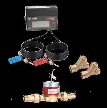
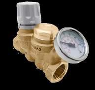
11 Key Part Number Description * Radiator valve 3 Catalog Section * Remote wall sensor AX TankMixer TM thermostatic mixing assembly 6A NA502640A PLUMBVENT TM low lead automatic air vent 6C * Radiator valve control head * Radiator connection valves A* Paddle flow switch A* Hygroscopic air vent A DISCAL air separator, rotating collar A SEP4 TM hydraulic, air, dirt, mag separator A AutoFill TM combo ASSE A* MixCal TM thermostatic mixing valve 6A NA570924* HydroFill TM water treatment unit A AutoFill TM combo ASSE E5S1A* TwistFlow TM manifold * TwisTop TM thermo-electric actuator 3 & 5 ZVR103 Z-one TM valve relay control 4 NA546306T DIRTMAG chemical kit A* FlowCal TM automatic balancing valve 6B A* Y-strainer 6B Z55P Z-one TM valve assembly A* DP bypass valve AF* FlowCal TM automatic balancing valve 6B A QuickSetter TM balancing valve 6B 6636E5A* Manifold E1AHE* Manifold mixing station 5
12 Plumbing Product Selector 1 Commercial Alternatives to LEGIOMIX motorized valve 2 recirculation return pipe hot water riser 5 check valve recirculation circulator 12 water meter 13 c w variable speed recirculation circulator return temperature sensor supply temperature sensor * supply pipe return pipe other DHW risers * * 8 9 to / from additional risers 10 Alternative to TankMixer TM 11 cold water 4 water meter supply LEGIOMIX controller & data logger * Alternatives for balancing. Key Part Number Description Catalog Section NA52367HL* High-Low mixing valve assy ASSE A A* High-flow mixing valve ASSE A A LEGIOMIX electronic mixing valve ASSE A HA Pressure reducing valve ASSE C A Anti-scald mixing valve ASSE A AC ThermoSetter TM thermal balancing valve 6B NA502640A PLUMBVENT TM low lead automatic air vent 6C AF* FlowCal TM automatic balancing valve 6B AFC QuickSetter+ TM manual balancing valve 6B 12
13 1 Plumbing Product Selector water meter cold water check valve recirculation circulator * other DHW risers * * 8 9 to / from additional risers 10 Alternative to TankMixer TM 11 water meter troller & data logger * Alternatives for balancing. Residential Key Part Number Description Catalog Section A Anti-scald mixing valve ASSE A AX TankMixer TM mixing valve assy ASSE A A MixCal TM mixing valve ASSE A HA Pressure reducing valve ASSE C A RPZ backflow preventer ASSE C 13
14
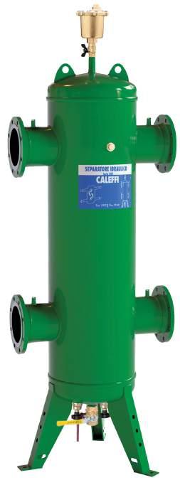
15 HYDRAULIC SEPARATORS This diagram is for illustration purposes only 1 PRODUCTS INCLUDED IN SECTION 4-in-1 hydraulic separators Hydraulic separators Hydraulic separators-manifolds Hydraulic separator accessories

. 1\" drain valve NA39753 (2\" 4\" sizes) 1¼\" drain valve NA39588 (5\" 6\" sizes). ANSI 150 flange connections. 549596A 1\" sweat union 15 1,408.")
. 549597A 1 ¼\" sweat union 19 1,716.00 549507A 1¼\" NPT female union 19 1,776.00 549567A 1¼\" press union 19 1,952.00 549552A 2\" ANSI flange 76 6,261.00 549598A 1½\" sweat union 27 2,242.")
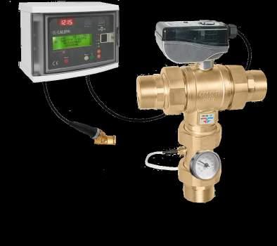
16 1 4-IN-1 HYDRAULIC SEPARATORS 5495 SEP Combination 1. air, 2. hydraulic and 3. dirt Combination 1. air, 2. hydraulic, 3. dirt separation, plus 4. magnetic separation. separation, plus 4. magnetic separation. Epoxy resin coated steel body. Epoxy resin coated steel body. HDPE internal coalescing element, Stainless steel internal coalescing mesh. removable for cleaning. Pre-formed insulation. Thermowell tap: 1/2" straight female. Working temperature range: F. Working temp. w/o insulation: F. Pre-formed insulation on 2" 4" sizes. One neodymium magnet. Complete with: automatic air vent (code A). air vent shut-off valve (code NA39589). 1" drain valve NA39753 (2" 4" sizes) 1¼" drain valve NA39588 (5" 6" sizes). ANSI 150 flange connections A 1" sweat union 15 1, A 1" NPT female union 15 1, Vessel temperature range: F. Working temp. w/o insulation: F A 1" press union 15 1, Particle separation capacity: to 5 µm (0.2 mil) A 1 ¼" sweat union 19 1, A 1¼" NPT female union 19 1, A 1¼" press union 19 1, A 2" ANSI flange 76 6, A 1½" sweat union 27 2, A 2½" ANSI flange 82 6, A 1½" NPT female union 27 2, A 3" ANSI flange 112 8, A 1½" press union 27 2, A 4" ANSI flange 120 9, A 2" sweat union 29 2, A 2" NPT female union 29 2, A 2" press union 29 2, US* 1" no tailpieces 13 1, US* 1¼" no tailpieces 17 1, US* 1½" no tailpieces 25 1, US* 2" no tailpieces 27 2, See fitting selection table in Section 8. NA549 SEP ASME Combination 1. air, 2. hydraulic and 3. dirt separation, plus 4. magnetic separation. Epoxy resin coated steel body. Stainless steel internal coalescing mesh. Three neodymium magnets. Complete with: automatic air vent (code A). air vent shut-off valve (code NA39589). drain valve (code NA59600). ANSI 150 flange connections. Thermometer pockets (NPT): ½" inlet/outlet flanges, ¾" front center Vessel temperature range: F. Particle separation capacity: to 5 µm (0.2 mil). ASME U-stamp tagged and registered with the National Board of Boiler and Pressure Vessel Inspectors; CRN registered up to 10". Consult factory for 12" 14". NA549 SEP NA549052AM 2" ANSI flange ASME & CRN 76 7, NA549062AM 2½" ANSI flange ASME & CRN 82 7, NA549082AM 3" ANSI flange ASME & CRN 112 9, NA549102AM 4" ANSI flange ASME & CRN , NA549120AM* 5" ANSI flange ASME & CRN , NA549150AM* 6" ANSI flange ASME & CRN , * without insulation NA prefix indicates ASME U-stamp tagged and registered with the National Board of Boiler and Pressure Vessel Inspectors; CRN registered. In the SEP4 hydraulic separators ferrous impurities are captured by a concentrated magnetic field created by a stack of nedimium magnetic rods, rare-earth magnets positioned inside a brass dry-well which is below the flow stream. Non-magnetic dirt particles are separated by colliding with an internal element in the flow stream and settling to the bottom. The deep collection chamber keeps the dirt from re-entering the flow stream. The dirt and ferrous impurities are flushed out even while the system is still running, by removing the magnets and opening the purge valve. FLOW RATE - UNION CONNECTIONS Size 1" 1¼" 1½" 2" GPM Gallons NA549200AM 8" ANSI flange ASME & CRN , NA549250AM 10" ANSI flange ASME & CRN , NA549300AM 12" ANSI flange ASME 1,110 52, NA549350AM 14" ANSI flange ASME 1,550 61, FLOW RATE - FLANGED CONNECTIONS Size 2" 2½" 3" 4" 5" 6" 8" 10" 12" 14" GPM Gallons

17 1 HYDRAULIC SEPARATORS 548 Hydro Separator Hydraulic separator. Epoxy resin coated steel body. 300 series stainless steel internal baffle. Pre-formed insulation. Thermowell tap: 1/2" straight female Working temperature range: F. Working temp. w/o insulation: F A 1" NPT female union 13 1, A 1" press union 13 1, A 1" sweat union 13 1, A 1¼" NPT female union 17 1, A 1¼" press union 17 1, A 1¼" sweat union 17 1, A 1½" NPT female union 25 1, A 1½" press union 25 1, A 1½" sweat union 25 1, A 2" NPT female union 27 1, A 2" press union 27 2, A 2" sweat union 27 1, US 1" no tailpieces US 1¼" no tailpieces US 1½" no tailpieces 23 1, US 2" no tailpieces 25 1, See fitting selection table in Section 8. NA548 Hydro Separator ASME Hydraulic separator. Epoxy resin coated steel body. Without insulation. Complete with: automatic air vent (code A). shut-off valve (code NA39589). drain valve (code NA59600). ANSI 150 flange connections. Thermometer pockets (NPT): ½" inlet/outlet flanges, ¾" front center Working temperature range: F. Baffle plates for all sizes: 304SST ASME U-stamp tagged and registered with the National Board of Boiler and Pressure Vessel Inspectors; Consult factory for CRN sizes 12" 14". NA548200A 8" ANSI flange ASME & CRN , NA548250A 10" ANSI flange ASME & CRN , NA548300A 12" ANSI flange ASME 1,100 33, NA548350A 14" ANSI flange ASME 1,540 53, NA548 Hydro Separator Hydraulic separator. Epoxy resin coated steel body. Pre-formed insulation on 2" 4" sizes. Complete with: automatic air vent (code A). shut-off valve (code NA39589). drain valve (code NA39588). ANSI 150 flange connections. Vessel temperature range: F. Vessel temp. w/o insulation: F. Baffle plates for all sizes: 304SST A 2" ANSI flange 75 4, A 2½" ANSI flange 82 4, A 3" ANSI flange 112 5, A 4" ANSI flange 117 6, NA548052A 2" ANSI flange ASME & CRN 75 5, NA548062A 2½" ANSI flange ASME & CRN 82 5, NA548082A 3" ANSI flange ASME & CRN 112 7, NA548102A 4" ANSI flange ASME & CRN 117 7, NA548120A* 5" ANSI flange ASME & CRN , NA548150A* 6" ANSI flange ASME & CRN , NA prefix indicates ASME U-stamp tagged and registered with the National Board of Boiler and Pressure Vessel Inspectors; CRN registered. *Without insulation NA549 HydroCal ASME Combination 1. air, 2. hydraulic and 3. dirt separation. Epoxy resin coated steel body. Stainless steel internal coalescing mesh. Pre-formed insulation on 2" 4" sizes. Complete with: automatic air vent, air vent shut-off valve, drain valve. ANSI 150 flange connections. Vessel temperature range: F. Working temp. w/o insulation: F. Particle separation capacity: to 5 μm (0.2 mil). Consult factory for CRN sizes 12" 14". NA549052A 2" ANSI flange ASME & CRN 73 7, NA549062A 2½" ANSI flange ASME & CRN 79 7, NA549082A 3" ANSI flange ASME & CRN 108 9, NA549102A 4" ANSI flange ASME & CRN 117 9, NA549120A* 5" ANSI flange ASME & CRN , NA549150A* 6" ANSI flange ASME & CRN , NA549200A* 8" ANSI flange ASME & CRN , NA549250A* 10" ANSI flange ASME & CRN , NA549300A* 12" ANSI flange ASME 1,100 52, NA549350A* 14" ANSI flange ASME 1,540 61, *Without insulation 17
 and drain valve (code 538402 FD). Max. working pressure: 100 psi. Working temperature range: 32 230 F.")


 16 1,362.00 559931A 1\" FNPT primary, 1\" MNPT secondary (4) 39 1,956.")

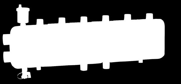
18 1 HYDRAULIC SEPARATORS-MANIFOLDS 5599 HydroLink Hydraulic separator + distribution manifold. 2+0 with built-in mounting. Steel body with pre-formed insulation. Complete with automatic air vent (code A) and drain valve (code FD). Max. working pressure: 100 psi. Working temperature range: F. Outlet center dimension: 125 mm. Compatible with 165, 166, 167 series HydroMixer HydroLink Hydraulic separator + distribution manifold. 2+2 with angle mounting brackets. Steel body with pre-formed insulation. Complete with automatic air vent (code A) and drain valve (code FD). Max. working pressure: 100 psi. Working temperature range: F. Outlet center dimension: 125 mm. Compatible with 165, 166, 167 series HydroMixer A 1" FNPT primary, 1" MNPT secondary (2) 16 1, HydroLink Hydraulic separator + distribution manifold. 2+1 with built-in mounting. Steel body with pre-formed insulation. Complete with automatic air vent (code A) and drain valve (code FD). Max. working pressure: 100 psi. Working temperature range: F. Outlet center dimension: 125 mm. Compatible with 165, 166, 167 series HydroMixer A 1" FNPT primary, 1" MNPT secondary (4) 29 1, HydroLink Hydraulic separator + distribution manifold. 3+1 with angle mounting brackets. Steel body with pre-formed insulation. Complete with automatic air vent (code A) and drain valve (code FD). Max. working pressure: 100 psi. Working temperature range: F. Outlet center dimension: 125 mm. Compatible with 165, 166, 167 series HydroMixer A 1" FNPT primary, 1" MNPT secondary (3) 16 1, A 1" FNPT primary, 1" MNPT secondary (4) 39 1, Secondary Application diagram Primary Secondary Maximum recommended flow rates at connections: Branches Primary Secondary Total gpm 22 gpm gpm 22 gpm gpm 26 gpm gpm 26 gpm 18


19 1 HYDRAULIC SEPARATOR ACCESSORIES 501 MAXCAL TM Replacement air vent for Hydro Separator Fits NA548 Series and NA549 Series. Brass body and cover, stainless steel internal components. Extra high discharge capacity. Max. working pressure: 230 psi. Max. discharge pressure: 90 psi. Max. working temperature: 250 F. Discharge top thread: 3 /8 " female. Drain ball valves fit HydroCal, Hydro Separators, DISCAL, DISCALDIRT and DIRTCAL. Brass body. Max. working temperature: 365 F A ¾" FNPT MINICAL TM Replacement high capacity air vent for 5599 HydroLink. Automatic air vents. Brass body. Hygroscopic safety air vent cap. Max discharge pressure: 60 psi. Max. working temperature: 250 F. NA39589 ¾" FNPT w/t-handle, air vent isolate NA " FNPT w/lever, drain NA ¼" FNPT w/lever, drain NA " FNPT w/lever, drain Temperature pocket well fits 1", 1¼", 1½" & 2" 548 / 5495 Hydro Separators. 1 ¾" pocket length. Inside thread: 20 x1.0 mm A ½" MNPT VALCAL TM Replacement high capacity air vent with service check valve fits Hydro Separator 548 series. Brass body. Max. discharge pressure: 60 psi. Max. working temperature: 250 F ½" straight thread F50055 Sealing washer NA10426 Sensor holding grommet NA10425 Kit containing above 3 items Double male nipple. R41447 ¾" NPT x ¾" NPT x 2" A ½" MNPT Replacement drain valve fits Hydro Separator 548 series and HydroLink 559 series. Brass body. ¾ garden hose thread with cap. Max. working temperature: 250 F FD ½" NPT x ¾" GHT Magnetic/drywell assembly for SEP4. F Fits 2" and 2½" A Fits 3" 6" F Fits 8" to 14"
20 20 1
21 AIR AND DIRT SEPARATION AND AIR VENTS This diagram is for illustration purposes only 2 VENT PRODUCTS INCLUDED IN SECTION Automatic and manual air vents Air separators Dirt separators Air and dirt separators Dirt and magnetic dirt separators Magnetic dirt separators Accessories for air and dirt separators
22 2 AUTOMATIC AND MANUAL AIR VENTS Automatic air vents are designed to remove the air that accumulates in heating and cooling systems without the need for manual intervention. This prevents harmful air that may compromise the life and the performance of the system which includes: corrosion due to the oxygen; pockets of air trapped in the heat emitters; cavitation in the circulation pumps; noise from air passing through the pipes. The accumulation of air bubbles in the air vent body causes the float to drop and thus the vent valve to open. The air vent functions correctly, as long as the water pressure remains below the maximum discharge pressure. MAXCAL TM Extra high capacity air vent is ideal for use in large piping systems and can also be installed in horizontal piping. The valve body and cover are made of forged brass while the filter, valve stem, float, and spring are all made of stainless steel to prevent the formation of rust. 501 MAXCAL Automatic air vent for heating and air conditioning. Brass body and cover, stainless steel internal components. Extra high discharge capacity. Max. working pressure: 230 psi. Max. discharge pressure: 90 psi. Max. discharge rate: 9 SCFM. Working temperature range: F. Discharge top thread: 3 /8 " female A ¾" FNPT MINICAL TM and VALCAL TM These float type automatic air vents are designed to vent released air from the water while being heated. They are used on manifolds or pipes in sealed heating systems. MINICAL TM is a standard size air vent that will discharge up to 1.75 SCFM. VALCAL TM is a high capacity larger size air vent that will discharge up to 2.5 SCFM. Some MINICAL TM and VALCAL TM models are equipped with a hygroscopic safety cap. Cellulose fiber discs serve as the redundant seal. Their volume increases by 50% when they become wet which cause the discharge vent to close. Some MINICAL TM and VALCAL TM models are equipped with a service check valve which facilitates maintenance operations by shutting off the water flow when the air vent is removed and also allows an easy replacement of air vent without purging the system MINICAL Automatic air vent. Brass body. Max. discharge pressure: 40 psi. Max. discharge rate: 1.75 SCFM. Max. working temperature: 250 F A 1 /8" MNPT A ½" MNPT MINICAL Automatic air vent with service check valve Brass body. Max. discharge pressure: 40 psi. Max. discharge rate: 1.75 SCFM. Max. working temperature: 230 F A 1 /8" MNPT A 1 /8" MNPT, hygroscopic anti-drip cap MINICAL Automatic air vent. Brass body. Hygroscopic safety air vent cap. Max discharge pressure: 60 psi. Max. discharge rate: 1.75 SCFM. Max. working temperature: 250 F A ½" MNPT VALCAL High discharge automatic air vent. Brass body. Max. discharge pressure: 60 psi. Max. discharge rate: 2.5 SCFM. Max. working temperature: 250 F A ½" MNPT VALCAL High discharge vent with service check. Brass body. Max. discharge pressure: 60 psi. Max. discharge rate: 2.5 SCFM. Max. working temperature: 250 F A ½" MNPT
23 2 AUTOMATIC AND MANUAL AIR VENTS 5026 ROBOCAL Automatic air vent. Brass body. Max. discharge pressure: 90 psi. Max. discharge rate: 1.75 SCFM. Max. working temperature: 240 F A 1 /8" MNPT A ¼" MNPT /8" straight thread ½" straight thread ROBOCAL Automatic air vent with service check valve. Brass body. Max. discharge pressure: 90 psi. Max. discharge rate: 1.75 SCFM. Max. working temperature: 240 F A 1 /8" MNPT A ¼" MNPT NA502740A ½" MNPT, hygroscopic anti-drip cap HYGROCAL Automatic hygroscopic air vent for hydronic heating system and low pressure steam. Manual operation by rotating knob. Chrome plated brass body. Max. working temperature: 212 F. Low pressure steam: 15 psi. (Priced each, sold in package of 25 each) A 1 /8" MNPT Automatic radiator air vent valve is designed to remove any air trapped inside the heat emitters both during the filling of the system and in normal operation. The automatic air discharge happens when the hygroscopic cellulose fiber discs are dry. As air is vented and water contacts the hygroscopic discs, they increase their volume by 50% which cause the discharge vent to close Replacement hygroscopic cartridge fits hygroscopic air vent 5080 series. (Priced each, sold in package of 25 each) Service check valve for removal of air vent or expansion tank without purging system. Fits automatic air vents 502 series. Max. working temperature: 250 F A 1 /8" MNPT x FNPT A ¼" MNPT x FNPT A ½" MNPT x FNPT A Cartridge Manual air vent with metal seal and adjustable outlet. Brass body. Max. working temperature: 212 F. 551 DISCAL High discharge automatic air vent. Brass body. Stainless steel float guide pin and linkage. Max. discharge pressure: 150 psi. Max. discharge rate: 4.5 SCFM. Max. working temperature: 250 F A ½" FNPT A ¼" MNPT Function DISCALAIR automatic air vents release air that forms in the hydraulic circuits of heating and air conditioning systems with pressures to 150 psi. The venting air discharge capacity is capable of expelling over 4 standard cubic feet per minute (SCFM). The circulation of fully de-aerated water or glycol-water mediums enables the equipment to operate under optimum conditions, free from noise, corrosion, localized overheating, or mechanical damage. 23
 to mount expansion tank on bottom thread. Brass body.")

 to mount expansion tank on bottom thread. Brass body. Stainless steel float guide pin and linkage.")

 to mount expansion tank on bottom thread. Brass body. Stainless steel float guide pin and linkage.")
24 2 AIR SEPARATORS 551 DISCAL Sweat Air separator. Brass body. Stainless steel float guide pin and linkage. Glass reinforced nylon internal element. ½" NPT female bottom thread. Working temperature range: F. 551 DISCAL Sweat Air separator with ½" service check valve (code A) to mount expansion tank on bottom thread. Brass body. Stainless steel float guide pin and linkage. Glass reinforced nylon internal element. Working temperature range: F A 1" sweat A 1¼" sweat A 1½" sweat A 2" sweat DISCAL NPT Air separator. Brass body. Stainless steel float guide pin and linkage. Glass reinforced nylon internal element. ½" NPT female bottom thread. Working temperature range: F AC 1" sweat AC 1¼" sweat AC 1½" sweat AC 2" sweat DISCAL NPT Air separator with automatic ½" check valve (code A) to mount expansion tank on bottom thread. Brass body. Stainless steel float guide pin and linkage. Glass reinforced nylon internal element. Working temperature range: F A ¾" FNPT A 1" FNPT A 1¼" FNPT A 1½" FNPT A 2" FNPT DISCAL Press Air separator. Brass body. Stainless steel float guide pin and linkage. Glass reinforced nylon internal element. Working temperature range: F AC ¾" FNPT AC 1" FNPT AC 1¼" FNPT AC 1½" FNPT AC 2" FNPT DISCAL Press Air separator with automatic ½" check valve (code A) to mount expansion tank on bottom thread. Brass body. Stainless steel float guide pin and linkage. Glass reinforced nylon internal element. Working temperature range: F A 1" integral press A 1¼" integral press A 1½" integral press A 2" integral press AC 1" integral press AC 1¼" integral press AC 1½" integral press AC 2" integral press


25 2 AIR SEPARATORS Construction details The air separator uses the combined action of several physical principles. The active part consists of an assembly of concentric mesh surfaces. These elements create the whirling movement required to facilitate the release of microbubbles and their adhesion to these surfaces. The bubbles, fusing with each other, increase in size until the hydrostatic thrust overcomes the adhesion force to the mesh. They rise towards the top of the unit from which they are released through a float-operated automatic air vent with stainless steel float guide pin, which keeps the float from binding. 551 DISCAL Compact Air separator. Brass body. Stainless steel float guide pin and linkage. Stainless steel mesh internal element. ½" NPT bottom thread. Working temperature range: F. LINKAGE FLOAT FLOAT GUIDE PIN COALESCING MESH A ¾" FNPT A ¾" sweat LARGE DIAMETER CHAMBER OPTIONAL CHECK VALVE ½ NPT MAXIMUM FLOW RATE Size ¾" 1" 1¼" 1½" 2" GPM Cv DISCAL Compact Air separator with ½" service check valve to mount expansion tank on bottom thread. Brass body. Stainless steel float guide pin and linkage. Stainless steel mesh internal element. Working temperature range: F. MAXIMUM FLOW RATE Size ¾" compact ¾" vertical 1" vertical GPM Cv ACCESSORIES Service check valve for easy replacement of expansion tank when connected to bottom of DISCAL A ½" MNPT x ½" FNPT AC ¾" FNPT AC ¾" sweat DISCAL Rotating collar Air separator with rotating collar for horizontal or vertical pipes. Brass body. Stainless steel float guide pin and linkage. Stainless steel mesh internal element. Working temperature range: F. Insulation shell fits DISCAL 551 series. CBN Fits ¾"* and 1" 551 series CBN Fits 1¼" and 1½" 551 series CBN Fits 2" 551 series *Will not fit the ¾" compact DISCAL ; codes A and A A 3/4" NPT male union A 3/4" press union A 3/4" sweat union A 1" NPT male union A 1" press union A 1" sweat union * body only, order unions separately *See fitting selection table in Section 8. 25
. ½\" NPT male side drain connection. Complete with side drain valve (538402FD). Vessel temperature range: 32 270 F.")
. ½\" NPT male side drain connection. Complete with side drain valve (538402FD). Vessel temperature range: 32 270 F.")

26 2 AIR SEPARATORS 551 DISCAL Air separator. Epoxy resin coated steel body. Stainless steel float guide pin and linkage. Stainless steel mesh internal element. ANSI 150 flange connections. 1" NPT male bottom drain connection. Complete with male bottom drain valve (NA39753). ½" NPT male side drain connection. Complete with side drain valve (538402FD). Vessel temperature range: F. NA551 DISCAL ASME/CRN Air separator. Epoxy resin coated steel body. Stainless steel float guide pin and linkage. Stainless steel mesh internal element. ANSI 150 flange connections. 1" NPT male bottom drain connection. Complete with drain valve (NA39753). ½" NPT male side drain connection. Complete with side drain valve (538402FD). Vessel temperature range: F. ASME and CRN registered A 2" ANSI flange 34 3, AT 2" MNPT 30 3, Air separator construction A 2½" ANSI flange 35 3, AT 2½" MNPT 31 3, A 3" ANSI flange 62 4, A 4" ANSI flange 67 5, A 5" ANSI flange 106 7, A 6" ANSI flange 117 9, DISCAL air separators are constructed to allow maintenance and cleaning operations to be carried out without having to remove the separator body from the pipe work. All DISCAL air separator have a bottom connection drain valve. All internal air release control components are fully accessible. The automatic air release valve, located at the top of the separator, has a long chamber for the movement of the float. This feature prevents any debris present in the water from reaching the sealing seat. Flanged models include a side drain vent to release large amounts of air when filling the system and to remove any debris present above the water level. NA551050A 2" ANSI flange ASME & CRN 34 3, NA551060A 2½" ANSI flange ASME & CRN 35 4, NA551080A 3" ANSI flange ASME & CRN 62 5, NA551100A 4" ANSI flange ASME & CRN 67 6, NA551120A 5" ANSI flange ASME & CRN 106 8, NA551150A 6" ANSI flange ASME & CRN , NA prefix indicates ASME tagged and registered with the National Board of Boiler and Pressure Vessel Inspectors; CRN registered. NA551 DISCAL ASME Air separator. Epoxy resin coated steel body. Stainless steel float guide pin and linkage. Stainless steel mesh internal element. ANSI 150 flange connections. 2" NPT male bottom drain connection. Complete with drain valve (NA59600). ½" NPT male side drain connection. Complete with side drain valve (538402FD). Vessel temperature range: F. ASME registered. Consult factory for CRN on 12" only. NA551200A 8" ANSI flange ASME & CRN , NA551250A 10" ANSI flange ASME & CRN , NA551300A 12" ANSI flange ASME , NA prefix indicates ASME tagged and registered with the National Board of Boiler and Pressure Vessel Inspectors; CRN registered. MAXIMUM FLOW RATE Size 2" 2½" 3" 4" 5" 6" 8" 10" 12" GPM ,570 2,450 3,525 Cv ,109 1,387 1,664 Replacement drain ball valve. Fits DISCAL series. Brass body. Lever. Max. working temperature: 365 F. NA " FNPT with lever NA " FNPT with lever
27 2 DIRT SEPARATORS The dirt separating action performed by the DIRTCAL is based on using the internal element with concentric diamond pattern mesh surfaces instead of a mechanical filter. The element offers little resistance to the medium flow while ensuring dirt separation. This occurs due to the particles colliding with the concentric diamond pattern mesh surfaces and then settling to the bottom, and not by filtration; which, over time, gets continuously clogged. By contrast, the DIRTCAL low-velocity zone dirtseparator efficiently removes the particles to as small as 5 µm (0.2 mil) with very low head loss. The dirt collection chamber at the bottom of the DIRTCAL is at the optimal distance from the inlet and outlet connections to ensure that the collected dirt particles are not affected by the swirling flow through the mesh element. The dirt can then be removed through the bottom drain port even with the system running, by opening the drain valve. Low head losses and performance are maintained over time Dirt separator. Epoxy resin coated steel body. 1" threaded NPT bottom drain connection Complete with drain valve (code NA39753). ¾" NPT male top thread with brass cap. ANSI 150 flange connections. Vessel temperature range: F. Particle separation capacity: to 5 µm (0.2 mil) A 2½" ANSI flange 38 2, Dirt separation comparison MAGNETITE (Working Range) RUST SAND WELDING RESIDUE average diameter of particles [μm] Y-strainers (Working Range) NA5465 ASME/CRN Dirt separator. Epoxy resin coated steel body. 1" threaded NPT bottom drain connection Complete with drain valve (code NA39753). ¾" NPT male top thread with brass cap. ANSI 150 flange connections. Vessel temperature range: F. Particle separation capacity: to 5 µm (0.2 mil). ASME and CRN registered. NA546550A 2" ANSI flange ASME & CRN 38 3, NA546560A 2½" ANSI flange ASME & CRN 38 3, NA546580A 3" ANSI flange ASME & CRN 55 4, NA546510A 4" ANSI flange ASME & CRN 55 5, NA546512A 5" ANSI flange ASME & CRN 138 7, NA546515A 6" ANSI flange ASME & CRN 148 9, ASME U-stamp tagged and registered with the National Board of Boiler and Pressure Vessel Inspectors CRN registered. NA5465 Dirt separator. Epoxy resin coated steel body. 2" threaded NPT bottom drain connection. Complete with drain valve (code NA59600). ¾" NPT male top thread with brass cap. ANSI 150 flange connections. Vessel temperature range: F. Particle separation capacity: to 5 µm (0.2 mil). ASME and CRN registered. For CRN consult factory for sizes 12" 14". MAXIMUM FLOW RATE ASME/CRN NA546520A 8" ANSI flange ASME & CRN , NA546525A 10" ANSI flange ASME & CRN , NA546530A 12" ANSI flange ASME , NA546535A 14" ANSI flange ASME 1,000 45, ASME U-stamp tagged and registered with the National Board of Boiler and Pressure Vessel Inspectors registered. CRN registered, 8" and 10"; consult factory for 12" 14". Size 2" 2½" 3" 4" 5" 6" GPM Cv MAXIMUM FLOW RATE Size 8" 10" 12" 14" GPM 1,570 2,450 3,525 4,800 Cv 1,055 1,400 1,755 2,075 27

28 2 AIR AND DIRT SEPARATORS The DISCALDIRT air and dirt separator uses a coalescing element that consists of an assembly of concentric diamond pattern mesh surfaces. This element creates the whirling movement required to facilitate the release of micro-bubbles and their adhesion to these surfaces. The bubbles, fusing with each other, increase in volume until the bouyancy force overcomes the adhesion force to the surface. They rise towards the top of the unit and are released through a float-operated automatic air release valve. The dirt separating action performed by the same element offers little resistance to the medium flow while ensuring dirt separation. The particles collide with the concentric diamond pattern mesh surfaces and then settle to the bottom, and not by filtration unlike mesh strainers; which, over time, get progressively clogged. By contrast, the DISCALDIRT s low-velocity zone dirt separator function efficiently removes the particles to as small as 5µm (0.2 mil) with very low head loss. The dirt can then be removed through the bottom drain port. 546 DISCAL Air & Dirt separator. Brass body. Stainless steel float guide pin and linkage. Glass reinforced nylon internal element. Working temperature range: F. Particle separation capacity: to 5 µm (0.2 mil) DISCAL Air & Dirt separator with magnet. Epoxy resin coated steel body. Stainless steel float guide pin and linkage. Stainless steel mesh internal element. Complete with union connections. Working temperature range: F Particle separation capacity: to 5 µm (0.2 mil). Ferrous impurities separation efficiency: 100% A 1½" sweat union 22 1, A 1½" NPT female union 22 1, A 1½" press union 22 2, A 2" sweat union 23 1, A 2" NPT female union 23 2, A 2" press union 23 2, Insulation shell for DISCALDIRT & DISCALDIRTMAG TM A 1" sweat A 1" MNPT A 1¼" sweat CBN Fits 1", 1¼" brass 546 only CBN Fits 1½" steel 5461 only CBN Fits 2" steel 5461 only The DISCALDIRTMAG air and dirt separator with magnet uses an external magnet ring for separation of ferrous impurities. The external magnet allows greater effectiveness in the separation and collection of ferrous impurities. The impurities are retained in the body of the dirt separator by the strong magnetic field created by magnets in its external outer ring. The outer ring is removable from the body to allow the flushing of sludge, with the system still running. Since the magnetic ring is positioned outside the body of the dirt separator, it does not interfere with the flow through the device DISCAL Air & Dirt separator with magnet. Brass body. Stainless steel float guide pin and linkage. Glass reinforced nylon internal element. Working temperature range: F. Particle separation capacity: to 5 µm (0.2 mil). Ferrous impurities separation efficiency: 100% A 1" sweat A 1" MNPT A 1¼" sweat MAXIMUM FLOW RATE Size 1" 1¼" 1½" 2" GPM Cv DISCAL Air & Dirt separator. Epoxy resin coated steel body. Stainless steel float guide pin and linkage. Stainless steel mesh internal element. 1" NPT threaded bottom drain connection. Complete with side drain valve ( FD). ANSI 150 flange connections. Complete with drain valve (NA39753) Vessel temperature range: F. Particle separation capacity: to 5 µm (0.2 mil) A 2" ANSI flange 40 4, A 2½" ANSI flange 42 4, A 3" ANSI flange 73 5, A 4" ANSI flange 78 6, A 5" ANSI flange 181 8, A 6" ANSI flange ,
 and 2\" (8 14\" sizes) threaded NPT bottom drain connection. ANSI 150 flange connections. Complete with drain valve NA39753 (2 6\" sizes), NA59600 (8 14\" sizes).")

29 2 AIR AND DIRT SEPARATORS NA546 DISCAL ASME/CRN Air & Dirt separator. Epoxy resin coated steel body. Stainless steel float guide pin and linkage. Stainless steel mesh internal element. 1" (2 6" sizes) and 2" (8 14" sizes) threaded NPT bottom drain connection. ANSI 150 flange connections. Complete with drain valve NA39753 (2 6" sizes), NA59600 (8 14" sizes). Vessel temperature range: F. ASME and CRN registered. For CRN consult factory for factory sizes 12-14". NA546050T 2" Threaded ASME & CRN 28 3, NA546060A 2½" ANSI flange ASME & CRN 42 5, NA546080A 3" ANSI flange ASME & CRN 73 6, NA546100A 4" ANSI flange ASME & CRN 78 7, NA546120A 5" ANSI flange ASME & CRN , NA546150A 6" ANSI flange ASME & CRN , NA546200A 8" ANSI flange ASME & CRN , NA546250A 10" ANSI flange ASME & CRN , NA546300A 12" ANSI flange ASME , NA546350A 14" ANSI flange ASME , ASME U-stamp tagged and registered with the National Board of Boiler and Pressure Vessel Inspectors; CRN registered, 2" 10"; consult factory for 12" 14". Low head losses and high performance are maintained over time. The dirt separating action performed by the DISCALDIRT air and dirt separator is based on using the internal element with concentric diamond pattern mesh 1 1 surfaces instead of an ordinary filter. The element offers little resistance to the medium flow while ensuring dirt separation. This occurs due to the particles colliding with the concentric diamond pattern mesh surfaces and then settling to the bottom, and not by filtration; which, over time, gets progressively 2 clogged. By contrast, 2 the DISCALDIRT low-velocity zone air and dirt separator efficiently removes the particles to as small 3 3 as 5 μm (0.2 mil) with very low head loss. The dirt collection chamber at the bottom of the DISCALDIRT is at the right distance from the inlet and outlet connections so that the collected dirt particles are not affected by the swirling flow through the bottom drain port, even with the system running, by opening the drain valve with the handle. COALESCING MESH NA546M DISCAL ASME/CRN Air & Dirt separator with magnets. Epoxy resin coated steel body. Stainless steel float guide pin and linkage. Stainless steel mesh internal element. ANSI 150 flange connections. 1" (2 6" sizes) and 2" (8 14" sizes) threaded NPT bottom drain connection. Complete with drain valve NA39753 (2 6" sizes), NA59600 (8 14" sizes). Vessel temperature range: F. Particle separation capacity: to 5 µm (0.2 mil). Ferrous impurities separation efficiency: 100%. ASME and CRN registered. For CRN consult factory for factory sizes 12-14". NA546050TM* 2" Threaded ASME & CRN 31 4, NA546060AM* 2½" ANSI flange ASME & CRN 45 5, NA546080AM* 3" ANSI flange ASME & CRN 76 7, NA546100AM* 4" ANSI flange ASME & CRN 81 8, NA546120AM* 5" ANSI flange ASME & CRN , NA546150AM* 6" ANSI flange ASME & CRN , NA546200AM** 8" ANSI flange ASME & CRN , NA546250AM** 10" ANSI flange ASME & CRN , NA546300AM** 12" ANSI flange ASME , NA546350AM** 14" ANSI flange ASME , *with one magnet **with three magnets ASME U-stamp tagged and registered with the National Board of Boiler and Pressure Vessel Inspectors. CRN registered, 2" 10"; consult factory for 12" 14". In the DISCALDIRTMAG TM air and dirt separator with magnets ferrous impurities are captured by a concentrated magnetic field created by a stack of neodymium rare-earth magnets positioned inside a brass dry-well which is below the flow stream. Non-magnetic dirt particles are separated by colliding with an internal element in the flow stream and settling to the bottom. The deep collection chamber keeps the dirt from reentering the flow stream. The dirt and ferrous impurities are flushed out while the system is operating, by removing the magnets and opening the purge valve. NA546 LARGE DIAMETER DIRT COLLECTION CHAMBER DRAIN VALVE HANDLE NA546M MAGNETS MAXIMUM FLOW RATE Size 2" 2½" 3" 4" 5" 6" 8" 10" 12" 14" GPM ,570 2,450 3,525 4,800 Cv ,109 1,387 1,664 1,967 29


30 2 DIRT & MAGNETIC DIRT SEPARATORS The dirt separating action performed by the DIRTCAL is based on using the internal element with concentric diamond pattern mesh surfaces instead of a mechanical filter. The element offers little resistance to the medium flow while ensuring dirt separation. This occurs due to the particles colliding with the concentric diamond pattern mesh surfaces and then settling to the bottom, and not by filtration; which, over time, gets continuously clogged. By contrast, the DIRTCAL low-velocity zone dirt separator requires a pressure drop 25% or less than that of a comparable Y-strainer depending on mesh size and amount of filtered debris. It efficiently removes the particles to as small as 5 µm (0.2 mil) with very low head loss. The dirt collection chamber at the bottom of the DIRTCAL is at the optimal distance from the inlet and outlet connections to ensure that the collected dirt particles are not affected by the swirling flow through the mesh element. The dirt can then be removed through the bottom drain port even with the system running by opening the drain valve. Low head losses and performance are maintained over time Dirt separator. Brass body. ½" NPT top thread with plug for optional air vent, code A. Working temperature range: F. Particle separation capacity: to 5 µm (0.2 mil) A ¾" FNPT A 1" sweat A 1" FNPT A 1" press A 1¼" sweat A 1¼" FNPT A 1¼" press A 1½" sweat A 1½" FNPT A 2" sweat A 2" FNPT Replacement drain valve fits DIRTCAL 5462 series, DIRTMAG 5463 series, DISCALDIRT 546 series and DISCALDIRTMAG TM 5461 series. Brass body. Max. working temperature: 250 F FD ½" MNPT x ¾" GHT The versatile DIRTMAG magnetic dirt separator removes both magnetic and non-magnetic particles continuously. In addition to removing sand and rust impurities with a glass-reinforced nylon internal element in a low-velocity zone chamber, the DIRTMAG features a powerful removable external magnet around the body below the flow line for fast and effective capture of ferrous particles. The DIRTMAG has the magnet positioned externally to maintain low pressure loss, and removes up to 100% of the ferrous impurities that can form in a hydronic system. The DIRTMAG can be fitted with optional insulated covers, code CBN5462xx series purchased separately, to minimize heat loss Dirt separator with magnet. Brass body. ½" NPT top thread with plug. Working temperature range: F. Particle separation capacity: to 5 µm (0.2 mil). Ferrous impurities separation efficiency: 100% A 1" sweat A 1" FNPT A 1" press A 1¼" sweat A 1¼" FNPT A 1¼" press A 1½" sweat A 1½" FNPT A 1½" press A 2" sweat A 2" FNPT A 2" press Insulation shell fits DIRTCAL 5462 and DIRTMAG 5463 series. Labels included for field installation to externally identify product use. DIRTCAL to DIRTMAG Retrofit kit. F41661A Retrofit kit CBN Fits ¾" & 1" DIRTCAL, DIRTMAG CBN Fits 1¼" & 1½" DIRTCAL, DIRTMAG CBN Fits 2" DIRTCAL, DIRTMAG


.")


31 VENT 2 MAGNETIC DIRT SEPARATORS NA5463 Chemical kit Magnetic Dirt separator plus Boiler Chemical Treatment Kit. Brass body. ½" NPT top thread with plug. Treats up to 30 gallons. DIRTMAG plus 1 can of Rhomar Hydro-Solv TM cleaner and 1 can of Pro-Tek treatment. Aerosols are injected into the hydronic system through the GHT connection on the bottom of the DIRTMAG. NA5453 Dirt separator with magnet. Brass mounting housing. Composite PA66G30 body. Max. working pressure: 45 psi. Working temperature range: F. Particle separation capacity: to 5 µm (0.2 mil). Ferrous impurities separation efficiency: 100%. Drain valve with hose connection. Top dosing point port. Dosing capacity: 12 fluid oz. Manual screw air vent. NA546328T 1" sweat NA546306T 1" FNPT NA546366T 1" press NA546335T 1¼" sweat NA546307T 1¼" FNPT NA546367T 1¼" press Construction SERVICEABLE MESH NA ¾" NPT male union NA ¾" press union NA ¾" sweat union NA " NPT male union NA " press union NA " sweat union NA ¾" NPT female union, isolation valves NA " NPT female union, isolation valves NA " press union, isolation valves Application LARGE CHAMBER AEROSOL CAN INJECTION CAP MAGNET CHEMICALS DRAIN VALVE WITH GHT FOR AEROSOL INJECTION MAXIMUM FLOW RATE Size ¾" 1" GPM Cv w/ ball valve 9 9 Cv w/o ball valve The dirt separator with magnet combines the action of the internal element and magnet. The impurities in the water strike the internal element and are separated, dropping into the bottom of the body where they are collected. Ferrous impurities are also trapped inside the dirt separator body by two strong magnets inserted into removable outer ring collar. The collected impurities are discharged by removing the external ring magnet and opening the drain valve. This procedure can be performed while the system is in operation. Rhomar cleaner used to clean/flush system prior to commissioning, Rhomar inhibitor added after fill/purge process. Not permanently connected. The special coupling between the locking nut and the mounting base allows the DIRTMAG dirt separator to be rotated for installation to either vertical or horizontal pipes, while maintaining the same operating performance. 31


. ¾\" NPT male top thread with brass cap. ANSI 150 flange connections.")

. Ferrous impurities separation efficiency: 100%. ASME registered. CRN registered up to 10\". Consult factory for 12\" and 14\".")
32 2 MAGNETIC DIRT SEPARATORS Ferrous and non ferrous impurities in hydronic systems can deposit onto heat exchanger surfaces and accumulate in pump cavities causing reduced thermal efficiency and premature wear. The small and often microscopic magnetic particles, called magnetite, form when iron or steel corrodes. Highly abrasive, the extremely fine particles are difficult to remove by traditional means. DIRTMAG separators offer highly efficient separation of typical dirt as well as magnetite. The magnetite is captured by a concentrated magnetic field created by a stack of neodymium rare-earth magnets positioned inside a brass dry-well which is below the flow stream. Non-magnetic dirt particles are separated by colliding with an internal element in the flow stream, settling to the bottom. The deep collection chamber keeps the dirt from re-entering the flow stream. 5465M Magnetic dirt separator. Epoxy resin coated steel body. Complete with drain valve (code NA39753). ¾" NPT male top thread with brass cap. ANSI 150 flange connections. Vessel temperature range: F. Particle separation capacity: to 5 µm (0.2 mil). Ferrous impurities separation efficiency: 100% AM 2" ANSI flange 41 2, AM 2½" ANSI flange 41 2, AM 3" ANSI flange 58 3, AM 4" ANSI flange 58 4, NA5465M ASME/CRN Magnetic dirt separator with one magnet assembly. Epoxy resin coated steel body. Complete with drain valve (code NA39753). ¾" NPT male top thread with brass cap. ANSI 150 flange connections. Vessel temperature range: F. Particle separation capacity: to 5 µm (0.2 mil). Ferrous impurities separation efficiency: 100%. ASME registered. CRN registered up to 10". Consult factory for 12" and 14". To purge the debris, the flexible magnetic stack is removed from the brass dry-well and, even while the system is still running, the drain valve is opened. Aided by the system pressure, the dirt and magnetite flushes out quickly and effectively. DIRTMAG magnetic dirt separators accomplish 2½ times the ferrous impurities removal performance of standard dirt separators, delivering up to 100% elimination efficiency. MAXIMUM FLOW RATE Size 2" 2½" 3" 4" 5" 6" GPM Cv MAXIMUM FLOW RATE Size 8" 10" 12" 14" GPM 1,570 2,450 3,525 4,800 Cv 1,055 1,400 1,755 2,075 NA546550AM 2" ANSI flange ASME & CRN 41 3, NA546560AM 2½" ANSI flange ASME & CRN 41 3, NA546580AM 3" ANSI flange ASME & CRN 58 5, NA546510AM 4" ANSI flange ASME & CRN 58 5, NA546512AM 5" ANSI flange ASME & CRN 141 7, NA546515AM 6" ANSI flange ASME & CRN 151 9, NA5465M ASME/CRN Magnetic dirt separator with three magnets assembly. Epoxy resin coated steel body. Complete with drain valve (code NA59600). ¾" NPT male top thread with brass cap. ANSI 150 flange connections. Vessel temperature range: F. Particle separation capacity: to 5 µm (0.2 mil). Ferrous impurities separation efficiency: 100%. ASME registered. CRN registered, 8" 10". Consult factory for 12" 14". NA546520AM 8" ANSI flange ASME & CRN , NA546525AM 10" ANSI flange ASME & CRN , NA546530AM 12" ANSI flange ASME , NA546535AM 14" ANSI flange ASME 1,010 48,
, brass 546, brass and steel 5461 series and SEP4 TM 5495 series. R59681 Vent cap 0.1 26.")
33 2 ACCESSORIES FOR AIR AND DIRT SEPARATORS Hygroscopic air vent cap fits DISCAL 551, and DISCALDIRT 546 series, and MINICAL 502 series. Replacement air vent assembly fits DISCAL brass 551 series (except Compact and Rotating Collar version), brass 546, brass and steel 5461 series and SEP4 TM 5495 series. R59681 Vent cap Anti-suction air vent cap fits DISCAL 551, DISCALDIRT 546 series and MINICAL 502 series Air Vent Replacement air vent assembly fits steel 551, NA551 steel DISCAL and 546 steel series DISCAL DIRT and DISCALDIRTMAG TM Vent cap Replacement air vent cap fits DISCAL 551 and DISCALDIRT 546 series Air vent Replacement cover and float fits DISCAL brass 551 series and DISCALDIRT brass 546 series. Vent cap sold separately. R59119 Vent cap Replacement plastic cap fits MINICAL 5020 and 5021 series. R56214 Vent cap Replacement plastic air vent cap fits 5026 and 5027 series. F39807 Cover and float Drain ball valve. Fits DIRTCAL 5465 and NA5465 series. Fits steel separators in section 2. Brass body. Lever. Max. working temperature: 365 F. NA " FNPT with lever NA " FNPT with lever Vent cap adapter fits all air separators and air vents except 5026 and 5027 series R56142 Vent cap Magnetic/drywell assembly for DISCALDIRTMAG TM and DIRTMAG NA10204 ¼" MNPT Vent cap adapter NA10204 replaces the air vent cap, provides a ¼" male NPT thread which can be used to connect a discharge tube with separate fittings A Fit 2" and 2½" A Fit 3" to 6" F Fit 8" to 14"
34 34 2
35 VENT THERMOSTATIC RADIATOR VALVES This diagram is for illustration purposes only 3 PRODUCTS INCLUDED IN SECTION Thermostatic control heads Accessories for thermostatic control heads Thermo-electric actuators NPT thermostatic radiator valve bodies European towel warmer radiator valves Connection valves for panel radiators Connection fittings
. 200000 Built-in sensor 0.5 82.80 201 Thermostatic control head fits radiator valves.")
.")
. Capillary length: 78\" (2 m).")
36 3 THERMOSTATIC CONTROL HEADS 200 Thermostatic control head fits radiator valves. Set point locking mechanism. Range stop adjustment. Built-in sensor with liquid-filled element. Fits valve 220, 221, 338 and 339 series. Graduated scale from * to 5 corresponding to a temperature scale adjustment range of 45 82ºF (7 28ºC) Built-in sensor Thermostatic control head fits radiator valves. With remote sensor. Fits valve 220, 221, 338 and 339 series. Graduated scale from * to 5 corresponding to a temperature scale adjustment range of 45 82ºF (7 28ºC). Capillary length: 78" (2 m) Remote sensor Thermostatic control head with remote adjusting knob, liquid-filled element. Fits valves 220, 221, 338, 339 & 676 series (direct coupling). Temperature range: F (6 28 C). Capillary length: 78 in. (2 m.) Remote wall sensor Thermostatic control head fits radiator valves; with contact probe. Built-in sensor with liquid-filled element. Fits valve 220, 221, 338 and 339 series. The pre-set scale corresponds to adjustment temperature range of ºF (20 50ºC). Capillary length: 78" (2 m) Remote sensor probe ACCESSORIES 4490 Manual knob for thermostatic radiator valves. Fits valves 220 and 221 series Manual knob Key features The thermostatic control head is filled with a non compressible liquid bellows (1). Plus, the radiator valve body has an extra strong valve stem compression spring (2). The non compressible liquid provides the force required to compress the strong valve stem spring. When the temperature decreases, the liquid bellows contracts, which allows the valve stem spring to lift the valve plug from valve seat after long periods of non-movement. This ensures that after a long off-season, when the actuator operates for the first time, the spring reliably lifts the valve plug off the seat without sticking. In addition, the control head features an easyto-use locking mechanism that prevents unauthorized temperature set point changes and a range stop adjustment that limits the maximum temperature setting to save energy and over-heating. THERMO-ELECTRIC ACTUATOR 6564 Thermo-electric actuator for electric control of radiator valves. Fits valves 220, 221, 338 and 339 series. Low current draw. Power supply: 24 V AC/DC. Initial current draw: 250 ma. Power consumption: 3 W, 6 VA. 31.5" wire lead connection V AC/DC V AC/DC with microswitch Function The control mechanism of the thermostatic radiator valve is a proportional temperature controller, composed of a liquid filled bellows. With increasing temperature the liguid expands which, in turn, causes the bellows to expand. When the temperature decreases the opposite occurs; the bellows contracts allowing the spring to return it to the original position. By connection to the valve stem, these movements adjust the heat transfer medium to the radiator. *Head shown vertical for illustration only, it should be installed horizontally. * * 36

. Code Description Cv Lbs USD 220400A ½\" FNPT in, ½\" NPT male union out 2.7 0.3 81.")


. Temperature range: 40 212ºF (5 100ºC).")


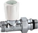
37 3 NPT THERMOSTATIC RADIATOR VALVE BODIES 220 Angled radiator valve body. Order thermo-electric actuators or thermostatic control heads separately for field installation. Chrome plated. Max. working pressure: 150 psi (10 bar). Temperature range: F (5 100 C). 221 Straight radiator valve body. Order thermo-electric actuators or thermostatic control heads separately for field installation. Chrome plated. Max. working pressure: 150 psi (10 bar). Temperature range: F (5 100 C). Code Description Cv Lbs USD A ½" FNPT in, ½" NPT male union out A ¾" FNPT in, ¾" NPT male union out Code Description Cv Lbs USD A ½" FNPT in, ½" NPT male union out A ¾" FNPT in, ¾" NPT male union out Replacement internal valve assembly fits radiator valves. Universal radiator tool for installing ½ and ¾" tail pieces. F36073 ½" and ¾" Radiator tool EUROPEAN TOWEL WARMER RADIATOR VALVES 338 Angled radiator valve body. Convertible from standard manual operation to automatic control with thermostatic control heads. Chrome plated. Fits copper, single and multilayer PEX pipes. Max. working pressure: 150 psi (10 bar). Temperature range: ºF (5 100ºC). 342 Angled isolation and balancing valve. Chrome plated. Fits copper, single and multilayer PEX pipes. Max. working pressure: 150 psi (10 bar). Temperature range: ºF (5 100ºC). Code Radiator Connection Pipe Connection Cv Lbs USD ½" straight ¾" conical Code Radiator Connection Pipe Connection Cv Lbs USD ½" straight ¾" conical Straight radiator valve body. Convertible from standard manual operation to automatic control with thermostatic control heads. Chrome plated. Fits copper, single and multilayer PEX pipes. Max. working pressure: 150 psi (10 bar). Temperature range: ºF (5 100ºC). 343 Straight isolation and balancing valve. Chrome plated. Fits copper, single and multilayer PEX pipes. Max. working pressure: 150 psi (10 bar). Temperature range: ºF (5 100ºC). Code Radiator Connection Pipe Connection Cv Lbs USD ½" straight ¾" conical Code Radiator Connection Pipe Connection Cv Lbs USD ½" straight ¾" conical Intended for use in metric radiators such as European towel warmers and panel radiators. 37
 and angled (pipes exiting the wall). The two-pipe version is equipped with two ball shut-off valves.")


38 3 CONNECTION VALVES FOR PANEL RADIATORS Caleffi panel radiator valves are designed to be connected to the bottom of panel radiators. They come in two versions: for two-pipe and one-pipe systems. Both are available straight (pipes exiting the floor) and angled (pipes exiting the wall). The two-pipe version is equipped with two ball shut-off valves. The one-pipe, in addition to the shut-off valves, is equipped with an adjustable by-pass from 30% to 50% of the flow rate towards the radiator, and a flow check valve device (1) prevents thermo-syphoning upward into radiator from by-passing flow. Code 3010 Valve for panel radiators that have built-in thermostatic valve unit. Two-pipe straight version (floor connections) fits ½" female radiator connections. Max. working pressure: 150 psi (10 bar). Max. working temperature: 212 F (100 C). Radiator Connection Pipe Connection Lbs USD ½" straight ¾" conical Code 3011 Valve for panel radiators that have built-in thermostatic valve unit. Two-pipe valve angled version (wall connections) fits ½" female radiator connections. Max. working pressure: 150 psi (10 bar). Max. working temperature: 212 F (100 C). Radiator Connection Pipe Connection Lbs USD ½" straight ¾" conical Code 3012 Valve for panel radiators that have built-in thermostatic valve unit. One-pipe straight version (floor connections) fits ½" female radiator connections. With adjustable by-pass. Balance knob. Max. working pressure: 150 psi (10 bar). Max. working temperature: 212 F (100 C). Radiator Connection Pipe Connection Lbs USD ½" straight ¾" conical One-Pipe Plumbing Two-Pipe Plumbing Code 3013 Valve for panel radiators that have built-in thermostatic valve unit. One-pipe angled version (wall connections) fits ½" female radiator connections. With adjustable by-pass. Balance knob. Max. working pressure: 150 psi (10 bar). Max. working temperature: 212 F (100 C). Radiator Connection Pipe Connection Lbs USD ½" straight ¾" conical Wall-covering plate. Fits dual panel radiator valves 301. With wall connections. In white ABS. Outlet center distance: mm Plate
39 A 3 CONNECTION FITTINGS 681 Universal PEX fittings 681 series fittings are compatible with any ASTM F876 single layer PEX. Working temperature for ASTM F876 PEX piping: ºF. Chrome plated nut. 682 Universal PEX-AL-PEX fittings 682 series fittings are compatible with any ASTM F1281 multilayer PEX-AL-PEX pipe. Working temperature for ASTM F1281 PEX-AL-PEX piping: ºF with tubing rated 200ºF A 3 /8 " nominal PEX ½" nominal PEX /8 " nominal PEX A ½" PEX-AL-PEX adaptors Compression fitting, fits ½" hard copper. With o-ring seal. Working temperature range: ºF. Chrome plated. For connecting copper to valve 301, 338, 339, 342 and 343 series. A Z Z ½" compression (2-pack) NA Radiator adapter for directly connecting a panel radiator with PEX, PEX-AL-PEX, sweat, NPT or compression fittings. Package of 2 each, priced per package. Sweat connection fitting fits ½" copper. Working temperature range: ºF. Chrome plated nut. For connecting copper to valve 301, 338, 339, 342 and 343 series. NA10262 ½" sweat ½" M straight x ¾" M conical (2 ea.) Wrench for tightening PEX fitting to TRV. NA103 NPT connection fitting. Working temperature range: ºF. Chrome plated nut. For connecting copper to valve 301, 338, 339, 342 and 343 series mm x 30 mm NA10313 ½" NPT male
40 40 3
41 3 ZONE VALVES AND ZONE CONTROLS This diagram is for illustration purposes only 4 PRODUCTS INCLUDED IN SECTION Thermo-electric zone valves Thermo-electric actuators Motorized zone valves Pump zone controls Valve zone controls Motorized ball zone valves, high-flow, high-close off 41
. 31.")

: NEMA 3 (IP54) Power supply: 24 V AC/DC. Initial current draw: 250 ma.")
42 4 THERMO-ELECTRIC ZONE VALVES 6767 TwisTop+ High Performance Complete with actuator. Spring return. Normally closed. Pressure balanced body. Brass valve body and trim. Max. body pressure: 150 psi. Max. Temperature: 200 F. Power supply: 24 V AC/DC. Initial current draw: 250 ma. Power consumption: holding: 3 W inrush: 6 VA Rating of micro-switch contacts: 5 A (24 V). 31.5" wire lead connection TwisTop Zone valve Two-way thermo-electric zone valve. Complete with TwisTop (code ) actuator. Spring return. Normally closed. Brass valve body and trim. Max. body pressure: 150 psi. Max. Temperature: 200 F. Power supply: 24 V AC/DC. Initial current draw: 250 ma. Power consumption: holding: 3 W inrush: 6 VA Rating of micro-switch contacts: 5 A (24 V). 31.5" wire lead connection. Code Description Cv ΔP Lbs USD A ¾" press union psi A ¾" sweat union psi A ¾" PEX expansion union psi A 1" press union psi A 1" sweat union psi A 1" PEX expansion union psi Thermo-electric actuator fits on 676 two-way zone valve bodies. Low current draw. Protection class (installed in all positions): NEMA 3 (IP54) Power supply: 24 V AC/DC. Initial current draw: 250 ma. Power consumption: holding: 3 W inrush: 6 VA Rating of micro-switch contacts: 5 A (24 V). 31.5" wire lead connection. Code Description Cv ΔP Lbs USD A ¾" press union 4 20 psi A ¾" sweat union 4 20 psi A ¾" PEX expansion union 4 20 psi A 1" press union 4 20 psi A 1" sweat union 4 20 psi A 1" PEX expansion union 4 20 psi TwisTop TwisTop thermo-electric actuator fits on 676 two-way valve. Twist the top to manually open and close micro-switch. Power supply: 24 V AC/DC. Initial current draw: 250 ma. Power consumption: holding: 3 W inrush: 6 VA Rating of micro-switch contacts: 5 A (24 V). 31.5" wire lead connection. US Patent 7,617,989 B V AC/DC V AC/DC with micro-switch , 6765 Two-way zone valve body. For field installation of thermo-electric actuators 6563 series or 6564 series. Brass body and trim. Max. body pressure: 150 psi. Max. temperature: 200 F. See fitting selection table in Section 8. Select fittings with 1" nut V AC/DC V AC/DC with micro-switch Up to 12 actuators per 40 VA transformer. 40 VA Code Description Cv Lbs USD A body only, close-off 20 psid A body only, close-off 35 psid
.")

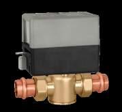
43 4 MOTORIZED ZONE VALVES Z4 2-way Two-way zone valve. Spring return. Normally closed actuator: Z Auxiliary micro-switch. Max. body pressure: 300 psi. Temperature range: 32º 240 F. Suitable fluids: water, 50% max. glycol, 15 psi max. steam. Power supply: 24 V AC. Power consumption: 5 W, 7 VA. Rating of auxiliary micro-switch contacts: 0.0 A min, 0.4 A max 24 V (24 V only). 18" wire lead connection. UL873, culus Listed & CE. UL 1995 sec. 18 air plenums and ducts. US Patent 7,048,251. Z5 2-way Two-way zone valve. Spring return. Normally closed actuator: Z Auxiliary micro-switch. Max. body pressure: 300 psi. Temperature range: 32º 240 F. Suitable fluids: water, 50% max. glycol, 15 psi max. steam. Power supply: 24 V AC. Power consumption: 5 W, 7 VA. Rating of auxiliary micro-switch contacts: 0.0 A min, 0.4 A max 24 V (24 V only). Screw terminal connection. UL873, culus Listed & CE. UL 1995 sec. 18 air plenums and ducts. US Patent 7,048,251. Code Description Cv P Lbs USD Z40 Inverted flare psi Z40F ¾" Inv flare* psi Z42 ½" SAE flare psi Z44 ½" sweat psi Z45 ¾" sweat psi Z46 1" sweat psi Z47 1¼" sweat psi * Two ¾" sweat fittings (NA10006) included. 2-way Press Two-way zone valve. Spring return. Normally closed actuator. Auxiliary micro-switch. Max. body pressure: 300 psi. Overall length: 5-5 /8" Temperature range: F. Suitable fluids: water, 50% max. glycol, 15 psi max. steam. Power supply: 24 V AC. Power consumption: 5 W, 7 VA. Rating of auxiliary micro-switch contacts: 0.0 A min, 0.4 A max 24 V (24 V only). UL873, culus Listed & CE. UL 1995 sec. 18 air plenums and ducts. US Patent 7,048,251. Code Description Cv P Lbs USD Z50 Inverted flare psi Z50F ¾" Inv flare* psi Z54 ½" sweat psi Z55 ¾" sweat psi Z56 1" sweat psi Z57 1¼" sweat psi * Two ¾" sweat fittings (NA10006) included. Inverted flare sweat adaptors fits Z40, Z50 and inverted flare valve body. NA10005 ½" sweat NA10006 ¾" sweat NA " sweat NA61241 Retrofit extension kit Press Installation Cut tube end square and to desired length. Clean any debris from inside of tube. Deburr or ream inside and outside of tube. Code Description Cv P Lbs USD Z44P ½" press* psi Z54P ½" press** psi Z45P ¾" press* psi Z55P ¾" press** psi Z45PL ¾" press* psi Z55PL ¾" press** psi Z46P 1" press* psi Z56P 1" press** psi *18" wire lead connection. **Screw terminal connection. PL (1) extra long press fitting for retrofit Includes press fittings. Make sure surface is smooth and without burrs or sharp edges. Insert the tube into the fitting, make sure the tube is fully inserted and mark with a marker to indicate proper insertion depth ( 7 /8 ). Check that the proper clamping jaws are installed and open jaw arms to set. Place jaw around valve end and double check proper insertion depth, press fitting. 43

. 120-277 VAC: 0.25 A min, 5.0 A max (230 V).")

44 4 MOTORIZED ZONE VALVES Z1 Normally Closed Z1 NC actuator fits on Z2 and Z3 series valve bodies with the push of a button. Two position spring return normally closed. 7/8" knockout for 1/2" conduit connector. Power: 24, 120, 208, 230 & 277 VAC. Power consumption: 5 W, 7 VA. Conduct connector size: ½". Rating of auxiliary switch contacts: 24 VAC: 0.0 A min, 0.4 A max (24 V) and Z VAC: 0.25 A min, 5.0 A max (230 V). UL873, culus Listed & CE. UL 1995 sec.18 air plenums and ducts. US Patent 7,048,251. Z1 Normally Open Z1 NO actuator fits on Z2 series valve bodies with the push of a button. Two position spring return normally opened. 7/8" knockout for 1/2" conduit connector. Power: 24, 120, 208, 230 & 277 VAC. Power consumption: 5 W, 7 VA. Conduct connector size: ½". Rating of auxiliary switch contacts: 24 VAC: 0.0 A min, 0.4 A max (24 V) VAC: 0.25 A min, 5.0 A max (230 V). UL873, culus Listed & CE. UL 1995 sec. 18 air plenums and ducts. US Patent 7,048,251. Z V, micro-switch, 18" wires Z V, high current switch, 18" wires Z V, micro-switch, 6" wires Z V, micro-switch, 6" wires Z V, micro-switch, 6" wires Z V, micro-switch, 6" wires Z V, micro-switch, terminal blocks Z V, terminal blocks Z V, 18" wires Z V, 6" wires Z V, 6" wires Z V, 6" wires Z V, 6" wires Z V, micro-switch, 18" wires Z V, micro-switch, 6" wires Z V, micro-switch, 6" wires Z V, 18" wires Z V, 6" wires Z V, 6" wires Z V, 6" wires Z V, 6" wires Construction DURABLE SYNCHRONOUS MOTOR Function The Z-one valve is a truly universal zone valve that can be used in a wide range of commercial and residential applications; from fan coils to baseboard, radiant to high rise, the Z-one is the professional s valve of choice. The Z-one can be used in both chilled or hot water and low pressure steam applications. With Delta P close off pressures of up to 75 PSI, the Z-one outperforms all other zone valves. The Z-one is available in sizes from ½ to 1¼ sweat or NPT connections on valve body, with removable actuator available in 24 to 277 voltages. Some models of Z-one actuators contain an auxiliary micro-switch to operate other devices. The 24 V actuators use a sealed reed switch, which has been produced specifically for use with relays, boiler contacts (TT) and DDC systems. It requires no minimum current load. The 120 V V actuators for applications requiring greater than 400 ma, use a conventional micro-switch with silver contacts. The auxiliary switch is activated when the valve is 60% open or when the actuator is manually opened. Manual opening (Normally closed actuator only) The valve can be opened manually by moving the lever for opening it. When the power is restored the manual control is automatically overridden. The auxiliary switch in 24 V actuators is tripped when the unit is put into manual open position. This helps during start up to check if the wiring is correct without firing the valve electrically with the thermostat. MANUAL OPENING LEVER AND POSITION INDICATOR EXTRA THICK SECTOR GEAR PUSH BUTTON FOR EASY ASSEMBLY AND REMOVAL FORGED BRASS BODY, 300 PSI RATED STAINLESS STEEL STEM REMOVABLE CAP SERVICEABLE IN-PIPE Easy push button CORROSION-RESISTANT ACTUATOR MATERIALS CLUTCH-PROTECTED DRIVE TRAIN SEALED AUXILIARY SWITCH (OPTIONAL) TRUE MECHANICAL SPRING RETURN LARGE VALVE CAVITY FOR QUIET FLOW, PREVENTS WATER HAMMER HIGH TEMPERATURE EPDM O-RINGS AND PADDLE (240ºF) A simple push of the button makes it easy to remove it from the body of the valve for maintenance or replacement operations. Warning: the actuator can only be used with valve bodies Z2-Z3 series. Operation The actuator is fitted with a special mechanism for gradual movement of the valve paddle which provides smooth and quiet constant operation. Poweron full stroke run time is 60 seconds with 6 second power-off return time eliminating the effects of water hammer. 44


45 4 MOTORIZED ZONE VALVES Z2 2-way Two-way on/off two position valve. Straight through flow pattern. Brass body. Stainless steel stem. EPDM rubber seals and paddle. Max. working pressure: 300 psi. Max temperature: 240 F. Z3 3-way Three-way on/off two position valve. Diverting flow pattern. Brass body. Stainless steel stem. EPDM rubber seals and paddle. Max. working pressure: 300 psi. Max temperature: 240 F. Code Description Cv P Lbs USD Z Inverted flare 1 75 psi Z Inverted flare psi Z Inverted flare psi Z ½" SAE Flare psi Z ½" FNPT 1 75 psi Z ½" FNPT LL 1 75 psi Z ½" FNPT psi Z ½" FNPT psi Z ½" sweat 1 75 psi Z ½" sweat psi Z ½" sweat LL psi Z ¾" FNPT psi Z ¾" FNPT psi Z ¾" FNPT 5 25 psi Z ¾" FNPT psi Z ¾" sweat psi Z207533* ¾" sweat LL psi Z ¾" sweat 5 25 psi Z ¾" sweat psi Z207537* ¾" sweat LL psi Z " FNPT psi Z " sweat 5 25 psi Z " sweat psi Z ¼" sweat psi LL Low-lead brass body. Two-way and three-way zone valve body repair kit. Includes valve stem paddle with O-rings, C clip and one bottom cap O-ring. Code Description Cv P Lbs USD Z ½" SAE Flare psi Z ½" FNPT 1 75 psi Z ½" FNPT psi Z ½" FNPT psi Z ½" sweat 1 75 psi Z ½" sweat psi Z307433* ½" sweat LL psi Z ¾" FNPT psi Z ¾" FNPT psi Z ¾" FNPT 5 25 psi Z ¾" FNPT psi Z ¾" sweat psi Z ¾" sweat psi Z ¾" sweat 5 25 psi Z307537* ¾" sweat LL psi Z " FNPT psi Z " sweat 5 25 psi Z " sweat psi Z ¼" sweat psi *LL Low-lead brass body. 2-way male union valve body. Select fittings in Section 8 Table. Code Description Cv P Lbs USD Z " male union body psi Z " male union body psi way male union valve body. Select fittings in Section 8 Table. F69293 Fits all ½" & ¾" sweat Z2, Z3 valves F69294 Fits all ¾" NPT and all 1" Z2, Z3 valves Code Description Cv P Lbs USD Z " male union body psi


 max combined Electrical switch rating pump output: 120 VAC, 5A each Dry contact rating: AUX, XX, ZONE1 E/S: 120 VAC max, 2A each Replaceable fuses: Type 2AG, 5A slow blow ZSR101 Single")
46 4 PUMP ZONE CONTROLS ZSR The ZSR series is multi-zone pump and boiler operating control for multiple zone hydronic heating systems. The ZSR series interfaces with low voltage thermostats, or any other low voltage controllers having a switching action. The ZSR series controls up to 3, 4, 5 or 6 heating circulator pumps, depending on model selected, a primary pump and has LED indicators to provide functional status and easy system troubleshooting. In addition, a primary pump system circulator is switched on whenever any zone calls for heat Certified to CSA C22-2 No.24 Conforms to UL Standard 873 Power supply: 120 VAC, 50/60 Hz Transformer voltage: 24 VAC Maximum transformer load: 12 VA (ZSR101/103/104), 20 VA (ZSR106) Electrical switch rating: 10A (ZSR101), 20A (ZSR103/4/6) max combined Electrical switch rating pump output: 120 VAC, 5A each Dry contact rating: AUX, XX, ZONE1 E/S: 120 VAC max, 2A each Replaceable fuses: Type 2AG, 5A slow blow ZSR101 Single zone relay ZSR103 3 zone pump control ZSR104 4 zone pump control ZSR106 6 zone pump control VALVE ZONE CONTROLS ZVR The ZVR series is a multi-zone valve relay and boiler operating control for multiple zone hydronic heating systems. The ZVR series interfaces with low voltage thermostats, or any other low voltage controllers having a switching action. The ZVR series controls up to 3, 4, 5 or 6 zones, depending on model selected. In addition, a system circulator pump and secondary pump is turned on whenever any zone calls for heat. LED indicators provide functional status and easy system troubleshooting. The ZVR series is a perfect match with Caleffi s Z-one motorized zone valves Certified to CSA C22-2 No.24 Conforms to UL Standard 873 Power supply: 120 VAC, 50/60 Hz Transformer voltage: 24 VAC Maximum transformer load: 40 VA (ZVR103/4), 80 VA (ZVR106) Electrical switch rating: 20A Max Combined Electrical switch rating pumps: 120 VAC, 5A each Dry contact rating: AUX, XX, ZONE1 E/S:120 VAC, 2A each Resettable Fuse: automatic High Capacity 40 VA Transformer standard for 3 and 4 zone modelsexpandable to 80 VA, and 80 VA for the 6 zone model Z-ONE RELAY FUSES NA10342 Spare fuse (package of 5) ZVR103 3 zone valve control ZVR104 4 zone valve control ZVR106 6 zone valve control NA10343 Expansion transformer
. 3-wire control. 36\" wire lead connection. 13 Cv Code Description Cv Lbs USD 644250A ¾\" NPT male union 13 2.")

47 4 MOTORIZED BALL ZONE VALVES HIGH-FLOW, HIGH CLOSE-OFF way Straight Two-way motorized ball zone valve. Straight. Max. P close-off pressure: 150 psi. Temperature range: 20º 230 F. Power supply: 24 VAC. Power consumption: 4 VA. Rating of micro-switch contacts: 5 A (24 V). 3-wire control. 36" wire lead connection. 13 Cv Code Description Cv Lbs USD A ¾" NPT male union A ¾" press union A ¾" sweat union A 1" NPT male union A 1" press union A 1" sweat union NA644200* body, with no fittings *See fitting selection table in Section BY 3-way By-pass Three-way motorized ball zone valve. By-pass. Max. P close-off pressure: 150 psi. Temperature range: 20º 230 F. Power supply: 24 VAC. Power consumption: 4 VA. Rating of micro-switch contacts: 5 A (24 V). 3-wire control. 2.1 Cv in by-pass mode. 36" wire lead connection. Code Description Cv Lbs USD A 3BY ¾" NPT male union A 3BY ¾" press union A 3BY ¾" sweat union A 3BY 1" NPT male union A 3BY 1" press union A 3BY 1" sweat union NA BY* body, no fittings *See fitting selection table in Section V 3-wire control Actuator fits 6442 and 6443 series. Power supply: 24 VAC. Power consumption: 4 VA. Rating of micro-switch contacts: 5 A (24 V). Operating time: 40 s (90 rotation). Length of supply cable: 36" VAC way Diverting Three-way motorized ball zone valve. Diverting. Max. P close-off pressure: 150 psi. Temperature range: 20º 230 F. Power supply: 24 VAC. Power consumption: 4 VA. Rating of micro-switch contacts: 5 A (24 V). 3-wire control. 36" wire lead connection. Code Description Cv Lbs USD A ¾" NPT male union A ¾" press union A ¾" sweat union A 1" NPT male union A 1" press union A 1" sweat union NA644300* body, no fittings *See fitting selection table in Section 8. 47
48 48 4
49 VENT DISTRIBUTION MANIFOLDS AND TEMPERATURE MIXING STATIONS This diagram is for illustration purposes only ºF PRODUCTS INCLUDED IN SECTION Pump and valve temperature mixing units Thermostatic manifold mixing stations Manifold mixing stations Brass distribution manifolds Distribution manifolds Boxes for distribution manifolds Fittings for distribution manifolds and mixing stations Brass distribution manifold accessories Accessories


50 12135 PUMP & VALVE TEMPERATURE MIXING UNITS 165 HydroMixer Injection pump mixing unit with insulation. Grundfos UPS three speed pump. Grundfos Alpha 25-55U pump. Temperature gauges. Shut-off ball valves. Compatible with 5599 Hydrolink series Male union connections (select top and bottom fitting sets on page 35). Max working pressure: 145 psi. Max. working temperature: 212 F. Power supply: 115 V 50/60 Hz A Dual line with pump on right 21 1, A Dual line with pump on left 21 1, A Dual line with Alpha pump on right 21 1, A Dual line with Alpha pump on left 21 1, HydroLink with 165, 166, 167 HydroMixers Wall bracket fits 165, 166 and 167 series Wall bracket Outlet fittings required when using a HydroMixer with a Hydrolink. 50


. Max working pressure: 145 psi.")


 1¼\" union nuts, (2) tail pieces and (2) washers. Will not fit bottom inlet thread. NA16069 1\" sweat union outlet fittings 1.0 90.")
 1½\" union nuts, (2) tail pieces and (2) washers. Will not fit top outlet thread. NA16169 1\" sweat union inlet fittings 1.0 91.")
51 12135 PUMP & VALVE TEMPERATURE MIXING UNITS 166 HydroMixer Thermostatic adjustable temperature mixing unit with insulation. Grundfos UPS three speed pump. Grundfos Alpha 25-55U pump. Temperature gauges. Shut-off ball valves. Compatible with 5599 Hydrolink series Male union connections (select top and bottom fitting sets below). Max working pressure: 145 psi. Adjustable range: F. Power supply: 115 V 50/60 Hz. 167 HydroMixer Motorized temperature mixing unit with insulation. Three-point floating 24 VAC actuator for use with separately-sourced outdoor reset controller. Grundfos UPS three speed pump. Grundfos Alpha 25-55U pump. Temperature gauges. Shut-off ball valves. Compatible with 5599 Hydrolink series Male union connections (select top and bottom fitting sets below). Max working pressure: 145 psi. Primary inlet temperature range: F Power supply: 115 V 50/60 Hz. Valve actuator: 24 V AC A Dual line with pump on right 22 1, A Dual line with pump on left 22 1, A Dual line with Alpha pump on right 22 2, A Dual line with Alpha pump on left 22 2, A Dual line with pump on right 23 2, A Dual line with pump on left 23 2, A Dual line with Alpha pump on right 23 2, A Dual line with Alpha pump on left 23 2, Optional differential pressure by-pass valve fits 165, 166 and 167 series. Top outlet fitting set fits 165, 166, 167 series. Includes (2) 1¼" union nuts, (2) tail pieces and (2) washers. Will not fit bottom inlet thread. NA " sweat union outlet fittings Differential pressure by-pass valve Bottom Inlet fitting set fit 165, 166, 167 series. Includes (2) 1½" union nuts, (2) tail pieces and (2) washers. Will not fit top outlet thread. NA " sweat union inlet fittings Top outlet fitting set fits 165, 166, 167 series. Includes (2) 1¼" union nuts, (2) tail pieces and (2) washers. Will not fit bottom inlet thread. NA " NPT male union outlet fittings Bottom Inlet fitting set fit 165, 166, 167 series. Includes (2) 1½" union nuts, (2) tail pieces and (2) washers. Will not fit top outlet thread. NA " NPT female union inlet fittings

52 12135 THERMOSTATIC MANIFOLD MIXING STATIONS 172 Manifold mixing station three speed pump Pre-assembled thermostatic manifold mixing station consisting of a supply distribution manifold complete with built-in sight flow gauges and adjustable balancing valves. Return manifold with built-in shutoff valves is suitable for thermo-electric actuators. Complete with built-in sensor to keep flow temperature at constant set value. Includes Grundfos UPS three-speed pump. ¾" F NPT supply/return ball valves. Control temperature range: F Primary inlet max. temperature: 195 F Outlet center distance: 2 in. Models with "...IN" suffix are built inverted (tubing connections going upward). 172 Manifold mixing station high efficiency pump Pre-assembled thermostatic manifold mixing station consisting of a supply distribution manifold complete with built-in sight flow gauges and adjustable balancing valves. Return manifold with built-in shutoff valves is suitable for thermo-electric actuators. Complete with built-in sensor to keep flow temperature at constant set value. Includes Grundfos Alpha 25-55U pump. ¾" F NPT supply/return ball valves. Control temperature range: F Primary inlet max. temperature: 195 F Outlet center distance: 2 in. Models with "...IN" suffix are built inverted (tubing connections going upward). Code Description UPS Pump No. Outlets Lbs USD 1725C1A ¾" ¾" M 20 1, C1A IN ¾" ¾" M 20 1, D1A ¾" ¾" M 21 1, D1A IN ¾" ¾" M 21 1, E1A ¾" ¾" M 23 2, E1A IN ¾" ¾" M 23 2, F1A ¾" ¾" M 25 2, F1A IN ¾" ¾" M 25 2, G1A ¾" ¾" M 27 2, G1A IN ¾" ¾" M 27 2, H1A ¾" ¾" M 28 2, H1A IN ¾" ¾" M 28 2, I1A ¾" ¾" M 29 2, I1A IN ¾" ¾" M 29 2, L1A ¾" ¾" M 31 2, L1A IN ¾" ¾" M 31 2, M1A ¾" ¾" M 33 2, M1A IN ¾" ¾" M 33 2, N1A ¾" ¾" M 34 2, N1A IN ¾" ¾" M 34 2, O1A ¾" ¾" M 36 3, O1A IN ¾" ¾" M 36 3, Code Description Alpha Pump No. Outlets Lbs USD 1725C1AHE ¾" 25-55U 3 ¾" M 20 2, C1AHE IN ¾" 25-55U 3 ¾" M 20 2, D1AHE ¾" 25-55U 4 ¾" M 21 2, D1AHE IN ¾" 25-55U 4 ¾" M 21 2, E1AHE ¾" 25-55U 5 ¾" M 23 2, E1AHE IN ¾" 25-55U 5 ¾" M 23 2, F1AHE ¾" 25-55U 6 ¾" M 25 2, F1AHE IN ¾" 25-55U 6 ¾" M 25 2, G1AHE ¾" 25-55U 7 ¾" M 27 2, G1AHE IN ¾" 25-55U 7 ¾" M 27 2, H1AHE ¾" 25-55U 8 ¾" M 28 2, H1AHE IN ¾" 25-55U 8 ¾" M 28 2, I1AHE ¾" 25-55U 9 ¾" M 29 2, I1AHE IN ¾" 25-55U 9 ¾" M 29 2, L1AHE ¾" 25-55U 10 ¾" M 31 3, L1AHE IN ¾" 25-55U 10 ¾" M 31 3, M1AHE ¾" 25-55U 11 ¾" M 33 3, M1AHE IN ¾" 25-55U 11 ¾" M 33 3, N1AHE ¾" 25-55U 12 ¾" M 34 3, N1AHE IN ¾" 25-55U 12 ¾" M 34 3, O1AHE ¾" 25-55U 13 ¾" M 36 3, O1AHE IN ¾" 25-55U 13 ¾" M 36 3,


53 CALEFFI L/MIN CAMERA CAMERA CALEFFI L/MIN SOGGIORNO SOGGIORNO L/MIN WC WC CALEFFI CALEFFI THERMOSTATIC MANIFOLD MIXING STATIONS Characteristic components / hydraulic diagram Item Description Symbol 1 Circulation pump UPS pictured 2 Top elbow with supply temperature and pressure gauge 3 Purge valve 4 Supply temperature and pressure gauge 5 Return temperature gauge SYSTEM FLOW SYSTEM RETURN Supply manifold equipped with flow meters and balancing valves. Return manifold equipped with shut-off valves T 5 SYSTEM FLOW SYSTEM RETURN 6 Primary circuit shut-off valves Primary circuit hydraulic separator with check valve 8 Thermostatic three-way mixing valve with built-in sensor T BOILER FLOW BOILER RETURN End fittings with automatic air vent with hygroscopic cap and drain cock. 6 BOILER FLOW 6 BOILER RETURN Function The 172 series manifold mixing station is designed for use in manifold-based hydronic distribution systems. The manifold mixing station incorporates a thermostatic actuator with built-in sensor which keeps the flow temperature at a constant set value for use in low temperature systems such as floor radiant panels. A removable primary circuit hydraulic separator with check valve is also supplied. The hydraulic separator is essential when there is a primary circuit circulation pump and when radiator circuits or fan coils are controlled by thermostatic or thermo-electric valves. When connecting to a Caleffi HYDROLINK TM or hydraulic separator without a primary pump, the hydraulic separator can be removed and the manifold mixing station can be connected directly. The 172 station, like the TWISTFLOW TM Series 668S1 distribution manifolds, can be configured with 3 to 13 circuit outlets offering similar benefits with built-in sight flow meters/adjustable balancing valves and optional TWISTOP TM thermo-electric zone actuators. MANIFOLD MIXING STATIONS Thermostatic mixing station kit For field assembly to a Caleffi radiant manifold assembly. Grundfos UPS three-speed pump or Alpha 25-55U. 1" NPT male adapters included to connect to manifold. ¾" NPT female riser connections. Includes built-in hydraulic separator. NA17256HE Thermostatic mixing, Alpha 25-55U 4.1 1, NA17256 Thermostatic mixing, UPS 15-58U 4.1 1, NA16002 Alpha 25-55U replacement pump NA10038 UPS 15-58U replacement pump F19153 Replacement mixing valve

54 12135 BRASS DISTRIBUTION MANIFOLDS 668S1 TwistFlow Assembly Pre-assembled radiant manifold consisting of return distribution manifold complete with built-in shut-off valves suitable for thermo-electric actuator and supply distribution manifold complete with built-in sight flow meters and balancing valves with 2" gauges F scale. 1" or 1¼" NPT inlet ball valves. Temperature gauges. Max. working temperature: 180 F. Max: peak temperature: 200 F. Loop Cv: 1.23 (combined supply & return ports). Flow meter scale: ¼ 2 gpm. Outlet center distance: 2 in. Models with "...IN" suffix are built inverted (tubing connections going upward). Code Description No. Outlets Lbs USD 6686C5S1A 1" 3 ¾" M C5S1A IN 1" 3 ¾" M D5S1A 1" 4 ¾" M D5S1A IN 1" 4 ¾" M E5S1A 1" 5 ¾" M 19 1, E5S1A IN 1" 5 ¾" M 19 1, F5S1A 1" 6 ¾" M 21 1, F5S1A IN 1" 6 ¾" M 21 1, G5S1A 1" 7 ¾" M 23 1, G5S1A IN 1" 7 ¾" M 23 1, H5S1A 1" 8 ¾" M 24 1, H5S1A IN 1" 8 ¾" M 24 1, I5S1A 1" 9 ¾" M 26 1, I5S1A IN 1" 9 ¾" M 26 1, L5S1A 1" 10 ¾" M 28 1, L5S1A IN 1" 10 ¾" M 28 1, M5S1A 1" 11 ¾" M 29 1, M5S1A IN 1" 11 ¾" M 29 1, N5S1A 1" 12 ¾" M 31 1, N5S1A IN 1" 12 ¾" M 31 1, O5S1A 1" 13 ¾" M 33 2, O5S1A IN 1" 13 ¾" M 33 2, Code Description No. Outlets Lbs USD 6687C5S1A 1¼" 3 ¾" M C5S1A IN 1¼" 3 ¾" M D5S1A 1¼" 4 ¾" M 18 1, D5S1A IN 1¼" 4 ¾" M 18 1, E5S1A 1¼" 5 ¾" M 19 1, E5S1A IN 1¼" 5 ¾" M 19 1, F5S1A 1¼" 6 ¾" M 21 1, F5S1A IN 1¼" 6 ¾" M 21 1, G5S1A 1¼" 7 ¾" M 23 1, G5S1A IN 1¼" 7 ¾" M 23 1, H5S1A 1¼" 8 ¾" M 24 1, H5S1A IN 1¼" 8 ¾" M 24 1, I5S1A 1¼" 9 ¾" M 26 1, I5S1A IN 1¼" 9 ¾" M 26 1, L5S1A 1¼" 10 ¾" M 28 1, L5S1A IN 1¼" 10 ¾" M 28 1, M5S1A 1¼" 11 ¾" M 29 1, M5S1A IN 1¼" 11 ¾" M 29 1, N5S1A 1¼" 12 ¾" M 31 2, N5S1A IN 1¼" 12 ¾" M 31 2, O5S1A 1¼" 13 ¾" M 33 2, O5S1A IN 1¼" 13 ¾" M 33 2, Manifolds and accessories 1. Thermo-electric actuator 6564 series. 2. Thermo-electric actuator with manual open handle, 6563 series. 3. Self-adjusting Universal PEX fitting, 680, 682 series. 4. Inspection wall box, 659 series. 5. Differential by-pass kit, code

55 CALEFFI CAMERA CALEFFI CAMERA HOBBY HOBBY SOGGIORNO SOGGIORNO WC WC DISTRIBUTION MANIFOLDS 663 Pre-assembled distribution assembly Pre-assembled distribution assembly consisting of return distribution manifold complete with built-in shut-off valves suitable for thermo-electric actuator and supply distribution manifold complete with manuallyadjustable balancing valves. 1" or 1¼" NPT inlet ball valves. Loop Cv: 2.3 (combined supply & return ports). Max: temperature: 210 F. Outlet center distance: 2 in. Models with "...IN" suffix are built inverted (tubing connections going upward). Code Description No. Outlets Lbs USD 6636C5A 1" 3 ¾" M C5A IN 1" 3 ¾" M D5A 1" 4 ¾" M D5A IN 1" 4 ¾" M E5A 1" 5 ¾" M E5A IN 1" 5 ¾" M F5A 1" 6 ¾" M 21 1, F5A IN 1" 6 ¾" M 21 1, G5A 1" 7 ¾" M 23 1, G5A IN 1" 7 ¾" M 23 1, H5A 1" 8 ¾" M 24 1, H5A IN 1" 8 ¾" M 24 1, I5A 1" 9 ¾" M 26 1, I5A IN 1" 9 ¾" M 26 1, L5A 1" 10 ¾" M 28 1, L5A IN 1" 10 ¾" M 28 1, M5A 1" 11 ¾" M 29 1, M5A IN 1" 11 ¾" M 29 1, N5A 1" 12 ¾" M 31 1, N5A IN 1" 12 ¾" M 31 1, O5A 1" 13 ¾" M 33 1, O5A IN 1" 13 ¾" M 33 1, P5A 1" 14 ¾" M 35 2, P5A IN 1" 14 ¾" M 35 2, Code Description No. Outlets Lbs USD 6637C5A 1¼" 3 ¾" M C5A IN 1¼" 3 ¾" M D5A 1¼" 4 ¾" M D5A IN 1¼" 4 ¾" M E5A 1¼" 5 ¾" M E5A IN 1¼" 5 ¾" M F5A 1¼" 6 ¾" M 21 1, F5A IN 1¼" 6 ¾" M 21 1, G5A 1¼" 7 ¾" M 23 1, G5A IN 1¼" 7 ¾" M 23 1, H5A 1¼" 8 ¾" M 24 1, H5A IN 1¼" 8 ¾" M 24 1, I5A 1¼" 9 ¾" M 26 1, I5A IN 1¼" 9 ¾" M 26 1, L5A 1¼" 10 ¾" M 28 1, L5A IN 1¼" 10 ¾" M 28 1, M5A 1¼" 11 ¾" M 29 1, M5A IN 1¼" 11 ¾" M 29 1, N5A 1¼" 12 ¾" M 31 1, N5A IN 1¼" 12 ¾" M 31 1, O5A 1¼" 13 ¾" M 33 1, O5A IN 1¼" 13 ¾" M 33 1, P5A 1¼" 14 ¾" M 35 2, P5A IN 1¼" 14 ¾" M 35 2, Construction CALEFFI 1. Supply manifold. 2. Return manifold complete with shut-off valves that can be used with thermo-electric actuators. 3. Pair of shut-off ball valves (complete with port for optional temperature gauge only for 1 1/4 version). 4. End fittings consisting of a 3-way end fitting, automatic air vent valve and drain cock. 5. Pair of mounting brackets for use with series 659 boxes or direct wall installation. 6. Thermo-electric actuator, series 6564 or Flow meter, code NA669. CALEFFI 55


56 12135 BOXES FOR DISTRIBUTION MANIFOLDS 659 Manifold cabinet Housing wall box fits 663 and 668S1 series manifolds. Adjustable depth: 4 3 /8" 5½". Powder coated painted 18 gauge sheet metal. With push-fit clamp. Code Description H Max Outlets Lbs USD " width 20" " width 20" " width 20" " width 20" " width" 20" Rough opening dimensions 56
57 12135 FITTINGS FOR DISTRIBUTION MANIFOLDS AND MIXING STATIONS (680504A shown) 680 Universal PEX fittings 680 series fittings are compatible with any ASTM F876 single layer PEX. Working temperature range for ASTM F876 PEX piping: F. NA102 Sweat connection fitting fits ½" copper. Working temperature range: ºF. Chrome plated nut. Does not work with 668S1 and 172 series. NA10262 ½" sweat Code Description Compression ring Lbs USD /16" nominal PEX Blue A 3 /8" nominal PEX Black A ½" nominal PEX Blue A 5 /8" nominal PEX Black A ¾" nominal PEX Brass (682530A shown) 682 Universal PEX-AL-PEX fittings 682 series fittings are compatible with any ASTM F1281 multilayer PEX-AL-PEX pipe. Working temperature range for ASTM F1281 PEX-AL-PEX piping: F with tubing rated 200 F. NA103 NPT connection fitting. Working temperature range: ºF. Chrome plated nut. Does not work with 668S1 and 172 series. NA10313 ½" NPT male Cap to plug unused manifold outlets on 592, 663 and 668S1 series A 3 /8" nominal PEX-AL-PEX A ½" nominal PEX-AL-PEX A 5 /8" nominal PEX-AL-PEX A ¾" nominal PEX-AL-PEX Construction details There is a large variety of PEX and PEX-AL-PEX pipes available with a wide range of permissible tolerances. This fitting is designed to adapt to several pipe diameter tolerances. This innovative solution for mechanical fittings has been constructed so that the same fitting can be used for pipes with different external diameter tolerances and differences on internal diameters tolerances while maintaining the nominal dimensions. Resistance to pull out This fitting offers a high degree of resistance to pull out of pipe. Its special clamping system makes it suitable for every application and ensures a leak tight fit. Low pressure losses The internal profile of the adapter (1) is shaped to obtain a Venturi effect when the fluid 1 passes through, reducing pressure losses by 20%, compared to a similar diameter. Insulation ring 2 The fitting is equipped with a rubber insulation element (2) to prevent contact between the aluminium in PEX-AL-PEX pipe and the brass 3 fitting, thus preventing galvanic corrosion generated by the two different metals. Dual O-ring seal 4 The adapter is equipped with two O-ring seals (3) and (4) in EPDM to prevent leaks even when operating at high pressure ¾" straight thread Double nipple for coupling PEX fittings ¾" x ¾" thread Wrench for tightening PEX fitting to manifolds mm x 30 mm

. 31.5\" wire lead connection. 668000 ½\" x ½\" 0.5 131.00 CALEFFI CALEFFI CALEFFI CALEFFI 656404 24 V AC/DC 0.4 114.00 656414 24 V AC/DC with micro-switch 0.")
. 31.5\" wire lead connection. US Patent 7,617,989 B2. The by-bass valve contains a check valve connected to a contact spring.")

58 F F CALEFFI L/MIN CAMERA CALEFF CAMERA L/MIN HOBBY HOBBY L/MIN BATH BATH L/MIN BEDROOM BEDROOM L/MIN WC WC BRASS DISTRIBUTION MANIFOLD ACCESSORIES 668 Off-center by-pass assembly with fixed crack setting of 3.6 psi differential pressure. Max working pressure: 150 psi. Working temperature range: F Low current draw thermo-electric actuator. Hermetically sealed for upside down installation.. Pop-up feature Power supply: 24 V AC/DC. Initial current draw: 250 ma. Power consumption: 3 W. Rating of micro-switch contacts: 5 A (24 V). 31.5" wire lead connection ½" x ½" CALEFFI CALEFFI CALEFFI CALEFFI V AC/DC V AC/DC with micro-switch TwisTop TwisTop thermo-electric actuator. Twist the top to manually open. Power supply: 24 V AC/DC. Initial current draw: 250 ma. Power consumption: 3 W. Rating of micro-switch contacts: 5 A (24 V). 31.5" wire lead connection. US Patent 7,617,989 B2. The by-bass valve contains a check valve connected to a contact spring. When the fixed setting pressure is reached, the valve disk gradually opens, recirculating the flow in proportion to the closing of the thermo-electric valves and maintaining a constant differential pressure in the manifold circuit. The differential by-pass assembly features a fixed setting that cannot be changed. The small, compact size and offset connections makes this kit particularly easy to mount after installing thermoelectric valves on the manifold. It does not require a larger or deeper zone box than those used for normal manifolds V AC/DC V AC/DC with micro-switch R 24 V AC/DC with micro-switch Rehau Up to 12 actuators per 40 VA transformer. Simply twist to manually open actuator (and activate micro switch on ). When power is applied, it returns to Auto position. 40 VA Green ring indicates valve is open. 58


59 12135 ACCESSORIES Replacement balance/flow meter fits 668S1 series manifold. Flow meter scale: ¼ 2 gpm. White replacement knob fits 663 and 668S1 series manifolds. F69600 Fits 668S1 supply manifold Replacement shut-off valve fits 668S1 series manifold. F69590 Fits 668S1 return manifold Knob Replacement air vent fits radiant manifolds. Brass body. Hygroscopic safety air vent cap. Max. working pressure: 150 psi Max discharge pressure: 60 psi Max. working temperature: 250ºF. Replacement balancing valve fits 668 series manifold CST ½" straight thread F69184 Fits 668 supply manifold Replacement shut-off valve fits 668 & 663 series manifold CST Fits 668 & 663 return manifold Plastic replacement/test cap fits 5020 series. R56214 Vent cap Snap-on thermometer directly to PEX, PEX-AL-PEX and copper piping. Box of 10 comes with 1 syringe of thermo conductive paste. Replacement balancing valve for 663 series manifold. R69176 Fits 663 supply manifold NA669 Flow meter fits manifolds. Max: temperature: 180 F (669050). Max: temperature: 210 F (NA669 series). ¾" straight male x ¾" straight female connections A ¾" & 5 /8" PEX & ½" copper R69413 Syringe of thermo conductive paste Temperature gauge with well pocket fitting for inserting into manifold ball valves. Working Temperature range: º F. Face dial diameter: 2" LPM NA ¼ 1 GPM High Temp NA ½ 2 GPM High Temp R39591 Replacement gauge A Gauge with pocket well NA10498 Replacement pocket well, low lead F67037 O-ring fits NA
60
61 MIXING VALVES FOR PLUMBING AND HYDRONICS This diagram is for illustration purposes only 6A PRODUCTS INCLUDED IN SECTION Thermostatic mixing valves for plumbing and hydronics High flow thermostatic mixing valves for plumbing and hydronics Scald protection thermostatic mixing valves for plumbing Mixing valves for centralized hydronic systems Electronic mixing valve for plumbing High/low thermostatic mixing valve for plumbing Thermostatic mixing valve kit for domestic water heaters

62 6 A THERMOSTATIC MIXING VALVES FOR PLUMBING AND HYDRONICS 521 MixCal Adjustable thermostatic mixing valve for point of distribution in domestic water systems and radiant hydronic heating systems. Low-lead brass body. Locking set point knob. Max. working pressure: 200 psi. Max. inlet temperature: 200ºF. Adjustable range: ºF. Min. flow for optimum performance: 1.0 gpm. ASSE 1017 Code Description Cv Lbs USD A ½" sweat union AC ½" sweat union, check valves A ½" NPT male union AC ½" NPT male union, check valves A ½" Press union A ½" PEX crimp union AC ½" PEX crimp union, check valves A ½" PEX expansion union AC ½" PEX expansion union, check valves A ¾" sweat union AC ¾" sweat union, check valves A ¾" NPT male union AC ¾" NPT male union, check valves A ¾" Press union AC ¾" Press union, check valves A ¾" PEX crimp union AC ¾" PEX crimp union, check valves A ¾" PEX expansion union AC ¾" PEX expansion union, check valves A 1" sweat union AC 1" sweat union, check valves A 1" NPT male union AC 1" NPT male union, check valves A 1" Press union A 1" PEX crimp union AC 1" PEX crimp union, check valves A 1" PEX expansion union AC 1" PEX expansion union, check valves MixCal with gauge Adjustable thermostatic mixing valve for point of distribution in domestic water systems and radiant hydronic heating systems. Low-lead brass body. Locking set point knob. Max. working pressure: 200 psi. Max. inlet temperature: 200ºF. Adjustable range: ºF. Min. flow for optimum performance: 1.0 gpm. Optional Gauge scale: ºF. ASSE 1017 Code Description Cv Lbs USD A ½" sweat union AC ½" sweat union, check valves A ½" NPT male union AC ½" NPT male union, check valves A ½" Press union A ½" PEX crimp union AC ½" PEX crimp union, checks A ½" PEX expansion union AC ½" PEX expansion union, checks A ¾" sweat union AC ¾" sweat union, check valves A ¾" NPT male union AC ¾" NPT male union, check valves A ¾" Press union AC ¾" Press union checks A ¾" PEX crimp union AC ¾" PEX crimp union, checks A ¾" PEX expansion union AC ¾" PEX expansion union, checks A 1" sweat union AC 1" sweat union, check valves A 1" NPT male union AC 1" NPT male union, check valves A 1" Press union A 1" PEX crimp union AC 1" PEX crimp union, checks A 1" PEX expansion union AC 1" PEX expansion union, checks Meets requirements of ANSI/NSF Certified to ASSE 1017, CSA B125.3, UPC, IPC, Low Lead Laws and listed by ICC-ES for use in accordance with the U.S. and Canadian plumbing codes. ACCESSORIES Replacement check valves for 521 and Conical inlet filter for 521 and 5213 mixing valves. NA10405 Repl. check for 521 PEX, press fittings R39204 Repl. check for 521 sweat, NPT fittings NA10479 Replacement check for A F52429 Conical filter


63 6 A THERMOSTATIC MIXING VALVES FOR PLUMBING AND HYDRONICS Point of distribution mixed temperature gauge adaptor fits 1" male union thread mixing valves. Removable gauge fits into pocket well. Gauge scale: ºF. Gauge accuracy: ± 6ºF. Gauge dial: 2" diameter. Certified: Low-lead brass. NA10328 ½" sweat with gauge NA10056 ¾" sweat with gauge NA " sweat with gauge NA " union thread with gauge A Replacement gauge with pocket well R39591 Replacement gauge NA10498 Pocket well, plated Meets requirements of ANSI/NSF Certified to ASSE 1017, CSA B125.3, UPC, IPC, Low Lead Laws and listed by ICC-ES for use in accordance with the U.S. and Canadian plumbing codes. 520 AngleMix with gauge Adjustment temperature range: 95ºF 150ºF. Max. working pressure (static): 150 psi. Max. working pressure (dynamic): 75 psi. Max. inlet temperature: 195 F. Gauge scale: ºF. Minimum flow for optimum performance: 0.5 GPM (0 GPM with recirculation). ASSE 1017 Code Description Cv Lbs USD A ¾" angle, press union AC ¾" angle, press union, checks A ¾" angle, sweat union AC ¾" angle, sweat union, checks Construction details Construction details EASY-GRIP KNOB TAMPER-PROOF SETTING LOCK MIX MIX HOT COLD ºF GAUGE LARGE MIXING CHAMBER HOT OPTIONAL GAUGE ºF COLD ANTI-SCALE POLYMER MATERIALS COLD CHECK VALVE MIX MIX HOT 521 MixCal Body Replacement body. See fitting selection table in Section 8. ASSE AngleMix Body Replacement body. See fitting selection table in Section 8. ASSE 1017 Code Description Cv Lbs USD A 1" male union thread Code Description Cv Lbs USD A 1" male union thread
. For safety reasons, it is advisable to limit the maximum mixed water temperature to 120 F (when anti-scald valves are not installed at point-of-use).")

 Cv Lbs USD 523168A 1\" sweat union 4.4 7 7 1,556.00 523160A 1\" NPT male union 4.4 7 7 1,571.00 523166A 1\" press union 4.")
64 6 A HIGH FLOW THERMOSTATIC MIXING VALVES FOR PLUMBING AND HYDRONICS Model 5231 series high flow thermostatic mixing valves for centralized systems are designed to be installed at the domestic water heater (point of distribution). For safety reasons, it is advisable to limit the maximum mixed water temperature to 120 F (when anti-scald valves are not installed at point-of-use) series thermostatic mixing valves can also be used for regulating the flow temperature in radiant panel heating systems, to which it assures a constant and accurate control with ease of installation. Meets requirements of ANSI/NSF Certified to ASSE 1017, CSA B125.3, UPC, IPC, Low Lead Laws and listed by ICC-ES for use in accordance with the U.S. and Canadian plumbing codes MixCal+ Adjustable thermostatic mixing valve for domestic water systems and radiant hydronic systems. DZR low lead brass body. Max. working pressure: 200 psi. Max. inlet temperature: 195ºF. Adjustable range: ºF. ASSE 1017 Code Description Min Flow (gpm) Cv Lbs USD A 1" sweat union , A 1" NPT male union , A 1" press union , A 1¼" sweat union , A 1¼" press union , A 1¼" NPT male union , A 1½" sweat union , A 1½" press union , A 1½" NPT male union , A 2" sweat union , A 2" press union , A 2" NPT male union , MixCal+ Sweat Adjustable thermostatic mixing valve for domestic water systems and radiant hydronic systems. DZR low lead brass body. Max. working pressure: 200 psi. Max. inlet temperature: 195ºF. Adjustable range: ºF. Gauge scale: ºF. Gauge accuracy: ± 6ºF. Gauge dial: 2" diameter. ASSE 1017 Code Description Min Flow (gpm) Cv Lbs USD A 1¼" sweat union , Point of distribution mixed temperature gauge adaptor fits High Flow 5231 series mixing valves. Removable gauge fits into pocket well. Gauge scale: ºF. Gauge accuracy: ± 6ºF. Gauge dial: 2" diameter. Certified: Low-lead brass. NA ¼" sweat NA " and 1¼" male x female union NA ½" and 2" male x female union A Replacement gauge with pocket well R39591 Replacement gauge Inlet check valve assembly for installing on inlet union tail pieces of 5231 mixing valves. Stainless steel body. No Lead. Ordered separately, field installed. Assembly examples shown below MixCal+ Body Sweat Replacement body. Male union thread. See fitting selection table in Section 8. ASSE A shown with (2) NA A shown with (2) NA10366 Code Description Min Flow (gpm) Cv Lbs USD A For 1" and 1-¼" sizes , A For 1½" and 2" sizes , NA10366 Check valve assembly 1" and 1¼" NA10367 Check valve assembly 1½" & 2"


65 6 A SCALD PROTECTION THERMOSTATIC MIXING VALVES FOR PLUMBING 5213 Scald Protection Point-of-Use Adjustable thermostatic mixing valve for point of use where protected from scalding caused by hot water with locking set point. Complete with check valves on both hot and cold inlets. Low-lead brass body. Max. inlet temperature: 185ºF. Adjustable range: ºF. Temperature control: ±3 F. Min. flow for optimum performance: 0.5 gpm. ASSE Scald Protection Point-of-Use Adjustable thermostatic mixing valve for point of use where protected from scalding caused by hot water with locking set point. Complete with check valves on both hot and cold inlets. Low-lead brass body. Max. inlet temperature: 185ºF. Adjustable range: ºF. Temperature control: ±3 F. Min. flow for optimum performance: 0.5 gpm. ASSE 1070 Code Description Cv Lbs USD A ½" PEX crimp union A ½" PEX expansion union A ½" NPT male union A ½" sweat union A ¾" PEX crimp union A ¾" PEX expansion union A ¾" NPT male union A ¾" sweat union A 1" PEX crimp union A 1" PEX expansion union A 1" NPT male union A 1" sweat union A* Replacement body, no fittings *See fitting selection table in Section 8. Code Description Cv Lbs USD A 3 /8" compression union Construction details M C Meets requirements of ANSI/NSF Certified to ASSE 1070, CSA B125.3, UPC, IPC, Low Lead Laws and listed by ICC-ES for use in accordance with the U.S. and Canadian plumbing codes. MIXING VALVES FOR CENTRALIZED HYDRONIC SYSTEMS NA164 3-way - 24 V AC motorized 3-wire control temperature mixing valve Motorized mixing valve for hydronic systems or in radiant panel heating systems. Operates on a control signal from a separately-sourced outdoor reset controller. High flow rate. No swings due to sudden changes in thermal load. Installation flexibility with reversible cold inlet port and straight through flow direction from hot inlet to mixed outlet. Brass body. Max. working pressure: 200 psi. Temperature range: ºF. NA163 3-way fixed temperature mixing valve Adjustable thermostatic mixing valve for boiler protection and low temperature mixing. Installation flexibility with reversible cold inlet port and straight through flow direction from hot inlet to mixed outlet. Brass body. Max. working pressure: 200 psi. Max. inlet temperature: 185ºF. Adjustable range: ºF. Code Description Cv Lbs USD NA " sweat unions, floating , F19149 Replacement actuator 3-wire floating Code Description Cv Lbs USD NA " sweat unions


66 A ELECTRONIC MIXING VALVE FOR PLUMBING 6000 LEGIOMIX Electronic mixing valve with optional selectable programs for thermal disinfection of hot water recirculation system to kill Legionella bacteria. Code number includes: three-way ball valve 3-wire floating control actuator controller/user interface with DIN rail mounting bracket mixed outlet temperature sensor/probe return temperature sensor/probe mixed outlet temperature gauge optional Modbus-to-BACnet gateway for BAS integration Code Description Cv Lbs USD A 1" NPT male union , A 1" sweat union , A 1" press union , A 1-1/4" NPT male union , A 1¼" sweat union , A 1¼" press union , A 1½" NPT male union , A 1½" sweat union , A 1½" press union , A 2" NPT male union , A 2" sweat union , A 2" press union , Power: 24 VAC - 50/60 Hz - 6 VA. Adjustment temperature range: o F. Disinfection temperature range: o F. Max. working pressure: 230 psi. Max. inlet temperature: 212 o F. Protection class: IP 54 (controller). Meets requirements of ANSI/NSF and certified to ASSE 1017, CSA B15.3, UPC, IPC, Low Lead Laws and listed by ICC-ES for use in accordance with the U.S. and Canadian plumbing codes. ASSE 1017 Applications diagram Function The electronic mixing valve is used in centralized systems that produce and distribute domestic hot water. It maintains the temperature of the domestic hot water delivered to the user when there are variations in the temperature and pressure of the hot and cold water at the inlet or in the draw-off flow rate. The LEGIOMIX electronic mixing valve provides precise temperature control over very low and very high flow rate demand, minimal pressure drop with a ball valve control element, automatic self-cleaning to prevent scale formation and easy-to-use digital interface with data logging, alarming and status indication. The LEGIOMIX electronic mixing valve is furnished with a controller with LCD user interface that provides a set of programs for circuit thermal disinfection to kill Legionella and is configurable via keypad, or local or remote computer. Depending on the type of system and habits of the user, temperature levels and operation times can be programmed as desired. In addition, it comes standard with monitoring and remote control connections. 1 3 FRIDAY 10/12/2017 TM077 F TR077 F ADJUSTMENT RUNNING ) 1) Legiomix LEGIOMIX digital digital regulator controller 5 2) 2) Mixing valve 3) 3) Mixing valve actuator 24 V 3-wire floating actuator 4) 4) Mixed Mixed water outlet flow water probe temperature sensor 5) Return water (recirculation) temperature strap-on sensor. 5) 6) Return Mixed probe outlet water (recirculation) temperature gauge 6) 7) Mixed Actuator water mounting flow temperature clip gauge 7) Actuator fixing clip F C Recommended Flow Rates (gpm) Size 1" 1¼" 1½" 2" Minimum* Maximum Cv * Minimum flow = 0 GPM when recirculation pump flow rate is > valve minimum GPM rating 66


.")

 1.5 1,100.00 645114 Replacement actuator 1.0 650.")
67 6 A ELECTRONIC MIXING VALVE FOR PLUMBING 6000 LEGIOMIX Station Electronic mixing valve with optional selectable programs for thermal disinfection of hot water recirculation system to kill Legionella bacteria, in a packaged wall mount configuration. Station assembly includes pre-piped 3-way mixing valve with union connections, serviceable check valves, a recirculation connection and isolation valves for fast and simple installation. The LEGIOMIX controller is premounted and pre-wired and includes a return water temperature sensor. Simply wall mount the assembly, hook up the hot and cold water supplies, mixed outlet, recirculation return water, and provide 24 VAC power to the controller. ASSE 1017 Code Description Cv Lbs USD AS 1" copper wall-mount station , AS 1¼" copper wall-mount station , AS 1½" copper wall-mount station , AS 2" copper wall-mount station , ACCESSORIES AND REPLACEMENT Inlet check valve assembly for installing on 6000 Series valve body (if required). Stainless steel body. No Lead. Ordered separately, field installed. 2 required per valve. LEGIOMIX Body Replacement body. See fitting selection table in Section 8. ASSE 1017 NA10366 Check valve assembly 1" and 1¼" NA10367 Check valve assembly 1½" & 2" Replacement actuator. NA10615 Replacement body (1", 1¼") NA10616 Replacement body (1½", 2") 1.5 1, Replacement actuator Modbus-to-BACnet gateway Converts LEGIOMIX controller Modbus (RS-485 serial) output communication to BACnet IP or MSTP communication. Replacement controller. F Replacement controller 1.5 2, NA10520 Modbus-to-BACnet gateway 1.2 2,

68 A HIGH/LOW THERMOSTATIC MIXING VALVE FOR PLUMBING NA523 DELTA2 Adjustable thermostatic high low mixing valve for point of distribution in domestic water systems. Low-lead brass valve bodies. Locking set point knobs on thermostatic mixing valves. Check valves on thermostatic mixing valve cold inlets. Locking set point knob on pressure reducing valve. Copper connecting tubing, all sweat construction. Double union connection on all valves for ease of service. Removable ½" NPT threaded outlet thermometer. Pre-mounted to strut for easy mounting. Max. working pressure: 200 psi. Max. inlet temperature: 180ºF. Adjustable range: ºF. Flow range: 1 to 50 gpm. NA52367HL 1" sweat inlets, 1¼" sweat outlet, copper 25 4, NA10512 Ball valve stems extension kit Thermostatic mixing valves meet requirements of ANSI/NSF and certified to ASSE 1017, CSA B125.3, UPC, IPC, Low Lead Laws and listed by ICC-ES for use in accordance with the U.S. and Canadian plumbing codes. Pressure reducing valve is certified to ASSE 1003, CSA B356, NSF61, NSF 372 Low Lead Laws and listed by ICC-ES. Meets codes IPC, IRC & UPC for use in accordance with the U.S. and Canadian plumbing codes. MIXED Function The NA523 two-stage high low mixing valve system delivers tempered water for a wide range of flows in a single assembly, applicable for institutional and commercial applications such as hotels, nursing homes, hospitals, schools, and so on. The NA523 is furnished assembled and pressure tested with large and small mixing valves along with a pressure reducing valve, to function as one system in providing a broad flow range from 1 gpm to 50 gpm. This one-piece assembly also contains an outlet thermometer, cold water inlet check valves, and shut-off ball valves. The mixing valves are piped in parallel to the hot and cold inlet lines and the pressure reducing valve is piped on the outlet (mixed temperature) side of the larger thermostatic mixing valve. When demand is low, the small thermostatic mixing valve provides the needed water flow. When demand increases, indicated by increasing Delta P (differential pressure) in the system, the pressure reducing valve sees this fall off pressure, and opens to allow flow through the larger thermostatic mixing valve Application Diagram COLD HOT 68
. Tank: ¾\" NPT female union connections. System: ¾\" NPT M, press or sweat union connections.")
69 6 A THERMOSTATIC MIXING VALVE KIT FOR DOMESTIC WATER HEATERS 520 TankMixer Adjustment temperature range: 95ºF - 150ºF. Max. working pressure (static): 150 psi. Max. working pressure (dynamic): 75 psi. Max. inlet temperature: 195 F. Minimum flow for optimum performance: 0.5 GPM (0 GPM with recirculation). Tank: ¾" NPT female union connections. System: ¾" NPT M, press or sweat union connections. ASSE TankMixer Adjustment temperature range: 95ºF - 150ºF. Max. working pressure (static): 150 psi. Max. working pressure (dynamic): 75 psi. Max. inlet temperature: 195 F. Gauge scale: ºF. Gauge accuracy: ± 6ºF. Gauge dial: 2" diameter. Minimum flow for optimum performance: 0.5 GPM (0 GPM with recirculation). Tank: ¾" NPT female union connections. System: ¾" NPT M, press or sweat union connections. ASSE 1017 Code Description Cv Lbs USD AX ¾" NPT male union system connections AX ¾" press union system connections AX ¾" sweat union system connections TankMixer Body Replacement body. See fitting section table in Section 8. ASSE 1017 Code Description Cv Lbs USD AX ¾" NPT male union system connections AX ¾" press union system connections AX ¾" sweat union system connections Meets requirements of ANSI/NSF Certified to ASSE 1017, CSA B125.3, UPC, IPC, Low Lead Laws and listed by ICC-ES for use in accordance with the U.S. and Canadian plumbing codes. Application diagram Installation comparison Traditional method Code Description Cv Lbs USD A 1" male union connection Construction details MIX ºF TankMixer method 14 sweat connections sweat connections (0 with press) 69
70 70 6 A
71 4 MIX BALANCING VALVES FOR PLUMBING AND HYDRONICS This diagram is for illustration purposes only ½ GPM ½ GPM ½ GPM 3 2 recirculation pump 6B PRODUCTS INCLUDED IN SECTION Static balancing valves with flowmeter for plumbing Static balancing valves with flowmeter for hydronics Dynamic balancing valves for plumbing and hydronics Thermal balancing valves for plumbing Y-strainer with ball valves for hydronics Static balancing valves, fixed orifice, for plumbing and hydronics Static balancing valves, variable orifice, for plumbing and hydronics
72 6 B STATIC BALANCING VALVES WITH FLOWMETER FOR PLUMBING Without temperature gauge: 132 QuickSetter+ Balancing valve with flow meter. Direct reading of flow rate. No sight gauge clouding or scaling. DZR low-lead brass. Stainless steel flow rate adjuster. Inlet flow check valve. Graduated scale flow meter with magnetic movement flow rate indicator. 2" diameter temperature gauge, optional. Gauge scale: F. Gauge accuracy: ± 6 F. Meets requirements of ANSI/NSF Certified to Low Lead Laws and listed by ICC-ES for use in accordance with the U.S. and Canadian plumbing codes. Code Description Flow scale (gpm) Lbs USD AFC ½" PEX crimp union AFC ½" PEX expansion union AFC ½" sweat union AFC ¾" PEX crimp union AFC ¾" PEX expansion union AFC ¾" press union AFC ¾" sweat union AFC 1" PEX crimp union AFC 1" PEX expansion union AFC 1" sweat union AFC ½" PEX crimp union AFC ½" PEX expansion union AFC ½" sweat union AFC ¾" PEX crimp union AFC ¾" PEX expansion union AFC ¾" press union AFC ¾" sweat union AFC 1" PEX crimp union AFC 1" PEX expansion union AFC 1" sweat union With temperature gauge: Code Description Flow scale (gpm) Lbs USD AFC ½" PEX crimp union AFC ½" PEX expansion union AFC ½" sweat union AFC ¾" press union AFC ¾" PEX crimp union AFC ¾" PEX expansion union AFC ¾" sweat union AFC 1" PEX crimp union AFC 1" PEX expansion union AFC 1" sweat union AFC ½" PEX crimp union AFC ½" PEX expansion union AFC ½" sweat union AFC ¾" PEX crimp union AFC ¾" PEX expansion union AFC ¾" press union AFC ¾" sweat union AFC 1" PEX crimp union AFC 1" PEX expansion union AFC 1" sweat union F19346 Replacement by-pass valve stem* *with operating ring GPM GPM ACCESSORIES Replacement body. See fitting section table in Section 8. QuickSetter Insulation sleeve for valve and fitting on each end. Balancing made fast, easy, and accurate with QuickSetter+ Features include: Three connection sizes: ½", ¾" and 1" sweat unions. Two flow range options: gpm scale or 2 7 gpm scale. Stainless steel flow adjuster. Memory flow indicator. Built-in flow check valve. Temperature gauge (optional). Connection size Flow rate (gpm) Fully open Cv F For models with temperature gauge For models without temperature gauge Replacement flow meter. 1/2" /4" " /2" 3/4" 1" F to 1.75 GPM F to 7.0 GPM


 to open the by-pass valve slowly. This allows fluid to flow through the flow meter (3).")
 Lbs USD 132432A ½\" FNPT 0.5 1.75 2.0 289.00 132552A ¾\" FNPT 2.0 7.0 1.8 311.00 132662A 1\" FNPT 3.")


 that slides up and down inside a transparent channel (6) marked by a")


73 6 B STATIC BALANCING VALVES WITH FLOWMETER FOR HYDRONICS 132 QuickSetter Balancing valve with flow meter. Direct reading of flow rate. No sight gauge clouding or scaling. Brass valve body and flow meter. Rotatable valve for flow rate adjustment. With insulation. Temperature range: F. Max. percentage of glycol: 50%. Flow rate adjustment The flow rate is adjusted as follows: A. With the aid of the flow rate indicator (1), mark the desired flow rate. B. Use the operating ring (2) to open the by-pass valve slowly. This allows fluid to flow through the flow meter (3). The bypass valve is automatically closed under normal operating conditions. Code Description Flow scale (gpm) Lbs USD A ½" FNPT A ¾" FNPT A 1" FNPT A 1¼" FNPT A 1½" FNPT A Code 2" Description FNPT Lbs USD F19346 Replacement by-pass valve stem* *with operating ring 132 QuickSetter Balancing valve with flow meter. Direct reading of flow rate. ANSI 125 flanged cast iron body. Brass flow meter. Temperature range: F. Max. percentage of glycol: 50%. C. While holding the bypass valve open, use a wrench to turn the valve control stem (4) to adjust the flow rate slowly. The resulting flow rate is indicated by the metal ball (5) that slides up and down inside a transparent channel (6) marked by a graduated scale in gpm. Code Description Flow scale (gpm) Lbs USD A 2½" ANSI flange , A 3" ANSI flange , A 4" ANSI flange , Replacement flow meter. D. Once the flow rate is properly adjusted, release the operating ring (2) of the by-pass valve. The valve will automatically return to the closed position by means of an internal spring. E. A replacement by-pass valve stem (7) with operating ring is available in event it is damaged and inoperable. Order code F Complete opening and closing of the valve Full opening of the valve Full closing of the valve F to 1.75 GPM F to 7.0 GPM F to 10 GPM F to 19 GPM F to 32 GPM F to 50 GPM F to 105 GPM F to 148 GPM F to 210 GPM
74 6 B DYNAMIC BALANCING VALVES FOR PLUMBING AND HYDRONICS 127 FlowCal+ Compact automatic flow balancing valve. Patented anti-scale, low noise polymer FlowCal cartridge. Inlet flow check valve. Max. working pressure: 230 psi Temperature range: F. Max. percentage of glycol: 50% Flow rate range 0.35 to 10 GPM. Flow accuracy: ± 10% AFC *** ½" NPT male union AFC *** ½" press union AFC *** ½" PEX crimp union AFC *** ½" PEX expansion union AFC *** ½" sweat union AFC *** ¾" NPT male union AFC *** ¾" press union AFC *** ¾" PEX crimp union AFC *** ¾" PEX expansion union AFC *** ¾" sweat union AFC *** 1" NPT male union AFC *** 1" press union AFC *** 1" PEX crimp union AFC *** 1" PEX expansion union AFC *** 1" sweat union FlowCal Compact automatic flow balancing valve. Patented anti-scale, low noise polymer Max. working pressure: 230 psi Temperature range: F. Max. percentage of glycol: 50% Flow rate range 0.35 to 10 GPM. Flow accuracy: ±10% AF *** ½" NPT male union AF *** ½" press union AF *** ½" PEX expansion union AF *** ½" sweat union AF *** ¾" NPT male union AF *** ¾" press union AF *** ¾" PEX expansion union AF *** ¾" sweat union AF *** 1" NPT male union AF *** 1" press union AF *** 1" PEX expansion union AF *** 1" sweat union Select desired flow rate to complete full part number. No restrictions. GPM Last 3 digits G35.5 G50.75 G75 1 1G G G G7 2 2G G G G6 3 3G G5 4 4G G5 5 5G0 6 6G0 7 7G0 8 8G0 9 9G G 127 FlowCal+ Compact automatic flow balancing valve. Patented anti-scale, low noise polymer FlowCal cartridge. Inlet flow check valve. Max. working pressure: 230 psi. Temperature range: F. Max. percentage of glycol: 50% Flow rate range 0.35 to 10 GPM. Flow accuracy: ±10%. 2" gauge diameter temperature. Gauge scale: F Gauge accuracy: ± 6 F AFC *** ½" NPT male union AFC *** ½" press union AFC *** ½" PEX crimp union AFC *** ½" PEX expansion union AFC *** ½" sweat union AFC *** ¾" NPT male union AFC *** ¾" press union AFC *** ¾" PEX crimp union AFC *** ¾" PEX expansion union AFC *** ¾" sweat union AFC *** 1" NPT male union AFC *** 1" press union AFC *** 1" PEX crimp union AFC *** 1" PEX expansion union AFC *** 1" sweat union Select desired flow rate to complete full part number. No restrictions. Differential Pressure Control Ranges (psid) Meets requirements of ANSI/NSF Certified to Low Lead Laws and listed by ICC-ES for use in accordance with the U.S. and Canadian plumbing codes. US Patent 7,246,635 B2. 74


75 6 B STATIC BALANCING VALVES, FIXED ORIFICE, FOR PLUMBING AND HYDRONICS 130 Flo-Set Fixed Orifice Fixed orifice. Multi-turn adjustment range. Memory stop feature. Max. working pressure: 232 psi. Working temperature range: -4 to 250 F. Number of adjustment turns: 6. DZR Low-lead brass body. Stainless steel valve plug. Teflon stem guide bearing. Meets requirements of ANSI/NSF Certified to Low Lead Laws and listed by ICC-ES for use in accordance with the U.S. and Canadian plumbing codes. Code Description Max Cv Lbs USD A ½" NPT female A ¾" NPT female A 1" NPT female A 1¼" NPT female A 1½" NPT female A 2" NPT female Venturi flow rate measurement device The 130 series valves are equipped with a flow rate measurement device based on the Venturi effect. The device is incorporated in the body of the valve upstream of the valve plug. Operating Principal The 130 series balancing valve is a hydraulic device that controls the flow rate of a fluid. Turning the knob moves a plug within the fluid stream which varies the flow rate. The flow rate is determined according to the pressure drop value measured by a differential pressure meter connected to the pressure test ports. Insulation shell fits 130 series balancing valves. CBN fits ½" NPT CBN fits ¾" NPT CBN fits 1" NPT CBN fits 1¼" NPT CBN fits 1½" NPT CBN fits 2" NPT STATIC BALANCING VALVES, VARIABLE ORIFICE, FOR PLUMBING AND HYDRONICS 142 Flo-Set Variable Orifice Memory stop feature Characterized plug for smooth adjustment. Maximum working pressure: 232 psi. Working temperature range: F. DZR low-lead brass body. Meets requirements of ANSI/NSF Certified to Low Lead Laws and listed by ICC-ES for use in accordance with the U.S. and Canadian plumbing codes. Insulation shell fits 142 series balancing valves. CBN142241A fits ½" NPT CBN142251A fits ¾" NPT CBN142261A fits 1" NPT CBN142271A fits 1¼" NPT CBN142281A fits 1½" NPT Code Description Max Cv Lbs USD A ½" NPT female A ¾" NPT female A 1" NPT female A 1¼" NPT female A 1½" NPT female A 2" NPT female Operating Principal The 142 series balancing valve is a hydraulic device that controls the flow rate of a fluid. Turning the knob moves a plug within the fluid stream which varies the flow rate. The flow rate is determined according to the pressure drop value measured by a differential pressure meter connected to the pressure test ports and the adjustment knob position. 75


76 6 B THERMAL BALANCING VALVES FOR PLUMBING 116 ThermoSetter Adjustable thermal balancing valve for domestic hot water recirculation circuits. Drywell for temperature gauge or probe. DZR low-lead brass body. Optional check valve. Optional outlet temperature gauge. Max. working pressure: 230 psi. Adjustment temperature range: 95 F 140 F Cv max: 2.1; Cv min: 0.23; Cv design: 0.52 Certified to Low Lead Laws and listed by ICC-ES for use in accordance with the U.S. and Canadian plumbing codes A ½" FNPT AC ½" FNPT, check valve A ½" FNPT, gauge AC ½" FNPT, gauge, check valve A ¾" FNPT AC ¾" FNPT, check valve A ¾" FNPT, gauge AC ¾" FNPT, gauge, check valve ThermoSetter Adjustable thermal balancing valve for domestic hot water recirculation circuits. With thermal by-pass cartridge for thermal disinfection. Drywell for temperature gauge or probe. DZR low-lead brass body. Optional check valve. Optional outlet temperature gauge. Max. working pressure: 230 psi Adjustment temperature range: 95 F 140 F Cv max: 2.1; Cv min: 0.23 Cv disinfection: 1.2; Cv design: 0.52 Certified to Low Lead Laws and listed by ICC-ES for use in accordance with the U.S. and Canadian plumbing codes A ½" FNPT, gauge AC ½" FNPT, gauge, check valve A ¾" FNPT, gauge AC ¾" FNPT, gauge, check valve Check valve fits 116 ThermoSetter TM. DZR low-lead brass. Max. working temperature: 250 F. 116 ThermoSetter Adjustable thermal balancing valve for domestic hot water recirculation circuits. With by-pass valve for thermal disinfection. Purchase 656 actuator separately. Drywell for temperature gauge or probe. DZR low-lead brass body. Optional outlet check valve. Max. working pressure: 230 psi. Adjustment temperature range: 95 F 140 F Cv max: 2.1; Cv min: 0.23 Cv disinfection: 1.2; Cv design: 0.52 Certified to Low Lead Laws and listed by ICC-ES for use in accordance with the U.S. and Canadian plumbing codes A* ½" FNPT, gauge AC* ½" FNPT, gauge, check valve A* ¾" FNPT, gauge AC* ¾" FNPT, gauge, check valve *Requires separately ordered 656 series actuator TwisTop TwisTop thermo-electric actuator for use with 1163xx Series. Twist the top to manually open. Power supply: 24 V AC/DC. Initial current draw: 250 ma. Power consumption: 3 W. Rating of micro-switch contacts: 5 A (24 V). 31.5" wire lead connection. US Patent 7,617,989 B V AC/DC V AC/DC with micro-switch Thermo-electric actuator with micro-switch fits on 676 two-way zone valve bodies. Low current draw. Protection class (installed in all positions): NEMA 3 (IP54). Power supply: 24 V AC/DC. Initial current draw: 250 ma. Power consumption: holding: 3 W inrush: 6 VA Rating of micro-switch contacts: 5 A (24 V). 31.5" wire lead connection. NA10469 ½" FNPT x MNPT inline check valve NA10467 ¾" FNPT x MNPT inline check valve V AC/DC V AC/DC with micro-switch
77 6 B THERMAL BALANCING VALVES FOR PLUMBING Function The ThermoSetter adjustable thermal balancing valve is used for automatic balancing of recirculation loops in domestic hot water systems, to speed hot water delivery, reduce water waste and save pumping energy. The internal thermostatic balancing cartridge automatically modulates flow to ensure a constant temperature in the recirculation piping system. The 116 series has an adjustment knob with 95 F to 140 F (35 C to 60 C) temperature scale indication. An integral dry-well holds a slide-in temperature gauge for local indication, or a sensor for remote temperature sensing. The optional check valve protects against circuit thermo-syphoning. Operating mode C - Actuator-controlled disinfection (1163xx series) When the disinfection operating temperature setting of the electronic disinfection system is reached, the thermo-electric actuator 656 series (which is controlled by a dedicated electronic control system), is energized to operate the by-pass valve to control the disinfection process, allowing flow independent of the operation of the thermostatic balancing cartridge. In this case, the minimum head loss is produced during this thermal disinfection process. Electric controlled disinfection by-pass Operating mode A - Temperature control (1161xx series) At the set temperature, the valve plug, controlled by the thermostatic balancing cartridge, gradually closes the outlet. The outlet is never fully closed, always allowing a minimum flow for temperature sensing and to prevent recirculation pump dead-heading. If the temperature decreases, the outlet flow increases, causing flow and thus temperature to increase back to the set temperature. If temperature exceeds the set-point, the plug stays in the minimum closed position. Thermostatic balancing control Minimum flow rate Replacement actuator disinfection cartridge Replacement actuator bypass cartridge Operating mode B - Automatic thermostatic disinfection (1162xx series) When a temperature higher than about 155 F (68 C) is reached, a by-pass passage begins to open to activate the second thermostatic cartridge which controls the thermal disinfection process, allowing flow independent of the operation of the thermostatic balancing cartridge. This allows water flow through a special by-pass port, opening the flow path up until the temperature of 160 F (70 C). If the temperature continues rising beyond this point, the flow is reduced through the by-pass port to allow thermal balancing even during the disinfection process. When temperature reaches about 170 F (75 C), the cartridge closes the disinfection by-pass port to protect the system fixtures from the effects of excessive temperatures. Replacement thermal disinfection cartridge. F Replacement thermal bypass cartridge Insulation shell fits 116 series thermal balancing valve. Thermostatic disinfection by-pass Thermal shut-off CBN Insulation shell Temperature gauge fits 116 series. Working temperature range: 30 F 180 F ½" dial temp. gauge
. Working temperature range: 32 212 F ( 0 100 C ). Max. percentage of glycol: 50%. Differential pressure control ranges: 2 14, 2 32, 4 34, 5 35 psid.")
78 6 B DYNAMIC BALANCING VALVES FOR HYDRONICS 121 FlowCal Automatic flow balancing valve with integral ball valve. Brass body. Patented anti-scale, low noise polymer FlowCal cartridge. Maximum working pressure: 400 psi (400 WOG). Working temperature range: F ( C ). Max. percentage of glycol: 50%. Differential pressure control ranges: 2 14, 2 32, 4 34, 5 35 psid. Flow rate: fixed flow rate settings ranging from GPM. Flow accuracy: ±10%. US Patent 7,246,635 B2. Available with optional factory-installed pressure and temperature test ports (1213xxx series) A ½" NPT female A ½" sweat A ¾" NPT female A ¾" sweat A 1" NPT female A 1" sweat A 1¼" NPT female A 1¼" sweat A ½" NPT female with PT test ports A ½" sweat with PT test ports A ¾" NPT female with PT test ports A ¾" sweat with PT test ports A 1" NPT female with PT test ports A 1" sweat with PT test ports A 1¼" NPT female with PT test ports A 1¼" sweat with PT test ports Select desired flow rate to complete full part number. Size GPM Last 3 digits... Differential Pressure Control Ranges (psid) Size GPM Last 3 digits... Differential Pressure Control Ranges (psid) Size Flow Rates ½", ¾" 0.35 G35 ½", ¾" 0.5 G50 ½", ¾" 0.75 G75 ½", ¾" 1 1G0 ½", ¾" 1.3 1G3 ½", ¾" 1.5 1G5 ½", ¾" 1.7 1G7 ½", ¾" 2 2G0 ½", ¾" 2.2 2G2 ½", ¾" 2.5 2G5 ½", ¾", 1" 2.6 2G6 ½", ¾", 1" 3 3G0 ½", ¾", 1" 3.5 3G5 ½", ¾", 1", 1¼" 4 4G0 ½", ¾", 1", 1¼" 4.5 4G5 ½", ¾", 1", 1¼" 5 5G0 ½", ¾", 1", 1¼" 6 6G0 ½", ¾", 1", 1¼" 7 7G0 ½", ¾", 1", 1¼" 8 8G ½", ¾", 1", 1¼" 9 9G0 ½", ¾", 1", 1¼" 10 10G 1", 1¼" 11 11G 1", 1¼" 12 12G 1", 1¼" 13 13G 1", 1¼" 14 14G 1", 1¼" 15 15G 1", 1¼" 16 16G 1", 1¼" 17 17G 1", 1¼" 18 18G 1", 1¼" 19 19G 1", 1¼" 20 20G 1", 1¼" 21 21G ½" GPM ¾" GPM 1" GPM 1¼" 4 21 GPM Replacement flow cartridge kits are available. Consult factory. 78
. Working temperature range: 32 212 F. Max. percentage glycol: 50%. Strainer (20 mesh). Connections: body: F NPT union x F NPT, sweat union x sweat.")


79 6 B Y-STRAINER WITH BALL VALVE FOR HYDRONICS STATIC BALANCING WITH FLOW METER 120 Y-strainer Y-strainer with integral ball valve. Brass body. Stainless steel strainer cartridge. Maximum working pressure: 400 psi (400 WOG). Working temperature range: F. Max. percentage glycol: 50%. Strainer (20 mesh). Connections: body: F NPT union x F NPT, sweat union x sweat. Pressure and temperature ports: ¼" NPT. Drain port connection: ¼" for ½" & ¾" or ½" for 1" & 1¼". NA223 Direct in-line balancing / flow meter with brass body for hydronic applications only. Max percentage of glycol: 50%. Max working pressure: 150 psi. Temperature range: F. Measuring accuracy: ±10%. Cv: 6.0. See fitting selection table in Section 9. NA to 8 gpm with 1" union thread Two union nuts, washers and tail pieces. Low-lead brass. Code Description Cv Lbs USD A 000 ½" NPT female A 000 ½" sweat A 000 ¾" NPT female A 000 ¾" sweat A 000 1" NPT female A 000 1" sweat A 000 1¼" NPT female A 000 1¼" sweat A 000 ½" NPT female with PT A 000 ½" sweat with PT A 000 ¾" NPT female with PT A 000 ¾" sweat with PT A 000 1" NPT female with PT A 000 1" sweat with PT A 000 1¼" NPT female with PT A 000 1¼" sweat with PT NA12249 ½" sweat with 1" union nuts NA12259 ¾" sweat with 1" union nuts NA " sweat with 1" union nuts Drain valves for field installation in blow-down-port connection of the 120 series Y-strainer. Brass body. With ¾" garden hose connection. Max: working temperature: 250 F FD ¼" NPT fits ½ ¾" 120 series FD ½" NPT fits 1 1¼" 120 series PT test ports Fast-plug pressure/temperature test ports fits FlowCal automatic flow balancing valves and the 120 series Y-strainer. The double-sealing core insures long and trouble free service. Low Lead brass body. Nordel Core. Connections: ¼" NPT male. Cap thread: 3 /8"-24 UNF Working temperature range: F. Max. working pressure: 435 psi. Pair (2 ports included) A Standard size, 1½" length (pair)
80 80 6 B
81 4 MIX PRVS, BACKFLOW PREVENTERS AND AIR VENTS This diagram is for illustration purposes only ½ GPM ½ GPM ½ GPM 3 2 recirculation pump 6C PRODUCTS INCLUDED IN SECTION Pressure reducing valves for plumbing Backflow preventers, dual check, for plumbing and hydronics Backflow preventers, RPZ type, for plumbing and hydronics Automatic air vent for plumbing


82 6 C PRESSURE REDUCING VALVES FOR PLUMBING 535H PresCal PRV Pre-adjustable pressure reducing valve for residential and commercial applications. DZR low lead "Ecobrass" body. Unique noise reducing pressure balanced cartridge. Low friction anti-scale moving parts. High flow seat design. Dial indicator with direct readout. Replaceable cartridge. Integral stainless steel filter. Adjustment locking screw. Max. working pressure: 300 psi. Max. working temperature: 180 F. Pressure setting range: psi. Factory setting: 45 psi. Certified to: ASSE 1003, CSA B356, NSF61, NSF 372, Low Lead Laws and listed by ICC-ES. Meets codes IPC, IRC & UPC for use in accordance with the U.S. and Canadian plumbing codes. ASSE 1003 Code Description GPM Lbs USD HA ½" sweat union HA ½" sweat union, gauge HA ½" NPT female union HA ½" NPT female union, gauge HA ¾" sweat union HA ¾" sweat union, gauge HA ¾" NPT female union HA ¾" NPT female union, gauge HA ¾" press union HA ¾" press union, gauge HA ¾" PEX crimp union HA ¾" PEX crimp union, gauge HA ¾" PEX expansion union HA ¾" PEX expansion union, gauge HA 1" sweat union HA 1" sweat union, gauge HA 1" NPT female union HA 1" NPT female union, gauge HA 1" press union HA 1" press union, gauge HA 1" PEX crimp union HA 1" PEX crimp union, gauge HA 1¼" sweat union HA 1¼" sweat union, gauge HA 1¼" NPT female union HA 1¼" NPT female union, gauge HA 1½" sweat union HA 1½" sweat union, gauge HA 1½" NPT female union HA 1½" NPT female union, gauge HA 2" sweat union , HA 2" sweat union, gauge , HA 2" NPT female union , HA 2" NPT female union, gauge , GPM flowrate at 6 feet per second water velocity. 535H PresCal Body Replacement valve body. See fitting selection table in Section 8. ASSE HA ½" body HA ¾" body HA 1" body HA 1¼" body HA 1½" body HA 2" body Construction details TAMPER-PROOF LOCKING SCREW CONTOUR SHAPED DIAPHRAGM PSI SETTING (FRONT & BACK) Replacement cartridge for 535H series pressure reducer HA Fits 535H ½", ¾", 1" HA Fits 535H 1¼", 1½", 2" PVC jumper nipple with male union thread. The length of the jumper nipple matches the 535H series valve body face-to-face dimension (B'), allowing the piping to be completed prior to the installation of valve and permitting quick change out from the jumper to the valve. NA11304 Jumper nipple for 535H ½" NA11305 Jumper nipple for 535H ¾" NA11306 Jumper nipple for 535H 1" NA11307 Jumper nipple for 535H 1¼" NA11308 Jumper nipple for 535H 1½" NA11309 Jumper nipple for 535H 2" psi bar 5 psi UNIFORM FLOW OPENING H Series OPTIONAL DUAL SCALE PRESSURE GAUGE LARGE FLOW CHAMBER 82

83 6 C PRESSURE REDUCING VALVES FOR PLUMBING 533H PresCal Compact 533H PresCal Body Compact pressure reducing valve for residential and light commercial applications. DZR low lead "Ecobrass" body with inlet union connection. Low friction anti-scale moving parts. High flow seat design. Replaceable cartridge. Integral stainless steel filter. Adjustment screw for pressure set point. Tamper-resistant cap included. Max. working pressure: 250 psi. Max. working temperature: 180 F. Pressure setting range: psi. Factory setting: 45 psi. Certified to: ASSE 1003, CSA B356, NSF61, NSF 372, Low Lead Laws and listed by ICC-ES. Meets codes IPC, IRC & UPC for use in accordance with the U.S. and Canadian plumbing codes. ASSE 1003 Replacement valve body. See fitting selection table in Section HA* ½" replacement body only HA* ¾" replacement body only ASSE 1003 Replacement cartridge for 533H series pressure reducer H Fits 533H 1/2", 3/4" Construction diagram psi HA ½", NPT female union in, FNPT outlet HA ½", NPT female union in, FNPT out, w/ gauge HA ½", sweat union in, FNPT outlet HA ½", sweat union in, FNPT out, w/ gauge HA ¾", NPT female union in, FNPT outlet HA ¾", NPT female union in, FNPT out, w/ gauge HA ¾", sweat union in, FNPT outlet HA ¾", sweat union in, FNPT out, w/ gauge HA ¾", press union in, FNPT outlet HA ¾", press union in, FNPT out, w/ gauge HA ¾", PEX crimp union in, FNPT outlet HA ¾", PEX crimp union in, FNPT out, w/ gauge HA ¾", PEX expan. union in, FNPT outlet HA ¾", PEX expan. union in, FNPT out, w/ gauge Application diagram (shown with backflow preventer and isolation valves) Single stage pressure reduction Two stage series pressure reduction Pressure gauge fits 535H and 533H series pressure reducers. Dial size: 2". Pressure range: psi /0-7 bar. Connection: 1 /8" NPT. Parallel high-low pressure reduction NA /8" NPT male


84 6 C BACKFLOW PREVENTERS, DUAL CHECK, FOR PLUMBING AND HYDRONICS 573 Dual Check Backflow Preventer A ½" NPT female unions A ½" press unions A ½" sweat unions A ½" sweat union inlet, ½" FNPT union outlet A ¾" NPT female unions A* Replacement body w/washers *See fitting selection table in Section 8 Dual check continuous pressure backflow preventer with atmospheric vent. DZR low Lead brass body. Max. working pressure: 175 psi. Working temperature range: F. Emergency backpressure temperature: 250 F Certified to: ASSE 1012, CSA B64.3, NSF 372, Low Lead Laws and listed by ICC-ES. Meets codes IPC, IRC & UPC for use in accordance with the U.S. and Canadian plumbing codes. ASSE 1012 BACKFLOW PREVENTERS, RPZ TYPE, FOR PLUMBING AND HYDRONICS 574 RPZ Backflow Preventer Testable reduced pressure zone backflow preventer. DZR low lead brass body. Max. working temperature: 150 F. ASSE RPZ Backflow Preventer Testable reduced pressure zone backflow preventer. DZR low lead brass body. Max. working temperature: 150 F. ASSE A ½" FNPT A ½" press Replacement upstream check valve Replacement discharge valve assembly Replacement downstream check valve Replacement discharge air gap A ¾" FNPT A ¾" press Replacement upstream check valve Replacement downstream check valve Replacement discharge valve assembly Replacement valve seat Replacement discharge air gap Certified to: ASSE 1013, CSA B64.4, NSF372, Low Lead Laws and listed by ICC-ES. Meets codes IPC, IRC & UPC for use in accordance with the U.S. and Canadian plumbing codes. Construction details The testable reduced pressure zone backflow preventer is composed of a body with a removable cover, upstream and downstream check valves and relief valve. The two check valves create three separate pressure zones: upstream or inlet zone; intermediate, also known as the reduced pressure zone; and a downstream, or outlet zone. Each has a test port to measure pressure. A relief valve is located in the lower part of the reduced pressure zone. The valve stem of the relief valve is connected to the diaphragm, and is forced upward by the spring. The diaphragm separates the water in the upstream zone of the operation chamber from the water in the reduced pressure zone (RPZ) chamber. Flow capacity PRESSURE LOSS (PSI) (LPM) (1/2 inch) A A FLOW RATE (GPM) Size Max. Cv 1/2 inch 3.4 3/4 inch 7.8 (3/4 inch) A A (kpa) 84


85 6 C AUTOMATIC AIR VENT FOR PLUMBING NA5026 PLUMBVENT Automatic air vent. Compatible with plumbing systems. Hygroscopic cap (anti-drip). Low lead brass body. Max. discharge pressure: 90 psi. Max. discharge rate: 1.75 SCFM. Max working temperature: 240 F. NA502640A ½" MNPT Construction Diagram Operating mechanism The function of this device is guaranteed by an operating mechanism specially designed to vent when system pressure is high. Antivibration and antirotation system on the float This guarantees that in the rest position the air relief valve will not be affected by any movement of the float. Function Float type automatic air vent designed to vent air from water at high points in plumbing system piping. Example applications include risers, domestic hot water storage tanks and recirculation system pump inlets. The automatic air vent is installed in the vertical position in parts of the system where air has possibility accumulated. It is supplied complete with a safety hygroscopic cap that automatically closes the air discharge in case of contact with water. Application Diagrams Automatic air vent HW Supply Automatic air vent Tankless water heater STORAGE TANK or WATER HEATER CW Supply Automatic air vent Recirculation circulator CW supply 85
86 86 6 C
87 FILLING UNITS AND BOILER TRIM KITS This diagram is for illustration purposes only CALEFFI CALEFFI CALEFFI PRODUCTS INCLUDED IN SECTION Water treatment filling units Fill and flush cart Automatic filling units Boiler trim kits 7


88 WATER TREATMENT FILLING UNITS NA570 HYDROFILL Portable water treatment filling unit, demineralizes site water through a mixed bed resin ion exchange with TDS indicator. Complete including resin bags. Composite PPHAGF50 body. Max. inlet pressure: 120 psi. Max. working temperature: 100 F. Max. fill rate NA570912: 6 gpm. Max. fill rate NA579024: 12 gpm. TDS of water after treatment: < 30 ppm Connections: ¾ GHT NA57094 Replacement twist-on lid Replacement twist-on lid. Includes new TDS monitor. Replacement parts NA57092 Replacement internal inlet/outlet screens NA57093 Replacement o-ring seal kit Resin bags for HYDROFILL in reusable plastic pail. NA Two resin filter bag unit 44 3, NA Four resin filter bag unit with cart 98 6, Construction details The large yellow lever enables quick and easy opening of the tank. The lever includes a pressure release valve. In one motion as the lid is turned to the full open position, the tank depressurizes and opens to the full diameter of the tank. Pre-packed resin bags save time and simplify resin change process. No more timeconsuming, inconvenient filling up of narrow tanks and no more spilled, wasted resin. Resin change process is simple as removing the used bags and inserting new ones. Each bag is made from a water permeable material and contains a pre-proportioned amount of high capacity premium grade virgin mixed bed resin. Highly accurate built-in TDS meter ppm with resolution of 1 ppm due to its advanced microprocessor technology. Auto-Off function conserves battery power. The unit shuts off automatically after 10 minutes of nonuse. Replaceable battery with a life of approximately 1000 hours of continuous use. Innovative flow distribution screen design evenly distributes the inlet water through the entire column of resin. Produces up to 30% more treated water from a single resin refill compared to other types of demineralization tanks. Reduced operational cost through less frequent resin replacement. Less waste, less time spent on changing resin. NA Two resin bags for NA NA Four resin bags for NA , NA575 Multi-parameter TDS, ph & temperature tester kit complete with carrying case plus ph and conductivity calibration packets. Range TDS: ppm. Range ph: Range temp: F. NA TDS, ph & temperature tester kit NA573 Replenishment water treatment filling unit, demineralizes site water through a color changing (indicates when to change) demineralizing cartridge. Max. inlet pressure: 125 psi. Max. working temperature: 100 F. Max. flow: 1 gpm. TDS of water after treatment: < 30 ppm NA573022* ½" FNPT NA573100** Replacement filter housing assembly NA Replacement color-changing filter *Complete including back flow preventer, isolation valves, filter housing with resin cartridge and AutoFill. **Filter housing only. Includes color changing demineralizing cartridge. 88

89 VENT FILL AND FLUSH CART NA255 HYDROFLUSH The fill and flush pump cart is portable, leak-tested for a safe, quick and clean way to fill and flush solar, geo thermal and hydronic systems. Medium: water, glycol and cleaning fluids. Tank: 10 gallon with dirt filter. Max. tank medium temperature: 140 F. Pump delivery flow: 1 15 gpm Pump feet of head: 125 psi. Max. pump pressure: 55 psi. Pump power: ½ HP (120 V AC). Isolating ball valves: ¾" garden hose thread. Transfer hoses: 8' with ¾" GHT (2 ea). Dimensions: 48"H 20"W 18"D. Function The fill and flush pump cart is portable and leak-tested for a safe, quick and clean way to fill and flush solar, geothermal and hydronic systems. Connect the fill/purge valves to the fill and flush system, allow fluid to circulate and remove air and dirt in system. Radiant closed for purging open for purging open for purging closed for purging close all manifold valves other than the branch being purged circuit being purged NA25510 Clean, fill and flush cart 60 3, NA11338 Replacement hose, 3/4" ID, FxF GHT fill & flush cart Dimensions: A B C Hydronic boiler off secondary circuits D STEP 1: Purge primary loop boiler circulator dirt separator series primary loop combination purge valve on each secondary circuit closely spaced tees primary circulator STEPS 2,3,... Purge secondary circuits, one at a time (including boiler circuit) Code A B C D Weight Capacity NA ½" 20 " 14" 46 ¼" 85 lbs. 10 gallon fill & flush cart 89


90 VENT AUTOMATIC FILLING UNITS 553 AutoFill Pre-adjustable automatic filling valve, anti-scale, visual system pressure indicator. Complete with manual shut-off valve, strainer and check valve. Brass body. Max. inlet pressure: 230 psi. Max. working temperature: 150 F. Setting pressure range: 3 60 psi. Preset outlet pressure: 15 psi. Pressure gauge scale: 0 60 psi / 0 4 bar A ½" NPT male union in, ½" FNPT out A ½" sweat union in, ½" FNPT out A* ½" NPT male union in, ½" FNPT out A* ½" sweat union in, ½" FNPT out *With pressure gauge. 574 AutoFill Combo Pre-adjustable automatic filling valve with testable reduced pressure zone backflow preventer. Brass body. Max. working temperature: 150 F. Setting pressure range: 3 60 psi. Preset outlet pressure: 15 psi. Pressure gauge scale: 0 60 psi / 0 4 bar. ASSE AutoFill Combo Pre-adjustable automatic filling valve with backflow preventer. Brass body. Max. inlet pressure: 175 psi. Max. working temperature: 150 F. Setting pressure range: 3 60 psi. Preset outlet pressure: 15 psi. Pressure gauge scale: 0 60 psi / 0 4 bar. ASSE A ½" NPT female union in, ½" FNPT out A* ½" NPT female union in, ½" FNPT out A ½" press union in, 1/2" press out A* ½" press union in, 1/2" press out A ½" press union in, ½" FNPT out A* ½" press union in, ½" FNPT out A ½" sweat union in, ½" FNPT out A* ½" sweat union in, ½" FNPT out *With pressure gauge. NA psi/0-4 bar, ¼" NPT A ½" FNPT A ½" FNPT, gauge A ½" press A ½" press, gauge A ½" press in x FNPT out A ½" press in x FNPT out, gauge Application Diagram F AutoFill replacement cartridge NA10197 AutoFill clear plastic disc cover Construction PRESSURE SETTING SCREW OPTIONAL PRESSURE GAUGE LARGE DIAPHRAGM MAINTAINS STABLE PRESSURE psi 2 bar BACKFLOW PREVENTER, ASSE 1012 CHECK VALVE SHUT-OFF VALVE 90


91 COMMERCIAL AUTOMATIC FILLING UNITS 5350 AutoFill Automatic filling valve. Complete with integral downstream pressure gauge and pressure setting adjustment knob. Max. working pressure: 365 psi. Max. working temperature: 140 F. Pressure gauge scale: psi /0 7 bar. Pressure setting range: 6 90 psi. Preset outlet pressure: 15 psi. 574 AutoFill Combo Pre-adjustable automatic filling valve with testable reduced pressure zone backflow preventer. Max. working pressure: 140 psi. Max. working temperature: 140 F. Pressure gauge scale: psi /0 7 bar. Pressure setting range: 6 90 psi. Preset outlet pressure: 15 psi. ASSE A ¾" NPT male union A ¾" press union A ¾" PEX crimp union A ¾" PEX expansion union A ¾" sweat union A 1" NPT male union A 1" press union A 1" PEX crimp union A 1" PEX expansion union A 1" sweat union A ¾" FNPT in, ¾" NPT male union out A ¾" press A ¾" press in, ¾" NPT male union out NA102 Pressure gauge fits 5350 series AutoFill. Dial size: 2". Pressure range: psi /0 7 bar. Connection: 1 /8" NPT AutoFill Body Automatic filling valve. Brass body. Complete with integral downstream pressure gauge and pressure setting adjustment knob. See fitting selection table in Section A AutoFill TM body, no fittings NA psi/0-7 bar, 1 /8" MNPT Replacement cartridge for 5350 series AutoFill AutoFill 5350 series replacement cartridge NA553 Boiler Trim Kits. 6 configurations combining 8 boiler installation components in one box. This kit includes: (1) Caleffi DISCAL air separator (1) Backflow preventer: ½" NPT, sweat or press union (1) AutoFill TM (1) Expansion tank check valve (2) Brass nipples: 3" (1) NPT brass tee (1) Expansion tank BOILER TRIM KITS Tank size Tank size Code Description (gal) Lbs USD Code Description (gal) Lbs USD NA " FNPT NA " press NA " sweat NA ¼" FNPT NA ¼" press , NA ¼" sweat NA553 Boiler Trim Kits. 6 configurations combining 8 boiler installation components in one box. This kit includes: (1) Caleffi DISCAL air separator (1) RPZ backflow preventer (1) AutoFill TM (1) Expansion tank check valve (2) Brass nipples: 3" (1) NPT brass tee (1) Expansion tank NA553362R 1" FNPT , NA553366R 1" press , NA553369R 1" sweat , NA553372R 1¼" FNPT , NA553376R 1¼" press , NA553379R 1¼" sweat ,
92
93 FITTINGS AND MISCELLANEOUS COMPONENTS This diagram is for illustration purposes only VENT PRODUCTS INCLUDED IN SECTION Fittings configuration table Small mixing valve and zone valve fittings Press fitting kits Mixing valve fittings AutoFill and backflow preventer fittings Hydro separator fittings Fittings with threads Miscellaneous system components Uni-Switch TM Universal flow switch 8
94 FITTING CONFIGURATION TABLE Product series Code Description Nut code Tailpiece code 535H PresCal TM (½") 533H PresCal TM (½") 553 AutoFill TM 127 FlowCal TM 127 FlowCal+ TM 132 QuickSetter+ TM 520 TankMixer TM 521 MixCal TM 5213 TMV (req. inlet port check) 5350 AutoFill TM 533H PresCal TM (¾") 535H PresCal TM (¾") 5517 DISCAL 644 Ball Valve 676 Zone Valve Z2, Z3 Zone Valve V40 flow meter 535H PresCal TM (1") 535H PresCal TM (1¼") 535H PresCal TM (1½") 535H PresCal TM (2") 548, 5495 Seps (1") 548, 5495 Seps (1¼") 548, 5495 Seps (1½") 5461 DISCALDIRTMAG (1½") 548, 5495 Seps (2") 5461 DISCALDIRTMAG (2") 5231 MixCal+ TM (1") 6000 LEGIOMIX (1") 5231 MixCal+ TM (1¼") 6000 LEGIOMIX (1¼") 5231 MixCal+ TM (1½") 6000 LEGIOMIX (1½") 5231 MixCal+ TM (2") 6000 LEGIOMIX (2") Washer code NA20543 ½" FNPT, ¾" nut, washer incl. w/tail F49644 incl. w/tail NA20540 ½" MNPT, ¾" nut, washer F41186 F31868 R NA20549 ½" sweat, ¾" nut, washer F41186 NA10001 R NA20643 ½" FNPT, 1" nut, washer F61008 NA10569 F NA20640 ½" MNPT, 1" nut, washer F61008 R31981 F NA20640C ½" MNPT, 1" nut, washer, check F A F NA20649 ½" sweat, 1" nut, washer F61008 NA10002 F NA20649C ½" sweat, 1" nut, washer, check F A F NA20646 ½" press, 1" nut, washer F61008 NA10403 F NA20647 ½" PEX crimp, 1" nut, washer F61008 F F NA20647C ½" PEX crimp, 1" nut, washer, check F61008 NA10484 F NA20648 ½" PEX expansion, 1" nut, washer F61008 F F NA20648C ½" PEX expansion, 1" nut, washer, check F61008 NA10634 F NA20653 ¾" FNPT, 1" nut, washer incl. w/tail F49645 incl. w/tail NA20650 ¾" MNPT, 1" nut, washer F A F NA20650C ¾" MNPT, 1" nut, washer, check F A F NA20659 ¾" sweat, 1" nut, washer F61008 NA10003 F NA20659C ¾" sweat, 1" nut, washer, check F61008 NA10165 F NA20656 ¾" press, 1" nut, washer incl. w/tail NA16265 F NA20656C ¾" press, 1" nut, washer, check F NA10419C F NA20657 ¾" PEX crimp, 1" nut, washer F61008 F F NA20657C ¾" PEX crimp, 1" nut, washer, check F61008 NA10485 F NA20658 ¾" PEX expansion, 1" nut, washer F61008 F F NA20658C ¾" PEX expansion, 1" nut, washer, check F61008 NA10635 F NA " MNPT, 1" nut, washer incl. w/tail 59817A F NA20660C 1" MNPT, 1" nut, washer, check incl. w/tail 59894A F NA " sweat, 1" nut, washer incl. w/tail 59834A F NA20669C 1" sweat, 1" nut, washer, check incl. w/tail 59906A F NA " press, 1" nut, washer incl. w/tail NA16266 F NA " PEX crimp, 1" nut, washer F61008 F F NA20667C 1" PEX crimp, 1" nut, washer, check F61008 NA10486 F NA " PEX expansion, 1" nut, washer F61008 F F NA20668C 1" PEX expansion, 1" nut, washer, check F61008 NA10636 F NA " FNPT, 1¼" nut, washer incl. w/tail F49646 incl. w/tail NA " PEX crimp, 1¼" nut, washer R31495 NA10496 R NA " press, 1¼" nut, washer incl. w/tail NA10497 R NA " sweat, 1¼" nut, washer incl. w/tail F49657 incl. w/tail NA ¼" FNPT, 1½" nut, washer incl. w/tail F49647 incl. w/tail NA ¼" sweat, 1½" nut, washer R CST R NA ½" FNPT, 2" nut, washer incl. w/tail F R NA ½" sweat, 2" nut, washer incl. w/tail F R NA " FNPT, 2½" nut, washer incl. w/tail F R NA " sweat, 2½" nut, washer incl. w/tail F R NA " FNPT, 1½" nut, washer R FD R NA " sweat, 1½" nut, washer R FD R NA " press 1½" nut, washer R31589 NA10406 R NA ¼" FNPT, 2" nut, washer R FD R NA ¼" sweat, 2" nut, washer R FD R NA ¼" press 2" nut, washer R53003 NA10407 R NA ½" FNPT, 2¼" nut, washer R53004 R41441 R NA ½" sweat, 2¼" nut, washer R A R NA ½" press 2¼" nut, washer R53004 NA10408 R NA " FNPT, 2¾" nut, washer R FD R NA " sweat, 2¾" nut, washer R FD R NA " press 2¾" nut, washer R53005 NA10409 R NA " MNPT 1½" nut, washer R31589 NA10009 R NA " sweat, 1½" nut, washer R FD R NA " press, 1-1/2" nut, washer R31589 NA10410 R NA ¼" MNPT 1½" nut, washer R31589 R41660 R NA ¼" sweat, 1½" nut, washer R CST R NA /4" press, 1-1/2" nut, washer R11221 NA10411 R NA ½" MNPT 2½" nut, washer R A R NA ½" sweat 2½" nut, washer R CST R NA ½" press, 2-1/2" nut, washer R51838 NA10412 R NA " MNPT 2½" nut, washer R A R NA " sweat 2½" nut, washer R CST R NA " press, 2-1/2" nut, washer R51838 NA10413 R USD 94
95 SMALL MIXING VALVE AND ZONE VALVE FITTINGS Tail piece with check valve. Low lead brass. Tail piece. Low lead brass A ½" NPT male fits 1" nut A ¾" NPT male fits 1" nut NA10002 ½" sweat fits 1" nut NA10003 ¾" sweat fits 1" nut Tail piece without check valve. Low lead brass. Tail piece. Low lead brass. Requires sealing washer R50055, not included. R31981 ½" NPT male fits 1" nut A ¾" NPT male fits 1" nut Tail piece. Low lead brass. Requires sealing washer R50055, not included A 1" sweat with 1" nut A 1" sweat with 1" nut w/check valve Tail piece with high temperature check valve. Low lead brass A 1" NPT male with 1" nut A 1" NPT male with 1" nut w/check valve Tail piece with check valve. Low lead brass A ½" NPT male fits 1" nut A ¾" NPT male fits 1" nut Copper press tail piece with 1" brass union nut. Low lead. Requires sealing washer, not included. NA10164 ½" sweat fits 1" nut NA10165 ¾" sweat fits 1" nut Tail piece with high temperature check valve. Low lead brass. Requires sealing washer R50055, not included. NA " sweat with 1" nut w/check valve Copper press low lead tail piece with check valve, requires F " slip nut. NA16264 ½" press with 1" union nut NA16265 ¾" press with 1" union nut NA " press with 1" union nut Long copper press tail piece with 1" brass union slip nut. Low lead. Requires sealing washer, not included. NA10419C ¾" press long fits 1" slip nut w/check Copper press low lead tail piece, requires F " slip nut. NA16265L ¾" long press with 1" union slip nut NA16265LC ¾" long press with 1" union nut/check valve NA10403 ½" press fits 1" nut NA10419 ¾" press long fits 1" slip nut F NA " press fits 1" slip nut F Washer fits 1" union thread. Washer fits 1" union thread. High temperature silicone rubber. Working temperature: F. F " union washer NA " union washer high temp silicone
96 SMALL MIXING AND ZONE VALVE FITTINGS Union nut fits 1" union thread. Union nut fits 1" union thread. F " brass nut F " brass slip nut Compression fitting F61008/C 1" chrome-plated nut Two union nuts, washers and tail pieces fits 1" union thread. Low-lead brass. F /8" compression tailpiece for 1" nut NA12249 ½" sweat with 1" union nuts NA12259 ¾" sweat with 1" union nuts NA " sweat with 1" union nuts PEX crimp tailpiece for 1" union nut, requires sealing washer and nut, not included. PEX expansion tailpiece for 1" union nut, requires sealing washer and nut, not included. F ½" PEX for 1" union nut F ¾" PEX for 1" union nut F " PEX for 1" union nut F ½" PEX for 1" union nut F ¾" PEX for 1" union nut F " PEX for 1" union nut PEX crimp tailpiece for 1" union nut with check valve, requires sealing washer and nut, not included. PEX expansion tailpiece for 1" union nut with check valve, requires sealing washer and nut, not included. NA10484 ½" PEX for 1" union nut NA10485 ¾" PEX for 1" union nut NA " PEX for 1" union nut NA10634 ½" PEX for 1" union nut NA10635 ¾" PEX for 1" union nut NA " PEX for 1" union nut AND 6000 SERIES MIXING VALVE FITTINGS Tail piece Low lead brass. Tail piece Low lead brass. NA " NPT male R ¼" NPT male A 1½" NPT male A 2" NPT male Washer R50057* 1½" union washer R50060** 2½" union washer *fits 1" and 1-1/4" valves ** fits 1-1/2" and 2" valves FD 1" sweat CST 1¼" sweat CST 1½" sweat CST 2" sweat Large press tail piece Low lead brass. Union nut R31589* 1½" union nut R51838** 2½" union nut * fits 1" and 1-1/4" valves **fits 1-1/2" and 2" valves NA " press assy with 1-1/2" union nut NA ¼' press assy with 1-1/2" union nut NA ½" press assy with 2-1/2" union nut NA " press assy with 2-1/2" union nut
97 AUTOFILL FITTINGS HYDRO SEPARATOR FITTINGS AutoFill union nut. Tail piece. F41186 ¾" union nut AutoFill tail piece FD 1" NPT female, fits A, A FD 1¼" NPT female, fits A, A R ½" NPT female, fits A, A FD 2" NPT female, fits A, A Tail piece. NA10001 ½" sweat AutoFill tail piece. F31868 ½" NPT male AutoFill washer FD 1" sweat, fits A, A FD 1¼" sweat, fits A, A A 1½" sweat, fits 54898A, A FD 2" sweat, fits A, A Press tail piece. R50058 ¾" union washer BACKFLOW PREVENTER FITTINGS Tail piece with screen fits 573 backflow preventer. NA " press, fits A, A NA ¼" press, fits A, A NA ½" press, fits A, A NA " press, fits A, A Union nut A ½" NPT female Tail piece with screen fits 573 backflow preventer. R31589 Fits A and A, 5495x6A R53003 Fits A and A, 5495x7A R53004 Fits A and A, 5495x8A R53005 Fits A and A, 5495x9A A ½" sweat Union washer. Washer union fits 573 backflow preventer. R50065 Union washer R50005 Fits 1" A and A, 5495x6A R50008 Fits 1¼" A and A, 5495x7A R50047 Fits 1½" A and A, 5495x8A R50048 Fits 2" A and A, 5495x9A
98 FITTINGS WITH ¾" THREADS FITTINGS WITH 1" THREADS Double nipple. Double nipple. NA12122 ¾" x ¾" male NA " NPT x 1" NPT Double nipple. Bushing. NA12172 ¾" NPT x ¾" NPT NA10060 ¾" NPT female w/ 1" male thread Union nut. Sweat adapter. F41186 ¾" union nut NA10061 ¾" sweat adaptor w/ 1 male thread Sweat adapter. Sweat adapter. NA10118 ¾" sweat x ¾" male thread NA " sweat adaptor w/ 1" male thd Nipple. Double union connector high temperature silicone O-ring pre-installed inside union. NA12152 ¾" male w/ O-ring x ¾"male thread NA " female thread union High temperature silicone O-ring, replacement for NA NA10271 Red silicone o-ring
99 FITTINGS WITH 1" THREADS FITTINGS WITH 1¼" THREADS Nipple. Double nipple. NA " NPT w/ 1" male thread NA ¼" x 1¼" thread Nipple. Sweat adapter. NA12162 ¾" male w/ O-ring x 1" male thread NA " sweat adapter x 1¼" union thread Bushing. Bushing. NA10089 ¾" female thread x 1" male thread NA " female x 1¼" male thread bushing Plug. Bushing. NA " male threaded plug A 1" NPT F x 1¼ M thread bushing Disk. Nipple. NA " disk R " male x 1¼" male nipple Cap. Plug " female thread cap NA ¼" male threaded plug High temperature silicone flat 1" washer. Disk. NA " flat silicone gasket R ¼" female disk


100 MISCELLANEOUS SYSTEM COMPONENTS 519 Differential pressure by-pass valve. Adjustable from 2 to 10 psi. Brass body. Working temperature range: F. ¾" flow up to 9 gpm. 1" flow up to 40 gpm. 1¼" flow up to 45 gpm. NA102 Union with temperature gauge. Brass body and fittings. Face dial diameter: 2". Dial scale: º F A ¾" NPT female union A ¾" press union A ¾" sweat union A 1" FNPT in, 1" NPT male union out A 1" FNPT in, 1" sweat union out A 1¼" FNPT in, 1¼" NPT male union out A 1¼" FNPT in, 1¼" sweat union out NA10295 ½" sweat union NA " sweat union NA101 Ball valve. Brass body. Max. working pressure: 600 psi. Max. working temperature: 365 F. 538 Drain valve. Brass body. ¾" garden hose thread with cap. Max. working temperature: 250 F. NA10167 ½" sweat x ½" sweat FD ¼" NPT male x ¾" GHT FD ½" NPT male x ¾" GHT NA503 Tridicator dual pressure / temperature gauge for boilers. Dial size: 3 1/8". Pressure range: 0 75 PSI. Temperature range: F. ¼" NPT rear probe. For direct fluid stream submersion. NA ¼" NPT male center back Temperature gauge with well pocket fitting for inserting into manifold ball valves. Working temperature range: º F. Face dial diameter: 2". NA510 In-line union flow check valve. Brass body and fittings. Max. percentage of glycol: 50%. Temperature range: F. Open pressure: 0.29 psi. Code Description Cv Lbs USD NA51059 ¾" sweat union NA " sweat union NA121 Sweat union with union thread nut. Max. working temperature: 250 F A Gauge with pocket well NA10498 Replacement pocket well, low-lead F67037 O-ring fits F NA12153 ¾" sweat union, 1" union thread nut NA " sweat union, 1" union thread nut NA " sweat union, 1¼" union thread nut

101 UNIVERSAL FLOW SWITCH 626 Uni-Switch TM Universal flow switch. Suitable for 1" to 8" pipe size. Working pressure: 150 psi. Working temperature range: F. Minimum flow: 5.7 gpm. Switch contacts: NO or NC Switch rating: 15 A CE, cul, NEMA Type 5, IP 54. Function The flow switch detects whether there is any flow in the piping and opens or closes an electrical contact. It is normally used in heating, air-conditioning, refrigeration, water treatment, additive pumping and process systems in general. The flow switch can control devices such as pumps, burners, compressors, refrigerators, motorized valves; to turn on indicator and alarm devices and regulate equipment for dosing water additives. In heating systems, the flow switch will switch the burner off in case of a lack of fluid circulation in heating circuit. A lack of fluid circulation would otherwise impair the operation of the temperature-sensitive safety and protection devices. Installation The unit is equipped with a set of paddles (blades) (1), to be used for different pipe diameters, particularly sized to allow easy installation and minimal head losses A 1" NPT male thread Replacement paddle assembly* * stainless steel For diameters equal to or greater than 3 (DN 80), it is necessary to add to the preassembled blades in increasing order on the long blade (2) (supplied in the package), just cutting it to the size corresponding to the desired diameter. Replacement paddle or blade assemblies are available, order part number Operating principle The flow switch is composed of a paddle (blade) (1) integral with a control rod (2) connected, at the top, to an adjustable counter spring (3). The assembly, by turning around a pin under the action of the water flow, operates a microswitch contained in a protective casing (4). At rest, the counter spring keeps the microswitch contact open. When the increasing flow rate of the medium within the piping becomes equal or greater than the trip flow rate, the thrust (5) on the blade applied (1) by the flow overcomes the opposing force applied by the adjustable counter spring (3) thus making the microswitch contact close. With a decreasing flow rate, on reaching the trip flow rate values, the flow thrust on the blade is not enough to overcome the opposing force applied by the adjustable spring, so the blade returns to the rest position and the microswitch contact opens. The trip values for closing (increasing flow) and opening (decreasing flow) the microswitch contact can be modified with the adjusting screw (6) /4 1-1/2" 2" 2-1/2 2 3" 4" 5" 6" DN175 8" Flow rate adjustment Adjustments should be carried out as follows: turn the adjusting screw (1) in a clockwise direction for the contacts to close at higher flow rates or in a counterclockwise direction for lower flow rates. When the adjustment has been made, lock the screw (A) with the locking ring nut (2). Avoid all contact with the presetting screw (3). An incorrect setting would seriously impair the operation of the switch
102
103 REABLES, SOLAR, GEOTHERMAL AND BIOMASS DEVICES This diagram is for illustration purposes only PRODUCTS INCLUDED IN SECTION Storage tanks and accessories Pump stations and fittings Air vents, air separator, and safety relief valves Mixing valves Geothermal manifolds and fittings Geothermal accessories PE pipe connection Boiler protection high-flow thermostatic mixing valve Boiler protection recirculation and distribution unit Boiler protection valve accessories 9


 washer. R21180 ¾\" female cap 0.1 7.00 255 Expansion tank connection kit.")


104 31219 STORAGE TANKS STORAGE TANK ACCESSORIES NAS200 ThermoCon ThermoCon thermal buffering tanks have a porcelain glass coated steel lining and power coated steel external cover. Drain port/valve. Working temperature: ºF. Recommended max. delivery water temperature: 120ºF. Testing pressure: 300 psi. Tank insulation: 2" non-cfc foam. Insulation thermal conductivity: R16. Electric element: 4.5 Kw. UL listed. Connections (all FNPT): 25 gal: top; two 1-1/2", one 3/4". sides; four 1-1/2", one 3/4". 50, 80, 119 gal: top; three 3/4", sides; seven 2". Reducer bushing fits tanks without HX for installing temperature probe. Low lead brass 1 5/8" hex head. NA " NPT male x ¾" NPT female NA255 6 flexible stainless steel extension for connecting expansion tank to pumping station. NA ¾" union nuts Sensor well, ¼" Ø I.D. Insertion length: 1¾". NA15029 Sensor well, ¾" NPT male thread NAS20025 ThermoCon 25 gal , NAS20050 ThermoCon 50 gal , NAS20080 ThermoCon 80 gal , NAS20120 ThermoCon 119 gal , *Reduction of Lead in Drinking Water Act Compliant: 0.25% max. weighted average lead content. Certified through Underwriters Laboratory (UL) in accordance with NSF/ANSI 372. Meets CSA C309. EXPANSION TANK Cap for plugging tank connection on pump station while leak testing. Requires (R50058) washer. R21180 ¾" female cap Expansion tank connection kit. Includes ¾" connection, wall bracket, hardware and double check valve. 259 Solar system expansion tanks with ¾" straight thread. System temp. range: F. Maximum diaphragm temp : 160 F. Maximum working pressure: 150 psi. Pre-charge pressure: 35 psi. Maximum percentage of glycol: 50% S.S. flexible tank connection kit Expansion tank fitting connections. ¾" union nut connects to the expansion tank. NA25540 ½" NPT union connection set NA25549 ½" sweat union connection set gallon, ¾" male straight thread gallon, ¾" male straight thread gallon, ¾" male straight thread gallon, ¾" male straight thread gallon, ¾" male straight thread Pipe nipple for attaching air vent to top of storage tank with reducing bushing. NA10160 ½" NPT male x ½" male NPT x 3"


 NA15559 ¾\" sweat union kit 1.0 156.00 NA255160 Solar pump stations fitting kits. (mix & match for top & bottom) (Select fittings to the right) NA255160 1\" male union thread 25 2,417.")
 NA12169 Wilo Star S 30 replacement pump 6.0 599.00 Replacement solar pump station pressure gauge.")


. Isolating ball valves: ¾\" garden hose thread.")
105 31219 COMMERCIAL SOLAR PUMP STATION PUMP STATION FITTINGS NA255 The Solar pump station is pre-assembled and leak-tested unit without fittings for transferring heat from the collector to the storage tank. The pump station contains the following: Ball valves in flow and return in combination with flow check valves. Foam insulation shell. Ports for filling and flushing. Manual air vents. Balance/flow meter. Temperature gauges in flow and return. Pressure gauge. Safety relief valve: 90 psi. Pump: Star S 30 U25 three-speed. Connection: 1" male straight thread. Max. working temp: 360 F. Adjustable flow: ½ to 10 gpm. Agency approval: culus. NA155 NA Solar pump stations fitting kits. (mix & match for top & bottom) NA15550 ¾" NPT male union kit NA Solar pump stations fitting kits. (mix & match for top & bottom) NA15559 ¾" sweat union kit NA Solar pump stations fitting kits. (mix & match for top & bottom) (Select fittings to the right) NA " male union thread 25 2, Replacement pump fits solar pump station NA VAC / 1.3 A. 30 feet head / 30 gpm. 1½" male union thread. (install in-line with NA122 union fittings on page 94) NA12169 Wilo Star S 30 replacement pump Replacement solar pump station pressure gauge. Pressure range: 0 90 psi. Dial size: 1 ½" NA12156 ¼" male center back mount SOLAR GLYCOL NA101 SolarHD Pre-mixed 50% high temperature non toxic glycol, FDA reference: 21 CRF , Gosselin TOXICITY INDEX 1, Generally recognized as safe for use as direct food additives. NSF listed, Category Code: HT1, HT2, NSF Registration No Compatable with other propylene glycols. NA gallon bucket NA " NPT male union kit NA Solar pump stations fitting kits. (mix & match for top & bottom) NA " sweat union kit NA Solar pump stations fitting kits. (mix & match for top & bottom) NA ¼" male, 1" SolarFlex FILL AND FLUSH CART NA255 HYDROFLUSH The fill and flush pump cart is portable, leak-tested for a safe, quick and clean way to fill and flush solar, geo thermal and hydronic systems. Medium: water, glycol and cleaning fluids. Tank: 10 gallon with dirt filter. Max. tank medium temperature: 140 F. Pump delivery flow: 1 15 gpm Pump feet of head: 125 Max. pump pressure: 55 psi. Pump power: ½ HP (120 V AC). Isolating ball valves: ¾" garden hose thread. Transfer hoses: 8' with ¾" GHT (2 ea). Dimensions: 48"H 20"W 18"D. NA25510 Wash, fill and flush cart 60 3,

. Temperature gauges in return (and flow for dual-line models).")


106 31219 SOLAR PUMP STATIONS PUMP STATION FITTINGS 278 & 279 Solar pump stations are pre-assembled and leak-tested. Safety relief valve. Ball valves with built-in flow checks in return (and flow for dual-line models). Temperature gauges in return (and flow for dual-line models). Pressure gauge. Manual air vent (dual-line models only). Expansion tank connection. Connections for flushing and filling. Foam insulation. Balance/flow meter: 1 8 gpm scale. Pump: three speed Pump performance: 19 ft head/8 gpm. Safety relief valve: 90 psi. Max. working pressure: 145 psi. Max. working temp: 350ºF. Connections: ¾" female thread. (Select adaptors to the right) ½" SolarFlex directly to top or bottom. 2 each. NA26640 ¾" male thread x ¾ male thread ½" SolarFlex directly to top and bottom. 4 each. NA26740 ¾" male thread x ¾ male thread ¾" SolarFlex directly to top or bottom. 2 each. NA26650 ¾" male thread x 1" male thread ¾" SolarFlex directly to top and bottom. 4 each A Dual-line solar pump station 17 1, Dual-line solar station w/o pump 12 1, A Single-line solar pump station 14 1, Single-line solar station w/o pump Controller housing Replacement pumps fit current solar pump stations 278 & 279, plus discontinued 255 & 256 stations. 3 speed 115 V 1" male union thread. Agency approval: culus. (install in-line with NA122 union fittings on page 84) NA10481 Grundfos 15-58U, 21' head / 18 gpm NA26750 ¾" male thread x 1" male thread " SolarFlex directly to top or bottom. 2 each. NA26660 ¾" male thread x 1¼" male thread " SolarFlex directly to top and bottom. 4 each. Temperature gauges fit 278 & 279 solar stations. F ½" red dial temp. gauge F ½" blue dial temp. gauge NA26760 ¾" male thread x 1¼" male thread


 NA26749 ¾\" male thread x ½\" sweat fitting 1.0 213.")


107 31219 PUMP STATION FITTINGS DRAINBACK PUMP STATION ½" sweat fittings to top or bottom. 2 each. NA26649 ¾" male thread x ½" sweat fitting ½" sweat fittings to top and bottom. 4 each. 278 Drainback solar pump station designed with a high head and steep pump curve which are pre-assembled and leak-tested. Safety relief valve, ball valve, temperature gauge, pressure gauge, air fill valve. Connections for flushing and filling with foam insulation. Balance/flow meter: 2 8 gpm scale. Pump: Grundfos UP Performance: 36 feet head / 8 gpm. Safety relief valve: 90 psi. Max. working pressure: 145 psi. Max. working temp: 350ºF. Connections: ¾" female thread. (Select adaptors to the left) NA26749 ¾" male thread x ½" sweat fitting ¾" sweat fittings to top or bottom. 2 each. NA26659 ¾" male thread x ¾" sweat fitting A Drainback solar pump station 14 1, NA121 Replacement single speed 120 V, 1" male union thread. Flow 36 feet head / 8 gpm. Agency approval: culus. (install in-line with NA122 union fittings on page 94) ¾" sweat fittings to top and bottom. 4 each. NA12171 Grundfos Solar DC SOLAR PUMP NA26759 ¾" male thread x ¾" sweat fitting " sweat fittings to top or bottom. 2 each. NA26669 ¾" male thread x 1" sweat fitting " sweat fittings to top and bottom. 4 each. NA267 8 to 34 VDC, DC Strong solar pump for mounting in solar stations. 15 feet head / 7 gpm at 24 VDC. 8 feet head / 4 gpm at 12 VDC. Power consumption: W. Max. temperature: F. (install in-line with NA122 union fittings on page 94) Shown mounted in or can be mounted inside NA26769 ¾" male thread x 1" sweat fitting NA " male union thread


108 31219 LOW LEAD MIXING VALVES 2521 Adjustable thermostatic three-way mixing valve for solar systems with built-in inlet check valves. Setting range: ºF. Max. working pressure: 200 psi. Max. inlet temperature: 210ºF. Connection: ½", ¾", 1" sweat. Certified to ASSE 1017, CSA B125.3, UPC, IPC, Low Lead Laws and listed by ICC-ES for use in accordance with the U.S. and Canadian plumbing codes. Operating principle The controlling element of the solar thermostatic mixing valve is a temperature sensor that is fully immersed in the mixed water outlet passage. As it expands or contracts, the sensor continuously establishes the correct proportion of hot and cold water entering the valve. The flow is regulated by a piston sliding in a cylinder between the hot and cold water passages. Even when there are pressure drops due to the drawing off of hot or cold water for other uses or variations in the incoming temperature, the mixer automatically regulates the water flow to obtain the required temperature. ASSE A ½" sweat unions A ¾" sweat unions with gauge A ¾" sweat unions A 1" sweat unions with gauge A 1" sweat unions HOT COLD Check valve for use in 2521 mixing valve. Max. inlet temperature: 210ºF. R29326 Check valve insert MIX AIR SEPARATOR AND SAFETY RELIEF VALVES 251 DISCAL Air separator for solar heating systems. Working temperature range: ºF. Max. discharge pressure: 150 psi. Connections: Main, ¾" NPT, female Bottom, ½" NPT, female 253 Safety relief valves for solar systems. Working temperature range: ºF. Normal pressure: 150 psi. Opening over pressure: 10%. Closing differential: 20%. Discharge capacity: 171,000 Btu. Connections: Inlet, ½" female. Discharge, ¾" female. TÜV certified to TRD-721-SV Meets ANSI Z21.22 standard. TÜV Rheinland is an approved U.S. Nationally Recognized Testing Laboratory (NRTL) Certification Body for Pressure Equipment. Meets ANSI Z21.22 Relief Valves for Hot Water Supply Systems A ¾" NPT female Factory set to 35 psi Factory set to 45 psi Factory set to 60 psi Factory set to 90 psi Factory set to 120 psi Factory set to 150 psi


109 31219 AUTOMATIC AIR VENTS 250 Automatic air vent for solar systems. Working temperature range: ºF. Max. discharge pressure: 75 psi. 251 DISCAL High-performance automatic air vent for solar heating systems. Working temperature range: ºF. Max. discharge pressure: 150 psi A ½" MNPT A ½" FNPT Function Automatic air vents are used in the closed circuits of solar heating systems. They allow air contained in the fluid to be released automatically during the filling process, through a valve operated by a float in contact with fluid in the system. The shut-off valves are used in combination with the automatic air vents to isolate them after filling the circuit of solar heating systems. These series of products have been specially made to work at high temperatures with a glycol medium. NA292 Shut-off fits automatic air vent. Working temperature range: ºF. Function DISCALAIR solar devices are used in hydronic systems or in the filling and start-up phase of solar heating systems to discharge evenly discharge large quantities of air that have formed in the circuits. This function is performed even when there is considerable pressure due to the special geometry of the discharge mechanism, which is identical to the mechanism on DISCAL Solar 251 series air separators. This particular series of automatic air vent valves have been specifically designed to work at high temperature with a glycol medium, which is typical of solar heating systems. NA102 Vent cap adapter to connect discharge tube. Fits all air vents and air separators except 5026 and 5027 series. NA29284 ½" FNPT x ½" MNPT NA10204 ¼" MNPT


110 31219 MANIFOLDS FITTINGS Right Left 110 GeoCal GeoCal left or right hand distribution manifold assemblies with temperature gauges, air vents and drain valves. 1¼" F NPT brass inlet/outlet ports. Max. working pressure: 90 psi. Max. system test pressure: 150 psi. Working temperature range for: water, glycol & saline solutions: ºF. Ethanol & methanol solutions: 15 90ºF. Ambient temp. range: ºF. Max. flow rate: 24 gpm total all circuits. 110 GeoCal manifold outlet fitting, includes union nut and gasket A ¾" male NPT tail piece A 1" male NPT tail piece B5LA Left side connections, 2 circuits 16 1, B5RA Right side connections, 2 circuits 16 1, C5LA Left side connections, 3 circuits 18 1, C5RA Right side connections, 3 circuits 18 1, D5LA Left side connections, 4 circuits 20 1, D5RA Right side connections, 4 circuits 20 1, E5LA Left side connections, 5 circuits 22 1, E5RA Right side connections, 5 circuits 22 1, F5LA Left side connections, 6 circuits 23 1, F5RA Right side connections, 6 circuits 23 1, G5LA Left side connections, 7 circuits 25 2, G5RA Right side connections, 7 circuits 25 2, H5LA Left side connections, 8 circuits 26 2, H5RA Right side connections, 8 circuits 26 2, PE PIPE CONNECTIONS NA102 GeoGrip manifold outlet connector for joining manifold to polyethylene pipe. (Includes union nut and gasket) GeoGrip polyethylene pipe fittings. For joining polyethylene pipe to 132 series QuickSetter or NA139 ball valves A CST ¾" M NPT x ¾" PE pipe compression A CST 1" M NPT x 1" PE pipe compression NA10288 ¾" M NPT x 1" PE pipe compression GEOTHERMAL ACCESSORIES 132 QuickSetter balancing valve with flow meter. Direct reading of flow rate. Brass valve body and flow meter. Graduated scale flow meter with magnetic movement flow rate indicator. Temperature range: F. Max. percentage of glycol: 50%. NA10246 ¾" PE pipe compression NA " PE pipe compression GeoGrip brass sleeve coupling for joining two polyethylene pipes. Code Description Flow scale (gpm) Lbs USD A ¾" FNPT A 1" FNPT A 1¼" FNPT A 1½" FNPT A 2" FNPT F19346 Replacement by-pass valve stem* * With operating ring ¾" x ¾" PE pipe compression " PE pipe compression NA102 REPLACEMENT PARTS 687 Manifold temperature gauge with drywell ºF. Vent cap adapter to connect discharge tube. (Ethanol and methanol systems). Fits onto air vent. NA10204 ¼" NPT male x female ½" diameter
.")

. 280965A 1\" sweat unions 130ºF Tset 11 438.00 280966A 1\" sweat unions 140ºF Tset 11 438.")

.")
111 31219 BOILER PROTECTION HIGH-FLOW THERMOSTATIC MIXING VALVES 280 ThermoProtec NPT Boiler protection high-flow thermostatic mixing valve. Changeable thermostatic sensor cartridge. Brass body and lower plug. Working temperature range: ºF. Thermostatic sensor cartridge: 130 F & 140 F Tset standard selections, see below. 115 F, 160 F Tset optional (field replaceable). Sensor cartridge accuracy: ±4 F. By-pass from boiler complete closing temperature: Tset +18 F (ex =148 F) A 1" NPT male unions 130ºF Tset A 1" NPT male unions 140ºF Tset A 1¼" NPT male unions 130ºF Tset A 1¼" NPT male unions 140ºF Tset ThermoProtec Sweat Boiler protection high-flow thermostatic mixing valve. Changeable thermostatic sensor cartridge. Brass body and lower plug. Working temperature range: ºF. Thermostatic sensor cartridge: 130 F & 140 F Tset standard selections, see below. 115 F, 160 F Tset optional (field replaceable). Sensor cartridge accuracy: ±4 F. By-pass from boiler complete closing temperature: Tset +18 F (ex =148 F) A 1" sweat unions 130ºF Tset A 1" sweat unions 140ºF Tset A 1¼" sweat unions 130ºF Tset A 1¼" sweat unions 140ºF Tset BOILER PROTECTION RECIRCULATION AND DISTRIBUTION UNITS 281 ThermoBloc NPT ThermoBloc boiler protection recirculation and distribution unit. Suitable fluids: water, up to 50% glycol solutions. Working temperature range: ºF. Maximum pumping capacity: 10 gpm. Temperature gauge scale: ºF. Thermostatic sensor: 130ºF & 140 F Tset standard selections, see below. 115ºF, 160ºF Tset optional models*. Sensor cartridge accuracy: ±4ºF. By-pass from boiler complete closing temperature: Tset +18 F (ex =148 F). * Consult factory A 1" NPT male unions 130ºF Tset 11 1, A 1" NPT male unions 140ºF Tset 11 1, A 1¼" NPT male unions 130ºF Tset 11 1, A 1¼" NPT male unions 140ºF Tset 11 1, ACCESSORIES F296 Replacement thermostatic sensor cartridges. Sensor cartridge accuracy: ±4ºF. By-pass from boiler complete closing temperature: Tset +18 F ( =148 F). Fits 280 and 281 series boiler protection valves. Easy replacement to change the 280 valve set temperature without removing the valve body from the piping. F ºF Tset F ºF Tset F ºF Tset F ºF Tset Selection note: thermostatic sensor cartridge will completely close at Tset value +18 F. Example: (130 F Tset +18 F=148 F completely closed) ±4ºF. 281 ThermoBloc Sweat ThermoBloc boiler protection recirculation and distribution unit. Suitable fluids: water, up to 50% glycol solutions. Working temperature range: ºF. Maximum pumping capacity: 10 gpm. Temperature gauge scale: ºF. Thermostatic sensor: 130ºF & 140 F Tset standard selections, see below. 115ºF, 160ºF Tset optional models*. Sensor cartridge accuracy: ±4ºF. By-pass from boiler complete closing temperature: Tset +18 F (ex =148 F). * Consult factory A 1" sweat unions 130ºF Tset 11 1, A 1" sweat unions 140ºF Tset 11 1, A 1¼" sweat unions 130ºF Tset 11 1, A 1¼" sweat unions 140ºF Tset 11 1, F19379 Replacement Pump ACCESSORIES F295 Dual scale temperature gauge 280 and 281 series boiler protection valves. F ºF
112
113 CO N TECA E ASY CO N TECA E ASY CO N TECA E ASY HEAT METERS This diagram is for illustration purposes only VENT PRODUCTS INCLUDED IN SECTION Heat meters Heat meters accessories 10
.")

114 RS HEAT METERS 7504 CONTECA TM Heat meter CONTECA TM is a direct heat meter designed to measure instantaneous and recorded history of thermal energy usage in residential and commercial buildings. Micro processor: Power supply: 24 VAC, 50/60 Hz, 1W. Data transmission: 2-wire RS485; selectable Modbus or M-bus (for use with Datalogger). Ambient temperature: F (4 45 C). Environmental rating: NEMA 3S (IP 54). Pulse inputs: Class 1B per EN Temperature sensors: Cable length: 26¼ feet (8 m). Sensor type: 100 kohm NTC matched. Temperature sensitivity: < 0.1 F A Heat Meter, 0.25 to 10 GPM, 1/2" sweat 6.2 1, A Heat Meter, 0.25 to 10 GPM, 1/2" MNPT 6.2 1, A Heat Meter, 0.25 to 10 GPM, 1/2" press 6.2 1, A Heat Meter, 0.25 to 10 GPM, 3/4" sweat 7.1 1, A Heat Meter, 0.25 to 10 GPM, 3/4" MNPT 7.1 1, A Heat Meter, 0.25 to 10 GPM, 3/4" press 7.1 1, A Heat Meter, 0.25 to 10 GPM, 1" sweat 7.9 1, A Heat Meter, 0.25 to 10 GPM, 1" MNPT 7.9 1, A Heat Meter, 0.25 to 10 GPM, 1" press 7.9 1, A Heat Meter, 0.3 to 15 GPM, 1" FNPT , A Heat Meter, 0.5 to 25 GPM, 1-1/4" FNPT , A Heat Meter, 1 to 45 GPM, 1-1/2" FNPT , Standard installation Flow meters: Body material: Brass. Body threads: ISO 228 male straight. Piping connections: Dual unions, tailpieces NPT, sweat, press. Max. working pressure: 150 psi (10 bar) Function The CONTECA TM meter features an 8-digit liquid crystal display that enables easy reading of BTU consumed as well as a range of technical data indicating equipment operating status and data logging. Each CONTECA TM includes an electronic calculator/user interface, two temperature sensors, fittings included. The flow meter comes with the CONTECA TM meter kit. In addition to the two temperature inputs and flow meter input, 4 additional pulse inputs, for optional equipment monitoring and data logging. The CONTECA TM is easy to install and commission, and complies with ASTM E3137 specification for heat metering instrumentation and European directive 2014/32/UE EN 1434 (MI 004). The meter has integral RS485 Modbus protocol 2-wire communication (default) for remote access and configuration when BAS is Modbus. The RS485 protocol must be changed to M-bus when using the Datalogger. Up to 250 CONTECA TM meters can connect to one CONTECA data logger. Lead seals (included with each kit) to prevent tampering CONTECA EASY 8 114
. Daily data logging: 10 years. Reports: In XLS or CSV format. 750450 Conteca Datalogger 2.0 3,661.")


115 CO N TECA E ASY CO N TECA E ASY CO N TECA E ASY HEAT METERS 7504 CONTECA TM Datalogger Power supply: 24 V (dc) ±10%, 24 V (ac) - 3 W. 2 Ethernet ports: ETH1 (PoE), ETH2. Ambient temperature range: F. Mounting: on a 35 mm DIN rail (EN 60715). Daily data logging: 10 years. Reports: In XLS or CSV format Conteca Datalogger 2.0 3, V40 Replacement Single jet rotary pulse flow meter measures liquid flow for energy heat metering production or consumption. Accurate to International Standards OIML R75, EN1434 and MID. Brass body. Sweat connections included. Working temperature range: ºF. Max. fluid temperature: 265ºF Max. working pressure: 235 psi. Maximum glycol: 50%. Modbus-to-BACnet gateway. Converts CONTECA TM controller Modbus (RS- 485 serial) output communication to BACnet IP or MSTP communication. NA10520 Modbus-to-BACnet gateway 1.0 2, Wall transformer. Input voltage: 120 V AC. Output voltage: 24 V AC. Power output: 40 VA. Agency approval: culus. NA79701 ¼ 10 gpm, ¾" sweat V40 Replacement Multi-jet rotary pulse flow meter measures liquid flow for energy heat metering production or consumption. Accurate to International Standards OIML R75, EN1434 and MID. Brass body. Sweat connections included. Working temperature range: ºF. Max. fluid temperature: 265ºF. Max. working pressure: 235 psi. Maximum glycol: 50%. NA V AC wall transformer NA79702 ½ 15 gpm, 1" sweat 5.0 1, NA79703 ½ 25 gpm, 1¼" sweat 8.0 1, NA gpm, 1½" sweat 14 1, Diagram M M M
2018 PLUMBING AND HYDRONICS CATALOG
 2018 PLUMBING AND HYDRONICS CATALOG COMPANY INFORMATION 1 HYDRAULIC SEPARATORS 2 AIR AND DIRT SEPARATORS AND AIR VENTS 3 THERMOSTATIC RADIATOR VALVES 4 ZONE VALVES AND ZONE CONTROLS 5 DISTRIBUTION MANIFOLDS
Installed together 5 year warranty
 LIST PRICE CATALOG MARCH 2015 5 Z-one valve & relay installed together Installed together 5 year warranty Install our Z-one valve together with our ZVR series Z-one Relay and both qualify Z-one zone valves
DIRTCAL - DIRTMAG dirt separator
 864.07 www.caleffi.com DIRTCAL - DIRTMAG dirt separator Copyright 206 Caleffi 5462-546 -5465-5465M - NA5465 - NA5465M Series Installation, commissioning and servicing instructions Function In heating and
Hydronic Separator. Hydro Separator. Hydro Separator. 548 tech brochure Hydro Separator ASME. tech brochure 01076
 GENERAL PRODUCT GUIDE 08 Quick Reference Air and dirt separators (DiscalDirt) Air separator (Discal brass) 9 Air separator (Discal Compact) 8 Air separator (Discal steel) 0 Air separator parts 8 Air vent,
DIRTMAG dirt separator with magnet, adjustable for vertical or horizontal pipe
 DIRTMAG dirt separator with magnet, adjustable for vertical or horizontal pipe Copyright 206 Caleffi NA0322.02 www.caleffi.com NA5453 Series Installation, commissioning and servicing instructions Function
Installation, commissioning and servicing instructions
 NA10322.01 www.caleffi.com DIRTMAG dirt separator Copyright 2015 Caleffi NA5453 Series Installation, commissioning and servicing instructions Function In heating and chilled water systems, the circulation
Davies Carries Parts for MF & SF Series Glycol Feeders
 Chemical Bypass Feeders B24 Feeders Delivers chemicals to any closed loop system. Maintaining a chemically balanced hydronic system has never been easier Allows for safe and easy chemical dosing. Ball
CALEFFI. dirt separator series 01137/16 NA. Replaces 01137/15 NA. Product range. Technical specifications
 dirt separator 56 56 565 series REIE ISO 900 M 65 ISO 900 No. 000 LEI 07/6 N Replaces 07/5 N unction In heating and air conditioning control systems, the circulation of water containing impurities may
Function. Pressure Vessel Inspector; CRN registered Sizes 2 4
 ISLIRT air and dirt separator series and N RISTR SI N ISO 900:000 ert. n M UNI N ISO 900:000 ert. n 000 LI 0/. N Replaces 0/ N unction ir and dirt separators are used to continuously remove the air and
CALEFFI. SEP4 combination hydraulic, air, dirt and magnetic separator series 01249/13.1 NA. Replaces 01249/13 NA. Function.
 SEP4 combination hydraulic, air, dirt and magnetic separator 5495 series CCREDITED ISO 9001 FM 21654 ISO 9001 No. 0003 CLEFFI 01249/13.1 N Replaces 01249/13 N Product range Function combination hydraulic,
union swing check valve spring loaded check valve purging valve pressure relief valve relief valve metered balancing valve
 VENT APPENDIX A: PIPING SYMBOL LEGEND GENERIC COMPONENTS CALEFFI COMPONENTS circulator circulator w/ ThermoBloc union circulator w/ swing check spring loaded balancing balancing w/ gate check globe s purging
Thermostatic mixing valves with interchangeable cartridges
 www.caleffi.com R37. Thermostatic mixing valves with interchangeable cartridges Installation, commissioning and servicing instructions 3 Series Function The thermostatic mixing valve is used in systems
EVALUATION SUBJECT: DIVISION: PLUMBING SECTION: FACILITY WATER DISTRIBUTION INSTRUMENTATION AND CONTROL FOR PLUMBING
 ICC-ES Report PMG-1360 Reissued 10/2017 This report is subject to renewal 10/2018 EVALUATION SUBJECT: LOW LEAD - PRESSURE REDUCING VALVE, TEMPERATURE ACTUATED MIXING VALVE, WATER TEMPERATURE LIMITING DEVICE,
EVALUATION SUBJECT: DIVISION: PLUMBING SECTION: FACILITY WATER DISTRIBUTION INSTRUMENTATION AND CONTROL FOR PLUMBING
 ICC-ES Report PMG-1360 Reissued 10/2018 This report is subject to renewal 10/2019 EVALUATION SUBJECT: LOW LEAD - PRESSURE REDUCING VALVE, TEMPERATURE ACTUATED MIXING VALVE, WATER TEMPERATURE LIMITING DEVICE,
521 Series. MixCal adjustable three-way thermostatic mixing valve. Installation, commissioning and service instructions
 MixCal adjustable three-way thermostatic mixing valve 37. www.caleffi.com Copyright 15 Caleffi 51 Series Installation, commissioning and service instructions Function The Caleffi MixCal three-way thermostatic
EVALUATION SUBJECT: DIVISION: PLUMBING SECTION: FACILITY WATER DISTRIBUTION INSTRUMENTATION AND CONTROL FOR PLUMBING
 ICC-ES Report PMG-1360 Reissued 01/18/2018 This report is subject to renewal 10/2018 EVALUATION SUBJECT: LOW LEAD - PRESSURE REDUCING VALVE, TEMPERATURE ACTUATED MIXING VALVE, WATER TEMPERATURE LIMITING
5231 Series. Low Lead High Flow Thermostatic Mixing Valves. Installation, commissioning and service instructions ASSE 1017 NA10341
 NA31 www.caleffi.com Low Lead High Flow Thermostatic Mixing Valves Copyright 1 Caleffi Installation, commissioning and service instructions Function 531 Series ASSE 17 model 531 series high flow thermostatic
Installation, commissioning and servicing instructions. Technical Characteristics. -Lead Plumbing Law Certifi ed by IAPMO R&T
 www.caleffi.com 37. MixCal adjustable three-way thermostatic mixing valve Copyright Caleffi Installation, commissioning and servicing instructions Series Function The Caleffi MixCal three-way thermostatic
Hydronic Specialties and Circulator Pumps
 Hydronic Specialties and Circulator Pumps PAGE 445-1 Boilermate Indirect-Fired Water Heater Uses any hot water boiler or generator to supply domestic hot water more efficiently than tankless coils and
5231 Series. Low Lead High Flow Thermostatic Mixing Valves. Installation, commissioning and service instructions ASSE 1017 NA10341.
 NA3. www.caleffi.com Low Lead High Flow Thermostatic Mixing Valves Copyright 5 Caleffi Installation, commissioning and service instructions Function 53 Series ASSE 7 model 53 series high fl ow thermostatic
The Ultimate in Distribution Efficiency. Air Eliminator Dirt Separator Low Loss Header Hydraulic Separator
 The Ultimate in Distribution Efficiency Air Eliminator Dirt Separator Low Loss Header Hydraulic Separator Air- and dirt-free system water through a single unit, plus hydraulic separation in a low loss
281 Series. ThermoBloc boiler protection recirculation and distribution unit. Installation, commissioning and servicing instructions
 www.caleffi.com NA1094.01 ThermoBloc boiler protection recirculation and distribution unit Copyright 013 Caleffi Installation, commissioning and servicing instructions 81 Series Function The ThermoBloc
Thermostatic mixing valves with replaceable cartridge for centralized systems
 Thermostatic mixing valves with replaceable cartridge for centralized systems series REGISTERED BS EN ISO 9: Cert. n FM UNI EN ISO 9: Cert. n / N Replaces /9 N Function The thermostatic mixing valve is
Caleffi Hydronic Solutions Contact: Rex Gillespie, Director of Marketing Phone: (414)
") Caleffi North America, Inc. 3883 W. Milwaukee Road Milwaukee, WI 53208 T: 414.238.2360 F: 414.238.2366 LITERATURE RELEASE Caleffi Hydronic Solutions June 10, 2010 Contact: Rex Gillespie, Director of Marketing
Caleffi North America, Inc. 3883 W. Milwaukee Road Milwaukee, WI 53208 T: 414.238.2360 F: 414.238.2366 LITERATURE RELEASE Caleffi Hydronic Solutions June 10, 2010 Contact: Rex Gillespie, Director of Marketing
Taco 00 Series Cartridge Circulators
 Water Circulation Pumps & Circulators Taco 00 Series Cartridge Circulators For over 70 years, Taco has led the industry with the highest quality circulators you can buy. Designed for a wide range of residential
DISCALDIRT deaerator-dirt separator
 DISLDIR deaerator-dirt separator 6 series REDIED ISO 900 M 6 ISO 900 No. 000 0/ G replaces dp 0/0 G unction Deaerators-dirt separators are used to continuously eliminate the air and dirt contained in the
CALEFFI. water heater tank mixing valve. TankMixer. 520 series 01267/17 NA
 TankMixer water heater tank mixing valve 520 series CLEFFI 01267/17 N CCREDITED ISO 9001 FM 21654 ISO 9001 No. 000 Function The Caleffi TankMixer 520_X series kit combines a three-way thermostatic mixing
Adjustable three-way thermostatic mixing valve... connections ½", ¾", 1" NPT male union and sweat union and ¾" press
 MixCal djustable three-way thermostatic mixing valve series CCRIT ISO 9 FM ISO 9 No. CLFFI / N Replaces / N Function The Caleffi MixCal series three-way thermostatic mixing valve is used in systems producing
function Adjustable thee-way thermostatic mixing valve... connections 1/2", 3/4", 1" NPT male union and sweat union
 mixcal adjustable three-way thermostatic mixing valve series CCREITE ISO 9 FM ISO 9 No. CLEFFI / N Replaces / N LOW LE function The Caleffi MixCal three-way thermostatic mixing valve is used in systems
OPERATING AND MAINTENANCE MANUAL
 HYDROFILL Hydronic water treatment filling units Copyright 2016 Caleffi OPERATING AND MAINTENANCE MANUAL NA10439 www.caleffi.com NA5709 series Function HYDROFILL is a water treatment fi lling unit that
HYDRONIC SPECIALTIES TACO MPT Tank(s) 05/30/2012. A. Multi-Purpose Tank buffer tank, air separator, and hydraulic decoupler
 05/30/2012. A. Multi-Purpose Tank buffer tank, air separator, and hydraulic decoupler") SECTION 15181 - HYDRONIC SPECIALTIES PART 1 - GENERAL 1.1 SECTION INCLUDES A. Multi-Purpose Tank buffer tank, air separator, and hydraulic decoupler B. Expansion tanks C. Pump accessories 1.2 RELATED SECTIONS
SECTION 15181 - HYDRONIC SPECIALTIES PART 1 - GENERAL 1.1 SECTION INCLUDES A. Multi-Purpose Tank buffer tank, air separator, and hydraulic decoupler B. Expansion tanks C. Pump accessories 1.2 RELATED SECTIONS
Thermostatic Radiator Valves (Caleffi)
") 02/09/16 B46 Thermostatic Radiator Valves (Caleffi) Thermostatic Control Heads Thermostatic control head fits radiator valves Set point locking mechanism Range stop adjustment Built-in sensor with liquid-filled
02/09/16 B46 Thermostatic Radiator Valves (Caleffi) Thermostatic Control Heads Thermostatic control head fits radiator valves Set point locking mechanism Range stop adjustment Built-in sensor with liquid-filled
CALEFFI. Thermostatic mixing valves with replaceable cartridge for centralized systems. 5230, 5231 series 01080/13 NA ASSE Replaces 01080/11 NA
 Thermostatic mixing valves with replaceable cartridge for centralized systems 3, 3 series CCREDITED ISO 9 FM ISO 9 No. 3 /3 N Replaces / N Function The thermostatic mixing valve is used in systems producing
VENTS. Main Steam Vents. How to Select Steam Vents. For Steam Vent selection information, please refer to Selection Guidelines on page 133.
 Main Steam How to Select Steam For Steam Vent selection information, please refer to Selection Guidelines on page 133. Model Radiator Convector Unit Thermostatlic Number (Angle Type) (Bottom Inlet) Heater
CALEFFI DISCAL. deaerator-dirt separator DISCAL series ACCREDITED 01123/17 GB. replaces dp 01123/14 GB
 ISL deaerator-dirt separator ISL 46-461 series RI ISO 9001 M 2164 LI 01123/17 replaces dp 01123/14 unction eaerators-dirt separators are used to continuously eliminate the air and dirt contained in the
CALEFFI. Thermostatic mixing valves, low-lead, high-flow series 01256/18 NA. Replaces 01256/15 NA
 Thermostatic mixing valves, low-lead, high-flow 5 series CCREDITED ISO 9 FM 5 ISO 9 No. CLEFFI 5/ N Replaces 5/5 N Function The thermostatic mixing valve is used in systems producing domestic hot water
FULL RANGE of products for the protection of boilers and water heating loops SLUDGE FILTERS FDM-1P / FDM-2 / FDM-3
 FULL RANGE of products for the protection of boilers and water heating loops SLUDGE FILTERS FDM-1P / FDM-2 / FDM-3 ACID CONDENSATE NEUTRALISERS NEUTRAL COND / NEUTRAL MINI FDM SLUDGE FILTERS The FDM sludge
Commercial, Residential & Institutional Pumps, Tanks, & Accessories
 Taco International Commercial, Residential & Institutional Pumps, Tanks, & Accessories Taco Catalog # : 300-6.0 Supersedes: 300-3.5 9/11/06 Effective Date: 03/21/07 Printed in USA Pumps FI Frame Mounted
High Capacity Instantaneous Steam Fired Water Heater
 MODEL F High Capacity Instantaneous Steam Fired Water Heater Features Compact High Capacity Design Packaged System Water heater is factory assembled on an all welded steel mounting frame to save time and
Packaged Steam Fired Water Heater
 MODEL ST Packaged Steam Fired Water Heater Utilizes Steam To Heat Domestic Water, Semi-Instantaneous or Storage Type Heaters Features Reliable Packaged System Only high grade materials used in construction
Packaged Semi-Instantaneous Steam Fired Water Heater
 MODEL STX Packaged Semi-Instantaneous Steam Fired Water Heater Shell and Tube Style Heater Features Reliable Only high grade materials used in construction to ensure long operating life Heat exchange pressure
Hydronic Mechanical Panels
 Hydronic Assemblies Inc. 56 Horse Hill Rd Concord NH 2015-2016 Hydronic Mechanical Panels Contact 4805 Main St. Waitsfield, Vermont 05673 Phone : 802-583-5500 WWW.Houseneeds.com Hydronic Assemblies Inc.
In-Line Air Separators
 Air Elimination & Control In-Line Air Separators The AC models of air separators deliver all the quality and performance you expect from Taco products. They are built to last with shell, heads and ANSI
TECHNICAL. Series 18. Pump Packages
 TECHNICAL S Y S T E M S Series 18 Pump Packages Series 18 Pump Packages Standard Features Close-coupled, end-suction, centrifugal pumps Mounted and wired pump starters Hand-Off-Auto switch for each pump
Tepid Water Delivery System
 Provides Tepid Water For Emergency Fixtures Features Heavy Duty Construction Hydrastone cement lining provides tank longevity Copper-silicon alloy tappings cannot rust or corrode High impact composite
Hydronic Product & Application Catalog
 Hydronic Product & Application Catalog Brazed Plate Heat Exchangers MJanuary 2005 for: Radiant Floor Heating Domestic Water Heating Snow Melt Swimming Pools Steam Close Approach High Pressure Systems Multi-Purpose
HYDRONIC TEMPERING VALVES. Part No. High Temp F. Part No. Low Temp F
 34-200 SERIES HYDRONIC TEMPERING VALVES The Apollo Model TV (34-200 Series) thermostatic mixing valve provides non-asse extension of water heater capacity and hot water temperature control in hydronic
C. ASSE 1013: Performance Requirements for Reduced Pressure Principle Backflow Preventers.
 SECTION 22 10 00 PLUMBING PIPING AND PUMPS PART 1 - GENERAL 1.1 Purpose: A. This standard is intended to provide useful information to the Professional Service Provider (PSP) to establish a basis of design.
Allcan TM Installation Manual
 Allcan TM Installation Manual NOTICE: READ THESE INSTRUCTIONS CAREFULLY. FAILURE TO FOLLOW INSTRUCTIONS VOIDS WARRANTY. Introduction: The PHP Allcan (USA patent pending) is a complete primary/secondary
Main Steam Vents. Hoffman Specialty Regulators. How to Select Steam Vents
 Hoffman Specialty Regulators Main Steam How to Select Steam Model Radiator Convector Unit Thermostatlic Number (Angle Type) (Bottom Inlet) Heater Mains Vent (only) Remarks 1A X Adjustable Orifice 70A X
caleffi hydronic valves page 1 of 12
 caleffi hydronic valves page 1 of 12 page 2 of 12 MANUAL RADIATOR VALVES 1601811 - Series 340 1601812 - Series 341 1603748 - Seies 411 1603749 - Series 412 CONVERTIBLE RADIATOR VALVES 1601816 - Series
Design and Construction Standards SECTION PLUMBING EQUIPMENT
 SECTION 15450 PLUMBING EQUIPMENT PART 1 GENERAL 1.1 SECTION INCLUDES: A. Water heaters. B. Packaged water heating systems. C. Water storage tanks. D. Water softeners. E. Pumps. F. Circulators. 1.2 REFERENCES
Eliminator TotalGuard Installation Manual
 Eliminator TotalGuard Installation Manual Central Heating Filter Version 2 January 2016 IMPORTANT Please retain these instructions for reference during servicing Page 1 Eliminator TotalGuard Instructions
For commercial & industrial systems. Large volume dirt collection capacity
 For commercial & industrial systems Large volume dirt collection capacity Heating & Cooling System Protection Maintaining system efficiency and reliability in larger properties is a major challenge for
Indirect Fired Water Heater
 Indirect Fired Water Heater 35-119 Gallon Capacities Features Heavy Duty Construction Hydrastone cement lining provides long tank life Copper-silicon tappings cannot rust or corrode High impact composite
Water Piping and Pumps
 Technical Development Program DISTRIBUTION SYSTEMS Water Piping and Pumps PRESENTED BY: Michael Ho carriertdp@gmail.com 424-262-2144 Menu Section 1 Section 2 Section 3 Section 4 Section 5 Section 6 Section
Hydraulic Separation Moving Beyond Priamry / Secondary Piping...
 Hydraulic Separation Moving Beyond Priamry / Secondary Piping... load! #1 load! #2 load! #3 primary! circulator presented by: John Siegenthaler, P.E. Appropriate Designs Holland Patent, NY www.hydronicpros.com
Technical Data TYPE T14 & T14D TEMPERATURE PILOT SPENCE ENGINEERING COMPANY, INC. 150 COLDENHAM ROAD, WALDEN, NY SD 4511A T14 PILOT
 Technical Data SD 4511A SPENCE ENGINEERING COMPANY, INC. 150 COLDENHAM ROAD, WALDEN, NY 12586-2035 TYPE T14 & T14D TEMPERATURE PILOT PRINTED IN U.S.A. SD 4511A/9811 5 13 /16 D 4 7 /8 1 13 /16 T14 PILOT
PRE-ASSEMBLED RADIANT CONTROL PANEL INSTALLATION MANUAL
 FloorHeat PRE-ASSEMBLED RADIANT CONTROL PANEL INSTALLATION MANUAL Thank you for purchasing this radiant control panel assembly. Following are some important notes that will make the installation successful.
SECTION PLUMBING EQUIPMENT
 PART 1 GENERAL 1.1 SECTION INCLUDES A. Water heaters B. Packaged water heating systems C. Water storage tanks D. Water softeners E. Pumps F. Circulators 1.2 REFERENCES SECTION 22 30 00 PLUMBING EQUIPMENT
Automatic Temperature Controller (ATC)
") NEW FROM APOLLO...THE FIRST MULTIPLE-FIXTURE HI-LO MIXING VALVE THAT MEETS ASSE 1017 AND THE NEW ASSE 1069 STANDARD Only Apollo offers fast delivery on the first water temperature mixing assembly to meet
NEW FROM APOLLO...THE FIRST MULTIPLE-FIXTURE HI-LO MIXING VALVE THAT MEETS ASSE 1017 AND THE NEW ASSE 1069 STANDARD Only Apollo offers fast delivery on the first water temperature mixing assembly to meet
Home. One Source For All Your Potable Water Needs
 Home One Source For All Your Potable Water Needs AMX300 Thermostatic Mixing Valve Kit Installation that s literally almost no sweat. Kit includes mixing valve, cold water tee, flexible 8" or 11" metal
SECTION PLUMBING EQUIPMENT
 PART 1 GENERAL 1.01 SECTION INCLUDES A. Water heaters. B. Packaged water heating systems. C. Domestic water heat exchangers. D. Water storage tanks. E. Water softeners. F. Reverse osmosis equipment. G.
INSTRUCTIONS REHAU PRO-BALANCE MIXING MODULE
 INSTRUCTIONS REHAU PRO-BALANCE MIXING MODULE SPECIFICATIONS... 1 OVERVIEW... 2 PRECAUTIONS... 2 MOUNTING LOCATION... 2 CONNECTION TO BOILER PRIMARY PIPING:... 3 ELECTRICAL CONNECTION... 4 FLUSHING THE
HVAC No. MFG Part No. Description Size Price
 Circulator Isolation Flanges and Valves Webstone 113460 113462 113464 113466 390608 390564 Flanged Isolation Valves 110-251F 110-252F 110-253F 110-254F SF-075T SF-100T Freedom Flange, Cast Iron Freedom
SECTION COMPRESSED AIR SYSTEM. A. Pipe and pipe fittings, including valves, unions and couplings.
 SECTION 15481 COMPRESSED AIR SYSTEM PART 1 - GENERAL 1.1 SECTION INCLUDES A. Pipe and pipe fittings, including valves, unions and couplings. B. Air compressor. C. After cooler. D. Refrigerated air dryer.
AIRTERM DIRT AND AIRTERM MAG COMBINED SELF-CLEANING DIRT SEPARATORS / DEAERATORS
 AIRTERM DIRT AND AIRTERM MAG COMBINED SELF-CLEANING DIRT SEPARATORS / DEAERATORS CT2831.0_00 EN April 2015 * Airterm Dirt Airterm Mag * o Removes any impurity o Self-cleaning o Ensures system efficiency
Radiator Valve Program
 Radiator Valve Program Heat seeks cold faster when the temperature difference is greater. Lowering the temperature of a room reduces the amount of heat leaving the room (heat loss). Installing thermostats
Series 20 Dual Check Backflow Preventers
 Series 20 Dual Check Backflow Preventers Excellence Matters Specify It! A Division of Watts Regulator Company 427 North Market Blvd Suite #9 Sacramento, CA 9584 Phone: 96-928-02 Fax: 96-928-9 www.amesfirewater.com
CONNECTION SYSTEM JULY
 CONNECTION SYSTEM JULY 2009 IT ALL STARTED WITH A DEEP NEED FOR THE MOST RELIABLE VALVES EVER BUILT. The year was 1893 when the young engineer A.W. Cash was given the toughest challenge of his career:
SPEAKMAN SPEAKMAN SPECIFICATIONS
 SE-575-DP-237 & SE-575-DP-238 Installation, Operation, and Maintenance Instructions EYESAVER EYE/FACE WASH & SAFE-T-ZONE EMERGENCY SURFACE MOUNTED WALL SHOWER DESCRIPTION Barrier-Free wall mounted emergency
PROVIDES TEPID WATER FOR EMERGENCY SHOWER
 PROVIDES TEPID WATER FOR EMERGENCY SHOWER Model EMV FEATURES Heavy Duty Construction Hydrastone cement lining provides tank longevity Copper-silicon alloy tappings cannot rust or corrode High impact composite
HEAT GENERATION 1.01 RELATED CORNELL DESIGN AND CONSTRUCTION STANDARDS. B. Section HVAC Basic Materials and Methods
 230520 HEAT GENERATION Cornell s Design and Construction Standards provide mandatory design constraints and acceptable or required products for all construction at Cornell University. These standards are
STEAM AND CONDENSATE PIPING AND PUMPS DESIGN AND CONSTRUCTION STANDARD
 PART 1: GENERAL 1.01 Purpose: A. This standard is intended to provide useful information to the Professional Service Provider (PSP) to establish a basis of design. The responsibility of the engineer is
Hydronic & HVAC Control Systems
 tekmar 218 Full Line Catalog Hydronic & HVAC Control Systems HVAC Multi-Staging Alternative Energy Zoning Snow Melting Setpoint tekmarcontrols.com tekmarcontrols.com Better Design, Better Control, Better
OPERATING AND MAINTENANCE MANUAL FOR PLATE HEAT EXCHANGER INDIRECT FIRED WATER HEATER. Electric Heater Company Base Model "BWXP"
 OPERATING AND MAINTENANCE MANUAL FOR PLATE HEAT EXCHANGER INDIRECT FIRED WATER HEATER Electric Heater Company Base Model "BWXP" HUBBELL ELECTRIC HEATER COMPANY P.O. BOX 288 STRATFORD, CT 06615 PHONE: (203)
Pipe: ASTM B88, hard drawn copper, Type K. Fittings: ASTM B16.22 Wrought copper and copper alloy.
 Design Standard Hydronic Piping in Buildings Detailed specifications follow. PART 1 - GENERAL 1.01 Above ground hydronic piping 2 inches and less in diameter shall be as follows: Copper PEX-A Pipe: ASTM
Our Know-How. Your Peace of Mind. Steam Solutions
 Our Know-How. Your Peace of Mind. Steam Solutions Steam Solution Know-How Our team of specialists have years of experience in planning and engineering. This knowledge, combined with our valuable manufacturer
Product range Code HE1 Connection and energy management compact unit without anti-condensation valve
 Connection and energy management compact unit 2850 series ACCREDITED CALEFFI 01259/14 GB ISO 9001 FM 21654 ISO 9001 No. 0003 Function The connection and energy management compact unit enables combining
Installation S
 Installation S59-2025 Thermostatic Mixing Valve (TMV25) with Optional Cabinet S59-2025RE (with Recess-Mounted Enamel Cabinet) S59-2025RS (with Recess-Mounted Stainless Steel Cabinet) S59-2025SE (with Surface-Mounted
HYDRONIC SPECIALTIES TACO AC(F)-PAX 05/15/2008
-PAX 05/15/2008") SECTION 15181 - HYDRONIC SPECIALTIES PART 1 - GENERAL 1.1 SECTION INCLUDES A. Air separators B. Expansion tanks C. Pump accessories 1.2 RELATED SECTIONS A. Section - Plumbing Piping Specialties B. Section
SECTION 15181 - HYDRONIC SPECIALTIES PART 1 - GENERAL 1.1 SECTION INCLUDES A. Air separators B. Expansion tanks C. Pump accessories 1.2 RELATED SECTIONS A. Section - Plumbing Piping Specialties B. Section
University of Delaware
 SECTION 23 21 23_HYDRONIC PIPING SYSTEMS ABOVE GRADE PART 1 GENERAL 1.1 SUMMARY University Contact: Energy & Engineering Group (302) 831-1744 This standard includes hydronic piping requirements for both
CONNECTION SYSTEM AUGUST Reliance Worldwide USA
 CONNECTION SYSTEM Reliance Worldwide USA AUGUST 2010 1-877-700-4242 www.sharkbitepro.com the sharkbite Connection system includes push-fit and barb products and pex tubing. Contents Introduction and Applications...........................................
BuildingName The Description of the Project P DOCUMENTS
 ARCHITECTURE, ENGINEERING AND CONSTRUCTION P00000000 0000 DOCUMENTS ARCHITECTURE & ENGINEERING 326 East Hoover, Mail Stop B Ann Arbor, MI 48109-1002 Phone: 734-764-3414 Fax: 734-936-3334 SPECIFICATION
Modular Panel System for Radiant Floor Heating MICRO-BOILERS MODULAR PANEL SYSTEMS
 Modular Panel System for Radiant Floor Heating MICRO-BOILERS MODULAR PANEL SYSTEMS Comprehensive technology, energy-saving performance, plus compact professional design make HydroShark s modular panel
Installation & Operation Manual Models: TSU
 TSU-I-O Rev A Installation & Operation Manual Models: TSU 150-940 CAUTION: This appliance is not intended for potable water. This manual must only be used by a qualified heating installer / service technician.
CALEFFI. Anti-condensation circulation unit. 282 series 01225/14 GB. replaces dp 01225/11. Code completion Setting 45 C 55 C 60 C 70 C.
 Anti-condensation circulation unit 8 series ACCREDITED ISO 9 F 654 ISO 9 No. CALEFFI 5/4 GB replaces dp 5/ Function The anti-condensation circulation unit performs the function of connecting the solid
CALEFFI. Anti-condensation recirculation and distribution unit. 281 series 01224/14 GB. Replaces dp 01224/12 GB. Function
 Anti-condensation recirculation and distribution unit 8 series ACCREDITED ISO 900 FM 654 ISO 900 No. 000 CALEFFI 04/4 GB Replaces dp 04/ GB GB Function The anti-condensation recirculation and distribution
Threaded. Flanged. Model PSH. Primary Secondary Header A-451
 Threaded Flanged Model PSH Primary Secondary Header A-451 The History of Primary-Secondary Pumping Did you know that Bell & Gossett invented Primary-Secondary Pumping? This widely popular pumping arrangement
SERIES 24. Series 24 Features. Commercial, Forced Draft, Hot Water or Steam Boiler. The right fit for any commercial job
 SERIES Commercial, Forced Draft, Hot Water or Steam Boiler Sizes from to,8 MBH output The right fit for any commercial job The Series is built to handle any installation - businesses, institutions, apartments,
Installation S
 Installation S59-3045 Thermostatic High-Low Mixing Valve (HL45) with Optional Cabinet S59-3045 (Valve Only) S59-3045RE (with Recess-Mounted Enamel Cabinet) S59-3045RS (with Recess-Mounted Stainless Steel
Installation S
 Installation S59-3080 Thermostatic High-Low Mixing Valve (HL80) with Optional Cabinet S59-3080RE (with Recess-Mounted Enamel Cabinet) S59-3080RS (with Recess-Mounted Stainless Steel Cabinet) S59-3080SE
SPRINKLERS TABLE OF CONTENTS
 SPRINKLERS TABLE OF CONTENTS SECTION 21 13 13 WET PIPE SPRINKLER SYSTEMS SECTION 211313 - WET PIPE SPRINKLER SYSTEMS PART 1 GENERAL 1.1 RELATED DOCUMENTS A. Drawings and general provisions of the Contract,
CalMag Filter Installation Instructions
 Calming troubled waters CalMag Filter Installation Instructions Please note: This filter is unique and does not have or need a messy top mounted air bleed valve. Air is channelled via a snorkel arrangement
Air Vents for Hot and Chilled Water Systems
 Air Vents for Hot and Chilled Water Systems Sparco Automatic Vent for Hot Water or Steam Heating The Sparco brand HV190 is a tiny-sized automatic air vent for hot water and steam systems. Installs in baseboards,
Better Design, Better Control, Better Systems.
 Product Catalog Better Design, Better Control, Better Systems. At tekmar Control Systems, we believe the indoor comfort of a building depends on the performance of its heating, ventilating & air conditioning
IRRIGATION EQUIPMENT LTD. The Perfect Solution for Water Filtration and Irrigation Problems
 IRRIGATION EQUIPMENT LTD. The Perfect Solution for Water Filtration and Irrigation Problems ODIS Filtration is The Heart of Every Irrigation System 12 TABLE OF CONTENTS Manifolds & Accessories... 2 Series
B. HI Compliance: Design, manufacture, and install pumps in accordance with HI "Hydraulic Institute Standards."
 PART 1: GENERAL 1.01 Purpose: A. This standard is intended to provide useful information to the Professional Service Provider (PSP) to establish a basis of design. The responsibility of the engineer is
HYDRONIC SPECIALTIES TACO AC(F)-CA 05/08/2008
-CA 05/08/2008") SECTION 15181 - HYDRONIC SPECIALTIES PART 1 - GENERAL 1.1 SECTION INCLUDES A. Air separators B. Expansion tanks C. Pump accessories 1.2 RELATED SECTIONS A. Section - Plumbing Piping Specialties B. Section
SECTION 15181 - HYDRONIC SPECIALTIES PART 1 - GENERAL 1.1 SECTION INCLUDES A. Air separators B. Expansion tanks C. Pump accessories 1.2 RELATED SECTIONS A. Section - Plumbing Piping Specialties B. Section
PRODUCT GUIDE. High performance heating system filter Improves energy efficiency Captures magnetic and nonmagnetic.
 PRODUCT GUIDE High performance heating system filter Improves energy efficiency Captures magnetic and nonmagnetic debris No block design Fits in Minutes, Protects for Years Black ferrous oxide or sludge