GAS HEATING. Jason Obrzut, CMHE
|
|
|
- Tamsin Greer
- 5 years ago
- Views:
Transcription


1 Pr es s GAS HEATING C op y rig ht ES C O Jason Obrzut, CMHE
2 GAS HEATING Published by: This manual has been cross-walked to the HVAC Excellence Gas Heating Competency and Task List.
 726-9696 Fax: (800) 546-3726 Website: www.escogroup.")
3 ESCO Institute 2019 This manual was developed by The ESCO INSTITUTE Mount Prospect, IL COPYRIGHT 2019 ESCO INSTITUTE All rights reserved Printed in the United States of America ISBN Print Edition: ISBN Ebook Edition: ESCO Institute P.O. Box 521 Mount Prospect, IL Phone: (800) Fax: (800) Website: No part of this manual may be reproduced, stored in a retrieval system, or transmitted by any means, electronic, mechanical, photocopying, recording, or otherwise, without written permission of the authors. No patent liability is assumed with respect to the use of the information contained herein. While every precaution has been taken in the preparation of this book, the authors and publisher assume no responsibility for errors or omissions. Neither is any liability assumed for damages resulting from the use of the information contained herein. This manual has been cross-walked to the HVAC Excellence Gas Heating Competency and Task List.
4 Table of Contents Chapter Page Chapter 1: Safety 1-16 Chapter 2: Fuels and Their Properties Chapter 3: Combustion Chapter 4: Fuel System Components Chapter 5: Venting Chapter 6: Electrical Components and Controls Chapter 7: Gas-Fired Furnace Wiring Diagrams and Sequence of Operations Chapter 8: Gas-Fired Boiler Wiring Diagrams and Sequence of Operations Chapter 9: Gas Pipe Sizing Chapter 10: Installation Chapter 11: Troubleshooting Gas Heating iii
5 Preface Preface Depending on what part of the country you reside in, gas-burning heating systems can be either an absolute necessity or a rarity. For those that maintain, service, and install gas heating systems, or for those just looking for a more in-depth source of accurate information, this book focuses on furnaces and boilers that burn natural gas or LP. The combustion of gas to generate heat can be dangerous and should be thoroughly understood by HVAC technicians. Through advancements in technology, modern heating systems have become far more efficient than their predecessors. Integrated circuit boards and electronic ignition systems have replaced the mechanical controls and manually lit pilots of older systems. Today, technicians may encounter furnaces or boilers that are dinosaurs, complex high-efficient systems, or anything in between. It is critical that technicians have a working knowledge of all these systems. Readers can expect to learn about: safe working practices. combustion of both natural gas and LP. proper venting procedures for gas-burning appliances. fuel system components of furnaces and boilers. furnace and boiler components and controls. sequence of operations and schematics for furnaces and boilers. gas pipe sizing and installation. furnace and boiler installations. troubleshooting mechanical and electrical faults. It is recommended that readers have a working knowledge of electricity and digital multimeter use. iv Gas Heating
6 Acknowledgements Acknowledgments I would like to acknowledge all those involved in the development of Gas Heating. Thank you to the ESCO development team for your hard work, support, and dedication to this project. I would also like to thank Mark Kohnen, CMHE, of Kaskaskia College, Kendrick Robinson, CMHE, of HVAC Technical Institute, and Bill Spohn of TruTech Tools for their review work. Finally, I would like to thank Mario Recio and HVAC Technical Institute for their support and the use of their lab, equipment, and tools to capture many of the images found in this publication. This project has been in development for a long time and we are proud to bring you the finished product. Gas Heating v
7 Chapter 1: Safety Learning Outcomes After studying this chapter, the reader should be able to: explain the importance of workplace safety and why safety should be a technician s primary concern. identify potential hazards on the job site and explain how to remediate them. demonstrate knowledge of hazard prevention. explain the importance of personal protection equipment (PPE). describe various pieces of personal protection equipment. demonstrate knowledge of the safe handling and use of hand and power tools. define a confined space. explain the dangers associated with working in confined spaces. demonstrate knowledge of lockout/tagout procedures. explain the importance of CPR and first aid training. list the various types of fire extinguishers and their use. describe the dangers of carbon monoxide. explain how carbon monoxide is formed. explain how carbon monoxide exposure can affect human health. identify common sources of carbon monoxide. describe the instrumentation used to test for carbon monoxide. explain the importance of the Occupational Safety and Health Administration (OSHA).
8 Chapter 1: Safety Safety Overview Individuals who work in the trades are exposed to dangerous situations and conditions that have the potential to cause severe personal injury or death. These situations vary greatly from trade to trade, but all workers can agree that proper and adequate hazard-avoidance training should be a major part of any educational program. Unfortunately, even when proper training is received, and technicians perform in a safe and acceptable manner, accidents do happen. It is extremely important to learn not only how to avoid potentially dangerous situations, but how to react if an accident or injury does occur. This chapter will provide a general overview of some common safety-related issues that are faced by a technician who works on gas-fired heating equipment. Given the specific and limited scope of this chapter, it is important to stress that additional safety training is strongly recommended to ensure that an HVAC technician remains safe on the job. Safety is an important element of all jobs and projects, large and small, and should never be overlooked, ignored, or otherwise compromised. Maintaining a Safe Work Environment In order to remain safe on the job, it is extremely important for a worker to be completely aware of his/her surroundings. Identifying potential hazards before they cause injury is a skill that all field technicians should master. When arriving on a job site, it is important to look up, down, and all around to identify conditions or situations that have the potential to cause harm. Examples of such conditions include, but are not limited to: liquid spills low overhead clearances protruding nails or other sharp objects uncovered chemical containers exposed electrical wires uncovered electrical boxes unguarded fans or blowers pungent odors loose, damaged, or uneven flooring materials suspended objects poorly lit spaces inadequate ventilation difficult-to-access spaces limited access to egress (limited ability to exit the area) In some cases safety hazards can be eliminated, while in other cases, they cannot. For example, promptly cleaning up spills will reduce the chance of slipping, while capping and covering exposed electric wires can reduce the chance of electric shock. When an unsafe condition cannot be 2 Gas Heating

9 Chapter 1: Safety eliminated, proper precautions should be taken. Such precautionary measures can include, but are not limited to: making others on the job site aware of any potentially unsafe conditions; placing padding or similar material over protruding/sharp objects; cordoning off areas where flooring is damaged or uneven; replacing burned-out light bulbs. providing temporary lighting in areas where lighting is insufficient; hammering or cutting any protruding nails; ventilating any areas where air movement is not adequate. Personal Protection Equipment Personal protection equipment, known as PPE, refers to equipment worn by a worker to minimize exposure to specific hazards and to help ensure personal safety. Personal protection equipment includes items such as ear plugs, hard hats, safety glasses, gloves, respirators, and work boots, Figure 1-1. These items must meet the requirements set forth by the Occupational Safety and Health Administration (OSHA), an organization that sets standards which PPE manufacturers must comply with. Workers should inspect their personal protective equipment for labeling which states that OSHA Standards have been met. Proper use of PPE will not remove or eliminate all hazards that present themselves on the job site, but can greatly reduce the possibility of sustaining an injury. Figure 1-1 Gas Heating 3
10 Name: Date: Chapter 1 Review Questions Read the questions below. Select the best answer. 1. Which of the following best describes the use of personal protection equipment? A. PPE is a requirement to protect the individual. B. PPE is a suggestion to protect the individual. C. PPE is an optional means to protect equipment. D. PPE is a requirement to protect equipment. 2. The severity of an electric shock is determined by the. A. intensity of electric current flow through the body. B. path the current takes as it flows through the body. C. both A and B are correct. D. neither A nor B is correct. 3. Which of the following would result in the most severe electric shock? A. A shock from the left arm to the right foot. B. A shock from the left arm to the left foot. C. A shock from the right arm to the right foot. D. A shock from the left thumb to the left forefinger. 4. Which of the following statements is true regarding the severity of an electric shock? A. As the voltage increases, the shock intensity will decrease. B. As the skin becomes damp, the shock intensity will decrease. C. As the body s resistance increases, the shock intensity will decrease. D. As the voltage decreases, the shock intensity will increase. 5. Which of the following represents a portion of an acceptable lockout procedure? A. One lock with multiple keys. B. Multiple locks, each with their own key. C. Multiple locks, each with multiple keys. D. All of the above are acceptable. 6. The maximum recommended indoor CO level is. A. 0 ppm B. 9 ppm C. 35 ppm D. 50 ppm 7. Carbon monoxide is most commonly produced in appliances by. A. incomplete combustion B. complete combustion C. excessive combustion D. spontaneous combustion 15
11 Chapter 2: Fuels and Their Properties Learning Outcomes After studying this chapter, the reader should be able to: describe the safety considerations associated with fossil fuels. define the British Thermal Unit (Btu). describe various fossil fuels based on their chemical makeup. explain the heat content of various fossil fuels. explain how to determine if a gas is heavier or lighter than air. calculate the specific gravity of various gases. explain the relationship between the density and specific volume of a gas. list the flame temperatures that are produced when fossil fuels are burned. discuss the properties and characteristics of liquified petroleum gas (LPG).
12 Chapter 2: Fuels and Their Properties Fuel Properties Overview Fossil fuels are natural fuels formed by the decomposition of plants and other organisms that lived millions of years ago. Common fossil fuels include coal, oil, and natural gas. Liquified petroleum (LP) products, such as propane and butane, do not occur naturally, but are created as part of the petroleum refining process. The type of fuel produced depended on the type of organism present as well as the amount of pressure and heat exerted on the organisms over time. Coal, for example, is derived primarily from plants and trees, while oil comes from smaller plants, such as algae. Natural gas also comes from smaller algae-like plants subjected to higher amounts of heat and pressure over longer periods of time. Because of the time required to produce fossil fuels, they are classified as non-renewable energy sources. This chapter will focus on natural gas and liquified petroleum fuels. Today, we rely heavily on fossil fuels for a number of important functions including, the generation of electricity, powering our automobiles, and providing the heat source used to cook food and heat buildings. Fossil fuels are, or contain, hydrocarbons, which are highly flammable and are made up of hydrogen and carbon atoms. Over 75% of the emissions caused by humans come from fossil fuel combustion, which is the world s largest source of carbon dioxide, a greenhouse gas. Fossil Fuel Safety When working on or around appliances that utilize fossil fuels, it is important to remember that these fuels are highly combustible and can, if not handled properly, cause significant property damage, severe injury, or death. Additionally, the combustion of fossil fuels often produces carbon monoxide, a colorless, odorless, and toxic gas that can cause serious health issues. To remain safe around fossil fuel-burning appliances, adhere to the safety guidelines addressed in Chapter 1 as well as the following: Avoid creating sparks of any kind in an area that is suspected of having a fuel leak. Disconnect all electrical power to the unit before servicing it. Shut off the fuel supply to the appliance before servicing it. Never touch the piping that carries the flue gases from the appliance. Leak test all piping before allowing fuel to flow to the appliance. Ventilate the area surrounding the appliance before attempting to service it. Ensure that all make-up or combustion air passages are unobstructed. Fuel Properties Different fuels have different properties. Fuels are selected for use in heating appliances based on their properties, as well as other factors including: availability, cost, and varying climatic conditions. Before examining each specific fuel, definitions will be provided for various properties associated with fossil fuels including the lower explosive limit (LEL), upper explosive limit (UEL), heat content (Btu), density, specific gravity, and specific volume. 18 Gas Heating

13 Chapter 2: Fuels and Their Properties Lower Explosive Limit (LEL) and Upper Explosive Limit (UEL) Although it is desirable that fuels be mixed with air in the proper proportions in a controlled environment, such as the combustion chamber of a furnace or boiler, accidents do happen. It is, therefore, important for the HVAC technician to be familiar with the limits of flammability for various fuels and the basic recommendations for dealing with potentially dangerous gas leak situations. Two common terms used when describing the limits of flammability for fuels are the lower explosive limit (LEL) and the upper explosive limit (UEL). The LEL is the lowest concentration, by percentage, of fuel in air at which the air/fuel mixture will ignite if exposed to an ignition source. The UEL is the highest concentration, by percentage, of fuel in air at which the air/fuel mixture will ignite if exposed to an ignition source. In order for a fuel/air mixture to ignite, the concentration of fuel must be higher than the lower explosive limit and lower than the upper explosive limit, Figure 2-1. Fuel concentrations that are lower than the LEL have too much air in the mixture, while fuel concentrations that are higher than the UEL have too much fuel in the mixture and are too rich to burn. Upper Explosive Level (UEL) Concerns Figure 2-1 Fuel concentrations that are higher than the upper explosive limit are considered to be nonexplosive, however, they can become explosive when vented and mixed with air. As the nonexplosive fuel mixture is vented from the space, it will become diluted causing the fuel concentration to drop. This decrease in fuel concentration can cause the fuel mixture to enter the explosive range. If there is an accidental spark at that time, the result can be catastrophic. If occupants are present, the structure should be evacuated and first responders, specifically trained for this situation, should be notified immediately. Lower Explosive Level (LEL) Concerns Fuel utilities often refer to the lower explosive level when classifying the severity of a fuel leak. In practice, utilities will refer to the severity of a fuel leak as a percentage of the LEL. The closer the Gas Heating 19
14 Chapter 3: Combustion Learning Outcomes After studying this chapter, the reader should be able to: describe the combustion process. define complete combustion. properly balance a chemical reaction. explain the differences among perfect, complete, and incomplete combustion. describe the terms primary, secondary, excess, tramp, and dilution as they apply to combustion air. explain the combustion triangle. identify the components in typical flue gas. describe the effects of nitrogen on the combustion process. explain the importance of testing and evaluating the combustion process. explain the process of combustion testing. explain how to interpret the results of combustion testing.


15 Chapter 3: Combustion Combustion Overview As mentioned in the previous chapter, fuels contain heat energy that is released when the fuel is burned. The controlled process of burning fuel is referred to as combustion. In order to harness this released heat, the fuel must be burned in a controlled environment and in a manner that will allow this heat to be transferred, as effectively as possible, to the medium being heated. By mixing fuel and air in the proper ratios, efficient combustion results, providing the maximum amount of heat output per unit of fuel burned. Efficient combustion saves the equipment owner money by reducing fuel costs and prolonging the life of the appliance. What is Combustion? The informal definition of combustion relates to the burning of some substance. The term burning refers to the production of a flame. The production of a flame is also used to define combustion. In order to gain a better understanding of combustion, a more scientific definition is needed. Combustion is formally defined as the rapid oxidation of any material classified as combustible matter. The term rapid oxidation means that substances react chemically with oxygen to form light, heat, and often, smoke. The combustion process changes the chemical makeup of the fuel to form carbon dioxide, water, and other substances such as carbon monoxide. The heat that is released during the combustion process has many uses, including the generation of electricity, heating water, and heating structures. There are many factors that affect the combustion process. In order for combustion to occur, there must be fuel, oxygen, and heat. The ignition source provides the heat necessary to start the combustion process. If any one of these three items are missing, the combustion process will stop. If the fuel/air ratio is not correct, undesired and toxic by-products can form, creating unsafe and unhealthy conditions for the occupants of the structure. To ensure the formation of these unwanted by-products is kept to a minimum and that efficient combustion occurs, specially designed test equipment is used to monitor and evaluate the combustion process. The Combustion Process An easy way to visualize the combustion process is to create what is commonly referred to as the combustion triangle, Figure 3-1. As previously stated, in order for combustion to occur, there must be fuel, oxygen, and an ignition source (heat). If any one of these items are missing, the combustion process cannot start. If the process has already started and the supply of any of these three items is depleted during the process, combustion will not be able to continue. Figure 3-1 Notice that the shape of the combustion triangle shown is balanced and uniform. The sides of the triangle, namely the components required for combustion, must remain proportionally balanced for 30 Gas Heating

16 Chapter 3: Combustion the process to continue efficiently. When there is an imbalance, such as too little oxygen, the combustion process becomes less efficient, and any number of adverse conditions can occur. Just as with humans, if combustion appliances are not provided enough oxygen, they will struggle to function correctly. There are three classifications of combustion that will be discussed. They are: Perfect combustion Complete combustion Incomplete combustion Perfect Combustion Perfect combustion refers to using the fuel and oxygen in exact proportions with nothing left over once the combustion process has been completed. Technically speaking, perfect combustion is referred to as Stoichiometric combustion, which is the burning of fuel with the exact amount of oxygen (O 2 ) required to change all the carbon and hydrogen atoms contained in the fuel into carbon dioxide (CO 2 ) and water (H 2 O) vapor, without producing any carbon monoxide. Chemically speaking, the balanced reaction for the perfect combustion of methane (CH 4 ) would look like this: CH 4 + 2O 2 2H 2 O + CO 2 The term balanced means that all of the atoms in the reaction are accounted for both before and after the reaction. In this expression, it can be seen that one methane molecule reacts with 2 oxygen molecules (4 oxygen atoms) to form 2 water (H 2 O) molecules and one carbon dioxide (CO 2 ) molecule. Prior to the reaction, in the area to the left of the arrow, there is one methane molecule and two oxygen molecules, for a total of 1 carbon atom, 4 hydrogen atoms and 4 oxygen atoms (2 oxygen atoms in each of the 2 oxygen molecules). After the chemical reaction, in the area to the right of the arrow, there are two water molecules and one carbon dioxide molecule, for a total of 1 carbon atom, 4 hydrogen atoms and 4 oxygen atoms. Notice that both sides of the reaction have the same number of carbon, oxygen and hydrogen atoms. This reaction is shown graphically in Figure 3-2. Figure 3-2 This relationship means that for every unit of methane gas that is to be burned, two units of oxygen will be required for perfect combustion. If 1 cubic foot of natural gas is to be burned, 2 cubic feet of oxygen will be needed. However, each cubic foot of air contains only 0.21 cubic Gas Heating 31
17 Chapter 4: Fuel System Components Learning Outcomes After studying this chapter, the reader should be able to: explain the function of a gas pressure regulator. explain the function of a vent limiter, as it applies to a gas pressure regulator. explain the function of a gas valve. list the types of gas valves found on gas-fired appliances. explain the function of the manifold and spuds as they relate to appliance operation. identify the different types of commonly used burners. explain the function of the various burners used for different ignition systems. differentiate between burners used in boilers and furnaces. describe the construction of different burners and their applications. explain the delivery of fuel through a system. explain the function and purpose of a carryover or cross-lighter. describe the function and purpose of air shutters. describe the required maintenance and inspection procedures for manifolds, spuds, and burners. describe the functions of heat exchangers used in gas burning appliances. explain the relationship between heat exchangers and unit efficiency. explain the differences between the most commonly used heat exchangers. perform temperature rise calculations across heat exchangers. describe symptoms of heat exchanger failures. discuss routine maintenance and inspection of heat exchangers.

18 Chapter 4: Fuel System Components Fuel System Components Overview In order for gas-fired appliances to operate efficiently, the fuel must travel from the source, to the appliance, and ultimately to the point where it is burned. The fuel flows first through the gas meter, then through a regulator to the gas valve, where fuel is fed to the manifold and burners, and, finally, to the heat exchanger where combustion takes place. While the path may vary depending on the fuel type being used, the main goal is to deliver fuel to the heat exchanger area in a controlled manner, ensuring optimal combustion, system performance, and overall system efficiency. Once the fuel is burned, the heated combustion gases pass through the heat exchanger, transferring heat from the burning fuel to the medium being used. Having covered the basic fuel path through a system, this chapter will take a deeper look at each of the components and their functions including: the different types of gas valves, gas pressure regulators, manifolds, and burners commonly used in furnaces and boilers. This chapter will also examine: heat exchangers, their construction, operating conditions, and contributions to system efficiency. Gas Pressure Regulators Gas pressure regulators maintain a constant pressure in the fuel line, regardless of the gas pressure present at the inlet of the regulator, Figure 4-1. Regulators are used to reduce a higher inlet pressure to a lower outlet pressure. In many gas piping arrangements, there are multiple gas pressure regulators. On natural gas systems, one regulator is located upstream of the structure s gas meter. This regulator is installed and maintained by the gas utility. The second regulator is often incorporated as part of the appliance s gas valve and ensures that the proper gas pressure is being supplied to the appliance. On liquified petroleum (LP) systems, the primary gas regulator is located at the outlet of the fuel storage tank. This ensures that the gas pressure in the line entering the structure is at the desired level. The setting on a gas regulator can be adjusted to change the fuel line pressure as needed. Gas pressure regulators are classified as modulating valves because they can start, stop, or adjust the flow of fuel in response to the pressure sensed in the line. The opening and closing of the regulator is controlled by a needle-and-seat assembly. When the needle is pushed into the seat, the valve is pushed closed, Figure 4-2. When the needle is pushed out of the seat, the valve moves toward the open position, Figure 4-3. Sensed pressures determine the position of the needle. Figure Gas Heating


19 Chapter 4: Fuel System Components Figure 4-2 Figure 4-3 The regulator is controlled by three pressures. Spring and atmospheric pressures act together pushing down to open the valve, and the outlet fuel pressure pushes up closing the valve. The spring pressure is adjusted to control the operating outlet pressure, Figure 4-4. The pressures are separated by a flexible diaphragm. When the outlet pressure is less than the combined spring and atmospheric pressure, the diaphragm pushes the needle out of the seat allowing the fuel to flow. As the outlet pressure increases under the diaphragm, it raises pulling the needle to the seat reducing the flow of fuel. Gas pressure is too low to be measured in pounds per square inch (PSI). A smaller unit of measurement, Inches of Water Column (inches WC), is used. The standard inlet natural gas pressure supplied to a home is between 7 and 9 inches WC. The appliance pressure regulator brings the pressure down to the manufacturer s recommended manifold (outlet) pressure. For natural gas furnaces, the typical manifold pressure is 3.5 inches WC. Propane or LP furnaces have a manifold pressure ranging between 10 and 11 inches WC. Figure 4-4 Gas Heating 53
20 Chapter 5: Venting Learning Outcomes After studying this chapter, the reader should be able to: describe the importance of venting. demonstrate a knowledge of venting safety. identify potential hazards of flue gas exposure. explain the dangers of carbon monoxide. explain draft and how it relates to appliance venting. identify appliance venting categories. describe the different venting materials most commonly used. explain the process of properly sizing a vent system.
21 Chapter 5: Venting Chapter Overview Venting is the process of removing combustion by-products from the appliance and moving them to the outside atmosphere. In addition to removing combustion gases, the venting process creates pressure needed in the appliance to draw in combustion air. There are various furnace and boiler systems that utilize different venting methods. It is important that draft and venting be properly understood by all technicians. Draft Note: Always refer to the manufacturer s specifications when sizing and installing a venting system on a gas-burning appliance. Draft can be defined as a pressure that causes gases or air to flow through a chimney, vent, flue, or appliance. Draft can be either atmospheric or mechanical. The traditional, natural (or atmospheric) draft, gas-fired appliance depended on the buoyancy of the hot flue gas to create enough upward momentum to carry the gas up the stack and to the outdoors. This draft required that an upward motion be maintained and needed to be checked periodically to verify that there were no obstructions. A drop in the temperature of the flue gas could cause the gas to sink back down the vent system and spill into the conditioned space. Modern gas-fired furnaces and boilers utilize a mechanical draft, induced or forced, to move flue gas through the heat exchangers and into the venting system. A combustion blower is placed at either the inlet or outlet of the heat exchangers to create the draft necessary for proper operation and venting. Venting Safety Venting and safety go hand-in-hand when it comes to combustion in gas-burning appliances. Specific codes, guidelines, and requirements must be referenced to ensure proper installation of a furnace or boiler. Manufacturers provide detailed instructions for the venting requirements of their equipment. Items that may be addressed in the codes or installation manuals include, but are not limited to: construction material of the pipe being used; allowable lengths of the piping used, including fittings; termination locations of the flue pipe; pitch of the piping. Flue gases may contain: nitrogen (N 2 ), carbon dioxide (CO 2 ), oxygen (O 2 ), carbon monoxide (CO), nitric oxide (NO), nitrogen dioxide (NO 2 ), water vapor (H 2 O), and volatile organic compounds (VOCs). Some of these gases can be toxic or deadly, even in small amounts. Carbon dioxide must not be confused with the deadly carbon monoxide gas. Carbon dioxide, while not considered to be immediately dangerous to life and health in limited concentrations (less than 5,000 parts per million (ppm), is considered immediately dangerous to life and health at 82 Gas Heating
22 Chapter 5: Venting concentrations of 40,000 ppm. While this concentration may appear high, a natural gas furnace can produce twice that amount during operation. Special consideration should always be given to carbon monoxide safety. CO is a colorless, odorless, toxic, deadly gas which claims the lives of thousands of people each year. It causes countless numbers of emergency room visits. Concentrations as low as 30 to 50 ppm can have negative effects on human health. The maximum allowable concentration of carbon monoxide in the flue gas of a furnace or boiler during operation is 400 ppm air free. Venting Categories There are several types of furnaces and boilers, all of which require different types of venting materials and pressures. These differences are used to separate appliances into venting categories. Venting categories and classifications identify the manufacturer s designed venting requirements for each appliance. There are four venting categories, each of which describes the venting conditions that the appliance was designed to operate under, including: Category I - non-positive pressure, non-condensing; Category II - non-positive pressure, condensing; Category III - positive pressure, non-condensing; Category IV - positive pressure, condensing. There are a multitude of agencies which have slight variances in how venting categories are defined. In this publication, we will list several common definitions for each. The following agencies will be referenced in this text: The International Fuel Gas Code American Gas Association (AGA) International Code Council (ICC) The American Society of Heating Refrigerating and Air Conditioning Engineers (ASHRAE) The Canadian Standards Association (CSA) Always consult the local authority in regard to which code agency has jurisdiction in your geographical area. Category I The following are the most common descriptions for a category I appliance: The International Fuel Gas Code, American Gas Association, and International Code Council define a category I appliance as an appliance that operates with a non-positive vent static pressure and with a vent gas temperature that avoids excessive condensate production in the vent. Gas Heating 83
23 Chapter 6: Electrical Components and Controls Learning Outcomes After studying this chapter, the reader should be able to: describe the basic functions of a control. explain the operation of a thermostat. describe the function of the electrical components in a furnace or boiler. explain the operation of a pressure switch. describe the function of an inducer motor. explain the features and functions of a thermocouple. explain the features and functions of thermopiles. demonstrate the testing procedures for thermocouples. demonstrate the testing procedures for thermopiles. understand the function of a flame rod. describe flame rectification. demonstrate the flame rectification testing procedures. explain the operation of fan controls. describe the differences between integrated and non-integrated controls.


24 Chapter 6: Electrical Components and Controls Chapter Overview Modern gas-burning furnaces and boilers have evolved from low-efficiency units equipped with basic mechanical controls, into high-efficiency systems using sophisticated components and controls. This chapter will cover electrical components and controls used in both older and modern gas furnaces and boilers. Some of the components covered are not found in newer systems however, there are many older units in the field equipped with them that require service and maintenance. Controls are an essential part of any electrical appliance or device. They vary in design and performance but have many of the same features. Controls can be simple, such as a push button switch, or complex, such as an integrated circuit board. These controls can energize or de-energize the electrical components that work together to provide heat to the conditioned space. System Electrical Components Electrical components found in gas-burning appliances have become more advanced due to improved efficiencies and advancements in technology. Technicians must understand the functions of components found in older systems as well as the newer, more efficient systems. This section will cover components that can be found in both furnaces and boilers. Transformers Residential furnaces and boilers typically use a stepdown transformer to reduce line voltage (120V) down to control voltage (24V). The transformer consists of two separate sets of windings that are wrapped around a laminated iron core, Figure 6-1. When voltage is applied to the primary coil, it creates a magnetic field that will induce voltage into the secondary winding. The amount of voltage induced depends on the number of windings on each coil. The number of wire turns on the primary side of the transformer is proportional to the number of turns on the secondary side. When line voltage is connected to the primary side of the transformer, control voltage can be measured on the secondary side. Universal multitap transformers, Figure 6-2, can reduce voltages such as 120V, 208V, and 240V, down to 24V, depending on the primary taps that are used. Figure 6-1 Figure Gas Heating

.")

25 Chapter 6: Electrical Components and Controls installation of the return air duct or incorrect duct size will also cause premature motor failure. If a wheel needs to be replaced, the new wheel must have the same width and diameter as the original wheel. A small but important component that is part of the housing is the cut-off plate, Figure The cut-off plate directs the air to the discharge opening of the blower housing. It is also designed to apply enough back pressure to the blower wheel for it to operate effectively when the motor reaches its rated revolutions per minute (RPM). This helps ensure that air does not get trapped in the housing. Without a cut-off plate, the air will continuously circulate in the housing without being discharged into the duct work. Blower Motor There are many different types of motors that are used throughout the HVACR industry. Each motor has different operating characteristics and features which make it well-suited for the specific application in which it is used. The two most commonly used electric motors in residential gas-fired furnaces are the permanent split capacitor (PSC), Figure 6-49, and the variable speed motor (ECM), Figure PSC Motor Figure 6-48 Figure 6-49 PSC motors are induction motors that have start and run windings and a run capacitor. Both the windings and capacitor remain in the circuit when the motor is energized. There are no start relays or switches to remove the start windings and/or the capacitor once the motor is running. PSC motors are multispeed motors with a low starting torque and a soft start up; they gradually rise to full speed. Figure 6-50 The PSC motors most commonly used are 120V, single phase, 60 Hertz (Hz), and are fractional horsepower. Motor rotation can be clockwise or counter clockwise and, on some models, the rotation can be reversible. The motor is air-cooled, meaning that is cooled by the air passing over the motor windings. This makes the motor susceptible to failure if there is a lack of airflow. Conditions such as a dirty air filter or restricted ductwork can have a negative effect on the life span of a PSC motor. One advantage of a direct drive PSC motor over a belt-driven is that, using a relay, its speeds can be switched to achieve different airflows for heating and cooling. To change the speed of a belt-driven motor, different size motor pullies must be used, requiring a change for each season. A temperature rise test should be done to determine the proper speed for heating. Gas Heating 117


26 Chapter 6: Electrical Components and Controls Aquastat An aquastat is a boiler control made up of a transformer, relay, and limit switch, Figure All the boiler components are connected to the aquastat, similar to an IFC on a furnace. Models can vary slightly to suit the type of ignition system used in the boiler. Some models are equipped with a harness to incorporate a vent damper. The thermostat is connected to the T and TV terminals (terminal labels may vary from model to model). On a call for heat, the thermostat sends a 24V signal to the aquastat which will energize the relay. When the relay closes, the circulator and burner circuit are energized. The limit, which is in series with the burner circuit, will open and close to maintain a constant water temperature. Circulator Pumps Circulator pumps are centrifugal pumps used in hydronic heating systems to circulate the heated water through the piping system to the heat transfer components. Their function is similar to the blower motor in a forced-air heating system. In residential systems, 120V fractional horsepower motors are used. Older pumps are typically single speed motors, but newer models can be multi-speed or even variable speed. Two of the most common models are the wet rotor pump, Figure 6-64, and the flex coupled in-line pump, Figure The wet rotor pump allows system water to flow through the shaft and into the rotor chamber for lubrication. The flex coupled pump has an externally mounted motor that can be removed from the pump and be replaced. The motor is connected to the pump with a flexible coupling that is attached to its shaft and may require periodic lubrication. Figure 6-63 Figure 6-64 Figure Gas Heating
27 Chapter 7: Gas-Fired Furnace Wiring Diagrams and Sequence of Operations Learning Outcomes After studying this chapter, the reader should be able to: describe the various symbols used in furnace wiring diagrams. locate and identify components on a furnace wiring diagram. identify pictorial diagrams and describe their uses. identify schematic or ladder diagrams and describe their uses. discuss the differences between pictorial and ladder diagrams. describe the sequence of operations for a furnace using a wiring diagram. identify the different furnace ignition systems using wiring diagrams. explain the sequence of operations for continuous, intermittent, and direct ignition furnaces. explain the functions of integrated and non-integrated controls.
28 Chapter 7: Gas-Fired Furnace Wiring Diagrams and Sequence of Operations Chapter Overview Wiring diagrams are an important tool for technicians as they aid in troubleshooting and provide an understanding of how a particular appliance should operate. There are a few different ignition systems found in gas furnaces and a wiring diagram can help to determine the sequence of operations for the unit. As emerging technology finds its way into the HVACR field, the ability to read, interpret, and comprehend electrical schematics is a requirement in the field. This chapter will review pictorial and schematic diagrams, as well as the sequence of operations for ignition systems used with gas furnaces. Wiring Diagrams A wiring diagram is provided with every gas furnace and can usually be found on the inside of the blower compartment door. The diagram is a pictorial representation of the electrical circuits found in the furnace. Most furnaces include both a connection diagram and a schematic diagram. System components are usually represented by symbols which can vary from one diagram to the next. There is also a legend to identify the components which can vary amongst manufacturers. Figure 7-1 is a sample chart of symbols used with the schematics presented in this chapter. Learning how wiring diagrams are drawn can aid in understanding the sequence of operations for a furnace or boiler. Figure Gas Heating
29 Chapter 7: Gas-Fired Furnace Wiring Diagrams and Sequence of Operations Figure Gas Heating
30 Chapter 8: Gas-Fired Boiler Wiring Diagrams and Sequence of Operations Learning Outcomes After studying this chapter, the reader should be able to: explain the function of components found in hot water systems. describe the sequence of operations for a boiler using a wiring diagram. identify the different boiler ignition systems using wiring diagrams. explain the sequence of operations for continuous, intermittent, and direct ignition boilers. explain the functions of integrated and non-integrated controls as they apply to boilers.
31 Chapter 8: Gas-Fired Boiler Wiring Diagrams and Sequence of Operations Chapter Overview Gas-fired hot water boilers circulate heated water through a piping system to heating terminals located in the conditioned space. They use the same ignition systems, gas valves, igniters, and flame safety devices used in gas-fired furnaces. There are some components that differ such as: the aquastat, circulator pump, and the motorized vent damper to name a few. This chapter will review some boiler components and cover the ignition sequences of the more common boiler ignition systems. Aquastat The aquastat is a boiler control made up of a transformer, relay, and limit switch. It controls the components in the boiler as well as the ignition sequence. Models can vary slightly to suit the type of ignition system used in the boiler. The limit switch typically has an adjustable temperature range between 160 F and 210 F. It cycles the burners to maintain a constant water temperature and protects the boiler from excessive temperatures. Refer to Figure 8-1 (pg 159) for information on the electrical connections of a typical aquastat. Fan Center The fan center is a transformer and a relay that are housed together. The fan center relay configuration commonly used with hot water boilers is a double-pole single-throw (DPST). Older model boilers were equipped with a fan center to energize the circulator pump and gas valve. Newer models use an aquastat or integrated furnace control (IFC) for this purpose. Motorized Vent Dampers During the off-cycle of a boiler, the water and heat exchanger are still hot. To prevent heat loss up the stack, a motorized vent damper is installed on the flue pipe at the boiler. When the thermostat calls for heat, the damper opens allowing the flue gases to vent to the outdoors. When the thermostat is satisfied, the damper closes, trapping the heat in the boiler. For safety, a proof-ofclosure switch is incorporated to prevent the boiler from firing up if the damper is in the closed position. Circulator Pump Heated water from the boiler is circulated through the piping to the conditioned space by the circulator pump. It is energized by the fan center, the aquastat, or an IFC and remains on until the demand for heat has been satisfied. The pump should be sized appropriately for both the boiler and the piping system being used. Zone Valve One benefit of hot water heating systems is that they can be split into multiple heating zones. A zone valve, typically 24V, is controlled by the individual zone thermostat and incorporates an end switch that can be used to cycle the boiler. Zone valves isolate the space being heated by stopping the flow of water to it. They can use either a heat motor or a magnetic motor to open and close the zone. 158 Gas Heating

32 Chapter 8: Gas-Fired Boiler Wiring Diagrams and Sequence of Operations Figure 8-2 Gas Heating 161
33 Chapter 9: Gas Pipe Sizing Learning Outcomes After studying this chapter, the reader should be able to: understand pipe sizing practices. define specific gravity of a gas. learn Btu values of common gaseous fuels. describe different piping materials. define friction. explain the longest length method of pipe sizing. explain the branch length method of pipe sizing. understand how to size pipe using the longest length method. understand how to size pipe using the branch length method. explain equivalent length of fittings. compare and contrast longest length vs. branch length pipe sizing.
34 Chapter 9: Gas Pipe Sizing Gas Pipe Sizing Overview In the heating industry, gas piping is often overlooked for any number of reasons. Some installations are often plagued with design problems that affect appliance performance. It is the responsibility of the designer, or engineer, to size and layout the piping plan correctly, the installer to install the system as designed, and the service technician to consider improper gas piping when troubleshooting and servicing. In any case, it is important for the engineer, installer, and technician to understand pipe sizing practices. Tables have been designed to determine gas pipe size based on an appliance s required Btu input and its distance from the gas meter. The tables show pipe diameter size, length, and gas capacity in cubic feet per hour (Cfh). Gas pipe sizing tables are calculated using several factors, including the gas supply inlet pressure and friction loss of the piping system, Figure 9-1. Friction of the piping system causes pressure drop and is a part of how the tables are identified. Because inlet gas supply pressures vary by application, each table has a notation specifying the pressure drop and inlet gas pressure the table was based on. Typically, low-pressure gas piping systems operate with inlet supply pressures of 7 (¼ PSI) to 14 (½ PSI) inches of water column (inches WC). They are sized based on pressure drops of 0.3, 0.5, and 1.0 inches WC. There are also pipe sizing tables which are calculated based on an inlet pressure of 2.0PSI. Example of a gas pipe sizing table Fuel type: Natural gas Specific gravity: 0.60 Pressure drop: 0.5 in. WC Inlet pressure: <2 PSI Nominal Pipe Size in inches ½ ¾ 1 1¼ 1½ 2 Length in ft. Capacity in Cubic Feet of Gas per Hour (Cfh) ,060 1,580 3, ,990 2, , , , , , Figure 9-1 The intent of this chapter is to introduce the principles of natural gas piping for low-pressure systems. The charts and tables in this section, while based on accurate data, are not to be used for sizing systems. They are here for educational purposes only. For pipe sizing tables to plan an actual installation, reference the most current edition of the approved standard required in your jurisdiction 174 Gas Heating
35 Chapter 9: Gas Pipe Sizing C. Next, size the two branches of Sec. 1, (A) & (B), Figure 9-11 (A). Starting with branch (A), the factors to determine the pipe size are the original longest length, 60ft., and the Cfh for the range, 43Cfh. Referring to the chart, using the 60ft. row, it can be determined that a ½-inch pipe is needed for branch (A). Notice 50Cfh is more than the 43Cfh required, Figure 9-11 (B). D. Next, size Branch (B) in the same manner. Using 38Cfh on the 60ft. row, it can be determined that a ½-inch pipe is required for Branch (B). Figure 9-11 (A) Branch (A) 43 Cfh & Branch (B) 38 Cfh Fuel type: Natural gas Specific gravity: 0.60 Pressure drop: 0.5 in. WC Inlet pressure <2 PSI Nominal Pipe Size in inches: ½ ¾ 1 1¼ 1½ 2 Length in ft. Capacity in Cubic Feet of Gas per Hour (Cfh) ,060 1,580 3, ,990 2, , , , , , Figure 9-11 (B) Gas Heating 181
36 Chapter 10: Installation Learning Outcomes After studying this chapter, the reader should be able to: describe the proper installation of gas-burning furnaces. discuss the differences between an 80%+ and a 90%+ furnace installation. describe the use of a plenum and a cross brace. explain the use of a vibration eliminator or flexible connector. explain the operation of upflow, downflow, horizontal, and multi-position furnaces. describe the proper installation of a gas-burning boiler. locate and identify the components used in a boiler installation. describe the typical near-boiler piping of a boiler. explain the proper installation of gas piping. discuss the safe use of tools for threading gas pipe. demonstrate how to properly thread gas pipe.
37 Chapter 10: Installation Installation Overview The installation of a furnace or boiler can directly affect the warranty and the lifespan of the unit. An improperly installed system may: operate in an unsafe manner; stress system components, causing premature failure; operate outside of its design temperatures and conditions; run at a lower efficiency, causing higher operating costs; provide less comfort. There are several codes and guidelines (national, state, and local) that must be followed when installing a system. Manufacturers provide an installation manual with every unit that an installer must reference to ensure that the system is installed to design specifications. A proper installation is comprised of several steps. These steps have been covered individually in previous chapters (venting, air flow, gas piping, etc.). This chapter builds upon this information, puts it all together, and details a complete installation. It is always best to start with a pre-installation checklist; a list of things to check before an installation takes place. The following is a basic checklist and is meant to serve as an example. Pick a location that is suitable for the unit that is being installed. Make sure that venting requirements can be met. Check for structural issues that may affect the installation of piping or ductwork. Plan a gas piping route, including pipe sizing, that will properly supply the system. Plan for proper condensate drainage when applicable. Check for the proper clearance to combustibles as recommended by the manufacturer and in accordance with local codes. Make sure the installation will leave the unit accessible for future service. Furnace Installation Forced-air gas furnace installations can be separated into two types: 80%+ and 90%+. The percentage refers to the efficiency of the furnace and is a ratio of heat output to heat input. It is measured using Annual Fuel Utilization Efficiency or AFUE. For example, an 80% furnace would deliver 80% of the heat generated to the conditioned space. The other 20% is lost through the flue pipe. The + is used to indicate a range of efficiencies. 80%+ would indicate a range of 80% - 89%. The main difference between the installation of an 80% and a 90% furnace is the vent system required to carry the flue gases outside the structure. A 90%+ furnace will require a drain to handle the flue gas condensate produced during operation. 198 Gas Heating


38 Chapter 10: Installation Upflow Furnaces In an upflow furnace, the blower motor is under the heat exchangers, Figure 10-6A. The supply air discharge is on the top and the return air enters at the bottom of the unit. Upflow furnaces have a vertical airflow through the heat exchangers and are used in applications where the supply air duct is above the furnace. Downflow Furnaces In a downflow furnace, the blower motor is located above the heat exchangers, Figure 10-6B. The supply air discharge is at the bottom of the unit and the return air enters at the top. Downflow furnaces have a vertical airflow through the heat exchangers and are used in applications where the supply air duct is below the furnace. Horizontal Furnaces In a horizontal furnace, the blower motor is located on the side of the heat exchangers, Figure 10-6C. The supply and return air can be at either end of the unit, depending on the model. Horizontal furnaces use a horizontal airflow through the heat exchangers and are typically used in crawl spaces or attics. Multi-Position Furnaces A multi-position furnace is one that can be configured for more than one application. An example would be an upflow furnace that can be converted to a horizontal furnace. Note: Always refer to the manufacturer s literature when reconfiguring a furnace s application; some component modification or vent alteration may be necessary. System Performance Figure 10-6C Figure 10-6A Figure 10-6B After a furnace installation is completed, the system should be tested to ensure that it will operate as designed. The manifold gas pressure should be checked and set to the manufacturer s recommendation, typically 3.5 inches WC for natural gas. A temperature rise test should be performed once the gas pressure is set. Refer to chapter 4 for information on performing a temperature rise test. If the temperature rise does not match the rise listed on the unit data plate, an airflow adjustment may be necessary. Gas Heating 201

39 Learning Outcomes After studying this chapter, the reader should be able to: define troubleshooting as it relates to gas heating systems. recognize the differences between mechanical and electrical failures. describe troubleshooting procedures for electrical faults in gas furnaces and boilers. describe troubleshooting procedures for mechanical faults in gas furnaces and boilers. list procedures that may be completed during a system clean and check. discuss proper customer interactions when performing a service call.


40 Chapter 11: Troubleshooting Troubleshooting Overview Troubleshooting is a methodical and logical approach used to investigate the cause of a system fault or failure. It is the process of evaluating what a system is, or is not, doing to reach an informed diagnosis of the problem. The troubleshooting process involves gathering as much information as possible about the system to develop a complete set of data. This information may include: a service history of the system from the equipment owner; a detailed description of the problem from the equipment owner; a visual inspection of the system and its components; measurements from test instruments of the mechanical and electrical systems. The equipment owner may provide information about previous repairs or maintenance performed on the system. The owner can also provide details about the performance of the system prior to the failure; if it suddenly failed, slowly got worse, or if any noises or smells were present. A visual inspection of the system can help to identify any possible mechanical failures, burned wires, water leaks, etc. The technician can use a variety of tools to assist in diagnosing a problem; a digital multimeter can be used to check the electrical circuits; a digital manometer to check draft or gas pressure; and a thermometer to check system temperatures. Gathering all of this information helps to reach a logical and well-informed conclusion. Troubleshooting methods and techniques can vary from one technician to another. There are different paths that can be taken to arrive at the same conclusion. The goal is to safely diagnose the problem and restore the system to a working condition. Never bypass switches or controls to put a system back in service. After collecting information from the equipment owner, a technician must decide on a plan of action. The first thing to determine is where to start. The technician should begin by checking the thermostat to verify that there is a call for heat present. The technician should then proceed to the unit to look and listen. The power of observation can be used at this stage of the process to determine: Are any of the components running? Are there any noises coming from the unit? Is the unit (or flue pipe) warm or cold? Do the burners come on? Are there any odors present? Based on the information gathered from the equipment owner and system observations, a technician can decide where the troubleshooting should start. The most common problems with furnaces and boilers can be divided into two categories: mechanical problems and electrical problems. Electrical problems can be faulty controls or components and are the most common. Mechanical problems are issues with non-electrical components such as fan blades, heat exchangers, piping, or vent systems. 212 Gas Heating
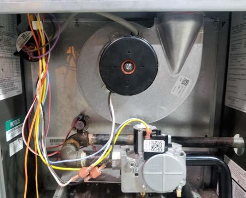
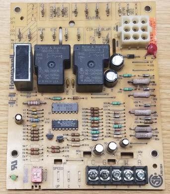
41 Chapter 11: Troubleshooting Scenario 4 A customer has called for service on a furnace that is not heating the home. The customer states that it sounds like the furnace is running, but it is not heating. The technician arrives and speaks with the homeowner about the problem. He checks the thermostat and finds that it is set to 73 degrees and that the room temperature is 62 degrees. The technician notes that the furnace is a 90% efficient hot surface ignition furnace located in a closet. He turns the service switch off and on to reset the IFC, which is in a hard lockout. The technician observes the furnace as it goes through the sequence of operations. The induced draft motor starts and closes the pressure switch. After a short delay, the gas valve is energized, and the flow of gas can be heard. The technician noted that the hot surface igniter did not come on at anytime during the sequence. He theorizes that it is a bad igniter or a bad IFC. Using a multimeter, the technician checks the resistance of the hot surface igniter and finds it within the specified range. While waiting for the furnace to make another attempt to ignite, the technician looks over the wiring diagram. He looks for the terminals on the IFC that provide 120V to the igniter, Figure The meter leads of the digital multimeter are then placed on the igniter terminals on the IFC. When the ignition sequence reaches the point at which the igniter should be energized, a reading of 0V is obtained. The technician concludes that the IFC is bad. The proper replacement is installed, referencing the schematic. The furnace is restarted, and the heating sequence is observed. The furnace runs as it should and the room temperature rises to the thermostat setpoint. The technician cleans the work area and places the door panels back on the furnace. He gives the homeowner a detailed explanation of the work performed and submits a neatly written invoice. The technician collects payment and leaves for his next call. Figure Gas Heating


42 GAS HEATING Be sure to check out additional titles available through Esco Press. Visit or call us for more information! Heating, Ventilation, Air Conditioning (HVAC) equipment is only as good as the installation. Studies show that the majority of HVACR equipment is not installed to manufacturer specifications, costing the consumer more money. This manual covers four areas critical to a system s performance including airflow, critical charging, psychrometrics, and combustion analysis. Combustion Analysis and Fuel Efficiency provides a full understanding of the combustion process, combustion test procedures, and the adjustments required to maximize fuel efficiency. Carbon Monoxide: A Clear and Present Danger addresses the hazards inherent in carbon monoxide generation and testing procedures. Additionally, it provides an overview of combustion analysis and the relation of building pressures to carbon monoxide generation. Heat Pumps; Operation, Installation, and Service is designed to provide the reader with a comprehensive overview of heat pump systems. The manual covers basic principles of operation, system components, air flow, defrost methods, balance point, auxiliary electric heat, electrical control wiring, refrigerant piping, installation, refrigerant charging, troubleshooting, dual fuel systems, and an introduction to geothermal systems. The intent of the book is to offer students and technicians information to build upon, in order to enhance their knowledge of the air conditioning and heating field, and more specifically, heat pumps. Electrical Theory and Application for HVACR provides students and practicing technicians with the information and knowledge necessary to accurately and safely diagnose and solve electrical system faults. Electrical Theory and Application for HVACR was written by HVACR instructors for HVACR instructors to simplify the instruction of electricity. ISBN:
PREVIEW COPY. Heating System Equipment. Table of Contents. Gas Heating Equipment...3. Oil Heating Equipment Electric Heating Systems...
 Heating System Equipment Table of Contents Lesson One Lesson Two Lesson Three Gas Heating Equipment...3 Oil Heating Equipment...19 Electric Heating Systems...35 Lesson Four Solid-Fuel Furnaces and Furnace...51
Combustion Safety. RESNET Conference San Antonio, TX February 27, Presented by Rich Moore Lightly Treading Energy & Design Denver, CO
 Combustion Safety RESNET Conference San Antonio, TX February 27, 2006 Presented by Rich Moore Lightly Treading Energy & Design Denver, CO Goals of this session Recognize the need for combustion safety
4.6 Advanced Propane Appliance Service and Troubleshooting Performance-Based Skills Assessment 2019
 4.6 Advanced Propane Appliance Service and Troubleshooting Performance-Based Skills Assessment Section One Section Two Task 3 Task 4 Section Three Task 3 Section Four Section Five Task 3 Task 4 Task 5
Oil Furnace USER S INFORMATION MANUAL FOR THE OPERATION AND MAINTENANCE OF YOUR NEW OIL-FIRED FURNACE
 Oil Furnace USER S INFORMATION MANUAL FOR THE OPERATION AND MAINTENANCE OF YOUR NEW OIL-FIRED FURNACE MODEL PO8LAA LOW-BOY NOTE TO INSTALLER: THIS MANUAL MUST BE LEFT WITH THE EQUIPMENT USER. MODEL PO8UAA
Fig. 1 - Unit PGD4, PGS4, WPG4
 OWNER S MANUAL 14 SEER Single -Package Air Conditioner and Gas Furnace System with R -410A Refrigerant Single Phase 2 to 5 Nominal Tons Three Phase 3 to 5 Nominal Tons PGD4andPGS4SeriesE,WPG4SeriesB Fig.
WARNING FIRE OR EXPLOSION HAZARD.
 2017 Lennox Industries Inc. Dallas, Texas, USA 506897-01 04/2017 Supersedes 10/2015 EL280DF SERIES GAS FURNACE Improper installation, adjustment, alteration, service or maintenance can cause property damage,
USER S INFORMATION MANUAL
 USER S INFORMATION MANUAL UPFLOW/HORIZONTAL & DOWNFLOW TWO STAGE INDUCED DRAFT GAS FURNACES Recognize this symbol as an indication of Important Safety Information If the information in this manual is not
In accordance with the Department of Labor and Industry s statute , Subd. 11,
 In accordance with the Department of Labor and Industry s statute 326.0981, Subd. 11, This educational offering is recognized by the Minnesota Department of Labor and Industry as satisfying 1.5 hours of
Carbon monoxide (CO) is a colorless, odorless gas that is the product of incomplete combustion of carbon-based fuels.
 is a colorless, odorless gas that is the product of incomplete combustion of carbon-based fuels.") Construction Concerns: Carbon Monoxide November 20, 2017 By Gregory Havel Carbon monoxide (CO) is a colorless, odorless gas that is the product of incomplete combustion of carbon-based fuels. The chemical
Construction Concerns: Carbon Monoxide November 20, 2017 By Gregory Havel Carbon monoxide (CO) is a colorless, odorless gas that is the product of incomplete combustion of carbon-based fuels. The chemical
Owner s Information Manual
 48ES---A and 48VL---A Comfort and Performance 13 and 14 SEER Single Packaged Air Conditioner and Gas Furnace System With Puron (R---410A) Refrigerant Single and Three Phase 2---5 Nominal Tons (Sizes 24---60)
Packaged Gas/Electric Units. Owner s Guide to Operating and Maintaining Your Gas/Electric Unit
 Packaged Gas/Electric Units Owner s Guide to Operating and Maintaining Your Gas/Electric Unit ELECTRICAL SHOCK HAZARD. FIRE OR EXPLOSION HAZARD Disconnect power at fuse box or service panel before performing
WARNING FIRE OR EXPLOSION HAZARD.
 2017 Lennox Industries Inc. Dallas, Texas, USA 506698-01 04/2017 Supersedes 10/2015 SL280DFV SERIES GAS FURNACE Improper installation, adjustment, alteration, service or maintenance can cause property
SUPER HIGH EFFICIENCY WATER HEATERS SUPPLEMENT TO INSTRUCTION MANUAL P/N (Replaces pg. 2 in instruction manual.) CONGRATULATIONS!
 CONGRATULATIONS!") SUPER HIGH EFFICIENCY WATER HEATERS SUPPLEMENT TO INSTRUCTION MANUAL P/N 238-44219-00 (Replaces pg. 2 in instruction manual.) CONGRATULATIONS! You have just purchased one of the finest water heaters on
SUPER HIGH EFFICIENCY WATER HEATERS SUPPLEMENT TO INSTRUCTION MANUAL P/N 238-44219-00 (Replaces pg. 2 in instruction manual.) CONGRATULATIONS! You have just purchased one of the finest water heaters on
P.O. Box , Dallas, TX USER'S INFORMATION MANUAL Single-Stage Warm Air Gas Furnaces
 P.O. Box 799900, Dallas, TX 75379-9900 USER'S INFORMATION MANUAL Single-Stage Warm Air Gas Furnaces This is a safety alert symbol and should never be ignored. When you see this symbol on labels or in manuals,
Have you downloaded the groovy show App? Search in the Apple App store or the Google Play Store for Everything Under the Sun
 Have you downloaded the groovy show App? Search in the Apple App store or the Google Play Store for Everything Under the Sun Don t forget to complete surveys at the end of each class. You can complete
ZG Shown READ ALL INSTRUCTIONS IN THIS MANUAL AND RETAIN FOR FUTURE REFERENCE WARNING
 See unit nameplate for manufacturer and address. 507258-04 7/2018 Supersedes 10/2017 ZG 036, 048, 060, 072, 074 (3, 4, 5 and 6 Tons) ZG 092, 102, 120, 150 (7-1/2, 8-1/2, 10 and 12 Tons) ROOFTOP UNITS ZG
OPERATING INSTRUCTIONS AND OWNER S MANUAL
 OPERATING INSTRUCTIONS AND OWNER S MANUAL MR. HEATER READ INSTRUCTIONS CAREFULLY: Read and follow all instructions. Place instructions in a safe place for future reference. Do not allow anyone who has
Installation Instructions Part No , Part No Part No
 Torsion-Flex Motor mount for PSC motors and Rigid-Mount for ECM motors Replacement Kit Cancels: New Installation Instructions Part No. 327752-401, Part No. 327753-401 Part No. 327754-401 IIK-310A-45-11
USER S INFORMATION MANUAL
 USER S INFORMATION MANUAL UPFLOW & DOWNFLOW/HORIZONTAL TWO-STAGE SAFETY CONDENSING GAS FURNACES Recognize this symbol as an indication of Important Safety Information IMPORTANT: All manufacturer products
VENTING CLEARANCES. BBT NORTH AMERICA Bosch Group. Bosch Water Heating 340 Mad River Park, Waitsfield, VT TWH-V-26 page 1 of 6 rev 01/06
 page 1 of 6 VENTING CLEARANCES The vents should not be obstructed and all joints properly fitted. Floors, ceilings and walls must be cut or framed to provide necessary clearance to vents. Metal strippings
ML180UH SERIES GAS FURNACE WARNING WARNING
 2017 Lennox Industries Inc. Dallas, Texas, USA 506525-01 04/2017 Supersedes 10/2015 ML180UH SERIES GAS FURNACE Improper installation, adjustment, alteration, service or maintenance can cause property damage,
SERVICE FACTS WARNING M801-SF-1C. Gas Furnaces Upflow & Downflow Induced Draft 1 Stage Heat Models: DISCONNECT POWER BEFORE SERVICING M801P040AU24AA
 SERVICE FACTS Gas Furnaces Upflow & Downflow Induced Draft Stage Heat Models: M80P00AU2AA M80P060AU2AA M80P060AU36AA M80P080BU36AA M80P080BU8AA M80P00BU36AA M80P00CU8AA M80P00CU60AA M80PDU60AA M80P0DU60AA
POWER VENTER SYSTEM. Model: PVO-300, PVO-600
 POWER VENTER SYSTEM Model: PVO-300, PVO-600 Included is one ETL and cetl listed Power Venter to be used primarily with a single 120VAC controlled oil fired furnace, boiler, or water heater. The PVO may
MANUAL WARNING FIRE OR EXPLOSION HAZARD. SL280UHNV SERIES WHAT TO DO IF YOU SMELL GAS:
 U S E R S I N F O R M AT I O N MANUAL 2017 Lennox Industries Inc. Dallas, Texas, USA SL280UHNV SERIES 507650-01 10/2017 Improper installation, adjustment, alteration, service or maintenance can cause property
FGR. Installation, Operation and Startup Instruction Manual FOR FLUE GAS RECIRCULATION SYSTEM. FGR-8 through FGR-22 (25 HP to 1000 HP)
") FGR Installation, Operation and Startup Instruction Manual FOR FLUE GAS RECIRCULATION SYSTEM FGR-8 through FGR-22 (25 HP to 1000 HP) Gas, Light Oil or Combination MANUFACTURED BY JOHN ZINK COMPANY, LLC
FGR Installation, Operation and Startup Instruction Manual FOR FLUE GAS RECIRCULATION SYSTEM FGR-8 through FGR-22 (25 HP to 1000 HP) Gas, Light Oil or Combination MANUFACTURED BY JOHN ZINK COMPANY, LLC
USER S INFORMATION MANUAL
 2017 Lennox Industries Inc. Dallas, Texas, USA 506737-01 04/2017 Supersedes 03/2017 USER S INFORMATION MANUAL EL195UHE SERIES GAS FURNACE Improper installation, adjustment, alteration, service or maintenance
Bosch 80% AFUE Gas Furnace BGS80 Model
 Bosch 80% AFUE Gas Furnace BGS80 Model 4-Way Multipoise Category I Fan-Assisted Furnace User's Information Manual 3124627 2 Bosch 80% AFUE Gas Furnace User's Information Manual Data subject to change 06.2018
COMBUSTION APPLIANCE SAFETY INSPECTION FOR VENTED APPLIANCES*
 COMBUSTION APPLIANCE SAFETY INSPECTION FOR VENTED APPLIANCES* *Vented appliances refer to natural draft appliances equipped with a barometric draft regulator or Category I appliances equipped with a draft
Overview of Gas Range Types
 Residential Gas Ranges Overview of Types How Carbon Monoxide is Emitted How They Operate Overview of Gas Range Types Rick Karg R.J. Karg Associates www.karg.com November 2001 2001 R.J. Karg Associates
INTRODUCTION. NOTE: Read the entire instruction manual before starting the installation. FIRE, EXPLOSION, ELECTRICAL SHOCK HAZARD
 Installation Instructions NOTE: Read the entire instruction manual before starting the installation. SAFETY CONSIDERATIONS Improper installation, adjustment, alteration, service, maintenance, or use can
EL195DFE SERIES GAS FURNACE WARNING
 2011 Lennox Industries Inc. Dallas, Texas, USA 506739 01 06/2011 EL195DFE SERIES GAS FURNACE Litho U.S.A. FIRE OR EXPLOSION HAZARD. Failure to follow safety warnings exactly could result in serious injury,
Gas Safety. Syllabus. For. Gas Appliance Service. Certificate of Qualification Examination. (Formerly Class C)
") Gas Safety Syllabus For Gas Appliance Service Certificate of Qualification Examination (Formerly Class C) 1. Prerequisites to obtain a gas appliance service certificate of qualification An applicant for
Gas Safety Syllabus For Gas Appliance Service Certificate of Qualification Examination (Formerly Class C) 1. Prerequisites to obtain a gas appliance service certificate of qualification An applicant for
SERVICE AND INSTALLATION MANUAL MODELS HDO(H) OIL FOR YOUR SAFETY
 OIL FOR YOUR SAFETY") Bousquet Technologies Inc. 2121, Nobel, Ste Julie, Quebec, Canada, J3E1Z9 SERVICE AND INSTALLATION MANUAL MODELS HDO(H) OIL Oil-Fired air heater for industrial and commercial use. FOR YOUR SAFETY Do not
Bousquet Technologies Inc. 2121, Nobel, Ste Julie, Quebec, Canada, J3E1Z9 SERVICE AND INSTALLATION MANUAL MODELS HDO(H) OIL Oil-Fired air heater for industrial and commercial use. FOR YOUR SAFETY Do not
POWER VENTER. Model: PVE Series
 POWER VENTER Model: PVE Series CONTENTS Typical Venting System Components... System Operation... Power Venter Sizing... Installation Safety Instructions... Installation of Power Venter... Connecting Power
Installer's Guide. WARNING: HAZARDOUS VOLTAGE - DISCONNECT POWER and DISCHARGE YCC-IG EB23D1-12
 Installer's Guide YCC-IG-12 18-EB23D1-12 Single Packaged Gas/Electric 13 SEER Convertible, 1½ - 5 Ton, 40-120 MBTU R-410A ALL phases of this installation must comply with NATIONAL, STATE AND LOCAL CODES
Combination Cooling/Gas Heat Package Units
 User s Manual Combination Cooling/Gas Heat Package Units YSC036E* YHC036E* YSC048E* YHC048E* YSC060E* YHC060E* YSC072E* YHC072E* YSC090E* YHC092E* YSC092E* YHC102E* YSC102E* YHC120E* YSC120E* July 2009
CUSTOMIZED TEACHER ASSESSMENT BLUEPRINT HVAC MAINTENANCE TECHNOLOGY. Test Code: 5937 Version: 01
 CUSTOMIZED TEACHER ASSESSMENT BLUEPRINT HVAC MAINTENANCE TECHNOLOGY Test Code: 5937 Version: 01 Specific competencies and skills tested in this assessment: Introduction to HVAC Identify HVAC systems Demonstrate
EL195UH SERIES GAS FURNACE WARNING
 2010 Lennox Industries Inc. Dallas, Texas, USA 506597 01 11/2010 EL195UH SERIES GAS FURNACE Litho U.S.A. FIRE OR EXPLOSION HAZARD. Failure to follow safety warnings exactly could result in serious injury,
USER S INFORMATION MANUAL
 USER S INFORMATION MANUAL UPFLOW & DOWNFLOW/HORIZONTAL CONDENSING GAS FURNACES SAFETY Recognize this symbol as an indication of Important Safety Information If not installed, operated and maintained in
HVA 140 RESIDENTIAL HEATING
 HVA 140 RESIDENTIAL HEATING PRESENTED AND APPROVED: AUGUST 9, 2012 EFFECTIVE: FALL 2013-14 Prefix & Number HVA 140 Course Title: Residential Heating Purpose of this submission: New X Change/Updated Retire
EL195UHE SERIES GAS FURNACE WARNING WARNING
 2012 Lennox Industries Inc. Dallas, Texas, USA 506737-01 12/2012 Supersedes 06/2011 EL195UHE SERIES GAS FURNACE Improper installation, adjustment, alteration, service or maintenance can cause property
OIL FURNACE USER S INFORMATION MANUAL FOR THE OPERATION AND MAINTENANCE OF YOUR NEW OIL-FIRED FURNACE
 58CLA OIL FURNACE USER S INFORMATION MANUAL FOR THE OPERATION AND MAINTENANCE OF YOUR NEW OIL-FIRED FURNACE NOTE TO INSTALLER: THIS MANUAL MUST BE LEFT WITH THE EQUIPMENT USER. WELCOME TO A NEW GENERATION
USER S INFORMATION MANUAL
 USER S INFORMATION MANUAL UPFLOW, DOWNFLOW, UPFLOW/HORIZONTAL & HORIZONTAL ONLY INDUCED DRAFT GAS FURNACES Recognize this symbol as an indication of Important Safety Information If the information in this
G61MPV SERIES GAS FURNACE WARNING
 2003 Lennox Industries Inc. Dallas, Texas, USA 504,809M 03/2009 Supersedes 06/2003 G61MPV SERIES GAS FURNACE Litho U.S.A. FIRE OR EXPLOSION HAZARD. Failure to follow safety warnings exactly could result
PVE SERIES POWER VENTER SYSTEM MANUAL
 PVE SERIES POWER VENTER SYSTEM MANUAL Contents Page I. Typical Venting System Components 2 II. System Operation 3 III. Power Venter Sizing 3,4 IV. Installation Safety Instructions 5,6 V. Installation of
LATTNER BOILER COMPANY 9.5 HP Low-NOx Installation and Start-Up Checklist for Dry Cleaners
 1 1. General Installation Information (to be completed by technician) Date installed: Location (city & state): Cleaner s name: National Board number (boiler): Installed by (company): Installed by (technician):
Experienced Worker Assessment Blueprint HVAC - Heating, Ventilation and Air Conditioning
 Blueprint HVAC - Heating, Ventilation and Air Conditioning Test Code: 0144 / Version: 02 Specific Competencies and Skills Tested in this Assessment: Electricity Demonstrate understanding of basic AC/DC
4.3 Installing Appliances and Interior Vapor Distribution Systems Performance-Based Skills Assessment 2016
 4.3 Installing Appliances and Interior Vapor Distribution Systems Performance-Based Skills Assessment 2016 Section One Task 1 Task 2 Task 3 Task 4 Task 5 Section Two Task 1 Task 2 Task 3 Task 4 Task 5
MODEL HS115-3, HS115-4 & HS115-5 WIRING DIAGRAM ADDENDUM
 TJERNLUND PRODUCTS, INC. 1601 Ninth Street White Bear Lake, MN 55110-6794 PHONE (800) 255-4208 (651) 426-2993 FAX (651) 426-9547 Visit our web site www.tjernlund.com MODEL HS115-3, HS115-4 & HS115-5 WIRING
EL296UHV SERIES GAS FURNACE WARNING WARNING
 2011 Lennox Industries Inc. Dallas, Texas, USA 506769 01 08/2012 Supersedes 10/2011 EL296UHV SERIES GAS FURNACE Improper installation, adjustment, alteration, service or maintenance can cause property
KG 092 SHOWN READ ALL INSTRUCTIONS IN THIS MANUAL AND RETAIN FOR FUTURE REFERENCE WARNING
 See unit nameplate for manufacturer and address. 507350-03 3/2016 Supersedes 9/2015 KG 024, 030, 036, 048, 060, 072, 074, 090 (2, 2-1/2, 3, 4, 5, 6 and 7-1/2 Tons) KG 092, 102, 120, 150 (7-1/2, 8 1/2,
Troubleshooting the Indoor AHU as a Standard Product
 Troubleshooting the Indoor AHU as a Standard Product Indoor Unit Circuit Board Indoor Unit Circuit Board Schematic The TECHs Need to Understand the Status and Fault Codes by LED Lights The control board
A hydronic system controls comfort by delivering heated or cooled fluid to the conditioned space through pipes.
 Introduction to Hydronics A hydronic system controls comfort by delivering heated or cooled fluid to the conditioned space through pipes. Hydronic heating systems use hot water or steam to deliver the
Product Data. 58EFA Horizontal Gas Furnace. 50, ,000 Btuh Input
 Product Data 58EFA Horizontal Gas Furnace 50,000 125,000 Btuh Input GAS SUPPLY MANUAL SHUTOFF VALVE SEDIMENT TRAP UNION Carrier presents the 58EFA, a dedicated horizontal gas furnace that excels in the
AS AS Australian Standard. Industrial fuel-fired appliances. This is a free 9 page sample. Access the full version online.
 AS 1375 2013 AS 1375 2013 Australian Standard Industrial fuel-fired appliances This Australian Standard was prepared by Committee AG-011, Industrial and Commercial Gas Fired Appliances. It was approved
MODELS LFP4218/LFP6018 TOP VENT GAS FIREPLACE
 MODELS LFP4218/LFP6018 TOP VENT GAS FIREPLACE PFS APPROVED FOR NATURAL GAS OR PROPANE GAS Z21.50-2014 If your plans do not allow for the venting system as outlined previously in the installing chimney/vent
Packaged Gas/Electric
 Packaged Gas/Electric Units Owner's Guide to Operating and Maintaining Your Gas/Electric Unit ELECTRICAL SHOCK HAZARD. FIRE OR EXPLOSION HAZARD Failure to follow this warning can result in Disconnect power
SLP98UH SERIES VARIABLE CAPACITY GAS FURNACE WARNING WARNING
 2015 Lennox Industries Inc. Dallas, Texas, USA 506443-01 01/2015 Supersedes 08/2012 SLP98UH SERIES VARIABLE CAPACITY GAS FURNACE Improper installation, adjustment, alteration, service or maintenance can
80% and 95% furnace models feature aluminized steel heat exchangers to conduct heat quickly and increase durability.
 FURNACES The Ameristar line of heating and cooling products offer you flexible and affordable options for HVAC equipment replacement. The Ameristar product line should complement the national brand you
INSTALLATION INSTRUCTIONS TXV Coils for Manufactured Housing EMA
 TXV Coils for Manufactured Housing EMA NOTE: Read the entire instruction manual before starting the installation. SAFETY CONSIDERATIONS Improper installation, adjustment, alteration, service, maintenance,
SUPER HIGH EFFICIENCY WATER HEATERS SUPPLEMENT TO INSTRUCTION MANUAL P/N (Replaces pg. 2 in instruction manual.) CONGRATULATIONS!
 CONGRATULATIONS!") SUPER HIGH EFFICIENCY WATER HEATERS SUPPLEMENT TO INSTRUCTION MANUAL P/N 238-51012-00 (Replaces pg. 2 in instruction manual.) CONGRATULATIONS! You have just purchased one of the finest w ater heaters on
SUPER HIGH EFFICIENCY WATER HEATERS SUPPLEMENT TO INSTRUCTION MANUAL P/N 238-51012-00 (Replaces pg. 2 in instruction manual.) CONGRATULATIONS! You have just purchased one of the finest w ater heaters on
USER'S MANUAL PGE Single Package Rooftop
 USER'S MANUAL PGE Single Package Rooftop Gas Heating/Electric Cooling Units Sizes 036-150 3 to 12-1/2 Tons NOTE TO INSTALLER: This manual should be left with the equipment owner. WARNING: If the information
USER S INFORMATION MANUAL
 2005 Lennox Industries Inc. Dallas, Texas, USA USER S INFORMATION MANUAL 13GCSX SERIES UNITS GAS PACKAGED UNITS (2 5 TONS) Armstrong # 38152A068 505,058M 05/09 Supersedes 08/05 Table of Contents Litho
Heating Maintenance and Repair
 Heating Maintenance and Repair Electric Furnace Electric Baseboard Gas Furnace Hydronic Heating Disclaimer The use of photos of tools and/or components which clearly indicate their manufacturer or brand
RSIF power venter USA CAN READ AND SAVE THESE INSTRUCTIONS! Installation and operation manual. Product information Chapters 1 + 2
 3002239 RSIF 2014-04-04 Installation and operation manual RSIF power venter READ AND SAVE THESE INSTRUCTIONS! Product information Chapters 1 + 2 Mechanical installation Chapter 3 Electrical installation
V SERIES HDR GAS RANGES
 SERVICE MANUAL ONE POWERFUL PACKAGE V SERIES HDR GAS RANGES TOPS Open Top Hot Top Griddle Top Work Surface BASES Standard Oven Convection Oven Cabinet Base - NOTICE - This manual is prepared for use by
2. Gas B. The column of hot gases, flames, and smoke rising above a fire; also called convection column, thermal updraft, or thermal column
 Fire Behavior Workbook Activities The following activities have been designed to help you. Your instructor may require you to complete some or all of these activities as a regular part of your fire fighter
INSTALLATION GUIDE Dual Fuel Ranges
 INSTALLATION GUIDE Dual Fuel Ranges Contents Wolf Dual Fuel Ranges......................... 3 Safety Instructions............................ 4 Dual Fuel Range Specifications.................. 5 Dual Fuel
USER S INFORMATION MANUAL SLP98UHV SERIES
 2017 Lennox Industries Inc. Dallas, Texas, USA 506443-01 04/2017 Supersedes 10/2015 USER S INFORMATION MANUAL SLP98UHV SERIES VARIABLE CAPACITY GAS FURNACE Improper installation, adjustment, alteration,
Columbia Boiler Company
 EMG Series Boilers Available in Natural Gas & Propane Rev 12012 Columbia Boiler Company PO Box 1070 Pottstown, PA 19464 Tel (610) 473-8457 Fax (610) 367-6800 Website www.columbiaboiler.com Email cbcsales@ptd.net
SAMPLE SPECIFICATION FOR RIELLO ARRAY MODULATING BOILER
 SAMPLE SPECIFICATION FOR RIELLO ARRAY MODULATING BOILER PART 1 GENERAL 1.01 RELATED DOCUMENTS A. ANSI Z21.13 American National Standard for Gas-Fired Low Pressure Steam and Hot Water Boilers B. ASME Section
HOME OWNER S INFORMATION Induced Combustion Gas Furnace
 HOME OWNER S INFORMATION Induced Combustion Gas Furnace NOTE TO INSTALLER: This manual must be left with the equipment user. USER: Please read all instructions in the manual and retain all manuals for
Glossary. Carbon Dioxide (CO 2
 Glossary AFUE (Annualized Fuel Utilization Efficiency): A measure of the efficiency of the heating unit (burner and boiler/ furnace) including standby losses during the off-cycles, given on an annual basis.
RESNET National Conference New Orleans, LA. February 16, 2009 Presented by Rich Moore Invisible Energy Denver, CO
 RESNET National Conference New Orleans, LA. February 16, 2009 Presented by Rich Moore Invisible Energy Denver, CO rgalenmoore1@msn.com This session will address the basics of combustion and the latest
OPERATING INSTRUCTIONS MANUAL (Please retain for future reference) FVN/P-400 INDIRECT FIRED SPACE HEATERS
 FVN/P-400 INDIRECT FIRED SPACE HEATERS") OPERATING INSTRUCTIONS MANUAL (Please retain for future reference) For FVN/P-400 INDIRECT FIRED SPACE HEATERS CERTIFIED FOR USE IN CANADA AND U.S.A. As per Standard ANSI Z83.7/CSA 21.4 2000 Gas Fired Construction
OPERATING INSTRUCTIONS MANUAL (Please retain for future reference) For FVN/P-400 INDIRECT FIRED SPACE HEATERS CERTIFIED FOR USE IN CANADA AND U.S.A. As per Standard ANSI Z83.7/CSA 21.4 2000 Gas Fired Construction
Safe Operation Manual. Honeywell IQ Force Gas Detector
 Safe Operation Manual Honeywell IQ Force Gas Detector Honeywell Analytics 800-663-4164 403-248-9226 Fax 403-575-3708 03JUN2012 P/N 50105843-047 Version 01 http://www.honeywell.com HONEYWELL IQ Force PERSONAL
a. CFCs. b. HCFCs. c. Pressurized nitrogen. d. Compressed dry air. 17. The state of the refrigerant leaving the condenser of a refrigeration system
 Core 1. Ozone in the stratosphere above the earth consists of: a. Molecules containing 3 oxygen atoms. b. Molecules of 2 oxygen atoms. c. Radioactive particles. d. Pollutants that have risen from ground
Manhattan Fire Protection District
 Section: RESCUE OPERATIONS Page 1 of 5 PURPOSE: This procedure is established to ensure proper detection and mitigation of carbon monoxide alarms and emergencies, and to provide a standard of response
RSIF Power Venter USA CAN. Product Information. ... Chapters Mechanical Installation. ... Chapter 3. Electrical Installation. ...
 Installation & Operating Manual RSIF Power Venter USA CAN Product Information... Chapters 1 + 2 Mechanical Installation... Chapter 3 Electrical Installation... Chapter 4 Start Up and Configuration... Chapter
COMBUSTION SAFETY BASICS
 COMBUSTION SAFETY BASICS Joe Konopacki Why Combustion Safety? Hydrocarbon fuels are hazardous Explosion or fire is possible Poor indoor air quality Exhaust byproducts are harmful or deadly Safe and efficient
CYLINDER NOT INCLUDED
 OPERATING INSTRUCTIONS AND OWNER S MANUAL Model # HS125NG / MH125LP / HS125LP READ INSTRUCTIONS CAREFULLY: Read and follow all instructions. Place instructions in a safe place for future reference. Do
USER MANUAL Gas Countertop Charbroilers
 Gas Countertop Charbroilers REVISED 2/209 382799 LAVA BRIQUETTE MODELS: 35CLCPG5NL, 35CLCPG24NL, 35CLCPG36NL, 35CLCPG48NL, 35CLCPG60NL, 35CLCPG72NL Congratulations on your purchase of Cooking Performance
Owner's Guide to Operating and Maintaining Your Gas/Electric Unit
 Packaged Gas Heat/Electric Cooling Units Owner's Guide to Operating and Maintaining Your Gas/Electric Unit ELECTRICAL SHOCK. FIRE OR EXPLOSION Failure to follow this warning could result in personal injury,
BEST DRAFT CONTROL: MANUAL DAMPERS IN MULTIPLE BOILER SYSTEMS
 BEST DRAFT CONTROL: MANUAL DAMPERS IN MULTIPLE BOILER SYSTEMS WHITEPAPER Decades of evolving codes have led to much confusion over how dampers can and cannot be used. Contrary to popular belief, manual
INDUCED DRAFT HIGHBOY AND COUNTERFLOW/HORIZONTAL GAS FURNACE
 INDUCED DRAFT HIGHBOY AND COUNTERFLOW/HORIZONTAL GAS FURNACE USERS INFORMATION MANUAL MODELS FOR USE WITH NATURAL GAS MHA-50N, MHA-75N, MHA-100N, MHA-125N, MDA-50N, MDA-75N, MDA-100N, MDA-125N FOR USE
LABORATORY SAFETY SERIES: Flammables & Explosives
 ERI Safety Videos Videos for Safety Meetings 2953 LABORATORY SAFETY SERIES: Flammables & Explosives Leader s Guide Marcom Group Ltd. INTRODUCTION TO THE PROGRAM Structure and Organization Information in
OPERATING INSTRUCTIONS MANUAL (Please retain for future reference) FVN/P-400 INDIRECT FIRED SPACE HEATERS
 FVN/P-400 INDIRECT FIRED SPACE HEATERS") OPERATING INSTRUCTIONS MANUAL (Please retain for future reference) For FVN/P-400 INDIRECT FIRED SPACE HEATERS CERTIFIED FOR USE IN CANADA AND U.S.A. As per Standard ANSI Z83.7/CSA 21.4 2000 Gas Fired Construction
OPERATING INSTRUCTIONS MANUAL (Please retain for future reference) For FVN/P-400 INDIRECT FIRED SPACE HEATERS CERTIFIED FOR USE IN CANADA AND U.S.A. As per Standard ANSI Z83.7/CSA 21.4 2000 Gas Fired Construction
User s Information Manual
 48AJ,AK,AW,AY020-060 Single-Package Rooftop Gas Heating Units with COMFORTLINK Controls and Scroll Compressors User s Information Manual NOTE TO INSTALLER This manual should be left with the equipment
KGA092 SHOWN READ ALL INSTRUCTIONS IN THIS MANUAL AND RETAIN FOR FUTURE REFERENCE WARNING
 See unit nameplate for manufacturer and address. 506380 01 11/2009 KGA024, 030, 036, 048, 060, 072 (2, 2 1/2, 3, 4, 5, and 6 Tons) KGA092, 102, 120, 150 (7 1/2, 8-1/2, 10, and 12 Tons) KGA180, 210, 240,
OIL FIRED WARM AIR FURNACE. Homeowner Instructions
 OIL FIRED WARM AIR FURNACE Homeowner Instructions Fire, explosion, asphyxiation and electrical shock hazard. Improper installation and operation could result in death or serious injury. Read this manual
Monitoring Flammable Vapors and Gases in Industrial Processes
 Monitoring Flammable Vapors and Gases in Industrial Processes Flammability Hazards Industrial fires and explosions happen more frequently than most people think. They cause downtime, property damage, injury
2.1 CO is a colorless, odorless, tasteless, non-irritating, toxic gas.
 FIRE TACTICS AND PROCEDURES March 15, 1997 (CO) 1. INTRODUCTION 1.1 Due to increased public awareness and the availability of carbon monoxide (CO) detectors for the home, the Fire Department is being called
DuPont Formacel Z-2. Safety and Handling of DuPont Formacel Z-2: Thermoplastic* Foam Extrusion Applications FOAM EXPANSION AGENT TECHNICAL INFORMATION
 DuPont Formacel Z-2 FOAM EXPANSION AGENT TECHNICAL INFORMATION Safety and Handling of DuPont Formacel Z-2: Thermoplastic* Foam Extrusion Applications Flammability of Formacel Z-2 and Other Alternative
about your house Assessing the Comfort and Safety of Your Home s Mechanical Systems
 about your house CE 28 k Assessing the Comfort and Safety of Your Home s Mechanical Systems The heating, ventilating and air conditioning (HVAC) systems are a vital part of every home. These mechanical
NOTE TO INSTALLER: THIS MANUAL MUST BE LEFT WITH THE EQUIPMENT USER.
 c_::_':_-_:_ r'" _" "_1 WARNING: If the information in this manual is not followed exactly, a fire or explosion may Iresult causing property damage, personal injury or [loss of life. m m m Do not store
4.5 Basic Propane Appliance Service and Troubleshooting Performance-Based Skills Assessment 2016
 4.5 Basic Propane Appliance Service and Troubleshooting Performance-Based Skills Assessment 2016 Section One Section Two Section Three Task 3 Section Four Task 3 Section Five Section Six Section Seven
PE MODEL WATER HEATERS SUPPLEMENT TO INSTRUCTION MANUAL P/N (Replaces pg. 2 in instruction manual.) CONGRATULATIONS!
 CONGRATULATIONS!") PE MODEL ATER HEATERS SUPPLEMENT TO INSTRUCTION MANUAL P/N 238-44219-00 (Replaces pg. 2 in instruction manual.) CONGRATULATIONS! You have just purchased one of the finest water heaters on the market today!
PE MODEL ATER HEATERS SUPPLEMENT TO INSTRUCTION MANUAL P/N 238-44219-00 (Replaces pg. 2 in instruction manual.) CONGRATULATIONS! You have just purchased one of the finest water heaters on the market today!
GPC PASTA PRO INSTALLATION & USER OPERATION MANUAL
 GPC-14/18/20 GPC PASTA PRO INSTALLATION & USER OPERATION MANUAL GPC-18 shown with optional rinse station. NOTICE! After installation of your equipment, immediately contact your local gas supplier to obtain
Calhoon MEBA Engineering School. Study Guide for Proficiency Testing Refrigeration
 Calhoon MEBA Engineering School Study Guide for Proficiency Testing Refrigeration 1. To prevent an injury when working with refrigerants, what safety precautions are necessary? 2. When halogens are in
RS Chimney Fan For Gas & Oil Applications. Installation & Operating Manual USA CAN
 Installation & Operating Manual 3000270 10.01 USA CAN RS Chimney Fan For Gas & Oil Applications 1200 Northmeadow Parkway, STE 180 Roswell, GA 30076 (770) 587-3238 (800) 255-2923 Fax (770) 587-4731 info@exhausto.com