1. Purpose of training package. HarmonAC training package
|
|
|
- Rolf Clark
- 5 years ago
- Views:
Transcription
1 1. Purpose of training package 1 / 1
2 1.1. Introduction 2 / 1
3 The purpose of Training package is to give knowledge to actors in MS who are going to train and license the Inspectors and Auditors of air conditioning systems. Training package was prepared by the help of questionnaire, which we made on base of information and knowledge produced by HARMONAC project. Training package is consisted of 7 presentations in PowerPoint: 1. Purpose of training package 2. Legal background 3. Air-conditioning systems basics 4. HARMONAC Inspection procedures 5. On-site data collection and analysis tools 6. Inspection report and recommendations 7. Examples of use of procedures on real systems / 1 3
4 1.2. Frequently asked questions 4 / 1
5 What is EPBD Directive and why was it introduced? The 160 million buildings in the EU use over 40% of Europe's energy and create over 40% of its carbon dioxide emissions, and this proportion is increasing. Under the Kyoto protocol, Europe is committed to reducing emissions and the Directive is intended to contribute to this. The cost effective savings potential is around 22% of present consumption in buildings. What is the present status of EPBD and where one can find updated information about it? Information on the EPBD by the European Commission is available here: You may also find of interest the details and information at: / 1 5
6 How much can this Directive reduce the carbon dioxide emmisions? According to the European Climate Change Programme, the Directive could deliver a reduction of up to 45 million tonnes of carbon dioxide by In order to meet the agreed Kyoto targets, the European Union should implement reductions of 330 million tonnes between 1990 and What is the purpose of Energy Performance Certificates? They serve two purposes: 1. Purchasers and renters of buildings will be able to compare the energy performance of different buildings before signing. 2. Building and energy managers will be able to compare their building's energy performance with other buildings. / 1 6
7 Can you explain the difference between an Asset Rating and an Operational Rating? An "Asset" Rating is: a calculated rating based on standard weather and building use An "Operational" Rating is: based on measured energy use Will the Directive be applied in the same way everywhere? Member States have discretion in how they implement the Directive as long as they satisfy its requirements. Depending on their legal and building control systems together with their existing infrastructure and practices, different countries will implement it in different ways. Over time, some procedures may become more widespread than others. / 1 7
8 How shall the limit of 12kW for the inspection of air-conditioning systems be interpreted? The EPBD requires (article 9) that Member States shall lay down the necessary measures to establish a regular inspection of air-conditioning systems of an effective rated output of more than 12 kw. Is inspection of the ventilation system required with the inspection of air conditioning systems? If a ventilation system has no thermal component, i.e., if it strictly serves only the purpose of providing fresh air to guarantee a suitable indoor air quality, the EPBD requirement for inspections does not apply. Shall the inspection also cover the distribution and control system of the air conditioning system? The definition of air-conditioning systems in article 2 of the EPBD refers to the whole system where the temperature of the air can be cooled, clearly including its distribution and control systems. / 1 8
9 What is the required frequency for the inspection of air conditioning systems? The frequency of inspection of air conditioning systems is not specified in the Directive. It is up to the Member States to specify and implement. What is an EPBD Independent Expert? Article 10 of the EPBD states that "Member States shall ensure that the certification of buildings, the drafting of the accompanying recommendations and the inspection of boilers and air conditioning systems are carried out in an independent manner by qualified and/or accredited experts, whether operating as sole traders or employed by public or private enterprise bodies". What does ''in an independent manner'' mean? In most cases self-certification is being linked to a government endorsed quality assurance accreditation framework so as to ensure that selfcertification is only undertaken by suitably qualified "competent persons". / 1 9
10 Why is it important that building certification and plant inspection is undertaken in an independent manner? If the EPBD is to achieve its objectives, it is of considerable important that prospective building purchasers or tenants are able to have confidence in energy performance certificates, plant inspection and the accompanying reports and recommendations. What qualifications will be required to become an Independent Expert? Article 10 of the EPBD suggests that practitioners must be "qualified and/or accredited experts". This implies that no specific formal qualification is required if the Independent Expert is "accredited". Each Member State is applying different qualification criteria. Source: / 1 10
11 1.3. Accredited training providers by country 11 / 1
12 Belgium Brussels region Organisation Department techniligies eet outils PEB Bruxelles Environment IBGE Bulgaria Technical University of Sofia Estonia France Energy Efficiency and Renewables Division Energy Department Ministry of Economic Affairs and Communications Chargee de mission Residentiel-Tertiaire Sous-Direction Demande et Maitrise de l'energie et des Mtieres Premieres Teledoc Italy ENEA Luxembourg Administration de l'environment Netherlands SenterNovem Norway Portugal Slovakia Norsk Energi The Norwegian Association for Ventilation and Energy Technology ADENE APIRAC EFRIARC Department of International Relations in Energy Energy Sector Ministry of Economy of the Slovak Republic Slovenia Ministry of the Environment and Spatial Planning / 1 12
13 2. Legal background 1 / 2
14 2.1. Energy Performance of Building Directive (EPBD) 2 / 2
15 Main issues covered by the EPBD the general framework for a methodology of calculation of the integrated energy performance of buildings (article 3); the application of minimum requirements on the energy performance of new buildings (article 4-5); the application of minimum requirements on the energy performance of large existing buildings that are subject to major renovation (article 4-6); energy performance certification of buildings (article 7); regular inspection of boilers (article 8) and of air-conditioning systems (article 9) in buildings and in addition an assessment of the heating installation in which the boilers are more than 15 years old; requirements for experts and inspectors for the certification of buildings (article 10), the drafting of the accompanying recommendations and the inspection of boilers and air-conditioning systems. / 2 3
16 Article 9 of EPBD Member States shall lay down the necessary measures to establish a regular inspection of air conditioning systems of an effective rated output of more than 12 kw. This inspection shall include: An assessment of the air-conditioning efficiency Sizing compared to the cooling requirements of the building Appropriate advice shall be provided to the users on: Possible improvement or replacement of the AC system Alternative solutions Of all the measures foreseen by EPBD, the inspection of AC systems is the one that has proved to be more difficult to implement / 2 4
17 Technical and contractual barriers to the diffusion of AC inspection Most AC system components (chillers, fans, pumps, etc.) are electrically-driven, but separate electricity metering (i.e., lighting, appliances, AC, etc.) is seldom available Calculation methods for assessing the AC energy demand are not as well established as those for winter heating National regulations for AC system inspection are generally still lacking Structure of energy service contracts: such contracts normally include operation and maintenance of AC systems, but who pays the electricity bills? / 2 5
18 Actions to promote the implementation of article 9 CEN standards Links with other legislative initiatives (promoted by Concerted Action) Research: EIE (Intelligent Energy for Europe) / 2 6
19 2.2. European standards (EN 15240, EN 15239) 7 / 2
20 The CEN standard In the frame of TC 156 Ventilation for buildings, two standards were accepted in 2007: 1. Energy performance of buildings - Guidelines for inspection of ventilation systems (EN 15239) 2. Energy performance of buildings - Guidelines for inspection of air conditioning systems (EN 15240). / 2 8
21 CEN Standard Ventilation for buildings-energy performance of buildings-guidelines for inspection of air-conditioning systems (EN 15240) The CEN draft standard EN is an important part of this effort. It was published in 2005 for "consultation" - that is, for comments to be received from Member States' standardisation bodies. The draft has been revised in the light of comments received and was published in This standard gives details for inspection of air conditioning systems, and of the associated air distribution and exhaust systems. It comprises a "normative" (mandatory) standard plus several "informative" annexes that describe recommended procedures, checklists etc. / 2 9
22 Scope Inspection of Ventilation Systems Mechanical, Natural, Hybrid Main parts normative Pre-inspection and documents collection Listing of the main elements necessary to identify and to collect to perform the inspection (building and system characteristics, locations, plans, use, performances required, ) Methodology of inspection on site according type of system Visual inspection of critical points Performances measurement for selected components (mechanical / hybrid systems) Sensibilisation for advice for improvements 10 / 2
23 The CEN standard Guidelines for inspection of AC systems The standard is made of 8 parts: 1. Scope 2. Normative and references 3. Terms and Definitions 4. Energy impacts of AC, justification of inspection improvements 5. Inspection methodology 6. Advice on alternative solutions and improvements 7. Frequency of inspection 8. Annexes / 2 11
24 The CEN standard Annexes Annex A Examples for the indication of subsystems of air conditioning systems Annex B Examples of inspection classes of air conditioning systems Annex C Features affecting the frequency and duration of inspection Annex D Checklist of pre-inspection information Annex E Recommendations for the extent of the inspection Annex F Examples of checklists indicating observations and appropriate actions or advice Annex G Inspection report, example of contents Annex H Energy impacts of air conditioning, justification of inspection and improvements / 2 12
25 3. Air Conditioning systems basics 1 / 3
26 3.1. Thermodynamic background 2 / 3
27 Air conditioning refers to treatment of indoor air (temperature, humidity) to produce thermal comfort. Air conditioning also involves cleanless and circulation of air to produce indoor air quality (IAQ). The best way to show air condition is Molier (h-x) diagram as shown on left. Shaded red area represent optimal winter conditions and blue area optimal summer conditions. / 3 3
28 Relative humidity ϕ= p p w P w partial pressure of water vapour P s saturation vapour pressure of water s Absolute humidity m x = m w A m w mass of water vapour m A mass of air x 0, 622 pw = p p w p atmospheric pressure 4 / 3
29 Mixing Air flows 1 and 2 are mixed together. Mixed air of condition 3 has new absolute humidity-x and enthalpy-h. x 3 = m x + m x m + m h 3 = m h + m h m + m / 3
30 Heating Air of condition 1 is heated to condition 2. Heat was needed to increase it's temperature. x h = x 2 1 ϑ >ϑ 2 1 ϕ <ϕ 2 1 > h / 3
31 Cooling Air of condition 1 is cooled to condition 2. Cold is needed to decrease it's temperature. x h = x 2 1 ϑ <ϑ 2 1 ϕ >ϕ 2 1 < h / 3
32 Adiabatic humidification Air of condition 1 is adiabatically humidified (h = const.) in humidification chamber with water sprayed into air. Consequence is cooled and more humid air in condition 2. x h > x 2 1 ϑ <ϑ 2 1 ϕ >ϕ 2 1 = h / 3
33 Steam humidification Air of condition 1 is humidified (T = const.) in humidification chamber with steam sprayed into air. Consequence is more humid air in condition 2. x h > x 2 1 ϑ >ϑ 2 1 ϕ >ϕ 2 1 > h / 3
34 Dehumidification Air of condition 1 is dehumidified. Consequence is cooled and less humid air in condition 2. x h < x 2 1 ϑ <ϑ 2 1 ϕ >ϕ 2 1 < h / 3
35 3.2. Air conditioning classification 11 / 3

36 12 / 3

37 13 / 3
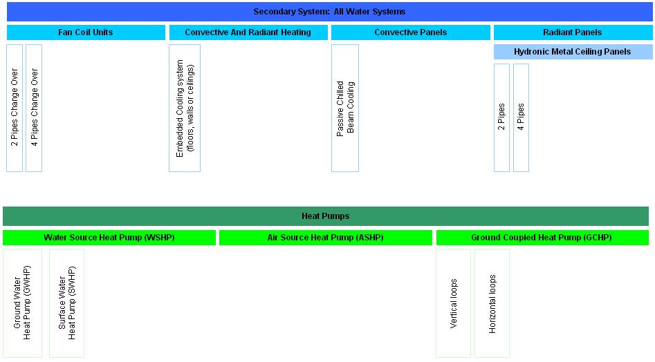
38 14 / 3
39 3.3. Air conditioning description 15 / 3


40 Packaged units LEGEND Water Air Refrigerant Expansion valve Condenser Fan Evaporator Compressor Cooling tower Zone equipped with a mobile packaged unit Source: 16 / 3


41 Packaged units LEGEND Water Air Refrigerant Expansion valve Condenser Fan Evaporator Compressor Cooling tower Zone equipped with a window unit Source: 17 / 3


42 Packaged units LEGEND Water Air Refrigerant Expansion valve Condenser Fan Evaporator Compressor Cooling tower Air cooled packaged system Source: / 3 18

 Source: http://www.icp-solutions.eu/index.php?")
43 Packaged units LEGEND Water Air Refrigerant Expansion valve Condenser Fan Evaporator Compressor Cooling tower Water cooled packaged system (water from network or natural source) Source: / 3 19


44 Packaged units LEGEND Water Air Refrigerant Expansion valve Condenser Fan Evaporator Compressor Cooling tower Water cooled packaged system (with cooling tower) Packaged unit source: Rooftop source: / 3 20


45 Split systems and variable refrigerant fluid (VRF) LEGEND Water Air Refrigerant Expansion valve Condenser Fan Evaporator Compressor Cooling tower Zone equipped with a split unit / 3 21


46 Split systems and variable refrigerant fluid (VRF) LEGEND Water Air Refrigerant Expansion valve Condenser Fan Evaporator Compressor Cooling tower Zone equipped with a multi-split unit Source: 7/jul/img_2243_lg_lm4865c21.jpg / 3 22


 / 3 Source:")
47 Chillers LEGEND Water Air Refrigerant Expansion valve Condenser Fan Evaporator Compressor Cooling tower Air cooled chiller with air handling unit (AHU) / 3 Source: Millenium, Ljubljana 23
 Source: ZPIZ, Ljubljana 24 / 3")
48 Chillers LEGEND Water Air Refrigerant Expansion valve Condenser Fan Evaporator Compressor Cooling tower Air cooled chiller with fan coil units (FCU) Source: ZPIZ, Ljubljana 24 / 3


49 Chillers LEGEND Water Air Refrigerant Expansion valve Condenser Fan Evaporator Compressor Cooling tower Air cooled chiller with chilled ceiling /


50 Chillers LEGEND Water Air Refrigerant Expansion valve Condenser Fan Evaporator Compressor Cooling tower Air cooled chiller with passive beams ems/chilled_beams/pkv/index.html / 3 26


51 Chillers LEGEND Water Air Refrigerant Expansion valve Condenser Fan Evaporator Compressor Cooling tower oducts/air_water_systems/ceili ng_induction_diffusers/did300 b/index.html Air cooled chiller with active beams Water cooled chiller with fan coil units (FCU) (water from network or natural source) / 3 27
52 Chillers LEGEND Water Air Refrigerant Expansion valve Condenser Fan Evaporator Compressor Cooling tower Water cooled chiller with air handling unit (AHU) (water from network or natural source) Water cooled chiller with air handling unit (AHU) (with cooling tower) / 3 28

 Water-cooled chiller source: www.york.com / 3 29")
53 Chillers LEGEND Water Air Refrigerant Expansion valve Condenser Fan Evaporator Compressor Cooling tower Water cooled chiller with air handling unit AHU (with cooling tower) Water-cooled chiller source: / 3 29

54 Water loop heat pump LEGEND Water Air Refrigerant Expansion valve Condenser Fan Evaporator Compressor Cooling tower Water loop heat pumps om/mcquay/producti nformation/wshp/w SHPpage / 3 30
55 The cooling towers LEGEND Water Air Refrigerant Expansion valve Condenser Fan Evaporator Compressor Cooling tower Dry cooling tower Wet cooling tower / 3 31

56 The cooling towers LEGEND Water Air Refrigerant Expansion valve Condenser Fan Evaporator Compressor Cooling tower Wet/Dry cooling tower Cooling tower source: / 3 32
57 Mechanical ventilation and air handling units (AHU) LEGEND Water Air Refrigerant valve Fan Pump Damper Filter Command Ventilation system with CO 2 detector without cooling Air Handling Unit- Constant Air Volume / 3 33

58 Mechanical ventilation and air handling units (AHU) LEGEND Water Air Refrigerant valve Fan Pump Damper Filter Command Air Handling Unit - Variable Air Volume AHU source: / 3 34
59 4. HARMONAC Inspection procedures 1 / 4
60 The inspection methodology is divided into: Pre-inspection Inspection Packaged air conditioning systems Centralised air conditioning systems Audit / 4 2
61 4.1. Pre-inspection 3 / 4
62 Pre-inspection methodology Pre-inspection methodology comprises the collection of important information. The information is collected on the structural and mechanical components that affect building energy use and the operational characteristics of the facility. Evaluating energy use and AC system before inspection/audit helps identify potential savings and makes best use of time spent. The aim of the pre-inspection is recognition with the building (zone), with the treated AC system from the documentation and with the service/maintenance done. / 4 4

63 AC device and AC system boundaries / 4 5
64 Pre-inspection methodology Pre-inspection methodology consists of : Building design (project) documentation, AC system documentation, a. Project documentations b. Technical documentation c. Operation, maintenance and services practices (documents) d. Reports of the measurements e. Relevant changes, zone types, occupancy schedules f. Utility energy data review / 4 6
65 4.1.1 Building design (project) documentation 7 / 4


66 PI1-a: Zone description Name of Building Location of Building Exposure Number of storeys Original year of construction 8 / 4


67 PI1-b: Zone description Hospitals Hotels, bar and restaurant Trade Offices Houses Education 9 / 4


68 PI2-a: List of documention Building Energy performance certification Report of the last regular inspection of the system As-built file, if as-built file does not exist, project for execution Complaints Book of operation, service and maintenance 10 / 4


69 PI2-b: List of documention Is there a BMS system installed? Energy saving measures already applied Calibration and maintenance operations carried out on control systems and sensors, or BMS systems and sensors. Commissioning information Balancing Monitoring station which is used to continually observe the performance of equipment (eg. submetering, dedicated loggers etc) 11 / 4

70 PI3: Photos / sketch of the building Photos / Sketches of the building 12 / 4
![PI4: General zone data Volume conditioned [m3] Number of storeys Area conditioned](/docs-images/88/114718479/images/71-3.jpg "[m2] Zone ID Installed lighting and appliances power [W/m2] Main use of zone 13 /")
71 PI4: General zone data Volume conditioned [m3] Number of storeys Area conditioned [m2] Zone ID Installed lighting and appliances power [W/m2] Main use of zone 13 / 4

![U-value [W/m²K] Glazing type](/docs-images/88/114718479/images/72-2.jpg "Frame type Roof / ceiling")
![type and U-value [W/m²K]](/docs-images/88/114718479/images/72-3.jpg "Floor Window g-value Window")

72 PI5-a: Construction datails Exterior wall type and U-value [W/m²K] Glazing type Frame type Roof / ceiling type and U-value [W/m²K] Floor type and U-value [W/m²K] Window g-value Window (frame+glazing) U-value [W/m²K] Shading device 14 / 4

![Window area [m2] Roof /](/docs-images/88/114718479/images/73-2.jpg "ceiling area [m2] Floor")
73 PI5-b: Construction datails Wall area [m2] Window area [m2] Roof / ceiling area [m2] Floor area [m2] 15 / 4

74 IP6: Building mass and air tightness / leakage Building thermal mass Ventilation rate 16 / 4


75 IP7: Occupancy schedule Lighting and appliances Cleaning schedule Other (specify) HVAC operation Opening time 17 / 4

76 IP8: Exceptions core hours / Building opening Exceptions Core hours 18 / 4
77 4.1.2 AC system documentation 19 / 4


78 PI9a: HVAC system description Cold Generator Records of maintenance Documentation of composition of HVAC system Records of any issues or complaints that have been raised concerning the indoorcomfort conditions achieved in the treated spaces Required processes System type (eg. VRF, VAV etc.) 20 / 4


79 PI9b: HVAC system description Set points Control Terminal Units AHU 21 / 4


80 IP10a: Original enviromental tal conditions Cooling design conditions Heating design conditions Design Cooling load Design Heating load 22 / 4


81 IP10b: Original enviromental tal conditions Minimum outside air supplied to zones Maximum outside air supplied to zones Total air flow rate supplied to zones Total air flow rate extracted from zones Fresh air flow rate per occupant Air extraction for lighting 23 / 4


82 PI11a: Design loads Lighting design Level Lighting type and installed power Lighting type of control 24 / 4


83 PI11b: Design loads Other electrical equipment Heating and cooling equipment Air handling units with main fan, exhaust fan and pumps Fans associated to terminal units Pumps not already included in air handling units (distribution, recovery ) 25 / 4


")

84 PI12: Power / Energy information Required cooling capacity Required heating capacity Expected energy use for cooling (including fans and pumps) Expected energy use for heating (including fans and pumps) 26 / 4


85 PI13-a: Heating equipment Oil boiler Oil condensing boiler Gas boiler Gas condensing boiler District heating transfer station 27 / 4


")

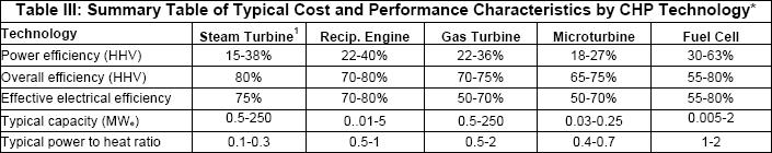
86 PI13-b: Heating equipment CHP (combined heat and power system) Biomass boiler Coal-fired boiler Electrical storage heating Heat pump 28 / 4
 5.")
87 Friday Sunday Tuesday Thursday Saturday Monday 21.April 1.May 14.May 28.May 7.June 21.June 1.July 14.July 28.July 7.August Wednesday Monday PI14: Storage and control system 90 Storage tank included Holiday set back Night set back Holiday cut-off C (6:00) 5.4 (18:00) 6.4 (6:00) 6.4 (18:00) 7.4 (6:00) 7.4 (18:00) 8.4 (6:00) 8.4 (18:00) 9.4 (6:00) 9.4 (18:00) 10.4 (6:00) 10.4 (18:00) 11.4 (6:00) 11.4 (18:00) Night cut-off Hours Thursday Saturday 29 Day 7.April 14.March 28.March 1.March 1.January 14.January 28.January 7.February 21.February C Weekend set-back Weekend cut-off Month C / 4

88 PI15-a: Refrigeration equipment Type Cooling capacity Nominal electrical power COP / EER Documentation Refrigerant fluid 30 / 4

 Total fan")

89 PI15-b: Refrigeration equipment Operation time estimated Control mode Storage (cold) Total fan power Volume/temperature Cooling tower pump power 31 / 4

90 PI16-a: Air handling unit Exhaust fan Pre-heater Cooling coil Heat recovery unit Supply fan Filters 32 / 4

91 PI16-b: Air handling unit Recirculation flap Reheater Humidifier Humidity recovery 33 / 4


92 PI17: Fluid distribution Documentation Pressure drop Main Volume flow rate Fluid temperature Heat carrier fluid Control mode Insulation 34 / 4
 Nominal air flow")
 3590 4")
 1440 Sensible")
 29 radiant ceiling Carat model type")
 chilled beams Caret H-31 10 0,015")
93 PI18-a: Heating and cooling delivery elements for air distribution (VAV box) Nominal air flow (m3/h) 215 fan coil Available static pressure - 2 pipe coil system heating capacity (W) tube coil system heating capacity (W) 2520 Total cooling capacity (W) 1440 Sensible cooling capacity (W) 1020 radiant floor Sound level (dba) 29 radiant ceiling Carat model type Connection diameter (mm) Minimum Flow (active or passive) chilled beams Caret H , ,03 35 / 4


94 PI18-b: Heating and cooling delivery air heat exchanger induction unit surface cooling direct expansion unit (reversible or not) 36 / 4
 Auxiliary energy Cooling (Type of fuel) 37 /")
95 PI19: Energy supply to the system Heating (Type of fuel) Auxiliary energy Cooling (Type of fuel) 37 / 4
 Auxiliary energy Cooling (Type of fuel) 38 / 4")
96 PI20: Energy supply to the building Heating (Type of fuel) Auxiliary energy Cooling (Type of fuel) 38 / 4

97 PI21:Annual energy consumption of the system Total electrical Heating fuels Total fuel costs Total electrical cost including the peak cost in /kw 39 / 4
98 November December November December PI22:Total heating, cooling, electrical, lightning cooling Heating January February March April May June July August September October Month Electricity kwh MWh Heating fuels Total fuel costs kwh January February March April May June July August September October November December Month Total electrical Water Total electrical cost including the peak cost in /kw m January February March April May June July August September October November December January February March April May June July August September October Month month 40 / 4
99 4.2. Inspection 41 / 4
100 Inspection methodology Article 9 exists to produce procedures to determine whether there is actually a need for the cooling equipment being assessed and, if there is, to reduce the energy used for the cooling process as far as is practically possible. The inspection procedures tested in this document will eventually provide a range of field-trialled methodologies designed to allow Member States to maximize the opportunity cost/benefit ratios of their inspection procedures within their own overall strategies for carbon reduction. The inspection methodologies to be tested here range from simple visual observations of the plant and other visual indicators such as refrigerant sight glasses, fixed refrigerant pressure or temperature gauges; through to detailed assessments using sophisticated field-testing equipment. In particular, the work will take extensive energy consumption readings to assess how changes in the system might affect the overall energy consumption. / 4 42
101 Pre-inspection methodology Pre-inspection methodology consists of : Packaged system inspection checklist, Centralized system inspection component checklist, / 4 43
102 4.2.1 Packaged system inspection checklist 44 / 4


103 P1: Revision of available documentation from pre- inspection Review available documentation from pre-inspection Locate the plant and compare details with pre-inspection data / 4 45


104 P2: Electrical supply to A/C system Locate electrical supply or supplies to all the components of the A/C system and install VA logger(s). Check indoor units not fed off local supply 46 / 4


105 P3: Review current inspection and maintenance regime Compare size with imposed cooling loads cooling kwh January February March April May June July Month August September October November December Compare any records of use of the package, or submetered energy consumption with expected hours of use per year for the plant, or with appropriate energy benchmarks For outdoor units: Obtain condensing pressure and off-coil T. For indoor units: Obtain evaporator approach T 47 / 4


106 P4-a: Description of outdoor unit Locate outdoor plant Check for signs of refrigerant leakage. Check that refrigeration plant is capable of providing cooling by assessing temperature difference, [1], and/or refrigerant temperature or pressure gauges (where readily visible) Check location of outdoor unit for proximity to local sources of heat, such as discharged air from other units or warm air exhausts. 48 / 4


107 P4-b: Description of outdoor unit Do heat exchangers have adequate free access to outdoor air? Check for debris and size of openings in enclosures Is cleaning or repair needed? Spot measurements of electrical power consumption of outdoor units to check for changes in consumption before/after cleaning of grilles, heat exchangers and filters. 49 / 4


108 P5-a: Assessment of zoning, controls and senzors Assess zoning in relation to factors such as local levels of internal gain, orientation and exposure to solar radiation. Check the current indicated weekday and time of day on controllers against the actual time. Note the set on and off periods Identify and assess zone heating and cooling temperature control sensors. 50 / 4


109 P5-b: Assessment of zoning, controls and senzors Note the set temperatures in each zone for heating and cooling in relation to the activities and occupancy of the zones and spaces Note provision of controls or guidance to inhibit use of equipment while windows are open Type, age and method of capacity control of the equipment 51 / 4
110 4.2.2 Centralized systems inspection component checklist 52 / 4

 Locate electrical supply or supplies")
.")
111 C1-a: System documentation Locate relevant plant and compare details Review current inspection and maintenance regime. (compare with manufacturers recommendations, and recommended industry standard maintenance schedules) Locate electrical supply or supplies to all the components of the A/C system, including fans if part of cooling delivery, and install VA logger(s). Check supplies to all components are monitored. 53 / 4


112 C1-b: System documentation cooling Estimate Specific Fan Power of relevant air movement systems kwh January February March April May June July Month August September October November December Time of maintenance actions for comparison with the fan power VA before and after maintenance items completed. Compare system size with imposed cooling loads (Report result of comparison with design loads estimations and any other calculations of cooling loads). 54 / 4. Q demand [kw] January February March April May June July August October November December Compare any records of air conditioning plant usage or submetered energy consumption with expected hours of use per year for the plant, or with appropriate energy benchmarks

113 C2: Refrigeration plant Locate refrigeration plant and check operation. Visual appearance of refrigeration plant and immediate surrounding area Check that refrigeration plant is capable of providing cooling by assessing temperature difference, and observing the refrigerant sight glass[1], and/or refrigerant temperature or pressure gauges (where readily visible) [1] This is not valid for many systems where the refrigerant has been changed in retrofits, or with modern blends. Check type, rating and operation of distribution fans and pumps 55 / 4


114 C3:Outdoor heat rejection equipment Check for the correct rotation of fans. (Monitor power consumption of fans in use and check before/after cleaning heat rejection units) Visual check of the condition and operation of outdoor heat rejection units. Check for signs of refrigerant leakage. Check for obstructions to airflow through heat rejection heat exchangers. 56 / 4
 Check air inlets and outlets for")


115 C4: Indoor units (split and distributed systems) Check air inlets and outlets for obstructin. Visually check the condition and operation of indoor units. Check for signs of refrigerant leakage. Check condition of intake air filters. Check for the correct rotation of fans Check for obstructions to airflow through the heat exchangers. 57 / 4


116 C5: Air delivery systems (in treated spaces) Review any evidence that occupants find the air delivery arrangement unacceptable. Assess the positioning and geometry of air supply openings in relation to extract openings. Review air delivery openings, grilles or diffusers, and route by which air is extracted from the spaces. Assess the controllability of a sample number of terminal units 58 / 4


117 C6: Air delivery systems (in air handling units) Check filter changing or cleaning frequency. Fan type and method of air speed control. Examine refrigeration heat exchangers for signs of refrigerant leakage. Assess the current state of cleanliness or blockage of filters (check need for cleaning or replacement) Power consumption of fan in operation, along with air flow rates and area of ductwork Assess the fit and sealing of filters and housings. Note the condition of filter differential pressure gauge. Examine heat exchangers for damage, or significant blockage by debris or dust (check need for cleaning or replacement). 59 / 4


118 C7: Air delivery systems (at audoor air inlets) Check for obstructions or blockages to inlet grilles, screens and pre-filters. Maintenance operations carried out on air delivery systems Check location of inlets for proximity to local sources of heat, or to air exhausts. 60 / 4


119 C8-a: System controls Assess zoning in relation to factors such as local levels of internal gain, orientation and exposure to solar radiation. Note whether a dead band is or can be set between heating and cooling. Check control basis Note the current indicated weekday and time of day on controllers against the actual time. Identify and assess zone heating and cooling temperature control sensors. Set temperatures in each zone for heating and cooling in relation to the activities and occupancy of the zones and spaces. Note the set on and off periods (for weekday and weekend if this facility is available with the timer). 61 / 4
 and the method of refrigeration capacity control.")
 /auto(time)/seasonal or zone temp) Assess how ancillary system components such as pumps")
120 C8-b: System controls Assess how reheat is undertake in the system, and in particular how the building is brought up to temperature in the morning Assess the refrigeration compressor(s) and the method of refrigeration capacity control. Assess means of modulating or controlling air flow rate through air supply and exhaust ducts. Check actual control basis (hand(manual) /auto(time)/seasonal or zone temp) Assess how ancillary system components such as pumps and fans are controlled when the system is off. 62 / 4
121 5. On-site data collection and analysis tools 1/ 5
122 5.1. Data collection from AC systems on-site 2/ 5


123 Required Audit Equipment Lightmeter used to measure illumination levels in facilities, allows direct analysis of lighting systems and comparison with recommended light levels. Air flow devices used to measuring air flow from air conditioning or ventilating ducts. Typical airflow measuring devices include a velometer, an anemometer, or an airflow hood. Environmental parameters 3/ 5 used to measure temperature, humidity, CO2, CO, velocity, etc.


124 Required Audit Equipment Infrared Cameras used to find overheated electrical wires, connections, neutrals, circuit breakers, transformers, motors and other pieces of electrical equipment. They can also be used to find wet insulation, missing insulation, roof leaks, and cold spots. Energy Analyzers used for determining the power consumption and power factor of individual motors and other inductive devices. Combustion Analyzer used for estimating the combustion efficiency of furnaces, boilers, or other fossil fuel burning machines. 4/ 5


125 Required Audit Equipment Miniatures Data loggers used to record measurements of temperature, relative humidity, light intensity, light on/off, and motor on/off. Gauge Manifold used to check the pressures of the refrigerant inside the system. Analyzers can also be used to Safety Equipment 5/ 5 identify refrigerant leaks. Flow meter ideal for flow surveys and closed pipe applications where non-invasive measurement of liquids is required. vital precaution for any energy auditor


126 Hot & cold water flows and T metering and recording 6


127 Electrical power & automatic recording Recording PC or data logger 7/ 5


128 Energy counter Energy counter Chilling group feeder Floor feeder 8/ 5

129 Meteo station Weather data acquisition 9/ 5
130 5.2. Benchmark 10/ 5
131 BENCHMARK is used to compute the "theoretical" (or reference ) consumptions of the building, supposed to be equipped with a typical HVAC system, including air quality, temperature and humidity control. The building is seen as a unique zone, described by very limited number of parameters. This first simulation tool should help the auditor in getting, a very first impression about the performances of the system and a very first interpretation of the recorded consumptions. / 5 11
132 The outputs, inputs and parameters must be selected according to the specific needs of the user. The main outputs of the tool presented here are: air quality and hygrothermal comfort achievements, global power and energy consumptions, HVAC components specific demands and performances of the mechanical equipments. The main inputs are: weather data, nominal occupancy loads (in W/m²), occupancy and installation functioning rates, comfort requirements and control strategies. The main parameters are: dimensions, orientation and general characteristics of the building envelope and sizing factors of the main HVAC components. / 5 12

133 Main control panel (BENCHMARK v1.2.) / 5 13
134 Building description control panel / 5 14
135 5.3. Simaudit 15/ 5
136 Global monthly consumptions are often insufficient to allow an accurate understanding of the building s behaviour. SIMAUDIT offers a larger range of available HVAC equipment and offers to calibrate the simulation model by tuning parameters. / 5 16
137 The building is still seen as a unique zone. The system includes an equivalent global AHU and several types of TU (radiators, fan coils, cooling ceiling, etc.). After having been calibrated to the recorded data, the baseline model can be used to identify the main energy consumers (lights, appliances, fans, pumps ) and to analyze the actual performance of the building. / 5 17
138 5.4. Cat tool 18/ 5
139 This tool provides guidance to the Building Owner, Inspector and/or Auditor on the potential for reducing the cooling demand of the building being Inspected or Audited. It achieves this by illustrating how the RELATIVE building heating and cooling DEMAND might be altered in percentage terms by changing certain elements of the building design or operation. The CAT does not cover all possible permutations of criteria and parameters, but should provide a good first guide towards the RELATIVE influence of various building aspects on the monthly and annual heating and cooling DEMANDS. / 5 19

140 Building Criteria Building criteria refer to those aspects of your building that are fixed and not easily subject to change. The selections you make below will define the search criteria against which items in the database will be matched. / 5 20
141 Building Parameters Building parameters refer to those aspects of the building which are generally under control of the occupants or can be varied in some way without major costs. Entering indicative values for each parameter for the building being assessed will enable this value to be used as a reference in the relevant graph shown on the results page. If no value is entered, the graphs default to a value the authors have taken to represent an average for that particular parameter. / 5 21

142 System Parameters In order to accurately compare heating and cooling energy, as well as calculating potential carbon emissions savings, you will need to estimate the relative efficiency of the plant and equipment used to supply the building's heating and cooling demand. These values are usually very difficult to obtain with any accuracy so you should ensure you test the likely range in the building being assessed to estimate the sensitivity of any recommendations to reasonable variations in these figures. / 5 22
 demand as a function")

143 CAT tool results Heating (cooling) demand as a function of U-value Heating (cooling) demand as a function of Ventilation rate / 5 23
144 5.5. AC Cost 24/ 5
145 AC-cost is a simple sheet that aims at helping to understand the status of the operation of an air conditioning plant through the analysis of the history of running costs bills including energy, water, maintenance. Moreover, we propose to estimate the possible savings through some energy saving opportunities. The data you need For the existing plant you can retrieve the information required: Starting from design plans and documents for the building and for the air conditioning plant From the monitoring system if present: electricity measurements for the air conditioning system, water consumption at the cooling tower can be recorded and saved all along the life of the system Electricity bills Maintenance contracts, logbook and extra bills. / 5 25
146 What you can calculate Four projects of retrofit or renovation are proposed: Replacement of the system of cooling production with a better efficiency Replacement of the system of cooling production with a lower capacity system (better or not efficiency) Conversion for air system using air handling units from constant volume type to variable air type Benefit from the use of free cooling. / 5 26

147 27 / 5
148 6. Inspection report and recommendation 1/ 6
149 6.1. Inspection report principles 2/ 6
150 Reporting Post-site work is a necessary and important step to ensure the preliminary audit will be useful. The auditor needs to evaluate the information gathered during the site visit, research possible Energy Conservation Opportunities (ECO s), organize the audit into a comprehensive report, and make recommendations on improvements. The report from the audit, with possible ECO s, should be used as the basic input for subsequent more detailed audits. / 6 3
151 6.2. Reporting of Energy Conservation Opportunities (ECOs) 4/ 6
152 General classification of ECOs Qualitative and quantitative information gathered in the Pre-inspection and Inspection phases should lead to actions, including a selection of applicable and cost-effective ECOs: Envelope and loads Plant Operations and Management (O&M) / 6 5
153 ECO list Envelope and loads Solar gain reduction / daylight control improvement Ventilation / air movement / air leakage improvement Envelope insulation improvement Other actions aimed at load reduction Plant BEMS and controls / miscellaneous Cooling equipment / free cooling Air handling / heat recovery / air distribution Water handling / water distribution Terminal units System replacement (in specific limited zones) O&M Facility management General HVAC system Cooling equipment Fluid (air and water) handling and distribution 6 / 6
154 Envelope and loads E1. Solar gain reduction / daylight control improvement E1.1 Install window film or tinted glass E1.2 Install shutters, blinds, shades, screens or drapes E1.3 Operate shutters, blinds, shades, screens or drapes E1.4 Replace internal blinds with external systems E1.5 Close off balconies to make sunspace/greenhouse E1.6 Modify vegetation to save energy E1.7 Maintain windows and doors E2. Ventilation / Air movement / Air leakage improvement E2.1 Generate possibility to close/open windows and doors to match climate E2.2 Ensure proper ventilation of attic spaces E2.3 Optimise air convective paths in shafts and stairwells E2.4 Correct excessive envelope air leakage E2.5 Roll shutter cases: insulate and seal air leaks E2.6 Generate possibility of night time overventilation E2.7 Add automatic door closing system between cooled and uncooled space E2.8 Replace doors with improved design in order to reduce air leakage / 6 7
155 Envelope and loads E3. Envelope insulation E3.1 Upgrade insulation of flat roofs externally E3.2 Upgrade attic insulation E3.3 Add insulation to exterior walls by filling cavities E3.4 Add insulation to exterior wall externally E3.5 Add insulation to basement wall externally E3.6 Upgrade insulation of ground floor above crawl space E3.7 Locate and minimize the effect of thermal bridges E3.8 Cover, insulate or convert unnecessary windows and doors E3.9 Use double or triple glaze replacement E4. Other actions aimed at load reduction E4.1 Reduce effective height of room E4.2 Use appropriate colour exterior E4.3 Employ evaporative cooling roof spray E4.4 Provide means of reducing electrical peak demand through load shedding E4.5 Replace electrical equipment with Energy Star or low consumption types E4.6 Replace lighting equipment with low consumption types E4.7 Modify lighting switches according to daylight contribution to different areas E4.8 Introduce daylight / occupation sensors to operate lighting switches E4.9 Move equipments (copiers, printers, etc.) to non conditioned zones 8 / 6
156 Plant P1. BEMS and controls / Miscellaneous Envelope insulation P1.1 Install BEMS system P1.2 Define best location for new electrical and cooling energy meters P1.3 Modify controls in order to sequence heating and cooling P1.4 Modify control system in order to adjust internal set point values to external climatic conditions P1.5 Generate the possibility to adopt variable speed control strategy P1.6 Use class 1 electrical motors P1.7 Reduce power consumption of auxiliary equipment / 6 9
157 Plant P2. Cooling equipment / Free cooling P2.1 Minimise adverse external influences (direct sunlight, air flow obstructions, etc.) on cooling tower and air cooled condenser (AHU, packaged, split, VRF systems) P2.2 Reduce compressor power or fit a smaller compressor P2.3 Split the load among various chillers P2.4 Repipe chillers or compressors in series or parallel to optimise circuiting P2.5 Improve central chiller / refrigeration control P2.6 Replace or upgrade cooling equipment and heat pumps P2.7 Consider feeding condenser with natural water sources P2.8 Apply evaporative cooling P2.9 Consider using ground water for cooling P2.10 Consider indirect free cooling using the existing cooling tower (free chilling) P2.11 Consider Indirect free cooling using outdoor air-to-water heat exchangers P2.12 Consider the possibility of using waste heat for absorption system P2.13 Consider cool storage applications (chilled water, water ice, other changing materials) P2.14 Consider using condenser rejection heat for air reheating / 6 10
158 Plant P3. Air handling / Heat recovery / Air distribution P3.1 Reduce motor size (fan power) when oversized P3.2 Relocate motor out of air stream P3.3 Use the best EUROVENT class of fans P3.4 Use the best class of AHU P3.5 Consider applying chemical de-humidification P3.6 Apply variable flow rate fan control P3.7 Consider conversion to VAV P3.8 Exhaust (cool) conditioned air over condensers and through cooling towers P3.9 Introduce exhaust air heat recovery P3.10 Consider applying demand-controlled ventilation P3.11 Generate possibility to increase outdoor air flow rate (direct free cooling) P3.12 Replace ducts when leaking P3.13 Modify ductwork to reduce pressure losses P3.14 Install back-draught or positive closure damper in ventilation exhaust system P4. Water handling / Water distribution P4.1 Use the best class of pumps P4.2 Modify pipework to reduce pressure losses P4.3 Convert 3-pipe system to 2-pipe or 4-pipe system P4.4 Install separate pumping to match zone requirements P4.5 Install variable volume pumping 11 / 6
159 Plant P5. Terminal units P5.1 Consider applying chilled ceilings or chilled beams P5.2 Consider introducing re-cool coils in zones with high cooling loads P5.3 Increase heat exchanger surface areas P5.4 Consider displacement ventilation P5.5 Install localised HVAC system (in case of local discomfort) P6. System replacement (in specific limited zones) P6.1 Consider water loop heat pump systems P6.2 Consider VRF (Variable Refrigerant Flow) systems / 6 12
160 O&M O1. Facility management O1.1 Generate instructions ( user guide ) targeted to the occupants O1.2 Hire or appoint an energy manager O1.3 Train building operators in energy - efficient O&M activities O1.4 Introduce an energy - efficient objective as a clause in each O&M contract O1.5 Introduce benchmarks, metering and tracking as a clause in each O&M contract, with indication of values in graphs and tables O1.6 Update documentation on system / building and O&M procedures to maintain continuity and reduce troubleshooting costs O1.7 Check if O&M staff are equipped with state -of-the-art diagnostic tools O2. General HVAC system O2.1 Use an energy accounting system to locate savings opportunities and to track and measure the success of energy - efficient strategies O2.2 Shut off A/C equipments when not needed O2.3 Shut off auxiliaries when not required O2.4 Maintain proper system control set points O2.5 Adjust internal set point values to external climatic conditions O2.6 Implement pre-occupancy cycle O2.7 Sequence heating and cooling O2.8 Adopt variable speed control strategy / 6 13
161 O&M O3. Cooling equipment O3.1 Shut chiller plant off when not required O3.2 Sequence operation of multiple units O3.3 Operate chillers or compressors in series or parallel O3.4 Track and optimize chillers operation schedule O3.5 Maintain proper starting frequency and running time of (reversible) chillers O3.6 Improve part load operation control O3.7 Maintain proper evaporating and condensing temperatures O3.8 Raise chilled water temperature and suction gas pressure O3.9 Lower condensing water temperature and pressures O3.10 Check sensor functioning and placement for (reversible) chillers O3.11 Maintain efficient defrosting (reversible chillers) O3.12 Maintain proper heat source/sink flow rates O3.13 Maintain functioning of (reversible) chiller expansion device O3.14 Check (reversible) chiller stand-by losses O3.15 Maintain full charge of refrigerant O3.16 Clean finned tube evaporator / condenser air side and straighten damaged fins O3.17 Clean condenser tubes periodically O3.18 Repair or upgrade insulation on chiller O3.19 Clean and maintain cooling tower circuits and heat exchanger surfaces O3.20 Apply indirect free cooling using the existing cooling tower (free chilling) 14 / 6
162 O&M O4. Fluid (air and water) handling and distribution O4.1 Consider modifying the supply air temperature (all-air and air-and-water systems) O4.2 Perform night time overventilation O4.3 Shut off coil circulators when not required O4.4 Replace mixing dampers O4.5 Adjust fan belts (AHU, packaged systems) O4.6 Eliminate air leaks (AHU, packaged systems) O4.7 Increase outdoor air flow rate (direct free cooling) O4.8 Adjust/balance ventilation system O4.9 Reduce air flow rate to actual needs O4.10 Check maintenance protocol in order to reduce pressure losses O4.11 Reduce air leakage in ducts O4.12 Clean fan blades O4.13 Maintain drives / 6 15
163 O&M O4. Fluid (air and water) handling and distribution O4.14 Clean or replace filters regularly O4.15 Repair/upgrade duct, pipe and tank insulation O4.16 Consider the possibility to increase the water outlet - inlet temperature difference and reduce the flow rate for pumping power reduction O4.17 Balance hydronic distribution system O4.18 Bleed air from hydronic distribution system O4.19 Switch off circulation pumps when not required O4.20 Maintain proper water level in expansion tank O4.21 Repair water leaks O4.22 Reduce water flow rates to actual needs / 6 16
164 6.3. Example of ECO` s 17/ 6


165 ECO:P2.6: Replace Cold Water Generator Figure-A/C system Calculation of reduce energy consumption Detail 18/ 6


166 ECO: E1.4: Replace internal blinds with external systems Figure-A/C system Calculation of reduce energy consumption Detail 19/ 6


167 ECO:O4.15: Repair/upgrade duct, pipe and tank insulation Figure-A/C system Calculation of reduce energy consumption Detail 20/ 6


168 ECO:E1.2: Install shutters, blinds, shards, screens or drapes Figure-A/C system Calculation of reduce energy consumption Detail 21/ 6


169 ECO:O4.9: Reduce air flow rate to actual needs Figure-A/C system Calculation of reduce energy consumption Detail 22/ 6
170 7. Examples of use of procedures on real systems 1 / 7
171 7.1. Belgium Case Study 2 / 7

172 Building description / 7 3
 Zone I Zone II Zone III Zone IV Zone V UA (W/K) 2820 731 2115 184 705")
173 Building description 5 zones: I (offices), II (technical room), III (laboratories), IV and V (facilities and logistic) Zone I Zone II Zone III Zone IV Zone V UA (W/K) / 7 4

174 HVAC System Offices: AHU (5000 m 3 /h) + Terminal Units Set point: 23 o C / 7 5
 Set point: 23 o")
175 HVAC System Laboratories: AHU (33000 m 3 /h) Set point: 23 o C/50% / 7 6

176 September Modelling results Whole building: Demands with heat recovery Qdemand [kw] January February March April May June July August October November December. / 7
177 Retrofit opportunities Change humidifier: move to adiabatic humidification Use of variable frequency drives for ventilation fan Change of heat recovery system and air-to-air heat pump on extracted air / 7 8
178 Retrofit savings Combination: adiabatic humidifier + variable frequency fan Ventilation Fans consumptions: -46% Total electrical consumptions: -50% Gas consumption: +45% / 7 9
179 7.2. Austria Case Study 10 / 7

180 Building description Building Description offices Building Sector /Main Activity Service single office space/ open plan offices Gross net Area[m2] 3618 Nº Zones 2 shopping areas / 7 11

181 Building description Zone Description Zone ID Activity type Gross net Area 1 Retail shops Single office space / 7


182 HVAC System Offices: natural ventilation + Terminal Units Set point: 22 o C / 26 C heat rejection P C 6-8 C P1 chilled water storage 5 8 C C P2 fan coils C 5 7 C 5 7 C / 7 13

183 Measurement data Measured energy Consumption kwh Nominal electric power 61,4 kw Full load hours of operation 339,8 h Total operating time of the chiller 1755,8 h Average operating time of the chiller 11,5 h/day Average load 19,4% EESER 4,73 chiller DAIKIN EWW 240 Graph shows power consumption on hottest day in Vienna in / 7
A full list of energy conservation opportunities (ECO) for air-conditioned buildings
 for air-conditioned buildings") A full list of energy conservation opportunities (ECO) for air-conditioned buildings Team France (Project coordinator) Armines - Mines de Paris Austria Austrian Energy Agency Belgium Université de Liège
A full list of energy conservation opportunities (ECO) for air-conditioned buildings Team France (Project coordinator) Armines - Mines de Paris Austria Austrian Energy Agency Belgium Université de Liège
2. CURRICULUM. Sl. No.
 . CURRICULUM Sl. No. Code Title No. of Lecture Hours 1 RAC 001 Fundamentals of Refrigeration and Air 60 conditioning RAC 00 Psychrometry, Heat load Estimation for 70 Air conditioning and Refrigeration
FAST AND ROBUST BUILDING SIMULATION SOFTWARE. Chilled Beam Performance: 1 Shelly Street, Sydney
 FAST AND ROBUST BUILDING SIMULATION SOFTWARE Chilled Beam Performance: 1 Shelly Street, Sydney 3D Model Creation 1 Shelley Street, Sydney 3D Model Creation 1 Shelley Street, Sydney Daylight Analysis 1
State of the art building simulation software... Frenger Radiant chilled beam performance at 1 Shelly St - Sydney
 Frenger Radiant chilled beam performance at 3D Model Creation Daylight Analysis Comparison of the performance of various HVAC systems at 1 Shelly St, Sydney VAV fancoil Active chilled beam Passive chilled
CHAPTER 4. HVAC DELIVERY SYSTEMS
 CHAPTER 4. HVAC DELIVERY SYSTEMS 4.1 Introduction 4.2 Centralized System versus Individual System 4.3 Heat Transfer Fluids 4.4 CAV versus VAV Systems 4.5 Common Systems for Heating and Cooling 4.6 Economizer
Technical Criteria for District Energy Ready Buildings Master Requirement ENG 108 Building Department: ,
 Purpose 355 West Queens Road Technical Criteria for District Energy Ready Buildings Master Requirement ENG 108 Building Department: 604-990-2480, building@dnv.org The purpose of this document is to provide
Appendix 13. Categories of Cooling and Heating systems
 EcoShopping - Energy efficient & Cost competitive retrofitting solutions for Shopping buildings Co-funded by the European Commission within the 7 th Framework Programme. Grant Agreement no: 609180. 2013-09-01
INTRODUCTION HVAC BASICS AND HVAC SYSTEM EFFICIENCY IMPROVEMENT SECTION O 4/19/2012
 HVAC BASICS AND HVAC SYSTEM EFFICIENCY IMPROVEMENT SECTION O INTRODUCTION HVAC systems or Heating, Ventilating and Air-Conditioning systems control the environment for people and equipment in our facilities.
AIR-CONDITIONING SYSTEMS AND APPLICATIONS. Abdullah Nuhait Ph D. King Saud University
 AIR-CONDITIONING SYSTEMS AND APPLICATIONS Abdullah Nuhait Ph D. King Saud University AIR-CONDITIONING SYSTEMS Earliest air conditioning system used only for heating (winter) Provided heated air for comfort
SPACE CONDITIONING IN COMMERCIAL BUILDINGS Overview
 SPACE CONDITIONING IN COMMERCIAL BUILDINGS Overview As in residential buildings the purpose of mechanical conditioning and ventilation is to maintain air quality and thermal comfort in buildings, with
b.) Technical Information:
 Technical Information:") Section VI- Strategies a.) Summary: It is important for new construction designers to consider the heating, ventilation, and air conditioning needs within a building. There are many different systems,
Section VI- Strategies a.) Summary: It is important for new construction designers to consider the heating, ventilation, and air conditioning needs within a building. There are many different systems,
The products covered by the Regulation can be classified as follows:
 Table of Contents 1. Purpose of the guidelines and disclaimer... 3 1.1. The Regulation... 3 2. Scope... 3 3. Product environmental impacts... 4 4. State of play of legislation... 4 4.1. History of the
August 15, 2013 Page 1 of 19
 Section C401 Application Compliance with C402, C403, C404 and C405 AND (either C406.2, C406.3 or C406.4) Compliance with C402, C403, C404 or C405 Section C402 Building Envelope (Climate Zone 5A) Space-Conditioning
Mechanical System Redesign. Dedicated Outdoor Air System. Design Criteria
 Mechanical System Redesign Dedicated Outdoor Air System Design Criteria The outdoor air conditions used were for Philadelphia, Pennsylvania IAP at a 0.4% occurrence. The supply air conditions were developed
IAQ: Re-tuning Commercial Buildings
 IAQ: Re-tuning Commercial Buildings A low-cost path to improved air quality and energy efficiency. B y S c o t t G o r d o n, C M All images courtesy of Johnson Controls Service. 10 RSES Journal FEBRUARY
COMcheck Software Version Review Mechanical Compliance Certificate
 COMcheck Software Version 4.0.7.2 Review Mechanical Compliance Certificate Section 1: Project Information Energy Code: 2014 Oregon Energy Efficiency Specialty Code Project Title: Benton County Health Project
MECHANICAL SERVICES 101. Ian White
 MECHANICAL SERVICES 101 Ian White Contents 1. Ventilation 2. Heat Gains & Losses 3. Heating Ventilation Air Conditioning (HVAC) Systems What are Building Services Building Services incorporate all aspects
This document is a preview generated by EVS
 TECHNICAL REPORT RAPPORT TECHNIQUE TECHNISCHER BERICHT CEN/TR 16798-18 June 2017 ICS 91.120.10; 91.140.30 English Version Energy performance of buildings - Ventilation for buildings - Part 18: Interpretation
COMMISSION REGULATION (EU) No /.. of
 No /.. of") EUROPEAN COMMISSION Brussels, 30.11.2016 C(2016) 7769 final COMMISSION REGULATION (EU) No /.. of 30.11.2016 implementing Directive 2009/125/EC of the European Parliament and of the Council establishing
EUROPEAN COMMISSION Brussels, 30.11.2016 C(2016) 7769 final COMMISSION REGULATION (EU) No /.. of 30.11.2016 implementing Directive 2009/125/EC of the European Parliament and of the Council establishing
nzeb office building
 nzeb office building Ympäristötalo in Helsinki, Finland City of Helsinki has taken the exemplary role of the public sector seriously. The latest proof is the Environment Centre building Ympäristötalo completed
High Performance Building Guide 1
 Description This Guide is intended to be used for projects with a Vermont Certified: High Performance energy efficiency goal. This High Performance goal is a whole-building efficiency approach rather than
Summary Comparison of Simulation Program Features
 Summary Comparison of Simulation Program Features FEATURE DOE2.2 equest TRACE 700 HAP Public/Proprietary Public Domain Proprietary Proprietary Proprietary Simulation Method 8760 hours 8760 hours 8760 hours
V4 15JUNE2016 (COPYRIGHT: DEPARTMENT OF INDUSTRY)
") V4 15JUNE2016 (COPYRIGHT: DEPARTMENT OF INDUSTRY) ACN 114 572 084 "Driving Sustainability through Teamwork" e: pcthomas@teamcatalyst.com.au m: 0417 405 478 CALCULATING COOL USER GUIDE V4 15JUNE2016 Page
V4 15JUNE2016 (COPYRIGHT: DEPARTMENT OF INDUSTRY) ACN 114 572 084 "Driving Sustainability through Teamwork" e: pcthomas@teamcatalyst.com.au m: 0417 405 478 CALCULATING COOL USER GUIDE V4 15JUNE2016 Page
Refrigeration Technology in Building Services Engineering
 Unit 70: Unit code: T/600/0459 QCF Level: 3 Credit value: 10 Guided learning hours: 60 Unit aim Refrigeration Technology in Building Services Engineering This unit develops an understanding of the principles,
SPECIFICATION GUIDE FLEXAIR. Possibility to add auxiliary heaters: Gas, Electrical Heater, Hot Water Coil Possibility to add Heat Recovery Module
 SPECIFICATION GUIDE FLEXAIR Air-cooled packaged Rooftop unit Cooling only or Heat Pump Nominal cooling capacity: 85 to 234 kw Nominal heating capacity: 83 to 226 kw Possibility to add auxiliary heaters:
The Corbioli House is a single-family house situated
 All-in-one high-performing system for ZEB houses Maria Ferrara Grant researcher TEBE Research Group Energy Department Politecnico di Torino at Turin, Italy maria.ferrara@polito.it Frederic Kuznik Full
Union County Vocational - Technical Schools Scotch Plains, New Jersey
 SECTION 230593 - TESTING, ADJUSTING, AND BALANCING FOR HVAC PART 1 - GENERAL 1.1 SUMMARY A. Section Includes: 1. Balancing Air Systems: a. Constant-volume air systems. b. Variable-air-volume systems. 2.
Retrocommissioning Findings Summary: Building X #1 Priority: Major Comfort/Control Problems
 IMPORTANT NOTICE: This sample document is provided for instructional purposes only. CCC is not rendering advice concerning any commission project or practices. This document is neither approved nor intended
Energy Savings Potential of Passive Chilled Beam System as a Retrofit Option for Commercial Buildings in Different Climates
 Purdue University Purdue e-pubs International High Performance Buildings Conference School of Mechanical Engineering 2014 Energy Savings Potential of Passive Chilled Beam System as a Retrofit Option for
Operating Performance
 INFORMATION SHEET 1 Jackson Engineering Advisers are specialist Building Services Engineers. This information sheet is offered as an aid to Building Owners and Managers as a guide to plant life expectancies.
Technical guides for owner/manager of an air conditioning system : volume 3. System recognition guideline for field visit
 Technical guides for owner/manager of an air conditioning system : volume 3 System recognition guideline for field visit 1 Team France (Project coordinator) Armines - Mines de Paris Austria Austrian Energy
Remark
 III. Guidelines for Preparing Medium- and Long-Term Plans by the Type 1 Designated Business Operator (except the Water Supply Industry, Sewer Industry, and Waste Processing Industry) (1) Cogeneration Facility
Facility information. Building Envelope
 ENERGY AUDIT CHECKLIST A school building or community center is more than just a set of rooms and offices; it is a living structure. Energy flows through the building just like any living thing. Buildings
Energy-Efficiency Measures List
 Guidelines for Public Agencies Energy-Efficiency Measures List 1.0 Envelope 1.1 Reduce Heat Losses-Ceiling/roof 1.11 Additional Ceiling/Roof Insulation 1.12 Exhaust Attics 1.13 Use Light-Colored Roof Surfaces
Commercial Buildings Chilled water systems efficiency By Jens Nørgaard, Senior Application Manager, Grundfos, Denmark
 Commercial Buildings Chilled water systems efficiency By Jens Nørgaard, Senior Application Manager, Grundfos, Denmark Introduction: Energy use is the single largest operating expense in commercial office
Guidelines for energy efficient heating, ventilation and air conditioning (HVAC) systems
 systems") Guidelines for energy efficient heating, ventilation and air conditioning (HVAC) systems If you're a designer or a BCA, this guidance on the energy efficiency of HVAC systems in commercial buildings may
Guidelines for energy efficient heating, ventilation and air conditioning (HVAC) systems If you're a designer or a BCA, this guidance on the energy efficiency of HVAC systems in commercial buildings may
2009 IECC Commercial Mechanical Requirements
 BUILDING ENERGY CODES UNIVERSITY 2009 IECC Commercial Mechanical Requirements Ken Baker PNNL-SA-66171 Learning(Objec-ves(( ( 1. Find(minimum(equipment(efficiency(requirements( and(recite(at(least(3(common(terms(for(measuring(
B. Use UT Austin specifications and equipment schedule format for HVAC equipment where available.
 PART 1: GENERAL 1.01 General Requirements A. This standard is intended to provide useful information to the Professional Service Provider (PSP) to establish a basis of design. The responsibility of the
GARCIA GALUSKA DESOUSA Consulting Engineers
 L#57295/Page 1/July 21, 2017 HVAC SYSTEMS NARRATIVE REPORT The following is the HVAC system narrative, which defines the scope of work and capacities of the HVAC system as well as the Basis of Design.
Climate control precision in Hi-tech environments Jupiter and Mercury Close Control Units
 Climate control precision in Hi-tech environments Jupiter and Mercury Close Control Units Precision control from the total provide Uncompromised precision More than ever data centers, server rooms, and
DAIKIN Air Handling Unit Modular
 DAIKIN Air Handling Unit Modular Compact ventilation unit with heat recovery Energy efficiency and air quality Daikin air handling units, with their plug-and-play design and inherent flexibility, can be
HVAC 101. The Basics of Heating, Ventilation and Air Conditioning
 HVAC 101 The Basics of Heating, Ventilation and Air Conditioning HVAC Heating, Ventilation and Air Conditioning Provides comfort for people Allows humans to exist under adverse conditions. Comfort Comfort
Energy Efficiency Through Waste Heat Recovery. Heat Recovery Centrifugal Chillers and Templifier Water Heaters
 Energy Efficiency Through Waste Heat Recovery Heat Recovery Centrifugal Chillers and Templifier Water Heaters Innovative Solutions for Saving Energy McQuay offers two innovative methods of saving energy
RSES Technical Institute Training Manual 2 72 hours, 72 NATE CEHs, 7.2 CEUs
 Lesson 1 - Trade Tools Explain the importance of using proper tools and test instruments. List the various types of wrenches and describe their use. Describe the proper procedures for bending, flaring,
Daikin Applied UK Technically better... D-AHU Modular R. Air handling units. Compact air handling unit with heat recovery wheel
 Daikin Applied UK Technically better... D-AHU Modular R Air handling units Compact air handling unit with heat recovery wheel Energy efficiency and air quality With their Plug & Play design and inherent
A Notification under Article 12 of Regulation (EU) No 1025/2012 1
 No 1025/2012 1") EUROPEAN COMMISSION ENTERPRISE AND INDUSTRY DIRECTORATE-GENERAL Sustainable Growth and EU 2020 Standards for Boosting Competitiveness Brussels, 02/07/2014 A Notification under Article 12 of Regulation
EUROPEAN COMMISSION ENTERPRISE AND INDUSTRY DIRECTORATE-GENERAL Sustainable Growth and EU 2020 Standards for Boosting Competitiveness Brussels, 02/07/2014 A Notification under Article 12 of Regulation
Temperature. In the HVAC area, we talk about two kinds of temperatures.
 HEATING and COOLING HEATING and COOLING PSYCHROMETRIC CHART Temperature In the HVAC area, we talk about two kinds of temperatures. One is called dry bulb (DB) temperature, a fancy name for the reading
Single Zone System. One duct system Used mostly in small buildings Forced air system All spaces controlled by a single thermostat Single air return
 Single Zone System One duct system Used mostly in small buildings Forced air system All spaces controlled by a single thermostat Single air return Multi Zone System Used in small to medium sized buildings
This document is a preview generated by EVS
 TECHNICAL SPECIFICATION SPÉCIFICATION TECHNIQUE TECHNISCHE SPEZIFIKATION CEN/TS 16629 July 2014 ICS 91.140.99 English Version Energy Performance of Buildings - Detailed Technical Rules for the set of EPB-standards
Green Maintenance Needed to Keep HVAC Systems Green
 Green Maintenance Needed to Keep HVAC Systems Green Robert G. (Bob) Baker BBJ Consulting Service 235 Apollo Beach Blvd. #157 Apollo Beach, Florida bbaker@bbjconsultingservice.com ASHRAE is a Registered
TOTAL HEAT RECOVERY MULTI-PURPOSE HEAT PUMPS
 TOTAL HEAT RECOVERY MULTI-PURPOSE HEAT PUMPS Energy saving thanks to a total recovery p Cooling Heating/DHW h Galletti multi-purpose heat pumps are total recovery units used for a simultaneous hot and
This document is a preview generated by EVS
 TECHNICAL REPORT RAPPORT TECHNIQUE TECHNISCHER BERICHT CEN/TR 15378-2 April 2017 ICS 91.140.10; 91.120.10 English Version Energy performance of buildings - Heating systems and DHW in buildings - Part 2:
Energy Efficiency Standards
 GENERAL INFORMATION LEAFLET 72 Energy Efficiency Standards For new and existing dwellings GENERAL INFORMATION LEAFLET 72 BEST PRACTICE PROGRAMME INTRODUCTION The Housing Energy Efficiency Best Practice
Summary of Comments (Washington Revisions November 7, 2000) Update November 27, 2000
 Update November 27, 2000") SAE Alternate Refrigerant Cooperative Research Program Summary of Comments (Washington Revisions November 7, 2000) Update November 27, 2000 To: Alternate Refrigerant Task Force Members From: Ward Atkinson
SAE Alternate Refrigerant Cooperative Research Program Summary of Comments (Washington Revisions November 7, 2000) Update November 27, 2000 To: Alternate Refrigerant Task Force Members From: Ward Atkinson
AHRI Certification Program Scopes - COOLING
 Air-to-Air Energy Recovery Ventilators (AHRI Std. 1060) Automatic Commercial Ice-Cube Machines and Ice Storage Bins (AHRI Stds. 810 & 820) Central Station Air-Handling Units (AHRI Std. 430) Commercial
DEMONSTRATION OF ADVANCED INTEGRATED HVAC&R SYSTEMS IN A LOBLAWS SUPERMARKET IN CANADA
 DEMONSTRATION OF ADVANCED INTEGRATED HVAC&R SYSTEMS IN A LOBLAWS SUPERMARKET IN CANADA Daniel Giguère, Technology Expert Georgi Pajani, Engineer Sophie Hosatte, Section Head, Buildings CETC-Varennes, Natural
Heat Recovery Dehumidification (HRD) system. Designed for municipal swimming pools
 system. Designed for municipal swimming pools") Heat Recovery Dehumidification (HRD) system Designed for municipal swimming pools A dehumidification and ventilation system with dynamic heat pump heat recovery to swimming pool water and air ENVIRONMENTAL
Heat Recovery Dehumidification (HRD) system Designed for municipal swimming pools A dehumidification and ventilation system with dynamic heat pump heat recovery to swimming pool water and air ENVIRONMENTAL
UNIVERSITY OF MISSOURI Heating Ventilating and Air-Conditioning (HVAC) 2016 Q1
 2016 Q1") GENERAL: This section provides general standards for overall sizing and design of Heating, Ventilating, and Air Conditioning (HVAC) systems. Other sections contain specific standards for each system per
GENERAL: This section provides general standards for overall sizing and design of Heating, Ventilating, and Air Conditioning (HVAC) systems. Other sections contain specific standards for each system per
EADQUARTERS. Technical Report One. Stephanie Kunkel Mechanical Option
 EADQUARTERS 707 N. Calvert St. Technical Report One ASHRAE Standard 62.1 Ventilation ASHRAE Standard 90.1 Energy Design Stephanie Kunkel www.engr.psu.edu/ae/thesis/portfolios/2011/slk5061 Mechanical Option
Strategies for Building Energy Efficiency
 Strategies for Building Energy Efficiency Ben Sliwinski Technical Director SEDAC University of Illinois at Urbana-Champaign How Buildings Use Energy Building Envelope (Walls, Roof, Windows, Floors) Lighting
ME 410 MECHANICAL ENGINEERING SYSTEMS LABORATORY MASS & ENERGY BALANCES IN PSYCHROMETRIC PROCESSES EXPERIMENT 3
 ME 410 MECHANICAL ENGINEERING SYSTEMS LABORATORY MASS & ENERGY BALANCES IN PSYCHROMETRIC PROCESSES EXPERIMENT 3 1. OBJECTIVE The objective of this experiment is to observe four basic psychrometric processes
PINNACLE SERIES DEDICATED OUTDOOR AIR SYSTEM ENERGY EFFICIENT DEHUMIDIFICATION
 ENERGY EFFICIENT DEHUMIDIFICATION PINNACLE SERIES DEDICATED OUTDOOR AIR SYSTEM Provides a very high degree of latent cooling using only a minimal amount of conventional cooling input Substantial energy
COLD STORAGE WAREHOUSE, USING DIRECT EXPANSION AMMONIA REFRIGERANT Ray Clarke ISECO Consulting Services Pty Ltd
 COLD STORAGE WAREHOUSE, USING DIRECT EXPANSION AMMONIA REFRIGERANT Ray Clarke ISECO Consulting Services Pty Ltd Abstract This paper presents the design approach adopted for the expansion of a large existing
How to ensure Thermal Comfort in buildings with CFD
 How to ensure Thermal Comfort in buildings with CFD Using CFD Simulations to analyze and improve HVAC Systems Simulation in your browser How to Ensure Thermal Comfort in Buildings with CFD How to use CFD
Heat pump and energy recovery systems
 SBS5311 HVACR II http://ibse.hk/sbs5311/ Heat pump and energy recovery systems Ir. Dr. Sam C. M. Hui Faculty of Science and Technology E-mail: cmhui@vtc.edu.hk Oct 2017 Contents Basic concepts Air-to-air
This document is a preview generated by EVS
 TECHNICAL REPORT RAPPORT TECHNIQUE TECHNISCHER BERICHT CEN/TR 16798-4 June 2017 ICS 91.120.10; 91.140.30 English Version Energy performance of buildings - Ventilation for buildings - Part 4: Interpretation
Ball State Architecture ENVIRONMENTAL SYSTEMS 2 Grondzik 1. Contextual Reminder
 HVAC DISTRIBUTION and DELIVERY SYSTEMS (Part 2) Ball State Architecture ENVIRONMENTAL SYSTEMS 2 Grondzik 1 Contextual Reminder All-air systems Single zone Terminal reheat Multi-zone Dual-duct VAV Combinations
Senior Thesis Centre Community Hospital East Wing Addition - Proposal Keith Beidel Mechanical Option 12/05/02 1
 Table of Contents Page Number(s) Executive Summary 2 Project Background 3 Proposed Depth Alternatives 4 Proposed Depth Redesign 5-7 Justification of Proposed Depth Redesign 8 Proposed Breath Redesign 9
SECTION SEQUENCE OF OPERATIONS FOR HVAC CONTROLS
 SECTION 23 09 93 SEQUENCE OF OPERATIONS FOR HVAC CONTROLS PART 1 - GENERAL 1.1 SUMMARY A. This Section includes control sequences for HVAC systems, subsystems, and equipment. B. See Division 23 Section
DEHUMIDIFICATION: Ice Arena Application & Product Guide. Design, construct and operate to control indoor humidity in ice rinks
 DEHUMIDIFICATION: Ice Arena Application & Product Guide Design, construct and operate to control indoor humidity in ice rinks Munters is the world leader in dehumidification Munters is the largest manufacturer
Systems engineering Slide 1
 Slide 1 Overview / Calculation energy flow control / emission distribution building energy use (conditioning boundary) storage generation balance boundary primary energy delivered energy (building boundary)
ENERGY EFFICIENCY IN HOSPITALS- A CASE STUDY
 ENERGY EFFICIENCY IN HOSPITALS- A CASE STUDY B V Suresh Babu Sr. Consultant, Certified Energy Auditor 23-02-2010 Thiruvananthapuram Introduction This case study is from a Hospital located in Kerala. This
39HX. High-efficiency dual-flow air handling unit PRODUCT SELECTION DATA. Plug & play unit (built-in control) Class A+ across entire range
 Class A+ across entire range") PRODUCT SELECTION DATA Plug & play unit (built-in control) Class A+ across entire range Classic/Vertical/ceiling-mounted dualflow units High-efficiency heat recovery unit High performance plug fan High-efficiency
PRODUCT SELECTION DATA Plug & play unit (built-in control) Class A+ across entire range Classic/Vertical/ceiling-mounted dualflow units High-efficiency heat recovery unit High performance plug fan High-efficiency
Job Name Control Systems Description Date
 Job Name Control Systems Description Date Project Overview The project is a describe the building and its major HVAC systems (e.g. three-story office building, served by a rooftop unit VAV system ). In
Chilled beam technology overview John Woollett 1, Jonas Åkesson 2 Swegon AB 1,2
 Chilled beam technology overview John Woollett 1, Jonas Åkesson 2 Swegon AB 1,2 john.woollett@swegon.se, jonas.akesson@swegon.se SUMMARY The main focus of the paper will be on active beam technology regarding
AIR TREATMENT. ReCOOLER HP» INTEGRATED COOLING/HEATING FUNCTION WITH REVERSIBLE HEAT PUMP IN THE eq AIR HANDLING UNIT
 AIR TREATMENT ReCOOLER HP ReCOOLER HP» INTEGRATED COOLING/HEATING FUNCTION WITH REVERSIBLE HEAT PUMP IN THE eq AIR HANDLING UNIT Energy efficiency the essence of our solutions All our research, development
Feasibility of a Liquid Desiccant Application in an Evaporative. Cooling Assisted 100% Outdoor Air System
 Feasibility of a Liquid Desiccant Application in an Evaporative Cooling Assisted 100% Outdoor Air System M.H.Kim 1, S.K.Han 1, S.Y. Cho 2, and J.W.Jeong 1* 1 Department of Architectural Engineering, Hanyang
If a peak space temperature to about 28ºC is acceptable to the occupants then a naturally ventilated solution is a viable option.
 Air handling units Aesthetic Not to add significantly to the existing ambient noise levels. Functional requirements If a peak space temperature to about 28ºC is acceptable to the occupants then a naturally
Waverley Borough Council, The Burys, GODALMING, GU7 1HR
 Site Details Site Address (where inspection was carried out) Waverley Borough Council, The Burys, GODALMING, GU7 1HR City GODALMING Postcode GU7 1HR RRN 9290-1950-0564-7330-2050 Related RRN 9175-6039-0546-0290-3021
Energy-Efficient Makeup Air Units BY HUGH CROWTHER, P.ENG., MEMBER ASHRAE
 This article was published in ASHRAE Journal, March 20145 Copyright 2015 ASHRAE. Posted at www.ashrae.org. This article may not be copied and/or distributed electronically or in paper form without permission
BOOK 1 OVERVIEW RD2XRT INSTALLATION AND OPERATION MANUAL. Table of Contents ABOUT BOOK 1:
 4510 Helgesen Drive, Madison, WI, 53718 608.221.4499, 800.627.4499, Fax: 608.221.2824 support@renewaire.com www.renewaire.com RD2XRT INSTALLATION AND OPERATION MANUAL BOOK 1 OVERVIEW ABOUT BOOK 1: This
HONORABLE MENTION: COMMERCIAL BUILDINGS, EXISTING
 ASHRAE s BEST This article was published in ASHRAE Journal, November 2010. Copyright 2010 American Society of Heating, Refrigerating and -Conditioning Engineers, Inc. Reprinted here by permission from
SOLUTIONS DE TRAITEMENT HEATING SOLUTIONS. Comfort Module 5-20 kw. Choose the easy heating solution!
 SOLUTIONS DE TRAITEMENT HEATING SOLUTIONS DE L AIR Comfort Module 5-2 kw Choose the easy heating solution! Comfort Module: heating with Carrier system innovation Proper control of heat pumps is key to
COMcheck Software Version Mechanical Compliance Certificate
 COMcheck Software Version 3.8.2 Mechanical Compliance Certificate 90.1 (2007) Standard Section 1: Project Information Project Type: New Construction Project Title : Rudy's Star Motors Construction Site:
CARRIER edesign SUITE NEWS. Modeling 100% OA Constant Volume Air Systems. Volume 6, Issue 1. Page 1 Modeling 100% OA Constant Volume Air Systems
 Volume 6, Issue 1 CARRIER edesign SUITE NEWS Modeling 100% OA Constant Volume Air Systems This article provides an overview of how to model a stand-alone constant air volume (CAV) 100% OA system in HAP.
BASE LEVEL AUDIT REQUIREMENTS REFRIGERATION SYSTEMS 1. SITE DATA COLLECTION. Business Name. Site physical address (Street, Suburb, City)
") BASE LEVEL AUDIT REQUIREMENTS REFRIGERATION SYSTEMS 1. SITE DATA COLLECTION Business Name Site physical address (Street, Suburb, City) Nature of site / business operation Electricity Supplier Power factor
BASE LEVEL AUDIT REQUIREMENTS REFRIGERATION SYSTEMS 1. SITE DATA COLLECTION Business Name Site physical address (Street, Suburb, City) Nature of site / business operation Electricity Supplier Power factor
Mitsubishi Electric Guide to Chiller Technologies. Information Guide 58
 Mitsubishi Electric Guide to Chiller Technologies Information Guide 58 Information Guide 58 Mitsubishi Electric Guide to Chiller Technologies This is an independent guide produced by Mitsubishi Electric
City of Duluth Festival Center 04/25
 SECTION 230593 - TESTING, ADJUSTING, AND BALANCING FOR HVAC PART 1 - GENERAL 1.1 RELATED DOCUMENTS A. Drawings and general provisions of the Contract, including General and Supplementary Conditions and
Brown University Revised August 3, 2012 Facilities Design & Construction Standards SECTION AIR HANDLING UNITS
 SECTION 23 70 00 AIR HANDLING UNITS PART 1. GENERAL 1.1 Section includes air-handling units to 15,000 cfm and accessories. 1.2 Related Sections 1 : A. Division 01 - Brown University Standard for Narragansett
ME 410 MECHA ICAL E GI EERI G SYSTEMS LABORATORY
 ME 410 MECHA ICAL E GI EERI G SYSTEMS LABORATORY MASS & E ERGY BALA CES I PSYCHROMETRIC PROCESSES EXPERIME T 3 1. OBJECTIVE The object of this experiment is to observe four basic psychrometric processes
Technical Report Three
 Technical Report Three Existing Conditions for Mechanical Systems Contents Executive Summary...2 Building Overview...2 Mechanical Systems Overview...2 Mechanical System...3 Outdoor & Indoor Design Conditions...3
Institute of Aeronautical Engineering (Autonomous) Dundigal, Hyderabad B.Tech (III II SEM) MECHANICAL ENGINEERING
 Dundigal, Hyderabad B.Tech (III II SEM) MECHANICAL ENGINEERING") Institute of Aeronautical Engineering (Autonomous) Dundigal, Hyderabad- 500 043 B.Tech (III II SEM) MECHANICAL ENGINEERING REFRIGERATION AND AIR CONDITIONING Prepared by, Dr. CH V K N S N Moorthy, Professor
Institute of Aeronautical Engineering (Autonomous) Dundigal, Hyderabad- 500 043 B.Tech (III II SEM) MECHANICAL ENGINEERING REFRIGERATION AND AIR CONDITIONING Prepared by, Dr. CH V K N S N Moorthy, Professor
BUSINESS PLAN CEN/TC 250 STRUCTURAL EUROCODES EXECUTIVE SUMMARY
 Page: 1 BUSINESS PLAN CEN/TC 250 STRUCTURAL EUROCODES EXECUTIVE SUMMARY Scope CEN/TC 250 covers the standardization of structural and geotechnical design rules for building and civil engineering works
City Macclesfield Postcode SK11 8LF RRN Related RRN
 Site Details Site Address (where inspection was carried out) Macclesfield College, Park Lane, Macclesfield, SK11 8LF City Macclesfield Postcode SK11 8LF RRN 0830-0454-0779-0620-5096 Related RRN 9200-3975-0674-0860-4000
1080 Marina Village Parkway, Suite 501 Alameda, CA (510) Fax (510) HVAC DESIGN INTENT
 Fax (510) HVAC DESIGN INTENT") Taylor Engineering 1080 Marina Village Parkway, Suite 501 Alameda, CA 94501-1142 (510) 749-9135 Fax (510) 749-9136 LLC HVAC DESIGN INTENT PART 1 - GENERAL 1.1 Overview A. The project consists of a 3-story
Taylor Engineering 1080 Marina Village Parkway, Suite 501 Alameda, CA 94501-1142 (510) 749-9135 Fax (510) 749-9136 LLC HVAC DESIGN INTENT PART 1 - GENERAL 1.1 Overview A. The project consists of a 3-story
HVAC Controls Upgrades: Requirement Details ( )
") REQUIRED CONTROLS/FEATURES To qualify the upgrade must add or substantially modify 3 or more sequences/system capabilities. Also, all sequences and items listed under the required section are needed in
REQUIRED CONTROLS/FEATURES To qualify the upgrade must add or substantially modify 3 or more sequences/system capabilities. Also, all sequences and items listed under the required section are needed in
WORKSHOP VENTILATION- PSYCHROMETRICS-AHU
 Alkis Triantafyllopoulos Mechanical Engineer Member TEE, MASHRAE a.trianta@gmail.com WORKSHOP VENTILATION- PSYCHROMETRICS-AHU Based on ASHRAE 62 Purpose Set minimum Outdoor Air ventilation Rates Air Quality
Energy Efficiency Rating
 Energy Performance Certificate Northern Ireland 49, Donard Avenue BANGOR BT20 3QD Date of assessment: 08 December 2017 Date of certificate: 08 December 2017 Reference number: 9663-0022-7739-7078-8902 Type
THIS IS A DESIGN GUIDE NOT A SPECIFICATION. Montgomery County Public Schools Facilities Guide DIVISION 15 MECHANICAL
 SECTION 15100 PART 1 GENERAL THIS IS A DESIGN GUIDE NOT A SPECIFICATION Montgomery County Public Schools Facilities Guide DIVISION 15 MECHANICAL HVAC SYSTEMS APPLICATIONS 1.1 SCOPE: The intent of this
Air Conditioning for Industrial and Commercial Buildings
 Unit 41: Air Conditioning for Industrial and Commercial Buildings Unit code: H/601/1330 QCF level: 4 Credit value: 15 Aim This unit provides learners with an opportunity to develop the skills needed to