Versailles. Balanced Flue. Coal Effect Gas Fire INSTALLATION, SERVICING AND USER INSTRUCTIONS
|
|
|
- Oliver Nichols
- 5 years ago
- Views:
Transcription


 499326 www.focalpointfires.co.")
1 Versailles Balanced Flue Coal Effect Gas Fire INSTALLATION, SERVICING AND USER INSTRUCTIONS All instructions must be handed to the user for safekeeping Revision A 02/04 Country(s) of destination: GB, IE Focal Point Fires plc, Avon Trading Park, Christchurch, Dorset BH23 2BT : (01202) Fax: (01202) sales@focalpointfires.co.uk
2 INSTALLATION INSTRUCTIONS Preliminary Notes Before Installation This appliance is a High Efficiency, Balanced Flue, Inset Live Fuel Effect appliance. It provides radiant and convected warmth utilising the latest type burner technology. It is 'room sealed' providing up to date technology in efficiency and safety. The fire is designed to fit various types of situations as listed in the Installation Requirements. The appliance is provided complete with its own integral flue system to be tailored to the individual installation. The appliance must be installed by a competent person in accordance with Gas Safety (Installation and Use) Regulations It is strongly recommended that a CORGI registered engineer is used for this purpose, as they are the only class of persons approved by the HSE under the above regulations. Read all these instructions before commencing installation. This appliance must be installed in accordance with the rules in force and only used in a sufficiently ventilated space. No additional ventilation is normally required. The appliance does not use room air for combustion or operation of the flue, but an adequate supply of fresh air to maintain temperatures within limits is advisable. This appliance is factory set for operation on the gas type, and at the pressure stated on the appliance data plate.
3 Section Contents Page No. Important Notes Appliance Data Installation Requirements Terminal Location Site Requirements Ventilation Unpacking the Appliance Component Checklist Appliance Installation Preparing the Appliance Preparing the Wall Location Outside Wall Apeture Gas Supply Routes Installation Method Installation Method Installation Method Flue Preparation 12 Section Contents Page No. 8.0 Gas Supply Fitting Cavity Box Cable Fixing Fuel Bed Layout 16 1 Decorative Frame and Hood Testing and Commissioning Operating the Appliance Spark Failure Setting Pressure Briefing the Customer Servicing Cleaning the Coals Dismantling/Servicing the Burner Removing the Firebox Pilot Assembly Testing for Firebox Leakage Troubleshooting Guide 25 IMPORTANT NOTES This fire is an Inset Live Fuel Gas Fire providing radiant and convected warmth. It is designed to operate on Natural Gas following factory set adjustments. See Data Plate on appliance for gas type and pressure. It is the LAW that all gas appliances and fittings are installed by a competent person (such as a CORGI registered fitter) and in accordance with the Gas Safety (Installation and Use) Regulations 1998, the relevant British Standards for Installation, Codes of Practice and in accordance with the Manufacturers' Instructions. The installation shall also be carried out in accordance with the following regulations: The Building Regulations issued by the Department of the Environment, the Building Standards (Scotland) (Consolidation) Regulations issued by the Scottish Development Department. BS 5440 part 1, BS 5871 part 1, BS 6891 Note: For Republic of Ireland, reference should be made to the relevant standards governing installation. Failure to comply with these regulations could lead to prosecution and deem the warranty invalid. This appliance must be installed in accordance with the rules in force and used only in a sufficiently ventilated space. The appliance does not use room air for combustion or operation of the flue, but a supply of fresh air is advisable to maintain temperatures within limits. The combustion air supply for this appliance is ducted from the outside air by an integral flue system. The terminal of this flue system must always be kept clear of vegetation, new buildings, conservatories, extensions, sheds or other potential obstructions and able to perform its function correctly. Consult ALL instructions before installation and use of this appliance. This appliance is provided with its own integral flue system and must only be used as described in these instructions with that flue system alone. NEVER connect to, open up, extend or in any other way modify the flue system and terminal other than shortening it for installation as described in these instructions. This appliance is free from any asbestos material. Refractories and coal bed are constructed from ceramic fibre.
4 APPLIANCE DATA Gas Group G20 Natural Gas CAT I2H Inlet Pressure 20 mbar Max Energy Input Gross 3.5 kw Net 3.15 kw Max Gas Rate 0.33 m3/h Min Energy Input Gross 2.1 kw Net 1.89 kw Pilot Energy Input Gross 140 W Net 120 W Setting Pressure High 17.0 mbar (± mbar) Low 6.5 mbar Main Injector Burner Stereo size 60 Gas Inlet Connection 8 mm compression Ignition Piezo spark Spark Gap 4.0 mm (± mm) Weight 20 Kg Efficiency Class Class 1 NOx Class Class 4 Please see Data Badge affixed to appliance for current data. This appliance is for use only with the gas type, and at the pressure stated on the appliance Data Badge. INSTALLATION REQUIREMENTS Compatible wall thickness for the installation methods described in this guide are as follows: Installation Method - Min and Max Wall Thickness Min (mm) Max (mm) METHOD 1: Inset into inner leaf of outside wall METHOD 2: Installed against inner leaf of outside wall with false chimney breast or rebated surround concealing firebox Internal The fire has been designed to be installed in two main ways as shown in the table; either to fit into a suitable opening created in the inner leaf of an outside wall or a false chimney breast/extended fire surround built to conceal the appliance. The appliance can also be fitted into an unserviceable or inoperative fireplace served by a disused natural draught flue providing that the requirements for terminal siting and flue length can still be successfully met. It is recommended that the old flue be sealed off. The flue pipe must be able to pass right through the outside wall to duct fresh air in to the fire and exhaust gases out correctly. The cavity box and firebox must be installed onto a suitable non-combustible insulating surface at least 12 mm thick, covering the entire base area of the box. The fire must be used with a fire surround and or back panel set capable of withstanding 180 degrees C minimum. Any combustible materials directly behind the fire frame (or back panel) and close to the cavity box of the fire must be removed and replaced with non-combustible material such as cement, browning, 'Superlux' board or equivalent materials. External The appliance requires a direct through the wall route behind the cavity box to the outside air. Minimum and maximum wall thickness is shown in the table at the beginning of this section. The terminal requires adequate clearances from other buildings, openings and obstructions to operate safely and correctly. Please refer to the diagram shown in the flue terminal position section. Terminals exhausting in passageways, over footpaths etc may be subject to local bye-laws, and must not create a nuisance. If in doubt contact your local council for further advice. In any case, the safety cage which is supplied with the terminal should be fitted to ensure no problems arise. Avoid siting the terminal outlet close to combustible materials e.g. plastic drain pipes or fences etc. If it is unavoidable, a metal deflector must be used if the object is significantly heated. Covered areas such as car ports or covered walkways should be avoided, but if necessary, the following guidance may be used; The covered area should have at least two open sides (i.e. it comprises roof and maximum one supporting wall). If more than one wall is filled, advice should be sought from CORGI on the locations suitability. For minimum clearances see section on flue terminal location. Particular care should be taken with plastic roofs, if in any doubt the minimum distance stated should be to the lowest part of the roof.
5 INSTALLATION REQUIREMENTS (continued) As with any flue outlet, some dicolouration of the wall around the terminal may occur with light coloured walls. Always avoid siting the terminal in conspicuous positions on light walls. Terminal siting guidance is given in the next section but as a general rule avoid ledges, drain pipes, projections etc. The prevailing wind conditions combined with such objects can combine to produce unexpected conditions around the terminal. TERMINAL LOCATION This appliance is provided with its own integral flue system and must only be used as described in these instructions with that flue system alone. NEVER connect to, open up, extend or in any other way modify the flue system and terminal other than shortening it for installation as described in these instructions. Terminal Position Minimum Distance (mm) A - Directly below and openable window or other opening e.g. airbrick 300 B - Below gutters, soil pipes or drain pipes 300 C - Below eaves 300 D - Below balconies or car port roof 600 E - From vertical drain pipes or soil pipes 75 F - From internal and external corners 600 G - Above ground, roof or balcony level 300 H - From a surface facing terminal 600 I - From a terminal facing a terminal 600 J - From an opening in a car port into dwelling (e.g. window) 1200 K - Vertically from a terminal on the same wall 1500 L - Horizontally from a terminal on the same wall 300 SITE REQUIREMENTS The appliance may be installed by one of the following methods: 1. Fitment against the inner face of an external house wall with a suitably constructed false chimney breast or rebated fire surround to enclose the depth of the fire. If a timber false chimney breast is con structed, clearances and insulation must be as for a timber constructed wall. 2. Insertion into a purpose made opening in the inner leaf of a cavity wall or a disused conventional fire place opening. Bridging the cavity may cause unwanted moisture to track to the inside of the house from the cavity. Protection from moisture and falling debris above the cavity box should be provided. If in doubt, consult local building control officers. 3. Installation into a timber framed house wall using clearances and insulation as described in the appro priate section. If in doubt, consult local building control officers.
6 SITE REQUIREMENTS (continued) The opening dimensions for insetting the appliance must be; WIDTH between 430 mm and 445 mm, and HEIGHT between 565 mm and 575 mm high. The opening must be these sizes for the full depth of the cavity box in non-combustible applications. Applications involving combustible materials e.g. timber battens in false chimney breasts, must use appropriate clearances and insulation methods as described in the relevant section of these instructions. Opening DEPTH must be 187 mm or greater. Opening DEPTH includes any plaster, cement or infill/back panels that form part of the installation. In the event that the fire is sited in a disused or unserviceable fireplace served by a natural draught flue, the passageway into the flue and any existing under grate draught device should be sealed off to prevent loss of heat or creation of draughts. If a concealed gas connection is to be made, the supply pipe should always be sleeved through walls and floors using the shortest possible route. It is possible to install the gas supply from the side of the hearth and round into the cavity, but use only factory sleeved pipe. No more than 1.5m of 8mm dia pipe must be used to avoid unnecessary pressure drops. The wall for the opening must be non-combustible or prepared as described in the relevant section. Bare plasterboard must be protected by non-combustible plaster or replaced with 'Superlux' board for example. Any gap between wall boards and the wall must be filled using glass fibre insulation, silicone mastic or similar method to prevent heat ingress. If the appliance is to be installed as a 'hole in the wall' fire, it does not require any hearth as such, providing it is mounted more that 150mm (6") above floor level. NOTE: Depending on the fret and trim type supplied with the fire, a suitable ledge for placement of the fire front may be required. The appliance requires a hearth with non-combustible surface of at least 12 mm thick, projecting 100mm from the front of the appliance. The top surface must be at least 50 mm above the surrounding floor level, or be surrounded by a raised edge or fender 50 mm high. Any type of fire surround used with this appliance must be adequately sealed to the wall and floor to prevent excess draughts from around the back of the fire. A combustible shelf may be fixed to the wall above the fire, providing that it complies with the dimensions given below. The shelf depth may be greater but the height must also be increased accordingly. An increase in height of 25 mm is required for every 12.5 mm of additional shelf depth. For shelves that are too low, protective devices can be used such as metal heat deflectors, but it must be assured that the shelf does not reach an unacceptable temperature before relying on such a solution. A non-combustible shelf may be fitted to within 100mm of the top edge of the fire frame, but any articles placed on it must also be tolerant of high temperatures. Maximum depth of shelf Minimum distance from hearth to underside of shelf 180mm 850mm Combustible materials, such as wood, may be fitted to within 100mm (4in) of either side of the fire frame/trim, providing the forward projection does not exceed 100mm (4in). Any combustible side walls must be at least 500mm to the side of the radiant heat source. As with all heating appliances, any decorations, soft furnishings, and all coverings (i.e. flock, blown vinyl and embossed paper) positioned too close to the appliance may discolour or scorch. VENTILATION No purpose provided ventilation is required for this appliance because it is room sealed. The requirements of other open flued appliances operating in the same room or space must be taken into consideration when assessing ventilation. The combustion air supply for this appliance is ducted from the outside air by an integral flue system. The terminal of this flue system must always be kept clear of vegetation, new buildings, conservatories, extensions, sheds or other potential obstructions and able to perform its function correctly. A supply of fresh air into the room is advisable to maintain temperatures within limits. For Republic of Ireland, see relevant rules in force.
7 UNPACKING THE APPLIANCE Stand the carton the right way up, cut the strapping bands and remove the top endcap. Read ALL these instructions before continuing to unpack or install this appliance. Remove the box containing the cast front fret, and the box containing the ceramic coals and other ceramic firebed components. Remove the cardboard packing pieces, the flue tube and terminal assembly and any other bags or boxes containing fittings or other parts. When all loose parts have been removed, the outer sleeve may be lifted off to reveal the appliance. Check that the components supplied correlate with the component checklist. Please dispose of all the packaging materials at your local recycling centre. COMPONENT CHECKLIST QUANTITY DESCRIPTION 1 Cavity box, firebox and burner assembly fitted with glass panel. 1 Decorative frame - 3 piece 1 Hood 1 Cast front fret with separate ashpan door 1 Moulded ceramic fibre combustion matrix 14 Individual ceramic coals (5 moulded and 9 broken) 2 Ceramic fibre side cheeks 1 Ceramic brick panel 1 Sealing grommet 1 Cable fixing kit 1 Screw and rawlplug pack 1 Terminal guard cage 1 Set of manufacturers instructions and warranty card 1 No 8 x 10 lg Self tapping screw 1 Flue Assembly 1 2" foil tape APPLIANCE INSTALLATION Note: Ensure that the gas supply is isolated before commencing installation of the appliance. The fireplace opening and environment must be in compliance with specifications laid down in the appropriate sections of these instructions. PREPARING THE APPLIANCE Remove the appliance from its carton as described previously and stand on a dust sheet. Remove the glass panel and place it and the coals, ceramics and fixing safely to one side. Lay the fire on its back. Remove the firebox assembly from the cavity box by removing the fixings provided on the front of the frame of the firebox. Place the firebox to one side for the time being. Knock out holes are provided in the rear and sides of the cavity box for use where concealed pipework is required. Knock out the appropriate hole with a sharp tap from a hammer and fit the rubber grommet supplied. A small incision can now be made in the rubber to slip snugly around the outside of the supply pipe and sleeving. Note: Do not install or use the appliance without this seal in place. If a hole is inadvertently opened, reseal with an intact grommet. Failure to fit this seal correctly may allow heat to escape unnecessarily, or allow cold draughts in. PREPARING THE WALL LOCATION From inside the house, firstly find the FINISHED HEARTH LEVEL, including any decorative hearth that will be in place when the fire is in position. This is the reference plane to which you should work. Mark the vertical centreline of the fireplace on the wall. Next, mark the centre of the flue pipe hole. This is 457 mm from the FINISHED HEARTH LEVEL. Pilot through the wall to ascertain the outside finished flue centre line. If necessary, check locations of wires and pipes in the wall first. Finished hearth level 457mm Proposed location of appliance Pilot hole
8 OUTSIDE WALL APERTURE Check the outside flue terminal location using the pilot hole as a guide. Make any adjustments to the fire location or the surroundings as required to comply with terminal siting. Finally, core drill through the outside wall with a 155mm (6") core drill to provide the location for the outside part of the flue. If a core drill is not available, mark a 155mm diameter circle and stitch drill or chisel out the required area of brick. Clear rubble from the cavity and clear back any insulation material. If required, the outside wall aperture can be created at a later stage from inside the property, through the inside wall aperture. If this is desired simply move on the next sections first. GAS SUPPLY ROUTES The gas supply may enter the fire over the hearth or by concealed connection behind the front of the fire. Following preparation for the fixing method, the concealed gas supply (if required) can now be put into place. When the opening is ready for installation of the fire, the gas supply can be routed as shown in the following diagram. The ends of the sleeving in which the gas pipe is run should be sealed. The end of the 8mm pipe should be temporarily sealed to prevent the ingress of debris during fixing. An isolator cock or restrictor elbow must be fitted to the incoming supply to facilitate servicing. Concealed pipes should not be routed through walls without being protected by sleeving or conduit. For installation method 1 (mounting against a wall) the supply can be routed in the normal manner. For installation method 2 (insetting into the inner leaf of a cavity wall) use only factory sleeved pipe in a continuous unjoined length in the cavity of the wall and areas that communicate with the cavity. This is a permitted gas supply pipe routing. INSTALLATION METHOD 1 (against an inside wall) This method requires no significant modifications to the internal wall of a property and is achieved by using either a surround with extended rebate or a false chimney breast of minimum 187mm internal depth. A - Opening width Min. 40mm Max. 440mm. B - Overall Width 480mm. C - Opening Height Min. 555mm Max 575mm. D - Overall Height 590mm E - Recess Depth 187mm F - Plasterboard protection
9 INSTALLATION METHOD 1 (continued) Centring on the pilot hole already drilled, core drill or chisel a hole 155mm diameter from the inside of the wall. If loose fill cavity insulation material is present, the material will have to be retained by inserting 25-50mm of fibre glass or rock wool insulation tightly into the cavity. Where the cavity does not have such insulation material it is still good practice to do the same to provide protection if it is introduced at a later date. At this point, the false chimney breast should be installed, taking into account any guidance given in the section on timber framed buildings as far as insulation and clearances are concerned. As a general rule, when the false chimney breast is constructed from combustible materials, the cavity box must be insulated with 50 mm of fibre glass wool or rock wool to the sides and rear and 100 mm to the top. Finally install the fireplace or fire surround and back panel/marble to its finished location. INSTALLATION METHOD 2 (recessing into wall) A - Opening width Min. 40mm Max. 440mm. B - Overall Width 480mm. C - Opening Height Min. 555mm Max 575mm. D - Overall Height 590mm E - Recess Depth 187mm F - Plasterboard protection This method allows for installation of the appliance with the rear part recessed into the inner leaf of a cavity wall. This should enable a standard fire surround and back panel/hearth set to be fitted to the wall with the fire presented naturally in a flush fitted manner. The structural integrity of the wall must be maintained. Check on cavity insulation type if installed to the house and if of the loose fill variety, take precautions to prevent excessive loss of material when the inner leaf is opened up. Packing the cavity firmly with min 50mm of rock wool or glass fibre should help hold back any loose material now or in the future. To maintain the structural integrity of the wall, the fitment of a suitable lintel is recommended. It is sometimes possible to install without a lintel depending on wall type, but the guidance of a qualified professional or local building control officer is essential to confirm this.
10 INSTALLATION METHOD 2 (continued) Mark out the area of the proposed fireplace opening on the wall. Obtain a suitable concrete or steel lintel from a builders merchant. Drill four holes at the corners of the lintel position, squarely over the fireplace opening position and centrally under a block joint if possible. Clear out the block work in the area and insert the lintel by saw or stitch drill and chisel. Do not dry bed the lintel - always bed on mortar and securely slate pin. Clear out the block work from below the lintel to form the opening for the cavity box of the fire to be inserted. The top of the exposed area of cavity must be sealed against the ingress of moisture dripping from above. The best way to do this is a cavity tray, but an easier and quicker method is to affix a 'Supalux' or equivalent board into the cavity. Slope the board towards the outside wall and support with screws, cement, 'Unibond' or silicone mastic etc. This will harmlessly guide all moisture to the outside wall. The exposed sides of the cavity must be packed with a good depth (minimum 50mm) of glass fibre or rock wool to prevent draughts and heat loss even if no loose fill material is present. It is good practice to insulate the rear of the fire from the cavity to prevent heat loss and condensation. The non-combustible hearth may now be put in place. Again, this should not bridge the cavity where it projects into the wall space. Finally install the fireplace or fire surround and back panel/marble to its finished location. INSTALLATION METHOD 3 (timber framed buildings) Where removal of any part of a timber frame is undertaken, the structural integrity of the wall must be retained. The advice of your local building control officer should be sought. If the property is under any NHBC warranty it is also advised that their advice on this kind of modification is sought. Either of the two preceding installation methods may be adapted for timber framed buildings, providing extra care is taken in ensuring combustible materials are adequately protected from the effects of heat. The appliance must be installed in accordance with the British Gas documents DM2 and DM3 or the Institute of Gas Engineers published procedure document IGE/UP/7. Special attention must be paid to the location of studwork frames of the inner leaf and the appliance positioned accordingly. Wires and pipes that run within the wall must also be taken into account. Installation as per method 1 (against inner wall) When using this method of installation the following amendments should be incorporated. 50mm insulation must be provided between combustible materials and the sides and rear of the convector box and the flue tube and 100 mm of insulation to the top of the convector box. It is also a good idea to enable as much airflow into and out of the area behind the fire as possible without excessive heat losses when
11 INSTALLATION METHOD 3 (continued) the fire is off. Where the flue pipe passes through the inner leaf, a hole 100mm larger in diameter than the flue should be cut to allow an annular 50mm air gap around the flue circumference and a none combustible flue sleeve must be fitted. A layer of insulation material will be needed behind the cavity box, between the combustible wall and the 50 mm of rear insulation, to protect the inner leaf of the wall. A piece of 12 mm thick 'Supalux' or equivalent should be fitted to do this. The vapour barrier on the back of the inner leaf should be cut and carefully pinned to prevent any damp ingress. Installation as per method 2 (recessing into wall) When setting the appliance into the wall, find a suitable position between frame timbers and open up the hole. Secure back the damp proof membrane to prevent ingress of damp. A drip collar of twisted galvanised or stainless steel wire should be formed around the flue with twist on the underside of pipe to disperse drips of water that may otherwise track back down the flue pipe to the appliance. Again, 50mm insulation must be provided between combustible materials and the sides and rear of the convector box and the flue tube and 100 mm of insulation to the top of the convector box. The exposed cavity should be sealed off using non-combustible board ('Supalux' or equivalent) made into a 4 sided box, rear, 2 sides and a top. Note that the appliance should not be allowed to bridge the cavity in this installation method. FLUE PREPARATION When the preparation work for the chosen installation method has been completed and the fire surround (if any) has been fitted, the flue can be prepared. The flue length calculation by measurement is quite straightforward but requires care and attention in getting an accurate result. Always double check to make sure the measurement you have come up with is not too short - it is not possible to rejoin flue pipe cut off too short. Always take into account that the whole terminal cage must project from the outside wall by its full 87.6mm length. Measure the distance between the front face of the marble or finished inner wall face that the fire is to be mounted against, and the surface of the outside wall. Now deduct 100mm from that dimension and write it down. This measurement is now the length that the flue must be cut to as measured from the end of the terminal cage (the very end of the duct) towards the other end of the duct that connects to the fire. Fit the support ring inside the flue pipe, mark off and cut the duct. The inner Flue duct must be cut at a length, which is 25mm longer as shown above De-burr the cut ends of the flue pipe to allow a good connection to be made with the fire. ALWAYS BE SURE TO REMOVE THE POLYSTYRENE SUPPORT RING BEFORE FINALLY FITTING THE FLUE PIPE TO THE FIRE. GAS SUPPLY When the opening is ready for installation of the fire, the gas supply can be routed as shown in the following diagram. Temporarily fit the cavity box and offer up the firebox assembly to ensure a suitable gas route can be achieved. FINAL CAVITY BOX FITTING If not previously carried out, insert the cavity box into the opening and mark the screw locations required for fixing. Remove the cavity box and drill the previously marked holes in the opening or constructional hearth area and fit rawl plugs. Carefully insert the cavity box into the opening and guide the gas pipe through the sealing grommet into its final routing position and fit the Restrictor inlet elbow supplied to the gas pipe. Secure the cavity box by inserting screws in the previously prepared locations. The cavity box may also be fitted using the cable fixing kit supplied as detailed below.
12
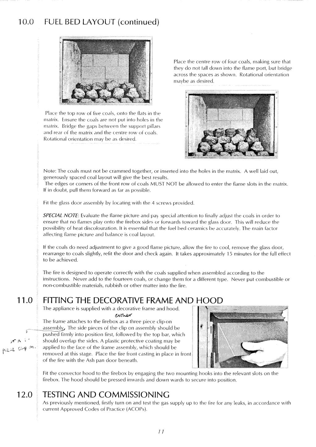
13
14 OPERATING THE APPLIANCE The pilot is visible through the specially added hole in the left hand side of the matrix. Push in and turn the control knob to the SPARK position, and hold there for a few seconds. Continue turning anti-clockwise through the spark click to the PILOT light position, ensuring the pilot has lit. If not, return the knob clockwise and repeat. When the pilot lights after the spark, keep the knob depressed for approximately ten seconds. Now release the knob and the pilot should stay alight. If the pilot is extinguished during use of the fire, you MUST wait ten minutes before repeating the ignition procedure. To achieve the HIGH setting, push the control knob in slightly and continue tuning anti-clockwise to the high position. The main burner should light after a few seconds. To decrease the setting to LOW, turn the control knob clockwise to the low setting. To turn to the PILOT position from the HIGH or LOW positions, press the control knob in slightly, and return to the pilot position and release. To turn the fire OFF, keep the knob pressed in, return to the off position and release. If the fire is switched off during use, ALWAYS wait 3 minutes for the fire to cool safely before attempting to relight. This ensures the safest condition for re-ignition. SPARK FAILURE The gap between the spark electrode and the pilot should be 3-5mm to produce a good spark. There should be no need to adjust this. If under any circumstances the piezo electric spark fails, the pilot cannot be lit manually. SETTING PRESSURE Remove the screw from the pressure test point, situated on the main burner supply pipe just underneath the front of the burner box area and attach a U gauge. Light the fire on the HIGH setting. The setting pressure should be in accordance with the figures stated in the data section of these instructions. The fire is factory set to achieve these pressures and any significant variation could indicate a supply problem.if the pressure is too high, the gas supply meter may be set incorrectly. This should be checked with the fire running and if necessary reset by the gas supplier. If the setting pressure is too low, then check the meter governor pressure with the appliance running. If this is less than approximately 21mbar it will need to be reset by the gas supplier. If the setting pressure is too low, but the meter pressure is acceptable, then a problem in the supply pipework is to be suspected. This will be dirt and debris, kinked or inadequate size pipes, restriction in a fitting, shut off elbow not fully open or solder flashing across a joint. BRIEFING THE CUSTOMER All instructions must be handed to the user for safekeeping. Show the customer how to light and control the fire. After commissioning the appliance, the customer should be instructed on the safe use of the appliance and the need for regular servicing. Frequency of service depends on usage, but MUST be carried out at least once annually. Advise that cleaning of the fire maybe achieved when the fire is cold using a damp cloth and mild detergent on most surfaces. Advise that the fire will emit a "newness" smell for a time after initial commissioning and that extra ventilation may be needed during this time.
15 BRIEFING THE CUSTOMER (continued) Explain that the fire does not use air from the room but ducts fresh air for combustion and exhaust gasses out through the special flue system. The terminal of the flue system must not be allowed to have vegetation growing on or near and must also be kept well clear of any new buildings, sheds, conservatories etc that may be built nearby. Any shielding or damage to the terminal or flue can cause severe damage to the fire and introduce a safety risk to the customer. Recommend that a guard be used for the protection of the young, pets, the elderly and the infirm SERVICING Isolate the fire from the gas supply. Ensure that the fire is fully cold before attempting service. A suggested procedure for servicing is detailed below. 1. Lay out the dust sheet and tools. 2. Remove the hood and front fret. 3. Remove the glass door assembly (4 screws) and clean carefully 4. Carefully remove the ceramic components. 5. Remove the screws that retain the data/control plate. (2 screws) 6. Remove front panel from firebox taking care not to damage sealing gasket. 7. Remove the 2 screws securing burner tray assembly into inner firebox and nuts on gasket plate around gas pipe and undo gas pipe connection under burner box area. Lift away burner tray assembly (tray and gas pipe). 8. Clean the injector, pilot assembly and the burner tube. Do not attempt to remove the pilot injector as this can cause damage. 9. Re-assemble and re-fit the parts including the front panel - making sure that gasket is in good condition. 10. Turn on the gas supply and leak test. Check pilot and burner for good ignition 11. Refit the ceramics, paying attention to the final layout as per installation section. 12. Refit the glass door assembly, ensuring a good seal. 13. Refit the hood. 14. Check the flue terminal for siting and clearance from vegetation etc 15. Light the fire and test setting pressures. 16. Check safe operation of the appliance. For specific servicing instructions, see relevant sections. CLEANING THE COALS Remove the fire front casting and place to one side. Remove the hood. Remove the glass door assembly. Remove the ceramic components. Gently clean in the open air. Be careful not to create dust from the coals. Where necessary replace damaged components with genuine spares. Seal scrap ceramic components in plastic bags and dispose at proper refuse sites as directed. If using a vacuum cleaner, a HEPA filtering system is recommended. Re-fit the coals by referring to the relevant section of these instructions. Refit the glass door assembly ensuring a good seal. Refit the hood. DISMANTLING AND SERVICING THE BURNER TRAY Firstly, remove the hood and front fret, the glass panel, coals and ceramics, data/control plate, burner box front panel, and disconnect the gas connection underneath the burner box area. Remove the burner tray itself by removing the securing screws, releasing the seal around the incoming main burner pipe and lifting away. The 2 screws securing the gas valve bracket should now be removed. The gas connections to the gas valve can now be released and the valve brought forward to remove the thermocouple connection at the rear. Remove the pilot and main burner pipes and blow through to dislodge any debris. Remove the injector and blow through to make sure it is entirely clear. When replacing the injector elbow, ensure that it aligned accurately with the centre of the mixer tube entering the burner and not at an angle. Always make sure that the nut securing the injector elbow is tight. Clean the exterior of the pilot assembly with a soft brush and blow through the flame ports on the pilot head. Check the aeration holes are free from lint or dirt. The pilot assembly can be removed if required by disconnecting the electrode HT lead, gas pipe and unscrewing the mounting screws and lifting away. The pilot assembly is a non-serviceable item and should not be taken apart. Aeration holes must be absolutely clear internally for proper operation. NEVER MODIFY OR BEND THE THERMOCOUPLE TO MAKE THE PILOT STAY ALIGHT.
16 DISMANTLING AND SERVICING THE BURNER TRAY (continued) If the pilot will not stay lit there is a problem with dirt, the gas supply to it, the flue connection or termination, or the thermocouple needs replacement. Modifications are dangerous and can have a serious unseen effect on safety. The integral gas valve pilot filter can be removed and cleaned as follows. Remove the control knob by pulling it forwards, then remove the largest of the three screws on the face of the valve. Slide the filter out and clean away any debris that may have accumulated. The filter element should also be blown clean. This component should not require replacement, however if signs of deterioration are evident then a genuine spare must be used. If a large amount of debris is present in the filter then the pipework and control should be thoroughly cleaned before re-assembly. Re-assembly is the reverse of removal. REMOVING THE FIREBOX Remove all loose parts such as brass frame, hood and fret. Remove the glass panel and ceramics from the firebox. Isolate and disconnect the gas supply at the gas valve. Remove the firebox to cavity box fixings and any seal around the flue pipe where it passes through the outside wall. The firebox should now be free to be lifted out. Refit the firebox as described in the fitting section of these instructions. PILOT ASSEMBLY Remove the hood, glass panel, ceramics and burner tray as described in the section dealing with the burner tray and gas assembly. The pilot can now be accessed easily for cleaning or removal. If removing, take care not to damage the gasket. Clean the pilot assembly with a soft brush and blow through. Check the aeration holes are free of any dirt or lint. Clean thoroughly internally, the connection can be removed from the base of the pilot unit using two spanners to make cleaning easier. Do not damage or try to remove the pilot injector. NEVER MODIFY OR BEND THE THERMOCOUPLE TO MAKE THE PILOT STAY ALIGHT. If the pilot will not stay lit there is a problem with dirt, the gas supply, flue termination or connection, or the thermocouple needs replacement. Modifications are dangerous and can have a serious unseen effect on safety. The unit is factory set and the only check necessary is to ensure the spark gap is correct and that no damage has occurred to the unit. TESTING FOR FIREBOX LEAKAGE The firebox is tested in production for soundness to the required standard. New appliances should present no problem in this regard, however appliances that are several years old or have been extensively dismantled should be checked for soundness. The firebox can be field tested for soundness or leakage by two main methods. A. SMOKE TESTING. The firebox is heated by lighting for a few minutes to provide a flow through the firebox and flue. The burner is then shut off and the firebox is opened and a smoke pellet introduced or smoke is introduced to the air intake (outer) duct of the flue terminal. Large quantities of smoke emerging from the appliance at joints or gasket faces indicate where major leaks may be occurring. It is important to note that the appliance can never be expected to be 100% smoke tight and small quantities of smoke may be seen in corners of joints and gasket faces etc without affecting safety when the fire is actually in operation. B. GAS SAMPLING. This is done with a CO/CO2 analyser with the fire running. Samples of the con vection air and room air are taken before and after the fire is lit to ascertain if the fire is leaking com bustion products at significant levels. It is important to note that sampling with a probe right next to a joint or gasket face is not a reliable test, as the action of the analyser sucking and locally high concen trations of gas will significantly affect the reliability of readings. The important point to note is whether there is a significant increase in ambient CO/CO2 in the room air after 15 to 30 minutes operating. A small or negligible increase indicates insignificant leakage rates. A significant increase warrants further inspection and testing with smoke as described above to isolate and eliminate leaks.
17 TROUBLESHOOTING GUIDE Fire sparks but pilot does not light No gas to fire, check isolators are open. Pipework blockage, clean out. Air not fully purged, re purge supply or wait longer. Spark earthing to metal work, reset gap correctly. Blocked pilot, clean out internally. Pilot light but then goes out Fire does not spark at pilot Fire runs for a time and then cuts off Pilot flame shrinks when fire is on high Fire smells when first lit Severe restriction in gas supply: clear obstruction. Faulty thermocouple, replace pilot unit. Blocked pilot, clean out. Hold control knob in for longer. Check control knob does not foul data plate. Flue disconnected or connection damaged, partly or fully blocked, terminal obscured or damaged. NEVER MODIFY OR BEND THE THERMOCOUPLE TO MAKE THE PILOT STAY ALIGHT. If the pilot will not stay lit there is a problem with dirt, the gas supply, flue termination or connection, or the thermocouple needs replacement. Modifications are dangerous and can have a serious unseen effect on safety. Fire does not spark at pilot HT lead detached, refit. Spark gap too large or small, reset correctly. Faulty piezo unit, replace. Debris shorting out electrode, clean. Spark shorting to metalwork under tray, realign HT lead. Fire runs for a time and then cuts off Loose or faulty thermocouple, rectify. Blocked pilot, clean out. Dirt or lint in pilot aeration hole, clean thoroughly internally. Flue disconnected or connection damaged, partly or fully blocked, terminal obscured or damaged. NEVER MODIFY OR BEND THE THERMOCOUPLE TO MAKE THE PILOT STAY ALIGHT. If the pilot will not stay lit there is a problem with dirt, the gas supply, flue termination or connection, or the thermocouple needs replacement. Modifications are dangerous and can have a serious unseen effect on safety. Poor gas flow to fire, check pressure with fire on high. If pressure is low, remove any restriction in pipework or valve. Check all isolators are adequately sized and fully open. Check meter pressure is adequate. Flue disconnected or connection damaged, partly or fully blocked, terminal obscured or damaged. NEVER MODIFY OR BEND THE THERMOCOUPLE TO MAKE THE PILOT STAY ALIGHT. If the pilot will not stay lit there is a problem with dirt, the gas supply, flue termination or connection, or the thermocouple needs replacement. Modifications are dangerous and can have a serious unseen effect on safety. Newness smell from brand new appliance. Leakage occurring. Carry out leakage test and rectify any problems. Low temperature sealants or combustible materials used in incorrect positions.
18 USER INSTRUCTIONS Section Contents Page No. Important Notes Firefront Clearance to Combustibles Ventilation Operating Instructions Cleaning Coals and Ceramics Servicing List of Spare Parts 3 IMPORTANT NOTES The installation and Servicing of this fire MUST only be carried out by a competent person (such as a CORGI registered fitter) in accordance with the Gas Safety (Installation and Use) Regulations 1998, the relevant British Standards, Codes of Practice, the Building Regulations and the manufacturer's instructions. Failure to comply with the above recommendations could lead to prosecution and invalidate the appliance warranty. Please ensure you are handed all of the manufacturers documents on completion of the installation. This will include these instructions. Always keep a note of the installer's name and address, the original purchase receipt and the date of installation for future reference. The fire and flue should be serviced regularly to ensure continued safe operation. See the servicing section for further reference. Parts of this appliance become naturally hot during use. It is recommended that a suitable fire guard conforming to BS 6778 or BS 6539 is used, especially where young children, pets, the elderly or infirm are concerned. The manufacturer of this appliance considers all surfaces as working surfaces with the exception of the control knob, control panel and ash pan cover. Combustible items, such as flooring and furniture and soft wall coverings (such as blown vinyl or embossed paper), low temperature surrounds etc may discolour if fitted too close to the fire. See relevant section for further details on clearances to combustibles. No combustible materials or flooring should protrude onto the hearth. DO NOT burn any foreign material on this fire, the coals must be of the correct type and laid out in accordance with the relevant section of the these instructions. Failure to do so may create a hazard or lead to sooting. Under no circumstances shall the appliance be used if the glass front door or panel has been, removed or is open. The integral appliance flue should be checked by the installer upon servicing to ensure there are no defects or obstructions that may prevent the satisfactory flow of combustion products. This appliance is only suitable for the gas type for which it is supplied. FIREFRONT This fire is supplied with a particular style of fire front. Use of the fire front will ensure an adequate airflow under the firebox for the correct efficiency and control temperatures of this appliance. Whilst other fronts can be used, compliance with temperature standards cannot be guaranteed when another style of front is used.
19 CLEARANCES TO COMBUSTIBLES A non-combustible shelf may be fitted to within 100mm of the top edge of the fire frame. However the items placed on it must also be able to withstand high temperatures. A combustible shelf may be fixed to the wall above the fire, providing that is complies with the dimensions given below. Maximum depth of shelf Minimum distance from hearth to underside of shelf 180mm 850mm Combustible materials, such as wood, may be fitted to within 100mm (4in) of either side of the frame of the appliance, providing the forward projection does not exceed 100mm (4in). Any combustible side walls must be at least 500mm to the side of the radiant heat source. As with all heating appliances, any decorations, soft furnishings and wall coverings (i.e. flock, blown vinyl and embossed paper) positioned too close to the appliance may discolour or scorch. VENTILATION No purpose provided ventilation is required for this appliance because it is room sealed. The requirements of other open flued appliances operating in the same room or space must be taken into consideration when assessing ventilation. The combustion air supply for this appliance is ducted from the outside air by an integral flue system. The terminal of this flue system must always be kept clear of vegetation, new buildings, conservatories, extensions, sheds or other potential obstructions and able to perform its function correctly. A supply of fresh air into the room is advisable to maintain temperatures within limits. For Republic of Ireland, see relevant rules in force. OPERATING INSTRUCTIONS The pilot is visible through the small hole in the left hand side of the matrix base. Push in and turn the control knob to the SPARK position, and hold there for a few seconds. Continue turning anti-clockwise through the spark click to the PILOT light position, ensuring the pilot has lit. If not, return the knob clockwise and repeat. When the pilot lights after the spark, keep the knob depressed for approximately ten seconds. Now release the knob and the pilot should stay alight. If the pilot is extinguished during use of the fire, you MUST wait three minutes before repeating the ignition procedure. To achieve the HIGH setting, push the control knob in slightly and continue tuning anti-clockwise to the high position. The main burner should light after a few seconds. To decrease the setting to LOW, turn the control knob clockwise to the low setting. To turn to the PILOT position from the HIGH or LOW positions, press the control knob in slightly, and return to the pilot position and release. To turn the fire OFF, keep the knob pressed in, return to the off position and release. If the fire is switched off during use, ALWAYS wait 3 minutes for the fire to cool safely before attempting to relight. This ensures the safest condition for re-ignition. To turn the fire OFF, keep the knob pressed in, return to the off position and release. CLEANING Before carrying out any of the following operations, ensure that the fire is OFF and completely cold. Debris that may form on the fire bed should be periodically removed by a competent person. Large deposits could indicate flue problems or incorrect coal placement. This should be repaired by a competent person and the fire serviced before further use. To gain access to the fire bed, remove the hood and glass door assembly.
20 The hood should be lifted and pulled outwards to disengage, then remove the door by removing the four screws and lifting away. The glass can be cleaned with a suitable glass cleaner. FIREFRONT - Any dust accumulating in the fire front may be removed using a vacuum cleaner or dry cloth. Heavy stains may be removed by using a damp cloth and mild household detergent. Brass parts of the fire front may be cleaned using a suitable brass cleaner. Replace the front centrally against the fire after cleaning. PAINTED AREAS - These can be cleaned using a dry cloth. COALS AND CERAMICS See the relevant section in the Installation Guide of these instructions. Clean coals gently in open air. Do not create dust from the coals. If using a vacuum cleaner, a HEPA filter system is recommended. SERVICING The fire and flue should be checked on an annual basis to it is working safely and that there is no excessive build up of soot. The frequency of service will depend on usage, but MUST be carried out at least once annually. Servicing must be carried out by a competent person, such as a CORGI registered installer. Cleaning of the coals may be carried out by following the instructions given in the Installation section. The Installation instructions carry full servicing details for the use of the installer. LIST OF SPARE PARTS PART NO. ITEM?????????? Pack of 14 coals?????????? Ceramic combustion matrix?????????? Ceramic side cheeks?????????? Ceramic brick panel Please enquire Decorative frame Please enquire Decorative fret?????????? Glass door assembly Please enquire Hood?????????? Pilot assembly?????????? Gas valve?????????? Burner tray?????????? Pilot Gasket?????????? Gas pipe gasket?????????? Front panel gasket????????? Outer tray gasket
INSTALLATION & USER INSTRUCTIONS INSET DECORATIVE GAS FIRE
 INSTALLATION & USER INSTRUCTIONS INSET DECORATIVE GAS FIRE MODELS COVERED BY THESE INSTRUCTIONS HANNINGTON BRASS F500310 HANNINGTON BLACK F500311 Focal Point Fires plc. Christchurch, Dorset BH23 2BT Tel:
AFINA FLUELESS GAS STOVE INSTALLATION AND USER INSTRUCTIONS
 AFINA FLUELESS GAS STOVE INSTALLATION AND USER INSTRUCTIONS All instructions must be handed to user for safekeeping Revision A - 08/05 Country(s) of destination - GB/IE CK Fires Ltd. 1 Stour House, Clifford
Model Apex Falcon, Titan & Zenit
 Model Apex Falcon, Titan & Zenit Installation and User Instructions All instructions must be handed to user for safekeeping This is not a DIY product and must be installed by a Gas Safe registered installer
installation and user instructions
 installation and user instructions All instructions must be handed to user for safekeeping Revision B - 08/11 Country(s) of destination - GB/IE eko 5510 eko 5520 eko 5530 high efficiency flueless gas fire
L23 BLACK P23 CONTEMPORARY GLASS
 L23 BLACK P23 CONTEMPORARY GLASS FLUELESS GAS FIRE INSTALLATION AND USER INSTRUCTIONS All instructions must be handed to user for safekeeping Revision A - 03/08 Country(s) of destination - GB/IE Focal
installation and user instructions
 installation and user instructions All instructions must be handed to user for safekeeping Revision A - 06/09 Country(s) of destination - GB/IE eko 00 fuel effect gas fire INSTALLATION INSTRUCTIONS Preliminary
NIGMA. Fuel Effect Gas Fire INSTALLATION, SERVICING AND USER INSTRUCTIONS. All instructions must be handed to the user for safekeeping
 Σ NIGMA Fuel Effect Gas Fire INSTALLATION, SERVICING AND USER INSTRUCTIONS All instructions must be handed to the user for safekeeping Revision A 09/03 Country(s) of destination: GB, IE Focal Point Fires
installation and user instructions
 installation and user instructions All instructions must be handed to user for safekeeping Revision A - 08/09 Country(s) of destination - GB/IE eko 4010 eko 400 high efficiency fuel effect gas fire Eko
INSTALLATION & USER INSTRUCTIONS
 INSTALLATION & USER INSTRUCTIONS INSET FLUELESS GAS FIRE Focal Point Fires plc. Christchurch, Dorset BH23 2BT Tel: 01202 499330 Fax: 01202 499326 www.focalpointfires.co.uk e : sales@focalpointfires.co.uk
ARIES AURA BLENHEIM STYLE
 ARIES AURA BLENHEIM STYLE FULL DEPTH GAS FIRE INSTALLATION AND USER INSTRUCTIONS All instructions must be handed to user for safekeeping Revision A - 05/05 Country(s) of destination - GB/IE Focal Point
INSTALLATION & USER INSTRUCTIONS
 INSTALLATION & USER INSTRUCTIONS STONE EFFECT DECORATIVE GAS FIRE MODELS COVERED BY THESE INSTRUCTIONS POLARIS GB IE Focal Point Fires plc. Christchurch, Dorset BH23 2BT Tel: 01202 499330 Fax: 01202 499326
COAL EFFECT BALANCED FLUE GAS FIRE
 Raglan COAL EFFECT BALANCED FLUE GAS FIRE Installation and Maintenance Instructions Hand these instructions to the user Model No. KBFC**MN for use on Natural Gas (G20) at a supply pressure of 20 mbar in
PLATINUM FIRES. Revision A - 10/05 Country(s) of destination - GB/IE
 of destination - GB/IE") PLATINUM FIRES ADEN ALITA ALVA FLUELESS GAS FIRE INSTALLATION AND USER INSTRUCTIONS All instructions must be handed to user for safekeeping Revision A - 10/05 Country(s) of destination - GB/IE Platinum
PLATINUM FIRES ADEN ALITA ALVA FLUELESS GAS FIRE INSTALLATION AND USER INSTRUCTIONS All instructions must be handed to user for safekeeping Revision A - 10/05 Country(s) of destination - GB/IE Platinum
INSTALLATION, USERS AND SERVICING INSTRUCTIONS
 INSTALLATION, USERS AND SERVICING INSTRUCTIONS SLIMLINE (FAN FLUE) HOTBOX Inset Decorative coal or pebble effect Gas Fire For use with Natural Gas (G20) @ 20mbar or Butane (G30) @ 28mbar or Propane (G31)
installation and user instructions
 installation and user instructions All instructions must be handed to user for safekeeping Revision A - 06/09 Country(s) of destination - GB/IE eko 3030 eko 3035 eko 3040 eko 3050 eko 3060 eko 3065 fuel
installation and user instructions
 installation and user instructions All instructions must be handed to user for safekeeping Revision A - 06/09 Country(s) of destination - GB/IE eko 010 - eko 020 fuel effect gas fire manual - remote control
PLASMA CAPELLA PLATINUM
 PLASMA CAPELLA PLATINUM FLUELESS GAS FIRE INSTALLATION AND USER INSTRUCTIONS All instructions must be handed to user for safekeeping Revision C - 08/08 Country(s) of destination - GB/IE Focal Point Fires
SLIMLINE RADIANT GAS FIRE
 SLIMLINE RADIANT GAS FIRE FOR USE WITH CHLOE - JULIET - NEW WAVE - HEAT WAVE ANNABELLE - ZARA - CARMEN - CARMEN HIW INSTALLATION AND USER INSTRUCTIONS All instructions must be handed to user for safekeeping
Orchestra COAL EFFECT BALANCED FLUE GAS FIRE
 Orchestra COAL EFFECT BALANCED FLUE GAS FIRE Installation and Maintenance Instructions Hand these instructions to the user Model No s FBFN76G & FBFN98G are for use on Natural Gas (G20) at a supply pressure
ULTIMATE INSET LIVE FUEL EFFECT GAS FIRE MODEL 417 OWNER GUIDE
 ULTIMATE INSET LIVE FUEL EFFECT GAS FIRE MODEL 417 OWNER GUIDE THE NATURAL GAS MODEL IS FOR G20 AT A SUPPLY PRESSURE OF 20mbar THE PROPANE GAS MODEL IS FOR G31 AT A SUPPLY PRESSURE OF 37mbar THESE APPLIANCES
INSTALLATION & USER INSTRUCTIONS
 INSTALLATION & USER INSTRUCTIONS INSET DECORATIVE GAS FIRE MODELS COVERED BY THESE INSTRUCTIONS eko 2050 Christchurch, Dorset BH23 2BT Tel: 01202 588 638 Fax: 01202 499 639 www.ekofires.co.uk e-mail: sales@ekofires.co.uk
Excelsior. Fuel Effect Gas Fire INSTALLATION, SERVICING AND USER INSTRUCTIONS. All instructions must be handed to the user for safekeeping
 Excelsior Fuel Effect Gas Fire Fanflue INSTALLATION, SERVICING AND USER INSTRUCTIONS All instructions must be handed to the user for safekeeping Revision A 04/02 Country(s) of destination: GB, IE Focal
INSTALLATION & USER INSTRUCTIONS FULL DEPTH RADIANT/CONVECTOR INSET GAS FIRE
 INSTALLATION & USER INSTRUCTIONS FULL DEPTH RADIANT/CONVECTOR INSET GAS FIRE MODELS COVERED BY THESE INSTRUCTIONS GB IE ELYSEE RADIANT F500007 Focal Point Fires plc. Christchurch, Dorset BH23 2BT Tel:
INSTALLATION & USER INSTRUCTIONS WALL MOUNTED HIGH EFFICIENCY GAS FIRE
 INSTALLATION & USER INSTRUCTIONS WALL MOUNTED HIGH EFFICIENCY GAS FIRE MODELS COVERED BY THESE INSTRUCTIONS Focal Point Fires plc. Christchurch, Dorset BH23 2BT Tel: 01202 499330 Fax: 01202 499326 www.focalpointfires.co.uk
INSTALLATION & USER INSTRUCTIONS
 INSTALLATION & USER INSTRUCTIONS FULL DEPTH RADIANT & CONVECTOR GAS FIRES Focal Point Fires plc. Christchurch, Dorset BH23 2BT Tel: 01202 499330 Fax: 01202 499326 www.focalpointfires.co.uk e : sales@focalpointfires.co.uk
installation and user instructions
 installation and user instructions All instructions must be handed to user for safekeeping Revision A - 06/09 Country(s) of destination - GB/IE eko 3021 eko 3031 fan-flue fuel effect gas fire INSTALLATION
Kalahari DECORATIVE FUEL EFFECT GAS FIRE
 Kalahari DECORATIVE FUEL EFFECT GAS FIRE User Instructions These instructions should be read by the user before operating the appliance and retained for future reference Model No. KRDC00MN & KRDC00SN are
BALLADE BALANCED FLUE CONVECTOR FIRE
 BALLADE BALANCED FLUE CONVECTOR FIRE MODEL No VBFC 16NG GAS COUNCIL NO. 32-234-14 THIS IS NOT A DO IT YOURSELF PRODUCT THIS APPLIANCE MUST BE INSTALLED BY A CORGI REGISTERED PERSON INSTALLATION, SERVICING
INSTALLATION & USER INSTRUCTIONS
 INSTALLATION & USER INSTRUCTIONS HIGH EFFICIENCY GAS FIRE MODELS COVERED BY THESE INSTRUCTIONS BLENHEIM HE GAS FIRE HORIZON HE GAS FIRE LULWORTH HE GAS FIRE Focal Point Fires plc. Christchurch, Dorset
OWNER S GUIDE ETERNITY. MODEL 540C (GC No ) INSET BALANCED FLUE GAS FIRE
 INSET BALANCED FLUE GAS FIRE") 600B637/02 ETERNITY MODEL 540C (GC No. 32-032-19) INSET BALANCED FLUE GAS FIRE THIS APPLIANCE IS FOR USE WITH NATURAL GAS (G20) THIS APPLIANCE IS FOR USE IN THE UNITED KINGDOM (GB) AND THE REPUBLIC OF
600B637/02 ETERNITY MODEL 540C (GC No. 32-032-19) INSET BALANCED FLUE GAS FIRE THIS APPLIANCE IS FOR USE WITH NATURAL GAS (G20) THIS APPLIANCE IS FOR USE IN THE UNITED KINGDOM (GB) AND THE REPUBLIC OF
installation and user instructions
 installation and user instructions All instructions must be handed to user for safekeeping Revision A - 06/09 Country(s) of destination - GB/IE eko 5010 eko 5020 eko 5030 eko 5040 fuel effect gas fire
STONE CONTEMPORARY GLASS
 STONE LIMESTONE - GRANITE CONTEMPORARY GLASS FLUELESS GAS FIRE INSTALLATION AND USER INSTRUCTIONS All instructions must be handed to user for safekeeping Revision A - 06/08 Country(s) of destination -
MODEL 466 Radiant / Convector Gas Fire Black Beauty
 O W N E R G U I D E MODEL 466 Radiant / Convector Gas Fire Black Beauty This Owner Guide is intended to help you care for your Valor gas fire. Please read carefully before using your gas fire and keep
5traxo INSTALLATION AND SERVICING INSTRUCTIONS MANDATORY REQUIREMENTS INSTALLATION
 5traxo Division of Legge Fabheat Ltd Longfield Road, Sydenham, Leamington Spa CV31 1XB Tel. (0926) 882233 Fax (0926) 450846 Registered in England No. 500091 Universal INSTALLATION AND SERVICING INSTRUCTIONS
INSTALLATION & USERS INSTRUCTIONS. FOR USE WITH NATURAL GAS 20 mbar For use in GB and IE
 1 valentine s buildings Bechers drive Aintree racecourse Business Park L9 5ay CF1 L GAS APPLIANCE INSET CONVENTIONAL FLUED GAS FIRE INSTALLATION & USERS INSTRUCTIONS FOR USE WITH NATURAL GAS G20 @ 20 mbar
BLACK KNIGHT 2 - Classic Collection
 BLACK KNIGHT 2 - Classic Collection Installation & Servicing Instructions (GC No. 32 170 16) IMPORTANT - THIS FIRE DOES NOT NORMALLY REQUIRE ADDITIONAL VENTILATION INTO THE ROOM IN WHICH IT IS INSTALLED
Napoli BF COAL EFFECT BALANCED FLUE GAS FIRE
 Napoli BF COAL EFFECT BALANCED FLUE GAS FIRE Installation, Maintenance & User Instructions Hand these instructions to the user Model No. ABFC**MN2 & ABFC**EN3 are for use on Natural Gas (G20) at a supply
OWNER S GUIDE MODEL BR417 VA
 600B702/06 OWNER S GUIDE MODEL BR417 VA (G.C.32-032-07) Inset Live Fuel Effect Gas Fire with Ultimate Front AS SUPPLIED, THIS APPLIANCE IS FOR USE WITH NATURAL GAS (G20) WHEN CONVERTED USING VALOR CONVERSION
INSTALLATION INSTRUCTIONS COMPACT GAS STOVE MODEL NUMBER 550
 INSTALLATION INSTRUCTIONS COMPACT GAS STOVE MODEL NUMBER 550 Before installation ensure that the local distribution conditions (identification of the type of gas and pressure) and the adjustment of the
MODEL 466 Radiant / Convector Gas Fire Black Beauty
 I N S T A L L E R G U I D E MODEL 466 Radiant / Convector Gas Fire Black Beauty Please keep in a safe place for future reference 600A734/02 Please leave this Installer Guide with the user This appliance
GrateGlow THE ALL NEW CAPITAL COLLECTION. G20 at 20mbar convertible to G31 at 37mbar. For use in GB and le. Users Instructions
 GrateGlow A CARVER GROUP COMPANY --..--... THE GAS CONSUMERS' COUNCIL (GCC) IS AN INDEPENDENT ORGANISATION WHICH PROTECTS THE INTEREST OF GAS USERS. IF YOU NEED ADVICE, YOU WILL FIND THE TELEPHONE NUMBER
CRYSTAL FIRES. Inset Conventional Flue Fire. (BOSTON/MIAMI) Cf1 and MANHATTAN USER INSTALLATION AND SERVICING INSTRUCTIONS
 Cf1 and MANHATTAN USER INSTALLATION AND SERVICING INSTRUCTIONS") CRYSTAL FIRES (BOSTON/MIAMI) Cf1 and MANHATTAN Inset Conventional Flue Fire USER INSTALLATION AND SERVICING INSTRUCTIONS FOR USE WITH NATURAL GAS G20 @ 20 mbar For use in GB and IE CE THESE INSTRUCTIONS
CRYSTAL FIRES (BOSTON/MIAMI) Cf1 and MANHATTAN Inset Conventional Flue Fire USER INSTALLATION AND SERVICING INSTRUCTIONS FOR USE WITH NATURAL GAS G20 @ 20 mbar For use in GB and IE CE THESE INSTRUCTIONS
Dovre 250 Cast Iron Gas Stove
 Dovre 50 Cast Iron Gas Stove NATURAL GAS AND LPG INSTALLATION, SERVICING AND USER INSTRUCTIONS THIS PRODUCT IS FOR USE ONLY IN GREAT BRITAIN AND IRELAND These instructions are to be left with the customer,
(manual control) (ezi-slide control) INSET COAL EFFECT GAS CONVECTOR FIRE V1/100/B INSTALLATION & USER INSTRUCTIONS
 (ezi-slide control) INSET COAL EFFECT GAS CONVECTOR FIRE V1/100/B INSTALLATION & USER INSTRUCTIONS") Model Number: V1/100/A V1/100/B (manual control) (ezi-slide control) INSET COAL EFFECT GAS CONVECTOR FIRE INSTALLATION & USER INSTRUCTIONS GB IE SUITABLE FOR USE ON NATURAL GAS (G20) AT 20mbar SUPPLY PRESSURE
Model Number: V1/100/A V1/100/B (manual control) (ezi-slide control) INSET COAL EFFECT GAS CONVECTOR FIRE INSTALLATION & USER INSTRUCTIONS GB IE SUITABLE FOR USE ON NATURAL GAS (G20) AT 20mbar SUPPLY PRESSURE
INSET LIVE FUEL EFFECT GAS FIRE
 600B741/02 OWNER S GUIDE MODEL BR650 VA (GC No. 32-032-39) INSET LIVE FUEL EFFECT GAS FIRE THIS APPLIANCE IS FOR USE WITH NATURAL GAS (G20) WHEN CONVERTED USING CONVERSION KIT NO.591149 THIS APPLIANCE
INSTALLATION & USER INSTRUCTIONS
 INSTALLATION & USER INSTRUCTIONS MULTIFLUE/INSET GAS FIRE Focal Point Fires plc. Christchurch, Dorset BH23 2BT Tel: 01202 499330 Fax: 01202 499326 www.focalpointfires.co.uk e : sales@focalpointfires.co.uk
Black Beauty Unigas II
 I N S T A L L E R G U I D E MODEL 473 Room Sealed Radiant / Convector Gas Fire Black Beauty Unigas II Please keep in a safe place for future reference 2 600A742/02 Please leave this Installer Guide with
INSTALLATION & USER INSTRUCTIONS
 INSTALLATION & USER INSTRUCTIONS WALL MOUNTED HIGH EFFICIENCY GAS FIRE Christchurch, Dorset BH23 2BT Tel: 01202 588 638 Fax: 01202 499 639 www.ekofires.co.uk e-mail: sales@ekofires.co.uk MODELS COVERED
PARAGON FIRES. PARAGON FOCUS RS 18 Manual Version ROOM SEALED INSET LIVE FUEL EFFECT GAS FIRE OWNER'S MANUAL
 PARAGON FIRES PARAGON FOCUS RS 18 Manual Version ROOM SEALED INSET LIVE FUEL EFFECT GAS FIRE OWNER'S MANUAL Please read these instructions carefully before you start using the appliance Keep this booklet
PARAGON 2000 Plus MANUAL TURBO. Owner's Book
 PARAGON FIRES PARAGON 2000 Plus MANUAL TURBO Owner's Book NATURAL GAS & PROPANE GAS MODELS SURFACE MOUNTED POWER FLUE UNIT Or SUNK IN THE WALL POWER FLUE UNIT INCLUDES USER, INSTALLATION & MAINTENANCE
Baxi Brazilia F5, F5S & F8S
 Baxi Brazilia F5, F5S & F8S Balanced Flue Gas Wall Heaters Comp No. 243469 - Iss 1-6/99 Installation and Servicing Instructions Natural Gas Baxi Brazilia F 5 G.C.No. 35 075 0lA Baxi Brazilia F 5S Grey
OWNER GUIDE. Model 739 OPEN DECORATIVE GAS FIRE. (GC No )
") 5113426/01 OWNER GUIDE Model 739 OPEN DECORATIVE GAS FIRE (GC No. 32-032-54) THIS APPLIANCE IS FOR USE WITH NATURAL GAS (G20). WHEN CONVERTED USING CONVERSION KIT NO. 0595211 THIS APPLIANCE IS FOR USE
5113426/01 OWNER GUIDE Model 739 OPEN DECORATIVE GAS FIRE (GC No. 32-032-54) THIS APPLIANCE IS FOR USE WITH NATURAL GAS (G20). WHEN CONVERTED USING CONVERSION KIT NO. 0595211 THIS APPLIANCE IS FOR USE
INSTALLATION & USER INSTRUCTIONS
 INSTALLATION & USER INSTRUCTIONS MULTIFLUE/INSET GAS FIRE Pure Glow Limited Stour Vale Road Lye, Stourbridge West Midlands DY9 8PP t: 01384 893060 f: 01384 897728 www.pureglowltd.co.uk email: info@pureglowltd.co.uk
Installation & Service Instructions
 Part No. 966/9350/1 02 Potterton Housewarmer Illusion ASD - G.C. NO. 37 590 16 966 Inset DGF with ILLUSION FACIA Potterton Housewarmer Stratton ASD - G.C. NO. 37 590 17 966 Inset DGF with STRATTON FACIA
MUSE MODEL : P23 WALL MOUNTED FLUELESS GAS FIRE
 MUSE MODEL : P23 WALL MOUNTED FLUELESS GAS FIRE INSTALLATION INSTRUCTIONS It is the LAW that all gas appliances and fittings are installed by a competent person (such as a CORGI registered fitter) and
PARAGON FIRES. PARAGON FOCUS RS PLUS Slide Control ROOM SEALED INSET LIVE FUEL EFFECT GAS FIRE OWNER'S MANUAL
 PARAGON FIRES PARAGON FOCUS RS PLUS Slide Control ROOM SEALED INSET LIVE FUEL EFFECT GAS FIRE OWNER'S MANUAL Please read these instructions carefully before you start using the appliance Keep this booklet
INSTALLATION & USER INSTRUCTIONS
 INSTALLATION & USER INSTRUCTIONS Focal Point Fires plc. Christchurch, Dorset BH23 2BT Tel: 01202 499330 Fax: 01202 499326 www.focalpointfires.co.uk e : sales@focalpointfires.co.uk WALL INSET GAS FIRES
Limours. Balanced Flue Room Heater MODEL NUMBER : KBFP00RN INSTALLATION, USER AND SERVICING INSTRUCTIONS THESE INSTRUCTIONS MUST REMAIN WITH THE USER
 Limours Balanced Flue Room Heater MODEL NUMBER : KBFP00RN INSTALLATION, USER AND SERVICING INSTRUCTIONS THESE INSTRUCTIONS MUST REMAIN WITH THE USER This appliance is suitable for use on Natural Gas (G20)
NOVO HIGH EFFICIENCY GAS FIRE MODELS : P23G, L23G. All instructions must be handed to user for safekeeping
 NOVO HIGH EFFICIENCY GAS FIRE MODELS : P23G, L23G All instructions must be handed to user for safekeeping Revision E - 01/13 Country(s) of destination - GB/IE Pure Glow Limited Stourvale Road Lye Stourbridge
INSTALLATION & USER INSTRUCTIONS
 INSTALLATION & USER INSTRUCTIONS WALL MOUNTED HIGH EFFICIENCY GAS FIRE MODELS COVERED BY THESE INSTRUCTIONS 5090 GAS FIRE GB IE Christchurch, Dorset BH23 2BT Tel: 01202 588 638 Fax: 01202 499 639 www.ekofires.co.uk
RADIANT / CONVECTOR GAS FIRE MODEL 426 (GC ) INSTALLATION & SERVICING INSTRUCTIONS INSTALLER: Please leave these instructions with the owner
 INSTALLATION & SERVICING INSTRUCTIONS INSTALLER: Please leave these instructions with the owner") THIS APPLIANCE IS FOR USE WITH NATURAL GAS (G20) AT A SUPPLY PRESSURE OF 20mbar (8in w.g.) THIS APPLIANCE IS FOR USE IN THE UNITED KINGDOM (GB) AND THE REPUBLIC OF IRELAND (IE) RADIANT / CONVECTOR GAS
THIS APPLIANCE IS FOR USE WITH NATURAL GAS (G20) AT A SUPPLY PRESSURE OF 20mbar (8in w.g.) THIS APPLIANCE IS FOR USE IN THE UNITED KINGDOM (GB) AND THE REPUBLIC OF IRELAND (IE) RADIANT / CONVECTOR GAS
Classic DECORATIVE FUEL EFFECT GAS FIRE. Installation, Maintenance & User Instructions
 Classic DECORATIVE FUEL EFFECT GAS FIRE Installation, Maintenance & User Instructions Hand these instructions to the user Model No s CSRC**MN is only for use on Natural Gas (G20) at a supply pressure of
Plus Model BR645 VA (G.C )
") 600B656/05 Plus Model BR645 VA (G.C. 32-032-34) As supplied, this appliance is for use with natural gas (G20) When converted using conversion kit no. 591149 this appliance is for use with propane gas (G31)
600B656/05 Plus Model BR645 VA (G.C. 32-032-34) As supplied, this appliance is for use with natural gas (G20) When converted using conversion kit no. 591149 this appliance is for use with propane gas (G31)
INSTALLATION & USER INSTRUCTIONS
 INSTALLATION & USER INSTRUCTIONS HIGH EFFICIENCY GAS STOVE MODELS COVERED BY THESE INSTRUCTIONS LEIRVIK FLUELESS STOVE DALVIK FLUELESS STOVE Focal Point Fires plc. Christchurch, Dorset BH23 2BT Tel: 01202
Emberglow COAL EFFECT BALANCED FLUE GAS FIRE
 Emberglow COAL EFFECT BALANCED FLUE GAS FIRE User Instructions These instructions should be read by the user before operating the appliance and retained for future reference Model No. FEBC00MN is only
Sonnet Plus Anthem Genesis Soraya
 5108617/01 OWNER GUIDE Sonnet Plus Anthem Genesis Soraya Model 746 (GC No. 32-032-57) INSET LIVE FUEL EFFECT GAS FIRE THIS APPLIANCE IS FOR USE WITH NATURAL GAS (G20) WHEN CONVERTED USING CONVERSION KIT
EMBERGLOW CLASSIC RADIANT CONVECTOR GAS FIRE. Installation and Maintenance Instructions
 , EMBERGLOW CLASSIC RADIANT CONVECTOR GAS FIRE Installation and Maintenance Instructions Hand these instructions to the user Model No. FEMC00MN is for use on Natural Gas (G20) at a supply pressure of 20
Kalahari RC & Camber RC
 Kalahari RC & Camber RC DECORATIVE FUEL EFFECT GAS FIRE User Instructions These instructions should be read by the user before operating the appliance and retained for future reference Model No s KRDC**RN
INSTALLER S GUIDE. MODEL 639 Open Decorative Gas Fire
 3002369/03 INSTALLER S GUIDE MODEL 639 Open Decorative Gas Fire (G.C No. 32-032-47) THIS APPLIANCE IS FOR USE WITH NATURAL GAS (G20) WHEN CONVERTED USING CONVERSION KIT NO. 0591301 THIS APPLIANCE IS FOR
Sonnet Plus Anthem Genesis Soraya
 5110524/01 OWNER GUIDE Sonnet Plus Anthem Genesis Soraya Model 747 (GC No. 32-032-51) INSET LIVE FUEL EFFECT GAS FIRE THIS APPLIANCE IS FOR USE WITH NATURAL GAS (G20) WHEN CONVERTED USING CONVERSION KIT
OWNER GUIDE. Anthem, Bolero, Camden, Minima, Victorian or Westminster fascia
 5114465/01 OWNER GUIDE Model 741 INSET LIVE FUEL EFFECT GAS FIRE Fitted with Anthem, Bolero, Camden, Minima, Victorian or Westminster fascia (GC No. 32-032-56) THIS APPLIANCE IS FOR USE WITH NATURAL GAS
Corda Powerflue FUEL EFFECT POWERFLUE GAS FIRES
 Corda Powerflue FUEL EFFECT POWERFLUE GAS FIRES Installation, Maintenance & User Instructions Hand these instructions to the user Model No s GVNC**MN & GVNP**MN are for use on Natural Gas (G20) at a supply
OWNER GUIDE. Model 750. INSET LIVE FUEL EFFECT GAS FIRE Fitted with Harmony, Avignon or Style fascia. (GC No )
") 5112499/01 OWNER GUIDE Model 750 INSET LIVE FUEL EFFECT GAS FIRE Fitted with Harmony, Avignon or Style fascia (GC No. 32-032-58) THIS APPLIANCE IS FOR USE WITH NATURAL GAS (G20) WHEN CONVERTED USING CONVERSION
5112499/01 OWNER GUIDE Model 750 INSET LIVE FUEL EFFECT GAS FIRE Fitted with Harmony, Avignon or Style fascia (GC No. 32-032-58) THIS APPLIANCE IS FOR USE WITH NATURAL GAS (G20) WHEN CONVERTED USING CONVERSION
Model BR660VA Heat Engine
 5112253/01 Model BR660VA Heat Engine POWER FLUE INSET GAS FIRE (GC No. 32-032-44) THIS APPLIANCE IS FOR USE WITH NATURAL GAS (G20). WHEN CONVERTED USING CONVERSION KIT NO. 0591149 THIS APPLIANCE IS FOR
Model 341 Black Beauty Slimline
 600B690/13 OWNER GUIDE Model 341 Black Beauty Slimline LIVE FUEL EFFECT GAS FIRE (GC No. 32-032-30) We trust that this guide gives sufficient details to enable this appliance to be operated and maintained
ATHENA R.S. LPG. Room Sealed Inset Live Fuel Effect Gas Fire. PRODUCT No. A99011 G.C. No Installation and Servicing Instructions
 ATHENA R.S. LPG Room Sealed Inset Live Fuel Effect Gas Fire PRODUCT No. A99011 G.C. No. 32-170-18 Installation and Servicing Instructions CE MARKED FOR USE IN G.B. & I.E. LEAVE THESE INSTRUCTIONS WITH
INSTALLATION & USER INSTRUCTIONS
 INSTALLATION & USER INSTRUCTIONS LED ELECTRIC FIRE Focal Point Fires plc. Christchurch, Dorset BH23 2BT Tel: 01202 499330 Fax: 01202 499326 www.focalpointfires.co.uk e : sales@focalpointfires.co.uk MODELS
Baxi Wentworth Classic Baxi Kingston 2 Classic
 Baxi Wentworth Classic Baxi Kingston 2 Classic Please leave these instructions with the user Live Fuel Effect Inset Gas Fires Comp N o 244609 - Iss 4 6/00 Installation and Servicing Instructions Page 2
USE & MAINTENANCE INSTRUCTIONS FOR NU-FLAME EVOLUTION PLUS GAS EFFECT FIRES (NATURAL GAS & LPG) FOR DECORATIVE PURPOSES ONLY
 FOR DECORATIVE PURPOSES ONLY") Unit 4, Kimpton Trade & Business Centre Minden Road, Sutton, Surrey SM3 9PF Tel: 020 8254 6802 IMPORTANT NOTE Simulated coals, simulated pebbles, simulated logs, simulated driftwood or crushed rock manufactured
Unit 4, Kimpton Trade & Business Centre Minden Road, Sutton, Surrey SM3 9PF Tel: 020 8254 6802 IMPORTANT NOTE Simulated coals, simulated pebbles, simulated logs, simulated driftwood or crushed rock manufactured
GB IE INSTALLATION & USER INSTRUCTIONS. Model Number: V1/300/B (ez-slide control) HIGH EFFICIENCY INSET COAL EFFECT GAS CONVECTOR FIRE
 HIGH EFFICIENCY INSET COAL EFFECT GAS CONVECTOR FIRE") Model Number: V1/300/B (ez-slide control) HIGH EFFICIENCY INSET COAL EFFECT GAS CONVECTOR FIRE INSTALLATION & USER INSTRUCTIONS GB IE SUITABLE FOR USE ON NATURAL GAS (G20) AT 20mbar SUPPLY PRESSURE These
Model Number: V1/300/B (ez-slide control) HIGH EFFICIENCY INSET COAL EFFECT GAS CONVECTOR FIRE INSTALLATION & USER INSTRUCTIONS GB IE SUITABLE FOR USE ON NATURAL GAS (G20) AT 20mbar SUPPLY PRESSURE These
Model 473 ROOM SEALED RADIANT / CONVECTOR GAS FIRE
 5115716/04 INSTALLATION AND OWNER GUIDE Model 473 ROOM SEALED RADIANT / CONVECTOR GAS FIRE Black Beauty Unigas II (GC No. 32-810-58) We trust that this guide gives sufficient details to enable this appliance
INSTALLER GUIDE COALFLAME & LIMOUSIN. MODEL BR627 (GC No ) INSET LIVE FUEL EFFECT GAS FIRE
 INSET LIVE FUEL EFFECT GAS FIRE") 600B607/05 INSTALLER GUIDE COALFLAME & LIMOUSIN MODEL BR627 (GC No. 32-032-22) INSET LIVE FUEL EFFECT GAS FIRE AS SUPPLIED, THIS APPLIANCE IS FOR USE WITH NATURAL GAS (G20) WHEN CONVERTED USING VALOR CONVERSION
600B607/05 INSTALLER GUIDE COALFLAME & LIMOUSIN MODEL BR627 (GC No. 32-032-22) INSET LIVE FUEL EFFECT GAS FIRE AS SUPPLIED, THIS APPLIANCE IS FOR USE WITH NATURAL GAS (G20) WHEN CONVERTED USING VALOR CONVERSION
FUEL EFFECT POWERFLUE GAS FIRES
 Warwick Powerflue FUEL EFFECT POWERFLUE GAS FIRES Installation, Maintenance & User Instructions Hand these instructions to the user Model No. FVNC**MN is for use on Natural Gas (G20) at a supply pressure
Integra Convector Plus Manual
 Integra Convector Plus Manual Inset Live Fuel Effect Gas Fire Installation and Users Instructions These instructions should be read by the installer before installation and then should be handed to the
Mesina Fires GLASS FRONT VENTED Model No. M 70
 Mesina Fires GLASS FRONT VENTED Model No. M 70 DECORATIVE COAL EFFECT NATURAL VENT GAS FIRE User Instructions These instructions should be read by the user before operating the appliance and retained for
MULTIPOINT BF Gas Fired Balanced Flue Water Heater
 Please leave these instructions with the user MULTIPOINT BF Gas Fired Balanced Flue Water Heater User Operating, Installation and Servicing Instructions 6 720 607 090 (03.12) JS Natural Gas Main Multipoint
Full Depth Convector MC / SC
 Full Depth Convector MC / SC COAL EFFECT GAS FIRE Installation and Maintenance Instructions Hand these instructions to the user Model No s MICC**MN & MICC**SN are for use on Natural Gas (G20) at a supply
USE & MAINTENANCE INSTRUCTIONS FOR CHESNEYS ALCHEMY EVOLUTION PLUS GAS FIRES (NATURAL GAS ONLY) FOR DECORATIVE PURPOSES ONLY
 FOR DECORATIVE PURPOSES ONLY") CHESNEYS ALCHEMY EVOLUTION PLUS GAS FIRE by IMPORTANT NOTE Simulated coals, or simulated logs, together with simulated black bark, are supplied with this appliance. These are all manufactured from refractory
CHESNEYS ALCHEMY EVOLUTION PLUS GAS FIRE by IMPORTANT NOTE Simulated coals, or simulated logs, together with simulated black bark, are supplied with this appliance. These are all manufactured from refractory
OWNER GUIDE. Sunfire II Radiant. Radiant / Convector Gas Fire. Model 347 (G. C. Number )
") 5110946/01 OWNER GUIDE Sunfire II Radiant Radiant / Convector Gas Fire Model 347 (G. C. Number 32-032-62) THIS APPLIANCE IS FOR USE WITH NATURAL GAS (G20) THIS APPLIANCE IS SUITABLE ONLY FOR INSTALLATION
5110946/01 OWNER GUIDE Sunfire II Radiant Radiant / Convector Gas Fire Model 347 (G. C. Number 32-032-62) THIS APPLIANCE IS FOR USE WITH NATURAL GAS (G20) THIS APPLIANCE IS SUITABLE ONLY FOR INSTALLATION
PARAGON 2000 Xtra SLIDE CONTROL Owner's Book
 PARAGON 2000 Xtra SLIDE CONTROL Owner's Book INCLUDES USER, INSTALLATION & MAINTENANCE INSTRUCTIONS Please read these instructions carefully before you start using the appliance Keep this booklet handy
MULTIPOINT FF Room Sealed Fan-Assisted Water Heater
 Please leave these instructions with the user MULTIPOINT FF Room Sealed Fan-Assisted Water Heater User Operating, Installation and Servicing Instructions 6 720 607 160 (04.02) JS Natural Gas Main Multipoint
Squirrel - Gas Stoves
 Squirrel - Gas Stoves Model No. 551 - With Open Flue INSTALLATION INSTRUCTIONS This appliance is for use with natural gas (G20) When converted using conversion kit no. 555111 this appliance is for use
GB IE. VALOR BOLERO (MODEL BR626) Inset Decorative Fuel Effect Gas Fires. For
 Inset Decorative Fuel Effect Gas Fires. For") O W N E R G U I D E For VALOR BOLERO (MODEL BR626) Inset Decorative Fuel Effect Gas Fires GB IE This Owner Guide is intended to help you care for your Valor gas fire. Please read carefully before using
O W N E R G U I D E For VALOR BOLERO (MODEL BR626) Inset Decorative Fuel Effect Gas Fires GB IE This Owner Guide is intended to help you care for your Valor gas fire. Please read carefully before using
Dartmoor. Balanced Flue Log Effect Stove. With Upgradeable Control Valve. Instructions for Use, Installation and Servicing
 Dartmoor Balanced Flue Log Effect Stove With Upgradeable Control Valve Instructions for Use, Installation and Servicing For use in GB, IE (Great Britain and Republic of Ireland) IMPORTANT THE OUTER CASING,
Calibre COAL EFFECT BALANCED FLUE GAS FIRE
 Calibre COAL EFFECT BALANCED FLUE GAS FIRE Installation, Maintenance & User Instructions Hand these instructions to the user Model No. FBFC**MN2, FBFC**RN3 & FBFC**EN3 are for use on Natural Gas (G20)
Baxi Bermuda SL3. Fireside Gas Central Heating Unit Comp No Issue 4 1/00. Installation and Servicing Instructions
 Baxi Bermuda SL3 Fireside Gas Central Heating Unit Comp No. 237883 - Issue 4 1/00 Installation and Servicing Instructions Natural Gas B.S. Codes of Practice STANDARD SCOPE Baxi Bermuda SL3 B.S. 6891 Gas
FULL DEPTH HE GAS FIRE
 FULL DEPTH HE GAS FIRE USER INSTRUCTIONS INSTALLATION INSTRUCTIONS SERVICE INSTRUCTIONS It is a regulation that these instructions be handed to the customer after installation is complete. It is also the
Please keep in a safe place for future reference. *Patent applied for 600A945/05
 I N S T A L L E R G U I D E VALOR COSYFLAME TURBOCHIM* (MODEL 528) VALOR SECRET TURBOCHIM* (MODEL 527) & HEARTHMASTER (MODEL 527w) Rear Fan Flued Inset Gas Fires with Live Fuel Effect *Patent applied for
CRYSTAL FIRES VALENTINES BUILDING BECHERS DRIVE AINTREE RACECOURSE BUSINESS PARK LIVERPOOL MERSEYSIDE L9 5AY HEATRAVE S/L DECORATIVE INSET GAS FIRE
 CRYSTAL FIRES VALENTINES BUILDING BECHERS DRIVE AINTREE RACECOURSE BUSINESS PARK LIVERPOOL MERSEYSIDE L9 5AY HEATRAVE S/L DECORATIVE INSET GAS FIRE THIS APPLIANCE IS CAT I2H FOR USE WITH NATURAL GAS ONLY
Baxi Solaire Super Gas Fire Natural Gas Comp N o /95
 Please leave these Instructions with the user. Baxi Solaire Super Gas Fire Natural Gas Comp N o 236216-10/95 Baxi Solaire Super - G.C.N o 32 077 36 Installation And Servicing Instructions Installation