Dryer Master DM510 Users Guide
|
|
|
- Marvin Dean
- 5 years ago
- Views:
Transcription
1 DRYER MASTER DM Computerized Grain Drying Control System Users Guide
2 Users Guide Dryer Moisture Systems Inc. 640 Superior Drive Waterloo, Ontario Phone Fax March 24, 2003 March 11, 2005 March 12, 2007 May 12, 2009 July 12, 2013
3 Summary Drying is one of the most difficult processes to control. It requires constant attention to moisture, temperature, volume and throughput. The DM510 is ideally suited to these operations. It devotes its full time to your dryer. The DM510 is a tool that helps the operators, by doing the menial tasks and frees them to make the executive decisions about the drying process. It should be noted that the DM510 Dryer Master only optimizes the dryer s performance. Understanding of the drying process goes a great deal towards understanding how the DM510 works.
4 Table of Contents DRYER MASTER... 9 WHAT S IN THIS MANUAL DM A Brief Description...11 How it Works...12 Support...12 System Components...13 Equipment Schematic...14 Figure 1- Application Schematic...14 DM510 USER INTERFACE Front Panel Layout...15 Figure 2 - Typical Front Panel Design...15 Display Screen...16 Main Operations Screen...16 Figure 3 Main operations screen displayed items description...16 Description of Main Operations Screen displayed items...16 Operation mode description...18 Figure 4 Main operations screen (Local Mode) Figure 5 Main operations screen (Manual Mode) Figure 6 Main operations screen (Automatic Mode) DM510 Keypad...19 Figure 7 Keypad...19 Description of the Keys/Buttons usage and functions...19 DM510 Status Lights...21 Figure 8 Display Screen and Status Lights...21 Description of the Status lights...21 DM510 Dryer States...23 Description of the Dryer States...23 USING THE DM Three Ways to Operate...24 Description of the Operating Modes...24 Changing Between Modes...25 Choosing a Target Moisture...25 Calibrating the DM510 Sensors...25 Page - 4
5 Reasons for Calibration Calibration Procedure Calibration Frequency Setting Alarms Description of the Alarm Limits operation Figure 9 Alarm limits operation Changing Products What to expect when the DM510 is turned on The First Week of Drying A Typical Daily Routine A Typical Yearly Routine Start-Up Check List Shutdown Check List DM510 FUNCTION & USAGE Mode key Figure 10 Mode key Hierarchy Manual, discharge rate control at the DM Figure 11 Select Control Mode Menu (Manual) Figure 12 Manual Mode rate entry screen Automatic, discharge rate control at the DM Figure 13 Select Control Mode Menu (Automatic) Figure 14 Automatic Mode moisture setpoint entry screen Figure 15 Not ready for Auto screen Figure 16 Auto Fast Start caution screen Local, discharge rate control at the Dryer Panel Figure 17 Select Control Mode Menu (Local) Setpoint key Figure 18 Setpoint key Hierarchy Set Discharge Rate Figure 19 Select Setpoint Menu (Discharge Rate) Figure 20 Discharge Rate entry screen Figure 21 Discharge Rate entry (Not in Manual Mode) caution screen Set Moisture Setpoint Figure 22 Select Setpoint Menu (Moisture Setpoint) Figure 23 Moisture Setpoint entry screen Calibrate key Calibrate Key Hierarchy, Outlet Sensor (calibration button pressed & illuminated) Figure 24 Calibrate key Hierarchy (calibration started) Main Operations screen with Calibration in progress Icon Calibrating the Outlet Sensor Figure 26 Select Sensor Menu (Outlet Sample Waiting) Figure 27 Outlet Sensor Calibration entry screen Calibrate Key Hierarchy, (calibration not started) Figure 28 Calibrate key Hierarchy (calibration NOT started) Starting the Inlet Sensor Calibrating Figure 29 Select Sensor Menu (No Samples Waiting) Figure 30 Inlet Calibration Menu (Start Calibration) Page - 5
6 Calibrating the Inlet Sensor...44 Figure 31 Select Sensor Menu (Inlet Sample Waiting)...44 Figure 32 Inlet Sensor Calibration entry screen...44 Alarms key...45 Figure 33 Alarm key Hierarchy...45 Setting & Changing Alarms Limits...46 Figure 34 Select Alarms Menu (Set Alarm Limits)...46 Figure 35 Alarm Limits Menu...47 Figure 36 Inlet Moisture Alarms...47 Viewing Alarm Summary...48 Figure 37 Select Alarms Menu (View Alarm Summary)...48 Figure 38 Alarm Summary screen...48 Bin key...49 Figure 39 Bin key Hierarchy...49 Switching Bins, Printing final Bin Report (the bin is full)...50 Figure 40 Bin Number option selection menu(bin full, print report)...50 Figure 41 Bin Selection screen...50 Switching Bins, No report to be printed at this time Figure 42 Bin Number option selection menu (No printed report)...51 Figure 43 Bin Selection screen...51 Printing a bin report Figure 44 Bin Number option selection menu (printed report)...52 Figure 45 Bin Selection screen...52 Bin Summary Report Figure 46 Bin Summary report (report items description)...53 Print key...54 Figure 47 Print key Hierarchy...54 Print Options...55 Figure 48 Print Options menu...55 Figure 49 Print History menu...55 Averages Report...55 Figure 51 Configure Averages Report...56 Figure 52 Configure Averages Report (select print interval)...56 The Averages Report format:...57 Figure 53 Averages Report (example printout)...57 Hourly Summary...58 Figure 54 Configure Hourly Summary report...58 Figure 55 Configure Hourly Summary (select print time)...58 The Hourly Summary report format:...58 Figure 56 Hourly Summary Report (example printout)...58 Daily Summary...59 Figure 57 Configure Daily Summary report...59 The Daily Summary report format:...59 Figure 58 Daily Summary Report (example printout)...59 View key...60 The View key Hierarchy:...60 View History screen...60 Figure 60 View History display screen...60 The Product key Hierarchy:...61 Figure 61 Product Selection Key Hierarchy...61 Select Product...61 Figure 62 Product Selection Menu...61 Figure 63 Product Icons...61 Support Key...62 The Support key Hierarchy:...62 Page - 6
7 Figure 64 Support key hierarchy Support (System Help): Figure 65 Support System Help menu Support Diagnostics 1: Figure 66 Support System Diagnostics Screen Support Diagnostics 2: Figure 67 Support System Diagnostics Screen Support Diagnostics 3: Figure 68 Support System Diagnostics Screen Control Diagnostics 1: Figure 69 Support Control Diagnostics Screen Control Diagnostics 2: Figure 70 Support Control Diagnostics Screen Control Diagnostics 3: Figure 71 Support Control Diagnostics Screen Settings Key System Settings: Figure 72 Settings type menu Supervisor Setup: Figure 73 Settings (Supervisor Password entry) screen Control Limits: Figure 75 Settings (Supervisor Setup) Control Limits menu Alarm Actions Figure 76 Settings (Supervisor Setup) Alarm Actions menu Calibration Figure 77 Settings (Supervisor Setup) Calibration menu Hangup Modem Deg F deg C conversion Figure 78 Settings (Supervisor Setup) Temperature Scale menu System Shutdown Changing System Date & Time Figure 79 Settings Set Date & Time screen Product Information Figure 80 Product Information screen APPENDIX 1: HINTS FOR BETTER DRYING Start-up and Shutdown Drying Air Temperature (Air Plenum Temperature) (APT) Tempering Cleaning Bench Top Moisture Meter Calibration Sampling Techniques Airflow Discharge System Burner Product Quality Page - 7
8 APPENDIX 2: DM510 QUICK START GUIDE Page - 8
9 Dryer Master Dryer Moisture Systems Inc. (DMSI) is a process engineering company specializing in on-line product and total process optimization. We offer the benefits of many years of professional process expertise in a broad range of industries and technologies, from food processing to engineered wood products to pharmaceuticals, from basic control and monitoring systems to sophisticated advanced control systems. Our engineering staff are experts in the design of real time advanced control systems, specifically tailored to the optimization of engineered processes. These control systems are provided on industry standard platforms that are extremely flexible and readily configured by the end user. In support of our real-time advanced control systems, DMSI provides a full range of hardware and software, on-site evaluation, engineering services, system commissioning, operator training and extended remote support. We deliver proven solutions resulting in increased yields, improved and consistent product quality, maximized plant efficiency and more effective use of your operations personnel. DMSI also provides system integration services that allow the monitoring of your process or plant operations from location on or off site. These systems collect, store and deliver data to personnel throughout your organization whether in the next room or on the next continent. DMSI integration services deliver the information you need to make better decisions, produce better products and provide superior service. The from DMSI continues the commitment to excellence that has made the Dryer Master name the industry standard in grain drying technologies. With your assistance, the DM510 can help: Reduce product shrinkage due to over drying Reduce energy costs Produce a consistent and better product Page - 9
10 What s in this Manual In this manual you will find the information you will need in order to operate a Dryer Master DM510. This manual is divided into five sections. Overview: This section provides a basic description of the parts of the DM510 and how they work together to automatically control your drying. The Control Panel: This section provides an explanation of what you see on the operations screen, the various keys/buttons used to run the DM510, and the meaning of the status lights. Operating the DM510: This section provides all the basics for operating the DM510. Step-by-Step Key Instructions: Once you are comfortable with the basics of operating the DM510 you can use this section to explore the full range of possibilities provided by the DM510. This section provides a description of functions that are available when you press each key. Appendix: In the appendix we have included a number of drying tips we have picked up from our experiences over the last 20 years. Page - 10
11 DM510 A Brief Description The from DMSI is the ideal addition to your new or existing continuous flow grain dryer. Simple and easy to operate, the DM510 uses advanced process control to automatically adjust your dryer discharge rate, drying grain more consistently and closer to your target moisture level. The DM510 is a computer control system that controls grain drying. The system comes complete with an operator panel, sensors to measure the grain moisture and temperature entering and exiting the dryer, a drying air temperature sensor, a printer and a modem. The system uses this and other information, to set the optimum grain discharge rate to control the moisture of the product within a narrow tolerance. The DM510 is capable of communicating with a remote computer through a modem, or serial to Ethernet adapter allowing Dryer Master Personnel to analyze the performance of the DM510 with a laptop computer on site or at the Dryer Master Support Centre. The DM510 is also capable of communicating with other computers on site. The DM510 provides quick payback by reducing over and under drying. Increased yields, energy savings, and providing a better quality dried product. Page - 11
12 How it Works Support As an operator you know that grain drying is a very difficult process to control. You know that your dryer dries faster or slower depending upon drying conditions. Ambient air temperature, wind speed and direction, humidity, time of day, the variety of the grain being dried, and of course, the moisture of the grain all can affect dryer operation. The uses sophisticated on-line moisture measurement and moisture control technology to overcome these difficulties. The DM510 uses specially designed on-line moisture and temperature sensors located at the inlet and the outlet of the dryer. These sensors provide continuous moisture and temperature readings to the computer located in the DM510 control panel. The computer uses this information to build an operating model of your dryer, as inlet moistures and drying conditions change throughout the day; the DM510 continuously calculates and automatically adjusts to the optimum discharge rate for current conditions. The DM510 has two important advantages. First in automatic mode it can continually watch the dryer. It does not have to help unload trucks, load trains, or do any other jobs around the elevator. The dryer receives its full attention. Second it has the benefit of continuous moisture information from both the inlet and the outlet of the dryer, giving it a complete picture of all the grain in the dryer, and the grain exiting the dryer. With this information, the DM510 does not have to wait to react to changes in the outlet moisture. It is able to adjust the discharge rate as the incoming moisture changes. For example, as wetter grain comes into the dryer, the DM510 begins to slow down the discharge rate just as the wetter grain reaches the hot zone. One of the unique benefits you the operator receive with the DM510 is the on-line support from the Dryer Master Support center where DMSI has experts in the theory (application to drying), installation and operation of the DM510. Personnel are available to answer questions about the material in this manual and any other questions you have pertaining to dryer operation. This feature is included with your Dryer Master in its first season of operation and can be purchased seasonally thereafter as ESP (Extended Support Plan). Page - 12
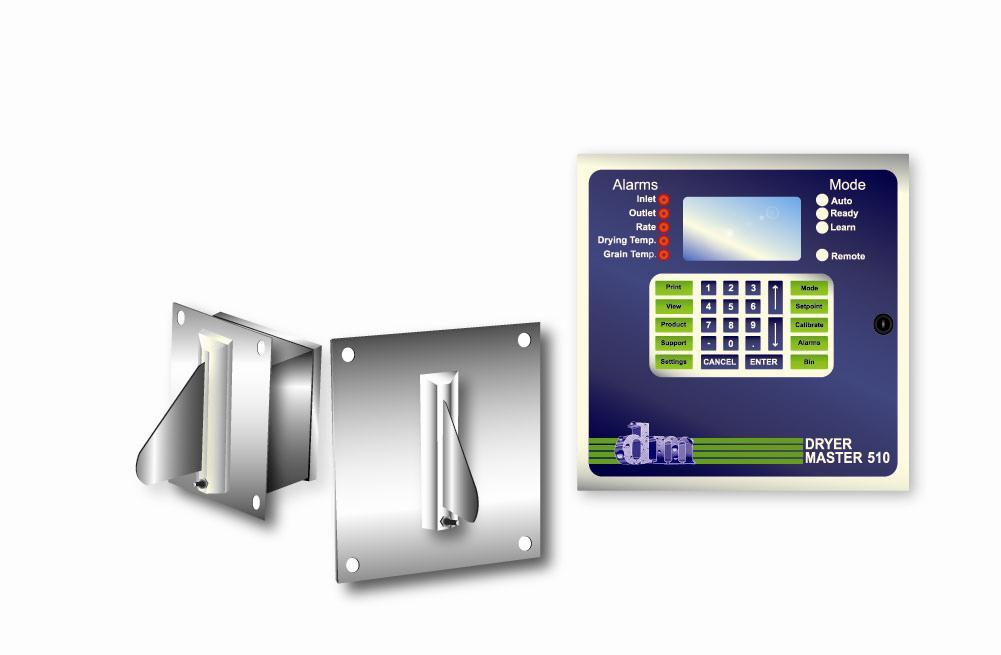
13 System Components The DM510 system includes the following components: DM510 control panel Printer for continuous reporting of dryer operation and results Inlet grain moisture sensor with integral product temperature sensor Outlet grain moisture sensor with integral product temperature sensor Calibration push button Drying air temperature sensor Telephone Call Router, (Optional Item). DM510 Control Panel: The DM510 is a computer system complete with user interface keypad and the display screen, I/O system and telephone modem. The DM510 Control Panel is typically installed in the control room close to the dryer where it can be readily available to the operator. The Printer: The DM510 uses the printer to provide reports such as: Continuous Averages, Hourly Summaries, and Daily Summaries etc. These are tools that can be used to manage the total drying process. Inlet Moisture and Temperature Sensor: The inlet moisture and temperature sensor is installed in the flow of the product before it enters the drying zone (hot zone) of the dryer, typically in the garner or holding bin above the hot zone. Outlet Moisture and Temperature Sensor: The outlet moisture and temperature sensor is installed in the product flow after it exits the cooling area (cold zone) of the dryer. Calibration Push Button: The calibration button is installed near the operator sampling point for product exiting the dryer, usually in close proximity to the outlet moisture sensor. Drying Air Temperature Sensor: A temperature sensor is installed in the heating chamber in close proximity to the dryers existing drying air temperature sensor to monitor the drying air temperature. Telephone call router: The Telephone Call Router (The Stick) automatically routes a call between a Fax Machine and the DM510 modem. This device eliminates the need for a dedicated telephone line for Dryer Master. (This is an optional item.) Page - 13


14 Equipment Schematic Installation Configuration Inlet Moisture sensor Dryer Windows PC Data gathering and remote control ` or Drying Air Temperature sensor Network adapter & router For Ethernet or Internet conectivity or Printer PLC supporting Modbus Serial RTU Telephone line Or Allen Bradley DF1 Dryer Control Panel Drying Rate, Rate setpoint & L/R control switching Calibration button Outlet Moisture sensor Figure 1- Application Schematic Page - 14

15 DM510 User Interface The user interface incorporates three devices, an LCD display screen, status lights (LED s) and the keypad. The following sections describe the operation and functionality for the three components of the user interface. Front Panel Layout Figure 2 - Typical Front Panel Design Page - 15

16 Display Screen The Dryer Master display screen, which provides information for the operator, is located in the upper middle of the door (refer to Figure 2). Most of the time the Main Operations Screen will be displayed, as below. Main Operations Screen Figure 3 Main operations screen displayed items description. Description of Main Operations Screen displayed items 1. Inlet moisture sensor, Product Temperature: The temperature of the product at the top of the dryer as measured by the inlet moisture sensor. 2. Inlet moisture sensor, Product Moisture: The moisture of the product at the top of the dryer as measured by the inlet moisture sensor. 3. Dryer Discharge Rate: The Dryer unload rate as sent to the DM510 by the Dryers unload system. 4. Outlet moisture sensor, Product Moisture: The moisture of the product leaving the dryer as measured by the moisture sensor. 5. Operation Mode: The operator sets the operating mode request. The DM510 will display the message once the system is able to operate in the requested mode. a) Local mode: Dryer in manual operation. The discharge or unload rate is set manually, by the operator, at the dryer panel. b) Manual mode: Dryer in manual operation. The discharge or unload rate is set manually, by the operator, at the DM510. c) Automatic mode: Dryer is in automatic operation. The discharge or unload rate is set automatically by the DM510 to bring the outlet moisture to target. Page - 16
17 6. Outlet moisture sensor, Product Temperature: The temperature of the product leaving the dryer as measured by the moisture sensor. 7. Drying temperature: The temperature of the air in the dryers drying zone of the dryer. This may be referred to as the APT (Air Plenum Temperature). 8. Moisture setpoint: The target moisture for the product leaving the dryer. In Automatic mode the DM510 will attempt to attain this setting by adjusting the Dryers discharge or unload rate. 9. Bin number: The drying bin tracking system permits the user to enter a number for the bin the dryer discharges dried grain into. 10. Product Icon: Different products may be dried in the dryer. The products can be selected from a short list. The product being dried is represented by a small picture (icon). 11. Telephone Modem Icon: The DM510 is able to communicate with the diagnostics services at the Dryer Master Support center. The communication is initiated by the Dryer Master support center and the phone receiver icon is displayed upon successful connection. 12. Print Icon: The printer icon is displayed when a printing task has been initiated. This icon is displayed while the DM510 prepares the information to be printed and until it is sent to the printer. 13. Calibration in progress Icon: The calibration in progress icon is displayed when a calibration is started and the 30 seconds of sampling time has expired, for any and all sensors. The outlet sensor(s) shows the sampling time with the flashing sample button. 14. Suggested Rate message: The suggested rate message is displayed while the system is in local or manual mode and the system is able to predict a reasonable rate. This value is based on the drying factors, the current inlet and outlet moistures, drying temperature and actual discharge speeds. This value serves as a suggested starting point for manual operation. 15. Dryer state message: For effective automatic operation the DM510 goes through stages. These states are, Standby, Primed, Idle Run, Preheat, Running, Holding and Shutdown. The section in this manual Dryer states provides further explanation. 16. Date and time display: Displays the Date and time. 17. Loss of communication message: The message I/O Com. Err displays when the DM510 computer has lost communication with the sensors and other field signals. An alarm and further message will sound within 30 seconds if the DM510 computer is unable to re-establish communication with the I/O system. Page - 17
18 Operation mode description The example screens show the DM510 drying corn in Local Mode, Manual Mode and Automatic mode. Local mode: All items displayed on the Main Operations screen. Dryer discharge is controlled from the dryer panel. Figure 4 Main operations screen (Local Mode) Manual Inlet Outlet Setpoint % % % Rate Drying Temp. Bin Manual mode: All items displayed on the Main Operations screen. Dryer discharge is controlled manually from the DM510 keypad. Suggested Rate: 83.2 Dryer State: Running Time: 2003 / 2/18 10:25 Corn Figure 5 Main operations screen (Manual Mode). Automatic mode: All items displayed on the Main Operations screen. Dryer discharge is controlled automatically by the DM510, based on the moisture setpoint. Figure 6 Main operations screen (Automatic Mode). Page - 18

19 DM510 Keypad Figure 7 Keypad Description of the Keys/Buttons usage and functions 1 Print: Accesses the Print Options menu. Permits setting of print functions, enables or disables reports and sets the print time. 2 View: Accesses the drying history screen. 3 Product: Accesses the Product Selection menu. Permits the selection of the product to be dried. 4 Support: Accesses the System Help menu. Permits the selection of diagnostic screens that allow viewing the values of various signals and states. Used mainly for control diagnostics with the assistance of the Dryer Master support center. 5 Settings: Accesses the Settings menu. Permits the selection of various setup and information screens. For a detailed explanation of the parameters within the screens, refer to Appendix A of this document. 6 Mode: Accesses the Control Mode menu. Permits changing between Automatic Manual and Local control modes. 7 Setpoint: Accesses the Setpoint menu. Permits the selection of the Moisture Setpoint and the Discharge Rate setpoint menu. 8 Calibration: Accesses the moisture sensor selection menu. Permits the entry of manual moisture samples for the purpose of calibrating the DM510 moisture sensors. Page - 19
20 9 Alarms: Accesses the Alarm menu. Permits setting, changing alarms and limits and to view the alarm summary. 10 Bin: Accesses the Bin setting menu. Provides options for selecting, changing the bin and provides bin report printing options. 11 Cancel: Permits cancellation of an operation, acknowledges alarms, clear entries or return to the previous screen. 12 Enter: Permits confirmation and acceptance of data entries or operation changes. 13 Number Keys: Permits entering of numeric values. 14 Arrow Keys: Permits selection of the previous or next available entry field or screen. Page - 20
21 DM510 Status Lights The DM510 includes Alarm and Mode status lights located to the right and left side of the display. These status lights provide important alarm and operation mode indication at a glance. The intent is to supplement information already displayed on the display screen. Figure 8 Display Screen and Status Lights Description of the Status lights 1. Alarms: a) Inlet: Alarm for the inlet moisture. The status light will illuminate RED when the high or low moisture limits are exceeded or there is a fault with the sensor. A descriptive message explaining the alarm will be displayed on the main screen along with an alarm sound. The message and sound can be cleared with the push of the CANCEL key but the status light will remain illuminated until the condition is corrected. b) Outlet: Alarm for the outlet moisture. The status light will illuminate RED when the high or low moisture limits are exceeded or there is a fault with the sensor. A descriptive message explaining the alarm will be displayed on the main screen along with an alarm sound. The message and sound can be cleared with the push of the CANCEL key but the status light will remain illuminated until the condition is corrected. c) Rate: Alarm for the dryers discharge or unload rate. The status light will illuminate RED when the high or low rate limits are exceeded or there is a fault. A descriptive message explaining the alarm will be displayed on the main screen along with an alarm sound. The message and sound can be cleared with the push of the CANCEL key but the status light will remain illuminated until the condition is corrected. d) Drying Temp: Alarm for the drying temperature. The status light will illuminate RED when the high or low rate limits are exceeded or there is a fault. A descriptive message explaining the alarm will be displayed on the main screen along with an alarm sound. The message and sound can be cleared with the push Page - 21
22 of the CANCEL key but the status light will remain illuminated until the condition is corrected e) Grain Temp.: Alarm for both the inlet and outlet product temperature. The status light will illuminate RED when the high or low product temperature is exceeded for either the inlet or the outlet product temperature or there is a fault. A descriptive message explaining the alarm will also be displayed on the main screen along with an alarm sound. The message and sound can be cleared with the push of the CANCEL key but the status light will remain illuminated until the condition is corrected 2. Mode: a) Auto: The Auto status light is illuminated when the DM510 is controlling the dryer Automatically. b) Ready: The Ready status light is illuminated when the DM510 system has gathered sufficient information to be placed into Automatic mode when this status light is lit, the operator can select Automatic Mode. The supervisor can also select Auto Fast Start. When auto fast start is enabled the operator can select Automatic Mode as soon as the learn status light is lit. Great care must be used with this feature, as the DM510 Dryer Master may not have sufficient information to set the correct discharge or unload rate. c) Learn: The Learn status light is illuminated when the dryer is operating and the moisture sensors have product. d) Remote: The Remote Status light is illuminated when the DM510 system is in control of the dryers discharge system either manually or automatically. When this status light is NOT illuminated dryer control is from the dryer panel. Page - 22
23 DM510 Dryer States There are seven Dryer States defined by the DM510 Dryer Master. These are Stand- By, Primed, Idle Running, Shutdown, Preheat, Running, and Holding. The dryer state is displayed in the lower left hand corner of the screen. Description of the Dryer States 1) Stand-By: The dryer fans, discharge conveyor, and burners are off. The dryer may not be full (no moisture displayed by the inlet moisture sensor). 2) Primed: The dryer fans, discharge conveyor, and burners are off. The dryer is full (moisture displayed by the inlet moisture sensor). 3) Idle Running: The dryer fans are on, the discharge conveyor, and burners are off. The dryer is full (moisture displayed by the inlet moisture sensor). This feature is only available on systems that make use of the fan switch input. 4) Shutdown: The dryer is OFF. The fans, discharge conveyor, and burners are off. The dryer is full (moisture displayed by the inlet moisture sensor). This feature is only available on systems that make use of the fan switch input. 5) Preheat: The dryer fans are on; burners are on, the discharge conveyor is off. The dryer is full (moisture displayed by the inlet moisture sensor. 6) Running: The dryer fans are on; burners are on, the discharge conveyor is on. The dryer is full (moisture displayed by the inlet moisture sensor). Moisture displayed at the outlet sensor. 7) Holding: The dryer fans are on; burners are on, the discharge conveyor is off. The dryer is full (moisture displayed by the inlet moisture sensor). This is a temporary state. The DM510 Dryer Master will revert to local mode within 25 minutes and lock out both manual and automatic control from the DM510 Dryer Master as a safety precaution. The DM510 must be reset to clear this lockout. Page - 23
24 Using the DM510 This section discusses the basic elements for operating the DM510. For quick reference, you will find much of the information from this section summarized on your Quick Guide a copy of which is located in Appendix 2 of this document. If at any time you have questions about the operation of the DM510 do not hesitate to contact the Dryer Master Support center at or toll free at (in North America) or Dryer Moisture Systems Inc. at Three Ways to Operate The DM510 Dryer Master can be used in three ways, called Modes of Operation: Local, Manual, and Automatic. It is very important that you understand the differences between the three modes. Description of the Operating Modes Local Every time you start your dryer the DM510 begins in Local mode. In Local mode, the DM510 monitors the drying process and displays information on the screen, but it does not control. In Local mode you operate the dryer from the dryer control panel just as you did before you installed your DM510. Note the Ready status light is NOT illuminated. Manual Auto In Manual, the DM510 monitors the drying process and displays information on the screen, but it does not control. In Manual mode you operate the dryer discharge rate from the DM510. In Manual mode, you can conveniently change the dryer discharge rate directly from the DM510 panel using the Setpoint key. You will typically use Manual mode at startup while the DM510 is learning, or while you are drying short runs, once the Ready status light is illuminated, you can switch to Automatic mode. Automatic mode is where you want to be most of the time. In Automatic mode, the DM510 makes changes to your discharge rate automatically. These changes are based on the process information it receives from the sensors and its model of your drying process. When you switch to Automatic mode, the DM510 will ask you for target moisture. It will then automatically control the discharge rate to dry as much grain as close to your target moisture as possible. In Automatic mode, you will find that your job as operator will become that of a supervisor. You will be responsible for setting the target moisture for the DM510, for setting the limits that it operates under and making sure that the moisture sensors are calibrated. Page - 24
25 ! Note:! DM510 systems with Auto Fast Start enabled can be switched to Automatic mode as soon as the DM510 determines the dryer is running. Should the DM510 select an inappropriate speed, return the system to Manual mode and wait until the 'Ready' status light is illuminated before selecting Automatic. Changing Between Modes Changing between modes is straightforward. Press Mode to display the mode selection menu. Press the up or down arrow keys to highlight your selection followed by the Enter key, or press the number key for the selection. Selecting (1) Request Manual will forward you to the Manual Mode Rate Entry screen. Press Cancel to accept the displayed value and return to the Main Operations screen. Or type in a new value followed by Enter key to return to the Main operations screen using the new rate value. Selecting (2) Request Automatic will forward you to the Automatic Mode Target Entry screen. Press Cancel to accept the displayed value and return to the Main operations screen, or type in a new value followed by Enter key to return to the Main operations screen using the new target value. Selecting (3) Request Local (control at Dryer) will return to the Main operations screen, switch to manual operation at the dryer panel and extinguish the Remote Status light. Choosing a Target Moisture The DM510 does two things based on the target moisture that you provide. First, it observes the discharge moisture in relation to the target to create an image of the drying conditions (dryer model) within the dryer. Second, while in Auto, it manipulates the discharge rate to dry as much grain as close to target moisture as conditions allow. When choosing target moisture, remember that the target moisture is average moisture, not maximum moisture, some grain will come out wetter than the target moisture and some will come out drier. To change the target moisture, press Setpoint to display the setpoint selection menu. Choose (2) Moisture Setpoint to display the Moisture setpoint entry display. Enter new target moisture, press Enter to accept the new value and return to the Main operations screen. Calibrating the DM510 Sensors Reasons for Calibration The DM510 controls your drying based on its moisture sensor readings. For proper operation it is important that the DM510 (on-line) moisture sensors agree with your Page - 25
26 bench top (off-line) moisture tester. This means that for a given sample of grain, both your bench top tester and your DM510 moisture sensor will give a similar moisture reading. While it may sound straightforward to have the on-line DM510 sensor read the same as your bench top unit, there are a few points that make it a little more complex. The DM510 measures the moisture in slightly less than ¼ of a cubic foot (7 liters) of product, in corn at 56lbs/bushel (that equates to about 10lbs (4.5Kg) of corn. The bench top sample is usually less then 250 grams. It is possible to have bench top samples that differ significantly from the reading the DM510 sensor provides. Differences in product temperature and the temperature of the bench top tester and test area will contribute to errors. The heating or cooling of exposed product in the bench top tester and test area will change its moisture. Let s look at an example where an operator takes two moisture samples 20 seconds apart and puts them into two separate containers. If you take the first sample and put it into your bench top sensor, you will get a moisture reading. Now if you put the same sample back into the tester again, you may get a slightly different reading. This is called equipment error and it occurs because most bench top testers have a +/- 0.2% error range. The DM510 moisture sensors have a similar error of +/- 0.2%, so it is possible for the two sensors to read as much as a 0.4% difference and still both be acceptable. If you now take the second moisture sample and put it into the bench top tester you will most likely get another reading. This time the difference is because all the grain coming out of the dryer is not exactly the same moisture. (For example, there are usually variations between different columns in the dryer.) This is called sampling error. This is also evident when taking samples from inbound trucks and it is the reason that you probe and sample from different parts of the truck, the idea being to obtain a representative sample to get accurate overall average moisture. Calibration Procedure While equipment error cannot be eliminated much can be done to reduce sampling error. This is why the DM510 comes with a sampling button for the outlet sensor. The concept is to have the operator and the DM510 take a similar sample over the time the sample button flashes, a period of about 30 seconds. This more representative sample provides a more accurate result. We recommend the following procedure for calibrating the outlet sensor. Check the dryer to make sure grain is flowing past the sensor Push the sample button next to the DM510 outlet sensor (the sample button light will flash for 30 seconds and then remain lit until the sample is entered or cancelled). While the light is flashing, take several small samples and put them into a container (DO NOT take just one sample). Mix up the sample. Test in the bench top tester. Take 3 or more tests and average them. Page - 26
27 Press Calibrate on the DM510 panel to display the Sensor selection menu. The sensor with the sample waiting will show (Sample Waiting) adjacent to its menu entry. Use the arrow keys to highlight the sensor, press the Enter key to move to the data entry screen. The DM510 moisture sensor average for the 30-second test will be displayed. Type in your bench top meter result. Press the Enter key to accept the value and return to the Main operation screen. Type in 0 and Enter or Cancel to clear the calibration in progress and return to the Main operation screen. The DM510 will automatically update its moisture calculation formula. If your bench top reading is more than 1.0% away from the DM510 reading we recommend obtaining a second sample. If the second sample gives a similar result you should enter the calibration and verify the product flow past the sensor.! Note:! The DM510 Moisture sensors are factory calibrated to a standard. New installations can routinely show significantly different readings between the DM510 sensors and the Bench top meter. A number of calibration or an adjustment in the Supervisor Calibration menu will bring the sensors in line. Calibration Frequency Continue sampling at the frequency you are accustomed to. Calibrations can be performed any time there is product in the moisture sensor. The DM510 will track the entries and make adjustments as needed regardless of the operating mode. The Dryer Master support center can use the information to track the performance of the sensor. A good way of seeing if the DM510 is in calibration is to keep a list of calibration pairs. Two columns in which the first column is the bench top reading and the second column is the DM510 reading from the calibration data entry screen. The corresponding readings are beside each other and a glance down the page will tell you if the Dryer Master is calibrated or if there is an outlier. Page - 27
28 Setting Alarms The DM510 comes with an alarm feature that can help you monitor your drying. You can set high and low alarm limits for inlet moisture, outlet moisture, drying air temperature, and discharge rate, inlet and outlet product temperature.! Note:! Alarm settings are provided for safety and operator convenience. Alarms can be made ineffective, however the hazard of making these changes must be weighed against the safety of operators and equipment. For each alarm limit there are two stages of alarm. The first stage is a warning alarm and the second stage is a critical alarm. The warning alarm tells you there may be a situation for you to keep an eye on. In many instances the DM510 will have made changes attempting to correct the situation.! Important:! The DM510 Dryer Master does not try to correct for all situations capable of activating an alarm. Some Dryer Master alarms are for drying environment information only. Operator intervention is often required. If the DM510 cannot correct the situation, a critical alarm will be reached. This will return the DM510 to Manual or Local mode either immediately or after some time. The action is dependent on the nature of the situation.! Note:! It is very important the critical alarms be set in such a way as to allow a reasonable drying environment without impeding the automatic actions of the Dryer Master Page - 28
29 Description of the Alarm Limits operation An example can show this relationship. Target Moisture Critical High Alarm Warning High Alarm Normal Operating Range Warning Low Alarm Critical Low Alarm Time Maximum Operating Range Figure 9 Alarm limits operation Let s assume that your moisture target is 14.5%, and that you want to be notified if the moisture goes above 15.5%, and if the moisture reaches 16%, you want the DM510 to stop controlling and return to Manual mode. For this example you would set your high outlet moisture warning alarm at 15.5% and your high outlet moisture critical alarm at 16.0%. The one exception to how alarms are processed is the discharge rate alarm. For the discharge rate, the alarms displayed in the alarm area are the warning alarms only. The critical alarm limits are displayed and set in the supervisor setup. These alarms will limit the minimum and maximum speeds the DM510 can run your dryer discharge either in automatic or in manual. You should set these limits based on your experience with the dryer, the limits of your grain delivery system and the constraints of your take away system. Remember the DM510 will not and cannot set a discharge rate outside the limits you set in either manual or automatic. For a complete listing of alarm limits refer to the step-by-step key instructions section. Page - 29
30 Changing Products The DM510 is set to dry eight (8) different products and is typically configured to dry Corn, Beans, Wheat, Canola/Rapeseed or other, Corn Hot or Other, Beans or Other, Sunflower or Other, and Rice or Other. The or other designation suggests that the product selection may be used for the named product or any product. For each product a unique list of information and parameters is used, this includes calibration of the moisture sensors for that product. It is therefore important that you dry using the correct product setting. The product name as well as the graphical representation (icon) of the currently selected product is located at the bottom right corner of the main operations screen. To select/change the product press the Product key. The Select Product menu will display, press the arrow keys to highlight the product, press the Enter key or press the number key adjacent to the selection to accept the choice and return to the Main operations screen. What to expect when the DM510 is turned on The startup sequence of the DM510 takes 1 to 2 minutes. At this time the DM510 CPU tests various components and loads the DM510 Dryer Master system software. The alarm may sound momentarily, the alarm and mode Status lights will sequence. The main screen will blank, followed by the appearance Dantec logo, then possibly a continuous alarm and the Main operations screen. With the dryer not running a number of alarms may occur, these may display a message on the Main Operations Screen, sound the alarm and possibly illuminate alarm status lights. The alarm sound and message can be cleared with the press of the Cancel key. The DM510 stores the current operation information, makes Operation Backups on a daily basis and System Backups on a weekly basis. This ensures the DM510 system is able to restart full control within one dryer load after a shutdown or power failure. Because the DM510 Dryer Master is a computer system, for added security, it requires a computer UPS (Uninterruptible Power Supply) to bridge momentary power outages.! Note:! The DM510 Dryer Master should remain powered for the duration of the dying season. Turning off the DM510 Dryer Master will cause interruptions in system backups that take place at midnight every day. Page - 30
31 The First Week of Drying The Dryer Master Support center can assist you by fine-tuning your new DM510 Dryer Master during the first week of drying, through the following three stages. 1. Calibrating the sensors. During the first 24 hours of drying we recommend that you take a minimum of 10 samples and input the results into the DM510. The DM510 should NOT be operated in automatic at this time. Follow the calibration procedure previously described for best results. This will help ensure that the DM510 moisture readings are in line with your Bench Top tester readings and it will also familiarize you with entering calibrations. The objective is to make you comfortable with the moisture readings provided by the DM510. During this time you should become comfortable with the DM510 operation by setting and changing the discharge rate, in Manual mode, using the DM510 keypad. 2. Verifying the Throughput The DM510 is collecting operating and performance data from the dryer while operating in Manual mode; after 24 hours there is usually sufficient data for the Dryer Master to recommend a discharge rate: when the Dryer Master recommended rate is similar to that being run. The system is ready to be put into automatic mode. It will also be of benefit if the throughput of the Dryer is verified by running product into a holding bin for a period of time. This will permit the verification of the dryer manufactures throughput specification. The throughput is the volume of grain that goes through your dryer, in one hour, at a specific rate. The correct holding volumes and throughput are of paramount importance for good Automatic operation. 3. Drying in Automatic When the Dryer volumes and throughput have been reviewed and confirmed, after the initial 24 hours of operation and the information matches the dryer specifications and installed information, and you are comfortable with the DM510 moisture readings, it is acceptable to use Automatic mode. Periodically during the drying season the Dryer Master Support Centre may contact you to ensure your DM510 is operating correctly, and to answer any questions you may have. If you have questions or concerns, please do not hesitate to contact the Support Centre at or (Toll free in North America) Page - 31
32 A Typical Daily Routine The following steps should be included in your routine when using the DM510: 1. Before dryer start-up, check the outlet moisture sensor to ensure it is clean and free of debris. The sensor chute has no obstructions ahead of the sensor. The flow-metering device if so equipped is operating. The flow restrictor if so equipped is installed. 2. Start your dryer as you have in the past from the dryer control panel. The DM510 panel will indicate that you are in Local mode. 3. At the DM510 panel, press the Mode key, select Request Manual mode. The Manual Mode rate entry screen will appear. Press Cancel to accept the displayed discharge rate and return to the Main Operations Screen, or type in a new value followed by the Enter key to accept the new value and return to the Main Operations Screen. 4. While in manual mode the rate can be changed via the Setpoint key menu. 5. Automatic can be selected when the Ready Status light is illuminated, to select Automatic press the Mode key, select Request Automatic mode. The Automatic Mode moisture setpoint selection screen appears. Press Cancel to accept the displayed moisture setpoint and return to the Main operations screen, or type a new value followed by the Enter key to accept the new value and return to the Main Operations Screen. 6. While in automatic mode the moisture setpoint can be changed via the Setpoint key menu. 7. The DM510 will now automatically adjust the dryer discharge rate to achieve the displayed product target moisture. 8. Periodically check the moisture sensors to ensure they are clean and there is good product flow. 9. While operating the dryer, calibrate the moisture sensors as required. 10. When you turn off the dryer, the DM510 will automatically revert to Local mode after some period of time. If this is not occurring the DM510 does not sense the Dryer as being OFF. Verify and correct the DM510 alarm and limit settings. Page - 32
33 A Typical Yearly Routine Start-Up Check List 1) Connect the phone line to the DM510 by plugging the telephone line from the wall jack, through the surge protector and into the DM510 jack marked Line (These jacks are located on the bottom of the DM510). 2) Plug the printer into its power outlet and connect the printer cable to the Printer port at the bottom of the DM510 3) Your System may have a connection plugged into the Terminal port at the bottom of the DM510. 4) Turn the DM510 on. It will take the DM510 a few minutes to go through its startup sequence. 5) Acknowledge any alarm messages. (There may be several alarms if the dryer is not running). 6) If this is the first season for your DM510 Dryer Master or you have purchased the ESP (Extended Support Program) contact the Dryer Master Support Centre and tell them that you are ready to dry for the season. The Support Centre will help you verify that your equipment is in full working order. Shutdown Check List 1) If this is the first season for your DM510 Dryer Master or you have purchased the ESP (Extended Support Program) contact the Dryer Master Support Centre to let them know you are finished drying for the season. They can then download the drying information stored in your DM510. 2) Verify with the Support Centre that the download was successful. 3) Unplug the phone lines from the DM510. 4) Turn the DM510 off using the power switch on the bottom of the control panel. Do not unplug the DM510 from the wall outlet. The ground connection should remain in place for surge protection. 5) Unplug the printer and disconnect the printer cable from the DM510. Store the printer in a moisture and dust free area. 6) Your System may have a connection plugged into the Terminal port at the bottom of the DM510. Unplug this connection also Page - 33
34 DM510 Function & Usage The system function and usage has been set-up with the most used functions at the beginning of this section. Also note that the key function is affected by the operating state of the system. Mode key MODE 1 Request Manual DISCHARGE SPEED SETPOINT 2 Request Automatic MOISTURE SETPOINT 3 Request Local Figure 10 Mode key Hierarchy There are 3 operating modes: Manual (Manual control at the DM510), Automatic (DM510 set the discharge rate) and Local (Manual control at the Dryer Panel). Press Cancel at any time to return to the Main Operations Screen.! Note:! DM510 systems with Auto Fast Start enabled can be switched to Automatic mode as soon as the DM510 determines the dryer is running. Should the DM510 select an inappropriate speed, return the system to Manual mode and wait until the 'Ready' status light is illuminated before selecting Automatic. Page - 34
Dryer Master DM510 Users Guide
 Dryer Master DM510 Users Guide Dryer Moisture Systems Inc. 115 Ardelt Ave. Kitchener, Ontario Phone 519.725.4700 Fax 519.885.4300 USA & Canada Toll Free 1-888-318-0009 E-mail: info@dryermaster.com Reminder
Dryer Master DM510 Commissioning Guide
 COMMISSIONING GUIDE Dryer Master DM510 Dryer Moisture Systems Inc. 640 Superior Drive Waterloo, Ontario Phone 519.725.4700 Fax 519.885.4300 USA & Canada Toll Free 1-888-318-0009 E-mail: info@dryermaster.com
Dryer Master DM510 Installation Guide
 INSTALLATION GUIDE Dryer Master DM510 Installation Guide Dryer Moisture Systems Inc. 115 Ardelt Avenue, Kitchener, Ontario Phone 519.725.4700 Fax 519.885.4300 USA and Canada Toll free at 1-888-318-0009
Dryer Master Inc. Dryer Master AM 3. Product Manual
 Dryer Master Inc. Dryer Master AM 3 Revision 1.0 July, 2008 Revision 1.2 February, 2009 Revision 1.3 March, 2009 Revision 1.4 September, 2013 Prepared by: Dryer Master Inc. Dryer Master Inc 2008, 2009,
3. Turn on the electrical power supply to the dryer, and move the safety disconnect handle mounted on the dryer s upper power box to on.
 DRYER OPERATION - START-UP INITIAL SETUP PARAMETERS Turn the control power switch to on. When the Boot Screen appears touch the START DRYER button. The computer will run a quick check of the system network
QuadraTouch Pro Software Manual Dryer Control System
 QuadraTouch Pro Software Manual Dryer Control System Software is constantly changing. Make sure you are up to date with Sukup s newest software. New software and manuals are available for download at:
Portable Dryer Touch Screen Controls
 Portable Dryer Touch Screen Controls and Reference Manual PNEG 1509 PNEG 1509 Date: 1 23 08 Reference Table of Contents TABLE OF CONTENTS DRYER SAFETY & DRYER INFORMATION...4 SPECIAL SETUP SCREENS...5
Peak Partners Web-Programmable Thermostat Homeowner s Manual. Look inside for a complete guide to the setup and operation of your new thermostat.
 Peak Partners Web-Programmable Thermostat Homeowner s Manual Look inside for a complete guide to the setup and operation of your new thermostat. Table of Contents Step 1: Getting Started...4-6 A. Thermostat
IT801 Thermostat. User s Manual. The complete guide to the set up and operation of your new smart Wi-Fi thermostat.
 IT801 Thermostat User s Manual The complete guide to the set up and operation of your new smart Wi-Fi thermostat. The smart Wi-Fi thermostat system learns your comfort preferences, then finds opportunities
ZX1e ZX2e ZX5e. Document No Issue 01 user manual
 ZX1e ZX2e ZX5e Document No. 996-130 Issue 01 user manual MORLEY-IAS ZX2E/ZX5E Fire Alarm Control Panels Table of Contents 1 INTRODUCTION... 4 1.1 NOTICE... 4 1.2 WARNINGS AND CAUTIONS... 4 1.3 NATIONAL
User s Manual. TIGER S EYE E-Series Mark V Jockey. TIGERFLOW Systems, Inc Mint Way Dallas, Texas
 User s Manual TIGER S EYE E-Series Mark V Jockey TIGERFLOW Systems, Inc. 4034 Mint Way Dallas, Texas 75237 214-337-8780 www.tigerflow.com TABLE OF CONTENTS Introduction... 4 Sequence of Operation... 5
User Manual. Dryer Controller M720
 User Manual Dryer Controller M720 Hardware version 1.00 Software version 1.00 Preliminary version Manual M720 Dryer controller Page 1 of 42 Document history Preliminary version: - Created in April, 2009
Dryer Controller M720
 User Manual Dryer Controller M720 Hardware version 2.00 Software version 2.00 Manual M720 Dryer controller Page 1 of 60 Document history Preliminary version: - Created in April, 2009 Hardware Version 2.00,
Refrigeration Controller Operator s Manual (HRC) PO Box 6183 Kennewick, WA
 PO Box 6183 Kennewick, WA") Refrigeration Controller Operator s Manual (HRC) PO Box 6183 Kennewick, WA 99336 www.jmcvr.com 1-509-586-9893 Table of Contents TABLE OF FIGURES...1 OVERVIEW OF THE HRC CAPABILITIES...2 INSTALLATION AND
Refrigeration Controller Operator s Manual (HRC) PO Box 6183 Kennewick, WA 99336 www.jmcvr.com 1-509-586-9893 Table of Contents TABLE OF FIGURES...1 OVERVIEW OF THE HRC CAPABILITIES...2 INSTALLATION AND
U ser's Guide PC6010
 User's Guide PC6010 Quick Reference Guide This manual is for Basic and Advanced users. Each of these types of user can access a different set of functions. The and symbols next to the title of each procedure
Halton SAFE / 7.14 user guide and installation instructions
 Halton SAFE / 7.14 user guide and installation instructions VERIFIED SOLUTIONS BY H A LTO N Enabling Wellbeing Table of contents 1 System description 3 2 User Accounts 4 3 Main menu 7 3.1 Main menu - Change
Interactive Fire Control Panel IFS7002 four signal loops Instruction Manual
 Interactive Fire Control Panel IFS7002 four signal loops Instruction Manual Revision 6/01.17 Contents 1. Introduction... 6 2. Terminology... 6 3. Function... 8 4. Technical data... 8 4.1. Physical configuration...
Dryer Moisture Systems Inc. Dryer Master M 2. Product Manual
 Dryer Moisture Systems Inc. Dryer Master M 2 Revision 1. January, 27 Revision 1.1 March, 27 Revision 1.2 June, 27 Revision 1.22 July, 27 Revision 1.22.1 January, 28 Revision 1.22.2 April, 28 Revision 1.23
Vision for Portable Dryers
 Vision for Portable Dryers Operation Manual PNEG-1739 Date: 06-21-10 PNEG-1739 2 PNEG-1739 Vision for Portable Dryers Table of Contents Contents Chapter 1 Safety...5 Safety Guidelines... 5 Dryer Operation...
Substation Monitoring System
 Substation Monitoring System SF6 Gas Density Monitoring System Description Introduction As a result of recent European legislation on the control of greenhouse gasses, utilities and manufacturers alike
TABLE OF CONTENTS. Principle of operation of CAFM...1. Installation instructions...2. Main ADC Operating screen...3. Set process temp and Setback...
 TABLE OF CONTENTS Principle of operation of CAFM....1 Installation instructions......2 Main ADC Operating screen......3 Menu definitions of ADC control Set process temp and Setback.....4 7-Day timer and
Algo-Tec 6500/6600 INTERACTIVE ADDRESSABLE FIRE CONTROL SYSTEM
 Algo-Tec 6500/6600 INTERACTIVE ADDRESSABLE FIRE CONTROL SYSTEM (1-4 LOOPS) USER MANUAL Protec Fire Detection plc, Protec House, Churchill Way, Nelson, Lancashire, BB9 6RT, ENGLAND +44 (0) 1282 717171 www.protec.co.uk
Operations Manual TS400. Test Station for G450/G460 Gas Detector
 TS400 Test Station for G450/G460 Gas Detector Operations Manual 1194 Oak Valley Dr, Ste 20, Ann Arbor MI 48108 USA (800) 959-0329 (734) 769-0573 www.goodforgas.com GfG Products for Increased Safety Congratulations
The Kryos LN2 Liquid Level Control & Cryogenic Temperature Control
 The Kryos LN2 Liquid Level Control & Cryogenic Temperature Control Created for Taylor-Wharton Gas Equipment By Pacer Digital Systems, Inc. INTRODUCTION... 4 TEXT FORMAT NOTATION... 4 SYSTEM COMPONENTS...
Operational Overview and Controls Guide
 DOCUMENT: ECSEQ2-2 EFFECTIVE: 02/26/10 SUPERSEDES: 02/14/07 Operational Overview and Controls Guide Standard Two or Three Pump Type VFD Booster Controls 6700 Best Friend Road. Norcross, GA 30071. (770)
Thermostat Guide Online Guide Brighten Conservation Program. Personal Reference Guide. Brighten ithermostat
 Thermostat Guide Online Guide Brighten Conservation Program Personal Reference Guide Brighten ithermostat Thermostat Guide Online Guide Brighten Conservation Program Welcome to your new Brighten ithermostat
OPERATING MANUAL. EchoTherm PROGRAMMABLE DIGITAL CHILLING INCUBATOR MODELS IN35, IN45 and IN55-12VDC. DOCUMENT NUMBER IN35-03 Revised 15 May 2015
 OPERATING MANUAL EchoTherm PROGRAMMABLE DIGITAL CHILLING INCUBATOR MODELS IN35, IN45 and IN55-12VDC DOCUMENT NUMBER IN35-03 Revised 15 May 2015 TORREY PINES SCIENTIFIC, INC. 2713 Loker Ave. West Carlsbad,
DELOMATIC 400, DM-400 HYDRO
 Delomatic 400 HYDRO controller OPERATOR S MANUAL DELOMATIC 400, DM-400 HYDRO Functional description User interface Log books Alarm handling Document no.: 4189340880A SW version 1.0 or later Table of contents
3500 CONVENTIONAL FIRE ALARM CONTROL PANEL
 3500 CONVENTIONAL FIRE ALARM CONTROL PANEL USER MANUAL Protec Fire Detection PLC, Protec House, Churchill Way, Nelson, Lancashire, BB9 6RT. Telephone: +44 (0) 1282 717171 Fax: +44 (0) 1282 717273 Web:
No part of this publication may be reproduced, stored in an automated data file or made public in any form or by any means, whether electronic,
 No part of this publication may be reproduced, stored in an automated data file or made public in any form or by any means, whether electronic, mechanical, by photocopying, recording or in any other manner
HIGH EFFICIENCY FIRETUBE CONDENSING GAS BOILER
 This manual must be left with owner and should be hung on or adjacent to the boiler for reference. US HIGH EFFICIENCY FIRETUBE CONDENSING GAS BOILER MODELS CHS-85 through CHS-399 APPENDIX A CONTROLLER
Computer Room Guard Model VM Manual and Installation Instructions
 Computer Room Guard Model VM500-8 Manual and Installation Instructions For units purchased since December 2004 Index Page General Description 3 Installation, Wiring Diagram 3-5 Accessing the Computer Room
APC BC300 Series 40kW 208/450/480V User Guide
 APC BC300 Series 40kW 208/450/480V User Guide Copyright 2002 APC Denmark ApS This manual is subject to change without notice and does not represent a commitment on the part of the vendor Thank You Thank
OPERATING MANUAL MOLECULAR DIMENSIONS, INC. PROGRAMMABLE DIGITAL CHILLING INCUBATOR MODELS MD5-601 AND MD5-603
 OPERATING MANUAL MOLECULAR DIMENSIONS, INC. PROGRAMMABLE DIGITAL CHILLING INCUBATOR MODELS MD5-601 AND MD5-603 DOCUMENT NUMBER DM5-601/603-1 January 21, 2011 MOLECULAR DIMENSIONS, INC. United Kingdom Office
Covidien Articulating Absorba Tack Foil Pouch Leak Tester Owner s Manual IPE SN Rev 1
 Covidien Articulating Absorba Tack Foil Pouch Leak Tester Owner s Manual IPE SN 12497 Rev 1 MANUFACTURER: INNOVATIVE PRODUCTS & EQUIPMENT, INC. 5 PROGRESS AVE TYNGSBORO, MASSACHUSETTS 01879 U.S.A Revision
Model: Available in: Sapphire Black and Glacier White. 1 Series
 Model: Available in: Sapphire Black and Glacier White 1 Series Table of Contents Product Image Table of Contents What is a Programmable Room Thermostat? Installation Procedure Mode Select Pairing the neohub
Focus 4010\ Focus 4010 HT porcelain firing furnace
 INSTRUCTION MANUAL Focus 4010\ Focus 4010 HT porcelain firing furnace Warning You have available one of the most precise dental furnaces equipped with a heating muffle made by the original manufacturer
Programmable Interactive User Manual
 67504B 02/16 (ALA) DH E RT 102/BW Programmable Interactive User Manual www.schluter.com 1. Contents 2. Menu Overview..............3 3. Introduction................ 4 4. General Operation............5 4.1.Navigation
PHASE NON-COIN USER S MANUAL (S.A.F.E.)
") PHASE 7.2.2 NON-COIN USER S MANUAL (S.A.F.E.) American Dryer Corporation 88 Currant Road Fall River, MA 02720-4781 Telephone: (508) 678-9000 / Fax: (508) 678-9447 E-mail: techsupport@amdry.com www.amdry.com
PHASE 7.2.2 NON-COIN USER S MANUAL (S.A.F.E.) American Dryer Corporation 88 Currant Road Fall River, MA 02720-4781 Telephone: (508) 678-9000 / Fax: (508) 678-9447 E-mail: techsupport@amdry.com www.amdry.com
Model: 1 Series 12V. Available in: Sapphire Black and Glacier White
 Model: Available in: Sapphire Black and Glacier White 1 Series Table of Contents Product Image Table of Contents What is a Programmable Room Thermostat? Installation Procedure Mode Select Pairing the neohub
Refrigerated air dryers
 Refrigerated air dryers OPERATING AND MAINTENANCE MANUAL Original instructions 38178800319 OPERATING AND MAINTENANCE MANUAL - Contents 1 CONTENTS CONTENTS... 1 Chapter 1 IDRY ELECTRONIC CONTROLLER...
LOUP II DRILL MONITOR OPERATION MANUAL. SOFTWARE v45
 LOUP II DRILL MONITOR OPERATION MANUAL SOFTWARE v45 Service and Technical Support Contact: Loup Electronics Inc. Address: 2960 N. 38th Street Lincoln, NE 68504 Phone: 877-489-LOUP(5687) 402-464-7131 Fax:
6100 SINGLE LOOP DIGITAL ADDRESSABLE FIRE ALARM CONTROL PANEL
 6100 SINGLE LOOP DIGITAL ADDRESSABLE FIRE ALARM CONTROL PANEL USER MANUAL Protec Fire Detection plc, Protec House, Churchill Way, Nelson, Lancashire, BB9 6RT. Telephone: +44 (0) 1282 717171 Fax: +44 (0)
2) This manual covers Fire and General Alarm systems. The differences are described in the appropriate sections.
 This manual covers Fire and General Alarm systems. The differences are described in the appropriate sections.") ISSUES ISSUE DATE RELEASED DETAILS OF CHANGE AUTHOR 4 Rev 2 September 2004 Changes for 4000 series. DB 4 Rev 3 April 2005 Screen shots updated and other minor changes K.Z. 4 Rev 4 September 2006 4 Rev
ISSUES ISSUE DATE RELEASED DETAILS OF CHANGE AUTHOR 4 Rev 2 September 2004 Changes for 4000 series. DB 4 Rev 3 April 2005 Screen shots updated and other minor changes K.Z. 4 Rev 4 September 2006 4 Rev
MODEL SF-10 CONTROL OPERATION AND INSTRUCTION MANUAL
 MODEL SF-10 CONTROL OPERATION AND INSTRUCTION MANUAL The SF-10 Temperature Control () is an efficient boiler operator with a digital LCD display with backlight, a boiler pump output, and an alarm. The
Centroid Snet 2. Battery Management Software. User Manual V1.1. Eagle Eye Power Solutions, LLC Keeping an Eye on Your Critical Power!
 Eagle Eye Power Solutions, LLC Keeping an Eye on Your Critical Power! Centroid Snet 2 Battery Management Software User Manual V1.1 www.eepowersolutions.com Tel: 1-877-805-3377 info@eepowersolutions.com
LineGuard 2300 Program User Manual (FloBoss 107)
") Form A6251 Part Number D301346X012 November 2012 LineGuard 2300 Program User Manual (FloBoss 107) Remote Automation Solutions Revision Tracking Sheet November 2012 This manual may be revised periodically
Form A6251 Part Number D301346X012 November 2012 LineGuard 2300 Program User Manual (FloBoss 107) Remote Automation Solutions Revision Tracking Sheet November 2012 This manual may be revised periodically
Laptop / PC Programming Manual
 Laptop / PC Programming Manual Doc. # Fire PC Program rev B 01.07 This Document is property of Evax Systems, Inc. The Evax Fire Solutions Programmer Components 2 1.0 System Setup 4 1.1 Interface Setup
DRI-AIR INDUSTRIES, INC. AHM-1C HOPPER MOUNT DRYER OPERATING MANUAL
 AHM-1C HOPPER MOUNT DRYER OPERATING MANUAL Page 1 DRI-AIR INDUSTRIES, INC. 16 THOMPSON ROAD P.O. BOX 1020 EAST WINDSOR, CT 06088-1020 Tel. (860) 627-5110 FAX (860) 623-4477 Internet http://www.dri-air.com
Operating instructions V-ZUG-Home
 Operating instructions Thank you for choosing an appliance with. meets high demands and is easy to use. Nevertheless, please take the time to read these operating instructions in order to familiarize yourself
Dryer Moisture Systems Inc. Dryer Master GM 2. Product Manual. Revision 1.0 January, 2007 Revision 1.01 March, Prepared by:
 Dryer Moisture Systems Inc. Dryer Master GM 2 Revision 1. January, 27 Revision 1.1 March, 27 Prepared by: Dryer Moisture Systems Inc. Dryer Moisture Systems Inc. Page: 2 Table of Contents 1 INTRODUCTION...
Energy Plannersm Programmable Thermostat Customer Guide. Take control of your comfort and energy savings
 Energy Plannersm Programmable Thermostat Customer Guide Take control of your comfort and energy savings BLANK PLACEHOLDER FOR INSIDE FRONT COVER DO NOT PRINT Contents Introduction About this Guide... 1
Interactive Fire Control Panel IFS7002 one signal loop Instruction Manual
 Interactive Fire Control Panel IFS7002 one signal loop Instruction Manual Revision 4/01.17 Contents 1. Introduction... 6 2. Terminology... 6 3. Function... 8 4. Technical data... 8 4.1. Physical configuration...
Operation Manual Fighter ProVision Software. Version: 0.0 Revision: 1
 Operation Manual Fighter ProVision Software Version: 0.0 Revision: 1 TABLE OF CONTENTS 1. Introduction 5 2. Software Installation 5 3. PC Users 6 3.1 Introduction 6 3.2 Default Code 6 3.3 Edit PC User
Operations Manual. Automated Fuel Maintenance System FTI-5A SINGLE TANK FUEL TECHNOLOGIES INTERNATIONAL
 Operations Manual Automated Fuel Maintenance System FTI-5A SINGLE TANK FUEL TECHNOLOGIES INTERNATIONAL 05/01/2016 Rev A Fuel Technologies FTI-5A Single Tank Controller Programming And Operating Instructions
RPM1600 Series Room Pressure Monitors
 RPM1600 Series Room Pressure Monitors Technical Bulletin LB-RPM1611-0, LB--0 Code No. LIT-12012228 Issued October 2017 Refer to the QuickLIT website for the most up-to-date version of this document. How
Exercise 8. Controlling a Batch Mixing Process EXERCISE OBJECTIVE
 Exercise 8 Controlling a Batch Mixing Process EXERCISE OBJECTIVE To create a ladder program for controlling a batch mixing process. To test program operation through the completion of verification steps.
Omniguard 4: Features
 OMNIGUARD 4 The clear choice for monitoring and documenting Vacuum and Pressure in a containment area. Ideal for Asbestos, Lead and Mold abatement and Clean Room monitoring. Omniguard 4: Features The Omniguard
Using Your. Security System With LED Keypad S5030, S5031, S5032
 Using Your Security System With LED Keypad S5030, S5031, S5032 Contents 1 Overview Your Security System... 1 How Your Security System Works... 2 Your System's Programming... 3 Getting Used to Your System...
The Information Contained in this Document is Proprietary and should only be used for Service or Training of Authorized Blodgett Servicers who will
 The formation Contained in this Document is Proprietary and should only be used for Service or Training of Authorized Blodgett Servicers who will be working on the Blodgett XR8 Oven. All other uses are
Ice Rink (Single and Dual Configurations) Custom Control Features
 Custom Control Features") & M&M Refrigeration, Inc. Computer Control System Ice Rink (Single and Dual Configurations) Custom Control Features REVISION DATE DESCRIPTION - 4/20/05 Original release. A 09/21/98 Update Chiller Pump
& M&M Refrigeration, Inc. Computer Control System Ice Rink (Single and Dual Configurations) Custom Control Features REVISION DATE DESCRIPTION - 4/20/05 Original release. A 09/21/98 Update Chiller Pump
Monitoring Software for NPBC-V3M-1 User Manual
 Monitoring Software for NPBC-V3M-1 User Manual User Manual ver 1.5 page 1 of 14 Contents: 1. Introduction... 3 2. Requirements... 3 3. Installing the software... 4 4. Connecting the devices... 4 5. Updating
Tempered Water Logic Control OPERATION l TROUBLE SHOOTING
 Tempered Water Logic Control OPERATION l TROUBLE SHOOTING English For MPE Multiple Chiller Units Control Panel TEMPERED WATER SYSTEMS L-2199 Rev. 20080223 Revision: L-2199 20101104 *** IMPORTANT NOTICE
Fire Control Panel FS5100
 Fire Control Panel FS5100 INSTRUCTION MANUAL Revision 6/02.11 Contents 1. Introduction... 5 2. Terminology... 5 3. Function... 7 4. Technical data... 7 4.1. Modules... 7 4.1.1. Type of modules... 7 4.1.2.
AGC 200 Advanced Gen-set Controller OPERATOR S MANUAL
 Advanced Gen-set Controller OPERATOR S MANUAL Display readings Push-button functions Alarm handling Log list Document no.: 4189340607A SW version 3.5X.X or later Table of contents 1. ABOUT THIS DOCUMENT...3
Model: Edge-HC. 1 edge-hc
 Model: Model: Edge-HC 1 edge-hc Table Of Contents Product Image Table of Contents Installation Procedure System Type LCD Display Power On/OFF Setting the Time & Date Mode Select Fan Speed Temperature Display
THX-DL Data Logger USER & INSTALLATION MANUAL V
 THX-DL Data Logger USER & INSTALLATION MANUAL V1.2012 www.thermomax-refrigeration.com Contents PRESENTATION Summary of Features 2 INSTALLATION Safety Precautions 4 THX Unit 4 Sensors 4 Alarm Relay 4 Power
Manual# User s Manual. DCU 410/408 Engine Control Unit RP 410 Remote Panel FW 2.3
 Manual# 1100268 User s Manual DCU 410/408 Engine Control Unit RP 410 Remote Panel FW 2.3 Table of Content GENERAL INFORMATION... 3 ABOUT THIS MANUAL... 3 400 SERIES OVERVIEW... 3 Available Modules...
Adaptive CyCLO Technical and HMI User Guide. CyCLO User Guide. Version th December 2017 REV
 CyCLO User Guide Version 2.00 19 th December 2017 REV 2.00 1 Contents 1. Hardware... 3 1.1. Introduction... 3 1.2. Electrical Specification... 3 1.3. Board Overview... 4 1.4. Electrical Installation...
CELLTROL II BIOREACTOR CONTROL SYSTEM OPERATIONS MANUAL
 Operation Manual Celltrol II Bioreactor Control System Page 1 of 33 Table of Contents 1) Introduction... 3 1.1) Scope of Document... 3 1.2) Control System Overview... 3 1.3) Introduction to Celltrol II...
Table of Contents. Model: Series. Available in : Sapphire Black and Glacier White. Product Image. 20 Table of Contents.
 1 Model: Available in : Sapphire Black and Glacier White Table of Contents Product Image 1 Frost Protection 20 Table of Contents 2 Power ON/OFF 21 What is a Programmable Room Thermostat? Installation Procedure
Climapro 2. User manual. wireless room thermostat without receiver. To be left with the user.
 Climapro 2 User manual To be left with the user wireless room thermostat without receiver www.glow-worm.co.uk table of contents READ CAREFULLY BEFORE USING 1 Introducing your Climapro 2... 3 1.1 Description...
MPT Electric Fire Pump Controller
 Setup and Operating Instructions MPT Electric Fire Pump Controller This manual provides general information, installation, operation, maintenance, and system setup information for Metron MPT Electric Fire
ModSync Sequencing System Installation & Operation Manual. For use with Fulton Steam Boilers.
 ModSync Sequencing System Installation & Operation Manual For use with Fulton Steam Boilers. Revision 3.0 8/21/2008 - 2 - Table of Contents Introduction Page 4 Features Page 4 Sequence of Operation Page
KFP-CF Series Operation Manual
 KFP-CF Series Operation Manual P/N 501-415103-2-31 REV 03.10 ISS 13NOV13 Copyright Trademarks and patents Manufacturer Version Certification European Union directives Contact information 2013 UTC Fire
1 and 2 Fan Vision Series Portable Dryers
 1 and 2 Fan Vision Series Portable Dryers Operator s Manual PNEG-1456 Date: 09-29-09 PNEG-1456 2 PNEG-1456 1 and 2 Fan Vision Series Portable Dryers Table of Contents Contents Chapter 1 Safety... 5 Safety
V1.21: (Required for All Dryers with Static Sampler or Incoming MST Sensor, Good for All Dryers)
") QuadraTouch Pro Software Update Change Log Official Release vs. Beta Release (How to tell): Tools -> System Tools -> System Information and look for Official Release or Beta Release in the bottom right
QuadraTouch Pro Software Update Change Log Official Release vs. Beta Release (How to tell): Tools -> System Tools -> System Information and look for Official Release or Beta Release in the bottom right
Refrigeration and Air Conditioning Controls. User s manual. Degree Master Controller in AKC 55 Systems ADAP-KOOL REFRIGERATION AND AIR CONDITIONING
 Refrigeration and Air Conditioning Controls User s manual Degree Master Controller in AKC 55 Systems ADAP-KOOL REFRIGERATION AND AIR CONDITIONING Table of Contents Introduction p. 3 Configuring the host
Product Manual SZ1009
 Product Manual SZ1009 Conventional Heating & Cooling Thermostats with Heat Pump Mode Communicating Thermostats Description The SZ1009 is a microprocessor-based mable thermostats designed for conventional
Table of Contents. Product Image Table of Contents What is a Programmable Room Thermostat? Installation Procedure
 1 Model: 1 Table of Contents Product Image Table of Contents What is a Programmable Room Thermostat? Installation Procedure 1 2 3-4 5-6 Mode Select Pairing the ProTouch iq Hub Pairing the ProTouch iq What
FreezeAlarm Dialer Pro
 FreezeAlarm Dialer Pro User Manual for FA-800E Thank you for purchasing our FreezeAlarm Dialer Pro. This instruction manual covers installation for model FA-800E. General Description The FA-800E automatically
AUTO CM CM USER GUIDE
 1 2 3 4 5 6 7 AUTO CM701...2-6 CM707...7-11 USER GUIDE CM701 - USER GUIDE Description The Honeywell CM701 is a programmable room thermostat designed to control your heating system efficiently, providing
MODEL EM-10 ELECTRIC BOILER CONTROL OPERATION AND INSTRUCTION MANUAL
 MODEL EM-10 ELECTRIC BOILER CONTROL OPERATION AND INSTRUCTION MANUAL The EM-10 Boiler Temperature Control (BTC) is an efficient boiler operator with a digital LCD display with backlight, a boiler pump
DRI-AIR INDUSTRIES, INC. ARID-X10C FLOOR MOUNT DRYER OPERATING MANUAL
 ARID-X10C FLOOR MOUNT DRYER OPERATING MANUAL Page 1 DRI-AIR INDUSTRIES, INC. 16 THOMPSON ROAD P.O. BOX 1020 EAST WINDSOR, CT 06088-1020 Tel. (860) 627-5110 FAX (860) 623-4477 Internet http://www.dri-air.com
Follett Performance Plus
 Follett Performance Plus touchscreen user guide The next level of control in undercounter refrigeration Controller Operation - Performance Plus touchscreen Use and care of the LCD Performance Plus touchscreen
User Manual. Digi-Sense TC9500 Advanced Multiparameter Temperature Controller with Thermocouple, Thermistor, and RTD Inputs
 User Manual Digi-Sense TC9500 Advanced Multiparameter Temperature Controller with Thermocouple, Thermistor, and RTD Inputs Models 89800-03 and 89800-04 THE STANDARD IN PRECISION MEASUREMENT Table of Contents
Advanced Facility Air-Management Technology
 Internet-Enabled HVAC Monitoring & Control Maximum Digital Precision & Total Configuration Flexibility Pure and Simple Solutions Advanced Facility Air-Management Technology AbsolutAire s Facility Air-Management
Evolution Control. Zone Control Homeowner s Guide
 Evolution Control Zone Control Homeowner s Guide CONGRATULATIONS! Your decision to choose the Bryant Evolution Control puts you in a select group of homeowners who understand the value of precise comfort
Alarm Control Panel WIC-16Z4P WIC-5Z2P. User Instructions
 WIC-16Z4P WIC-5Z2P User Instructions Page : 2/14 INDEX # Function Page 1 Add a New User Code 11 2 Arm or Disarm All Areas or Disarm Selected Areas (Partitioned System) 8 3 Arming the System (Away Mode)
Q-tag CLm doc family Type: doc / doc L / doc LR / doc D
 Q-tag CLm doc family Type: doc / doc L / doc LR / doc D Q-tag CLm doc The clever one Q-tag CLm doc LR The profitable one Q-tag CLm doc L The durable one Q-tag CLm doc D The cool one To monitor your transport
IE Code IE Competency Title Credit OAC Ref.
 Compulsory Workplace Competency Standards Level Four IE Code IE Competency Title Credit OAC Ref. IE119-4WC Design and draw electrical and electronic drawings including schematics, 4 F5 maintain documentation
Mark 25 Ultrapure Water Conductivity Analyzer
 Martek Instruments, Inc. Mark 25 Ultrapure Water Conductivity Analyzer Instruction Manual WARRANTY POLICY Unless otherwise stated, MARTEK INSTRUMENTS, INC. warrants this equipment to be free from defects
DCS-3000 AutoCure Operating Manual
 DCS-3000 AutoCure Operating Manual DCS-3000 AutoCure Control System 2011 110707 page 1 ABLE OF CONENS 1. Overview 2. AutoCure operation 3. Casing control 4. Set Up (Changing the way the instrument works)
F-Series Tower Drying
 Tower Dryers F-Series Tower Drying F-Series Tower Drying We define grain drying. We define grain drying. FFI Features Gravity inlet does not require leveling auger, reducing the number of moving parts.
REPEATER FS5200R INSTRUCTION MANUAL
 REPEATER FS5200R INSTRUCTION MANUAL Instruction Manual Page1 CONTENTS 1. Introduction... 3 2. Function... 3 3. Technical data... 3 4. Contents of delivery... 4 5. General information... 5 6. Duty Mode...
AQUATROL Zone Synchronizing Universal Injection/Mixing Boiler Reset Controls AQ252
 AQUATROL Zone Synchronizing Universal Injection/Mixing Boiler Reset Controls AQ252 USER OPERATION AND MAINTENANCE WARNING Risk of electrical shock. Can cause severe injury, property damage or death. Only
Oven Control System Operation - Ver 2.8
 Version 2.8 - Pg:1 - Ver 2.8 This operation manual contains important information about your oven. All operators should review this manual before operating the oven. When you turn on the switch, the control
PowerWizard. Level 1.0 & Level 2.0 Control Systems Training
 PowerWizard Level 1.0 & Level 2.0 Control Systems Training New Systems Current Systems Systems Comparison Level 1 Level 2 Level 3 Level 4 PowerWizard Level 3.0 PowerWizard Level 4.0 Overview Common parts
Digiplex System V2.14 / V2.2ACC. Control Panel Programming Guide
 Digiplex System V2.14 / V2.2ACC Control Panel Programming Guide Table of Contents Getting Started...2 What Do I Do First?...2 How Do I Program the Control Panel?...2 Single Digit Entry Method...2 Multiple