Laptop / PC Programming Manual
|
|
|
- Matthew Warren
- 5 years ago
- Views:
Transcription


1 Laptop / PC Programming Manual Doc. # Fire PC Program rev B This Document is property of Evax Systems, Inc.
2 The Evax Fire Solutions Programmer Components System Setup Interface Setup Tab To Define Communications Setup parameters To define Point Setup parameters System Service Service information Tab System parameters Tab Holiday Tab On/Off Schedule Tab Evax Numbers Configuration Tab Peripheral Configuration Tab Event History Tab Comments Tab DACT Tab Day/Night Schedule Tab Options and Timing Tab Input Settings Tab Output Settings Tab Point Setup Group Setup Zone Setup Remote Access Viewing points Discovery features Get point type To get the point type Get manufacturer date To get manufacturer date To get approval data Get Drift Data To get Drift data Rapid update To run rapid update Set LED behavior To set LED behavior Discovery test 43 Page 1 of 44
3 The Evax Fire Solutions Programmer components The Evax Fire Solutions Programmer main screen has the following buttons: Remote Access - Enables online reception and viewing of system events to a Computer Screen (Alarms, Pre-Alarms, Trouble and Status messages). Programming Setup and programming features. Exit - Exit from the program. Page 2 of 44
 Entering an access code 22222222 when you are connected to a panel and the Fire Alarm panel is in PC Communications will get you access to the panel.")
4 Screen 2 Enter an access code by typing in Offline to set up your communication port to connect to the panel or to work on a project when not connected to a panel. Any entry will show as a secured entry (********) Entering an access code when you are connected to a panel and the Fire Alarm panel is in PC Communications will get you access to the panel. =============================================================== To Set FACP in PC Communications: 1) Press 0 PROG on the front numeric keypad of FACP 2) Enter eight (8) 2 s ( ) 3) Press ENTER ACK on the front of the FACP 4) Press 1 Program 5) Press 8 **PC Communications** Press (RESET) to end Page 3 of 44

5 1.0 System Setup Your System parameters are used to customize the basic operational parameters of the Evax Fire Solutions Programmer. The parameters define the user interface and the way that the Evax Fire Solutions Programmer communicates with the fire alarm control panel. To define system parameters: In the Evax Fire Solutions Programmer programming window, click System Setup icon. The System Setup window will be displayed: IMPORTANT: Your initial launch of the Fire Solutions software requires the setting up of the communications port (Com1, Com2, etc.) from your Laptop/PC. If this is not set you will NOT communicate between the PC and the FACP. Page 4 of 44

6 You get 3 choices: 1) Interface Setup 2) Communication Setup 3) Point Setup 1.1 Interface Setup Tab The Interface Setup tab enables you to select the interface language and select the way in which the date will appear on the screen and in the reports To define interface setup parameters: 1. From the Language drop down list, select the language to be used in the Evax Fire Solutions Programmer application windows. 2. From the Date format drop down list, select the date format to be used in Evax Fire Solutions Signal Super Programmer application windows and reports. Page 5 of 44

7 1.2 To define Communication Setup parameters: 1. From the Communication Port drop down list, select the communication port to be used while Evax Fire Solutions Programmer connects to the fire alarm control panel and vice versa. 2. From the Communication Type frame, select the communication type Direct connection The PC and the fire alarm control panel, should establish communication via a cable. Modem The PC and the fire alarm control panel should establish communication via a modem. When in this mode, two additional parameters should be configured Phone number needed to be dialed for establishing connection between the PC and the fire alarm control panel. Initialization string needed to be sent to the modem before dialing Page 6 of 44

8 1.3 To define Point Setup parameters: The Point setup Default Group 201 is the pre determined words within the internal dictionary of the software. These words have been pre-selected as commonly used, when entering text throughout the program when typing these words the system will automatically complete the entry of the word if in this group. Example: if typing in the description of a smoke detector when entering comp the system will complete the word as Computer. Page 7 of 44

9 2.0 System Service The Evax Fire Solutions Programmer gives you the ability to program and maintain your fire alarm control panel from a remote site. The Evax Fire Solutions Programmer contains all kind of commands/tools available on the fire alarm control panel. To program/maintain your fire alarm control panel: In the Evax Fire Solutions Programmer main window, click System Service icon.. The Evax Fire Solutions Signal Super Programmer login is then automatically displayed Page 8 of 44

10 The System Service window enables you to: Update service information Program system parameters Program holidays Program on/off schedule Configure devices Configure peripherals Browse the event history log Comment your recent actions Program day/night schedule Configure options and timing Configure input settings Configure output settings 2.1 Service information Tab The Service information tab enables you to put names, addresses and phone numbers of the company that installed this fire alarm control panel for later use in a case of a need for maintenance or service. Page 9 of 44

11 To update the service information: 1. From the Panel type drop down list, select the panel type to be used in Evax Fire Solutions Signal Super Programmer application windows. 2. From the Installation date drop down list, select the installation date of the fire alarm control panel. 3. From the Maintenance date drop down list, select the next maintenance date of the fire alarm control panel. 4. In the user information frame, fill in the user company information (name and address) and the installer information (company name, address, engineer name and service number). 2.2 System parameters Tab The System parameters tab enables you to change the access codes, real-time clock and banner text. It is also possible to get the software version of your fire alarm control panel, put factory default values and reset the panel. Page 10 of 44
12 To update the system parameters: (MUST Be in Communications with the FACP) 1. Select the right Date/Time values for the fire alarm control panel. 2. Click the Set button found in the Real-time clock settings frame. 3. Put desired access codes in Access 1 and Access 2 text boxes. 4. Click the Set button found in the Access code frame. 5. Fill in the Banner text information. 6. Click the Set button found in the Banner frame. To get the panel software version: Click the Get button found in the Software version frame. To put factory default values: Click the Factory default button found in the Reset frame. To reset the panel: Click the Reset panel button found in the Reset frame. Notes: When you first enter the System Service window, the date and time settings are taken from the PC. If you set these parameters in a remote site, verify that put the correct date/time according to the site time zone. Putting factory default values procedure takes approx. 35 seconds. Page 11 of 44

13 2.3 Holiday Tab The Holiday tab makes it possible to easily program the fire alarm control panel holidays. The fire alarm control panel stores up to twenty holidays. To program holidays: 1. From the Holiday frame, check/uncheck desired holiday date. 2. From the Holiday x date, input the desired date. 3. Click the Set button found in the Holiday frame. NOTE: Set Button only active if communicating with FACP. Page 12 of 44

14 2.4 On/Off Schedule Tab The On/Off Schedule tab makes it possible to easily program the fire alarm control panel on/off schedules. The fire alarm control panel stores up to four on/off schedules with three on/off periods each. To program on/off schedules: 1. From the On/Off Schedule x frame, define the starting and ending time for each schedule. 2. Click the Set button found in the On/Off Schedule frame. NOTE: Set Button only active if communicating with FACP. Page 13 of 44


15 2.5 Evax Numbers Configuration Tab The Evax Numbers Configuration tab makes it possible to easily configure the fire alarm control panel devices existence This screen lets you select how many Annunciators and the ID number, SLC Addressable Modules and ID number & Conventional Modules and ID number you are going to have on the system. The box on the right lets you set up the remote annunciators if you want remote reset, silence and acknowledge capability per annunciator. MUST have at least one Fire Signal Line Circuit ## selected to program devices to loops, Page 14 of 44


16 2.6 Peripheral Configuration Tab The Peripheral Configuration tab sets the peripheral settings of your fire alarm control panel easily. The settings are the super communication type, modem initialization string and remote phone number. Screen gives you five choices for communication out of the serial port and the modem port on the FACP. To configure the fire alarm control panel peripherals: In the Modem init. string text box, put the initialization string needed for the modem to operate properly. In the Remote Phone Number text box, put the phone number needed to be dialed by the panel to connect to the computer running the Evax Fire Solutions Signal Super Programmer software. Page 15 of 44

17 2.7 Event History Tab The Event History tab allows you to browse through the events stored in the fire alarm control panel. Evax Panel Programmer provides a convenient method for event browsing/printing, with the ability to filter out unwanted event types. Evax Panel Programmer enables customization of the event browsing feature by filtering unwanted event types. To browse the fire alarm control panel event history log: 1. Click the Re-load button found in the Event History frame. The Evax Panel Programmer will notify you for the amount of events stored in the fire alarm control panel. 2. Browse the events using the Next/Previous/First/Last. Buttons. Notes: 1. Using the Evax Fire Solutions Panel Programmer, it is possible to get a hard copy of the currently displayed event or all the events stored in your fire alarm control panel. To print the events click the Print button found in the Event History frame. 2. Using the Evax Fire Solutions Signal Super Programmer, it is possible to clear all the events stored in your fire alarm control panel. Page 16 of 44

18 2.8 Comments Tab The Comments tab gives you a place to put some notes about maintenance actions taken while servicing the system for later use/trace. Event history lets you set up what event you want in the history. To comment your recent actions: 1. Fill in all the information you want to be stored on the hard disk. Notes: 1. Using the Evax Fire Solutions Signal Super Programmer, it is possible to get a hard copy of the currently displayed comments. To print the comments click the Print button found in the Comments History frame. 2. Using the Evax Panel Programmer, it is possible to clear all the comments stored in the hard disk. Page 17 of 44
 (no dashes) b.")
19 2.9 DACT Tab: Let you set up the dialer. 1 Select None, PDACT, or If selecting PDACT a. Enter Phone number #1 (7 through 12 digits) (no dashes) b. Enter Phone number #2 (7 through 12 digits) (no dashes) 3 Enter four (4) Digit Account Number Page 18 of 44

20 2.10 Day/Night Schedule Tab The Day/Night Schedule tab makes it possible to easily program the fire alarm control panel day/night schedules. The fire alarm control panel stores one to four unique day/night Sensitivity schedules. To program day/night schedules: 1. From the Day/Night Schedule tab, define the Day and Night time (pull down menu), define the Day/Night Sensitivity LEVEL (Low, Medium, High pull down menu ) and the days of the week in which the schedule should be referenced for each schedule. 2. After all Schedules have been determined click the Set button found in the Day/Night Schedule frame to program or set. Page 19 of 44

21 2.11 Options and timing Tab The Options and timing tab enables you to change the Latch troubles, Trouble reminder, Auto silence, Silence inhibit and Alarm verify parameters To configure options and timing: 1. From the Option and timing frame, check/uncheck Latch troubles. 2. From the Option and timing frame, check/uncheck Troubles reminder. 3. From the Auto silence drop down list, select the desired period of time after which the alarm will be silenced. 4. From the Silence inhibit drop down list, select the desired period of time required, before the alarm will be silenced. 5. From the Alarm verify drop down list, select the desired period of time required, before the alarm will be activated (during this time the alarm status is re-checked). 6. Click the Set button found in the Option and timing frame. Page 20 of 44

22 2.12 Input settings Tab The Input settings tab enables you to change the Daily test time, configure each detector family s (Ion, Photo, Multi, Heat) 3 Levels of Sensitivity, the Fault level and the Pre-alarm values for each family of detectors. The Sensitivity Levels set here are System Wide. To configure input settings: 1. Change the Daily test time value. 2. For each detector family, configure its Sensitivity, Fault level and Pre-alarm values. This is a numeric value entered at each entry section. 4. Click the Set button found in the Input settings frame to save and set the new values. Page 21 of 44
. To configure output settings: 1. From the NAC 1, 2, 3 & 4 configuration drop down list, select the desired behavior of the NAC output.")
23 2.13 Output settings Tab The Output settings tab enables you to change the NACs configuration, amount of RCs (relay controls EF-RC) on Main Control Module (MCC), and the amount of RCs on CMs (Conventional Input Modules EF1-CM). To configure output settings: 1. From the NAC 1, 2, 3 & 4 configuration drop down list, select the desired behavior of the NAC output. NAC Steady NAC Temporal Code NAC March Time Power Supply Resetable (24 VDC) Power Supply Continuous (24VDC) Gentex 1 (Commander 2, 3) Gentex 2 (Commander 1) 2. Select the amount of RCs installed on the Main Conventional Module (CM). 3. Select the amount of RCs installed on the CMs. 4. Click the Set button found in the Output settings frame. Page 22 of 44


24 Setting up the output circuits on the system When you are finished with the System Service tab go to Point Setup Page 23 of 44

25 2.14 Point Setup Point setup sets the fire alarm control panel s device(s) configuration. Evax Fire Panel Programmer point setup presents the points configuration graphically and contains all the settings that can be set via the fire alarm control panel. To configure points: In the Evax Fire Solutions Panel Programmer window, click Point Setup. The Evax Fire Solutions Panel Programmer will automatically display the following screen if in the Evax parts section, the programmer has NOT selected a Sire Signal Line Circuit card. NOTE: Right & Left arrows system. will be grayed if a SLC card is not part of the Page 24 of 44
26 The output screen in point setup lets you select what group or groups you want to turn on the output and relays. Call will turn on the LED for that NAC circuit when it is activated. Silence lets it be silence by the systems silence pushbutton. Output delay lets you put a delay on a output. Page 25 of 44
27 If a SLC card has been selected, depended on the address set at dip switch (SW1), this will allow you to program points per SLC circuit (Address 00 of SW1 equals Circuits 1 & 2, Address 01 of SW1 equals Circuits 3 & 4, etc.) The Point Setup window is displayed: From this screen you can start editing or adding devices on to the loop. The Point Setup window enables you to: Scan points ( Point tab; Scan all Points ) Get/Set the points settings ( Get info from Panel, Send info to Panel ) Open/Save points settings View point Discovery features Page 26 of 44
.")
")
28 Point scanning: The point scanning command in the PC software causes the scan all points command of the fire alarm control panel to be activated. During this procedure the Evax Fire Solutions Panel Programmer presents the scanning progress graphically and notifies for each point change (change/add/removal/multiply). To activate the scan command: 1. Click Scan points from the Point menu. Evax Fire Solutions Panel Programmer will initiate the scan points procedure and present the current status (numerical update in the status bar and graphical update in the points screen) Getting/Setting point settings Evax Fire Solutions Panel Programmer gives you a tool to easily backup and restore the fire alarm control panel s point settings. You can even use the backup files to configure another identical system faster. To get point settings: 1. Click Get info from Panel on the toolbar. The Loop selection dialog box is displayed: 2. Define the range of loops you wish to get the settings from and click OK. The point setup screen will appear with new settings: Note: Only the selected range of loops will be influenced from the process and the other loops will remain unchanged. Page 27 of 44
 C. Set up a schedule for the device. D. Set the sensitivity you want the device to alarm at.")
29 A. When you are on the specific device you can select what group or groups (up to 10) you want it in. B. Put a point label text message on the device (Default on panel scan is: Top row Device type, 2 nd Row Circuit # Device #) C. Set up a schedule for the device. D. Set the sensitivity you want the device to alarm at. E. Monitor mode let you set up the point for Alarm or Supervisory (sensor type). F. Enable the point (enable or disable) G. Alarm Verification (enable or disable) Page 28 of 44
30 Setting up an Input Output monitor module. The setting up the Input/output module NOTE: The 10 output groups are divided between 5 groups for the Input and 5 Groups for the Output. Page 29 of 44


31 To set point settings: 1. Click Send info to Panel on the toolbar. Evax Fire Solutions Panel Programmer will show a confirmation dialog box: 2. Click Yes to proceed or No to cancel it. If Yes is used, Evax Fire Solutions Panel Programmer will transfer all the settings to the fire alarm control panel. Note: Using the Set point settings will set ALL the points. Hence, it is recommended to get the point settings of the points before setting them to avoid mismatch with the current settings (i.e. device type). Opening/Saving point settings Evax Fire Solutions Panel Programmer allows you to save your point settings to a your disk for later use. To open point settings: 1. In the Point Setup window, click Open. The Open loop data dialog box is displayed: 2. Select the loop data file you want to open and click Open. The Point setup window for the selected loop data file is displayed. Page 30 of 44
32 To save point settings: 1. In the Point Setup window, click Save. The Save loop data dialog box is displayed: 2. Select the loop data file you want to save or write a new name and click Save. Page 31 of 44

33 3.0 Group Setup Group setup sets the fire alarm control panels groups configuration. Evax Fire Solutions Signal Super Programmer group setup presents the groups configuration in a table and contains all the settings that can be set via the fire alarm control panel. To configure groups: 1. In the Evax Fire Solutions Panel Programmer window, click Group Setup. The Evax Fire Solutions Panel Programmer login is then automatically displayed: 2. Enter the access code (Level one or two) and click OK. Note: When the fire alarm control panel is shipped, the default access code for level one is and for level two is Page 32 of 44
34 The Group Setup window is displayed: The Group Setup window enables you to: Get/Set the groups settings Open/Save groups settings Back Getting/Setting group settings Evax Fire Solutions Signal Super Programmer gives you a tool to easily backup and restore the fire alarm control panels groups settings. You can even use the backup files to configure another identical system faster. Page 33 of 44
35 To get groups settings: 1. Click Get on the toolbar. The Group selection dialog box is displayed: 2. Define the range of groups you wish to get the settings from and click OK. The group setup screen will appear with new settings: Note: Only the selected range of groups will be influenced from the process and the other groups will remain unchanged. Page 34 of 44
36 To set groups settings: 1. Click the Set on the toolbar. Evax Fire Solutions Signal Super Programmer will transfer all the settings to the fire alarm control panel. Note: Using the Set group settings will set ALL the groups. Back Opening/Saving groups settings Evax Fire Solutions Panel Programmer allows you to save your groups settings to your computer or to a disk for later use. To open point settings: 1. In the Group Setup window, click Open. The Open group data dialog box is displayed: 2. Select the group data file you want to open and click Open. The Group setup window for the selected loop data file is displayed. Page 35 of 44

37 To save groups settings: 1. In the Groups Setup window, click Save. The Save group data dialog box is displayed: 2. Select the group data file you want to save or write a new name and click Save. Go to the arrow on the door for group set up Page 36 of 44

38 4.0 Zone Setup Setting up the convention zones for the group or groups that it will be associated with. Monitor Mode lets you select what type of event you want it to report in as. Page 37 of 44
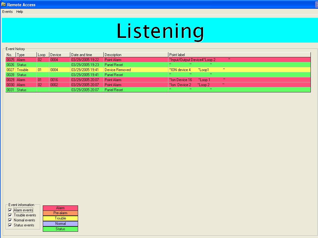
39 5.0 Remote Access The Evax Fire Solutions Programmer allows you to get events from the fire alarm control panel immediately when they occur. You can browse through 100 recent events and see where, when and why they occurred. Each event type has a unique color to distinguish between alarms (red), pre-alarms (orange), trouble (yellow) and status (green). The Evax Fire Solutions Programmer enables customization of the online event reception by filtering unwanted event types. To activate online events reception: In the Evax Fire Solutions Programmer main window, click Remote Access. The Remote Access window is displayed choose either Single Panel for a local panel or Multi Panel for the Network Remote Access The Remote Access window enables you to: Receive events online Print recent events Page 38 of 44

40 Page 39 of 44

41 6.0 Viewing point Discovery features: Discovery detectors use a digital communication protocol, which allows communication in three different modes: Normal, Read and Write Discovery features include reading/writing information stored in the non-volatile memory of the detector. To activate Discovery features: 1. Click the Discovery features from the Point menu. The Discovery features window is displayed: The Discovery features window enables you to: Get point type Get manufacture date Get approval data Get drift data Rapid update Set LED behavior Discovery test Page 40 of 44
42 6.1 Get point type Discovery devices include Ionisation Smoke Detector Optical Smoke Detector Heat Detector Multisensor Detector Carbon Monoxide Detector Manual Call Point To distinguish between each, Discovery devices have a unique device identification code called Point type saved in its non-volatile memory To get the point type: Click the Get point type button. The result will appear next to the button. 6.3 Get manufacture date: Every Discovery device includes its manufacture date in the non-volatile memory. 6.4 To get the manufacture date: Click the Get MFR date button. The result will appear next to the button. Get approval data: Every Discovery device includes its approval data (UL, EN54 etc) in the non-volatile memory. 6.5 To get the approval data: Click the Get approval data button. The result will appear next to the button. Page 41 of 44
43 6.6 Get drift data: All Discovery smoke detectors include compensation for sensor drift as part of the internal signal-processing algorithm. The algorithm will compensate for changes in sensor output caused, for example, by dust in the chamber. The compensation level is stored in the detector s memory as a single value between 0 and To get the drift data: Click the Get drift data button. The result will appear next to the button. 7.0 Rapid update: Rapidly re-updates the drift sensitivity of the device when you change out a detector or move a detector to a new location. You must do a Rapid update when you change out a device or clean a device. 7.1 To run the rapid update: Click the Rapid update button. The result will appear next to the button. 7.2 Set LED behavior: All Discovery detectors have two integral LED indicators, which can be illuminated at any time by the control panel to indicate devices in alarm. In addition to this mode of operation it is possible to enable a flashing LED mode by writing to one of the memory locations. In this mode the LEDs will flash each time the device is polled. 7.3 To set the LED behavior: 1. Check/uncheck Blink when polling. 2. Click the Set LED behavior button. A message box will confirm the result. Page 42 of 44


44 8.0 Discovery test: Discovery devices include an internal test procedure. To run the Discovery test: 1. Click the Discovery test button Page 43 of 44
Operation Manual Fighter ProVision Software. Version: 0.0 Revision: 1
 Operation Manual Fighter ProVision Software Version: 0.0 Revision: 1 TABLE OF CONTENTS 1. Introduction 5 2. Software Installation 5 3. PC Users 6 3.1 Introduction 6 3.2 Default Code 6 3.3 Edit PC User
D8024, D9024, D10024 Analog Fire Alarm Control Panels Programming Guide
 System Reset Trou ble Silence Ala rm Silence Manual Ala rm ENTER NO YES Letters Numb ers Keyword Radionics System Reset Trouble Silence Alarm Silence Manual Alarm ENTER NO YES Le ters Numbers Keyw ord
Halton SAFE / 7.14 user guide and installation instructions
 Halton SAFE / 7.14 user guide and installation instructions VERIFIED SOLUTIONS BY H A LTO N Enabling Wellbeing Table of contents 1 System description 3 2 User Accounts 4 3 Main menu 7 3.1 Main menu - Change
Section 9 System Operation
 Section 9 System Operation Operation of the control panel is simple. Menus guide you step-by-step through operations. This section of the manual is an overview of the operation menus. Please read this
AFP-300/400 OPERATORS MANUAL INTELLIGENT FIRE DETECTION AND ALARM SYSTEM SOFTWARE VERSION 2.2 REVISION AUS 3
 OPERATORS MANUAL AFP-300/400 INTELLIGENT FIRE DETECTION AND ALARM SYSTEM SOFTWARE VERSION 2.2 REVISION AUS 3 NSW (Head Office) 7 Columbia Court Norwest Business Park Baulkham Hills NSW 2153 Ph: (02) 9899-4155
Section 8 System Operation
 Section 8 System Operation Operation of the control panel is simple. Menus guide you step-by-step through operations. This section of the manual is an overview of the operation menus. Please read this
ViewMatrix. Software for Online Monitoring & Control of Matrix2000 Conventional Fire Alarm Panels. Version: 2.0 Revision: 0.1
 ViewMatrix Software for Online Monitoring & Control of Matrix2000 Conventional Fire Alarm Panels Version: 2.0 Revision: 0.1 CONTENTS 1. Introduction...3 2. Keyboard...5 2.1 POWER indication - Normal Operation...5
CSP-204 CSP-208 CSP-104 CSP-108
 Fire Alarm Control Panel CSP-204 CSP-208 CSP-104 CSP-108 Operation manual Firmware version 1.1 csp-x_o_en 06/15 SATEL sp. z o.o. ul. Budowlanych 66 80-298 Gdańsk POLAND tel. 58 320 94 00 www.satel.eu CONTENTS
Configuration and Operation Manual for the Unipos
 AxxonSoft Configuration and Operation Manual for the Unipos Integration Module Version 1.1 Moscow 2010 Contents CONTENTS... 2 1 LIST OF TERMS... 4 2 INTRODUCTION... 6 2.1 Document purpose... 6 2.2 Purpose
DATA SHEET CHEETAH XI 50 INTELLIGENT SUPPRESSION CONTROL SYSTEM DESCRIPTION APPROVALS: SYSTEM OPERATION. Form No. D
 DATA SHEET CHEETAH XI 50 INTELLIGENT SUPPRESSION CONTROL SYSTEM DESCRIPTION Fike s Cheetah Xi 50 (P/N 10-071) is a state-of-the-art true intelligent digital peer-to-peer modular suppression control system.
SCAN200E USER S MANUAL
 SCAN200E USER S MANUAL Code No. 2071 1052 rev. 1.4 Code No. 2071 1052 Rev. 1.4 Page 2/16 SCAN200E User s Manual Foreword This manual is for SCAN200E Controller running software version 2.03 or later. We
4010 Fire Alarm PC Programmer Installation and Programming Instructions
 4010 Fire Alarm PC Programmer Installation and Programming Instructions 574-187 Rev. C Copyright and Trademarks Copyright Simplex Time Recorder Co., 2000. All rights reserved. Printed in the United States
Testing the System. Battery Test. Dialer Test. Fire Drill Test (Code + [#] + 69) One-Man Fire Walk-Test (Code + [#] + 68)
![Testing the System. Battery Test. Dialer Test. Fire Drill Test (Code + [#] + 69) One-Man Fire Walk-Test (Code + [#] + 68)](/thumbs/79/79864325.jpg "Testing the System. Battery Test. Dialer Test. Fire Drill Test (Code + [#] + 69) One-Man Fire Walk-Test (Code + [#] + 68)") F A 1 7 0 0 c Testing the System Battery Test When AC power is present, the FA1700C runs a brief battery test every 60 seconds to determine if there is a battery connected, and runs an extended battery
F A 1 7 0 0 c Testing the System Battery Test When AC power is present, the FA1700C runs a brief battery test every 60 seconds to determine if there is a battery connected, and runs an extended battery
DATA SHEET CYBERCAT 254 INTELLIGENT FIRE ALARM CONTROL SYSTEM DESCRIPTION APPROVALS: SYSTEM OPERATION. Form No. D
 DATA SHEET CYBERCAT 254 INTELLIGENT FIRE ALARM CONTROL SYSTEM DESCRIPTION Fike s CyberCat 254 (P/N 10-066) is a state-of-the-art true intelligent digital peer-to-peer modular fire alarm control system.
TX7004. Intelligent Addressable Fire Alarm Control Panel Installation and Operation Manual. TANDA UK Technology Copyright 2015, All right reserved.
 TX7004 Intelligent Addressable Fire Alarm Control Panel Installation and Operation Manual Technology Copyright 2015, All right reserved. Product Safety To prevent severe injury and loss of life or property,
Fire Operator Workstation (Fire OWS) User s Guide
 User s Guide") Fire Operator Workstation (Fire OWS) User s Guide 1-1 Fire Operator Workstation (Fire OWS) User s Guide Introduction This user s guide details the components, capabilities, and operation procedures of
Fire Operator Workstation (Fire OWS) User s Guide 1-1 Fire Operator Workstation (Fire OWS) User s Guide Introduction This user s guide details the components, capabilities, and operation procedures of
DS9400 Series. Release Notes for Firmware V2.07. Fire Alarm Control Panel
 DS9400 Series EN Release Notes for Firmware V2.07 Fire Alarm Control Panel DS9400 Series Release Notes for Firmware V2.07 Trademarks Trademarks Gentex is a trademark of Gentex Corporation, Fire Protection
Replaceable LED modules. Sleep or unattended mode. Auto-silence and auto-acknowledge
 Replaceable LED modules 11 Alarm Sequences as per ISA-18.1 standard Each channel/window fully field programmable RS232 or RS485 MODBUS-RTU communication Repeat relay for each window and multifunction relays
MODUL-R FIRE ALARM CONTROL PANELS. MR-2900/MR-2920 Addressable Fire Alarm Control Panels MEA. Features. Description
 MODUL-R FIRE ALARM CONTROL PANELS MR-2900/MR-2920 Addressable Fire Alarm Control Panels Description MR-2900 Fire Alarm Control Panel The MR-2900 fire alarm system control unit is the heart of a sophisticated
Instruction manual MTL process alarm equipment. October 2016 CSM 725B rev 2 MTL RTK 725B. Configuration Software Manual
 Instruction manual MTL process alarm equipment October 2016 CSM 725B rev 2 MTL RTK 725B Configuration Software Manual SECTION 1 - INTRODUCTION... 5 Basic Requirements... 5 SECTION 2 - SOFTWARE INSTALLATION...
Section 4: Operating Instructions
 Section 4: Operating Instructions 4.1 Panel Control Buttons 4.1.1 Acknowledge/Step The first press of the Acknowledge/Step key silences the piezo sounder, changes flashing LEDs to steady and also changes
E N G L I S H FIRE ALARM ASPIRATION SENSING TECHNOLOGY QUICK INSTALLATION GUIDE STAND-ALONE FAAST LT MODELS FL0111E FL0112E FL0122E. 367 mm.
 E N G L I S H FIRE ALARM ASPIRATION SENSING TECHNOLOGY QUICK INSTALLATION GUIDE STAND-ALONE FAAST LT MODELS FL0E FL0E FL0E mm mm 0 mm DESCRIPTION The LT FL0 Series is part of the Fire Alarm Aspiration
Intelligent Security & Fire Ltd
 Product Data Sheet Mx-4000 Series User Manual MX-4100, MX-4200, MX-4400, Mx-4400/LE & Mx-4800 Fire Alarm Control Panels The operation and functions described in the manual are available from Software Versions
Intelligent Single Loop Fire Alarm Control Panel
 Intelligent Single Loop Fire Alarm Control Panel The CAX-CTL-1L Intelligent Single Loop Fire Alarm Control Panel is a member of the industry leading Axis AX Series Intelligent Fre Alarm Control Panels
FCD-wire Contents. List of Figures
 FCD-wire Contents FCD-X21 Configuration 1 Introduction... 1 2 Opening the FCD Application... 1 3 FCD Window... 2 4 FCD LEDs... 3 5 Configuration Operations... 4 FCD Info...4 FCD System Info...5 FCD Interface
user manual Document No , Revision 03 November 2015
 user manual Document No. 996-202-600-3, Revision 03 November 2015 Contents 1 Introduction...1 1.1 Notice...1 1.2 Models...1 2 User Control Levels...2 2.1 Level Definition...2 2.2 User Passwords...2 3 Controls
Addressable Fire Alarm Control Panel
 PRODUCT SPECIFICATION XR2400F Addressable FACP Addressable Fire Alarm Control Panel Description The DMP XR2400F Addressable Fire Alarm Control Panel is an expandable Fire Alarm Control with built-in DACT
Control Panel. 1.0 GENERAL SCOPE OF WORK Introduction... 2
 Architectural & Engineering Specifications Control Panel 1.0 GENERAL... 2 1.1 SCOPE OF WORK... 2 1.1.1 Introduction... 2 1.2 GENERAL CONDITIONS... 2 1.2.1 After-Sales Support... 2 1.2.2 Quality assurance...
RC-112 Two Speed Heat Pump 3 Stage Heat / 2 Stage Cool With Energy Efficient Control
 O M N I S T A T ELECTRONIC COMMUNICATING THERMOSTAT Installation Manual RC-112 Two Speed Heat Pump 3 Stage Heat / 2 Stage Cool With Energy Efficient Control Document Number 13I00-5 November, 1997 CONTENTS
Software Release M2.7 Summary for the Notifier AM2020/AFP1010 Fire / Security Control Panels, Including NOTI FIRE NET and Peripherals
 12 Clintonville Road Northford, CT 0642-1610 203-484-161 FAX: 203-484-118 Software Release M2. Summary for the Notifier AM2020/AFP1010 Fire / Security Control Panels, Including NOTI FIRE NET and Peripherals
The ID51 & ID52 can be upgraded to 2 loops without the need to change back box. FEATURES. Intelligent Features
 990-052, Issue 6 20 March 2006 ID50 Series Single Loop Intelligent Fire Alarm Panels Section: Intelligent Fire Alarm Panels GENERAL The NOTIFIER ID50 series single loop intelligent fire alarm panels, has
ION Meter Alerts TECHNICAL NOTE NOVEMBER In This Document
 70072-0125-01 TECHNICAL NOTE NOVEMBER 2006 ION Meter Alerts A PowerLogic ION meter can send alerts to indicate a user specified power system condition such as a power quality problem (including surges,
RESET + Password Enter (During Auto Speed Procedure) Maintenance Timeout or after TEST + RESET + DISABLE (No Need for Device to Initialize)
 Maintenance Timeout or after TEST + RESET + DISABLE (No Need for Device to Initialize)") FAAST LT FIRE ALARM ASPIRATION SENSING TECHNOLOGY ADVANCED SET-UP AND CONTROL GUIDE CONTENTS Introduction....1 The FAAST LT Functional State Diagram....1 Password Procedure (to enter Maintenance Mode)
FAAST LT FIRE ALARM ASPIRATION SENSING TECHNOLOGY ADVANCED SET-UP AND CONTROL GUIDE CONTENTS Introduction....1 The FAAST LT Functional State Diagram....1 Password Procedure (to enter Maintenance Mode)
CHEETAH XI INTELLIGENT SUPPRESSION CONTROL SYSTEM
 CHEETAH XI INTELLIGENT SUPPRESSION CONTROL SYSTEM DESCRIPTION Fike s Cheetah Xi (P/N 10-068) is a state-of-the-art true intelligent digital peer-topeer modular suppression control system. It is ideal for
Operating instructions SENTRI4 Control panel based Fire detection and alarm system
 1 2 3 4 5 6 7 8 9 10 11 12 13 14 15 16 17 18 19 20 21 22 23 24 25 26 27 28 29 30 30 32 Zones Healthy 15:45 Fault Power Fault System Fault SenTRI 4 Fire System Designed to EN54 Pt 2 & 4 Operating instructions
3D_ISS. Integrated Software System. User Guide Manual
 3D Digital Design & Development LTD 58/60 Edward Road Tribec House New Barnet EN4 8AZ 020 8440 7060 3D_ISS Integrated Software System User Guide Manual Copyright 2014 3D Digital Design and Development
M3092 Programmer. User s Manual. M3096B-33 E Copyright 2017 SELCO
 User s Manual Copyright 2017 SELCO SELCO Betonvej 11 - DK-4000 Roskilde Denmark Phone: 45 7026 1122 - Fax: 45 7026 2522 e-mail: selco@selco.com www.selco.com Table of contents 1 INTRODUCTION...4 2 SOFTWARE
ZX1e ZX2e ZX5e. Document No Issue 01 user manual
 ZX1e ZX2e ZX5e Document No. 996-130 Issue 01 user manual MORLEY-IAS ZX2E/ZX5E Fire Alarm Control Panels Table of Contents 1 INTRODUCTION... 4 1.1 NOTICE... 4 1.2 WARNINGS AND CAUTIONS... 4 1.3 NATIONAL
E N G L I S H FIRE ALARM ASPIRATION SENSING TECHNOLOGY QUICK INSTALLATION GUIDE ADDRESSABLE FAAST LT MODELS MI-FL2011EI, MI-FL2012EI AND MI-FL2022EI
 E N G L I S H FIRE ASPIRATION SENSING TECHNOLOGY QUICK INSTALLATION GUIDE ADDRESSABLE FAAST LT MODELS MI-FL0EI, MI-FL0EI AND MI-FL0EI mm mm 0 mm DESCRIPTION The LT MI-FL0 Series is part of the Fire Alarm
False Alarm Management
 False Alarm Management This document is intended only for fire system professionals who are already experienced in the selection and positioning of fire detectors. Whenever you apply any False Alarm Management
FMR Installation Instructions. Addressable Fire System Controller
 FMR-7033 EN Installation Instructions Addressable Fire System Controller EN 2 FMR-7033 Installation Instructions Contents Contents Contents...2 1.0 Introduction...3 2.0 Description...3 3.0 Device Mounting...3
PEGAsys. Multi-Loop Intelligent Suppression Control System FEATURES DESCRIPTION. Effective: March 2007 K
 PEGAsys Multi-Loop Intelligent Suppression Control System A UTC Fire & Security Company Effective: March 2007 K-76-028 FEATURES UL Listed CSFM Approved MEA Approved Peer-to-Peer Networking (to 32 nodes)
Sentient. Downloader Manual D4854
 Sentient Downloader Manual D4854 Dycon Ltd Tel: +44 (0)1443 471 060 Fax: +44 (0)1443 479 374 Cwm Cynon Business Park Mountain Ash CF45 4ER - UK www.dyconsecurity.com sales@dyconsecurity.com TABLE OF CONTENTS
Intelligent 2 & 4 Loop Fire Alarm Control Panels
 Intelligent 2 & 4 Loop Fire Alarm Control Panels Advanced has combined the latest technology with many years of fire experience, to create the Axis AX Series Intelligent Fire Alarm Control Panels. The
PS-Tools. User s Guide for the 50 Pt Addr Panel
 PS-Tools User s Guide for the 50 Pt Addr Panel Fire Alarm System Limitations While a fire alarm system may lower insurance rates, it is not a substitute for fire insurance! An automatic fire alarm system
ModSync Sequencing System Installation & Operation Manual. For use with Fulton Steam Boilers.
 ModSync Sequencing System Installation & Operation Manual For use with Fulton Steam Boilers. Revision 3.0 8/21/2008 - 2 - Table of Contents Introduction Page 4 Features Page 4 Sequence of Operation Page
Fire detection and alarm system Operating instructions
 Fire detection and alarm system Operating instructions Operating instructions Table of Contents User responsibility - - - - - - - - - - - - 4 Daily - - - - - - - - - - - - - - - - - - - 4 Weekly - - -
Fire System Objects. Introduction Page *3. Engineering *17. Data Base Generation *43
 Metasys etwork Technical Manual 636 Objects Section Technical Bulletin Issue Date 696 Fire System Objects Introduction Page *3 Description *3 Purpose *5 Capabilities *7 Functional Diagram *1 Operator Interface
HERCULES 6 GRAPHICS SYSTEM
 HERCULES 6 GRAPHICS SYSTEM USER MANUAL Protec Fire Detection PLC, Protec House, Churchill Way, Nelson, Lancashire, BB9 6RT. Telephone: +44 (0) 1282 717171 Fax: +44 (0) 1282 717273 Web: www.protec.co.uk
AIR-Intelligence Remote Configuration Software
 P/N 33-308100-004 September 2009 AIR-Intelligence Remote Configuration Software User s Guide FOREWORD Note: This Manual, P/N 33-308100-004, is to be used by qualified and factory-trained personnel, knowledgeable
Owner s Manual. Part Number 33CS250-RC
 CONTENTS Page GENERAL... 1 CONFIGURATION... 1-4 Transmitter Display... 1 Transmitter Indicator... 1 Transmitter Front Panel Buttons... 1 Set Clock... 2 Programming Thermostat Schedules... 3 OPERATION...5
Control/Communicator
 Architectural & Engineering Specifications Control/Communicator 1.0 GENERAL... 2 1.1 SCOPE OF WORK... 2 1.1.1 Introduction... 2 1.2 GENERAL CONDITIONS... 2 1.2.1 After-Sales Support... 2 1.2.2 Quality
FIRE DETECTION SYSTEM SPECIFICATION FOR MODEL XR200
 FIRE DETECTION SYSTEM SPECIFICATION FOR MODEL XR200 1.0 General 1.1 Manufacturer Manufacturer of the Fire Alarm Control Panel (FACP) equipment shall be: Digital Monitoring Products, Incorporated 2500 N.
2) This manual covers Fire and General Alarm systems. The differences are described in the appropriate sections.
 This manual covers Fire and General Alarm systems. The differences are described in the appropriate sections.") ISSUES ISSUE DATE RELEASED DETAILS OF CHANGE AUTHOR 4 Rev 2 September 2004 Changes for 4000 series. DB 4 Rev 3 April 2005 Screen shots updated and other minor changes K.Z. 4 Rev 4 September 2006 4 Rev
ISSUES ISSUE DATE RELEASED DETAILS OF CHANGE AUTHOR 4 Rev 2 September 2004 Changes for 4000 series. DB 4 Rev 3 April 2005 Screen shots updated and other minor changes K.Z. 4 Rev 4 September 2006 4 Rev
C&K Software What s New. Commander II Version 3.0 Monitor II Version 3.0 Satellite II Version 1.0
 C&K Software What s New Commander II Version 3.0 Monitor II Version 3.0 Satellite II Version 1.0 C&K Software PC-based receiver with monitoring features Windows-based Remote programming software (Commander
DS7400Xi Addressable Control/ Communicator
 DS7400Xi Addressable Control/ Communicator DS7400Xi DS7400Xi-EXP 110VAC operation 220VAC operation Remotely Programmable WDSRP (Windows Detection Systems Remote Programming Software), allows the systems
Security System. User s Guide for the Text Command Center
 User s Guide for the Text Command Center MY ALARM COMPANY IS: CALL BEFORE TEST: THIS SECURITY SYSTEM IS CONNECTED TO TELEPHONE NUMBER: THE SECURITY CONTROL PANEL IS CONNECTED TO THE PHONE JACK LOCATED:
Tempered Water Logic Control OPERATION l TROUBLE SHOOTING
 Tempered Water Logic Control OPERATION l TROUBLE SHOOTING English For MPE Multiple Chiller Units Control Panel TEMPERED WATER SYSTEMS L-2199 Rev. 20080223 Revision: L-2199 20101104 *** IMPORTANT NOTICE
Simplex Panel Interface Guide
 Simplex Panel Interface Guide February 2016 SATEON Software Integrations Simplex Panel Interface Guide Issue 1.0, released February 2016 Disclaimer Copyright 2016, Grosvenor Technology. All rights reserved.
Summit 3208GLD USER MANUAL. Electronics Line
 Summit 3208GLD USER MANUAL Electronics Line Table of Contents 1: Introduction... 2 2: Overview... 3 3: Keypad Functions... 4 3.1: Keypads... 4 3.2: 3108 LCD Keypad Layout... 4 4: Basic System Operation...
TX7004. Intelligent Addressable Fire Alarm Control Panel Installation and Operation Manual. TANDA UK Technology Copyright 2015, All right reserved.
 TX7004 Intelligent Addressable Fire Alarm Control Panel Installation and Operation Manual Technology Copyright 2015, All right reserved. Product Safety To prevent severe injury and loss of life or property,
THE EVOLUTION OF CONTROL APP & CLOUD PORTAL
 THE EVOLUTION OF CONTROL APP & CLOUD PORTAL APP MAIN APP FUNCTIONS EMERGENCY Facilitates the work of installers and company maintenance operators. Allows control of the functions of all lights of the system.
ZXe INTELLIGENT MULTI PROTOCOL FIRE ALARM CONTROL PANEL
 ZXe INTELLIGENT MULTI PROTOCOL FIRE ALARM CONTROL PANEL PRODUCT Specification FEATURES Designed To Meet The Requirements Of EN54 Expandable From 1 To 5 Loops As Standard A Variety Of Networking Options
Security System. User Guide for the LED Command Center
 Security System User Guide for the LED Command Center National Security Systems Inc (800)457-1999 MY SECURITY COMPANY IS: CALL BEFORE TEST: THIS SECURITY SYSTEM IS CONNECTED TO TELEPHONE NUMBER: THE SECURITY
The EN54 Part 2 & 4 Fire System
 Scope of work: To design, supply, install and commission an Analogue Addressable Fire Alarm Control System in accordance with the details specified herein and in accordance with supplied drawings The EN54
FIRERAY 5000 range USER GUIDE
 FIRERAY 5000 range USER GUIDE 0044-003-04 IMPORTANT PLEASE NOTE: The beam path MUST be kept clear of obstructions at all times! Failure to comply may result in the Detector initiating a Fire or Fault signal.
Installation Manual. ATS Remote Annunciator Catalog 5350 DANGER WARNING D
 ASCO 5350 The ASCO 5350 ATS Remote Annunciator is listed under the Underwriter s Laboratories Standard UL-1008 for Automatic Transfer Switch accessories. This stand-alone device provides individual status
CONVENTIONAL FIRE ALARM CONTROL UNITS. MR-2300 SERIES Fire Alarm Control Units MEA
 CONVENTIONAL FIRE ALARM CONTROL UNITS MR-2300 SERIES Fire Alarm Control Units Description Secutron s MR-2300 Series fire alarm control panels consist of six and twelve zone models which are equipped with
USER'S GUIDE FA1220CV. 2-Partition Security System N7003-1V2 7/98
 USER'S GUIDE FA1220CV 2-Partition Security System N7003-1V2 7/98 SYSTEM OVERVIEW... 3 General... 3 A Partitioned System... 3 Zones... 3 Burglary Protection... 4 Fire Protection... 4 Alarms... 5 Emergency
USER MANUAL DexTempTM 1000 Temperature Monitor (P/N: IR-1001) DexTempTM 1000 USB Non-Contact Temperature Monitor. User Manual.
 DexTempTM 1000 USB Non-Contact Temperature Monitor. User Manual.") USER MANUAL DexTempTM 1000 Temperature Monitor (P/N: IR-1001) DexTempTM 1000 USB Non-Contact Temperature Monitor User Manual 8690 Rev B Update: 10/24/2013 1 Table of Contents 1 Introduction.. 3 2 Host
USER MANUAL DexTempTM 1000 Temperature Monitor (P/N: IR-1001) DexTempTM 1000 USB Non-Contact Temperature Monitor User Manual 8690 Rev B Update: 10/24/2013 1 Table of Contents 1 Introduction.. 3 2 Host
FIRE ALARM SYSTEM 1.1 GENERAL REQUIREMENTS
 VALOUR COMMUNITY CENTRE FIRE ALARM SYSTEM Section 28 00 00 GYMNASIUM ADDITION & RENOVATION Page 1 of 3 28 00 00 FIRE ALARM SYSTEM 1.1 GENERAL REQUIREMENTS 1.2 SCOPE 1. The specification covering the General
The CWSI System CALL WITH QUESTIONS. RELY ON OUR KNOWLEDGE. DEPEND ON OUR EXPERIENCE. (800)
") The CWSI System The CWSI wireless fire alarm product line offers system versatility like none other. Frequency Hopping Spread Spectrum Technology (FHSS), coupled with Bi-directional RF Communication, Repeater
The CWSI System The CWSI wireless fire alarm product line offers system versatility like none other. Frequency Hopping Spread Spectrum Technology (FHSS), coupled with Bi-directional RF Communication, Repeater
Operating instructions Vigilon panel and Network node Fire detection and alarm system
 Healthy 15:45 Fault Power Fault Vigilon Fire System GENT 2015 Designed to EN54 Pt 2 & 4 System Fault Operating instructions Vigilon panel and Network node Fire detection and alarm system Test Fire Fault/Dis
Interactive Fire Control Panel IFS7002 four signal loops Instruction Manual
 Interactive Fire Control Panel IFS7002 four signal loops Instruction Manual Revision 6/01.17 Contents 1. Introduction... 6 2. Terminology... 6 3. Function... 8 4. Technical data... 8 4.1. Physical configuration...
Section 5. Control Systems
 Section 5 There are several Kaleidescape options available for controlling a Premier system. Kaleidescape Remote Kaleidescape App for ipad Kaleidescape Child Remote Browser interface control panels A Premiere
MR-2602 Two Zone Fire Alarm Control Panel
 MR-2602 Two Zone Fire Alarm Control Panel Installation Manual Secutron LT-2015 Rev.3 July 2010 Table of Contents 1 Introduction 1.1 The MR-2602 Fire Alarm Control Unit... 11 1.1.1 General features...
WeatherLink for Alarm Output Addendum
 WeatherLink for Alarm Output Addendum Introduction This Streaming Data Logger is designed to provide an electrical interface between a Vantage Pro or Vantage Pro2 weather station console or Weather Envoy
RC-90 / RC-90B Single Stage Heat/Cool Thermostat for Zone Control Systems Installation Instructions
 RC-90 / RC-90B Single Stage Heat/Cool Thermostat for Zone Control Systems Installation Instructions DESCRIPTION The RC-90 is a precision digital thermostat designed for 24 VAC single stage heating and
Fire Control Panel FS5100
 Fire Control Panel FS5100 INSTRUCTION MANUAL Revision 6/02.11 Contents 1. Introduction... 5 2. Terminology... 5 3. Function... 7 4. Technical data... 7 4.1. Modules... 7 4.1.1. Type of modules... 7 4.1.2.
725B Configuration Software Manual
 725B Configuration Software Manual REV DATED DESCRIPTION AUTHOR APPROVED 0 09-03-10 First Issue P.Cartmell Page 1 of 80 SECTION 1 - SOFTWARE INSTALLATION... 5 725B ConfigurationSoftware Installation...
AL802ULADA. NAC Power Extender. Installation Guide. (See Application Guide for additional information) Rev
 Rev") AL802ULADA NAC Power Extender Installation Guide (See Application Guide for additional information) Rev. 031703 Overview: The Altronix AL802ULADA is an extremely cost effective 8 amp voltage regulated
AL802ULADA NAC Power Extender Installation Guide (See Application Guide for additional information) Rev. 031703 Overview: The Altronix AL802ULADA is an extremely cost effective 8 amp voltage regulated
All-In-One Wireless Security System V1.0. Model #: MG Reference and Installation Manual
 All-In-One Wireless Security System V1.0 Model #: MG-6060 Reference and Installation Manual Table of Contents Introduction... 3 About Magellan and this Manual... 3 Conventions... 3 Specifications... 3
GEMC-FW-SLC FIRE SIGNALING LINE CIRCUIT MODULE INSTALLATION INSTRUCTIONS
 333 Bayview Avenue Amityville, New York 11701 For Sales and Repairs, (800) 645-9445 For Technical Service, (800) 645-9440 Publicly traded on NASDAQ Symbol: NSSC GEMC-FW-SLC FIRE SIGNALING LINE CIRCUIT
ID50series. intelligent fire alarm panels
 ID50series intelligent fire alarm panels features LPCB approved to EN54 parts 2 and 4 One loop capacity (99 sensors and 99 modules) 16 fire zones, 16 non fire zones Supports NOTIFIER advanced range of
RC-2000 Thermostat Installation Instructions
 RC-2000 Thermostat Installation Instructions DESCRIPTION The RC-2000 is a precision digital thermostat designed for 24 VAC heating and cooling systems. The RC-2000 will support the following systems: Single
HS-5100, HS-5200, HS-5400 ANALOGUE ADDRESSABLE CONTROL PANELS. User Manual. Approved Document UI-ELAN-02 Revision 03
 HS-5100, HS-5200, HS-5400 ANALOGUE ADDRESSABLE CONTROL PANELS User Manual Approved Document UI-ELAN-02 Revision 03 This page is intentionally blank Page 2 of 42 Table of Contents 1 INTRODUCTION 5 1.1 Standards
Syncro AS. Analogue Addressable Fire Control Panel. User Manual
 Syncro AS Analogue Addressable Fire Control Panel User Manual Man-1100 Issue 02 Nov. 2008 Index Section Page 1. Introduction...3 2. Safety...3 3. Panel Controls...4 3.1 Access Level 1...4 3.2 Access Level
ZM2 OPERATING AND MAINTENANCE INSTRUCTIONS
 ZM2 OPERATING AND MAINTENANCE INSTRUCTIONS CONTENTS 1. System Overview 2. User responsibilities 3. First Line controls and indications 3.1 Logging on to the fire alarm system 3.2 Checking system status
Platform Services BACnet Alarm Management
 Description: Guide to understanding and setting up BACnet Alarms, visualizing real-time and historical BACnet alarms using AlarmWorX64 Viewer and logging them to SQL database using AlarmWorX64 Logger OS
Honeywell Total Connect Remote Services
 Honeywell Total Connect Remote Services Basic User Guide With Honeywell Total Connect Remote Services, you can stay connected and in control of your home or business whenever you want, wherever you are.
The supplier and installer of the system should be approved by the local civil defence authority.
 ANALOGUE ADDRESSABLE FIRE ALARM SYSTEM 1. Scope of Work The contractor shall supply, install, test and commission a modern Analogue Addressable Fire Detection and Alarm System of an approved manufacturer
Operator s Manual Part: InfoAlarm Product: 4100U, 4100ES Rev. B
 Operator s Manual Part: InfoAlarm Product: 4100U, 4100ES 579-685 Rev. B ii iii Cautions and Warnings Cautions and Warnings READ AND SAVE THESE INSTRUCTIONS- Follow the instructions in this installation
MR-2350/2351 Series Analog/Addressable Fire Alarm Panel
 MR-2350/2351 Series Analog/Addressable Fire Alarm Panel Programming Manual Secutron LT-1040SEC Rev. 1 January 2017 MR-2350/2351 Series Programming Manual Table of Contents System Configuration 3 Panel
IP & SMS Alarm Communicator
 Models: WGSMSC You deserve to feel safe, secure & protected IP & SMS Alarm Communicator Quick Start Guide Thank you for purchasing a Watchguard IP & SMS Alarm Communicator This Quick Start Guide covers
OVEN INDUSTRIES, INC.
 OVEN INDUSTRIES, INC. OPERATING MANUAL Model 5C7-252 TEMPERATURE CONTROLLER With PLC Inputs Introduction Thank you for purchasing our controller. The Model 5C7-252 is an exceptionally versatile unit and
CAN bus-based I/O module, CIO relays Mounting Terminals and wiring Commissioning, using the utility software
 INSTALLATION AND COMMISSIONING GUIDE CAN bus-based I/O module, CIO 208 8 relays Mounting Terminals and wiring Commissioning, using the utility software DEIF A/S Frisenborgvej 33 DK-7800 Skive Tel.: +45
RCS Residential Control Systems Inc.
 RCS Residential Control Systems Inc. Model TZ16 Z-Wave Communicating Thermostat with Rev P HVAC Control Unit INSTALLATION AND OPERATION MANUAL DCN: 141-00882 Rev 02 5/18/06 This manual applies to the following
All-In-One Wireless Security System V1.0. Model #: MG-6060
 All-In-One Wireless Security System V1.0 Model #: MG-6060 Reference and Installation Manual DRAFT Table of Contents Introduction... 5 About Magellan and this Manual... 5 Conventions... 5 Specifications...
PERMACONN PM1030 Includes DI300. Installation Manual
 PERMACONN PM1030 Includes DI300 Installation Manual Radio Data Comms Unit 5/20-30 Stubbs Street Silverwater NSW 2128 Telephone: 02 9352 1777 Facsimile: 02 9352 1700 Introduction The PERMACONN system provides
BURGLAR ALARM PANEL BS-468
 BURGLAR ALARM PANEL BS-468 Contents 1. Description... 3 2. Instructions for the user... 4 2.1Basic operations... 4 Complete system.... 4 Split system.... 4 2.2 Armed system indication... 5 2.3 Advanced