Davis Besse NPP Construction
|
|
|
- Kenneth Reynolds
- 5 years ago
- Views:
Transcription
1 Davis Besse NPP Construction Pushing Dirt and Digging Holes Actually started in 1969 below grade. When the AEC issued a Construction Permit (CP) above grade work could proceed. Below grade work was allowed without a CP with the requirement that if you bailed on the project the Site would be returned to As found condition. Planned Commercial NPP construction enjoyed a huge growth spurt in the 70s, encouraged by the optimistic load growth projections and the Atoms for Peace program. It was almost as if anyone who could write the check could buy a nuke. Orders for new Nuke Plants peaked in 1975 at ~210 projected plants. By 1978, 40% of these new plant orders had been cancelled. So it wasn t the TMI 2 Accident in 1979 that directly killed enthusiasm for NPPs. If you happened to find one for sale in the Sears and Roebuck Catalog, it came with an asterisk, Some Assembly Required. This slide show should help.
.")
2 The original Licensing Basis Document was the 4 volume Preliminary Safety Analysis Report (PSAR) shown here. You couldn t get an Operating License for the plant until this document had grown in width until it expanded to 17 volumes for the Final Safety Analysis Report (FSAR). Who da thunk it, just that extra paper could triple the cost of the Plant.
3
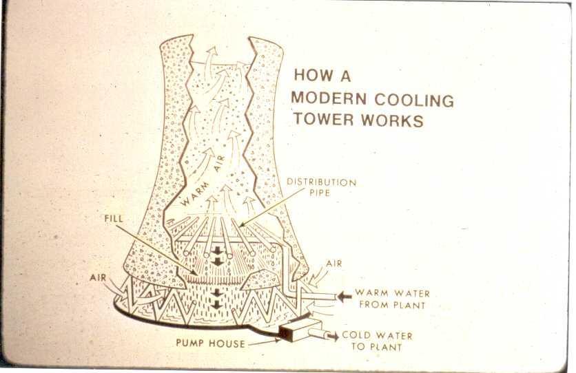
4 The Davis Besse Plant Cooling Tower was an optional decision by the Toledo Edison Company, after all the Plant was on the shore of Lake Erie. The Cooling Tower supplier was the Research-Cottrell Company. At the time we were the northern most location for operation of a Research- Cottrell Cooling Tower, so they didn t have a lot of experience operating a tower that far north with cold winters. The concern was as the tower operated on cold windy days ice would build up on the open space at the bottom provided for the cooling air inlet. This ice build up effectively blocked the cooling air inlet flow path, thus the Main Condenser Cooling Water Temperature could increase, affecting the Main Condenser vacuum and by that Plant Generator electrical output. To offset that possibility a de-icing spray header was installed at the top of the air inlet section to redirect some warm Cooling Water to melt the ice build up. But winters can get really cold on Lake Erie, so using the de-icing header could make more ice than the local ice supplier. We found out the best thing to do was basically leave it alone and let Mother Nature naturally self-regulate the ice build up. It never affected the Main Condenser vacuum to the point of affecting the plant load output.

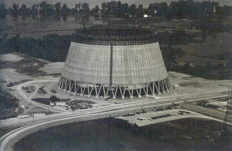
5 I started working for Toledo Edison in 1970, so I missed this initial construction work on the Cooling Tower foundation. But I did see most of it proceed, driving to work every day in Toledo.
6

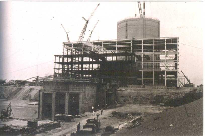
7 This is a view from the direction of the lake shore by the Intake Canal at about the eventual location of the Submarine Net. During construction the canal was open to the lake for large component delivery by barge. It would later be diked off, separated by an underwater concrete pipe extending a half mile into the lake and become our Ultimate Heat Sink. The lake end of the pipe was covered with a wooden crib, complete with an air bubbler system to keep the fish away. That idea didn t work so hot either as the fish liked the air bubbles, but you could always find the crib; it was where all the fishing boats were anchored. The plant was a self-contained city, having our own water, sewer, fire protection system, emergency electrical power, etc. Since we had a semi closed loop Cooling Tower for the Main Condenser cooling, this Intake Canal was the source of water for Auxiliary Cooling Water functions, tower makeup water to replace the tower vapor plume, etc. In this view the Containment Vessel Shield Building and Cooling Tower are complete. Construction of the Turbine Building is on going. The 2 large tanks in the Turbine Building are the Condensate Storage Tanks.

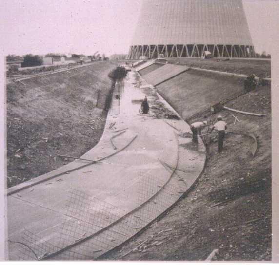
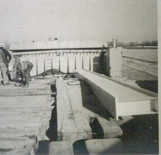
8 Construction of the concrete Cooling Tower return water canal near the Turbine Building end.
9

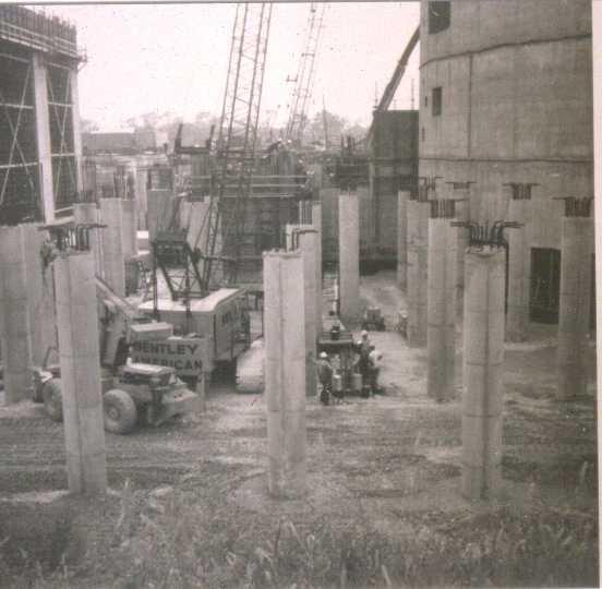
10 Turbine Building support column construction.
11
 with Circ Water pipes to the Cooling Tower, and at the lower left of the TB is the start of the Intake Screen House.")
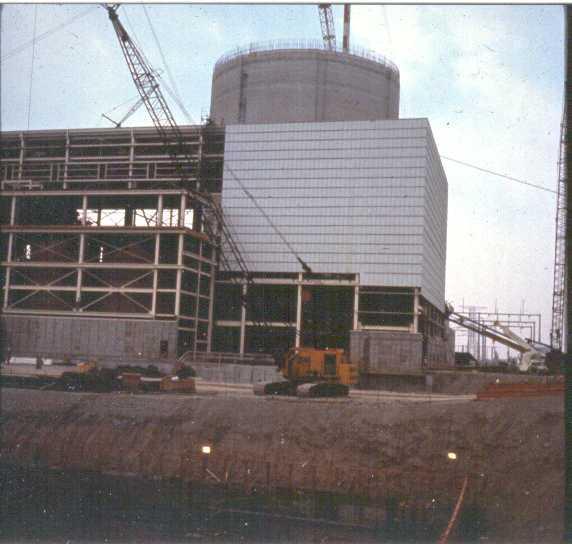
12 This plant is so old that color film was just experimental. The center structure is the Turbine Building (TB) with Circ Water pipes to the Cooling Tower, and at the lower left of the TB is the start of the Intake Screen House. The structure to the left center is the Spent Fuel Pool. The Containment Vessel Shield Building shows rows of holes that will become pipe and electrical penetrations. The large hole will become the Personnel Access Hatch, the one above a Main Steam Line penetration, and the right one the Containment Purge penetration.

13 Circ Water Pump House showing Circ Water Pump discharge piping.

14 Circ Pump Suction Piping and construction of the pump pedestals.

15 Not positive on this, either a sluice gate for the Intake Structure or the Circ Pump House.

16 But this guy probably knows is that you JD?

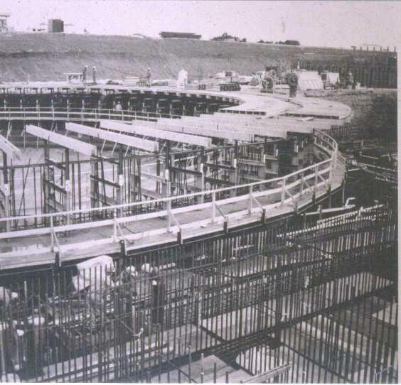
17 The water distribution area in side the Cooling Tower, about 50 off the ground, is called the Fill. These concrete beams hold up the Fill. Looks like some concrete beams will be involved in Let s do it over.

18 Installation of water distribution baffles in the Cooling Tower.

19 Water distribution pipes inside the Cooling Tower above the water distribution baffles below. Note the up-sidedown umbrellas below the pipes to spread the water flow.

20 Sub-grade work starting on the Containment Vessel and Shield Building.
21

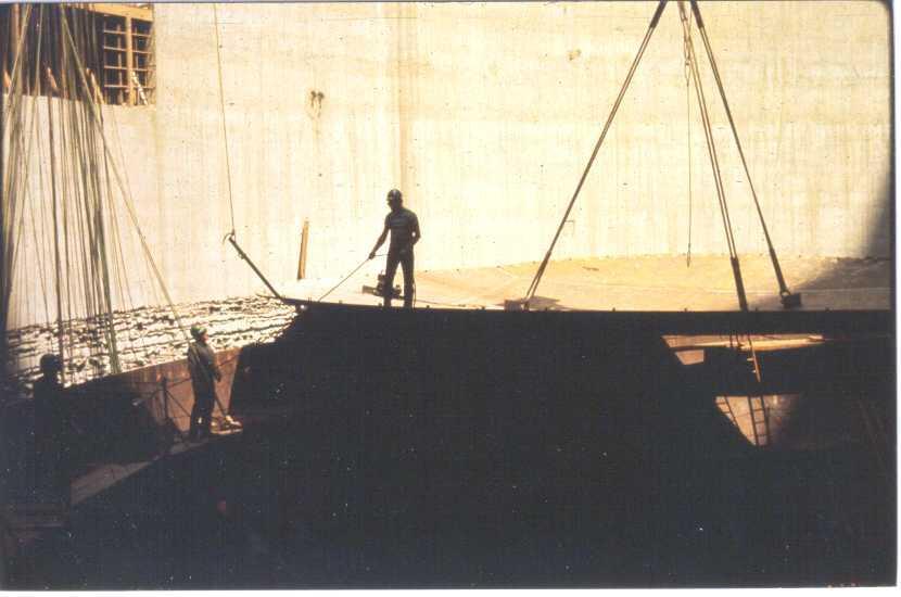
22 Work on the bottom of the 2 thick steel Containment Vessel container, the actual pressure boundary to atmosphere. The concrete Shield Building is a biological radiation shield and an external missile shield for the steel Containment Vessel.
23

24 Placing the bottom of the Containment Vessel, the manhole cover for the drain to China isn t installed yet (just kidding!).

25 Starting the rebar for the area directly under the Reactor Pressure Vessel. The circular rebar section will become the Containment Normal Sump.

26 The white box is the actual concrete sump where the Containment Sump Pumps will end up. You can see the rebar that will form the tunnel from the sump area to below the Reactor Vessel.

27 The concrete pit enclosing the Reactor Vessel is shaping up.
28

29 Containment, top still open with top steel pieces in the lay-down area. The building to the right is the Turbine Building with the Circ Pump House in its lower left corner.

30 Fuel Transfer Tubes with up-ender device shown. These are used to transfer fuel, under water for radiation shielding, between the Containment Refueling Canal and the Spent Fuel Pool in the Auxiliary Building.
31
32

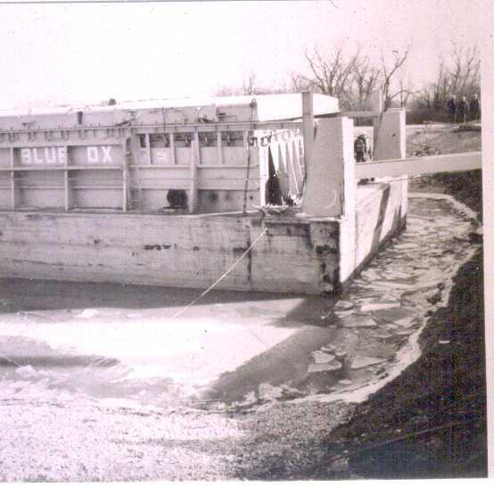
33 Barge and Tugboat delivering Circ Water pipes.

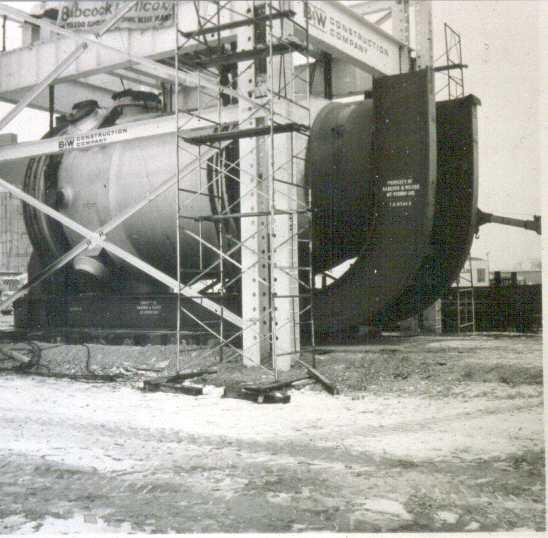
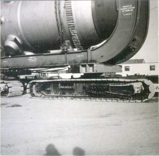
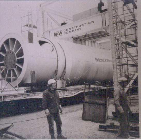
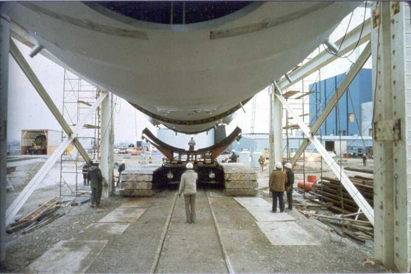
34 Hard to guess, but since it is on the super crawler, some heavy component shored up with timbers.
 nozzles are the offsets.")
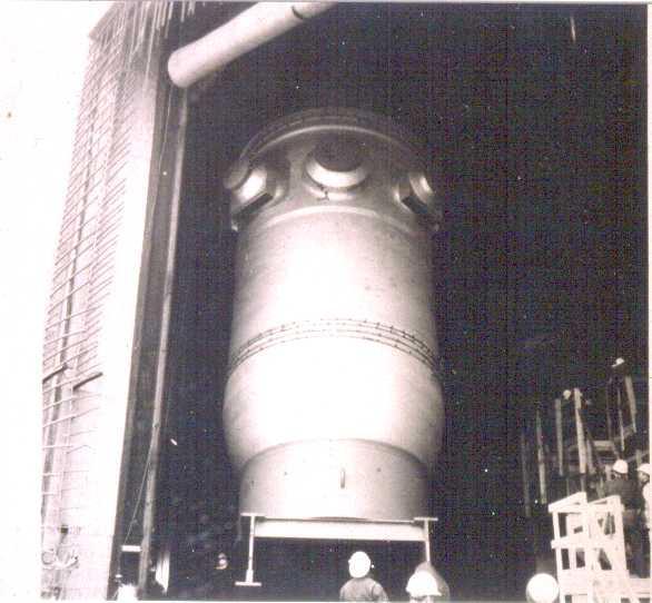
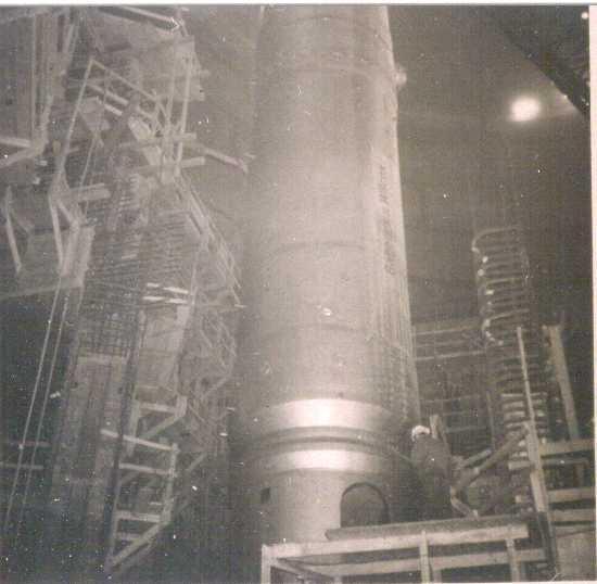
35 Reactor Pressure Vessel. The 2 Hot Leg (outlet) nozzles are at very top and bottom. Two of the 4 Cold Leg (inlet) nozzles are the offsets. The Core Flood Low Pressure Injection nozzle is the small one.
36
37
38

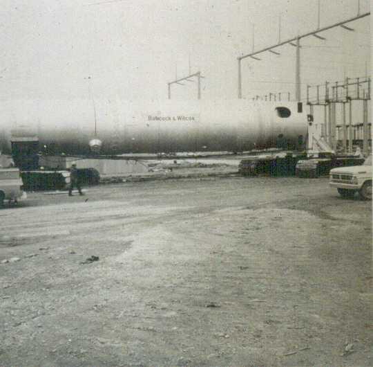
39 Hey, you got the crawler keys ; nope, thought you had m. Note the 345KV switchyard.

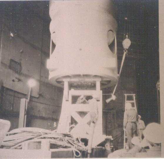
40 Into the Containment Vessel.

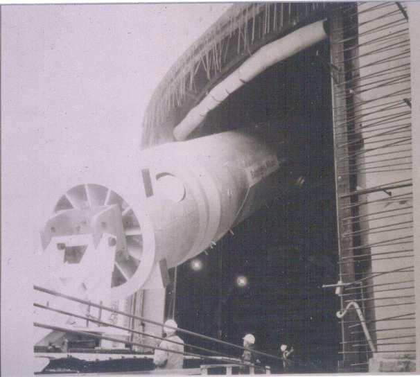
41 Positioning for Polar Crane lift.

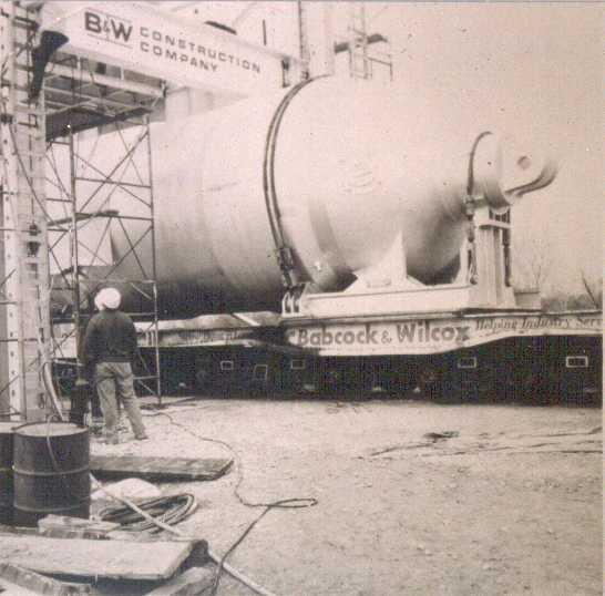
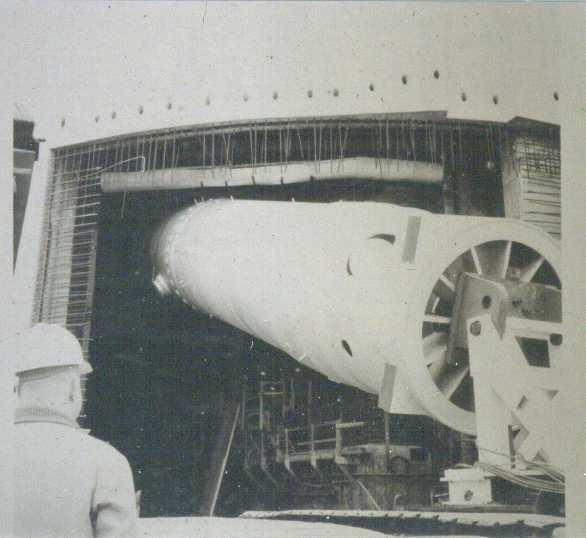
42 Upright, it pivots on its shipping cradle.
43

44 This is the concrete enclosure pit the Reactor Pressure Vessel will sit inside. They appear to be measuring the Hot Leg pipe outlet hole clearance. I think they re using a yardstick from Brinnon s Paint Supply; I still have mine.

45 Down through the Refueling Canal.

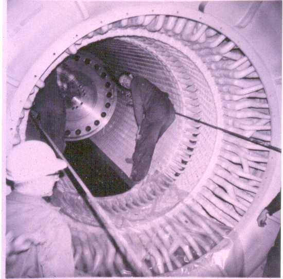
46 Once Through Steam Generator (SG). These were the longest lasting SGs in the US PWR industry, thanks to the efforts of Dave Briden, the original plant Chief Chemist. They made it forty years without replacement, until the 2014 refueling outage
47
48
49
50

51 Polar Crane Lift.
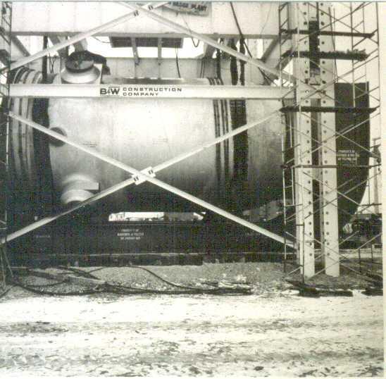
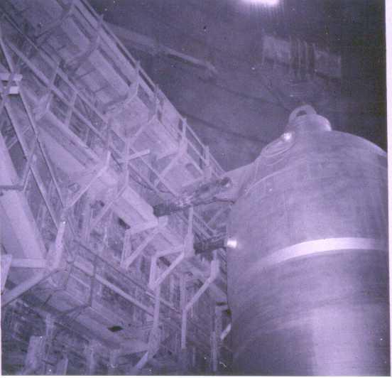
52
53
54
55

56 That s where it will sit
57
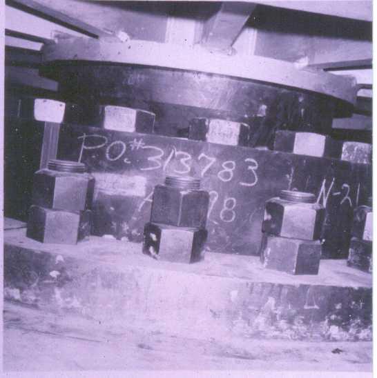
58 Top anchor attachments

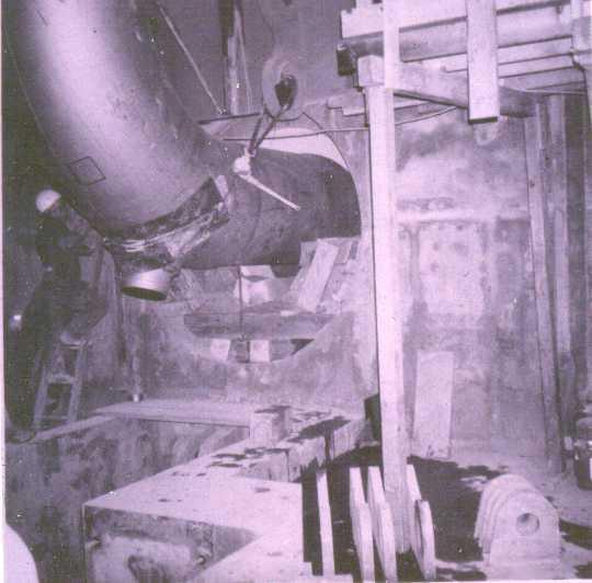
59 Lower end of SG showing the lower tube sheet access manhole. The small hand holes just above are for access to the internal movable orifice plate. The 80 Hot Leg pipe to the top of the SG is to the right. The smaller nozzle on the Hot Leg is the Decay Heat drop line to the Decay Heat Removal Pump Suction.
60

61 Heat Exchanger about to go through the Turbine Building Train Bay door.

62 Best guess is it is the Pressurizer about to go into the Containment Vessel.

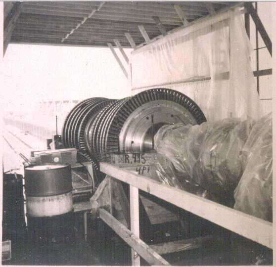
63 A Main Turbine Rotor Section
64
65

66 Intake Canal with Intake Structure Gantry Crane at upper left.

67 Construction of Intake Structure Screen House inlet bays. This work was done before the Intake Canal was flooded.
68

69 Access pits for pump suctions on the Plant side of the Intake Structure Traveling Screens (fish and debris strainers)

70 Service Water System pump suction lines in the Screen House. The gizmos are probably foot valves on the suction lines.

71 Not even a clue.
 for drawing a vacuum in the Main")
72 Mechanical Hogger (high capacity vacuum pump) for drawing a vacuum in the Main Condenser.

73 Booster Feed Pump end of a Main Feed Pump.

74 Reduction Gear, coupled a Main Feed Pump Turbine to the Main Feed Pump.

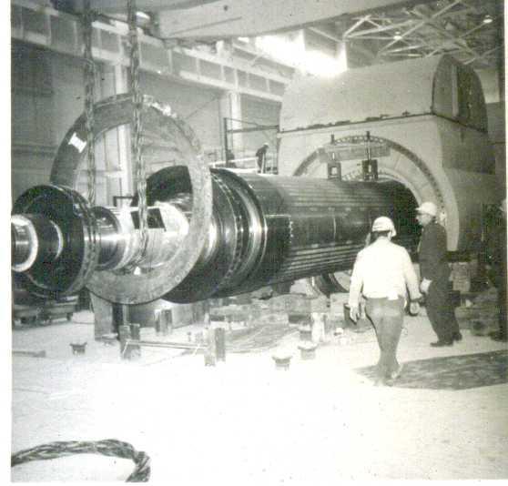
75 Main Generator Rotor lifted with the Turbine Building Crane.
76
77

78 Auxiliary Feed Pump Turbine Steam Exhaust. The white building is the Administration Office Building, proof that there was an Ivory Tower.
Speransa 2008: Round table: Nuclear and sustainable development Universitad Politecnica de Valencia \UPV - Passive safety systems -
 Universitad Politecnica de Valencia \UPV - Passive safety systems - complete+annex.doc 1 1.1 Definition of Passive Safety Systems...3 2. Passive safety systems for core decay heat removal....4 2.1 Pre-Pressurized
Development of Post-Accident Monitoring System for Severe Accidents
 Development of Post-Accident Monitoring System for Severe Accidents Chang-Hwoi Kim a, Sup Hur b, Kwang-Sub Son c, and Tong-Il Jang d a b c d Abstract: To cope with a severe accident such as Fukushima Nuclear
ANNEX V. AP600 & AP1000 Westinghouse Electric, USA
 ANNEX V. AP600 & AP1000 Westinghouse Electric, USA Reactor System Reactor Type Power (MW th) Passive Safety Systems CORE/PRIMARY: Advanced Passive PWR (AP600) and (AP100) Westinghouse Electric, USA PWR
MINIMUM TANK GAP. Greater of 3 or one-sixth of sum of adjacent tank diameters. one-half of sum of adjacent tank diameters 20
 Piping Layout Design Introduction The performance requirements of the equipment are developed by design teams which normally include members from the different departments such as process, engineering,
FUNDAMENTAL SAFETY OVERVIEW VOLUME 2: DESIGN AND SAFETY CHAPTER I: AUXILIARY SYSTEMS 3. CONTINUOUS VENTILATION OF THE CONTAINMENT (EVR [CCVS])
![FUNDAMENTAL SAFETY OVERVIEW VOLUME 2: DESIGN AND SAFETY CHAPTER I: AUXILIARY SYSTEMS 3. CONTINUOUS VENTILATION OF THE CONTAINMENT (EVR [CCVS])](/thumbs/89/101169886.jpg "FUNDAMENTAL SAFETY OVERVIEW VOLUME 2: DESIGN AND SAFETY CHAPTER I: AUXILIARY SYSTEMS 3. CONTINUOUS VENTILATION OF THE CONTAINMENT (EVR [CCVS])") PAGE : 1 / 7 3. CONTINUOUS VENTILATION OF THE CONTAINMENT (EVR [CCVS]) GENERAL DESIGN OF THE REACTOR BUILDING VENTILATION SYSTEM Access into the Reactor Building is permitted during operation between seven
PAGE : 1 / 7 3. CONTINUOUS VENTILATION OF THE CONTAINMENT (EVR [CCVS]) GENERAL DESIGN OF THE REACTOR BUILDING VENTILATION SYSTEM Access into the Reactor Building is permitted during operation between seven
CHAPTER 5 CONDENSER AND EVAPORATIVE COOLING TOWER
 CHAPTER 5 CONDENSER AND EVAPORATIVE COOLING TOWER 5.1. Condenser... 2 5.2. Evaporative Cooling Tower... 2 5.2.1. Major Components...3 Chapter 5-1 5.1. Condenser Condenser is a shell-and-tube heat exchanger.
INTRODUCTION TO SOLAR THERMAL POWER STATIONS We shall look at some of the different methods of supplying solar energy to the power stations.
 SOLAR THERMAL POWER PLANTS There are different types of solar thermal power stations where the energy from the sun is collected by an arrangement of mirrors. These rotate or tilt to follow the suns arcing
Catawba Nuclear Station Delay Coil Chemical Decon Projects
 Catawba Nuclear Station Delay Coil Chemical Decon Projects Catawba Nuclear Station Delay Coil Chemical Decon Projects Catawba Units 1 & 2 are four-loop Westinghouse PWRs located in York, SC which is located
FUNDAMENTAL SAFETY OVERVIEW VOLUME 2: DESIGN AND SAFETY CHAPTER I: AUXILIARY SYSTEMS 2. COMPONENT COOLING SYSTEM FOR THE NUCLEAR ISLAND (RRI [CCWS])
![FUNDAMENTAL SAFETY OVERVIEW VOLUME 2: DESIGN AND SAFETY CHAPTER I: AUXILIARY SYSTEMS 2. COMPONENT COOLING SYSTEM FOR THE NUCLEAR ISLAND (RRI [CCWS])](/thumbs/85/92566814.jpg "FUNDAMENTAL SAFETY OVERVIEW VOLUME 2: DESIGN AND SAFETY CHAPTER I: AUXILIARY SYSTEMS 2. COMPONENT COOLING SYSTEM FOR THE NUCLEAR ISLAND (RRI [CCWS])") PAGE : 1/ 17 2. COMPONENT COOLING SYSTEM FOR THE NUCLEAR ISLAND (RRI [CCWS]) 2.0. SAFETY REQUIREMENTS 2.0.1. Safety functions The RRI [CCWS] system contribution to the three fundamental safety functions
PAGE : 1/ 17 2. COMPONENT COOLING SYSTEM FOR THE NUCLEAR ISLAND (RRI [CCWS]) 2.0. SAFETY REQUIREMENTS 2.0.1. Safety functions The RRI [CCWS] system contribution to the three fundamental safety functions
Appendix B3 System/Component Cause Codes
 Appendix B3 System/Component Cause Codes NUCLEAR UNITS INDEX TO SYSTEM/COMPONENT CAUSE CODES (Unit Codes 200-299) Cause Code NUCLEAR REACTOR Ranges Page No. Core/Fuel 2010-2090 B-NU-3 Control Rods and
Chapter 11. Design of Other BOP
 Nuclear Systems Design Chapter 11. Design of Other BOP Prof. Hee Cheon NO 11.1 Condenser Design 11.1.1 Consider Performance Requirements Accepting heat rejected by steam cycle as final heat sink Maintaining
Series 300 VTB. Installation Instructions
 Series 300 VTB Installation Instructions Sizes 7 12 16 20 30 HP #2 Fuel Oil Gas (500 to 2500 BTU) Gas Light Oil Combination High Pressure Steam Sizes 7 thru 16 HP (125 PSI) Sizes 20 and 30 HP (150 PSI)
Water is supplied from the discharge of the Circulating Water System to a Distribution Basin, from which the Cooling Tower Pumps take a suction.
 Cooling Towers Functions Cooling Towers have one function: Remove heat from the water discharged from the condenser so that the water can be discharged to the river or recirculated and reused. Some power
Comanche Peak Nuclear Power Plant. Emergency Planning
 Comanche Peak Nuclear Power Plant Emergency Planning Comanche Peak Nuclear Power Plant Glen Rose, TX Two Unit Pressurized Water Reactors 1250 Megawatts Electrical per Unit Squaw Creek Reservoir Dam Unit
COOPERATIVE PATENT CLASSIFICATION
 CPC F COOPERATIVE PATENT CLASSIFICATION MECHANICAL ENGINEERING; LIGHTING; HEATING; WEAPONS; BLASTING (NOTE omitted) LIGHTING; HEATING F28 HEAT EXCHANGE IN GENERAL (NOTES omitted) F28D HEAT-EXCHANGE APPARATUS,
Application of Radioactive Particle Tracking (RPT) and Densitometry for Measuring Liquid Velocity Fields and Void Fraction in Convective Boiling Flows
 and Densitometry for Measuring Liquid Velocity Fields and Void Fraction in Convective Boiling Flows") ID: B01-04 Application of Radioactive Particle Tracking (RPT) and Densitometry for Measuring Liquid Velocity Fields and Void Fraction in Convective Boiling Flows Ashutosh Yadav 1, Harish Jagat Pant 2 and
ID: B01-04 Application of Radioactive Particle Tracking (RPT) and Densitometry for Measuring Liquid Velocity Fields and Void Fraction in Convective Boiling Flows Ashutosh Yadav 1, Harish Jagat Pant 2 and
MUST READ PRIOR TO CONSTRUCTION!
 MUST READ PRIOR TO CONSTRUCTION! IMPORTANT Fully read the installation manual prior to construction. Improper installation or failure to follow manufacturer s instructions, directions, illustrations and
Appendix B9 Geothermal Unit Cause Codes
 Appendix B9 Geothermal Unit Cause Codes GEOTHERMAL UNITS INDEX TO SYSTEM/COMPONENT CAUSE CODES (Unit Codes 800 899) Cause Code BOILER Ranges Page No. Boiler Piping System 0500-0620 B-GE-2 BALANCE OF PLANT
Borosilicate 3.3 Glass Pilot plants / Equipment
 Borosilicate 3.3 Glass Pilot plants / Equipment Pilot Plants / Assemblies are multi purpose units having flexibility of utility. These units have been standardized by incorporating all basic & essential
Technical Rescue Incidents
 Structural Collapse 1. You arrive to find an apartment building has collapsed. There are no reports of people missing or trapped. What are your initial actions as first responders at the awareness level?
ANNEX A-1 GEOTHERMAL UNITS INDEX TO SYSTEM/COMPONENT CAUSE CODES BOILER BALANCE OF PLANT STEAM TURBINE GENERATOR MISCELLANEOUS - GEOTHERMAL EXTERNAL
 ANNEX A-1 GEOTHERMAL UNITS INDEX TO SYSTEM/COMPONENT CAUSE CODES Boiler Piping System 0500-0620 Condensing System 3110-3199 Circulating Water Systems 3210-3285 Waste Water (zero discharge) 3290-3299 Condensate
Annex A-8 CONCENTRATED SOLAR POWER UNITS INDEX TO SYSTEM/COMPONENT CAUSE CODES
 Annex A-8 CONCENTRATED SOLAR POWER UNITS INDEX TO SYSTEM/COMPONENT CAUSE CODES SOLAR ENERGY GATHERING EQUIPMENT Solar Field 6500-6559 Thermal Storage 6570-6589 Operational Problems 6590-6599 STEAM TURBINE
What on Earth? Your Soil Health Explained
 00 What on Earth? Your Soil Health Explained 01 You could be forgiven for writing-off soil as just dirt, but if we didn t have soil we wouldn t have food to eat, or freshwater to drink. Even the paper
SANTA ROSA FIRE DEPARTMENT FIRE PREVENTION BUREAU PLAN REVIEW CHECKLIST
 July 1, 2010 SANTA ROSA FIRE DEPARTMENT FIRE PREVENTION BUREAU PLAN REVIEW CHECKLIST FIRE PUMP REVIEW Address: Permit #: Inspector: Date: Status: Inspector: Date: Status: A-Approved; AC-Approved w/comments;
I&C Upgradation and Modernization at CHASNUPP 1 & 2. Presented By: Waseem Uddin Farooqi PAEC, Pakistan
 I&C Upgradation and Modernization at CHASNUPP 1 & 2 Presented By: Waseem Uddin Farooqi PAEC, Pakistan Contents of Presentation Nuclear Power in Pakistan I&C Overview of CHASNUPP-1 & 2 (C-1 & C-2) I&C Upgradation
Installation and Operating Service Manual
 Installation and Operating Service Manual SPRAY-TYPE DEAERATOR Bryan Steam LLC, 783 N. Chili Avenue, Peru, IN 46970, Phone 765.473.6651, Fax 765.473.3074 www.bryanboilers.com Form 2141 Revision Date 5/1/2015
Lata Mishra Bhabha Atomic Research Centre, INDIA
 Lata Mishra Bhabha Atomic Research Centre, INDIA Outline of presentation Legal & Regulatory provisions / requirements Safety criteria & Safety objectives PIE s Safety & Seismic categorization Safety provisions
Seabrook Station Condenser Tube Leaks. Jim Johnson Seabrook Station FSRUG 2017
 Seabrook Station Condenser Tube Leaks Jim Johnson Seabrook Station FSRUG 2017 1 Seabrook Condenser Tube Leaks Seabrook Condenser and Circulating Water Design 4 Loop Westinghouse PWR, 1296 MWe Generation
PESIT-Bangalore South Campus
 USN PESIT Bangalore South Campus Hosur road, 1km before Electronic City, Bengaluru -560-100 Department of Mechanical Engineering INTERNAL ASSESSMENT TEST 2 Date : 03/04/2018 Max Marks : 50 Subject & Code
CONTENTS. B. System Design and Performance Requirements
 15625 Water Chillers This document provides design standards only, and is not intended for use, in whole or in part, as a specification. Do not copy this information verbatim in specifications or in notes
Design and Construction Standards SECTION PLUMBING EQUIPMENT
 SECTION 15450 PLUMBING EQUIPMENT PART 1 GENERAL 1.1 SECTION INCLUDES: A. Water heaters. B. Packaged water heating systems. C. Water storage tanks. D. Water softeners. E. Pumps. F. Circulators. 1.2 REFERENCES
Tray ST5. Tray Type Deaerator Pressurized.005 cc/liter. industrialsteam.com
 Tray ST5 Pressurized and Atmospheric Deaerators Tray Type Deaerator Pressurized.005 cc/liter COUNTER FLOW TRAY design provides guaranteed removal of all dissolved oxygen in excess of.005 cc/liter from
SECTION PLUMBING EQUIPMENT
 PART 1 GENERAL 1.1 SECTION INCLUDES A. Water heaters B. Packaged water heating systems C. Water storage tanks D. Water softeners E. Pumps F. Circulators 1.2 REFERENCES SECTION 22 30 00 PLUMBING EQUIPMENT
2016 Plumbing Supplemental Plan Review List
 Building Division 555 Santa Clara Street Vallejo CA 94590 707.648.4374 2016 Plumbing Supplemental Plan Review List POTABLE WATER SYSTEM P1. Specify which fixtures are for private use and which are for
Industrial. Solutions brands you trust. Product Overview
 Industrial Solutions brands you trust. Product Overview Industrial Pump Applications Crane & Systems design s the most efficient and economical pumps to serve the large diversity of industrial applications
Homeowners Manual. Thank you!
 Homeowners Manual Thank you! Thank you for purchasing a Blue Square Q360 In-Floor Cleaning System! With over 20 years of pool building and in-floor knowledge, this system was designed with you, our pool
Choosing the Right Pump
 Choosing the Right Pump Pumps are used to move fluid from one destination to another. They come in many different shapes, sizes, and operated by either electric motor, engine, by hand or solar power. They
Products for. Nuclear Power Applications
 Products for Nuclear Power Applications Caloritech electric heaters, heating elements and heating accessories are well-known in the industry for their quality, reliability, performance and versatility.
PRESSURE MOTIVE PUMP (PMP) APPLICATIONS
 APPLICATIONS") DRAINAGE of a SINGLE SOURCE of for a CLOSED LOOP SYSTEM PURPOSE: For removing condensate from below steam heat transfer equipment when a modulating valve is used for control and stall conditions will exist.
DRAINAGE of a SINGLE SOURCE of for a CLOSED LOOP SYSTEM PURPOSE: For removing condensate from below steam heat transfer equipment when a modulating valve is used for control and stall conditions will exist.
BASIL 6000 TUNNEL CAGE WASHER
 BASIL 6000 TUNNEL CAGE WASHER APPLICATION For thorough, efficient cleaning of cages, debris pans, bottles, feeder bowls, and miscellaneous items used in the care of laboratory animals. DESCRIPTION The
Unit Design Data. Nuclear (Voluntary Reporting) Utility name: Station name: Unit name: Location of unit (State):
 Utility name: Station name: Unit name: Location of unit (State):") Unit Design Data Nuclear (Voluntary Reporting) (Note: The NERC Board of Trustees approved the GADS Task Force Report (dated July 20, 2011) i, which states that design data collection outside the required
Unit Design Data Nuclear (Voluntary Reporting) (Note: The NERC Board of Trustees approved the GADS Task Force Report (dated July 20, 2011) i, which states that design data collection outside the required
Installation, Operation, and Maintenance Information
 Installation, Operation, and Maintenance Information Air Cooled Condensers 8-2016 Rev 0 Table of Contents General Safety Information 2 Inspection 2 Installation 2 6 Rigging and Assembly 2 Unit Location
Heat Pipe Applications Introduce
 Heat Pipe Applications Introduce Most suitable where: Low humidity level necessary Humidity control required Air reheated after cooling in traditional HVAC system Large quantities of ventilation air needed
Fire-Water Bowls Model 100
 Fire-Water Bowls Model 100 OWNER S MANUAL / OPERATING AND MAINTENANCE INSTRUCTIONS For your safety: If you smell gas: 1. Shut off gas to the appliance 2. Extinguish any open flame near unit. 3. If odor
GRAND EFFECTS Fire-Water Bowls Model 100
 GRAND EFFECTS Fire-Water Bowls Model 100 OWNER S MANUAL / OPERATING AND MAINTENANCE INSTRUCTIONS For your safety: If you smell gas: 1. Shut off gas to the appliance 2. Extinguish any open flame near unit.
Division of Fire Safety
 STATE OF NEW HAMPSHIRE DEPARTMENT OF SAFETY John J. Barthelmes, Commissioner Division of Fire Safety Office of the State Fire Marshal J. William Degnan, State Fire Marshal Office: 110 Smokey Bear Boulevard,
What Is Liquid Subcooling?
 VA Lake City Florida Rob, Though I still haven t received the information from the contractor for this project, I have done some preliminary work on it. One thing of concern to me is something that you
Coastal Community Convinced about Vacuum Sewers
 Coastal Community Convinced about Vacuum Sewers By Steve Gibbs The relationship between cost and value is usually very predictable. The quality of a product or service typically increases with the price.
The frequency of maintenance and service correlates with the frequency the pressure washer is used.
 1If the surfaces you are cleaning have any kind of grease or oil, you will need a hot water pressure washer to clean them. Cold water pressure washers are great for cleaning off dirt. If the surface to
CRU-S Series Stainless Steel Condensate Recovery Unit
 IM-UK-CRU-S UK Issue 1 CRU-S Series Stainless Steel Condensate Recovery Unit 1. Safety information 2. General product information 3. Installation 4. Commissioning 5. Storage, shutdown and equipment protection
Steam and Gas Power Systems Prof. Ravi Kumar Department of Mechanical and Industrial Engineering Indian Institute of Technology - Roorkee
 Steam and Gas Power Systems Prof. Ravi Kumar Department of Mechanical and Industrial Engineering Indian Institute of Technology - Roorkee Module No # 02 Lecture No # 08 Water Tube Boilers Hello I welcome
Form 2143 Date: 4/3/03 Repl: 2/1/99 BRYAN STEAM LLC. Installation and Operating Service Manual BOILER FEED SYSTEM
 0 Form 2143 Date: 4/3/03 Repl: 2/1/99 BRYAN STEAM LLC Installation and Operating Service Manual BOILER FEED SYSTEM INSTALLATION AND OPERATION SERVICE MANUAL BOILER FEED SYSTEM Bryan Steam LLC 783 North
The Condensate Water Systems
 The Condensate Water Systems Condenser: A closed vessel in which steam is condensed by abstracting the heat and where the pressure is maintained below atmospheric pressure is known as a condenser. The
DECOMMISSIONING OF THE REACTOR VESSEL OF THE COMPACT SODIUM COOLED NUCLEAR REACTOR FACILITY (KNK)
") DECOMMISSIONING OF THE REACTOR VESSEL OF THE COMPACT SODIUM COOLED NUCLEAR REACTOR FACILITY (KNK) J. Benkert, F. Willman Westinghouse Electric Germany GmbH Mannheim / D K. Brockmann, I. Hillebrand Research
DECOMMISSIONING OF THE REACTOR VESSEL OF THE COMPACT SODIUM COOLED NUCLEAR REACTOR FACILITY (KNK) J. Benkert, F. Willman Westinghouse Electric Germany GmbH Mannheim / D K. Brockmann, I. Hillebrand Research
By Authority Of THE UNITED STATES OF AMERICA Legally Binding Document
 By Authority Of THE UNITED STATES OF AMERICA Legally Binding Document By the Authority Vested By Part 5 of the United States Code 552(a) and Part 1 of the Code of Regulations 51 the attached document has
General Industry Safety and Health Checklist Guidelines. Building and Premises. Loss Control Bulletin
 The purpose of a monthly self-inspection program is to identify unsafe conditions in the work environment and unsafe employee actions. Management can then correct these safety hazards, reducing the potential
ELECTRICAL POWER SYSTEMS
 Scope The various Codes applicable to the University's electrical power system are mainly based upon a model of a single utility service, connected to a single premise. The University s electrical system,
I had to remove front splash shield to drain the radiator.
 At the start of 2013, my cooling was losing significant coolant that seemed to be coming from the water pump. The car had about 107,000 miles on it at the time. I had to remove front splash shield to drain
Fire Risks of Loviisa NPP During Shutdown States
 Fire Risks of Loviisa NPP During Shutdown States Sami Sirén a*, Ilkka Paavola a, Kalle Jänkälä a a Fortum Power And Heat Oy, Espoo, Finland Abstract: Fire PRA for all 15 shutdown states of Loviisa NPP
Manufacturers Representatives Since Industrial Systems, Inc. Computer Support, Inc
 Manufacturers Representatives Since 1974 Industrial Systems, Inc. Computer Support, Inc. www.industrialsystems.org 1-800-460-0469 210-493-4200 ENGINEERED PRODUCTS FOR THE ENGINEERED ENVIRONMENT Sewage
10/29/01,2:16 PM TUNNEL WARM-UPPROC4--HIGHLITED REQUIRED ACTIONS.DOC KIRSNER CONSULTING ENGINEERING
 Start-Up Methodology for TSU Tunnel Steam /Condensate System Low Spots. Figure 1 shows an isometric view of the tunnel steam piping system. The steam mains in the tunnel are assumed to slope with the tunnel
InterSeptor Centrifugal Separators Operating & Maintenance Manual
 General Information: This manual was prepared to assist in the installation, operation, and maintenance of PEP ICS centrifugal separator systems. For immediate response to questions not covered in this
ORO tank heating system
 ORO tank heating system In operation mode In stand-by mode Method for Heating of Recovered Oil Steam to be injected directly into the recovered oil via eductor nozzles mounted on fixed or hinged hatchways.
Smart Grid Tables. Exploring the Electrical Infrastructure Grades 9-12
 Smart Grid Tables Exploring the Electrical Infrastructure Grades 9-12 Exploration 1 1. There are three power plants represented on the end of the grid table. List them here. Estimate how much (%) of the
CPVS PRODUCT DESCRIPTION
 CPVS 20 30 PRODUCT DESCRIPTION The CHICAGO PNEUMATIC CPVS 20-30 compressor is a quiet, complete and ready-for-use unit for the production of compressed air for light and medium industrial applications.
Installation, Operation and Maintenance Guide. Steam Coil Installation, Operation and Maintenance. steam coils
 Installation, Operation and Maintenance Guide Steam Coil Installation, Operation and Maintenance Guidelines for the installation, operation and maintenance of the Heatcraft brand of steam heating coils
Understanding Site Hazards
 Springfield, Illinois - City Water, Light and Power - Dallman Unit 31 Nov. 10, 2007 Westinghouse Unit trips. Throttle and control valves close but not completely. Blue Blush issues causes pilot valves
SELF-CONTAINED FLAKER
 Reliability is a beautiful thing TM SELF-CONTAINED FLAKER F-500BAF(-C) INSTRUCTION MANUAL ISSUED: April 13, 1998 REVISED: December 30, 2004 IMPORTANT Only qualified service technicians should attempt to
GENERAL BASIC INSTALLATION INSTRUCTIONS DIRECT FIRED HOT WATER BOILERS PARKER BOILER CO.
 GENERAL BASIC INSTALLATION INSTRUCTIONS DIRECT FIRED HOT WATER BOILERS PARKER BOILER CO. GBI 201-5 3C For a proper installation and in order to receive the best in operating life and efficiency from your
CPF PRODUCT DESCRIPTION
 CPF 175 340 PRODUCT DESCRIPTION The CHICAGO PNEUMATIC CPF 175-340 compressor is a quiet, complete and ready-for-use unit for the production of compressed air in industrial applications. OVERVIEW The CHICAGO
Boiler Basics. Design and operation
 Boiler Basics Design and operation A boiler is an enclosed vessel that provides a means for combustion heat to be transferred into water until it becomes heated water or steam. The hot water or steam under
Case Study: Preventing Reactor Feed-water 1X Vibration by the Addition of Axial Clearance in the Rotating Assembly
 Case Study: Preventing Reactor Feed-water 1X Vibration by the Addition of Axial Clearance in the Rotating Assembly Joseph A. Silvaggio, Jr. Fellow Engineer Pump Projects and Engineering CASE STUDY PRESENTATION
TREATMENT AND CONDITIONING OF DISMANTLED MATERIAL AND OPERATION WASTE IN EWN OVERVIEW. Rohde, Mathias
 TREATMENT AND CONDITIONING OF DISMANTLED MATERIAL AND OPERATION WASTE IN EWN OVERVIEW Rohde, Mathias Content 1. Types of radioactive residuals 2. Treatment and conditioning facilities 3. Storage of radioactive
WALTONS ULTIMATE FENCE PANEL BUYING GUIDE
 WALTONS ULTIMATE FENCE PANEL BUYING GUIDE A free guide from CONTENTS WHY BUY A FENCE?... 3 PLANNING AHEAD... 4 Will I need planning permission?... 4 Check with the neighbours... 4 BOUNDARY FENCES... 5
N N O V A T I O N E F F I C I E N C Y Q U A L I T Y LS BARGE PUMP. Vertical high-flow pump
 N N O V A T I O N E F F I C I E N C Y Q U A L I T Y LS BARGE PUMP LS BARGE For more than 60 years the name Ruhrpumpen has been synonymous worldwide with innovation and reliability for pumping technology
Title: YALE OFFICE OF FACILITIES PROCEDURE MANUAL Chapter: 01 - Yale Design Standard Division: HVAC Standards
 Date Description of Change Pages / Sections Modified ID 6/15/16 Entire document - mgl44 PART 1 - INTRODUCTION 1.1 PURPOSE A. This section is intended to define the general installation and minimum product
1. Know your process. The following guidelines will help you navigate what can be a challenging and time consuming task.
 Many processes today require an indirect method of heating, which implies the use of a heat transfer medium, instead of circulating the process directly into a heater. Thermal oil, water, glycol mixtures,
The. Steam ONE-PIPE STEAM SYSTEMS
 FULL-COLOR TRAINING GUIDE SERIES The of Steam ONE-PIPE STEAM SYSTEMS ONE-PIPE STEAM SYSTEMS PIPING AND TROUBLESHOOTING ONE-PIPE STEAM SYSTEMS ONE-PIPE STEAM SYSTEMS A. HOW ONE-PIPE SYSTEMS WORK 1. movement
Hoshizaki America, Inc.
 Hoshizaki America, Inc. Self-Contained Flaker Model F-330BAH(-C) A Superior Degree of Reliability INSTRUCTION MANUAL www.hoshizaki.com Issued: 5-4-2007 Revised: 1-15-2013 WARNING Only qualified service
DRINKING WATER WORKS PERMIT
 DRINKING WATER WORKS PERMIT Permit Number: 014-201 Issue Number: 8 Pursuant to the Safe Drinking Water Act, 2002, S.O. 2002, c. 32, and the regulations made thereunder and subject to the limitations thereof,
CHAPTER 2: PROPERTIES OF STEAM AND STEAM POWER
 CHAPTER 2: PROPERTIES OF STEAM AND STEAM POWER Steam produced from water forms one of the most important working fluids in engineering energy conversion systems. The advantages of using steam (water) as
(2) 325 tpd York Chlorine Liquefier Systems
 325 tpd York Chlorine Liquefier Systems") (2) 325 tpd York Chlorine Liquefier Systems The liquefier is a split bundle and serves as both the primary liquefier and the secondary liquefier. The total for each York system is 325 tons liquid Cl2,
(2) 325 tpd York Chlorine Liquefier Systems The liquefier is a split bundle and serves as both the primary liquefier and the secondary liquefier. The total for each York system is 325 tons liquid Cl2,
Reliability is a beautiful thing TM MODULAR FLAKER F-800MAH(-C) F-800MWH(-C) INSTRUCTION MANUAL
 F-800MWH(-C) INSTRUCTION MANUAL") Reliability is a beautiful thing TM MODULAR FLAKER F-800MAH(-C) F-800MWH(-C) INSTRUCTION MANUAL ISSUED: FEB. 28, 2001 REVISED: DEC. 11, 2003 IMPORTANT Only qualified service technicians should attempt
Reliability is a beautiful thing TM MODULAR FLAKER F-800MAH(-C) F-800MWH(-C) INSTRUCTION MANUAL ISSUED: FEB. 28, 2001 REVISED: DEC. 11, 2003 IMPORTANT Only qualified service technicians should attempt
Fire Bowls and Fire Bowl Inserts (Automated Operation) Operating and Maintenance Instructions
 Operating and Maintenance Instructions") Table of Contents Section 1: Gas and Electric Requirements... 1 Section 2: Installation... 2 Section 3: Burner Setup and Adjustment... 8 Burner Adjustment... 9 Section 4: Maintenance... 10 Section 5: Operation...
Table of Contents Section 1: Gas and Electric Requirements... 1 Section 2: Installation... 2 Section 3: Burner Setup and Adjustment... 8 Burner Adjustment... 9 Section 4: Maintenance... 10 Section 5: Operation...
Spray Flow II cc/liter Atmospheric Deaerator. industrialsteam.com
 Spray Flow II Pressurized and Atmospheric Deaerators.005 cc/liter Atmospheric Deaerator CONSTANT RECYCLING guarantees deaeration of all dissolved oxygen in excess of.005 cc/liter from 0% to 100% of deaerator
Spray Flow II cc/liter Atmospheric Deaerator. industrialsteam.com
 Spray Flow II.00 cc/liter Atmospheric Deaerator Pressurized and Atmospheric Deaerators CONSTANT RECYCLING guarantees deaeration of all dissolved oxygen in excess of.00 cc/liter from 0% to 100% of deaerator
American Nuclear Society (ANS)
") What s New... American Nuclear Society (ANS) Project Initiation Notification System (PINS) ANS Standards Before work on a draft can begin, a Project Initiation Notification System (PINS) form must be approved
What s New... American Nuclear Society (ANS) Project Initiation Notification System (PINS) ANS Standards Before work on a draft can begin, a Project Initiation Notification System (PINS) form must be approved
OWNER S MANUAL. Smoky Hill 5pc Gas Firepit Chat Set. Product Code: D71 M25973 UPC Code: Date of Purchase: / /
 OWNER S MANUAL Smoky Hill pc Gas Firepit Chat Set Product Code: D7 M97 UPC Code: 790079 Date of Purchase: / / PARTS LIST PART NO. ATTENTION: THIS PRODUCT IS NOT FOR COMMERCIAL USE INTENDED FOR RESIDENTIAL
Filtered Containment Venting System. Proven Technology Passive Operation
 Filtered Containment Venting System Proven Technology Passive Operation Top portion of FCVS with discharge line installed into an existing building. Key Benefits Reliable Damage Prevention Prevention of
BuildingName The Description of the Project P DOCUMENTS
 ARCHITECTURE, ENGINEERING AND CONSTRUCTION P00000000 0000 DOCUMENTS ARCHITECTURE & ENGINEERING 326 East Hoover, Mail Stop B Ann Arbor, MI 48109-1002 Phone: 734-764-3414 Fax: 734-936-3334 SPECIFICATION
!!! Sample Written Program For Your Company. For BOILER SAFETY. Provided By:!!!
 Sample Written Program For Your Company For BOILER SAFETY Provided By: P.O. Box 2136 Slidell, LA 70458 Phone: 985-781-1444 Fax: 985-781-1446 Email: info@se-safety.com Purpose Boiler Safety Program The
WKS 4000 SERIES (USA only) --INSTALLATION INSTRUCTIONS--
 --INSTALLATION INSTRUCTIONS--") 8610 Production Avenue San Diego, California 92121 (858) 566-7465 Fax (858) 566-1943 WKS 4000 SERIES (USA only) --INSTALLATION INSTRUCTIONS-- Thank you for choosing a BREEZAIRE cooling unit. We believe
8610 Production Avenue San Diego, California 92121 (858) 566-7465 Fax (858) 566-1943 WKS 4000 SERIES (USA only) --INSTALLATION INSTRUCTIONS-- Thank you for choosing a BREEZAIRE cooling unit. We believe
WILLIAM HICKS. MSc, CFEI, CFPS, IAAI-CFI, MIFireE, EFO, CFOD, F-IAFI. Associate Professor Eastern Kentucky University
 Foam Systems WILLIAM HICKS MSc, CFEI, CFPS, IAAI-CFI, MIFireE, EFO, CFOD, F-IAFI Associate Professor Eastern Kentucky University William.Hicks@eku.edu Objectives Classify high, medium, and lowexpansion
Ball Corporation 140,000 Square Feet on 27 Acres Birmingham, Alabama
 Ball Corporation 140,000 Square Feet on 27 Acres Birmingham, Alabama PRELIMINARY BALL CORPORATION 124 CARSON ROAD BIRMINGHAM, ALABAMA 35215 SIZE: NUMBER OF BUILDINGS: GROUND: BUILDING DIMENSIONS: Approximately
GOLIGHT INC. Revolutionary Lighting Solutions
 GOLIGHT INC. Revolutionary Lighting Solutions PRODUCT CATALOG PERFORMANCE AND INNOVATION Powerful light sources, precision engineered reflectors and high performance optics are the most important characteristics
CHURCH MUTUAL AND HARTFORD STEAM BOILER SENSOR TECHNOLOGY PROGRAM: IDENTIFYING FROZEN PIPE EXPOSURES
 CHURCH MUTUAL AND HARTFORD STEAM BOILER SENSOR TECHNOLOGY PROGRAM: IDENTIFYING FROZEN PIPE EXPOSURES Where to Install Pipe Temperature Sensors for Freeze Protection 1 WHICH PIPES SHOULD I MONITOR FOR FREEZE
PURGER INSTALLATION AND OPERATION BULLETIN PUR-SB17-02 SERVICE BULLETIN
 VALVES VESSELS SYSTEMS CONTROLS PURGER INSTALLATION AND OPERATION BULLETIN PUR-SB17-02 SERVICE BULLETIN System drawings shown in this bulletin are for illustration purposes only. Refrigeration systems
Air Quality Control System
 Hercules Thermal-Wet Scrubber Air Quality Control System Suite 30, San Jose, CA. 95119 Phone (408) 360-8780 Fax (408) 360-8787 1 1.0 System Summary 1.1 Process Summary The TecHarmonic High Temperature
Self-Guided Pumphouse Tour Welcome to the Old Hidalgo Pumphouse. We hope that this brochure will make your visit more enjoyable and meaningful, and
 Self-Guided Pumphouse Tour Welcome to the Old Hidalgo Pumphouse. We hope that this brochure will make your visit more enjoyable and meaningful, and that it will help explain how the Pumphouse worked, and
Safety Precautions As Related To Operating Slurry Slakers
 Safety Precautions As Related To Operating Slurry Slakers By: Mohamad Hassibi Chemco Systems, L.P. 5-01-2007 Revision 1-2008 Slurry slakers produce very high quality lime slurry, however, if not operated