Vola 600HE Vola 6x6HE
|
|
|
- Jayson Wilcox
- 5 years ago
- Views:
Transcription
1 Vola 600HE Vola 6x6HE Also known as Ignite Pinnacle 600 / Apex 600 Ignite Pinnacle 6x6 / Apex 6x6 Installation and User Instructions FRAMELESS AND INTEGRATED SUITE INSTRUCTION ARE SEPARATE AND MUST BE READ IN CONJUNCTION WITH THESE INSTRUCTIONS BEFORE INSTALLATION STARTS All instructions must be handed to user for safekeeping This is not a DIY product and must be installed by a Gas Safe registered installer Edition B 10/15 Country(s) of destination 1 - GB/IE
2 INSTALLATION INSTRUCTIONS These Notes Must Be Read Before Installation The appliance is designed to fit most types of fireplaces with a natural draught flue as listed in the Installation Requirements. The appliance must be installed by a competent person in accordance with the Gas Safety (Installation and Use) Regulations A Gas Safety Registered installer must be used for this purpose. Read all these instructions before any installation takes place and in conjunction with the appliance on site. This appliance must be installed in accordance with the rules in force and only used in a sufficiently ventilated space. This appliance is factory set and tested for operation on the gas type, and at the pressure stated on the appliance data plate. After a new gas appliance (excluding flueless cookers) has been fitted, the Building Regulations in England and Wales require that the installation must be notified to your Local Authority. Your Gas Safe registered engineer needs to do this, failure to register the appliance may affect your warranty. Prior to installation, ensure the local distribution conditions (identification of the type of gas and pressure) and adjustment of the appliance are compatible. 2
3 OPENING THE APPLIANCE Stand the carton the right way up, open the box from the top. Read all the instructions before continuing to unpack or install this appliance. Remove the bags containing ceramic components such as coals or gravel etc. Remove the cardboard packing pieces, and any other bags or boxes containing fittings or other parts. When all loose parts have been removed, the appliance may be unsecured from wooden pallet and lifted out. Check that the components supplied correlate with the component checklist below. If for some reason any of the listed components are missing or damaged do NOT commence with this installation, in doing so will invalidate your warranty. Please dispose of all the packaging materials at your local recycling centre. CONTENT CHECK LIST Qty Description 1 Firebox and Burner Tray 1 Decorative Trim/Frame (may be in separate carton) 1 Fuel Bed 1 Set of manufacturer s instructions and warranty card. 4 Fixing Screws 4 Raw Plugs Remote control handset and battery holder pack (for Remote Option) 1 Mains adaptor (suite and frameless options only) If using the frameless option to be plastered in or for use with marble slips including the integrated steel back panel option then you must read all instructions prior to commencing this installation. 3
4 INSTRUCTION CONTENT Section Contents Page No 1 Important Notes 5 2 Installation requirements 6 3 Appliance Information 7 4 Ventilation 8 5 Site Requirements 8/9 5.1 Pre-Fabricated Flue box 10 6 Debris Space 10 7 Installation of appliance Preparing the Opening Fitting the Burner Tray 14 8 Fuel Bed 14 9 Fitting The Outer Frame/ Trim Commissioning the Appliance Spark Failure Setting Pressure Spillage Monitoring System 16/17 13 Testing for Spillage Briefing the Customer Servicing User Instructions 18/26 17a Troubleshooting Guide 27/30 18 Cleaning the Coals List of Spares & Contact details Warranty Details 33 4
5 Section 1: IMPORTANT NOTES This fire is an Inset Live Fuel Effect Gas Fire providing radiant and convected heat, it is designed to operate on Natural Gas. It is the LAW that all gas appliances and fittings are installed by a competent person such as a Gas Safe Registered fitter and in accordance with the Gas Safety (Installation and Use) Regulations 1998, the relevant British Standards for Installation, Codes of Practice and in accordance with the manufacturers Instructions. The installation shall also be carried out in accordance with the following regulations: The Building Regulations issued by the Department of the Environment, the Building Standards (Scotland) (Consolidation) Regulations issued by the Scottish Development Department. BS 4543 part2 BS 5440 parts 1&2 BS 5871 part 2 BS 6461 parts 1&2 BS 6891 BS 8303 Failure to comply with these regulations could lead to prosecution and deem the warranty Invalid. This appliance must be installed in accordance with the rules in force and used only in a sufficiently ventilated space. Consult all instructions before installation and use of this appliance. The appliance must be registered once commissioned with the regulatory governing body. This appliance is free from any asbestos material. Refractories and coal bed are constructed from ceramic fibre. Note - For Republic of Ireland, reference should be made to the relevant standards governing installation, particularly in regard to flue sizing and ventilation. See IS813, ICP3, IS327 and any other rules in force. 5
6 Section 2: INSTALLATION REQUIREMENTS This appliance MUST NOT be installed into a bathroom or shower room, or where steam may be present. An extractor fan must not be fitted in the same room or space as the appliance as this can affect the safety of the appliance. The fire has been designed to fit into a fireplace or builders opening (and meeting certain dimensional requirements), or a suitable flue box complying with the constructional requirements of BS 715. A natural draught flue system is required, and if previously used for solid fuel or oil burning, the flue and chimney must be swept prior to appliance installation. The flue must be checked before installation by using a smoke pellet or similar to ensure proper draw and that leakage is not evident at any joints. Repair and re-test as necessary before the appliance is installed. Any flue box used must be installed onto a suitable non-combustible insulating surface at least 12mm thick, covering the entire base area of the box. The flue must have an effective height of at least three metres, as measured from the hearth to the top of the flue. Any flue damper plates or restrictors must be removed and no other restriction fitted to the flue. Where removal is not practical, the restriction must be fixed in the fully open position. The flue must be connected to only one fireplace, and the flue must not vent more than one appliance. There must be no opening in the flue apart from the one that the appliance is installed into, and the one venting the gases into the air. A suitable terminal may be fitted, such as class GC1, as regulations allow. In accordance with BS1289 part 1, pre-cast flues built with directly plastered faces (front or rear) are not correctly installed as to ensure proper operation with any type of gas fire. Depending on the flue construction, on occasions the temperature reached can cause cracking of the surface plaster through no fault of the appliance. An air gap or some form of insulation material should be installed to prevent normal flue temperatures from damaging wall surfaces. This appliance is suitable for use with a surrounding area or back panel of 150C minimum rating. 6
7 Section 3: APPLIANCE INFORMATION H.E Landscape Gas Group Inlet Pressure G20 Natural Gas CAT I2H 20 mbar Max Input (gross) Min Input (gross) 5.0 / 5.6 (6x6) 2.3 / 3.0 (6x6) Setting Pressure Gas Inlet connection 20 mbar 8mm Compression Overall Height 514 / 674 (6x6) Overall Width 742 Overall Depth 320 Recess Height 452 / 612 (6x6) Recess Width 603 Recess Depth 290 Air Vent N/A* Remote Valve Remote Pilot Assembly & Thermocouple TESCO01 RF ERTA OXP-PG Injector Stereomatic 410 Efficiency V % Net class % Gross V6x % Net class % Gross NOx Class 3 Appliance Dimensions V600 H514 x W742 x D320 V6x6 H674 x W742 x D320 Appliance weight 35kg *Not normally required might be required following spillage test see section 13 7
8 Section 4: VENTILATION This Appliance does not normally require purpose provided ventilation. However, a second appliance operating within the same room or space must be taken into consideration when assessing ventilation. When commissioning the appliance spillage is detected, then amongst other problems there may be insufficient natural ventilation for correct operation of the flue. If spillage is detected with windows closed, but the appliance does not spill with the windows open, this demonstrates a lack of natural ventilation. If spillage is still detected with the windows open, the flue is at fault. Installation of an air brick is the best solution to lack of ventilation. Any ventilation fitted must comply with BS 5871 part 2 and BS 5440 part 2. Air Vents fitted under or within the immediate vicinity of the appliance must not be used as adverse effects to the operation of the Flame Safety Device (FSD) may occur. Spillage detected during commissioning is almost always a result of poor flue performance that cannot be corrected by any amount of ventilation. For Republic of Ireland ventilation may be required, see IS 813, ICP3, IS 327, and any other rules in force. Section 5: SITE REQUIREMENTS The fireplace opening should be inspected and repairs made where necessary. The dimensional requirements for debris collection space and spigot clearances must be met. See diagram below. This appliance requires a natural draught flue system which may be one of the following; 225mm x 225mm (9in x 9in) brick or stone 125mm (5 ) Minimum diameter flexible flue liner conforming to BSEN mm (5 ) minimum diameter twin wall flue conforming to BSEN : 2009 A minimum of 600mm flue height from the appliance is required before any bend in the flue, no bend greater than 45 must be used. The area immediately above the outlet must form a smooth path into the flue. Any existing draught device situated under the fireplace must be sealed off. The opening area must be non-combustible, for low height properties such as bungalows a spinning cowl or similar device may be recommended to help induce the correct pull from the flue. It is recommended that a tactile barrier should be place on the floor in front of the appliance to stop the elderly, infirm or Children from direct contact with the hot surfaces of the appliance. The appliance can only be used in a no hearth application if the installation complies with BS :2005 and appliance is installed so that the height from the base of the fireplace opening to the floor is no less then 300mm. 8
9 From the appliance to underneath of a Shelf with a depth of 150mm is 350mm add 12.5mm in height for every 25mm increase to the projection of the shelf depth. As with all heating appliances, any decorations, soft furnishings, and wall coverings (i.e. flock, blown vinyl and embossed paper) positioned too close to the appliance may discolour or scorch. Due to the high efficiency of this type of appliance combined with the variations of plaster conditions and thicknesses from property to property, we recommend that a heat proof plaster be used. An area of 600mm above plus 300mm on either side and below should be finished with a heat proof plaster, it may be required to use a heat proof screed under the finish, please see contact details below of possible supplies of these goods for your reference. The Greener Company Huddersfield Road, Elland, WEST YORKSHIRE HX5 0EE Vitcas 8 Bonville Road, Brislington, Bristol BS4 5NZ Opening Requirements A Width mm mm B Height mm (6X6) C Depth 340mm minimum D From Floor 300-Minimum MM A B C D 9
10 Section 5.1: PREFABRICATED FLUE BOXES These appliances can be fitted to a prefabricated flue system, a chamber to enclose the appliance should be created with the prefabricated flue placed and sealed at the top of the chamber and construction should be of a non-combustible material. If a false chimney breast is required for the appliance to be housed in, this will need to be constructed of a noncombustible material or any combustible material within 350mm must be clad with a non-combustible board, the correct clearances to combustible materials (i.e. false chimney breast etc.) must be adhered to. A flue box may also be used if conforming to the correct clearances, the manufacturer of the prefabricated box s instructions for fitting the prefabricated box must be complied with at all times. Please ensure the firebox of the appliance does not obscure the flue box outlet. It is important that the sealing requirements of the appliance are met at all times and that the flue box is sealed to any back or infill panel. Section 6: CLEARANCES / DEBRIS SPACE Appliance requires a minimum of 50mm clearance (BS 5771: part ) to the flue or any surface behind the appliance outlet. In accordance with BS 5871 part 2, minimum debris collection volumes are required behind the installed appliance. UNLINED FLUE OR CHIMNEY WHICH HAS BEEN PREVIOUSLY USED FOR A SOLID FUEL OR OIL BURNING APPLIANCE Appliance recessed depth + 60mm Section 7: INSTALLATION OF THE APPLIANCE Always ensure that the gas supply is isolated before commencing installation of the appliance. The fireplace opening and environment must be in compliance with specifications laid down in the appropriate sections of these instructions. Remove the appliance from its carton as described previously and stand on a dust sheet, place the coals, ceramics and fixings safely to one side. IF USING FRAMELESS OPTION PLEASE READ SEPARATE INSTRUCTIONS, ADJUSTMENTS MUST BE MADE TO THIS APPLIANCE THE APPLIANCE ACCORDINGLY 10


11 Remove the burner from the assembly by using a hand held screw driver remove the 2 x Screws at the top of the glass panel, with the glass door dropped down you can lift the door off its hinges to allow ease of access to the fire box and the burner, start by removing the ceramic pads over the burner and gentle put this to one side to avoid any damage. Next remove the screws in each corner, Next undo the nut connecting the burner to the isolation valve and tray will now lift free of the firebox. 11

12 Section 7.1: PREPARING THE OPENING Before installing the fire, check the flue for correct operation using a smoke pellet, all of the smoke should be drawn up the flue and exit correctly from the terminal. If problems are found DO NOT fit the fire until corrective measures have been completed. Section 7.2: USING A FLUE LINER The fireplace opening will be required to have a sealing plate fitted (horizontal register plate) and sealed at the base of the flue with the liner fixed and sealed within it. Ensure the appliance does not restrict the flow to the flue and a space of no less than 50mm is required from the top of the appliance prior to the gather of the flue area. Section 7.1: PREPARING THE OPENING Cont. Before running the gas supply into the opening, offer up the fire box to the fireplace to check the fit is good, ensure that it slides in correctly, the sealing face sits flat and square to the wall and that the base is level, apply the self-adhesive sealing strips around the edge of the rear of the firebox frame, approximately 5mm in from the edge. Mark and drill the fire frame in the relevant 4 points on the wall and place rawplugs in place, alternatively you can use the tensioning cable fixing kit supplied (see separate fixing instructions with the kit) Note: Fibre Rawlplugs might be preferred rather than plastic Rawlplugs as the heat from the fire might affect their efficiency. IF USING THE FRAMELESS OR INTEGRATED SUITE OPTION THE MAINS ADAPTER LEAD CAN BE ROUTED THROUGH ALONG WITH THE FEED PIPE 12


13 Whilst the opening is ready for installation of the fire, the gas supply can be routed and when in the correct position can be connected to the isolation tap via the 8mm compression fitting. DO NOT install or use the appliance without this seal in place. Failure to fit this seal correctly will cause the flue suction to act upon the area under the burner tray resulting in poor performance, and overheating of this area. In no circumstance should you use soft soldered connections to or underneath the burner tray. The gas pipe must be suitably protected where it passes through fireplace openings. Any sleeving should be sealed to the pipe at its end. Section 7.3: FITTING THE BURNER TRAY This process is a simple, reverse of the previous instructions on how to remove the burner tray. WHEN FIXING THE GLASS BACK INTO POSITION PLEASE PUT ALL THE SCREWS IN HALF WAY AND THEN TIGHTEN FULLY INTO PLACE TO AVOID TWISTING THE FRAME 13


14 Section 9: FITTING THE DECORATIVE FRAME Fit the two brackets supplier to each side of the firebox with self-tapping screws supplied the simple lift the trim into place. Section 8: LINING REPLACEMENT To remove the lining for colour change or replacement, with the tray removed the top place can be removed by the two brackets in place on either side, then gentle remove the side sections and the back to fit simply reverse the process. 14


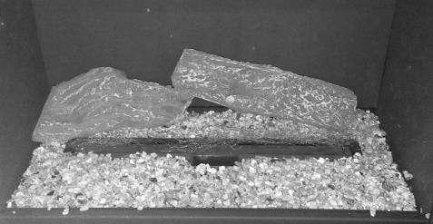
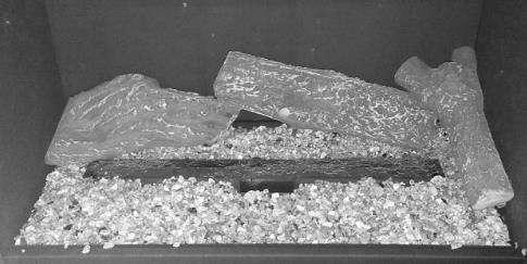
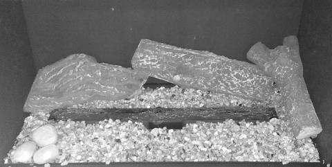
15 Section 8.1: FUEL BED LAYOUT Cover the base with Vermiculite provided making sure not to block the burner outlets and keeping an area around the pilot clear to help when cross lighting of the fire. Evenly place a layer of the stainless steel wool provided over the burner loosely to give the burning embers effect F Now Place each piece as per the pictures some adjust will be needed to ensure the flames go in between the pieces and not to be placed directly above the flames as this will create carbon deposits. 15

16 16
17 17
18 18
19 19
20 Remember some adjust will be needed to ensure the flames go in between and around the pieces and are not to be placed directly above the flames as this will create carbon deposits. WHEN FIXING THE GLASS BACK INTO POSITION PLEASE PUT ALL THE SCREWS IN HALF WAY AND THEN TIGHTEN FULLY INTO PLACE TO AVOID TWISTING THE FRAME 20
 Section 10.2: SPARK FAILURE The gap between the spark electrode and the pilot should be 3.5-4.5mm to produce a good spark.")
21 Section 10: COMMISSIONING THE APPLIANCE Turn on and test the gas supply up to the fire for any leaks, in accordance with current Approved Codes of Practice (ACOPs) Section 10.1: OPERATING THE APPLIANCE (See Section 16: Users Instructions) Section 10.2: SPARK FAILURE The gap between the spark electrode and the pilot should be mm to produce a good spark. There should be no need to adjust this. If under any circumstances the electric spark fails, the pilot may be lit manually by proceeding with the ignition sequence as previously described, and after turning the control knob through the spark position, the knob should be held in and the pilot lit with a taper. Note: Please ensure that the electrode spark igniters gap on the manual version has not been misaligned during the handling of the burner in this installation the gap should be 5mm from the burner. Section 11: SETTING THE GAS PRESSURE Remove the pressure test point sealing screw from the isolation elbow and attach a suitable pressure gauge. Check that the inlet gas pressure is at 20 mbar / Working Pressure at 20 mbar (+/- 1 mbar) Light the pilot and check the correct operation of the burner at all the flame settings. Always check that the gas has stopped flowing even if you hear the FSD valve close within the 3- minute period. Turn OFF the appliance and the gas supply and refit the pressure test point sealing screw. 21
22 SECTION 12: FLUE SPILLAGE MONITORING SYSTEM This fire is fitted with a flue spillage safety device (ODS), if the fire shuts down during use for no apparent reason then several things may be suspected, if a door or window has been opened creating a draught, then pilot disturbance is the problem, and removal of the draught should resolve this. The gas pressure reaching the fire must also be checked (again, recalls your installer to check and rectify any problem). The thermocouple connection into the back of the gas control valve may also have worked loose during installation, simply get the installer to tighten. If pilot disturbance is not the cause, then the ODS safety system may be in operation. Switch the appliance OFF, check the flue and carry out any remedial work required. Relight the fire and carry out a spillage test, DO NOT allow the appliance to be used if it continues to fail a spillage test. The aeration hole of the pilot must be carefully cleaned out on each annual service to ensure continued function of the ODS. The spillage monitoring system shall not be adjusted, modified, or put out of operation by the installer. Any spare parts fitted MUST be of a type supplied for the purpose by the appliance manufacturer. If the fire is not spilling, then further guidance should be sought, using the Troubleshooting section as a guide. SECTION 13: TESTING FOR SPILLAGE CHECKING FOR CLEARANCE OF COMBUSTION PRODUCTS Close all doors and windows in the room light the fire and allow to run for approximately 5 minutes on high position. After approximately 5 minutes, hold a smoke match just inside and below the centre of the lower front edge of the top of the fire, as shown below in Fig 1. All smoke generated should be drawn back into the flue, If slight spillage occurs or if in doubt, repeat the test after a further 5-10 minutes. If the test indicates that spillage is occurring and the flue restrictor baffle has been fitted, it should be removed and the test repeated after the fire has cooled, if spillage persists, the flue is not functioning correctly and a fault exists. If, after investigation the fault cannot be traced and rectified, the fire must be disconnected from the gas supply and expert advice obtained. After ensuring that the fire is safe to use it should be left on high position to fully warm up. During this time a slight odour may be noticed, this is due to the "newness" of the fire and will soon disappear. 22

23 Hold smoke match in position 10mm inside and down from top face of the central slot Fig 1 When the test has been completed satisfactorily, repeat with any extractor fans in the premises running on the highest setting, and any communicating doors open, finally, repeat with all doors open. DO NOT allow the fire to be used until the test is satisfactorily passed. SECTION 14: BRIEFING THE CUSTOMER All instructions must be handed to the user for safekeeping. Show the customer how to light and operate the fire. After commissioning the appliance, the customer should be instructed on the safe use of the appliance and the informed for the need of regular servicing. Frequency of service depends on usage, but MUST be carried out at least once annually. Cleaning of the fire may be achieved when the fire is cold using a damp cloth and mild detergent on most surfaces, with the exception of the ceramic fuel bed. A soft brush i.e. paint brush may be used to clean the ceramic fuel bed taken care not to use excessive pressure. Scratched and other superficial damage to the matt black paintwork of the appliance can be covered with matching heatproof spray. Use only the manufacturers recommended spray paint. Paint only when the fire is OFF and cold. Always mask off the surrounding area to prevent contamination with overspray. Ventilate the room during the use of the spray. DO NOT attempt to spray paint the coals or ceramics, or wash them in water. Advise that the fire will emit a newness smell for a time after initial commissioning and that extra ventilation may be needed during this time. Advise that the fire is fitted with a spillage safety device (O.D.S.). If the fire shuts down, this system may be in operation. If spillage is suspected, SWITCH APPLIANCE OFF and call in the installer to investigate any problems. 23
24 SECTION 15: SERVICING First Isolate the fire from the gas supply and ensure that the fire is fully cold before attempting service. Lay out the dust sheet and tools required. Remove Trim and Glass if applicable. Carefully remove the ceramic components Remove the screws that retain the tray in place and disconnect from the isolation tap. Remove the burner tray and other components as required (i.e. remote control box) Disconnect the gas supply, to the appliance and disconnect the isolation tap Remove convector box, Check the fireplace opening for rubble accumulation and remove, if debris is excessive, and initiate remedial work on the flue. Check the flue with smoke pellet for correct operation. Refit convector box using new seals where necessary Strip off the burner pipes and clean thoroughly. Clean out the injector, pilot assembly and burner tube. DO NOT remove the pilot injector. Re-assemble and re-fit the burner tray. Turn on the gas supply, and leak test. Refit the decorative casting and ceramics. Check any purpose provided ventilation is un-obstructed. Light the fire and test for spillage. Check setting pressure and safe operation of the appliance. SECTION 16: USER INSTRUCTIONS IMPORTANT NOTES The installation of this fire MUST only be carried out by a competent person (such as a Gas Safe registered fitter) in accordance with the Gas Safety (Installation and Use) Regulations 1998, the relevant British Standards, Codes of Practice, the Building Regulations and the manufacturers instructions. Failure to comply with the above recommendations could lead to prosecution and invalidate the appliance warranty. Please ensure you are handed all of the manufacturer s documents on completion of the installation. This will include these instructions. Always keep a note of the installer s name and address, the original purchase receipt and the date of installation for future reference. The fire and flue should be serviced regularly to ensure continued safe operation. See the servicing section for further details. Frequency of service will depend on use, but MUST be carried out at least once annually. Parts of this appliance become naturally hot during use. It is recommended that a suitable fire guard conforming to BS8423 is used, especially where young children, the elderly, or infirm are concerned. Combustible items, such as flooring and furniture, and soft wall coverings (such as blown vinyl or embossed paper) may discolour if fitted too close to the fire. See relevant section for further details on clearances to combustibles. No combustible material or flooring should protrude onto the hearth. 24
25 DO NOT burn any foreign material on this fire, the coals must be of the correct type and lay out in accordance with the relevant section of these instructions. Failure to do so could create a hazard or lead to sooting. Before the appliance is installed, the chimney should be swept. All flues should be checked by the installer to ensure there are no defects or obstructions that may prevent the flow of combustion products. The fire is only suitable for use with the gas type for which it is supplied. This fire is supplied with a particular style of fire front/fret. Use of the fire front/fret will ensure an adequate airflow under the fire bed for the correct functioning of this appliance. Compliance with safety standards cannot be guaranteed if another style of front is used. A combustible shelf may be fixed to the wall above the fire, providing that it complies with the dimensions given in section 3 site requirements. No purpose provided ventilation is normally required for this appliance. The requirements of other appliances operating in the same space or room, and the results of a spillage test must be taken into consideration when assessing ventilation requirements; this will have been carried out by your Gas Safe registered installer. The appliance is fitted with an atmospheric sensing device designed to shut of the fire in the event of the flue being partially or completely blocked causing a build-up of combustion products in the room that the appliance is operating, if the fire repeatedly turns itself off then contact a gas safe installer to investigate the fault. For Republic of Ireland, ventilation may be required, see IS 813, ICP3, IS 327, and any other rules in 25

26 SECTION 17: OPERATING THE APPLIANCE (Remote Control) The Remote Control with this appliance has already been paired at the Factory Quick start user instructions Fire Control This control is situated on your fire. The drawing shows the main features of the control. The control required 3 x AA size alkaline batteries to be inserted under the battery compartment cover. The orientation of these is shown moulded into the battery compartment. After fitting the batteries and replacing the cover the fire can now operate. Slide the slide switch to the right to the ON position. To start the fire, press the power button and hold for 1 second then release. The burner will within around 1 to 2 seconds, adjust to the maximum power setting, The power of the burner can be adjusted up and down by pressing the or + buttons. To stop the fire, simply press the power button again and the burner will stop. If you are not intending to use the fire for a long period (i.e. over summer time months), the battery life can be extended even more by sliding the white isolator switch to the left (away from the on position). IF USING THE MAINS ADAPTOR THIS IS FITTED INTO THE VALVE AT THE BOTTOM LEFT HAND SIDE Ensure the very small white slider switch on the front corner of Fire Control is in the on position. Grasp around the handset to unlock its functions. The green unlock light will illuminate to show when the handset is unlocked and ready to accept commands. (N.B. Keep a grip of handset to keep it unlocked, to continue to operate the command buttons.) For your safety, the fire is fitted with a Flame Supervision Device (FSD), which will shut off the Gas supply if for any reason the pilot is extinguished. 26


27 The Valve and Handset Have Already Been Paired First set up the hand set, cup the handset the green unlock light will illuminate. Keep it held to keep the control unlocked, to enable operation of the buttons. 3) Setting the time the display will be as shown, as the time is not set yet and will progress automatically to the next screen shown below. Note: the indicator at the bottom shows the battery condition of both the batteries in the hand set and in the fire control within the fire. RC = Remote Control / FC = Fire Control. The control is designed to get the most out of the batteries but when eventually the display shows they are spent (when the battery indicator is empty, we recommend you change the batteries in the handset before they are flat, to avoid having to re-program the time of day in again. N.B. Pairing is not lost, even if the batteries are removed or flat. 4) Setting the display for 12 or 24 Hour display As always when pressing the remote control buttons keep the control held to keep the green light on and therefore handset safety feature, unlocked. The H indicates that it is time to set the timer to either 24 hour display or 12 Hour (AM or PM) display. Press the + or button on the handset to toggle between the two settings. When you are ready to confirm the setting you want press the SET button to progress to setting the day of the week. 27
.")


28 Setting the day of the week Press and release the + and buttons until the correct day of the week is shown on the display. (Mo = Monday, Tu= Tuesday, We=Wednesday, Th=Thursday, Fr=Friday, Sa=Saturday and Su=Sunday). Press SET to accept the day of the week and to progress to setting the Hour of the day. Note: Whilst doing this setup pressing SET advances to the next display and pressing MODE will return you to the previous display setting. Setting the Hour Press and release the + or button to change the hour to the correct hour and press set to store and to move to setting the minute. Repeat this for setting the minutes. Setting the temperature display to Celsius or Fahrenheit. Press and release the + or - button to toggle between C and F. When the display shows the desired symbol, press and releases the SET button to store. As the important settings above have now been done. Press and hold (not releasing straight away) the SET button for a few seconds and this will exit the setup menu. The control is now ready for use with the Fire Control. 28

29 Quick start user instructions First set up the hand set, cup the handset the green unlock light will illuminate. Keep it held to keep the control unlocked, to enable operation of the buttons. Then with the other hand touch and keep you finger on the power button for about 5 seconds. (Upon touching the power button the green light will do a single flash to show command is recognized after 5 seconds the green light will flash for a second time, at which you should release your finger). The Fire should be lit within a few seconds. (N.B. If power button is held for more than a few seconds after second flash/beep, the command ignored for safety reasons. With this system, the control has been designed to ensure that only intended ignition of the fire occurs.) To stop with handset held to unlock it, press then release power button. 29
30 Mode Man = Manual Zzz = Snooze Therm = Thermostat Timed In Range of the fire If missing out of range or fire switched off Day of the Week Time (12 or 24hr) Room Temperature Fire Status Battery Indicator RC = Handset FC = Fire Control Light Sensor (for Display Backlight) To Change Mode Handset Unlocked if Illuminated To Change Settings see handbook Press to Decrease Power Button To Increase Flame 30
 If display is not as above the handset may well need to be reset before pairing.")

 until the handset makes a noise and the display shows the pattern as shown here.")
31 Operating instruction (Detailed) 1) Upon successful insertion of the batteries in the Handset (if the handset has not previously paired) the display will be as shown if it has been paired already then go to No 3. 1a) If display is not as above the handset may well need to be reset before pairing. Press and Hold Set Button, to enter Programing menu When Set Up is flashing, press and release set to enter Setup Mode. Press and Release the Set button several times until you see CAO displayed. Then press and release + button once to change display to CA1 Press and Release the Set button once more to display TESC, handset is now ready to pair. 2) Pairing the Handset to the Fire Control After fitting the batteries as above (and with the isolator slide switch on the TESC Fire control in the ON position), simultaneously press and hold the and + buttons on the fire control (i.e. not the handset) until the handset makes a noise and the display shows the pattern as shown here. Hold the handset in one hand so your fingers wrap around the back of the operating buttons area of the handset. A green unlock light will illuminate when the handset has detected your hand. The green light must be illuminated in this way for any of the command buttons to accept commands 31
32 to operate the fire control. Whilst the display is as shown, and holding the handset as described, press the SET button with the other hand to finish off the pairing of the handset to the Fire Control and to enter to setup the time of day on the handset. N.B. If the display returns to the one shown above with the word TESC shown, then too much time has passed before pressing SET and so the handset has not paired yet. Simply repeat pairing again. Advanced settings Menu In the event that you may want to change the other pre-set settings of the control features. Do not do a long press and hold above but a normal short press and release will take you into the advanced settings area. Advanced settings options are:- Back light o A = Automatic (default setting). The back light comes on in the dark but not in the light. o 0 = Light never comes on. o 1 = Light comes on whenever handset is unlocked. Display contrast 8 levels from 0 to 7 (default level 4). P = pairing with other devices other than the fire control. The hand set can pair with other modules to:- o L= Operate an electric light which is the dimmable in 9 steps o F= operate an electric fan which can have 9 speed levels o A= operate an auxiliary contact to operate another device. Note: Fitting the batteries incorrectly could lead to damaging your Valve. Different types of batteries or old and new batteries are not to be mixed. Only batteries of the same or equivalent type as recommended are to be used. Batteries are to be inserted with the correct polarity. Exhausted batteries are to be removed from the fire. The supply terminals are not to be short-circuited. Do not use rechargeable batteries. Non-re-chargeable batteries are not to be recharged. Do not mix old and new batteries. Do not mix alkaline, standard (carbon zinc) or re-chargeable batteries. 32
33 SECTION 17a: Remote Error Trouble Shooting Guide Code Comment Appearance Possible Cause Action E00 TESC locked due to failed ignition Red Led is permanently on TESC unit ( and E00 on handset, if used) Temporary air disturbance around pilot burner No gas on appliance inlet Pilot contaminated with lint or other materials Reset control by pressing start button for 1 second and releasing. The press again the same way to attempt a normal start command. Repeat up to 10 times as necessary to see if this overcomes the issue as it may resolve itself eventually. Check to see if gas is present at gas appliance inlet. (Check gas supply is on, the gas line purged of air and the supply pipework is free of blockages or contamination) Clean the pilot fee of any dirt, dust carbon granules or lint, especially around the brass body of the Bunsen burner and its gas and electrical connection and the area around the flame ports and the spark plug and electrode tip. Check the electrode gap is 3-4 mm. Rectify and perform start cycle to clear the Error code. Try to light the fire as normal. Rectify and perform start cycle to clear the Error code. Try to light the fir as normal. Replace pilot if necessary E01 Low current from thermocouple but flame: possibly CO alarm Flashing Red LED on TESC Control No Spark at Electrode (fire not igniting pilot burner) Pilot pipe or pilot injector could be blocked Pilot pipe blocked - no gas reaching pilot burner Chimney blocked causing Co / Co2 to build up in the room Check ignition cable for damage and listen and watch for tracking out of spark to see if it is present but not making it to the electrode tip on the pilot burner. Clear pipe and consider changing pilot Check pilot pipe, check flame appearance of pilot flames Check flue If cable damaged, replace cable. Reset error by performing a normal start cycle and try to start again. Replace pilot if necessary. 33
34 Pilot thermocouple defective / old Possible temporary air disturbance on pilot flame Change pilot or thermocouple Clear error and restart to check ignition ok Code Comment Appearance Possible Cause Action E02 E03 E04 E05 too high ambient temperature ( >73 C) around control no, defective, or bad connected thermocouple false flame signal false flame signal Negative flue pull or blocked flue or similar Occurs if started ok then subsequently loss of thermocouple current. Check for flue problems. Fire cuts out to prevent over heating Reset and try again Blocked flue Check and clear Reset and try again Poor position of Ceramic parts Bad connection defective thermocouple occurs during stopping fire Flame sensing on pilot before start of ignition sequence or after valve has shut off. Contamination of electrode to ground Check manual for correct placement Check if connected are correct and terminals are sound Replace Pilot Sensing flame on pilot when no flame should be there. Investigate. Check if and clean around the area of the pilot for lint and other contamination and clean. Check where the thermocouple connect to the TESC control for the same contamination. Clean these areas. Reset and try again Reset and try again Reset and try again Reset and try again Reset and try again E06 E07 E08 too low voltage on power supply to start the burner power supply breakdown during peak current consumption error caused by external pressure switch Weak or old or defective batteries Check/change all the batteries or check power adaptor. : Note always change all batteries together never only 1 or 2 Check the pressure switch Replace batteries Replace batteries / power adaptor Replace if necessary Reset and try again Reset and try again Reset and try again 34
35 E09 E10 Jumpers on back of valve missing error caused by external pressure switch error caused by external pressure switch Check to see if jumpers are in 10 way connector pressures switch action connection or jumpers missing or not connected properly pressures witch action connection or jumpers missing or not connected properly Check pressure switch connections, check to see if jumpers are in place on back of TESC. Check pressure switch connections, check to see if jumpers are in place on back of TESC. Reset and try again Reset and try again Reset and try again Code Comment Appearance Possible Cause Action E11 E12 E13 E14 E15 short circuit on wired thermostat (if used) open circuit on wired thermostat (if used) wired thermostat is out of tolerance button (-) sticks either on TESC or on wired control panel (if used) button (+) is shorted to other buttons either on TESC or on wired control panel (if used) Check switch Check wiring and thermostat Check wiring and thermostat Check for contamination around buttons Check for contamination/ damage - Check switch for damage, contamination across terminals or damaged wiring. Disconnect wired thermostat if fitted and try a start, if it works replace thermostat Check switch for damage, contamination across terminals or damaged wiring. Disconnect wired thermostat if fitted and try a start, if it works replace thermostat Check switch for damage, contamination across terminals or damaged wiring. Disconnect wired thermostat if fitted and try a start, if it works replace thermostat Clean as necessary. Replace switch panel as necessary if damaged or too contaminated. Disconnect wired control panel and try again if it works replace wired control panel Clean as necessary. Replace switch panel as necessary if damaged or too contaminated. Disconnect wired control panel and try again if it works replace wired control panel Reset and try again Reset and try again Reset and try again Reset and try again Reset and try again E16 button (ON/OFF) is shorted to other buttons either on TESC or on wired control panel (if used) Check for contamination / damage and replace wired switch panel if necessary Clean as necessary. Replace switch panel as necessary if damaged or too contaminated. Disconnect wired control panel and try again if it works replace wired control panel Reset and try again 35
36 E17 button (-) is shorted to other buttons either on TESC or on wired control panel (if used) Check for contamination / damage and replace wired switch panel if necessary Clean as necessary. Replace switch panel as necessary if damaged or too contaminated. Disconnect wired control panel and try again if it works replace wired control panel Reset and try again E18 E19 E20 button (AUX) is shorted to other buttons on switch panel Infrared receiver defective (if used) Incorrect setup parameters Check for contamination / damage and replace wired switch panel if necessary Check connection of IR or damage - replace if necessary IR eye Check connection of IR or damage - replace if necessary IR eye Clean as necessary. Replace switch panel as necessary if damaged or too contaminated. Check if wired correctly and replace IR eye if necessary Check if wired correctly and replace IR eye if necessary Reset and try again Reset and try again Reset and try again Code Comment Possible Cause Action E21 tried to config a TESC as Cluster slave while a wired thermostat is connected Factory assembly warning on setup configuration not a maintenance error Usually only a factory assembly error. Could happen if done in error in servicing. E22 E23 tried to calibrate TESC with TESCeasytest while a wired thermostat is connected warning: end of life is near, should be replaced soon Not field error Not field error Disconnect thermostat before attempting to use Easy test unit. Indicated that control has performed a high number of operations and so fire should be serviced and control replacement should be considered as preventative maintenance. (Should not really occur before 10 years from new, depends upon usage). Reset and try again Reset and try again Reset and try again 36
37 E24 Thermocouple doesn't reach final current - damaged or aged Replace Pilot Check pilot connections Pilot pipe may be blocked completely Check and correct Thermocouple wiring. Replace thermocouple if necessary Check and correct Thermocouple wiring. Replace thermocouple if necessary Clear pipe, replace pilot as necessary Reset and try again Reset and try again Reset and try again E25 E26 E48 E49 Poor thermocouple signal defective or wrong wired USB-power supply short circuit on thermocouple, or thermocouple reversed polarity false flame signal Tired or bad connection of thermocouple or bad or unstable flame on pilot or poor grounding return try again and if repeatedly fails replace Wrongly wired Flame detected during operation of fire when it should not be detected - contamination of electrode circuit to ground Check pilot thermocouple connections and connections to TESC Replace with new USB power supply of the correct type. Check and correct Thermocouple wiring. Replace thermocouple if necessary Check if and clean around the area of the pilot for lint and other contamination and clean. Check where the thermocouple connect to the TESC control for the same contamination. Clean these areas. Reset and try again Reset and try again Reset and try again Reset and try again E50 internal error Flame detected during operation of fire when it should not be detected - contamination of electrode circuit to ground Check if and clean around the area of the pilot for lint and other contamination and clean. Check where the thermocouple connect to the TESC control for the same contamination. Clean these areas. Reset and try again E51 error caused by external pressure switch Check pressure switch connections, check to see if jumpers are in place on back of TESC. Reset and try again 37
38 SECTION 18: CLEANING THE COALS Open the glass door Remove the ceramic components. Gently clean in the open air using a dry paint brush. Be careful not to create dust from the ceramics. Where necessary replace damaged components with genuine spares. Seal scrap ceramic components in plastic bags and dispose at proper refuse sites as directed. Re-fit the ceramics by referring to the relevant section of these instructions. GENERAL CLEANING Before carrying out any of the following operations, ensure that the fire is OFF and completely cold. Debris that may form on the fire bed should be periodically removed by a competent person. Large deposits could indicate deterioration of the flue. This should be repaired by a competent person, and the fire serviced before further use. FIRE FRONT/FRET - Any dust accumulating in the fire front may be removed using a vacuum cleaner or dry cloth. Heavy stains may be removed by using a damp cloth and mild household detergent. Brass parts of the fire front may be cleaned using a suitable brass cleaner. Replace the front centrally against the fire after cleaning. PAINTED AREAS - These can be cleaned using a dry cloth. GLASS - Remove the Glass panel as shown on page 10 and 11 please follow the instructions carefully and clean glass with a glass cleaner and a lint free cloth or Microsoft cloth, if white haze or carbon discolouration is still apparent the a metal polish such as Hotspot or Peek can be used to remove these stubborn particles, when securing the glass in place please secure all screw half way before fully tightening the glass to avoid twisting the glass door. 38
39 SECTION 19: WARRANTY IMPORTANT INFORMATION ABOUT WARRANTY SERVICE FOR THE END USER WARRANTY REGISTRATION IS REQUIRED WITHIN 28 DAYS FROM DATE OF PURCHASE It is in your interest to register your appliance with Sirocco as soon as possible BEFORE CONTACTING SIROCCO FOR SERVICE PLEASE READ THE FOLLOWING; Sirocco is committed to customer care and service. To ensure we provide the best service we can we have a policy to charge for all none warranty home visits so that all customers with a genuine manufactures fault can be dealt with swiftly, if your appliance has recently been installed and you are experiencing any of the following; Fumes are spilling from the flue/fire The pilot light cuts out after a few minutes The fire controls are getting too hot Excessive sooting is forming on the fuel bed Poor flame picture Remote controls are not working These symptoms tend to be chimney/flue or installations related and as such mostly are not covered by your warranty and are mostly dealt with in the installation instructions, DO NOT USE YOUR APPLIANCE and in the first instance contact your installer to investigate these further, to establish their cause before contacting Sirocco. CONTACTING SIROCCO FOR WARRANTY SERVICE OR TO PURCHASE SPARE PARTS In the event of a service or parts claim please note that some parts such as ceramics, batteries, trims and fronts etc. are categorized as user serviceable parts and are not carried out by a service visit. Please ensure you have the following information at hand when you contact Sirocco; The full serial number which is located on the data badge of the appliance Your receipt of purchase showing the date and where purchased from Your installers details You can contact Sirocco`s representative in the UK by phone to obtain advice and a warranty service form on; Or you can complete a form on line at follow the link at the top right hand side on the home page. SIROCCO Sp. Zo.o Nad Lasem 8, Zelecow, Zabia Wola, Poland. Tel , Fax Further information, contact details and facilities are available through our website; 39

 PRT THERM RC NG VAL")


40 SECTION 20: LIST OF SPARES Code Spares PART NUMBER G1 Replacement glass panel with door PRT GLA SIR 60 BL FR 1 E 1 Engine (remote) Excluding ceramics with Handset PRT VOL 60 N RC ENG 1 R 1 TESC Remote Gas Valve (Only) PRT THERM RC NG VAL 1 R 2 Remote hand set PRT THERM RO HS 1 R 3 Remote assembly Thermaco ERTA NG OXI-PG PRT VAL PI RO PL Therm 1 C 1 Vermiculite chippings PRT CER SIR 60 VER C 2 HT wire wool PRT CER SIR 60 WW C 3 New Forest Log Set PRT CER SIR 60 NF 1 C3 R2 R1 R3 40
41 SECTION 21: CONTACT DETAILS GENERAL HELP LINE Mon to Fri 9:00 to 16:00 SPARE PARTS If you need assistance or wish to purchase spare parts Mon to Fri 9:00 to 16:00 Contact our spares department by Purchase spare parts direct from our website Spare parts are managed by our UK partner company Lodestar-Delta Ltd Lodestar-Delta Ltd T/A Sirocco Unit 1, 11 Weir St, Blackburn, Lancashire BB2 2AN SIROCCO HEAD OFFICE Telephone number for all departments (charged at BT national rate) Mon to Fri 10:00 to 15:00 Contact us by View our latest products and use our on line services; Nad Lasem 8, Zabia Wola Zelechow Poland WARRANTY AND SERVICE For warranty registration or for a home service call: For assistance to complete a registration or a home service Call us on Mon to Fri 9:00 to 16:00 41
42 Our warranty statement 5 YEAR WARRANTY STATEMENT You have purchased your new Sirocco appliance that has been made to the highest standards. When properly maintained and used the appliance will perform perfectly for many years, and is warranted for 12 months from date of purchase for parts and labour as covered by the terms and conditions of warranty, verification may be required of the defect by a Sirocco engineer, or a Sirocco appointed engineer, provided that such parts have been subjected to normal conditions of use. In addition there is a further 4 year parts only warranty available at no extra cost; this is limited to the repair or replacement of parts found to be defective. To qualify please ensure the appliance is serviced every year as required by law and that a service kit is used which is available direct from Sirocco Registration of guarantee and Sirocco Sp. zo.o has a commitment to quality as regards customer care and service and therefore it is important that you and your installer complete your warranty form completely and correctly and return it to us within 28 days of date of purchase. Alternatively you can complete the form on line at and follow the link on the home page headed guarantee registration. In addition a gas safety certificate must be issued by the installer and you are required by law to register the appliance within 30 working days with the local authority building control and you will find this information to assist you on the same location as the guarantee registration. This guarantee applies to gas fires only, electrical appliances are not included. By registering you will assist us in identifying the correct parts you may require in the future, or ensuring that the correct parts are given to an engineer for a service visit. Please ensure you provide this to us within 28 days stated, and include the Gas Safe notification number or your warranty will not be valid. Regular Servicing It is essential that your Sirocco appliance is serviced, by a suitably qualified Gas Safe engineer or a Sirocco authorised appointed engineer to carry this out at least within each twelve month period as required by law, and to qualify for your 5 year warranty. It should be noted that that each appliance has different requirements for parts to be replaced at a service and you should consult and purchase the service packs form the sirocco website relevant to each model and service interval as part of the conditions of your 5 year warranty Contacting Sirocco If you need to contact Sirocco for a Warranty service or to purchase spare parts the contact details and procedure are printed on the back page of your installation/user guide What else should I know? The following is an extract from the full terms and conditions for warranty which are located in your instruction/user guide and on the Sirocco website. The following are not covered by warranty: paint work in the fire chamber, fire fronts, and decorative trims, crazing of ceramic components, and marks or clouding on glass, batteries, electronic or electric/mechanical components such as remote controls. The warranty is only valid if registered within 28 days of purchase providing all the information stated (proof of purchase will be required and a gas safety certificate must be issued by the engineer on installation and with every service) registration with the local authority via Gas Safe is mandatory and is only for a UK domestic installation, provided the appliance has been installed in accordance to the installation instructions and in compliance with current regulations in a correctly functioning flue. Validation of your installation will be required prior to warranty service/repair; there will be a fee for this. No other validation will be accepted by Sirocco. Accidental damage or improper use is not covered by warranty. This guarantee is non-transferable and is made to the original owner provided that the purchase was made through an approved Sirocco Fires stockist 42


43 This guarantee is none transferable and is made to the original owner, provided that the purchase was made through an company appointed stockist Any installation, labour, transportation or other related costs expenses arising from defective parts repair replacement or otherwise of same will not be covered by this guarantee nor shall the company assume responsibility for same. Furthermore the company will not be responsible for any incidental, indirect or consequential damages except as provided by law. All other guarantees expressed or implied with respect to the product, it s components and accessories or any obligations or liabilities on the part of Sirocco Fires are hereby expressly excluded. Sirocco Fires neither assumes nor authorises any third party to assume on it s behalf, any other liabilities with respect to the sale of this Sirocco Fire appliance. Location of your serial number, this will be on the data badge on the appliance which will look something like this and will be located under the fire or behind the fascia. For full terms and conditions of warranty please refer to our website 43
44 DATE OF PURCHASE AS IT APPEARS ON YOUR RECEIPT COMPLETE THE FORM USING CAPITALS SERIAL NUMBER (WHICH IS SHOWN ON THE DATA BADGE OF THE APPLIANCE) MR MRS MISS INITIALS. SURNAME HOUSE NUMBER ADDRESS TEL NUMBER POST CODE ADDRESS WHERE YOU PURCHASED YOUR APPLIANCE FROM NAME ADDRESS POST CODE YOUR INSTALLER MUST COMPLETE ALL SECTIONS IN THIS PART AND SIGN THE FORM NAME ADDRESS TEL NUMBER GAS SAFE REG NUMBER THE WORKING PRESSURE OF THE FIRE IS (on high setting) THE STANDING PRESSURE OF THE FIRE IS mbar mbar GAS RATE FLUE - SPILLAGE TEST PASS FAIL FLUE - FLOW TEST PASS FAIL DOES VENTILATION MEET APPLIANCE REQUIREMENTS YES NO SIGNED BY INSTALLER PRINT NAME DATE PLEASE KEEP YOUR RECEIPT AND CP1 CERTIFICATE IN A SAFE PLACE AS THEY WILL BE REQUIRED 44
45 SIROCCO Sp. Zo.o C/O UNIT 1 THE WEIRS 11 WEIR STREET BLACKBURN LANCASHIRE, BB2 2AN PLEASE AFFIX STAMP HERE FOLD HERE 45


46 Vola 6x6 & Vola 600 Instructions for frameless kit Remove the burner tray from the fire box by the following steps shown below: Fig 1. Carefully lift the the ceramic base boards to reveal the burner screws Fig 2. Remove 6 screws Fig 3. Remove access panel Fig 4. Disconect gas supply


47 Fig 5. Carefully remove the burner tray bhy lift the back of tray first You require to reposition the isolation bracket for frameless version Burner tray showing standard bracket Burner tray with framless bracket option 1. Remove bracket and retain the screws 2. Fold the new bracket to the shape shown 3. Fit the bracket using the new location holes as below 4. Fit the isiolation valbve to the bracket


48 Now fit the remote control valve key operating mechanism and power supply as follows: 1. Place the screws into the holes of the key mechanism and fix to the bracket on the remote control valve If using a back panel with this installation ensure the keys fit above the panel as shown in Fig 2 Fig 1 Fig 2 Plug the power supply cord into the USB socket on the side of the remote control valve ensuring the cord is routed away from any hot surfaces and the grommet provided is used to prevent chafing to the cord when passing through the fire box


49 Press to Decrease flame Power To Increase Flame Button The key mechanism will now give you manual control of the remote valve as shown above The keys have a small movement of approx 1mm Re fit the burner tray and fix in place the sub frame as shown below Fig 1 Fig 2 If you using the back panel kit for this installation it should be fitted now by following the instructuons that are provided with the panel
Apex X2 HE Apex X3 HE
 Apex X2 HE Apex X3 HE Installation and User Instructions FRAMELESS AND INTEGRATED SUITE INSTRUCTION ARE SEPARATE AND MUST BE READ IN CONJUNCTION WITH THESE INSTRUCTIONS BEFORE INSTALLATION STARTS All instructions
Model Apex Falcon, Titan & Zenit
 Model Apex Falcon, Titan & Zenit Installation and User Instructions All instructions must be handed to user for safekeeping This is not a DIY product and must be installed by a Gas Safe registered installer
Apex. Model Options Liberty 6 & 10. Information & Installation Guide
 Apex Model Options Liberty 6 & 10 Information & Installation Guide This is not a DIY product and must be installed by a Gas Safe registered installer The information contained herein is not meant to replace
APEX Cirrus X1. Installation and User Instructions
 APEX Cirrus X1 Installation and User Instructions All instructions must be handed to user for safekeeping This is not a DIY product and must be installed by a Gas Safe registered installer Edition H 10/15
INSTALLATION & USER INSTRUCTIONS INSET DECORATIVE GAS FIRE
 INSTALLATION & USER INSTRUCTIONS INSET DECORATIVE GAS FIRE MODELS COVERED BY THESE INSTRUCTIONS HANNINGTON BRASS F500310 HANNINGTON BLACK F500311 Focal Point Fires plc. Christchurch, Dorset BH23 2BT Tel:
Model Apex Adara Slimline HE
 Model Apex Adara Slimline HE Manual Control Installation and User Instructions All instructions must be handed to user for safekeeping This is not a DIY product and must be installed by a Gas Safe registered
Apex. Adara HE. Installation and User Instructions
 Apex Adara HE Installation and User Instructions All instructions must be handed to user for safekeeping This is not a DIY product and must be installed by a Gas Safe registered installer Edition D 09/15
CF1 L GAS APPLIANCE THE CONNELLY COLLECTON INSET CONVENTIONAL FLUED GAS FIRE
 1 valentine s buildings Bechers drive Aintree racecourse Business Park L9 5ay CF1 L GAS APPLIANCE THE CONNELLY COLLECTON INSET CONVENTIONAL FLUED GAS FIRE INSTALLATION & USERS INSTRUCTIONS FOR USE WITH
CRYSTAL FIRES. Inset Conventional Flue Fire. (BOSTON/MIAMI) Cf1 and MANHATTAN USER INSTALLATION AND SERVICING INSTRUCTIONS
 Cf1 and MANHATTAN USER INSTALLATION AND SERVICING INSTRUCTIONS") CRYSTAL FIRES (BOSTON/MIAMI) Cf1 and MANHATTAN Inset Conventional Flue Fire USER INSTALLATION AND SERVICING INSTRUCTIONS FOR USE WITH NATURAL GAS G20 @ 20 mbar For use in GB and IE CE THESE INSTRUCTIONS
CRYSTAL FIRES (BOSTON/MIAMI) Cf1 and MANHATTAN Inset Conventional Flue Fire USER INSTALLATION AND SERVICING INSTRUCTIONS FOR USE WITH NATURAL GAS G20 @ 20 mbar For use in GB and IE CE THESE INSTRUCTIONS
INSTALLATION & USERS INSTRUCTIONS. FOR USE WITH NATURAL GAS 20 mbar For use in GB and IE
 1 valentine s buildings Bechers drive Aintree racecourse Business Park L9 5ay CF1 L GAS APPLIANCE INSET CONVENTIONAL FLUED GAS FIRE INSTALLATION & USERS INSTRUCTIONS FOR USE WITH NATURAL GAS G20 @ 20 mbar
Ethos Landscape & Portrait Remote Control
 Ethos Landscape & Portrait Remote Control - Log, Pebble & Driftwood Effect - Inset Live Fuel Effect Radiant Convector Fire Installation and Users Instructions These instructions should be read by the installer
(manual control) (ezi-slide control) INSET COAL EFFECT GAS CONVECTOR FIRE V1/100/B INSTALLATION & USER INSTRUCTIONS
 (ezi-slide control) INSET COAL EFFECT GAS CONVECTOR FIRE V1/100/B INSTALLATION & USER INSTRUCTIONS") Model Number: V1/100/A V1/100/B (manual control) (ezi-slide control) INSET COAL EFFECT GAS CONVECTOR FIRE INSTALLATION & USER INSTRUCTIONS GB IE SUITABLE FOR USE ON NATURAL GAS (G20) AT 20mbar SUPPLY PRESSURE
Model Number: V1/100/A V1/100/B (manual control) (ezi-slide control) INSET COAL EFFECT GAS CONVECTOR FIRE INSTALLATION & USER INSTRUCTIONS GB IE SUITABLE FOR USE ON NATURAL GAS (G20) AT 20mbar SUPPLY PRESSURE
Decorative Fuel Effect Appliances
 Decorative Fuel Effect Appliances Technical Manual User and Installation Instructions for CUBB22US Available in Natural Gas. 1 Contents Section Pages 1 Unpacking 3 2 Installation Parameters 4 3 Installation
INSTALLATION & USER INSTRUCTIONS
 INSTALLATION & USER INSTRUCTIONS STONE EFFECT DECORATIVE GAS FIRE MODELS COVERED BY THESE INSTRUCTIONS POLARIS GB IE Focal Point Fires plc. Christchurch, Dorset BH23 2BT Tel: 01202 499330 Fax: 01202 499326
Passion CONVENTIONAL FLUE LOG EFFECT GAS FIRE
 Passion CONVENTIONAL FLUE LOG EFFECT GAS FIRE Installation, Maintenance & User Instructions Hand these instructions to the user Model No. BLBL**RN & BLBL**TN is only for use on Natural Gas (G20) at a supply
Ethos 400 Stove. Installation and Users Instructions. - Log Effect. - Live Fuel Effect Radiant Convector Stove
 Ethos 400 Stove - Log Effect - Live Fuel Effect Radiant Convector Stove Installation and Users Instructions These instructions should be read by the installer before installation and then should be handed
INSTALLATION INSTRUCTIONS COMPACT GAS STOVE MODEL NUMBER 550
 INSTALLATION INSTRUCTIONS COMPACT GAS STOVE MODEL NUMBER 550 Before installation ensure that the local distribution conditions (identification of the type of gas and pressure) and the adjustment of the
CLASSIC II QUATTRO DECORATIVE FUEL EFFECT APPLIANCES FOR USE WITH NATURAL GAS IIN INSTALLATION, SERVICING & USER INSTRUCTIONS
 CLASSIC II QUATTRO DECORATIVE FUEL EFFECT APPLIANCES FOR USE WITH NATURAL GAS IIN INSTALLATION, SERVICING & USER INSTRUCTIONS THESE INSTRUCTIONS MUST BE LEFT WITH THE USER MANUFACTURED BY: MULTIGLOW FIRES
ULTIMATE INSET LIVE FUEL EFFECT GAS FIRE MODEL 417 OWNER GUIDE
 ULTIMATE INSET LIVE FUEL EFFECT GAS FIRE MODEL 417 OWNER GUIDE THE NATURAL GAS MODEL IS FOR G20 AT A SUPPLY PRESSURE OF 20mbar THE PROPANE GAS MODEL IS FOR G31 AT A SUPPLY PRESSURE OF 37mbar THESE APPLIANCES
NIGMA. Fuel Effect Gas Fire INSTALLATION, SERVICING AND USER INSTRUCTIONS. All instructions must be handed to the user for safekeeping
 Σ NIGMA Fuel Effect Gas Fire INSTALLATION, SERVICING AND USER INSTRUCTIONS All instructions must be handed to the user for safekeeping Revision A 09/03 Country(s) of destination: GB, IE Focal Point Fires
installation and user instructions
 installation and user instructions All instructions must be handed to user for safekeeping Revision A - 06/09 Country(s) of destination - GB/IE eko 00 fuel effect gas fire INSTALLATION INSTRUCTIONS Preliminary
EMBERGLOW CLASSIC RADIANT CONVECTOR GAS FIRE. Installation and Maintenance Instructions
 , EMBERGLOW CLASSIC RADIANT CONVECTOR GAS FIRE Installation and Maintenance Instructions Hand these instructions to the user Model No. FEMC00MN is for use on Natural Gas (G20) at a supply pressure of 20
Ecoburn Plus Medium Gas
 Ecoburn Plus Gas Ecoburn Plus Medium Gas PLEASE RETAIN THIS GUIDE FOR FUTURE REFERENCE BS EN 613: 2001 + A1: 2003 +C1:2008 BK710 SPECIFIC Rev 02 ISSUE DATE : 28/11/2017 Ecoburn Plus Gas Arada Ecoburn Plus
GB IE INSTALLATION & USER INSTRUCTIONS. Model Number: V1/300/B (ez-slide control) HIGH EFFICIENCY INSET COAL EFFECT GAS CONVECTOR FIRE
 HIGH EFFICIENCY INSET COAL EFFECT GAS CONVECTOR FIRE") Model Number: V1/300/B (ez-slide control) HIGH EFFICIENCY INSET COAL EFFECT GAS CONVECTOR FIRE INSTALLATION & USER INSTRUCTIONS GB IE SUITABLE FOR USE ON NATURAL GAS (G20) AT 20mbar SUPPLY PRESSURE These
Model Number: V1/300/B (ez-slide control) HIGH EFFICIENCY INSET COAL EFFECT GAS CONVECTOR FIRE INSTALLATION & USER INSTRUCTIONS GB IE SUITABLE FOR USE ON NATURAL GAS (G20) AT 20mbar SUPPLY PRESSURE These
installation and user instructions
 installation and user instructions All instructions must be handed to user for safekeeping Revision A - 08/09 Country(s) of destination - GB/IE eko 4010 eko 400 high efficiency fuel effect gas fire Eko
INSET LIVE FUEL EFFECT GAS FIRE
 600B741/02 OWNER S GUIDE MODEL BR650 VA (GC No. 32-032-39) INSET LIVE FUEL EFFECT GAS FIRE THIS APPLIANCE IS FOR USE WITH NATURAL GAS (G20) WHEN CONVERTED USING CONVERSION KIT NO.591149 THIS APPLIANCE
Model Eco4 HE. Model options. E4 HE Plus, E4 HE Nova, Extra HE
 Model Eco4 HE Model options E4 HE Plus, E4 HE Nova, Extra HE Apex, Blenheim, Cristal, Grace, Daisy, Soho, Contemporary, Contemporary II, Ignite, Fairfield, Magma HE, SP200, MX20, Pinnacle Slimline HE,
MODEL 466 Radiant / Convector Gas Fire Black Beauty
 I N S T A L L E R G U I D E MODEL 466 Radiant / Convector Gas Fire Black Beauty Please keep in a safe place for future reference 600A734/02 Please leave this Installer Guide with the user This appliance
Model. Eco2 MkIII. Design options
 Model Eco2 MkIII Design options Apex, Adjusta, Aleda, Black-Watch, Cristal, Contemporary, Fairfield, Liberty, Caledonian, Lux, Ignite, Maine, Mystique, Pinnacle, Sirius Westerly, Verto Installation and
Ecoburn Plus Medium Gas
 Ecoburn Plus Gas Ecoburn Plus Medium Gas PLEASE RETAIN THIS GUIDE FOR FUTURE REFERENCE BS EN 613: 2001 + A1: 2003 +C1:2008 BK710 SPECIFIC Rev 03 ISSUE DATE : 25/05/2018 Ecoburn Plus Gas Ecoburn Plus Gas
OWNER GUIDE. Model 750. INSET LIVE FUEL EFFECT GAS FIRE Fitted with Harmony, Avignon or Style fascia. (GC No )
") 5112499/01 OWNER GUIDE Model 750 INSET LIVE FUEL EFFECT GAS FIRE Fitted with Harmony, Avignon or Style fascia (GC No. 32-032-58) THIS APPLIANCE IS FOR USE WITH NATURAL GAS (G20) WHEN CONVERTED USING CONVERSION
5112499/01 OWNER GUIDE Model 750 INSET LIVE FUEL EFFECT GAS FIRE Fitted with Harmony, Avignon or Style fascia (GC No. 32-032-58) THIS APPLIANCE IS FOR USE WITH NATURAL GAS (G20) WHEN CONVERTED USING CONVERSION
Kalahari DECORATIVE FUEL EFFECT GAS FIRE
 Kalahari DECORATIVE FUEL EFFECT GAS FIRE User Instructions These instructions should be read by the user before operating the appliance and retained for future reference Model No. KRDC00MN & KRDC00SN are
ARIES AURA BLENHEIM STYLE
 ARIES AURA BLENHEIM STYLE FULL DEPTH GAS FIRE INSTALLATION AND USER INSTRUCTIONS All instructions must be handed to user for safekeeping Revision A - 05/05 Country(s) of destination - GB/IE Focal Point
Sonnet Plus Anthem Genesis Soraya
 5108617/01 OWNER GUIDE Sonnet Plus Anthem Genesis Soraya Model 746 (GC No. 32-032-57) INSET LIVE FUEL EFFECT GAS FIRE THIS APPLIANCE IS FOR USE WITH NATURAL GAS (G20) WHEN CONVERTED USING CONVERSION KIT
INSTALLATION & USER INSTRUCTIONS
 INSTALLATION & USER INSTRUCTIONS INSET DECORATIVE GAS FIRE MODELS COVERED BY THESE INSTRUCTIONS eko 2050 Christchurch, Dorset BH23 2BT Tel: 01202 588 638 Fax: 01202 499 639 www.ekofires.co.uk e-mail: sales@ekofires.co.uk
Dovre 250 Cast Iron Gas Stove
 Dovre 50 Cast Iron Gas Stove NATURAL GAS AND LPG INSTALLATION, SERVICING AND USER INSTRUCTIONS THIS PRODUCT IS FOR USE ONLY IN GREAT BRITAIN AND IRELAND These instructions are to be left with the customer,
MODEL 466 Radiant / Convector Gas Fire Black Beauty
 O W N E R G U I D E MODEL 466 Radiant / Convector Gas Fire Black Beauty This Owner Guide is intended to help you care for your Valor gas fire. Please read carefully before using your gas fire and keep
Sonnet Plus Anthem Genesis Soraya
 5110524/01 OWNER GUIDE Sonnet Plus Anthem Genesis Soraya Model 747 (GC No. 32-032-51) INSET LIVE FUEL EFFECT GAS FIRE THIS APPLIANCE IS FOR USE WITH NATURAL GAS (G20) WHEN CONVERTED USING CONVERSION KIT
OWNER S GUIDE MODEL BR417 VA
 600B702/06 OWNER S GUIDE MODEL BR417 VA (G.C.32-032-07) Inset Live Fuel Effect Gas Fire with Ultimate Front AS SUPPLIED, THIS APPLIANCE IS FOR USE WITH NATURAL GAS (G20) WHEN CONVERTED USING VALOR CONVERSION
BLACK KNIGHT 2 - Classic Collection
 BLACK KNIGHT 2 - Classic Collection Installation & Servicing Instructions (GC No. 32 170 16) IMPORTANT - THIS FIRE DOES NOT NORMALLY REQUIRE ADDITIONAL VENTILATION INTO THE ROOM IN WHICH IT IS INSTALLED
Model BR660VA Heat Engine
 5112253/01 Model BR660VA Heat Engine POWER FLUE INSET GAS FIRE (GC No. 32-032-44) THIS APPLIANCE IS FOR USE WITH NATURAL GAS (G20). WHEN CONVERTED USING CONVERSION KIT NO. 0591149 THIS APPLIANCE IS FOR
OWNER S GUIDE ETERNITY. MODEL 540C (GC No ) INSET BALANCED FLUE GAS FIRE
 INSET BALANCED FLUE GAS FIRE") 600B637/02 ETERNITY MODEL 540C (GC No. 32-032-19) INSET BALANCED FLUE GAS FIRE THIS APPLIANCE IS FOR USE WITH NATURAL GAS (G20) THIS APPLIANCE IS FOR USE IN THE UNITED KINGDOM (GB) AND THE REPUBLIC OF
600B637/02 ETERNITY MODEL 540C (GC No. 32-032-19) INSET BALANCED FLUE GAS FIRE THIS APPLIANCE IS FOR USE WITH NATURAL GAS (G20) THIS APPLIANCE IS FOR USE IN THE UNITED KINGDOM (GB) AND THE REPUBLIC OF
OWNER GUIDE. Anthem, Bolero, Camden, Minima, Victorian or Westminster fascia
 5114465/01 OWNER GUIDE Model 741 INSET LIVE FUEL EFFECT GAS FIRE Fitted with Anthem, Bolero, Camden, Minima, Victorian or Westminster fascia (GC No. 32-032-56) THIS APPLIANCE IS FOR USE WITH NATURAL GAS
GrateGlow THE ALL NEW CAPITAL COLLECTION. G20 at 20mbar convertible to G31 at 37mbar. For use in GB and le. Users Instructions
 GrateGlow A CARVER GROUP COMPANY --..--... THE GAS CONSUMERS' COUNCIL (GCC) IS AN INDEPENDENT ORGANISATION WHICH PROTECTS THE INTEREST OF GAS USERS. IF YOU NEED ADVICE, YOU WILL FIND THE TELEPHONE NUMBER
OWNER GUIDE. Model 739 OPEN DECORATIVE GAS FIRE. (GC No )
") 5113426/01 OWNER GUIDE Model 739 OPEN DECORATIVE GAS FIRE (GC No. 32-032-54) THIS APPLIANCE IS FOR USE WITH NATURAL GAS (G20). WHEN CONVERTED USING CONVERSION KIT NO. 0595211 THIS APPLIANCE IS FOR USE
5113426/01 OWNER GUIDE Model 739 OPEN DECORATIVE GAS FIRE (GC No. 32-032-54) THIS APPLIANCE IS FOR USE WITH NATURAL GAS (G20). WHEN CONVERTED USING CONVERSION KIT NO. 0595211 THIS APPLIANCE IS FOR USE
SLIMLINE RADIANT GAS FIRE
 SLIMLINE RADIANT GAS FIRE FOR USE WITH CHLOE - JULIET - NEW WAVE - HEAT WAVE ANNABELLE - ZARA - CARMEN - CARMEN HIW INSTALLATION AND USER INSTRUCTIONS All instructions must be handed to user for safekeeping
Installation & Service Instructions
 Part No. 966/9350/1 02 Potterton Housewarmer Illusion ASD - G.C. NO. 37 590 16 966 Inset DGF with ILLUSION FACIA Potterton Housewarmer Stratton ASD - G.C. NO. 37 590 17 966 Inset DGF with STRATTON FACIA
installation and user instructions
 installation and user instructions All instructions must be handed to user for safekeeping Revision A - 06/09 Country(s) of destination - GB/IE eko 3030 eko 3035 eko 3040 eko 3050 eko 3060 eko 3065 fuel
INSTALLATION & USER INSTRUCTIONS FULL DEPTH RADIANT/CONVECTOR INSET GAS FIRE
 INSTALLATION & USER INSTRUCTIONS FULL DEPTH RADIANT/CONVECTOR INSET GAS FIRE MODELS COVERED BY THESE INSTRUCTIONS GB IE ELYSEE RADIANT F500007 Focal Point Fires plc. Christchurch, Dorset BH23 2BT Tel:
Model 341 Black Beauty Slimline
 600B690/13 OWNER GUIDE Model 341 Black Beauty Slimline LIVE FUEL EFFECT GAS FIRE (GC No. 32-032-30) We trust that this guide gives sufficient details to enable this appliance to be operated and maintained
Model 741FS. Dream, Heritage or Opulent OWNER GUIDE. INSTALLER: Please leave this guide with the owner Baxi Heating U.K. Limited 2007.
 5112500/02 Model 741FS Inset live fuel effect gas fire Incorporating the BAXI FIRES DIVISION CONTROL Fitted with one of the following fascia. Dream, Heritage or Opulent (GC No. 32-032-56) We trust that
USE & MAINTENANCE INSTRUCTIONS FOR CHESNEYS ALCHEMY EVOLUTION PLUS GAS FIRES (NATURAL GAS ONLY) FOR DECORATIVE PURPOSES ONLY
 FOR DECORATIVE PURPOSES ONLY") CHESNEYS ALCHEMY EVOLUTION PLUS GAS FIRE by IMPORTANT NOTE Simulated coals, or simulated logs, together with simulated black bark, are supplied with this appliance. These are all manufactured from refractory
CHESNEYS ALCHEMY EVOLUTION PLUS GAS FIRE by IMPORTANT NOTE Simulated coals, or simulated logs, together with simulated black bark, are supplied with this appliance. These are all manufactured from refractory
RENOIR RADIANT CONVECTOR GAS FIRE
 RENOIR RADIANT CONVECTOR GAS FIRE Installation, Maintenance & User Instructions Hand these instructions to the user Model No. s FRECN0EN, FRECR0EN, FRECN0RN2 & FRECR0RN2 are for use on Natural Gas (G20)
Kalahari RC & Camber RC
 Kalahari RC & Camber RC DECORATIVE FUEL EFFECT GAS FIRE User Instructions These instructions should be read by the user before operating the appliance and retained for future reference Model No s KRDC**RN
AFINA FLUELESS GAS STOVE INSTALLATION AND USER INSTRUCTIONS
 AFINA FLUELESS GAS STOVE INSTALLATION AND USER INSTRUCTIONS All instructions must be handed to user for safekeeping Revision A - 08/05 Country(s) of destination - GB/IE CK Fires Ltd. 1 Stour House, Clifford
Integra Convector Plus Manual
 Integra Convector Plus Manual Inset Live Fuel Effect Gas Fire Installation and Users Instructions These instructions should be read by the installer before installation and then should be handed to the
Dovre 280. Conventional Flue Log Effect Stove. With Upgradeable Control Valve. Instructions for Use, Installation and Servicing
 Dovre 280 Conventional Flue Log Effect Stove With Upgradeable Control Valve Instructions for Use, Installation and Servicing For use in GB, IE (Great Britain and Republic of Ireland) IMPORTANT THE OUTER
INSTALLATION & USER INSTRUCTIONS
 INSTALLATION & USER INSTRUCTIONS FULL DEPTH RADIANT & CONVECTOR GAS FIRES Focal Point Fires plc. Christchurch, Dorset BH23 2BT Tel: 01202 499330 Fax: 01202 499326 www.focalpointfires.co.uk e : sales@focalpointfires.co.uk
Clarendon and Ashdon Log Effect Stove Range
 Clarendon and Ashdon Log Effect Stove Range Conventional Flue With upgradeable control valve Instructions for Use, Installation and Servicing For use in GB, IE (Great Britain and Eire) This appliance has
installation and user instructions
 installation and user instructions All instructions must be handed to user for safekeeping Revision A - 06/09 Country(s) of destination - GB/IE eko 010 - eko 020 fuel effect gas fire manual - remote control
USE & MAINTENANCE INSTRUCTIONS FOR NU-FLAME EVOLUTION PLUS GAS EFFECT FIRES (NATURAL GAS & LPG) FOR DECORATIVE PURPOSES ONLY
 FOR DECORATIVE PURPOSES ONLY") Unit 4, Kimpton Trade & Business Centre Minden Road, Sutton, Surrey SM3 9PF Tel: 020 8254 6802 IMPORTANT NOTE Simulated coals, simulated pebbles, simulated logs, simulated driftwood or crushed rock manufactured
Unit 4, Kimpton Trade & Business Centre Minden Road, Sutton, Surrey SM3 9PF Tel: 020 8254 6802 IMPORTANT NOTE Simulated coals, simulated pebbles, simulated logs, simulated driftwood or crushed rock manufactured
INSTALLATION & USER INSTRUCTIONS
 INSTALLATION & USER INSTRUCTIONS HIGH EFFICIENCY GAS FIRE MODELS COVERED BY THESE INSTRUCTIONS BLENHEIM HE GAS FIRE HORIZON HE GAS FIRE LULWORTH HE GAS FIRE Focal Point Fires plc. Christchurch, Dorset
Instructions for Use, Installation and Servicing
 Conventional Flue Log Effect Stove Range with Thermostatic Remote Control Instructions for Use, Installation and Servicing For use in GB, IE (Great Britain and Republic of Ireland) IMPORTANT THE OUTER
STRATA BATTERY IGNITION RADIANT CONVECTOR GAS FIRE
 STRATA BATTERY IGNITION RADIANT CONVECTOR GAS FIRE Installation, Maintenance & User Instructions Hand these instructions to the user Model No s FORS**EN are for use on Natural Gas (G20) at a supply pressure
Wall-mounted Gas Fires. 39 Portrait INSTALLATION,USER & SERVICING INSTRUCTIONS (TO BE LEFT WITH THE CUSTOMER) UK & IRELAND
 UK & IRELAND") Wall-mounted Gas Fires 39 Portrait INSTALLATION,USER & SERVICING INSTRUCTIONS (TO BE LEFT WITH THE CUSTOMER) UK & IRELAND UK IE INSTALLATION INSTRUCTIONS CONTENTS Important Notes Page 2 Commissioning the
Wall-mounted Gas Fires 39 Portrait INSTALLATION,USER & SERVICING INSTRUCTIONS (TO BE LEFT WITH THE CUSTOMER) UK & IRELAND UK IE INSTALLATION INSTRUCTIONS CONTENTS Important Notes Page 2 Commissioning the
5traxo INSTALLATION AND SERVICING INSTRUCTIONS MANDATORY REQUIREMENTS INSTALLATION
 5traxo Division of Legge Fabheat Ltd Longfield Road, Sydenham, Leamington Spa CV31 1XB Tel. (0926) 882233 Fax (0926) 450846 Registered in England No. 500091 Universal INSTALLATION AND SERVICING INSTRUCTIONS
Installation & Operating Instructions For The Evolution 5 Gas Stove. Remote or Manual Control
 Installation & Operating Instructions For The Evolution 5 Gas Stove Remote or Manual Control Conventional, Top or Rear Flue, Natural Gas Stove PLEASE LEAVE THESE INSTRUCTIONS WITH THE END USER Please note:
Steel Manhattan Coal Effect Stove Range
 Steel Manhattan Coal Effect Stove Range Conventional Flue With upgradeable control valve Instructions for Use, Installation and Servicing For use in GB, IE (Great Britain and Eire) IMPORTANT This product
Exmoor. Conventional Flue Log Effect Stove. With Upgradeable Control Valve. Instructions for Use, Installation and Servicing
 Exmoor Conventional Flue Log Effect Stove With Upgradeable Control Valve Instructions for Use, Installation and Servicing For use in GB, IE (Great Britain and Republic of Ireland) IMPORTANT THE OUTER CASING,
OWNER GUIDE. Sunfire II Radiant. Radiant / Convector Gas Fire. Model 347 (G. C. Number )
") 5110946/01 OWNER GUIDE Sunfire II Radiant Radiant / Convector Gas Fire Model 347 (G. C. Number 32-032-62) THIS APPLIANCE IS FOR USE WITH NATURAL GAS (G20) THIS APPLIANCE IS SUITABLE ONLY FOR INSTALLATION
5110946/01 OWNER GUIDE Sunfire II Radiant Radiant / Convector Gas Fire Model 347 (G. C. Number 32-032-62) THIS APPLIANCE IS FOR USE WITH NATURAL GAS (G20) THIS APPLIANCE IS SUITABLE ONLY FOR INSTALLATION
Model 347 BLACK BEAUTY
 110945/03 OWNER GUIDE Model 347 BLACK BEAUTY RADIANT / CONVECTOR GAS FIRE (G. C. No. 32-032-62) We trust that this guide gives sufficient details to enable this appliance to be operated and maintained
Huntingdon 20/30/40. Conventional Flue Log Effect Stove. With Upgradeable Control Valve. Instructions for Use, Installation and Servicing
 Huntingdon 20/30/40 Conventional Flue Log Effect Stove With Upgradeable Control Valve Instructions for Use, Installation and Servicing For use in GB, IE (Great Britain and Republic of Ireland) IMPORTANT
CONVENTIONAL FLUE LOG EFFECT GAS FIRE
 Celena CONVENTIONAL FLUE LOG EFFECT GAS FIRE Installation, Maintenance & User Instructions Hand these instructions to the user Model No. BPRL**RN is only for use on Natural Gas (G20) at a supply pressure
Marlborough & Stockton
 Marlborough & Stockton Conventional Flue Coal Effect Stove With Upgradeable Control Valve Instructions for Use, Installation & Servicing For use in GB & IE (Great Britain & Republic of Ireland). IMPORTANT
MODEL 326 Radiant / Convector Gas Fire Sun~Fire
 O W N E R G U I D E MODEL 326 Radiant / Convector Gas Fire Sun~Fire This Owner Guide is intended to help you care for your Valor gas fire. Please read carefully before using your gas fire and keep for
OWNER GUIDE MODEL BR622 (GC ) INSET LIVE FUEL EFFECT GAS FIRE INCORPORATING. WITH ADORN, VISAGE, ELEGANT or ICON Front
 INSET LIVE FUEL EFFECT GAS FIRE INCORPORATING. WITH ADORN, VISAGE, ELEGANT or ICON Front") '19 act 2000 6008624/01 May 2000 OWNER GUIDE MODEL BR622 (GC32-032 - 09) INSET LIVE FUEL EFFECT GAS FIRE INCORPORATING THE ~ VALOR FireSl~'deCONTROL (E WITH ADORN, VISAGE, ELEGANT or ICON Front THIS APPLIANCE
'19 act 2000 6008624/01 May 2000 OWNER GUIDE MODEL BR622 (GC32-032 - 09) INSET LIVE FUEL EFFECT GAS FIRE INCORPORATING THE ~ VALOR FireSl~'deCONTROL (E WITH ADORN, VISAGE, ELEGANT or ICON Front THIS APPLIANCE
VASKA B11. gas -fireplace installation guide
 VASKA B11 gas -fireplace installation guide Saturnus 8 NL-8448 CC Heerenveen Postbus 219 NL-8440 AE Heerenveen T. +31(0)513 656500 F. +31(0)513 656501 40 010 446 01 51 DESCRIPTION OF THE FIREPLACE CONTENTS
GB IE. VALOR BOLERO (MODEL BR626) Inset Decorative Fuel Effect Gas Fires. For
 Inset Decorative Fuel Effect Gas Fires. For") O W N E R G U I D E For VALOR BOLERO (MODEL BR626) Inset Decorative Fuel Effect Gas Fires GB IE This Owner Guide is intended to help you care for your Valor gas fire. Please read carefully before using
O W N E R G U I D E For VALOR BOLERO (MODEL BR626) Inset Decorative Fuel Effect Gas Fires GB IE This Owner Guide is intended to help you care for your Valor gas fire. Please read carefully before using
FULL DEPTH HE GAS FIRE
 FULL DEPTH HE GAS FIRE USER INSTRUCTIONS INSTALLATION INSTRUCTIONS SERVICE INSTRUCTIONS It is a regulation that these instructions be handed to the customer after installation is complete. It is also the
USE & MAINTENANCE INSTRUCTIONS FOR NU-FLAME EVOLUTION PLUS GAS EFFECT FIRES (NATURAL GAS & LPG) FOR DECORATIVE PURPOSES ONLY
 FOR DECORATIVE PURPOSES ONLY") Unit 4, Kimpton Trade & Business Centre Minden Road, Sutton, Surrey SM3 9PF Tel: 020 8254 6802 IMPORTANT NOTE Simulated coals, simulated pebbles, simulated logs, simulated driftwood or crushed rock manufactured
Unit 4, Kimpton Trade & Business Centre Minden Road, Sutton, Surrey SM3 9PF Tel: 020 8254 6802 IMPORTANT NOTE Simulated coals, simulated pebbles, simulated logs, simulated driftwood or crushed rock manufactured
Kenilworth HE, Linear HE, Diamond HE & Expression HE
 Kenilworth HE, Linear HE, Diamond HE & Expression HE INSET LIVE FUEL EFFECT GAS FIRE Installation, Maintenance & User Instructions Hand these instructions to the owner following installation, they must
Dartmoor. Conventional Flue Log Effect Stove. With Upgradeable Control Valve. Instructions for Use, Installation and Servicing
 Dartmoor Conventional Flue Log Effect Stove With Upgradeable Control Valve Instructions for Use, Installation and Servicing For use in GB, IE (Great Britain and Republic of Ireland) IMPORTANT THE OUTER
Installation & Operating Instructions For Gas Q5 Stoves IGNITE 5 GAS STOVE (CD1) HEREFORD 5 GAS STOVE (CD2) DESIRE 5 GAS STOVE (SD1)
 HEREFORD 5 GAS STOVE (CD2) DESIRE 5 GAS STOVE (SD1)") Installation & Operating Instructions For Gas Q5 Stoves IGNITE 5 GAS STOVE (CD1) HEREFORD 5 GAS STOVE (CD2) DESIRE 5 GAS STOVE (SD1) Remote or Manual Control Conventional, Top or Rear Flue, Natural Gas
Installation & Operating Instructions For Gas Q5 Stoves IGNITE 5 GAS STOVE (CD1) HEREFORD 5 GAS STOVE (CD2) DESIRE 5 GAS STOVE (SD1) Remote or Manual Control Conventional, Top or Rear Flue, Natural Gas
THESE INSTRUCTIONS TO BE LEFT WITH THE END USER
 RIBBON BURNER DECORATIVE FUEL EFFECT APPLIANCES FOR USE WITH NATURAL GAS INSTALLATION, SERVICING & USER INSTRUCTIONS THESE INSTRUCTIONS TO BE LEFT WITH THE END USER Multiglow Fires St Nicholas - at Wade
Installation Instructions Horizon Natural Draft Electronic Ignition Gas Fireplaces
 Installation Instructions Horizon Natural Draft Electronic Ignition Gas Fireplaces Installation Instructions Horizon Natural Draft Electronic Ignition 3 Sided Gas Fireplaces Natural Draft Electronic Ignition
INSTALLATION, USERS AND SERVICING INSTRUCTIONS
 INSTALLATION, USERS AND SERVICING INSTRUCTIONS SLIMLINE (FAN FLUE) HOTBOX Inset Decorative coal or pebble effect Gas Fire For use with Natural Gas (G20) @ 20mbar or Butane (G30) @ 28mbar or Propane (G31)
Dovre 280. Balanced Flue Log Effect Stove. With Upgradeable Control Valve. Instructions for Use, Installation and Servicing
 Dovre 280 Balanced Flue Log Effect Stove With Upgradeable Control Valve Instructions for Use, Installation and Servicing For use in GB, IE (Great Britain and Republic of Ireland) IMPORTANT THE OUTER CASING,
Squirrel - Gas Stoves
 Squirrel - Gas Stoves Model No. 551 - With Open Flue INSTALLATION INSTRUCTIONS This appliance is for use with natural gas (G20) When converted using conversion kit no. 555111 this appliance is for use
Marlborough & Stockton Coal Effect Stove Range
 Marlborough & Stockton Coal Effect Stove Range Conventional Flue With upgradeable control valve Instructions for Use, Installation and Servicing For use in GB, IE (Great Britain and Eire) IMPORTANT This
FIRECHARM LF ELECTRONIC
 987618 Issue 5 FIRECHARM LF ELECTRONIC RADIANT/CONVECTOR GAS FIRE BRONZE (G.C. No. 32 689 32) BLACK (G.C. No. 32 689 33) Installation and Servicing Instructions THIS APPLIANCE IS FOR USE WITH NATURAL GAS
Installation & Operating Instructions For The Evolution 5 Gas Stove MK2. Remote or Manual Control
 Installation & Operating Instructions For The Evolution 5 Gas Stove MK2 Remote or Manual Control Conventional, Top or Rear Flue, Natural Gas Stove PLEASE LEAVE THESE INSTRUCTIONS WITH THE END USER Please
Yeoman CL3 & CL5. Conventional Flue Log Effect Fire. Instructions for Use, Installation and Servicing. For use in GB, IE (Great Britain and Eire)
") Yeoman CL3 & CL5 Conventional Flue Log Effect Fire Instructions for Use, Installation and Servicing For use in GB, IE (Great Britain and Eire) IMPORTANT THE OUTER CASING, FRONT AND GLASS PANEL BECOME EXTREMELY
Yeoman CL3 & CL5 Conventional Flue Log Effect Fire Instructions for Use, Installation and Servicing For use in GB, IE (Great Britain and Eire) IMPORTANT THE OUTER CASING, FRONT AND GLASS PANEL BECOME EXTREMELY
Conventional Flue Coal Effect Stove. With upgradeable control valve. Instructions for Use, Installation and Servicing
 Yeoman Exe Midi Conventional Flue Coal Effect Stove With upgradeable control valve Instructions for Use, Installation and Servicing For use in GB, IE (Great Britain and Eire) IMPORTANT This product contains
Riva Inset Convector Fire - Conventional Flue. with Thermostatic Remote Control. Instructions for Use, Installation & Servicing
 Riva2 400 Inset Convector Fire - Conventional Flue with Thermostatic Remote Control IMPORTANT: For easy to follow, step by step video instructions on how to operate and maintain your Gazco remote system
Riva Nemos. Balanced Flue Convector Fire. Instructions for Use, Installation and Servicing. For use in GB, IE (Great Britain and Eire) IMPORTANT
 IMPORTANT") Riva Nemos Balanced Flue Convector Fire Instructions for Use, Installation and Servicing For use in GB, IE (Great Britain and Eire) IMPORTANT THE OUTER CASING, FRONT AND GLASS PANEL BECOME EXTREMELY HOT
Riva Nemos Balanced Flue Convector Fire Instructions for Use, Installation and Servicing For use in GB, IE (Great Britain and Eire) IMPORTANT THE OUTER CASING, FRONT AND GLASS PANEL BECOME EXTREMELY HOT
PARAGON 2000 Xtra SLIDE CONTROL Owner's Book
 PARAGON 2000 Xtra SLIDE CONTROL Owner's Book INCLUDES USER, INSTALLATION & MAINTENANCE INSTRUCTIONS Please read these instructions carefully before you start using the appliance Keep this booklet handy
Apex Cirrus. Instructions for Trimless kit
 Apex Cirrus Instructions for Trimless kit These instructions must be read in conjunction with the main installation guide, the conversion work below should be carried out prior to installing the firebox
Riva2 F670. including optional Apex Stand and Bench. Conventional Flue with Thermostatic Remote Control
 Riva2 F670 including optional Apex Stand and Bench Conventional Flue with Thermostatic Remote Control IMPORTANT: For easy to follow, step by step video instructions on how to operate and maintain your
Emberglow COAL EFFECT BALANCED FLUE GAS FIRE
 Emberglow COAL EFFECT BALANCED FLUE GAS FIRE User Instructions These instructions should be read by the user before operating the appliance and retained for future reference Model No. FEBC00MN is only
morsø PANTHER GAS STOVE
 morsø PANTHER GAS STOVE MODEL No. 553 OWNER S GUIDE This appliance meets the requirements of the European Gas Directive This guide is intended to help you care for your morsø gas stove. It gives sufficient