Model. Eco2 MkIII. Design options
|
|
|
- Felicia Gregory
- 5 years ago
- Views:
Transcription
 of")
1 Model Eco2 MkIII Design options Apex, Adjusta, Aleda, Black-Watch, Cristal, Contemporary, Fairfield, Liberty, Caledonian, Lux, Ignite, Maine, Mystique, Pinnacle, Sirius Westerly, Verto Installation and User Instructions All instructions must be handed to user for safekeeping This is not a DIY product and must be installed by a Gas Safe registered installer Edition D 05/17 Country(s) of destination - GB/IE Please ensure you read both the Fire and the Fascia instructions before starting the installation. 1
2 INSTALLATION INSTRUCTIONS These Notes Must Be Read Before Installation This appliance is an Inset Live Fuel Effect appliance that provides radiant or combined radiant and convected heat; it cannot and should not be used as the main heating source within a property. The appliance is designed to fit most types of fireplaces with a natural draught flue as listed in the Installation Requirements. The appliance must be installed by a competent person in accordance with the Gas Safety (Installation and Use) Regulations A Gas Safety Registered installer must be used for this purpose. Read all these instructions before any installation takes place and in conjunction with the appliance on site. This appliance must be installed in accordance with the rules in force and only used in a sufficiently ventilated space. This appliance is factory set and tested for operation on the gas type, and at the pressure stated on the appliance data plate. After a new gas appliance (excluding flueless cookers) has been fitted, the Building Regulations in England and Wales require that the installation must be notified to your Local Authority. Your Gas Safe registered engineer needs to do this, failure to register the appliance may affect your warranty 2
3 OPENING THE APPLIANCE Stand the carton the right way up, open the box from the top. Read all the instructions before continuing to unpack or install this appliance. Remove the bags containing ceramic components such as coals or gravel etc. Remove the cardboard packing pieces, and any other bags or boxes containing fittings or other parts. When all loose parts have been removed, the appliance may be lifted from the outer carton. Check that the components supplied correlate with the component checklist below. If for some reason any of the listed components are missing or damaged do NOT commence with this installation, in doing so will invalidate your warranty. Please dispose of all the packaging materials at your local recycling centre. CONTENT CHECK LIST Quantity Description 1 Firebox and Burner Tray 1 Decorative Trim/Frame 1 Fire Fret/Front 1 Rear Matrix/ Fuel Bed support 1 Front Matrix/ Fuel Bed support 1 Coals/Pebbles Bag of (9 or 14) 1 Ceramic brick panel. Cable fixing kit; 1 cable, 1 tensioner, 1 cable clamps, 3 fixing eyes. 1 1 Lengths of adhesive sealing strip. 1 Set of manufacturer s instructions and warranty card. 3 Raw Plugs 3
4 INSTRUCTIONS CONTENT Section Contents Page No 1 Important Notes 5 2 Installation requirements 6 3 Appliance Information 7 4 Ventilation 8 5 Site Requirements 8 to Pre-Fabricated Flue box 10 6 Debris Space 11 7 Installation of appliance 11 to Preparing the Opening 14 to Fitting the Burner Tray 17 to 18 8 Fuel Bed 19 to 26 9 Fitting The Outer Frame/ Trim Commissioning the Appliance Operating the Appliance Manual Control Spark Failure Setting Pressure Spillage Monitoring System Testing for Spillage Briefing the Customer Servicing Cleaning the Coals Troubleshooting Guide User Instructions 33 to Warranty Details List of Spares 38 to 43 Contact details 44 4
5 Section 1: IMPORTANT NOTES This fire is an Inset Live Fuel Effect Gas Fire providing radiant warmth. It is designed to operate on Natural Gas or LPG. It is the LAW that all gas appliances and fittings are installed by a competent person such as a Gas Safe Registered fitter and in accordance with the Gas Safety (Installation and Use) Regulations 1998, the relevant British Standards for Installation, Codes of Practice and in accordance with the manufacturers Instructions. The installation shall also be carried out in accordance with the following regulations: The Building Regulations issued by the Department of the Environment, the Building Standards (Scotland) (Consolidation) Regulations issued by the Scottish Development Department. BS 1251 BS 4543 part2 BS 5440 parts 1&2 BS 5871 part 3 BS 6461 parts 1&2 BS 6891 BS 8303 Failure to comply with these regulations could lead to prosecution and deem the warranty Invalid. This appliance must be installed in accordance with the rules in force and used only in a sufficiently ventilated space. Consult all instructions before installation and use of this appliance. The appliance must be registered once commissioned with the regulatory governing body. This appliance is free from any asbestos material. Refractories and coal bed are constructed from ceramic fibre. Note - For Republic of Ireland, reference should be made to the relevant standards governing installation, particularly in regard to flue sizing and ventilation. See IS813, ICP3, IS327 and any other rules in force. 5
6 Section 2: INSTALLATION REQUIREMENT This appliance MUST NOT be installed into a bathroom or shower room, or where steam may be present. An extractor fan must not be fitted in the same room or space as the appliance as this can affect the safety of the appliance. The fire has been designed to fit into a fireplace or builders opening conforming to BS 1251 (and meeting certain dimensional requirements), or a suitable flue box complying with the constructional requirements of BS 715. A natural draught flue system is required, and if previously used for solid fuel or oil burning, the flue and chimney must be swept prior to appliance installation. The flue must be checked before installation by using a smoke pellet or similar to ensure proper draw and that leakage is not evident at any joints. Repair and re-test as necessary before the appliance is installed. Any flue box used must be installed onto a suitable non-combustible insulating surface at least 12mm thick, covering the entire base area of the box. The flue must have an effective height of at least three metres, as measured from the hearth to the top of the flue. Any flue damper plates or restrictors must be removed and no other restriction fitted to the flue. Where removal is not practical, the restriction must be fixed in the fully open position. The flue must be connected to only one fireplace, and the flue must not vent more than one appliance. There must be no opening in the flue apart from the one that the appliance is installed into, and the one venting the gases into the air. A suitable terminal may be fitted, such as class GC1, as regulations allow. Some of our appliances have been tested for use in a pre-cast block flue complying with BS In accordance with BS1289 part 1, pre-cast flues built with directly plastered faces (front or rear) are not correctly installed as to ensure proper operation with any type of gas fire. Depending on the flue construction, on occasions the temperature reached can cause cracking of the surface plaster through no fault of the appliance. An air gap or some form of insulation material should be installed to prevent normal flue temperatures from damaging wall surfaces. This appliance is suitable for use with a surrounding area or back panel of 150C minimum rating. 6
7 Section 3: APPLIANCE INFORMATION Eco2.3 Hotbox Convector/Super Gas Group G20 Natural Gas CAT I2H G20 Natural Gas CAT I2H Inlet Pressure 20 mbar 20 mbar Max Input (gross) Min Input (gross) Setting Pressure 20 mbar 20 mbar Gas Inlet connection 8mm Compression 8mm Compression Overall Height Overall Width Overall Depth Recess Height Recess Width Recess Depth Air Vent N/A N/A Manual Slide Pilot Assembly & Thermocouple Thermocouple T100/ Thermaco NG OXI-PG Valve Copreci CPMM 18700/357 Teddingtons TESA 3173/011 Injector STEROMATIC 460 MULKA A STEROMATIC 460 MULKA A 7
8 SECTION 4: VENTILATION This Appliance does not normally require purpose provided ventilation. However, a second appliance operating within the same room or space must be taken into consideration when assessing ventilation. When commissioning the appliance spillage is detected, then amongst other problems there may be insufficient natural ventilation for correct operation of the flue. If spillage is detected with windows closed, but the appliance does not spill with the windows open, this demonstrates a lack of natural ventilation. If spillage is still detected with the windows open, the flue is at fault the installation of an air brick is the best solution to lack of ventilation. Any ventilation fitted must comply with BS 5871 part 2 and BS 5440 part 2. Air Vents fitted under or within the immediate vicinity of the appliance must not be used as adverse effects to the operation of the Flame Safety Device (FSD) may occur. Spillage detected during commissioning is almost always a result of poor flue performance that cannot be corrected by any amount of ventilation. For Republic of Ireland ventilation may be required, see IS 813, ICP3, IS 327, and any other rules in force. Section 5: SITE REQUIREMENTS The fireplace opening should be inspected and repairs made where necessary. A chair brick or fireback may be left in place, providing that the dimensional requirements for debris collection space and spigot clearances are met. See diagram below. This appliance requires a natural draught flue system which may be one of the following; 225mm x 225mm (9in x 9in) brick or stone 125mm (5in) minimum diameter lined brick or stone. 125mm (5in) minimum diameter twin wall flue conforming to BS 715. Any existing draught device situated under the fireplace must be sealed off. The opening area must be non-combustible; the appliance requires a hearth with noncombustible surface of at least 300mm in depth and 12mm thick. The top surface must be at least 50mm above the surrounding flooring level, or be surrounded by a raised edge or fender 50mm high. 8
9 To enable the product of combustion to be cleared properly up the flue, the outlet at the back of the appliance must have a 50mm minimum clearance between it and the back wall of the opening or any other obstruction. The area immediately above the outlet must form a smooth path into the flue. The fireplace or builders open must be reduced to suite the appliance both side to side and the full depth of the appliance, a decorative back panel i.e. marble, granite etc must not be used as a closure plate for the appliance please see below. TOP VIEW Any type of fire surround used with this appliance must be adequately sealed to the wall and floor; a combustible shelf may be fixed to the wall above the fire, providing that it complies with the dimensions given below. From Hearth to Underneath of Shelf with a depth of 150mm is 766mm add 12.5mm in height for every 25mm increase to the projection of the shelf depth. Any combustible side walls must be at least 500mm to the side of the radiant heat source. As with all heating appliances, any decorations, soft furnishings, and wall coverings (i.e. flock, blown vinyl and embossed paper) positioned too close to the appliance may discolour or scorch. Eco MM A Height mm B Width mm C Depth 200 Hotbox-230mm Convector D Minimum Hearth Depth in Front of the Fire 300mm E Heath must Extend Minimum of 150mm F Minimum Hearth Height 50mm B A D C E F Hole-in-the-wall installations 9
10 Where the appliance is to be installed as a hole-in-the-wall fireplace, a hearth as previously detailed for floor level fireplaces shall be fitted on the floor beneath the hole so as to protect combustible material from heat. However, if a hearth is not to be used, so as to maintain a minimal and contemporary look, the appliance must be installed so that every part of any naked flame or incandescent part of the fire bed is at least 300mm vertically above any carpet or floor covering. When no hearth is to be fitted consideration must be given to fixing a tactile barrier to protect young children, the elderly and the infirm. A tactile barrier can be in the form of a fender, kerb, hearth, shelf or horizontal bar all made from non combustible material and fixed not less than 50mm & not more than 1000mm above the floor level. They should be positioned not less than 300mm in front of the appliance. SECTION 5.1: PREFABRICATED FLUE BOXES This appliance can be fitted into a number of flue boxes provided that the minimum dimensions required for the appliance complied with. The frame of the fire, any back panel or other infill panels, and the flue box must be sealed together so that there is no possibility of leakage between them. The correct clearances to combustible materials (i.e. false chimney breast etc) must be adhered to. The manufacturers instructions for fitting the prefabricated box must be complied with at all times. To fit the fire using the cable fixing kit supplied, some minor adaption may be necessary for certain flue boxes. Please ensure the firebox does not obscure the flue box outlet. The firebox, base of the flue box, and hearth below may be drilled to allow plugs and screws to secure installation. It is important that the sealing requirements of the appliance are met at all times and that the flue box is sealed to any back or infill panel. Note: The DEPTH dimension is inclusive of any back or infill panel. 10

11 Section 6: DEBRIS SPACE In accordance with BS 5871 part 2, minimum debris collection volumes are required behind the installed appliance. CLAY/CEMENT LINES OR BLOCK FLUE WHICH IS NEW, UNUSED, OR PREVIOUSLY ONLY USED WITH A GAS FIRE. Appliance recessed depth + 20mm UNLINED FLUE OR CHIMNEY WHICH HAS BEEN PREVIOUSLY USED FOR A SOLID FUEL OR OIL BURNING APPLIANCE Appliance recessed depth + 60mm Section 7: INSTALLATION OF APPLIANCE Always ensure that the gas supply is isolated before commencing installation of the appliance. The fireplace opening and environment must be in compliance with specifications laid down in the appropriate sections of these instructions. Please Note: when fitted with a non-combustible hearth the fire box must be at the same level from front to back to ensure correct operation of the appliance. Remove the appliance from its carton as described previously and stand on a dust sheet. Place the coals, ceramics and fixings safely to one side. Remove the manual burner from the assembly by removing the two screws at the base of the burner tray and where applicable the 2 screws on either side of the tray and undoing the connecting nut to the isolation tap Diagram 3 SCREWS 11


12 NUT ISOLATION On the slide control option disassemble the linkage by removing the two screws (shown in diagram below), then remove the burner from the assembly by removing the three screws at the base of the burner tray and where required the 2 screws on the side of the tray, then undoing the connecting nut to the isolation tap on the side. The tray is now free and may be lifted away from the box, Carefully remove the spark generator from the box or remove the cables to the generator, making a note of which cable goes where. 12


13 You can now decide where to route your gas pipe, knock out holes are provided in the rear and side of the fire box for use where concealed pipe work is required. Knock out the holes with a screwdriver and a sharp tap from a hammer and fit the rubber grommet supplied. On the slide control option the position is located on the opposite side than shown. Note: DO NOT install or use the appliance without this seal in place. Failure to fit this seal correctly will cause the flue suction to act upon the area under the burner tray resulting in poor performance, and overheating of this area. 13
14 SECTION 7.1: PREPARING THE OPENING Before installing the fire, check the flue for correct operation using a smoke pellet, all of the smoke should be drawn up the flue and exit correctly from the terminal. If problems are found DO NOT fit the fire until corrective measures have been completed. Protect the decorative hearth whilst pushing the convector box in and out of the opening. Part of the packaging or a dust sheet can be used. Before running the gas supply into the opening, offer up the convector box to the fireplace to check the fit is good. Ensure that it slides in correctly, the sealing face sits flat and square to the wall or back panel, and that the base level with the hearth as no leaks are permissible here. At this stage it is essential to ensure that the spigot outlet of the fire is not obstructed in any way. Remove the fire box and apply the self adhesive sealing strips around the edge of the rear of the firebox frame, approximately 5mm in from the edge. CABLE FIXING: Using the template provided, place this within the opening with the bottom edge of the template level with the hearth. Drill 3 x 6mm holes through the template as shown in the diagram and fit the Rawlplugs and screw eyes supplied. Screw Eye Positions Diagram 6 195mm 520 Max 420 Min 115mm 14

15 Note: In some instances the plastic Rawlplugs supplied my need to be substituted with fibre rawlplugs, if the appliance is likely to heat the screw eyes If the fireplace does not allow for the exact layout shown, the eyebolts should be fixed to give a similar configuration as possible. Thread the tensioning cable through the holes at the top of the firebox, then through the two screw eyes in the top position and then through the one at the lower position, back through the lower hole in the firebox as shown in the diagram. Open out Tab s with screwdriver to except the cable tie Through holes at the top of the fire box Through Screw eyes Through Screw eye at the bottom and through hole near base of the firebox 15

16 Push the appliance back into the fireplace, centralise and pull the loose cables through the hole into the firebox Thread the cable tensioner onto the cable as shown, with the nuts screwed down close to the tensioner head. Slide the screwed nipple through the box and pull cable taut and tighten pinch screw on to the cable. Pinch screw Tension nut Adjust tensioner using a suitable spanner to pull the cable tight into position, to allow an even seal around the edge of the fire, visually inspect the seal and reseat if necessary. Surplus tension cable MUST NOT be cut off as this will prevent proper installation after servicing simply coil up the surplus cable as shown and tuck the coils out of the way. Fixing by screw: Mark and drill the fire frame or base, and relevant points in the opening or on the wall. Raw plugs will be required. Note: Fibre Rawlplugs might be preferred rather than plastic Rawlplugs as the heat from the fire might affect their efficiency. Whilst the opening is ready for installation of the fire, the gas supply can be routed as required and connected to the isolation tap via the 8mm compression fitting. 16
17 Note: In no circumstance should you use soft soldered connections to or underneath the burner tray. The isolator tap or restrictor elbow must be fitted to the incoming supply to facilitate servicing. The gas pipe must be suitably protected where it passes through fireplace openings. Any sleeving should be sealed to the pipe at its ends. The open end of the gas supply pipe should be temporarily sealed to prevent ingress of dust and dirt during installation. At this point if you wish you can remove or fit the polished side cheeks to the fire box. SECTION 7.2 FITTING THE BURNER TRAY Temporarily fit the burner tray and ensure a suitable gas route can be achieved. If the fire is the manual control system, you can now place the burner tray into the firebox making sure that the side lugs locate properly on to the side of the firebox. Fit the two securing screws through the front plate ensuring that the plate is in front of the front edge of the fire box. Connect the gas supply and tighten the gas connections. Note: Please ensure that the electrode spark igniters gap on the manual version has not been misaligned during the handling of the burner in this installation the gap should be 5mm from the burner. Connect the gas supply and tighten the gas connections. 17


18 With the slide control option please reverse the previous removal instructions taking care to a line the linkage system as shown below. Please note the position on the securing bracket and ensure this is not fixed upside down which will cause the fire not to work. 18


19 SECTION 8: FUEL BED LAYOUT Place the ceramic rear matrix onto the burner ensuring that the rear matrix is sitting behind the two fixed brackets, the back of the matrix rests against the back panel fitted at the rear or the box. Note: Please ensure that the support brackets are level and that there is a minimum 5mm to 10mm gap between the burner and the bottom of the rear matrix, this must not be touching the burner as this will cause the fire to burn incorrectly and cause damage to the fire and to malfunction. 19

20 Place front matrix coal support into brackets fitted BURNER PILOT ASSEMBLY FRONT MATRIX Note: Please ensure that there is a gap between the back of the front matrix and the pilot assembly where applicable, this is to ensure correct operating of the pilot and O.D.S system, this must not be touching the assembly as this will cause the fire to operate incorrectly and cause damage to the fire and to malfunction. 20


21 Place the front row of 5 coals/pebbles between the front coal support and the rear matrix as shown. A B H B A Now Place the second row as shown below, coals may be rotated slightly within their positions to give a good visual effect. C E F G C 21

22 Now Place the third row as shown below, again coals may be rotated slightly within their positions to give a good visual effect. D A A D Note: The coals must not be crammed together, or inserted into the holes in the matrix, a well lay out; generously spaced coal layout will give the best results. Pay special attention to finally adjust the coals with the fire lit on the HIGH setting in order to ensure that no flames play onto the firebox sides. This will reduce the possibility of heat discolouration. 22
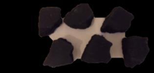

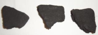


23 Traditional Random coal bed option: First identify the parts please see below: 7 X COAL A 3 X COAL B 2 X COAL C 2 X COAL D 2 X COAL E 23


24 Place the Random Coal Front matrix in place, insuring that it does not touch the pilot assembly behind. Place 5 A Coals between the front matrix and the rear matrix as shown do not block the area between the coal supports. Place the three large coals B as shown again ensuring that the area between the coal supports is clear. 24


25 Place the two coals C in the spaces left between Coals B. Now place the coals D in the top corners as shown below. Place the final two A coals between coals D Finally place the two small coals E between the A coals at the front on either side and coals B. 25

26 SECTION 9: FITTING THE DECORATIVE FRAME The appliance is supplied with a decorative frame, the frame attaches to the firebox as a three piece or one piece clip-on unit. Place the magnets supplied to the outer frame of the fire box. A plastic protective coating may be applied to the face of the frame assembly, which should be removed at this stage; the one piece unit can be placed in position. With the three piece unit you should start with the side pieces of the clip-on assembly, these should be pushed into position first, followed by the top bar, which should overlap the sides. IMPORTANT NOTE: Due to the possibility of sharp edges, care should be taken when handling the three piece frame components, the use of protective gloves is recommended. Place the fire front/ fret into position in front of the fire and slide the ashpan door into place. The fire front/fret shown in these instructions may differ from the one supplied with the appliance, we strongly recommend you use a fire front/fret supplied by Sirocco fires as these products will have been tested with the appliance, although other fire front/frets will be compatible. 26
27 Section 10: COMMISSIONING THE APPLIANCE Turn on and test the gas supply up to the fire for any leaks, in accordance with current Approved Codes of Practice (ACOPs) Section 10.1: OPERATING THE APPLIANCE (See User Instructions Section 18) Section 10.2: SPARK FAILURE The gap between the spark electrode and the pilot should be mm to produce a good spark. There should be no need to adjust this. If under any circumstances the electric spark fails, the pilot may be lit manually by proceeding with the ignition sequence as previously described, and after turning the control knob through the spark position, the knob should be held in and the pilot lit with a taper. Note: Please ensure that the electrode spark igniters gap on the manual version has not been misaligned during the handling of the burner in this installation the gap should be 5mm from the burner. 27
 Light the pilot and check the correct operation of the burner at all the flame settings.")
28 SECTION 11: SETTING PRESSURE Remove the pressure test point sealing screw from the isolation elbow and attach a suitable pressure gauge. Check that the inlet gas pressure is at 20 mbar Working Pressure at 20 Mbar (+/- 1 mbar) Light the pilot and check the correct operation of the burner at all the flame settings. Refer to the Operating instructions section 10.1 Check that the inlet gas pressure is at 20 mbar (+/- 1 mbar), when the fire is at its highest setting. Once the fire has been lit for 5 minutes, turn the gas OFF at the isolating elbow. After a further 3 minutes turn the gas supply ON again, if the gas has stopped flowing, the Flame Supervision Device (FSD) is operating correctly. Always check that the gas has stopped flowing even if you hear the FSD valve close within the 3-minute period. Turn OFF the appliance and the gas supply and refit the pressure test point sealing screw. 28
29 SECTION 12: FLUE SPILLAGE MONITORING SYSTEM Slide controlled fires are fitted with a flue spillage safety device (ODS). If the fire shuts down during use for no apparent reason then several things may be suspected, if a door or window has been opened creating a draught, then pilot disturbance is the problem, and removal of the draught should resolve this. The gas pressure reaching the fire must also be checked (again, recalls your installer to check and rectify any problem). The thermocouple connection into the back of the gas control valve may also have worked loose during installation, simply get the installer to tighten. If pilot disturbance is not the cause, then the ODS safety system may be in operation. Switch the appliance OFF, check the flue and carry out any remedial work required. Relight the fire and carry out a spillage test, DO NOT allow the appliance to be used if it continues to fail a spillage test. The aeration hole of the pilot must be carefully cleaned out on each annual service to ensure continued function of the ODS. The spillage monitoring system shall not be adjusted, modified, or put out of operation by the installer. Any spare parts fitted MUST be of a type supplied for the purpose by the appliance manufacturer. If the fire is not spilling, then further guidance should be sought, using the Troubleshooting section as a guide. SECTION 13: TESTING FOR SPILLAGE Close all doors and windows to the room containing the appliance. Let the fire run on HIGH for five minutes. Take a smoke match, light it, and using a smoke match tube, hold it at the top edge of the fire opening, 25mm down and 25mm in. Run the smoke match across the opening, all the smoke should be drawn away up the flue. Any smoke returning into the room indicates that spillage is occurring. If the initial spillage test fails, run the fire for a further 10 minutes and repeat the test. If the flue system is class 1 and the pull is strong you may wish to fit the spigot restrictor to maintain efficiency and to eliminate flame lifting off the burner, repeat spillage test to ensure all products of combustion are expelled, NEVER FIT TO PRECAST FLUES. 29


30 First bend the spigot plate to approximately 70 The flue spigot restrictor is fixed into place with two screws from the front of the fire SCREWS Please Note: If using the Super Convector firebox and the spillage test fails please remove the spigot restrictor making sure to replace the screws back in to their Please Note: If using the Super Convector firebox and the spillage test fails please remove the spigot restrictor making sure to replace the screws back in to their positions and re-test. When the test has been completed satisfactorily, repeat with any extractor fans in the premises running on the highest setting, and any communicating doors open, Finally, repeat with all doors open, DO NOT allows the fire to be used until the test is satisfactorily passed. 30
31 SECTION 14: BRIEFING THE CUSTOMER All instructions must be handed to the user for safekeeping. Show the customer how to light and operate the fire. After commissioning the appliance, the customer should be instructed on the safe use of the appliance and the informed for the need of regular servicing. Frequency of service depends on usage, but MUST be carried out at least once annually. Cleaning of the fire may be achieved when the fire is cold using a damp cloth and mild detergent on most surfaces, with the exception of the ceramic fuel bed. A soft brush i.e. paint brush may be used to clean the ceramic fuel bed taken care not to use excessive pressure. Scratched and other superficial damage to the matt black paintwork of the appliance can be covered with matching heatproof spray. Use only the manufacturers recommended spray paint. Paint only when the fire is OFF and cold. Always mask off the surrounding area to prevent contamination with overspray. Ventilate the room during the use of the spray. DO NOT attempt to spray paint the coals or ceramics, or wash them in water. Advise that the fire will emit a newness smell for a time after initial commissioning and that extra ventilation may be needed during this time. Advise that the fire is fitted with a spillage safety device (O.D.S.). If the fire shuts down, this system may be in operation. If spillage is suspected, SWITCH APPLIANCE OFF and call in the installer to investigate any problems SECTION 15: SERVICING First Isolate the fire from the gas supply and ensure that the fire is fully cold before attempting service. Lay out the dust sheet and tools required. Remove the cast front fret. Carefully remove the ceramic components Remove the two screws that retain the tray in place and disconnect from the isolation tap. Remove the burner tray and other components as required (i.e. remote control box) Disconnect the gas supply, to the appliance and disconnect the isolation tap Remove convector box by, firstly protecting the hearth from potential damage, unroll the coiled tensioner cables from the rear of the firebox, remove the securing nipples and tensioner adjusters, the firebox is now released from the opening and can be slid outward onto the hearth. Check the fireplace opening for rubble accumulation and remove, if debris is excessive, initiate remedial work on the flue. Check the flue with smoke pellet for correct operation. Refit convector box using new seals where necessary Strip off the burner pipes and clean thoroughly. Clean out the injector, pilot assembly and burner tube. DO NOT remove the pilot injector. Re-assemble and re-fit the burner tray. Turn on the gas supply, and leak test. Refit the decorative casting and ceramics. Check any purpose provided ventilation is un-obstructed. Light the fire and test for spillage. 31
32 SECTION 16: CLEANING THE COALS Remove the fire front/fret casting and place to one side. Remove the ceramic components. Gently clean in the open air using a dry paint brush. Be careful not to create dust from the coals. Where necessary replace damaged components with genuine spares. Seal scrap ceramic components in plastic bags and dispose at proper refuse sites as directed. Re-fit the coals by referring to the relevant sections of these instructions. SECTION 17: TROUBLESHOOTING GUIDE Manual and Slide Fire sparks but pilot Flame does not light? No gas to fire, check isolating valves are open. Pipe work blockage, clean out. Air not fully purged, re-purge supply or wait longer. Spark earthen to metal work, reset gap correctly. Blocked pilot, clean out internally. A pilot light but then goes out before main burner lights? Severe restriction in gas supply, clear obstruction. Faulty thermocouple, replace pilot unit. Hold control knob in for longer. Run through lighting system on the remote control several times allowing the valve to rest each time. Fire does not spark at pilot? HT lead detached, refit. Spark gap too large or small reset correctly. Spark shorting to metalwork under tray, re-align HT lead Fire runs for a time and then cuts off? Pilot flame shrinks when fire is on high? Fire smells when first lit or in use? Excessive room draught or flue pull, rectify. Loose or faulty thermocouple, rectify. O.D.S system in operation. Firebox grommet seal not fitted, rectify. Lint in pilot aeration hole, clean thoroughly internally Poor gas flow to fire, check pressure with fire on high. If pressure is low, remove any restriction in pipe work or valve. Check all isolators are adequately sized and fully open. Check meter pressure is adequate. Air leak under base of firebox, rectify. Lint in pilot aeration hole, clean thoroughly internally. Firebox grommet seal missing, rectify Newness smell from brand new appliance. Spillage occurring, call installer to carry out spillage test and rectify any problems. Low temperature sealants or combustible materials used in incorrect positions. Air leak under 32 base of firebox, rectify Firebox grommet seal missing rectify.
33 SECTION 18: USER INSTRUCTIONS IMPORTANT NOTES The installation of this fire MUST only be carried out by a competent person (such as a Gas Safe registered fitter) in accordance with the Gas Safety (Installation and Use) Regulations 1998, the relevant British Standards, Codes of Practice, the Building Regulations and the manufacturers instructions. Failure to comply with the above recommendations could lead to prosecution and invalidate the appliance warranty. Please ensure you are handed all of the manufacturer s documents on completion of the installation. This will include these instructions. Always keep a note of the installer s name and address, the original purchase receipt and the date of installation for future reference. The fire and flue should be serviced regularly to ensure continued safe operation. See the servicing section for further details. Frequency of service will depend on use, but MUST be carried out at least once annually. Parts of this appliance become naturally hot during use. It is recommended that a suitable fire guard conforming to BS 6778 is used, especially where young children, the elderly, or infirm are concerned. Combustible items, such as flooring and furniture, and soft wall coverings (such as blown vinyl or embossed paper) may discolour if fitted too close to the fire. See relevant section for further details on clearances to combustibles. No combustible material or flooring should protrude onto the hearth. DO NOT burn any foreign material on this fire, the coals must be of the correct type and lay out in accordance with the relevant section of these instructions. Failure to do so could create a hazard or lead to sooting. Before the appliance is installed, the chimney should be swept. All flues should be checked by the installer to ensure there are no defects or obstructions that may prevent the flow of combustion products. The fire is only suitable for use with the gas type for which it is supplied. This fire is supplied with a particular style of fire front/fret. Use of the fire front/fret will ensure an adequate airflow under the fire bed for the correct functioning of this appliance. Compliance with safety standards cannot be guaranteed if another style of front is used. A combustible shelf may be fixed to the wall above the fire, providing that it complies with the dimensions given in section 3 site requirements. No purpose provided ventilation is normally required for this appliance. The requirements of other appliances operating in the same space or room, and the results of a spillage test must be taken into consideration when assessing ventilation requirements; this will have been carried out by your Gas Safe registered installer. For Republic of Ireland, ventilation may be required, see IS 813, ICP3, IS 327, and any other rules in for 33
34 OPERATING THE APPLIANCE (Manual Control) For your safety, the fire is fitted with a Flame Supervision Device (FSD), which will shut off the Gas supply if for any reason the pilot is extinguished. This device incorporates a fixed probe, which senses heat from the pilot burner flame, if the probe is cooled, the device will prevent any gas flow. If for any reason the flames go out or if the fire has been turned off for any reason, always WAIT FOR 3 MINUTES before attempting to re-light. The pilot is visible through the Fuel bed at the front of the fire; rotate the coals for good viewing. Push in and turn the control knob to the SPARK position, and hold there for a few seconds. Continue turning anti-clockwise through the spark click to the PILOT light position, ensuring that the control knob is depressed and the pilot has lit. If not, return the knob clockwise, and repeat. OFF IGNITION LOW HIGH When the pilot lights after the spark, keep the knob depressed for approximately ten to fifteen seconds. Now release the knob and the pilot should stay alight. If the pilot is extinguished during use, wait three minutes before repeating the ignition procedure. To achieve the HIGH setting, push the control knob in slightly and continue turning anti-clockwise to the high position. The main burner should light after a few seconds, to decrease the setting to LOW, turn the control knob clockwise to the low setting. To turn to the PILOT position from the HIGH or LOW positions, press the control knob in, and return to the pilot position and release. To turn the fire OFF, keep the control knob depressed, and return to the off position and release. 34


35 OPERATING THE APPLIANCE (Slide control) For your safety, the fire is fitted with a Flame Supervision Device (FSD), which will shut off the Gas supply if for any reason the pilot is extinguished. Fit the 9V battery in to the battery lead at the left hand side of the fire. This device incorporates a fixed probe, which senses heat from the pilot burner flame, if the probe is cooled, the device will prevent any gas flow. If for any reason the flames go out or if the fire has been turned off for any reason, always WAIT FOR 3 MINUTES before attempting to re-light. The pilot is visible through the Fuel bed at the front of the fire; rotate the coals for good viewing 1. From the standing position push the thumb control all the way to the bottom where a spark will be heard and generated, hold down for approximately 15 seconds. 2. Release the pressure and the pilot light should now be established (if this fails repeat step 1 and hold down for 20 seconds). 3. Slide the control upwards to increase the flame size to the desired effect. 4. To switch the fire off simple slide the control upwards, passed the positive stop and hold for 2 seconds. 35
36 CLEANING Before carrying out any of the following operations, ensure that the fire is OFF and completely cold. Debris that may form on the fire bed should be periodically removed by a competent person. Large deposits could indicate deterioration of the flue. This should be repaired by a competent person, and the fire serviced before further use. FIRE FRONT/FRET - Any dust accumulating in the fire front may be removed using a vacuum cleaner or dry cloth. Heavy stains may be removed by using a damp cloth and mild household detergent. Brass parts of the fire front may be cleaned using a suitable brass cleaner. Replace the front centrally against the fire after cleaning. PAINTED AREAS - These can be cleaned using a dry cloth. COALS AND CERAMICS See the relevant section in the Installation Guide of these instructions. SERVICING The fire and flue should be checked on an annual basis to ensure all of the products of combustion are entering the flue and that there is no excessive build up of soot. The frequency of service will depend on usage, but MUST be carried out at least once annually. Servicing must be carried out by a competent person, such as a Gas Safe registered installer. Cleaning of the coals may be carried out by following the instructions given in the Installation section. The Installation instructions carry full servicing details for the use of the installer. If debris from the flue or other foreign matter is found on the fire it may indicate a need for servicing. Do not use the fire until the source of the debris has been found and rectified. Air vents (where fitted) should be checked periodically to ensure they are free from obstruction. 36
37 SECTION 19: WARRANTY IMPORTANT INFORMATION ABOUT WARRANTY SERVICE FOR THE END USER WARRANTY REGISTRATION IS REQUIRED WITHIN 28 DAYS FROM DATE OF PURCHASE It is in your interest to register your appliance with Sirocco as soon as possible BEFORE CONTACTING SIROCCO FOR SERVICE PLEASE READ THE FOLLOWING; Sirocco is committed to customer care and service. To ensure we provide the best service we can we have a policy to charge for all none warranty home visits so that all customers with a genuine manufactures fault can be dealt with swiftly, if your appliance has recently been installed and you are experiencing any of the following; Fumes are spilling from the flue/fire The pilot light cuts out after a few minutes The fire controls are getting too hot Excessive sooting is forming on the fuel bed Poor flame picture Remote controls are not working These symptoms tend to be chimney/flue or installations related and as such mostly are not covered by your warranty and are mostly dealt with in the installation instructions, DO NOT USE YOUR APPLIANCE and in the first instance contact your installer to investigate these further, to establish their cause before contacting Sirocco. CONTACTING SIROCCO FOR WARRANTY SERVICE OR TO PURCHASE SPARE PARTS In the event of a service or parts claim please note that some parts such as ceramics, batteries, trims and fronts etc are categorized as user serviceable parts and are not carried out by a service visit. Please ensure you have the following information at hand when you contact Sirocco; The full serial number which is located on the data badge of the appliance Your receipt of purchase showing the date and where purchased from Your installers details You can contact Sirocco`s representative in the UK by phone to obtain advice and a warranty service form on; Or you can complete a form on line at follow the link at the top right hand side on the home page. SIROCCO Sp. Zo.o Nad Lasem 8, Zelecow, Zabia Wola, Poland. Tel , Fax Further information, contact details and facilities are available through our website; 37


38 SECTION 20: LIST OF SPARES Eco 2 Manual Control 13/14B 11B 1B 7B/8B 2B 9B/10B 6B 15B 38


39 Eco 2 Manual Control 1D 2D 5D 9D 8D 3D 4D 7D 11D 3B 13D 2D 10D 39


40 Eco2 Ceramics 1A 2A 4A 40


41 Eco2 Ceramics 10A 41
42 code SPARE PART DESCRIPTION PART NUMBER 1A FRONT MATRIX E2 PRT CER MX/F ECO 2.3 BLK 2A REAR MATRIX E2 black PRT CER MX/RE ECO 2.3 BLK 3A REAR MATRIX E2 grey PRT CER MX/RE ECO 2.3 GRY 4A COAL SET E2.3 (14 PCS) PRT CER CO ECO 2.3 BLK 5A PEBBLE SET E2.3 (granite grey 14 pc) PRT CER PB ECO GRY 8A BACK BOARD ECO 2 PRT CER BB ECO 2 BLK 10A RANDOM COAL SET PRT CER FC R E 2 BLK 1B SPARK ELECTRODE INC FIXING SCREW PRT VAL SP UN M IS 0 2B THERMOCOUPLE INC LOCK NUT PRT VAL TP UN M CO 0 3B ISOLATION/PRESSURE TEST POINT VALVE INC NUT & OLIVE PRT VAL IS UNI 0 PR 0 FIXING KIT PRT FIX FK E1-5 0 SI 0 INSTALLATION & USER MANUAL ALL MODELS PRT DOC IM ECO 1 SI 1M 6B CONTROL VALVE KNOB (PACK X 2) PRT VAL KN UNI 0 POL 15 7B CONTROL VALVE (NATURAL GAS) PRT VAL CV ECO NG CO M 9B INJECTOR (NATURAL GAS) PRT VAL IJ ECO 2.3 BRA B BURNER (NATURAL GAS) PRT VAL BR E2 NG AE 41M 13B ENGINE NATURAL GAS (MANUAL) EXCLUDING CERAMICS PRT ECO 2 N M ENGINE 15B GAS INLET TUBE PRT VAL TU ECO 1-5- SI 1 TRIM 3 PART BRASS PRT DCF TR ECO 3PR SK BR TRIM 3 PART CHROME PRT DCF TR ECO 3PR SK CH 1D ENGINE (SLIDE) EXCLUDING CERAMICS PRT ECO 2 N SL E - 0 2D SLIDE CONTROL MECHANISM ASSEMBLY C/W LINKAGE PRT VAL SL UN MC SI 1 3D PILOT GAS TUBE 4MM complete with nuts & olives PRT VAL TU PI SL SI 2 4D GAS INLET TUBE 8MM complete with nuts & olives PRT VAL TU IN SL SI 1 PILOT NG Thermaco NG OXP-PG PRT VAL PI RO PL Therm 0 5D 7D GAS INLET TUBE 8MM C/W INLET ELBOW, NUTS & OLIVES PRT VAL TU IN SL SI 2 8D INJECTOR (NATURAL GAS) PRT VAL IJ ECO 2.3 BRA 480 9D BURNER (NATURAL GAS) FOR SLIDE CONTROL PRT VAL BR E2 NG AE 1 10D H T LEADS X3 for spark generator PRT VAL SL UN NG SI 1 11D SPARK GENERATOR PRT VAL SG UN NG TC 1 13D TEDDINGTON VALVE 3173/011 PRT VAL SL UN 0 TED 1 42
43 SECTION 21: CONTACT DETAILS GENERAL HELP LINE Mon to Fri 9:00 to 16:00 SPARE PARTS If you need assistance or wish to purchase spare parts Mon to Fri 9:00 to 16:00 Contact our spares department by Purchase spare parts direct from our website Spare parts are managed by our UK partner company Lodestar-Delta Ltd Lodestar-Delta Ltd T/A Sirocco Unit 1, 11 Weir St, Blackburn, Lancashire BB2 2AN SIROCCO HEAD OFFICE Telephone number for all departments (charged at BT national rate) Mon to Fri 10:00 to 15:00 Contact us by View our latest products and use our on line services; Nad Lasem 8, Zabia Wola Zelechow Poland WARRANTY AND SERVICE For warranty registration or for a home service call: For assistance to complete a registration or a home service Call us on Mon to Fri 9:00 to 16:00 43
44 Our warranty statement 5 YEAR WARRANTY STATEMENT You have purchased your new Sirocco appliance that has been made to the highest standards. When properly maintained and used the appliance will perform perfectly for many years, and is warranted for 12 months from date of purchase for parts and labour as covered by the terms and conditions of warranty, verification may be required of the defect by a Sirocco engineer, or a Sirocco appointed engineer, provided that such parts have been subjected to normal conditions of use. In addition there is a further 4 year parts only warranty available at no extra cost; this is limited to the repair or replacement of parts found to be defective. To qualify please ensure the appliance is serviced every year as required by law and that a service kit is used which is available direct from Sirocco Registration of guarantee and Sirocco Sp. zo.o has a commitment to quality as regards customer care and service and therefore it is important that you and your installer complete your warranty form completely and correctly and return it to us within 28 days of date of purchase. Alternatively you can complete the form on line at and follow the link on the home page headed guarantee registration. In addition a gas safety certificate must be issued by the installer and you are required by law to register the appliance within 30 working days with the local authority building control and you will find this information to assist you on the same location as the guarantee registration. This guarantee applies to gas fires only, electrical appliances are not included. By registering you will assist us in identifying the correct parts you may require in the future, or ensuring that the correct parts are given to an engineer for a service visit. Please ensure you provide this to us within 28 days stated, and include the Gas Safe notification number or your warranty will not be valid. Regular Servicing It is essential that your Sirocco appliance is serviced, by a suitably qualified Gas Safe engineer or a Sirocco authorised appointed engineer to carry this out at least within each twelve month period as required by law, and to qualify for your 5 year warranty. It should be noted that that each appliance has different requirements for parts to be replaced at a service and you should consult and purchase the service packs form the sirocco website relevant to each model and service interval as part of the conditions of your 5 year warranty Contacting Sirocco If you need to contact Sirocco for a Warranty service or to purchase spare parts the contact details and procedure are printed on the back page of your installation/user guide What else should I know? The following is an extract from the full terms and conditions for warranty which are located in your instruction/user guide and on the Sirocco website. The following are not covered by warranty: paint work in the fire chamber, fire fronts, and decorative trims, crazing of ceramic components, and marks or clouding on glass, batteries, electronic or electric/mechanical components such as remote controls. The warranty is only valid if registered within 28 days of purchase providing all the information stated (proof of purchase will be required and a gas safety certificate must be issued by the engineer on installation and with every service) registration with the local authority via Gas Safe is mandatory and is only for a UK domestic installation, provided the appliance has been installed in accordance to the installation instructions and in compliance with current regulations in a correctly functioning flue. Validation of your installation will be required prior to warranty 44


45 service/repair; there will be a fee for this. No other validation will be accepted by Sirocco. Accidental damage or improper use is not covered by warranty. This guarantee is non-transferable and is made to the original owner provided that the purchase was made through an approved Sirocco Fires stockist This guarantee is none transferable and is made to the original owner, provided that the purchase was made through an company appointed stockist Any installation, labour, transportation or other related costs expenses arising from defective parts repair replacement or otherwise of same will not be covered by this guarantee nor shall the company assume responsibility for same. Furthermore the company will not be responsible for any incidental, indirect or consequential damages except as provided by law. All other guarantees expressed or implied with respect to the product, it s components and accessories or any obligations or liabilities on the part of Sirocco Fires are hereby expressly excluded. Sirocco Fires neither assumes nor authorises any third party to assume on it s behalf, any other liabilities with respect to the sale of this Sirocco Fire appliance. Location of your serial number, this will be on the data badge on the appliance which will look something like this and will be located under the fire or behind the fascia. For full terms and conditions of warranty please refer to our website 45
Model Apex Falcon, Titan & Zenit
 Model Apex Falcon, Titan & Zenit Installation and User Instructions All instructions must be handed to user for safekeeping This is not a DIY product and must be installed by a Gas Safe registered installer
Apex. Adara HE. Installation and User Instructions
 Apex Adara HE Installation and User Instructions All instructions must be handed to user for safekeeping This is not a DIY product and must be installed by a Gas Safe registered installer Edition D 09/15
Model Apex Adara Slimline HE
 Model Apex Adara Slimline HE Manual Control Installation and User Instructions All instructions must be handed to user for safekeeping This is not a DIY product and must be installed by a Gas Safe registered
Model Eco4 HE. Model options. E4 HE Plus, E4 HE Nova, Extra HE
 Model Eco4 HE Model options E4 HE Plus, E4 HE Nova, Extra HE Apex, Blenheim, Cristal, Grace, Daisy, Soho, Contemporary, Contemporary II, Ignite, Fairfield, Magma HE, SP200, MX20, Pinnacle Slimline HE,
INSTALLATION & USER INSTRUCTIONS INSET DECORATIVE GAS FIRE
 INSTALLATION & USER INSTRUCTIONS INSET DECORATIVE GAS FIRE MODELS COVERED BY THESE INSTRUCTIONS HANNINGTON BRASS F500310 HANNINGTON BLACK F500311 Focal Point Fires plc. Christchurch, Dorset BH23 2BT Tel:
Apex. Model Options Liberty 6 & 10. Information & Installation Guide
 Apex Model Options Liberty 6 & 10 Information & Installation Guide This is not a DIY product and must be installed by a Gas Safe registered installer The information contained herein is not meant to replace
ARIES AURA BLENHEIM STYLE
 ARIES AURA BLENHEIM STYLE FULL DEPTH GAS FIRE INSTALLATION AND USER INSTRUCTIONS All instructions must be handed to user for safekeeping Revision A - 05/05 Country(s) of destination - GB/IE Focal Point
NIGMA. Fuel Effect Gas Fire INSTALLATION, SERVICING AND USER INSTRUCTIONS. All instructions must be handed to the user for safekeeping
 Σ NIGMA Fuel Effect Gas Fire INSTALLATION, SERVICING AND USER INSTRUCTIONS All instructions must be handed to the user for safekeeping Revision A 09/03 Country(s) of destination: GB, IE Focal Point Fires
SLIMLINE RADIANT GAS FIRE
 SLIMLINE RADIANT GAS FIRE FOR USE WITH CHLOE - JULIET - NEW WAVE - HEAT WAVE ANNABELLE - ZARA - CARMEN - CARMEN HIW INSTALLATION AND USER INSTRUCTIONS All instructions must be handed to user for safekeeping
installation and user instructions
 installation and user instructions All instructions must be handed to user for safekeeping Revision A - 08/09 Country(s) of destination - GB/IE eko 4010 eko 400 high efficiency fuel effect gas fire Eko
installation and user instructions
 installation and user instructions All instructions must be handed to user for safekeeping Revision A - 06/09 Country(s) of destination - GB/IE eko 3030 eko 3035 eko 3040 eko 3050 eko 3060 eko 3065 fuel
installation and user instructions
 installation and user instructions All instructions must be handed to user for safekeeping Revision A - 06/09 Country(s) of destination - GB/IE eko 010 - eko 020 fuel effect gas fire manual - remote control
INSTALLATION & USER INSTRUCTIONS FULL DEPTH RADIANT/CONVECTOR INSET GAS FIRE
 INSTALLATION & USER INSTRUCTIONS FULL DEPTH RADIANT/CONVECTOR INSET GAS FIRE MODELS COVERED BY THESE INSTRUCTIONS GB IE ELYSEE RADIANT F500007 Focal Point Fires plc. Christchurch, Dorset BH23 2BT Tel:
INSTALLATION & USER INSTRUCTIONS
 INSTALLATION & USER INSTRUCTIONS STONE EFFECT DECORATIVE GAS FIRE MODELS COVERED BY THESE INSTRUCTIONS POLARIS GB IE Focal Point Fires plc. Christchurch, Dorset BH23 2BT Tel: 01202 499330 Fax: 01202 499326
installation and user instructions
 installation and user instructions All instructions must be handed to user for safekeeping Revision A - 06/09 Country(s) of destination - GB/IE eko 00 fuel effect gas fire INSTALLATION INSTRUCTIONS Preliminary
INSTALLATION & USER INSTRUCTIONS
 INSTALLATION & USER INSTRUCTIONS FULL DEPTH RADIANT & CONVECTOR GAS FIRES Focal Point Fires plc. Christchurch, Dorset BH23 2BT Tel: 01202 499330 Fax: 01202 499326 www.focalpointfires.co.uk e : sales@focalpointfires.co.uk
(manual control) (ezi-slide control) INSET COAL EFFECT GAS CONVECTOR FIRE V1/100/B INSTALLATION & USER INSTRUCTIONS
 (ezi-slide control) INSET COAL EFFECT GAS CONVECTOR FIRE V1/100/B INSTALLATION & USER INSTRUCTIONS") Model Number: V1/100/A V1/100/B (manual control) (ezi-slide control) INSET COAL EFFECT GAS CONVECTOR FIRE INSTALLATION & USER INSTRUCTIONS GB IE SUITABLE FOR USE ON NATURAL GAS (G20) AT 20mbar SUPPLY PRESSURE
Model Number: V1/100/A V1/100/B (manual control) (ezi-slide control) INSET COAL EFFECT GAS CONVECTOR FIRE INSTALLATION & USER INSTRUCTIONS GB IE SUITABLE FOR USE ON NATURAL GAS (G20) AT 20mbar SUPPLY PRESSURE
INSTALLATION & USER INSTRUCTIONS
 INSTALLATION & USER INSTRUCTIONS HIGH EFFICIENCY GAS FIRE MODELS COVERED BY THESE INSTRUCTIONS BLENHEIM HE GAS FIRE HORIZON HE GAS FIRE LULWORTH HE GAS FIRE Focal Point Fires plc. Christchurch, Dorset
OWNER S GUIDE ETERNITY. MODEL 540C (GC No ) INSET BALANCED FLUE GAS FIRE
 INSET BALANCED FLUE GAS FIRE") 600B637/02 ETERNITY MODEL 540C (GC No. 32-032-19) INSET BALANCED FLUE GAS FIRE THIS APPLIANCE IS FOR USE WITH NATURAL GAS (G20) THIS APPLIANCE IS FOR USE IN THE UNITED KINGDOM (GB) AND THE REPUBLIC OF
600B637/02 ETERNITY MODEL 540C (GC No. 32-032-19) INSET BALANCED FLUE GAS FIRE THIS APPLIANCE IS FOR USE WITH NATURAL GAS (G20) THIS APPLIANCE IS FOR USE IN THE UNITED KINGDOM (GB) AND THE REPUBLIC OF
Kalahari DECORATIVE FUEL EFFECT GAS FIRE
 Kalahari DECORATIVE FUEL EFFECT GAS FIRE User Instructions These instructions should be read by the user before operating the appliance and retained for future reference Model No. KRDC00MN & KRDC00SN are
EMBERGLOW CLASSIC RADIANT CONVECTOR GAS FIRE. Installation and Maintenance Instructions
 , EMBERGLOW CLASSIC RADIANT CONVECTOR GAS FIRE Installation and Maintenance Instructions Hand these instructions to the user Model No. FEMC00MN is for use on Natural Gas (G20) at a supply pressure of 20
INSTALLATION & USER INSTRUCTIONS
 INSTALLATION & USER INSTRUCTIONS INSET DECORATIVE GAS FIRE MODELS COVERED BY THESE INSTRUCTIONS eko 2050 Christchurch, Dorset BH23 2BT Tel: 01202 588 638 Fax: 01202 499 639 www.ekofires.co.uk e-mail: sales@ekofires.co.uk
OWNER GUIDE. Model 739 OPEN DECORATIVE GAS FIRE. (GC No )
") 5113426/01 OWNER GUIDE Model 739 OPEN DECORATIVE GAS FIRE (GC No. 32-032-54) THIS APPLIANCE IS FOR USE WITH NATURAL GAS (G20). WHEN CONVERTED USING CONVERSION KIT NO. 0595211 THIS APPLIANCE IS FOR USE
5113426/01 OWNER GUIDE Model 739 OPEN DECORATIVE GAS FIRE (GC No. 32-032-54) THIS APPLIANCE IS FOR USE WITH NATURAL GAS (G20). WHEN CONVERTED USING CONVERSION KIT NO. 0595211 THIS APPLIANCE IS FOR USE
Dovre 250 Cast Iron Gas Stove
 Dovre 50 Cast Iron Gas Stove NATURAL GAS AND LPG INSTALLATION, SERVICING AND USER INSTRUCTIONS THIS PRODUCT IS FOR USE ONLY IN GREAT BRITAIN AND IRELAND These instructions are to be left with the customer,
INSTALLATION & USER INSTRUCTIONS
 INSTALLATION & USER INSTRUCTIONS MULTIFLUE/INSET GAS FIRE Pure Glow Limited Stour Vale Road Lye, Stourbridge West Midlands DY9 8PP t: 01384 893060 f: 01384 897728 www.pureglowltd.co.uk email: info@pureglowltd.co.uk
INSTALLATION & USERS INSTRUCTIONS. FOR USE WITH NATURAL GAS 20 mbar For use in GB and IE
 1 valentine s buildings Bechers drive Aintree racecourse Business Park L9 5ay CF1 L GAS APPLIANCE INSET CONVENTIONAL FLUED GAS FIRE INSTALLATION & USERS INSTRUCTIONS FOR USE WITH NATURAL GAS G20 @ 20 mbar
GB IE INSTALLATION & USER INSTRUCTIONS. Model Number: V1/300/B (ez-slide control) HIGH EFFICIENCY INSET COAL EFFECT GAS CONVECTOR FIRE
 HIGH EFFICIENCY INSET COAL EFFECT GAS CONVECTOR FIRE") Model Number: V1/300/B (ez-slide control) HIGH EFFICIENCY INSET COAL EFFECT GAS CONVECTOR FIRE INSTALLATION & USER INSTRUCTIONS GB IE SUITABLE FOR USE ON NATURAL GAS (G20) AT 20mbar SUPPLY PRESSURE These
Model Number: V1/300/B (ez-slide control) HIGH EFFICIENCY INSET COAL EFFECT GAS CONVECTOR FIRE INSTALLATION & USER INSTRUCTIONS GB IE SUITABLE FOR USE ON NATURAL GAS (G20) AT 20mbar SUPPLY PRESSURE These
INSTALLATION INSTRUCTIONS COMPACT GAS STOVE MODEL NUMBER 550
 INSTALLATION INSTRUCTIONS COMPACT GAS STOVE MODEL NUMBER 550 Before installation ensure that the local distribution conditions (identification of the type of gas and pressure) and the adjustment of the
CRYSTAL FIRES. Inset Conventional Flue Fire. (BOSTON/MIAMI) Cf1 and MANHATTAN USER INSTALLATION AND SERVICING INSTRUCTIONS
 Cf1 and MANHATTAN USER INSTALLATION AND SERVICING INSTRUCTIONS") CRYSTAL FIRES (BOSTON/MIAMI) Cf1 and MANHATTAN Inset Conventional Flue Fire USER INSTALLATION AND SERVICING INSTRUCTIONS FOR USE WITH NATURAL GAS G20 @ 20 mbar For use in GB and IE CE THESE INSTRUCTIONS
CRYSTAL FIRES (BOSTON/MIAMI) Cf1 and MANHATTAN Inset Conventional Flue Fire USER INSTALLATION AND SERVICING INSTRUCTIONS FOR USE WITH NATURAL GAS G20 @ 20 mbar For use in GB and IE CE THESE INSTRUCTIONS
OWNER GUIDE. Anthem, Bolero, Camden, Minima, Victorian or Westminster fascia
 5114465/01 OWNER GUIDE Model 741 INSET LIVE FUEL EFFECT GAS FIRE Fitted with Anthem, Bolero, Camden, Minima, Victorian or Westminster fascia (GC No. 32-032-56) THIS APPLIANCE IS FOR USE WITH NATURAL GAS
ULTIMATE INSET LIVE FUEL EFFECT GAS FIRE MODEL 417 OWNER GUIDE
 ULTIMATE INSET LIVE FUEL EFFECT GAS FIRE MODEL 417 OWNER GUIDE THE NATURAL GAS MODEL IS FOR G20 AT A SUPPLY PRESSURE OF 20mbar THE PROPANE GAS MODEL IS FOR G31 AT A SUPPLY PRESSURE OF 37mbar THESE APPLIANCES
MODEL 466 Radiant / Convector Gas Fire Black Beauty
 I N S T A L L E R G U I D E MODEL 466 Radiant / Convector Gas Fire Black Beauty Please keep in a safe place for future reference 600A734/02 Please leave this Installer Guide with the user This appliance
INSTALLATION & USER INSTRUCTIONS
 INSTALLATION & USER INSTRUCTIONS MULTIFLUE/INSET GAS FIRE Focal Point Fires plc. Christchurch, Dorset BH23 2BT Tel: 01202 499330 Fax: 01202 499326 www.focalpointfires.co.uk e : sales@focalpointfires.co.uk
MODEL 466 Radiant / Convector Gas Fire Black Beauty
 O W N E R G U I D E MODEL 466 Radiant / Convector Gas Fire Black Beauty This Owner Guide is intended to help you care for your Valor gas fire. Please read carefully before using your gas fire and keep
Vola 600HE Vola 6x6HE
 Vola 600HE Vola 6x6HE Also known as Ignite Pinnacle 600 / Apex 600 Ignite Pinnacle 6x6 / Apex 6x6 Installation and User Instructions FRAMELESS AND INTEGRATED SUITE INSTRUCTION ARE SEPARATE AND MUST BE
GrateGlow THE ALL NEW CAPITAL COLLECTION. G20 at 20mbar convertible to G31 at 37mbar. For use in GB and le. Users Instructions
 GrateGlow A CARVER GROUP COMPANY --..--... THE GAS CONSUMERS' COUNCIL (GCC) IS AN INDEPENDENT ORGANISATION WHICH PROTECTS THE INTEREST OF GAS USERS. IF YOU NEED ADVICE, YOU WILL FIND THE TELEPHONE NUMBER
OWNER GUIDE. Model 750. INSET LIVE FUEL EFFECT GAS FIRE Fitted with Harmony, Avignon or Style fascia. (GC No )
") 5112499/01 OWNER GUIDE Model 750 INSET LIVE FUEL EFFECT GAS FIRE Fitted with Harmony, Avignon or Style fascia (GC No. 32-032-58) THIS APPLIANCE IS FOR USE WITH NATURAL GAS (G20) WHEN CONVERTED USING CONVERSION
5112499/01 OWNER GUIDE Model 750 INSET LIVE FUEL EFFECT GAS FIRE Fitted with Harmony, Avignon or Style fascia (GC No. 32-032-58) THIS APPLIANCE IS FOR USE WITH NATURAL GAS (G20) WHEN CONVERTED USING CONVERSION
INSET LIVE FUEL EFFECT GAS FIRE
 600B741/02 OWNER S GUIDE MODEL BR650 VA (GC No. 32-032-39) INSET LIVE FUEL EFFECT GAS FIRE THIS APPLIANCE IS FOR USE WITH NATURAL GAS (G20) WHEN CONVERTED USING CONVERSION KIT NO.591149 THIS APPLIANCE
Sonnet Plus Anthem Genesis Soraya
 5110524/01 OWNER GUIDE Sonnet Plus Anthem Genesis Soraya Model 747 (GC No. 32-032-51) INSET LIVE FUEL EFFECT GAS FIRE THIS APPLIANCE IS FOR USE WITH NATURAL GAS (G20) WHEN CONVERTED USING CONVERSION KIT
BLACK KNIGHT 2 - Classic Collection
 BLACK KNIGHT 2 - Classic Collection Installation & Servicing Instructions (GC No. 32 170 16) IMPORTANT - THIS FIRE DOES NOT NORMALLY REQUIRE ADDITIONAL VENTILATION INTO THE ROOM IN WHICH IT IS INSTALLED
Sonnet Plus Anthem Genesis Soraya
 5108617/01 OWNER GUIDE Sonnet Plus Anthem Genesis Soraya Model 746 (GC No. 32-032-57) INSET LIVE FUEL EFFECT GAS FIRE THIS APPLIANCE IS FOR USE WITH NATURAL GAS (G20) WHEN CONVERTED USING CONVERSION KIT
OWNER S GUIDE MODEL BR417 VA
 600B702/06 OWNER S GUIDE MODEL BR417 VA (G.C.32-032-07) Inset Live Fuel Effect Gas Fire with Ultimate Front AS SUPPLIED, THIS APPLIANCE IS FOR USE WITH NATURAL GAS (G20) WHEN CONVERTED USING VALOR CONVERSION
INSTALLATION, USERS AND SERVICING INSTRUCTIONS
 INSTALLATION, USERS AND SERVICING INSTRUCTIONS SLIMLINE (FAN FLUE) HOTBOX Inset Decorative coal or pebble effect Gas Fire For use with Natural Gas (G20) @ 20mbar or Butane (G30) @ 28mbar or Propane (G31)
5traxo INSTALLATION AND SERVICING INSTRUCTIONS MANDATORY REQUIREMENTS INSTALLATION
 5traxo Division of Legge Fabheat Ltd Longfield Road, Sydenham, Leamington Spa CV31 1XB Tel. (0926) 882233 Fax (0926) 450846 Registered in England No. 500091 Universal INSTALLATION AND SERVICING INSTRUCTIONS
AFINA FLUELESS GAS STOVE INSTALLATION AND USER INSTRUCTIONS
 AFINA FLUELESS GAS STOVE INSTALLATION AND USER INSTRUCTIONS All instructions must be handed to user for safekeeping Revision A - 08/05 Country(s) of destination - GB/IE CK Fires Ltd. 1 Stour House, Clifford
Emberglow COAL EFFECT BALANCED FLUE GAS FIRE
 Emberglow COAL EFFECT BALANCED FLUE GAS FIRE User Instructions These instructions should be read by the user before operating the appliance and retained for future reference Model No. FEBC00MN is only
FULL DEPTH HE GAS FIRE
 FULL DEPTH HE GAS FIRE USER INSTRUCTIONS INSTALLATION INSTRUCTIONS SERVICE INSTRUCTIONS It is a regulation that these instructions be handed to the customer after installation is complete. It is also the
Apex X2 HE Apex X3 HE
 Apex X2 HE Apex X3 HE Installation and User Instructions FRAMELESS AND INTEGRATED SUITE INSTRUCTION ARE SEPARATE AND MUST BE READ IN CONJUNCTION WITH THESE INSTRUCTIONS BEFORE INSTALLATION STARTS All instructions
APEX Cirrus X1. Installation and User Instructions
 APEX Cirrus X1 Installation and User Instructions All instructions must be handed to user for safekeeping This is not a DIY product and must be installed by a Gas Safe registered installer Edition H 10/15
Model BR660VA Heat Engine
 5112253/01 Model BR660VA Heat Engine POWER FLUE INSET GAS FIRE (GC No. 32-032-44) THIS APPLIANCE IS FOR USE WITH NATURAL GAS (G20). WHEN CONVERTED USING CONVERSION KIT NO. 0591149 THIS APPLIANCE IS FOR
CLASSIC II QUATTRO DECORATIVE FUEL EFFECT APPLIANCES FOR USE WITH NATURAL GAS IIN INSTALLATION, SERVICING & USER INSTRUCTIONS
 CLASSIC II QUATTRO DECORATIVE FUEL EFFECT APPLIANCES FOR USE WITH NATURAL GAS IIN INSTALLATION, SERVICING & USER INSTRUCTIONS THESE INSTRUCTIONS MUST BE LEFT WITH THE USER MANUFACTURED BY: MULTIGLOW FIRES
Integra Convector Plus Manual
 Integra Convector Plus Manual Inset Live Fuel Effect Gas Fire Installation and Users Instructions These instructions should be read by the installer before installation and then should be handed to the
Model 341 Black Beauty Slimline
 600B690/13 OWNER GUIDE Model 341 Black Beauty Slimline LIVE FUEL EFFECT GAS FIRE (GC No. 32-032-30) We trust that this guide gives sufficient details to enable this appliance to be operated and maintained
Kalahari RC & Camber RC
 Kalahari RC & Camber RC DECORATIVE FUEL EFFECT GAS FIRE User Instructions These instructions should be read by the user before operating the appliance and retained for future reference Model No s KRDC**RN
Owner s Manual INCLUDES. PARAGON 2016 & PARAGON 2016 Hi IMPORTANT
 Owner s Manual INCLUDES User, Maintenance, Service, and Installation Instructions PARAGON 2016 & PARAGON 2016 Hi Keep this booklet for service log and future reference IMPORTANT This appliance is guaranteed
ENIGMA II SLIMLINE. Owner's Manual INCLUDES USER, INSTALLATION & MAINTENANCE INSTRUCTIONS
 ENIGMA II SLIMLINE Owner's Manual INCLUDES USER, INSTALLATION & MAINTENANCE INSTRUCTIONS Please read these instructions carefully before you start using the appliance Keep this booklet handy for future
COAL EFFECT BALANCED FLUE GAS FIRE
 Raglan COAL EFFECT BALANCED FLUE GAS FIRE Installation and Maintenance Instructions Hand these instructions to the user Model No. KBFC**MN for use on Natural Gas (G20) at a supply pressure of 20 mbar in
THIS PRODUCT IS APPROVED TO THE EUROPEAN GAS APPLIANCE DIRECTIVE
 Solar Crown and Cast Inset Fires Installation Instructions THIS APPLIANCE MUST BE INSTALLED/SERVICED BY A COMPETENT PERSON IN ACCORDANCE WITH ALL THE REGULATIONS IN FORCE THIS PRODUCT IS APPROVED TO THE
PARAGON 2000 Xtra SLIDE CONTROL Owner's Book
 PARAGON 2000 Xtra SLIDE CONTROL Owner's Book INCLUDES USER, INSTALLATION & MAINTENANCE INSTRUCTIONS Please read these instructions carefully before you start using the appliance Keep this booklet handy
OWNER GUIDE. Sunfire II Radiant. Radiant / Convector Gas Fire. Model 347 (G. C. Number )
") 5110946/01 OWNER GUIDE Sunfire II Radiant Radiant / Convector Gas Fire Model 347 (G. C. Number 32-032-62) THIS APPLIANCE IS FOR USE WITH NATURAL GAS (G20) THIS APPLIANCE IS SUITABLE ONLY FOR INSTALLATION
5110946/01 OWNER GUIDE Sunfire II Radiant Radiant / Convector Gas Fire Model 347 (G. C. Number 32-032-62) THIS APPLIANCE IS FOR USE WITH NATURAL GAS (G20) THIS APPLIANCE IS SUITABLE ONLY FOR INSTALLATION
MODEL 326 Radiant / Convector Gas Fire Sun~Fire
 O W N E R G U I D E MODEL 326 Radiant / Convector Gas Fire Sun~Fire This Owner Guide is intended to help you care for your Valor gas fire. Please read carefully before using your gas fire and keep for
STRATA BATTERY IGNITION RADIANT CONVECTOR GAS FIRE
 STRATA BATTERY IGNITION RADIANT CONVECTOR GAS FIRE Installation, Maintenance & User Instructions Hand these instructions to the user Model No s FORS**EN are for use on Natural Gas (G20) at a supply pressure
Classic DECORATIVE FUEL EFFECT GAS FIRE. Installation, Maintenance & User Instructions
 Classic DECORATIVE FUEL EFFECT GAS FIRE Installation, Maintenance & User Instructions Hand these instructions to the user Model No s CSRC**MN is only for use on Natural Gas (G20) at a supply pressure of
Model 741FS. Dream, Heritage or Opulent OWNER GUIDE. INSTALLER: Please leave this guide with the owner Baxi Heating U.K. Limited 2007.
 5112500/02 Model 741FS Inset live fuel effect gas fire Incorporating the BAXI FIRES DIVISION CONTROL Fitted with one of the following fascia. Dream, Heritage or Opulent (GC No. 32-032-56) We trust that
ENIGMA II SLIDE CONTROL Owner's Book
 ENIGMA II SLIDE CONTROL Owner's Book INCLUDES USER, INSTALLATION & MAINTENANCE INSTRUCTIONS Please read these instructions carefully before you start using the appliance Keep this booklet handy for future
Model 347 BLACK BEAUTY
 110945/03 OWNER GUIDE Model 347 BLACK BEAUTY RADIANT / CONVECTOR GAS FIRE (G. C. No. 32-032-62) We trust that this guide gives sufficient details to enable this appliance to be operated and maintained
Orchestra COAL EFFECT BALANCED FLUE GAS FIRE
 Orchestra COAL EFFECT BALANCED FLUE GAS FIRE Installation and Maintenance Instructions Hand these instructions to the user Model No s FBFN76G & FBFN98G are for use on Natural Gas (G20) at a supply pressure
PARAGON FOCUS HE MULTI - FLUE SLIDE CONTROL
 PARAGON FOCUS HE MULTI - FLUE SLIDE CONTROL OWNER MANUAL INCLUDES USER INSTRUCTION & INSTALLATION & MAINTENANCE INSTRUCTIONS Please read these instructions carefully before you start installing or using
Installation & Service Instructions
 Part No. 966/9350/1 02 Potterton Housewarmer Illusion ASD - G.C. NO. 37 590 16 966 Inset DGF with ILLUSION FACIA Potterton Housewarmer Stratton ASD - G.C. NO. 37 590 17 966 Inset DGF with STRATTON FACIA
USE & MAINTENANCE INSTRUCTIONS FOR NU-FLAME EVOLUTION PLUS GAS EFFECT FIRES (NATURAL GAS & LPG) FOR DECORATIVE PURPOSES ONLY
 FOR DECORATIVE PURPOSES ONLY") Unit 4, Kimpton Trade & Business Centre Minden Road, Sutton, Surrey SM3 9PF Tel: 020 8254 6802 IMPORTANT NOTE Simulated coals, simulated pebbles, simulated logs, simulated driftwood or crushed rock manufactured
Unit 4, Kimpton Trade & Business Centre Minden Road, Sutton, Surrey SM3 9PF Tel: 020 8254 6802 IMPORTANT NOTE Simulated coals, simulated pebbles, simulated logs, simulated driftwood or crushed rock manufactured
Mesina Fires GLASS FRONT VENTED Model No. M 70
 Mesina Fires GLASS FRONT VENTED Model No. M 70 DECORATIVE COAL EFFECT NATURAL VENT GAS FIRE User Instructions These instructions should be read by the user before operating the appliance and retained for
Napoli BF COAL EFFECT BALANCED FLUE GAS FIRE
 Napoli BF COAL EFFECT BALANCED FLUE GAS FIRE Installation, Maintenance & User Instructions Hand these instructions to the user Model No. ABFC**MN2 & ABFC**EN3 are for use on Natural Gas (G20) at a supply
Conventional Flue. Instructions for Installation. For use in NZ (New Zealand). IMPORTANT
. IMPORTANT") Logic HE Range Conventional Flue Instructions for Installation For use in NZ (New Zealand). IMPORTANT INSTALLATION AND SERVICING MUST ONLY BE CARRIED OUT BY AUTHORISED PERSONNEL. THE OUTER CASING, FRONT
Logic HE Range Conventional Flue Instructions for Installation For use in NZ (New Zealand). IMPORTANT INSTALLATION AND SERVICING MUST ONLY BE CARRIED OUT BY AUTHORISED PERSONNEL. THE OUTER CASING, FRONT
INSTALLER S GUIDE. MODEL 639 Open Decorative Gas Fire
 3002369/03 INSTALLER S GUIDE MODEL 639 Open Decorative Gas Fire (G.C No. 32-032-47) THIS APPLIANCE IS FOR USE WITH NATURAL GAS (G20) WHEN CONVERTED USING CONVERSION KIT NO. 0591301 THIS APPLIANCE IS FOR
Plus Model BR645 VA (G.C )
") 600B656/05 Plus Model BR645 VA (G.C. 32-032-34) As supplied, this appliance is for use with natural gas (G20) When converted using conversion kit no. 591149 this appliance is for use with propane gas (G31)
600B656/05 Plus Model BR645 VA (G.C. 32-032-34) As supplied, this appliance is for use with natural gas (G20) When converted using conversion kit no. 591149 this appliance is for use with propane gas (G31)
L23 BLACK P23 CONTEMPORARY GLASS
 L23 BLACK P23 CONTEMPORARY GLASS FLUELESS GAS FIRE INSTALLATION AND USER INSTRUCTIONS All instructions must be handed to user for safekeeping Revision A - 03/08 Country(s) of destination - GB/IE Focal
Torch framed Installation Guide
 Torch framed 40010567-0602 Installation Guide 1 2 3 4 1 < < < < 5 6 7 > > > > 2 Content 1 Introduction... 1 2 Safety Instructions... 2 3 Installation requirements... 3 3.1 Rear surface construction...
INSTALLER GUIDE COALFLAME & LIMOUSIN. MODEL BR627 (GC No ) INSET LIVE FUEL EFFECT GAS FIRE
 INSET LIVE FUEL EFFECT GAS FIRE") 600B607/05 INSTALLER GUIDE COALFLAME & LIMOUSIN MODEL BR627 (GC No. 32-032-22) INSET LIVE FUEL EFFECT GAS FIRE AS SUPPLIED, THIS APPLIANCE IS FOR USE WITH NATURAL GAS (G20) WHEN CONVERTED USING VALOR CONVERSION
600B607/05 INSTALLER GUIDE COALFLAME & LIMOUSIN MODEL BR627 (GC No. 32-032-22) INSET LIVE FUEL EFFECT GAS FIRE AS SUPPLIED, THIS APPLIANCE IS FOR USE WITH NATURAL GAS (G20) WHEN CONVERTED USING VALOR CONVERSION
VFC Radiant & Convector
 VFC Radiant & Convector Fire Range With Upgradeable Control Valve Instructions for Use, Installation and Servicing For use in GB, IE (Great Britain and Republic of Ireland) IMPORTANT THIS PRODUCT HAS A
GB IE. VALOR BOLERO (MODEL BR626) Inset Decorative Fuel Effect Gas Fires. For
 Inset Decorative Fuel Effect Gas Fires. For") O W N E R G U I D E For VALOR BOLERO (MODEL BR626) Inset Decorative Fuel Effect Gas Fires GB IE This Owner Guide is intended to help you care for your Valor gas fire. Please read carefully before using
O W N E R G U I D E For VALOR BOLERO (MODEL BR626) Inset Decorative Fuel Effect Gas Fires GB IE This Owner Guide is intended to help you care for your Valor gas fire. Please read carefully before using
Baxi Solaire Super Gas Fire Natural Gas Comp N o /95
 Please leave these Instructions with the user. Baxi Solaire Super Gas Fire Natural Gas Comp N o 236216-10/95 Baxi Solaire Super - G.C.N o 32 077 36 Installation And Servicing Instructions Installation
Full Depth Convector MC / SC
 Full Depth Convector MC / SC COAL EFFECT GAS FIRE Installation and Maintenance Instructions Hand these instructions to the user Model No s MICC**MN & MICC**SN are for use on Natural Gas (G20) at a supply
Dovre 280. Conventional Flue Log Effect Stove. With Upgradeable Control Valve. Instructions for Use, Installation and Servicing
 Dovre 280 Conventional Flue Log Effect Stove With Upgradeable Control Valve Instructions for Use, Installation and Servicing For use in GB, IE (Great Britain and Republic of Ireland) IMPORTANT THE OUTER
INSTALLATION & USER INSTRUCTIONS
 INSTALLATION & USER INSTRUCTIONS LED ELECTRIC FIRE Focal Point Fires plc. Christchurch, Dorset BH23 2BT Tel: 01202 499330 Fax: 01202 499326 www.focalpointfires.co.uk e : sales@focalpointfires.co.uk MODELS
HAWK GAS STOVE. Installation and Servicing Instructions
 HAWK GAS STOVE Installation and Servicing Instructions Please leave this instruction booklet with the user after the installation is complete. Leave the system ready for operation and instruct the user
INSTALLER GUIDE. Model 754. INSET LIVE FUEL EFFECT GAS FIRE Fitted with. Artura fascia. (GC No )
") 5113454/02 Model 754 INSET LIVE FUEL EFFECT GAS FIRE Fitted with Artura fascia (GC No. 32-032-59) THIS APPLIANCE IS FOR USE WITH NATURAL GAS (G20). THIS APPLIANCE IS SUITABLE ONLY FOR INSTALLATION IN THE
5113454/02 Model 754 INSET LIVE FUEL EFFECT GAS FIRE Fitted with Artura fascia (GC No. 32-032-59) THIS APPLIANCE IS FOR USE WITH NATURAL GAS (G20). THIS APPLIANCE IS SUITABLE ONLY FOR INSTALLATION IN THE
morsø PANTHER GAS STOVE
 morsø PANTHER GAS STOVE MODEL No. 553 OWNER S GUIDE This appliance meets the requirements of the European Gas Directive This guide is intended to help you care for your morsø gas stove. It gives sufficient
USE & MAINTENANCE INSTRUCTIONS FOR CHESNEYS ALCHEMY EVOLUTION PLUS GAS FIRES (NATURAL GAS ONLY) FOR DECORATIVE PURPOSES ONLY
 FOR DECORATIVE PURPOSES ONLY") CHESNEYS ALCHEMY EVOLUTION PLUS GAS FIRE by IMPORTANT NOTE Simulated coals, or simulated logs, together with simulated black bark, are supplied with this appliance. These are all manufactured from refractory
CHESNEYS ALCHEMY EVOLUTION PLUS GAS FIRE by IMPORTANT NOTE Simulated coals, or simulated logs, together with simulated black bark, are supplied with this appliance. These are all manufactured from refractory
Classic II NG. Decorative fuel effect appliances for use with Natural Gas. Installation, Servicing & User Instructions
 Classic II NG Decorative fuel effect appliances for use with Natural Gas Installation, Servicing & User Instructions THESE INSTRUCTIONS TO BE LEFT WITH THE USER Canterbury Road, St. Nicholas-at-Wade, Nr.
Sonnet Plus Anthem Genesis Soraya
 5108617/01 INSTALLER GUIDE Sonnet Plus Anthem Genesis Soraya Model 746 (GC No. 32-032-57) INSET LIVE FUEL EFFECT GAS FIRE THIS APPLIANCE IS FOR USE WITH NATURAL GAS (G20) WHEN CONVERTED USING CONVERSION
FIRECHARM LF ELECTRONIC
 987618 Issue 5 FIRECHARM LF ELECTRONIC RADIANT/CONVECTOR GAS FIRE BRONZE (G.C. No. 32 689 32) BLACK (G.C. No. 32 689 33) Installation and Servicing Instructions THIS APPLIANCE IS FOR USE WITH NATURAL GAS
VASKA B11. gas -fireplace installation guide
 VASKA B11 gas -fireplace installation guide Saturnus 8 NL-8448 CC Heerenveen Postbus 219 NL-8440 AE Heerenveen T. +31(0)513 656500 F. +31(0)513 656501 40 010 446 01 51 DESCRIPTION OF THE FIREPLACE CONTENTS
RADIANT / CONVECTOR GAS FIRE MODEL 426 (GC ) INSTALLATION & SERVICING INSTRUCTIONS INSTALLER: Please leave these instructions with the owner
 INSTALLATION & SERVICING INSTRUCTIONS INSTALLER: Please leave these instructions with the owner") THIS APPLIANCE IS FOR USE WITH NATURAL GAS (G20) AT A SUPPLY PRESSURE OF 20mbar (8in w.g.) THIS APPLIANCE IS FOR USE IN THE UNITED KINGDOM (GB) AND THE REPUBLIC OF IRELAND (IE) RADIANT / CONVECTOR GAS
THIS APPLIANCE IS FOR USE WITH NATURAL GAS (G20) AT A SUPPLY PRESSURE OF 20mbar (8in w.g.) THIS APPLIANCE IS FOR USE IN THE UNITED KINGDOM (GB) AND THE REPUBLIC OF IRELAND (IE) RADIANT / CONVECTOR GAS
Owner s Manual INCLUDES. User, Maintenance, Service, and Installation Instructions Plus and 2000 Plus Extra Manual
 Owner s Manual INCLUDES User, Maintenance, Service, and Installation Instructions 2000 Plus and 2000 Plus Extra Manual Keep this booklet for service log and future reference IMPORTANT This appliance is
USE & MAINTENANCE INSTRUCTIONS FOR NU-FLAME EVOLUTION PLUS GAS EFFECT FIRES (NATURAL GAS & LPG) FOR DECORATIVE PURPOSES ONLY
 FOR DECORATIVE PURPOSES ONLY") Unit 4, Kimpton Trade & Business Centre Minden Road, Sutton, Surrey SM3 9PF Tel: 020 8254 6802 IMPORTANT NOTE Simulated coals, simulated pebbles, simulated logs, simulated driftwood or crushed rock manufactured
Unit 4, Kimpton Trade & Business Centre Minden Road, Sutton, Surrey SM3 9PF Tel: 020 8254 6802 IMPORTANT NOTE Simulated coals, simulated pebbles, simulated logs, simulated driftwood or crushed rock manufactured
Marlborough & Stockton
 Marlborough & Stockton Conventional Flue Coal Effect Stove With Upgradeable Control Valve Instructions for Use, Installation & Servicing For use in GB & IE (Great Britain & Republic of Ireland). IMPORTANT
Windsor HE HIGH EFFICIENCY FUEL EFFECT GAS FIRE
 Windsor HE HIGH EFFICIENCY FUEL EFFECT GAS FIRE Installation, Maintenance & User Instructions Hand these instructions to the user Model No s FSHC**MN, FSHP**MN, FSHC**SN & FSHP**SN are for use on Natural
Clarendon and Ashdon Log Effect Stove Range
 Clarendon and Ashdon Log Effect Stove Range Conventional Flue With upgradeable control valve Instructions for Use, Installation and Servicing For use in GB, IE (Great Britain and Eire) This appliance has
Steel Manhattan Coal Effect Stove Range
 Steel Manhattan Coal Effect Stove Range Conventional Flue With upgradeable control valve Instructions for Use, Installation and Servicing For use in GB, IE (Great Britain and Eire) IMPORTANT This product
VFC Convector Pebble Effect Fires With upgradeable control valve
 VFC Convector Pebble Effect Fires With upgradeable control valve Instructions for Use, Installation and Servicing For use in GB, IE (Great Britain and Eire) This appliance has been certified for use in