Truma Combi D 6 AU. Installation instructions Page 2
|
|
|
- Phebe Black
- 5 years ago
- Views:
Transcription


1 Truma Combi D 6 AU Installation instructions Page 2
2 Truma Combi D 6 AU Fig. 1 Installation example 1 Control panel 2 Room temperature sensor 3 Circulated air intake (min.150 cm²) 4 Warm air ducts 5 Warm air outlets 6 Wall cowl 2
3 Table of contents Symbols used... 3 Installation instructions Intended use... 3 Approval... 3 Regulations... 3 Installation instructions for vehicles... 3 Choice of location... 4 Fastening the appliance... 4 Exhaust and combustion air ducting... 5 Permissible duct lengths... 5 Assembly of wall cowl... 5 Recirculated air intake... 6 Warm air distribution... 7 Fuel connection... 7 Safety instructions for routing fuel lines... 7 Installing the metering pump... 8 Fuel tank removal kit... 8 Water connection... 9 Mounting of the discharge pipe... 9 Installing drain valve... 9 Installation of the pressure reducer Routing of water pipes Installing the room temperature sensor Installing the control panel Electrical connections Connection 12 V Connecting room temperature sensor to the unit Control panel / air conditioning system Metering pump connection Extraction fan connection Initial start-up Filling the fuel lines Function check Warnings Installation instructions The installation and repair of the appliance is only to be carried out by an expert. Read the installation instructions carefully prior to starting work and observe the instructions! Non-compliance with installation instructions or incorrect installation can result in endangerment of persons and property. Please pay attention to the ESD regulations! Intended use The Combi diesel heater is a warm-air heater with integrated hot water system (10 litre volume). This unit was designed for installation in motor homes and caravans. The applicable regulations must be complied with when the equipment is being installed in special vehicles and vehicles for transporting hazardous goods. Approval Conformity Declaration The heater complies with UNECE Regulation No. 122 and bears the type approval number: E1 122R The heater complies with UNECE Regulation No. 10 and bears type approval number: E1 10R The heater is approved for installation in passenger vehicles (class M1 motor homes) with no more than 8 seats excluding the driver s seat, and for trailers (class O caravans). The year when the equipment was first put into operation must be indicated with a check on the type plate. Regulations Guarantee claims, warranty claims and acceptance of liability will be ruled out in the event of the following: modifications to the unit (including accessories), modifications to the exhaust duct and the cowl, failure to use original Truma parts as replacement parts and accessories, failure to follow the installation and operating instructions. It also becomes illegal to use the appliance, and in some countries this even makes it illegal to use the vehicle. Installation instructions for vehicles Trademark information Truma Combi, referred to as Combi below. Symbols used Symbol indicates a possible hazard. Comment including information and tips. Observe the ESD-regulations! An electrostatic charge can destroy the electronics. Ensure potential equalisation before touching the electronics. This appliance shall be installed in accordance with the manufacturer s installation instructions, municipal building codes, electrical wiring regulations. AS/NZS Plumbing and Drainage Part 4: Heated Water Services and any other statutory regulations. This appliance delivers hot water at temperatures exceeding 50 C. Refer to AS/NZS 3500 and local regulations regarding the need for additional hot water delivery temperature control when hot water is supplied to sanitary fixtures primarily used for the purpose of personal hygiene. The relevant employer s liability insurance association accident prevention regulations must be observed in Germany for vehicles used for commercial purposes. In other countries, the relevant regulations must be observed. More information on the regulations in the relevant destination countries can be requested from our foreign representatives (see 3
 and are easy to remove and install.")
4 Choice of location The unit and its exhaust duct must always be installed so that they are easy to access at all times for service work (e.g. fuel and water connection via a service flap, furniture door etc.) and are easy to remove and install. The distance between the unit and surrounding furniture items or vehicle components must be at least 10 mm at all sides (5 mm at the water connection side). There must not be any heat-sensitive materials beneath the unit (e.g. flooring such as PVC or similar, cables etc.), since high temperatures can occur at the base of the unit. No cables or water lines may be attached to the equipment s insulation in order to prevent damage to components inside the equipment. Parts of the vehicle which are important for operation are not to be adversely affected. The scope of delivery includes a second type plate (duplicate) with removable bar code. If the type plate on the heater is not visible after the heater has been installed, the second type plate (duplicate) must be affixed to the unit in a clearly visible location. The duplicate must only be used in conjunction with the original. Original Duplicate Fig. 4 Fig. 2 In order to heat the vehicle evenly throughout, the heater must be installed in a location in the vehicle that is as central as possible in a wardrobe, stowage compartment or the like with an adequate height, so that the air distribution ducts can be routed with equal lengths. Appropriate openings must be present in the installation compartment so that air can be drawn in see relevant sections concerning extraction air intake, circulated air intake and warm air distribution. The maximum lengths of the fuel lines (see fuel connection) and the exhaust and air intake muffler (see exhaust air and combustion air ducting) must be complied with. 540* 5* 10* * * 10* 10* 500* Fig. 3 * Minimum dimensions additional space must be provided for fuel and water connections depending on the installation situation * All dimensions in mm. In order to reduce the potential danger to persons caused by a heater coming off in the event of an accident, the upper cover plate (1) of the installation cabinet must be secured to other pieces of furniture with screws at least 10 mm above the heater. Depending on the installation situation, it may be necessary (especially with rear-mounted fixtures) to install a stable furniture console (2) before (next to) the heater, perpendicular to the direction of travel. For this purpose, a solid spacer (minimum cross section 30 x 50 mm) can be attached at a height of approx. 180 mm above the floor, or a board (3) for sliding in on a stable furniture bracket. 12* The cowl must be placed in such a way that exhaust gas cannot find its way into the vehicle interior. The cowl must be a wall cowl. Fig. 5 R 300 mm The wall cowl is to be fitted in such a way that no tank nozzles or tank ventilation apertures are located within 500 mm (R) of it. In addition, no air discharge apertures for the living area or window openings may be located within 300 mm of it. If installing the cowl directly underneath a window that will be opened, installation of an electric window switch (part no ) is recommended. Fastening the appliance Check whether the vehicle has a load-bearing floor or false floor for securing the heater. If the floor is unsuitable, create a load-bearing surface beforehand by gluing a plywood board to the floor, for example. Fig. 6 a a Screw heater to vehicle floor or false floor using four B 5.5 x 25 screws (included in scope of delivery). Depending on the situation, it may be possible to secure the heater with three screws; in this case, always screw aluminium feet (a) and selectively one of the plastic feet (b) to the vehicle floor. b b
5 Exhaust and combustion air ducting Only Truma duct sets (consisting of an exhaust muffler, an extraction air duct and an air intake muffler) must be used for the Combi heater, since the appliance has been type tested with these ducts. Do not pinch or kink these ducts during installation. The pipe sets are available in lengths of 60 cm*, 70 cm, 100 cm and 150 cm. Fit outer part of cowl Fill groove on outer part of cowl (8) with plastic body sealant (not silicone), then secure outer part of cowl to wall of vehicle with 4 screws. 8 TOP OBEN * suitable for extremely small installation compartments Permissible duct lengths Duct lengths of between 60 cm (min.) and 150 cm (max.) can be used with the wall cowl. Fig , cm The length of the exhaust muffler (4), the extraction air duct (5) and the air intake muffler (7) can be measured on a sample for series installation (fixed lengths). The exhaust and air intake muffler can be shortened in isolated cases. In this case the inner duct (4a) of the exhaust muffler (4) must be fixed using a new lock washer (6 part no ). Truma supplies the lock washer tool as an installation accessory (part no ). 8 Fig x 25 Fit exhaust muffler to cowl Slide clamp (15) onto extraction duct (5). Fit exhaust muffler (4) to cowl (gas-sealed side facing unit indicated by O-ring 13). It is imperative for the exhaust muffler (4) to be pushed into the exhaust duct muff (14) as far as it will go. Check from the outside that exhaust muffler (4) is firmly seated in muff (14). Secure exhaust muffler (4) in muff (14) with screw (3.5 x 13). Slide extraction duct (5) onto extraction duct muff (16) as far as it will go and secure with clamp (15). For lengths exceeding 60 cm, secure to wall with at least one ZRS clamp (part no ) Fig.8 A minimum exhaust muffler (4) bending radius of 8 cm must be taken into consideration when the exhaust duct is being dimensioned. Assembly of wall cowl Assemble wall cowl on a surface which is as flat as possible and which is exposed to wind from all directions. Wall cowl cut-out Fix installation template (part no ) to outside wall of vehicle. Mark wall cowl holes and cut-out. Remove template, drill holes and make cut-out. Before drilling, always check for underlying / concealed cables, gas lines, frame sections and the like! If necessary, line vehicle wall around opening with a suitable material so that the mounting screws can obtain an adequate amount of grip! 5 4a 4 6 Fig x 13 Please ensure that the exhaust muffler is firmly seated in the exhaust duct muff before installing the cowl cover. 15 Then secure the cowl cover (17) to the outer part of the cowl (8) with 4 screws. Fig x 12 Fit exhaust muffler to unit Make bends in exhaust duct that are needed to make installation easier before fitting to cowl / unit (sample installation). 13 5
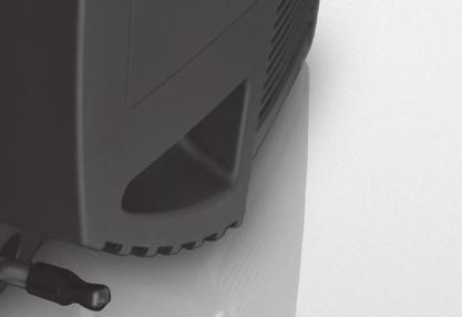
6 Always connect gas-tight adapter (18) of exhaust muffler (4) to unit. Replace damaged O-ring (13). Slide clamp (22) onto extraction duct (5). Slide adapter (18) of exhaust muffler (4) into muff (19) at unit as far as it will go. Click the exhaust gas tube attachment CBD (20) into the sockets (19). Check that the exhaust gas sound muffler (4) sits correctly. Slide extraction duct (5) onto muff (21) and secure with clamp (22). Fit air intake muffler to unit Route air intake muffler so that electrical connections remain accessible. Slide clamp (25) onto air intake muffler (7). Slide air intake muffler onto muff (26) as far as it will go and secure with clamp Fig Extraction air supply The cooling air (extraction air) that is needed to operate the burner is drawn from the vehicle interior via a fan in the wall cowl. The openings of this air extractor must be kept clear so that air can enter at all times. Fig. 15 Fig. 12 Always fit new O-ring to adapter of exhaust muffler after dismantling! Fit air intake muffler to cowl Fit long connecting end of air intake muffler (7) to cowl and attach short end to unit. Determine required installation length (shorten long connecting end if necessary depending on installation situation). Slide clamp (24) onto air intake muffler. Slide air intake muffler onto muff (23) as far as it will go and secure with clamp (24). Recirculated air intake The circulated air is drawn in by the unit. This must have one large or several small openings with a total area of at least 150 cm² between the living compartment (not the rear storage space) and the installation compartment. If a grid (not in scope of supply) is installed (Fig. 16), the same size requirement regarding cross-sectional area (150 cm²) for drawing in air must be observed. 23 Fig Fig. 16 The circulated air inlets must be arranged so that exhaust from the vehicle engine or the heater cannot be drawn in under normal operating conditions. It must be ensured by means of construction design that the heating air introduced into the vehicle is not polluted. 6
7 Warm air distribution Most of the warm air is fed into the floor area of the living compartment via flexible warm air ducts. Fuel connection The heater requires diesel fuel, as per the Australian Fuel Standard (Automotive Diesel). Operation with any form of biodiesel is not permitted. The fuel is extracted from the vehicle fuel tank (see fuel tank removal kit). Please only use the fuel hoses and lines that are included in the scope of delivery for installation. Permissible fuel line length Fig. 17 The 4 muffs on the unit are designed for the 65 mm diameter ÜR duct (part no ). Use only pressure-safe ducts in compliance with Truma quality requirements. Other ducts that do not meet our quality standard (particularly with regard to crown pressure resistance, duct diameter and number of grooves) must not be used. If the warm air duct has to be subjected to a considerable amount of bending immediately behind the warm air outlet of the unit in confined spaces, we recommend the use of the BGC 90 elbow (part no ). This elbow makes it possible to connect a ÜR warm air duct with a diameter of 65 mm or a VR warm air duct with a diameter of 72 mm. With a duct length of less than 2 m the air outlet must not be installed higher than the warm air duct muff. With a duct length of less than 50 cm, the duct must create a siphon between the muff and the outlet. The maximum fuel line length at the intake side is 2 m, and 6 m at the pressure side. Safety instructions for routing fuel lines Always cut fuel hoses and lines to length using a sharp knife. The areas that have been cut must not be compressed and must be free of burrs. Fuel lines must be securely attached in order to prevent damage and / or noise generation caused by vibration (recommended spacing between attachment points approx. 50 cm). Fuel lines must be protected from mechanical damage. Route fuel lines so that vehicle twisting, engine movements and the like do not adversely affect their stability. Protect fuel-carrying parts from heat that may affect operation (use suitable thermal protection hose made from fibre glass fabric with aluminium lining). L 50 cm L 50 cm Never route or secure fuel lines immediately adjacent to the exhaust ducts of the heater unit or the vehicle engine. If the lines cross, maintain an adequate distance away from hot components at all times provide heat radiation protection plates if necessary. Fig. 18 These measures prevent undesirable heating of the vehicle due to convection (cowl effect) during operation in summer. Do not leave gaps between fuel lines that are being connected using a fuel hose. This prevents problematic bubble formation. Correct line routing The ducts for warm air distribution must be inserted securely into the muff. A clip is attached to each muff to provide a more secure grip. In order to prevent heat accumulation when using the Combi, all 4 warm air connecting pieces must be attached. The cross-section of the hot air pipes must not be reduced by pipe connections or the like. If an EN end outlet that can be closed off is installed in one of the Combi warm air ducts (e.g. in the bathroom), a second outlet that cannot be closed off must be installed in the warm air duct. The warm air system is designed for each type of vehicle individually, on a modular basis. An extensive range of accessories are available. Diagrams showing optimum hot air system installation suggestions in all of the common caravan and motor home models can be requested free of charge from the Truma Service Centre. Incorrect line routing (bubble formation) Fig. 19 7
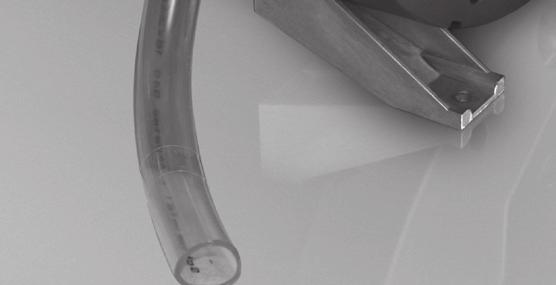
8 Installing the metering pump Always install metering pump with the pressure side (delivery direction) sloping upwards. Protect metering pump from heat (max. operating temperature 40 C), therefore do not install in the vicinity of sound mufflers and exhaust pipes. Metering pump installation position Fig Permissible metering pump intake and pressure levels 0 Connect unit and metering pump to fuel pipe Mark hole for leading through fuel pipe (in soundproofing hose) and metering pump connecting cable on floor of vehicle in a suitable location. Before drilling, always check for underlying / concealed cables, gas lines, frame sections and the like! Then seal the edges of the openings in the floor of the vehicle with underbody protection. Route fuel line and metering pump connecting cable so that they will not chafe. Please also use leadthrough bushings or edge protection profiles in locations where sharp edges such as metal panel leadthroughs are present. Route pressure-side fuel line in provided soundproofing hose made from cellular rubber. Allowing the fuel lines to come into contact with vehicle components or overtightening the cable binders may result in metering pump noise transmission (clicking). Connect fuel line (in soundproofing hose) to unit and metering pump as shown in diagram. Secure soundproofing hose and connecting cable to vehicle using hose holders (part no ) or attach loosely with cable binders (approx. every 50 cm). a c 36 b 30 Fig. 21 Pressure level from fuel tank to metering pump: a = max. 1,500 mm Intake level with depressurised fuel tank: b = max. 1,000 mm Intake level with fuel tank in which negative pressure occurs during removal (valve with 3 kpa in tank cap): b = max. 400 mm 37 Fig Pressure level from metering pump to heater: c = max. 2,000 mm Attaching the metering pump Attach metering pump (27) to vehicle in a suitable location using bracket (28) and holder (29) (included in scope of delivery) = Fuel line connection to unit 31 = Fuel hose 90 elbow 32 = Fuel line, inner diameter 2 mm (pressure line) 33 = Cellular rubber soundproofing hose 34 = Fuel hose 35 = Clamps 36 = Metering pump connecting cable 37 = Suction line from vehicle fuel supply Fuel tank removal kit 90 The metering pump is connected to the vehicle fuel supply using a vehicle-specific fuel tank removal kit. 27 Fuel tank removal kits on request. 29 Fig. 22 8
9 Water connection For operating the hot water system it is possible to use all pressure pumps and submergible pumps up to 280 kpa, also all mixing taps with or without electrical switch. In order to guarantee complete emptying of the water and to prevent pressures of greater than 450 kpa occurring in the hot water system, the enclosed pressure reducer (40), the enclosed water connectors ( ) and the enclosed drain valve (42) must be used! When using pressure pumps with high switching hysteresis, hot water may flow back through the cold water tap. To prevent backflow, we recommend that a non-return valve (nrv not included in the scope of supply) be fitted between the outlet to the cold water tap and the drain valve. Route all water lines so they drop down to drain valve! There shall be no guarantee claims for damage caused by frost! Mounting of the discharge pipe The discharge pipe (Fig ) is to be installed directly to the outside at a position protected against splash water (apply splash guard, if necessary). There must be no tap, valve or other restrictions in the discharge pipe. The discharge pipe must not be connected to other piping. The discharge pipe must fall continously and free of kinks from the P&T relief valve to the point of discharge The discharge pipe must not discharge into a safe tray. Drill a hole with 22 mm diameter and pass through the discharge pipe nrv Fig. 24 The supplied water connectors ( ) and drain valve (42) have a 12 mm rigid piping connection (e. g. John Guest System). For connecting to rigid pipes with other diameters appropriate adapters (not included in scope of delivery) must be used. Hoses with a diameter of 12 mm that are drinking water compatible, pressure-resistant (up to 450 kpa) and hot water-resistant up to +80 C must be used to connect the unit and the accessories. We recommend the use of John Guest pipes, insertion sleeves and hose clamps. As accessories Truma supplies the water connectors ( ) and drain valve (42) with a 10 mm / 3/8" diameter hose nipple. Route water pipes as short as possible and free of kinks. All pipe con nections must be secured (also cold water pipes)! Before the drain valve triggers, warming of the water and its resulting expansion may cause pressure of up to 450 kpa to occur (also possible with immersion pumps). When installing a water supply into the vehicle, please ensure that there is an adequate distance between the water hoses and the heat source (e.g. heater, warm air duct). Hose clips SC (part no ) are suitable for fastening the pipes to walls or the floor. These hose clips also make it possible to route water pipes on the heater s warm-air distribution pipes as a way to avoid the danger of frosting. Fig Ø 22 mm Installing drain valve Install drain valve (42) at a place which is easily accessible, near the hot water system. Drill a hole (18 mm diameter) in the floor of the vehicle. Attach drain hose (42a) to drainage socket, insert both through the floor and route outside. Fasten drain valve with 2 screws (included with delivery). Drain directly to the outside at a position protected against splash water (apply splash guard, if necessary) a A water hose may only be fitted at a clearance of 1.5 m to the heater on the warm air duct. The Truma hose clip SC (part no ) can be used if this distance is observed. In the case of parallel installations, e.g. openings through a wall, a spacer element should also be attached (e.g. insulation) to prevent contact. The included elbow fittings ( ) must always be used in order to completely empty the water and prevent the water pipes on the unit from leaking over the long-term! Elbow fitting (46 with aeration valve) is connected to the upper warm water connection; the second elbow fitting (45) is connected to the lower cold water connection. Fig. 26 Ø 18 mm 9
10 Installation of the pressure reducer Depending on the scope of supply pressure reducer A or B has to be installed. Pressure reducer A The pressure reducer (40) must be fitted between the drain valve and water pump in accordance with the direction of flow (indicated by arrow). Fasten the pressure reducer to the floor. Fig x Push the venting hose, external diameter 11 mm (47), onto the hose grommet of the venting valve (46a), and lay it to the outside without any kinks. Ensure that the bend radius is not smaller than 40 mm. Cut off the aeration hose about 20 mm below the vehicle floor at a 45 angle to the direction of travel (see figure). Check all connections for water leaks: Repair leaks as needed. Repeat check for water leaks and take any necessary steps to repair the leaks at all water connections. Installing the room temperature sensor When selecting the location, bear in mind that the room temperature sensor must not be subjected to any direct radiant heat. For optimum room temperature regulation, we recommend that the room temperature sensor be fitted above the entrance door. Pressure reducer B The pressure reducer (40) must be fitted between the drain valve and water pump in accordance with the direction of flow (indicated by arrow). 3 Nm 40 3 Nm Fig mm Fig. 28 Routing of water pipes Connect cold water supply (41) to drain valve (42). Route the water pipes without tension in order to ensure that the drain valve will work properly! 46a 46 Please ensure that the sensor is always attached to a vertical wall. There must be a free flow of interior air around the sensor. Drill a hole 10 mm in diameter. Guide the connection cable through the drillhole from behind and plug the cable end into the sensor by means of an insulated connector plug (there is no need to be concerned about polarity). Slide in the room temperature sensor and lay the cable end with the two insulated connector plugs to the heating electronics unit (extend to a maximum overall length of 10 m using 2 x 0.5 mm² cable if necessary). The provided room temperature sensor must always be connected, otherwise the heater will switch to fault. Installing the control panel The installation of the control panel is described in the instructions included with the control panel mm 45º Fig. 29 Slide elbow fitting (45) onto cold water connecting pipe and elbow fitting with integrated ventilating valve (46) onto hot water connecting pipe of heater as far as it will go. Pull in opposite direction in order to make sure the elbow fittings are securely attached. Create the pipe connection (43) for cold water supply between drain valve (42) and the inlet on the hot water system. Route the hot water supply (44) from the elbow connec tion with integrated vent valve (46) to the hot water consumers. 10
11 Electrical connections Route connecting cables in such a way that they cannot chafe. Please also use leadthrough bushings or edge protection profiles where there are sharp edges such as metal panel leadthroughs. The connecting cables must not be attached to or come into contact with metal surfaces, the exhaust duct or warm air ducts. The electrical connections are located under the connection cover (60). The cover can be removed by pressing and simultaneously sliding it in the direction of the arrow. When removing or installing the connection cover on the connection cables, make sure that the cables are not pulled out or become pinched. The connecting cables and plugs must not be subjected to force. Bundle connecting cables (see figure) and secure each one to housing using a cable binder in order to provide strain relief. Fig. 33 All cables must be securely attached and must not become loose or disconnected due to vibration risk of fire! open BEDIENTEIL DIAGNOSE Connection 12 V Electric cables, switching units and control units for heaters must be arranged in the vehicle in such a way that their satisfactory operation cannot be adversely affected under normal operating conditions. All cables leading to the outside must be splash proof at the leadthrough opening. Prior to working on electric components the appliance must be disconnected from the power supply. Swit ching off at the control panel is not sufficient! 20AT FC 10AT Fensterschalter ZUCB Raumfühler JE ASG When carrying out electric welding work on the body, the appliance connection must be disconnected from the vehicle electrical system. 70 Fig = input voltage +12 V (spade connector 6.3 mm) 62 = input voltage ground (spade connector 6.3 mm) 63 = not used 64 = device fuse: 10 A slow (T 10 A) 65 = wire bridge (or window switch accessory) 66 = not used 67 = room temperature sensor 68 = control panel / diagnostic connector* 69 = control panel / diagnostic connector* 70 = metering pump 71 = burner fuse 20 A (slow-acting) 6.3 x 32 mm 72 = extractor fan 73 = burner diagnostic connector * Alternative connections. The unit is equipped with reverse polarity protection. If the unit is connected with incorrect polarity, there will be no display on the LED. The unit can be used after establishing proper polarity and replacing the fuse (64). The heater requires a constant 12 V supply. The connection should be made via a minimum of 6 mm cross section low voltage cable direct to the 12 V battery terminals, both positive and negative. The positive and negative leads must be fused with a 12 V 20 A fuse. If fitting an isolation switch, the switch must be installed in such a position that the heater cannot be switched off unintentionally. The heater must always be turned off at the heater control. The 12 V isolation switch should only be used after the heater has completed its cool down cycle and has stopped completely. Do not connect any other consumers to the supply line! When power packs or power supply units are being used, note that the output voltage is between 11 V and 15 V and the alternating current ripple is < 1.2 Vpp. Connecting room temperature sensor to the unit Fig. 32 Plug the connection cable s plug onto connection (67) (no need to observe polarity). All connections to the unit should be made with sagging connection cables. This will prevent condensation water from running down the connection cables and into the unit. 11
12 Control panel / air conditioning system The following connecting combinations are possible. 1 CP plus control panel and 1 Air conditioning system Combi Suitable systems see CP plus control panel operating instructions Insert the plug of the connecting cable into one of the connections (68 or 69). Make sure that the plug engages. Metering pump connection Function check Check all functions of the appliance, as specified in the operating instructions, in particular the water draining function. There shall be no guarantee claims for damage caused by frost! The operating instructions must be handed to the owner of the vehicle. Warnings The installer or vehicle owner must apply the yel low sticker with the war ning information, which is enclosed with the appliance, to a place in the vehicle where it is clearly visible to all users (e.g. on the wardrobe door)! Ask Leisure-Tec to send you stickers, if neces sary. If an automatic filling unit is used to fill the fuel lines, make electrical connection to metering pump after filling. Attach connector (74) of connecting cable to metering pump and connector (75) to connection (70) of unit. Please ensure that connectors engage properly. Fig Wind up excess cable and secure in a suitable location using cable binders. Extraction fan connection Attach connector (11) of extraction fan cable to unit connection (72). Ensure that the plug engages. Wind up excess cable (9) and secure in a suitable location using cable binders Fig. 35 View vehicle interior Initial start-up During the initial operation of a brand new appliance a slight amount of fumes and smell may be noticed for a short while. Filling the fuel lines The heater normally has to be started up several times to fill the fuel lines. Connect unit to control panel to do this. The unit automatically performs 2 start attempts (initial start and repeat) per switchon procedure with a run time of 2 minutes in each case. If no flame is detected after the repeat start, the unit switches to fault and has to be switched off and on again at the control panel. After a total of 15 unsuccessful starting attempts (initial and repeat start) without forming a flame, the equipment is blocked. To remove the block, please contact the Leisure-Tec Service Centre (see Check fuel lines and connections for leaks after filling the fuel lines. 12
13 13
14 14
15 15
16 In Australia, always notify the Leisure-Tec Service Centre if problems are encountered; in other countries the relevant service partners should be contacted ( Having the equipment model and the serial number ready (see type plate) will speed up processing /2018 Leisure-Tec Pty. Ltd. 50 Metrolink Circuit Campbellfield, VIC 3061 Australia Service (Australia) Telephone:
Truma VarioHeat eco AU. Installation instructions Page 2
 Truma VarioHeat eco AU Installation instructions Page 1 3 4 Installation example Fig. 1 9 7 8 6 5 1 Room temperature sensor Control panel Truma CP plus VarioHeat 3 Electric window switch (optional) 4 Exhaust
Truma VarioHeat eco AU. Installation instructions Page 2
 Truma VarioHeat eco AU Installation instructions Page 1 3 4 Installation example Fig. 1 9 7 8 6 5 1 Room temperature sensor Control panel Truma CP plus VarioHeat 3 Electric window switch (optional) 4 Exhaust
Truma UltraRapid Hot Water System
 Truma UltraRapid Hot Water System LPG and 230 V / 240 V Electric Storage Water Heater Operating instructions Page 4 Installation instructions Page 8 To be kept in the vehicle! BGA 14 / BGEA 14 LPG (Propane)
Truma UltraRapid Hot Water System
 Truma UltraRapid Hot Water System LPG and 230 V / 240 V Electric Storage Water Heater Operating instructions Page 4 Installation instructions Page 8 To be kept in the vehicle! BGA 14 / BGEA 14 LPG (Propane)
Combi 2 E / 4 E CP plus (Australia) Operating instructions Page 2. To be kept in the vehicle!
 Operating instructions Page 2. To be kept in the vehicle!") Combi 2 E / 4 E CP plus (Australia) Operating instructions Page 2 To be kept in the vehicle! Combi 2 E / 4 E CP plus (Australia) 4 5 1 2 6 10 13 15 16 12 8 10 14 6 1 Control panel (digital) 2 Room temperature
Combi 2 E / 4 E CP plus (Australia) Operating instructions Page 2 To be kept in the vehicle! Combi 2 E / 4 E CP plus (Australia) 4 5 1 2 6 10 13 15 16 12 8 10 14 6 1 Control panel (digital) 2 Room temperature
Trumatic E. Trumatic E 2400 (Australia) Operating instructions Page 4 Installation instructions Page 7. To be kept in the vehicle!
 Operating instructions Page 4 Installation instructions Page 7. To be kept in the vehicle!") Trumatic E 7 7 2 9 9 4 Trumatic E 2400 (Australia) Operating instructions Page 4 Installation instructions Page 7 To be kept in the vehicle! Trumatic E 2400 (Australia) Table of contents Installation example...
Trumatic E 7 7 2 9 9 4 Trumatic E 2400 (Australia) Operating instructions Page 4 Installation instructions Page 7 To be kept in the vehicle! Trumatic E 2400 (Australia) Table of contents Installation example...
Boiler. L. P. Gas and 230/240 V Electric Storage Water Heater Model B 10 / B 14 from 11/2003
 Boiler L. P. Gas and 230/240 V Electric Storage Water Heater Model B 10 / B 14 from 11/2003 Boiler 60 70 230 V ~ Boiler EL Operating instructions Page 3 Installation instructions Page 6 To be kept in the
BlueHeat AirTop 2000 Heater
 BlueHeat AirTop 000 Heater Air Heater Installation Manual Ford E-Series 6.0L Diesel Beginning Model Year: 006 Special instructions for these models Part locations may differ slightly dependent on the vehicle
Combi D 6 (Australia)
") Combi D 6 (Australia) Operating instructions Page 2 To be kept in the vehicle! Combi 9 7 4 3 5 5 2 3 1 1 60 60 Comfort on the move Combi D 6 (Australia) 1 2 3 5 6 13 12 14 7 11 9 10 1 Control panel 2 Time
Combi D 6 (Australia) Operating instructions Page 2 To be kept in the vehicle! Combi 9 7 4 3 5 5 2 3 1 1 60 60 Comfort on the move Combi D 6 (Australia) 1 2 3 5 6 13 12 14 7 11 9 10 1 Control panel 2 Time
Boiler L. P. Gas and 230 / 240 V Electric Storage Water Heater Model B 10 / B 14 from 08/2008
 Boiler L. P. Gas and 230 / 240 V Electric Storage Water Heater Model B 10 / B 14 from 08/2008 Operating instructions Page 2 Installation instructions Page 6 To be kept in the vehicle! Comfort on the move
1. Take the hoses and elbow out of the holders, depending on model. max. 100 cm. min. * cm
 Safety instructions The washing machine is heavy - take care when lifting. Caution: frozen hoses may rip/burst. Do not install the washing machine in areas exposed to frost or outdoors. The washing machine
Saphir comfort RC (Australia) Operating instructions Page 2 Installation instructions Page 9. To be kept in the vehicle!
 Operating instructions Page 2 Installation instructions Page 9. To be kept in the vehicle!") Saphir comfort RC (Australia) Operating instructions Page 2 Installation instructions Page 9 To be kept in the vehicle! Saphir comfort RC air conditioning system 3b 3b 5 4 3b Fig. 2 Fig. 1 3a 1 2b 2a Installation
Saphir comfort RC (Australia) Operating instructions Page 2 Installation instructions Page 9 To be kept in the vehicle! Saphir comfort RC air conditioning system 3b 3b 5 4 3b Fig. 2 Fig. 1 3a 1 2b 2a Installation
UB1 AIR CONDITIONING UNIT INSTALLATION INSTRUCTIONS
 UB1 AIR CONDITIONING UNIT INSTALLATION INSTRUCTIONS INSTALLATION INSTRUCTIONS: Carefully read these instructions before installing your new air-conditioner. AUSTRALIAN AUTOMOTIVE AIR AL00500054E 1 Table
Moisture inside the drum is due to final testing.
 Safety instructions Scope of delivery depending on model Moisture inside the drum is due to final testing. Removing the transport braces Water connection depending on model The washing machine is heavy
Installation Manual. For Australian refrigerator models: N304M.3 (93 liter 3-way operation with LP gas, 240 volts AC, or 12 volts DC )
") Installation Manual For Australian refrigerator models: N304M.3 (93 liter 3-way operation with LP gas, 240 volts AC, or 12 volts DC ) N404M.3 (128 liter 3-way operation with LP gas, 240 volts AC, or 12
Installation Manual For Australian refrigerator models: N304M.3 (93 liter 3-way operation with LP gas, 240 volts AC, or 12 volts DC ) N404M.3 (128 liter 3-way operation with LP gas, 240 volts AC, or 12
Installation Instructions. For the 18 Built-In Dishwasher and Front Color Panels
 Installation Instructions For the 18 Built-In Dishwasher and Front Color Panels Printed in USA 154232102 Before You Begin DO NOT INSTALL DISHWASHER UNTIL YOU HAVE READ ALL INSTRUCTIONS. FOR YOUR SAFETY,
Specifications. Vacuum motor power consumption(w/hp) 1200 / 1.6. Exhaust water pump power consumption(w/hp 800 / 1.1
 1200 / 1.6. Exhaust water pump power consumption(w/hp 800 / 1.1") Specifications Rated voltage (V) AC 110-120V or 220-240V / 50-60Hz Vacuum motor power consumption(w/hp) 1200 / 1.6 Exhaust water pump power consumption(w/hp 800 / 1.1 Exhaust water pump flow (GPH/LPH)
Specifications Rated voltage (V) AC 110-120V or 220-240V / 50-60Hz Vacuum motor power consumption(w/hp) 1200 / 1.6 Exhaust water pump power consumption(w/hp 800 / 1.1 Exhaust water pump flow (GPH/LPH)
HYDRONIC II Technical description, installation, operating and maintenance instructions.
 HYDRONIC II Technical description, installation, operating and maintenance instructions. Heater for petrol Order No. Hydronic II B 4 S 12 V 20 1909 05 00 00 B 5 S 12 V 20 1904 05 00 00 Heater for diesel
INSTALLATION INSTRUCTIONS UNDERCOUNTER DISHWASHERS
 INSTALLATION INSTRUCTIONS UNDERCOUNTER DISHWASHERS VIKING 111 Front Street Greenwood, Mississippi 38930 USA (662) 455-1200 IMPORTANT - PLEASE READ AND FOLLOW Before beginning - please read these instructions
BR342 Ducted Installation Instructions Australian Version Electronic Wall Control
 Australian Version Electronic Wall Control 1 Introduction The BR342 reverse cycle rooftop air-conditioner is designed for installation onto Recreational Vehicles (RV s) at the time of manufacture or as
User Guide Compact-7 series
 User Guide Compact-7 series Boiler-CH Calorifier Combi Introductory remarks Congratulations on the purchase of your Kabola Compact 7. Kabola has been a manufacturer of oil-fired heating systems since 1947.
Moisture inside the drum is due to final testing.
 Safety instructions Scope of delivery depending on model Moisture inside the drum is due to final testing. Removing the transport safety devices Water connection depending on model The washing machine
INSTALLATION INSTRUCTIONS
 INSTALLATION INSTRUCTIONS Gas Cooktop CG905DW models NZ AU www.fisherpaykel.com 590684B 11.14 1 Safety and warnings! WARNING! Electrical Shock Hazard Before carrying out any work on the electrical section
VIESMANN. Installation instructions VITOCELL 300-B. for contractors. Vitocell 300-B Type EVBA-A. Dual mode DHW cylinder, 300 and 500 l
 Installation instructions for contractors VIESMANN Vitocell 300-B Type EVBA-A Dual mode DHW cylinder, 300 and 500 l VITOCELL 300-B 1/2017 Dispose after installation. Safety instructions Please follow these
JOHN DEERE GATOR HPX/XUV 2 PASSENGER HEATER INSTALLATION INSTRUCTIONS (p/n: 9PH20S30)
") P. 1 of 12 JOHN DEERE GATOR HPX/XUV 2 PASSENGER HEATER INSTALLATION INSTRUCTIONS (p/n: 9PH20S30) Item: Qty: Description: 1 2 1 x 1 x 5/8 Tee Fitting 2 2 Plastic Snap-in Hose Grommet 3 4 1-1/2" Hose Clamps
P. 1 of 12 JOHN DEERE GATOR HPX/XUV 2 PASSENGER HEATER INSTALLATION INSTRUCTIONS (p/n: 9PH20S30) Item: Qty: Description: 1 2 1 x 1 x 5/8 Tee Fitting 2 2 Plastic Snap-in Hose Grommet 3 4 1-1/2" Hose Clamps
Thermo 50 Coolant Heater. HMMWV 6.2 and 6.5 Liter Diesel. Table of Contents. Foreword
 Thermo 50 Coolant Heater HMMWV 6. and 6.5 Liter Diesel Special instructions for these models Part locations may differ slightly dependent on the vehicle model. Table of Contents Foreword Parts List 3 Vehicle
BlueHeat Coolant Heater
 BlueHeat Coolant Heater Dodge Ram 500 / 3500 003 / 004-5. Liter Gasoline 003 / 006-5.9 Liter Diesel 00 6. Liter Diesel Installation Instructions DOC P/N 500068B KIT P/N 5000498C PRELIMINARY INFORMATION
Installation instructions Refrigerators and freezers for integrated use, door-on-door
 Installation instructions Refrigerators and freezers for integrated use, door-on-door 010612 7084276-04 IK/ IKB/ IKP/ IG/ IGN... 1/ 3/ 6 General safety information Contents 1 General safety information...
Installation Instructions
 Installation Instructions For the 18" Built-In Dishwasher Sears, Roebuck and Co. Sears Canada, Inc. Hoffman Estates, IL 60179 U.S.A. Toronto, Ontario, Canada M5B 2B8 154435201 Before You Begin DO NOT INSTALL
SECTION AUXILIARY HEATER
 14-301.03/ 1 2010MR12 SECTION 14-301.03 GENERAL DESCRIPTION The Thermo 300 auxiliary heating system is used in conjunction with the vehicle s heating system, in order to heat the passenger compartment
DC Heat Recovery Unit MVHR Wholehouse heat recovery unit
 DC Heat Recovery Unit MVHR Wholehouse heat recovery unit Stock Ref. N DC Heat Recovery Unit MVHR 443423 Installation, Maintenance & Users Instructions PLEASE READ INSTRUCTIONS IN CONJUNCTION WITH ILLUSTRATIONS.
HD 5/11 C Plus. Automatic pressure cut-off. Pump technology
 HD 5/11 C Plus Compact cold-water high pressure cleaner. With its compact dimensions, robust construction and greatest possible manoeuvrability, this unit is a credit to the compact class. 1 Automatic
Installation manual. 2kW Calaer air heater 4kW Calaer air heater
 Installation manual 2kW Calaer air heater 4kW Calaer air heater 1. Introduction and scope 1. Introduction and scope The Calaer series products provide continuous heating, ensuring a pleasant cabin temperature.
EUTECTIC EC-10DV Series
 EUTECTIC EC-10DV Series DIRECT VENT OIL-FIRED WATER BOILER/NO. 2 OIL VENTING INSTALLATION INSTRUCTIONS CONTENTS..........................................PAGE Basic Guidelines..........................................1
Installation Instructions
 Installation Instructions KFN 9855 ide en - CA Installation, repair and maintenance work should be performed by a Miele authorized service technician in accordance with national and local safety regulations
INSTALLATION AND USER S MANUAL COOKER HOOD RS-600/A-S
 INSTALLATION AND USER S MANUAL COOKER HOOD RS-600/A-S RS-600 (CHS60SS)-GB-05.indd 1 6/8/2010 9:30:59 AM TABLE OF CONTENTS 1. Introduction 2 2. Safety precaution 2 3. Intended use 3 4. Parts supplied 3
INSTALLATION GUIDE NZ AU D
 GAS COOKTOP CG905DW models INSTALLATION GUIDE NZ AU 590684D 08.17 1 SAFETY AND WARNINGS! WARNING! Electrical Shock Hazard Before carrying out any work on the electrical section of the appliance, it must
CANOPY RANGEHOOD ONBOARD INSTALLATION INSTRUCTIONS
 Congratulations on your purchase! Thank you for choosing a Sirius product. CANOPY RANGEHOOD ONBOARD INSTALLATION INSTRUCTIONS SLTC 97 900 EAN# 9351116001612 SL22 900 EAN# 9351116000660 SL7 1200 EAN# 9351116000813
Electronically controlled instantaneous water heater. MCX: 27300, and models. Installation instructions
 Electronically controlled instantaneous water heater MCX: 27300, 27400 and 27600 models Installation instructions These appliances deliver water not exceeding 50 ºC in accordance with AS3498. 1. Overview
HOT WASHER MODEL NO: KING150
 WARNING: Do not use the hot washer without reading this manual HOT WASHER MODEL NO: KING150 PART NO: 7320175 OPERATION & MAINTENANCE INSTRUCTIONS LS1215 INTRODUCTION Thank you for purchasing this CLARKE
INSTALLATION INSTRUCTIONS FOR 6532 SERIES PACKAGE HEAT PUMP
 INSTALLATION INSTRUCTIONS FOR 6532 SERIES PACKAGE HEAT PUMP RV Products A Division of Airxcel, Inc. P.O. Box 4020 Wichita, KS 67204 1976-360 (1-02) PP TABLE OF CONTENTS 1. Warnings......................................................
ZEST HOOD. Instructions Manual.
 ZEST HOOD Instructions Manual www.rangemaster.co.uk INDEX EN RECOMMENDATIONS AND SUGGESTIONS... 3 CHARACTERISTICS... 4 INSTALLATION... 6 USE... 14 MAINTENANCE... 16 2 RECOMMENDATIONS AND SUGGESTIONS The
INSTALLATION INSTRUCTIONS TD75. Vented tumble dryer DOMESTIC. Carefully read the instructions for use before using the dryer.
 INSTALLATION INSTRUCTIONS TD75 Vented tumble dryer DOMESTIC Carefully read the instructions for use before using the dryer. Dear Customer, Read these instructions carefully and completely before you install
CARVER CASCADE 2 & CASCADE 2 GE CARAVAN WATER HEATER INSTALLATION INSTRUCTIONS LEAVE THESE INSTRUCTIONS WITH THE USER
 CARVER - CASCADE 2 & CASCADE 2 GE CARAVAN WATER HEATER INSTALLATION INSTRUCTIONS LEAVE THESE INSTRUCTIONS WITH THE USER 1:0 SPECIFICATIONS Water capacity Water connections Water supply 9 litres (2 gallons)
Zip HydroTap Miniboil
 Installation and Operating Instructions Zip HydroTap Miniboil Boiling and Ambient drinking water for kitchens and the home. Miniboil BA tap HydroTap Classic BA tap Affix Model Number Label Here 89585 GP
Thermo Pro 50 Eco 24 Volt Diesel
 Coolant Heater Thermo Pro 50 Eco 24 Volt Diesel Installation Manual Improper installation or repair of Webasto heating and cooling systems can cause fire or the leakage of deadly carbon monoxide leading
Calaer Marine add-on kit manual. 2kW Calaer air heater 4kW Calaer air heater
 Calaer Marine add-on kit manual 2kW Calaer air heater 4kW Calaer air heater 1. Introduction and scope 1. Introduction and scope The Calaer marine add-on kit is designed to be used with the Calaer air
INSTALLATION GUIDE NZ AU E
 GAS COOKTOP CG604DX & CG905DX models INSTALLATION GUIDE NZ AU 590447E 08.17 1 SAFETY AND WARNINGS Electrical shock hazard WARNING! Before carrying out any work on the electrical section of the appliance,
SAFIRE 1600D, 1800D and 2100D Diesel / fuel oil heaters USAGE, INSTALLATION AND MAINTENANCE
 SAFIRE 1600D, 1800D and 2100D Diesel / fuel oil heaters 1 Heater kit contains : Heater, mounting bracket Fuel hose (3 meters), pump, a fuel tank connection to standard tanks (15, 22, 30 litres) Power supply
HG 675 CX 60 HG 675 CN 60 HG 675 CW 60
 HG 675 X 60 HG 675 CX 60 HG 675 CN 60 HG 675 CW 60 1 2 1. : 93/68: 90/396: 2006/95/CE: 2004/108/CE: - 1935/2004:. 2002/95/CE: RoHS 2.,.,,,,...,. (,..)..,,.,. ( ),,, ;,,.,.....,.,,,,,,...,. (..),,.,..,.,,,,
OP44-1 REV 2: Removed depiction of air intake hole in the CB-907A Right Aft Case Baffle.
 REVISION DESCRIPTION: OP44-1 REV 2: Removed depiction of air intake hole in the CB-907A Right Aft Case Baffle. OP44-4 REV 1: Steps rewritten to describe the air intake hole on the CB-907A Right Aft Case
LEIHDC70SC - LEIHDC70BB LEIHDC70BC. Instructions Manual.
 LEIHDC70SC - LEIHDC70BB LEIHDC70BC Instructions Manual www.rangemaster.co.uk INDEX EN RECOMMENDATIONS AND SUGGESTIONS...3 CHARACTERISTICS...4 INSTALLATION...5 USE...8 MAINTENANCE...9 2 RECOMMENDATIONS
CANOPY RANGEHOOD OFFBOARD INSTALLATION INSTRUCTIONS
 Congratulations on your purchase! Thank you for choosing a Sirius product. CANOPY RANGEHOOD OFFBOARD INSTALLATION INSTRUCTIONS SLTC EM 107 G900 EAN# 9351116001766 SLEM 107 S900 EAN# 9351116001759 SLEM
Zip Tudor. Affix Model Number Label Here Installation Section & Operating Heading Instructions. Single point open outlet (vented) water heaters
 water heaters") Zip Tudor Installation Section & Operating Heading Instructions Single point open outlet (vented) water heaters Affix Model Number Label Here 81333 Above-Sink Tudor (No tapware included) Accessory Tapware
Zip Tudor Installation Section & Operating Heading Instructions Single point open outlet (vented) water heaters Affix Model Number Label Here 81333 Above-Sink Tudor (No tapware included) Accessory Tapware
Installation Instructions T 9822 Gas Dryer. en - US, CA. To prevent accidents
 Installation Instructions T 9822 Gas Dryer To prevent accidents en - US, CA and appliance damage read these instructions before installation or use. M.-Nr. 07 431 110 2 WARNING For your safety the information
THERMOFILM CONVECTIVE PANEL HEATER INSTALLATION, OPERATION AND MAINTENANCE MANUAL. Models: CP 2400 CP 2000 CP 1500 CP 1000 TABLE OF CONTENTS
 THERMOFILM CONVECTIVE PANEL HEATER Rev C JUL13 INSTALLATION, OPERATION AND MAINTENANCE MANUAL Models: CP 2400 CP 2000 CP 1500 CP 1000 TABLE OF CONTENTS 1. Important Safety Instructions 2. Specification
Operating instructions
 SOLARTHERMIE - SOLAR THERMAL - SOLAR TÉRMICO - SOLAIRE THERMIQUE Operating instructions Temperature Differential Controller inputs, 1 output These operating instructions are part of the product. US Read
Dishwasher. Installation manual DW60M9990AP
 Dishwasher manual DW60M9990AP DW9000M_DD68-00197B-00_EN.indd 1 6/1/2017 4:34:14 PM Contents Contents 3 What s included 3 requirements 7 Dimensions and specifications 9 Step-by-step installation 11 2 English
LS Condensate Removal Pump INSTRUCTION MANUAL REVISION A
 LS Condensate Removal Pump INSTRUCTION MANUAL 6-71-075-115 REVISION A CAUTION: Combustible liquids may not be pumped! The condensate pump may not be run dry, as this can destroy the bearings in a very
Installation Manual EF5000 NZ
 Installation Manual EF5000 NZ Important: The appliance shall be installed in accordance with; Local gas fitting regulations Municipal building codes AS/NZS 5601.1.1:2010 Gas Installation Any other relevant
Installation guide Sahara & Sahara Plus
 Installation guide Sahara & Sahara Plus Installation requirements. Components for Billi Sahara 310, 320, 360 & 3120 Models Before commencing installation, ensure you have identified the following. 1. Underbench
Cold water compact class HD 5/11 C. Standard accessories: Trigger gun Extended highpressure. Technical data
 Cold water compact class HD 5/11 C Compact cold-water high pressure cleaner. With its compact dimensions, robust construction and greatest possible manoeuvrability, this unit is a credit to the compact
ELECTRIC DRYER INSTALLATION INSTRUCTIONS
 ELECTRIC DRYER INSTALLATION INSTRUCTIONS Table of Contents DRYER SAFETY... 2 INSTALLATION REQUIREMENTS... 3 Tools and Parts... 3 LOCATION REQUIREMENTS... 4 ELECTRICAL REQUIREMENTS... 6 INSTALL LEVELING
Installation Electric Dryers Instructions 01
 Installation Electric Dryers Instructions 01 Questions? Call 800.GE.CARES (800.432.2737) or visit our Web site at: GEAppliances.com This is the safety alert symbol. This symbol alerts you to potential
SEA FROST BD 12 OR 24-VOLT D.C. AIR-COOLED SYSTEM
 148 OLD CONCORD TURNPIKE BARRINGTON, NH 03825 USA TEL (603) 868-5720 FAX (603) 868-1040 1-800-435-6708 E-Mail:sales@seafrost.com www.seafrost.com SEA FROST BD 12 OR 24-VOLT D.C. AIR-COOLED SYSTEM CONDENSING
COMMERCIAL GAS AND ELECTRIC STACKED WASHER/ DRYER INSTALLATION INSTRUCTIONS
 COMMERCIAL GAS AND ELECTRIC STACKED WASHER/ DRYER INSTALLATION INSTRUCTIONS MODELS MLG19PD, MLE19PD The installation, including a proper exhaust system, is the responsibility of the owner. LEAVE THESE
Atmos EasySolar. Installation Instructions for. Sloping roof and flat roof installation with evacuated tube collector
 Atmos EasySolar Installation Instructions for Atmos EasySolar Sloping roof and flat roof installation with evacuated tube collector Atmos Heating Systems TBS Building Supplies Ltd Hackwood Road Daventry
ELECTRIC DRYER INSTALLATION INSTRUCTIONS
 ELECTRIC DRYER INSTALLATION INSTRUCTIONS Table of Contents DRYER SAFETY... 2 INSTALLATION REQUIREMENTS... 3 Tools and Parts... 3 LOCATION REQUIREMENTS... 4 ELECTRICAL REQUIREMENTS... 5 INSTALL LEVELING
Questions? Call 800.GE.CARES ( ) or visit our Web site at: GEAppliances.com In Canada, call or visit
 or visit our Web site at: GEAppliances.com In Canada, call or visit") Installation Instructions Electric Dryer 01 Questions? Call 800.GE.CARES (800.432.2737) or visit our Web site at: GEAppliances.com In Canada, call 1.800.561.3344 or visit www.geappliances.ca BEFORE YOU
Installation Instructions Electric Dryer 01 Questions? Call 800.GE.CARES (800.432.2737) or visit our Web site at: GEAppliances.com In Canada, call 1.800.561.3344 or visit www.geappliances.ca BEFORE YOU
RV Products Division INSTALLATION INSTRUCTIONS FOR SERIES HEAT PUMP INSTRUCTIONS D INSTALLATION DE LA POMPE À CHALEUR SÉRIE 47000
 RV Products Division INSTALLATION INSTRUCTIONS FOR 47000 SERIES HEAT PUMP INSTRUCTIONS D INSTALLATION DE LA POMPE À CHALEUR SÉRIE 47000 TABLE OF CONTENTS I. General Information..............................................
FRANKE DESIGNER GAS COOKTOP 90CM
 page 1 of 7 510 880 45 480 Min 50 860 Min 600 SPECIFICATIONS Recommended use Material Colour availability Weight Dimensions Voltage Domestic Stainless Steel Stainless Steel 18.2kg 880 x 510 x 45mm 220-240V
U tube models PTU 09, 12, 15, 25, 30, 35, 40, 45. single linear tube models PTS 09, 12, 15, 25, 30, 35, 40, 45
 U tube models PTU 09, 2, 5, 25, 30, 35, 40, 45 & single linear tube models PTS 09, 2, 5, 25, 30, 35, 40, 45 installation, servicing & operating instructions INSTALLATION, SERVICING AND OPERATING INSTRUCTIONS
PRELIMINARY INSTALLATION. Operation & Service Manual. Carrier Transicold Europe 03/09/07 Viento - Installation/Rev- #1/56
 INSTALLATION Carrier Transicold Europe 03/09/07 Viento - Installation/Rev- #1/56 INSTALLATION Table of content Introduction...4 Preparation before installation...5 Vehicle partition... 6 Box preparation...7
SERVICE MANUAL WASHING. Washer-dryers HEC-RIM HEC-ARCHED. Structural characteristics, electrical components, accessibility
 SERVICE MANUAL WASHING HEC-RIM HEC-ARCHED Washer-dryers ELECTROLUX HOME PRODUCTS ITALY S.p.A. Spares Operations Italy Corso Lino Zanussi,30 Publication number I - 33080 PORCIA /PN (ITALY) 599 70 40-15
WC2 & WC3 Installation & Maintenance Instructions
 WC2 & WC3 Installation & Maintenance Instructions Please leave this instruction booklet with the home owner as it contains important guarantee, maintenance and safety information WC3 shown WC2 WC3 IMPORTANT
SNUGGER SNUGGER AIR HEATER AIR SNUGGER USA Technical description. Installation instructions. Operating instructions
 SNUGGER Technical description Installation instructions Operating instructions Maintenance instructions SNUGGER AIR HEATER AIR SNUGGER USA 1 877 500-2212 Page 1 Description Contents 1. Operating Principle
Pizza Oven with Stand
 Pizza Oven with Stand Cooks up to 3 pizzas at a time Use to cook a variety of food Easy clean vitreous enamel interior Model No. P0104 Powerful 22MJ/h stainless steel burner Viewing window and temperature
Installation guide COMBI E. Before installing read this guide first
 Installation guide COMBI E Before installing read this guide first Introduction The operation of the Quooker COMBI E The Quooker COMBI E supplies boiling water and hot water. The tank is vacuuminsulated
Instructions Manual CTB CTB 9407
 Instructions Manual CTB 6407 - CTB 9407 INDEX EN RECOMMENDATIONS AND SUGGESTIONS... 3 CHARACTERISTICS... 4 INSTALLATION... 5 USE... 7 MAINTENANCE... 8 2 RECOMMENDATIONS AND SUGGESTIONS The Instructions
Installation Manual EF5000 AUS & NZ
 Installation Manual EF5000 AUS & NZ This manual is ONLY for fires with a serial No. from 80600 to 80999. Important: The appliance shall be installed in accordance with; Local gas fitting regulations Municipal
Technical data. Bathroom/shower room installations. Water services (WRAS approved)
") Technical data The Closomat toilet MUST be installed by a competent or qualified person. Explanation of symbols Safety instructions in this manual are identified by symbols. The safety instructions are
Technical data The Closomat toilet MUST be installed by a competent or qualified person. Explanation of symbols Safety instructions in this manual are identified by symbols. The safety instructions are
ELECTRIC DRYER INSTALLATION INSTRUCTIONS
 ELECTRIC DRYER INSTALLATION INSTRUCTIONS Para una version de estas instrucciones en español, visite www.whirlpool.com Table of Contents DRYER SAFETY... 2 Installation Requirements... 3 Tools and Parts...
AirUnit. Installation instructions. mfh systems modern floor heating. Decentralised domestic ventilation
 mfh systems modern floor heating AirUnit Decentralised domestic ventilation Installation instructions List of contents, Installation instructions Page 1. General information... 03 2. Function / planning
Installation Instructions. Filtered Chilled drinking water for commercial kitchens and tea rooms.
 Installation Instructions Zip HydroTap Filtered Chilled drinking water for commercial kitchens and tea rooms. Affix Model Number Label Here 801525 801525 - Zip HydroTap Installation Instructions - Nov.
Enzo Concealed Shower Mixing Valve
 Enzo Concealed Shower Mixing Valve EZ40010CP, EZ40013CP & EZ40014CP Installation and Maintenance Instructions In this procedure document we have endeavoured to make the information as accurate as possible.
K Operating Instructions. Before first use of the unit read these operating instructions and act in accordance with them.
 K 1.100 Operating Instructions Before first use of the unit read these operating instructions and act in accordance with them. www.kaercher.com/register-and-win 59651430 (10/13) Contents General information..............
INFRARED IP55 HEATER INSTRUCTIONS FOR: MODEL:- QZWP45N 1. SAFETY INSTRUCTIONS
 INSTRUCTIONS FOR: INFRARED IP55 HEATER MODEL:- QZWP45N Thank you for purchasing a Consort Claudgen product. Manufactured to a high standard this product will, if used according to these instructions and
MPK-09CRN2 / MPK1-09CRN1 / MPK1-12CRN1 DE EN IT FR NL
 MPK-09CRN2 / MPK1-09CRN1 / MPK1-12CRN1 MOBILES KLIMAGERÄT Mobile AIR-CONDITIONER CONDIZIONATORE portatile CLIMATISEUR mobile Mobiel AIRCOTOESTEL DE EN IT FR NL 22 INFORMATION 3 SAFETY INSTRUCTIONS EN 24
VERTICAL COOKING PRECISIO/PRECIJET COMBI OVEN PRECISIO/ PRECIJET OVENS S.A.V. MAINTENANCE AND REPAIR
 VERTICAL COOKING S.A.V. PRECISIO/ PRECIJET OVENS MAINTENANCE AND REPAIR 27/03/2012 PPS-3BEFM10PC GENERAL Tools Every time this symbol appears, it is imperative to have the appropriate tool in order to
Installation instructions for vented tumble dryer DOMESTIC. Dear Customer,
 Dear Customer, Read these instructions carefully and completely before you install the machine. The installation should be carried out by a qualified person who is familiar with all local codes and ordinances
Installation Manual PS-225 & PS-275
 Installation Manual PS-225 & PS-275 Table of Contents Pre-Uncrating Checklist... 1 Verifying System Requirements... 2 Verifying System Direction... 2 Verifying the Electrical Requirements... 2 Removal
INDEX RECOMMENDATIONS AND SUGGESTIONS... 4 CHARACTERISTICS... 5 INSTALLATION... 6 USE... 9 MAINTENANCE... 11
 INDEX EN RECOMMENDATIONS AND SUGGESTIONS... 4 CHARACTERISTICS... 5 INSTALLATION... 6 USE... 9 MAINTENANCE... 11 2 RECOMMENDATIONS AND SUGGESTIONS The Instructions for Use apply to several versions of this
Wok Cookers Instruction Manual
 Wok Cookers Instruction Manual Part No. DC100-09 Single Burner Wok Cooker Part No. DC200-09 Double Burner Wok Cooker IMPORTANT It is IMPORTANT that you read these instructions carefully and understand
Ireland. Australia. New Zealand
 UK Ireland Australia New Zealand 11 9 10 10 11 A B 12 13 C D 15 14 16 17 F 2 Intended use Your Black & Decker Dustbuster auto car vacuum cleaner has been designed for light dry vacuum cleaning purposes.the
IXL Eco Ventflo. User Guide. Model: (200mm) - Extraction Rate: 340m 3 /h Model: (250mm) - Extraction Rate: 490m 3 /h
 - Extraction Rate: 340m 3 /h Model: (250mm) - Extraction Rate: 490m 3 /h") User Guide Model: 10324 (200mm) - Extraction Rate: 340m 3 /h Model: 10326 (250mm) - Extraction Rate: 490m 3 /h Electrical Rating: 230~240 V. 50 Hz. Welcome Safety Thank you for buying this Fan. Even if
User Guide Model: 10324 (200mm) - Extraction Rate: 340m 3 /h Model: 10326 (250mm) - Extraction Rate: 490m 3 /h Electrical Rating: 230~240 V. 50 Hz. Welcome Safety Thank you for buying this Fan. Even if
Electronically controlled instantaneous water heater. CEX 9-U: C models. Installation instructions
 Electronically controlled instantaneous water heater CEX 9-U: 27910-50 C models Installation instructions For 50 ºC models, the appliance delivers water not exceeding 50 ºC in accordance with AS3498. 1.
Convection Panel Heater
 Convection Panel Heater INSTRUCTION MANUAL MODEL: JCPH-2000 AFTER SALES SUPPORT (AU) 1300 886 649 (NZ) 0800 836 761 Contents Important Safety Instructions 3 Product Overview 6 Getting Started 8 Operating
Installation Instructions
 Installation Instructions Before you begin... 2 Location... 2 Recommended grounding instructions... 2 Electrical requirements... 2 Exhaust requirements... 3 Water supply and drain requirements... 3 Please
Instructions Manual SHC520X - SHC700X
 Instructions Manual SHC520X - SHC700X INDEX EN RECOMMENDATIONS AND SUGGESTIONS... 3 CHARACTERISTICS... 4 INSTALLATION... 5 USE... 7 MAINTENANCE... 8 2 RECOMMENDATIONS AND SUGGESTIONS The Instructions for
INSTALLATION OF VENTING SYSTEM COMPONENTS WARNING
 INSTALLATION OF VENTING SYSTEM COMPONENTS WARNING When installing the EVERHOT IGI model series direct vent water heaters, use only EVERHOT vent/air intake system kits and components. Installation and service