Service Manual Moffat
|
|
|
- Martin O’Neal’
- 5 years ago
- Views:
Transcription
1 Service Manual Moffat MTR09YATWW MTR09YATSA MTR09YATCS MTR10YATWW 1
2 INDEX INTRODUCTION COMPRESSION PHASE CONDENSATION PHASE EXPANSION PHASE EVAPORATION PHASE REPAIRS SECURITY WARNING CARE AND RECOMENDATIONS BEFORE CONSIREDERING THAT A SEVICE HAS BEEN ACCOMPLISHED RECOMENDATIONS TO USERS INSTALLATION SYSTEM CHARACTERISTICS REFRIGERATING UNIT SYSTEM COMPRESSOR AUXILIARY SERPENTINE TUBE CONDENSADOR CONDENSER TUBE LOOP DRYER CAPILLARY TUBE EVAPORATOR SUCTION LINE AND HEAT EXCHANGER REFRIGERATING UNIT DIAGRAM ELECTRIC AND CONTROL SYSTEM TEMPERATURE CONTROL DEFROST CONTROL DEFROST THERMOSTAT (KLIXON) SOLID STATE RELAY (PTC) TERMIC PROTECTOR DEFROST RESISTANCE ELECTRIC AND CONTROL SYSTEM DIAGRAM FAN AIR FLOW DIAGRAM ELECTRIC DIAGRAM CABINET SYSTEM SUPERIOR HINGE INTERMEDIATE HINGE INFERIOR HINGE FAILURE LOCATION CHART REPLACEABLE PARTS
3 INTRODUCTION For a refrigerating system to work, it is necessary to make refrigerating go repeatedly through a closed circuit that is basically compound of four phases: Compression, Condensation, Expansion and Evaporation. The refrigerating is circulating all the time when the compressor is working, creating a pressure difference within the system. LOW SIDE PRESSURE HIGH SIDE PRESSURE LIQUID AT LOW PRESSURE EXPANSION VALVE LIQUID AT HIGH PRESSURE EVAPORATOR The heat flows from the room air to the refrigerant. The heat flows from the refrigerant to the room air. CONDENSER GAS AT LOW PRESSURE COMPRESSOR GAS AT HIGH PRESSURE COMPRESSION PHASE COMPLETE REFRIGERATION CYCLE While the compressor is working, the refrigerating in a gas stage is released into the condenser. An expansion valve called capillary (which is a small interior diameter tube) connected to the condenser outlet limits the refrigerating flow from the condenser; this makes the compressor increase the pressure to the condenser. 3
4 CONDENSATION PHASE The compressed refrigerating gas in the condenser, is warmer than the temperature of the environment, this is the reason why the heat of the high pressure gas is transferred to the metal of the condenser which yields it through convection to the surrounding air. When loosing the heat, the high pressure gas begins to condense; the refrigerating liquid flows due to gravity and/or the pressure difference to the final end of the condenser and, at the time of being forced by the compressed gas contained in the condenser, flows into the expansion valve (capillary). EXPANSION PHASE Due to the pressure is higher in the condenser than in the evaporator, the refrigerating expands adiabatically in the capillary until it reaches the evaporator pressure. EVAPORATION PHASE The refrigerating liquid, at a high pressure and flowing from the capillary at a very high speed, gets into the tube (considerably long) of the evaporator. The evaporator is at a low pressure because of the suction inside the compressor; this way, the spontaneous pressure decrease causes that the liquid gets vaporized and absorbs heat. The heat in the interior of the cabinet is transferred through convection to the evaporator because the evaporator temperature is lower than the air s. At the moment of flowing out from the evaporator, all the refrigerating liquid has been evaporated so only saturated or slightly overheated vapor returns to the compressor through suction. REPAIRS This manual is intended to explain how the main components work and how to replace them in case they are replaceable parts, and also some general recommendations to detect certain failures, considering that each service requires a particular diagnosis, depending on the failure description besides the assumption that the technician has the proper knowledge for diagnosing and repairing the failure. This manual must only be used as a guide. For the replacement of components of the refrigerating unit or the electric system, it is assumed that the technician has disconnected the unit form the power before to initiate any repairs, besides he has unsoldered the necessary joints as well as welded them again to finish the service and also that the refrigerating of the unit has been emptied from or loaded to the unit whenever required. 4
5 IMPORTANT SECURITY WARNING SECURITY Service Manuals are intended to be used by persons with a proper experience background on electricity, electronics and mechanics. Any attempt of repairing a devise without all this knowledge may result on personal injury and property damage. The manufacturer and the retailer are not liable for the misunderstanding of its service manuals, neither assumes any obligation related to their usage. CARE AND RECOMENDATIONS Always unplug the product from the power supply or disconnect it at the household distribution panel by removing the fuse or switching off the circuit breaker before repairing. If the usage of power supply is required by specific diagnosis (for instance electrical tension, etc.), connect the power supply only for the time required to perform such diagnosis and disconnect it immediately afterwards. During such inspection, make sure that not any other conducting parts (panels, etc.) or your self are exposed to energized metal parts. Do not attempt to repair a product if you have any doubt about having the skills to carry it out safely. Never disable or alter the right operation of a security device. Consult the electric diagram on the back part of the refrigerator. BEFORE CONSIDERING THAT A SERVICE WAS FINISHED Make sure that all the electric connections were made correctly and that they are firmly secured. Make sure that all power conductors are properly insulated and firmly secured away from cutting edges, high temperature components nor motion parts. Make sure that al the electric ends without insulation, connectors, heaters, etc. are properly away form metal parts If the cables, screws, bases, suspenders, strips, knots or ground connection used to end a line to ground are removed to initiate a service, they should be placed back and adjusted properly. 5
6 RECOMENDATIONS TO THE USER The power cord of this appliance has a 3-prong (grounding) plug which must mates with the wall outlet to minimize the possibility of electric shock. Request that a qualified electrician verifies the wall outlet and the electric circuit to make sure that the outlet where your device will be connected is properly lined to ground. Do not cut or remove the third prong (ground) of the power supply cord plug under any circumstances. When a matching outlet is not available it is the user s obligation and responsibility to replace it for a grounded matching one. Do not remove this prong of the plug (GROUND). It is not recommended the usage of electric extensions, if used, make sure that they are the same characteristics as the power supply cord of this device. Never plug another device to the same outlet due to it may cause voltage variations. Remove the bases, package and accessories. INSTALLATION Select the area to place the refrigerator; this must be maintained clean and moisture free so rusting problems are avoided. Avoid to place the refrigerator near heat sources such as ranges, ovens, heaters or to expose it to sunlight. It is necessary to leave some space aside and above the refrigerator, as well as to lain it on the wall. In order to level the refrigerator use the screws inserted in the device. The front part must be slightly higher that the back part to ease that the door closes by it self. 6
7 CHARACTERISTICS OF THE SYSTEM This manual is focused on the refrigerators produced by Mabe Refrigerator Freezer kind, with automatic defrosting, called Moffat All the refrigerators with automatic defrosting have an electric circuit compound of a defrost control, a heater and a thermostat. A Refrigerator Freezer is such that has one compartment for food and another Freezer one at least both separated, with average temperatures of C or less in the Freezer. Generally the user is able to adjust the temperature to -17 C or less. Moffat 2001 refrigerator has a single evaporator that gets defrosted automatically within programmed intervals. The evaporator is located in the bottom compartment that is separated from the fresh food compartment by a polyurethane foam wall. The airflow over the evaporator and the refrigerating and freezing compartments is provided by a fan with alternating power motor. More air flows in the freezer than in the refrigerator to provide optimal temperature in both compartments. Three different capacities of this refrigerator are manufactured, 8, 9 and 10 cubic feet, designed to operate with a voltage range from 103V to 127V at an operation frequency of 60hz. The temperatures in the food compartment must be from 1 C to 7 C in a mid position and in the freezer from 13 C or less, depending on the environmental conditions and the food load. 7
8 SYSTEM CHARACTERISTICS TEMPERATURE CONTROL Kind Environmental with thermal mass Knob position Starting temperature -5.7 C C C Cut Temperature 2.2 C -1.8 C -6.4 C Refrigerant type R-134ª DEFROST CONTROL Cycle. Defrost time. DEFROST THERMOSTATE Connection Temperature Disconnection Temperature DEFROST HEATER Potency Resistance n Each 10 Compressor Work hrs. 30 min -2.2 C ±3.9 C 15.6 C ±3.9 C 120V 58 Ohms FAN MOTOR Resistance 90 Ohms ±5% a 21 C Power 7.5W RPM's 2500 rpm Rotation Contra las manecillas del reloj Voltage 120V CA a 60Hz Amperage 0.12ª Working Temperature -18 C COMPRESSOR Type Reciprocating Refrigerator capacity (cubic feb) Compressor model CBZN112L7G CBZN122L7G CBZN122L7G Capacity (HP) 1/6+ 1/5 1/5 Efficiency (BTU/hr) Amperage (A ±5%) Voltage 127V / 60Hz Type of Refrigerant R-134a Refrigerant load 128 gr. Oil type Polyester Emkarate RL15HBE Oil load 320 ml Start PTC PTC No. 8EA903 / 901 Thermal protector No. 4TM408RHBYY-53 8
9 SYSTEM COOLANT UNIT COMPRESSOR It takes charge of pumping the coolant gas to the system, which receives it from the evaporator (that is to low pressure) and it gives it to the condenser causing a high pressure in the coolant that increases its temperature in its turn. The compressor is the heart of all refrigeration system. LIFT THE CLIP BY USING A SCREW DRIVER CLIP SHOCK ABSORBER SOLID AXLE AXLE SCREW In these models the compressor rests on four shocks guided by a solid axle screwed under the support compressor, the subjection provides it a steel clip that hooks to the axle in the superior part. To replace the compressor once the refrigerator is disconnected of the electric current and the necessary tubes unsoldered follow these steps: 1) Pull the subjection clip by lifting the hinge of the clip with a straight screwdriver. 2) Remove the compressor damaged together with the shocks. 3) Change the shocks to the new compressor and place it in the original position (on the axles). 4) Insert the subjection clips in their initial position. 9
10 AUXILIARY SERPENTINE TUBE This component is part of the condenser. Their main function is to defrost water that accumulates in each cycle of unfreezing in the drain pan. This serpentine receives the discharge of the compressor directly soothe temperature of the tube provides enough heat to carry out the evaporation of the water. It is located inside the drain pan, separated from her for shocks to avoid noise caused between both by the vibration during the step of coolant. To replace it you must unsolder the joints with the discharge of the compressor and with the spare condenser and to remove it of the drain pan. CONDENSER Their main function is the one of retiring the heat inside the system toward the atmosphere through its metallic walls, since when the pressure in the condenser increases it also increases its temperature when it is higher than the air that surrounds it flows toward the environment. When losing the contained heat, the gas will change to the liquid state after leaving the condenser. In the case that concerns us the condenser comes fastened with screws to the back cabinet, it unites in their initial part to the auxiliary serpentine and for the other end to the condenser tube loop. To replace it will be unscrewed of the back. CONDENSER TUBE LOOP It is an extra part of the condenser that is good to avoid condensation in the mullion and in the front frame of the cabinet to the height of the compartment freezer. It unites in their initial end with the condenser and in their final end with the dryer. This component is not serviceable due to the foam that covers it. 10
11 DRYER Its primordial function is to retire the possible humidity contained in the coolant to avoid contamination of the system. The humidity is absorbed by a material called silica which characteristic is the one of retaining with great speed the humidity, also, the solid pollutants are retained by a mesh that it is placed to the exit of the bulb. The dryer is located to the exit of the condenser tube loop and the entrance of the capillary tube; to replace it you must unsolder these unions. MESH MESH Whenever it is carried out load of coolant the dryer will be replaced to avoid contamination in the system. CAPILLARY TUBE The capillary one is a tube of very small diameter which main function is the one of to control and to regulate the flow of liquid coolant toward the evaporator. The diameter of the capillary one is so small that it originates a reduction of pressure of the coolant liquid that helps to maintain a differential among the lines of high and low pressure, necessary in the system during the work cycle. The capillary one unites to the exit of the dryer and it is welded by the exterior of the suction line forming this way an interchanger of heat. The capillary one ends in the entrance of the evaporator. EVAPORATOR The evaporator is the component in which the coolant liquid is transformed to the gassy state when absorbing the heat of the interior of the cabinet, taking place with this the coolant effect. Inside the evaporator a low pressure exists, since the coolant liquid has gone by the capillary one; this pressure drop causes that the liquid evaporates to a low temperature. All the heat that is absorbed in this phase gets lost in the condensation phase. 11
12 The Evaporator is united in its initial end to the capillary tube and in its final end to an accumulator, necessary in the system to store the coolant liquid that didn't reach to evaporate in this phase, since for the efficient operation of the system should not pass liquid toward the suction tube, nor the compressor. UNSOLDER THESE TUBES COPPER APPENDIX EPOXY WELDING COPPER APPENDIX ACCUMULATOR EPOXY WELDING ALUMINUM TUBE The evaporator is manufactured of aluminum tube with thorns or fins that in the exterior to increase its efficiency of absorption of heat. When it is required to replace the evaporator it is necessary to do it together with the accumulator, since the evaporator is together to the accumulator with epoxy welding (not available for the technicians of service), unsolder of the copper appendixes indicated in the figure. SUCTION LINE AND HEAT EXCHANGER The suction tube is the component of the system for which the coolant one circulates in gassy state of the evaporator toward the compressor, completing this way the refrigeration cycle. The interchanger of heat is formed by the assembly of the suction tube with the capillary soldered to it for the external wall, its function is the one of transferring heat of the hot liquid that is inside the capillary one toward the contained cold vapor in the suction tube, improving the efficiency of the system when being increased the heat in the suction tube it increases the flow that enters to the compressor. 12
13 REFRIGERANT UNIT SUCTION LINE (HEAT EXCHANGER) EVAPORATOR CONDENSER TUBE LOOP CONDENSER COMPRESSOR DRYER AUXILIARY SERPENTINE TUBE CAPILLIARY DRAIN PAN 13
14 ELECTRIC AND CONTROL SYSTEM CONTROL OF TEMPERATURE This element controls the temperature of the interior of the apparatus automatically maintaining it inside the preset limits. The electromechanical control is able to control the temperature by a bulb sensitive hole (capillary) and full with coolant, which contracts or expands according to the temperature that is measuring. When contracting or expanding the coolant one, it makes a bellows that is inside the control to work and in turn, this bellows disconnects or it connects respectively (by means of some contacts) a circuit that sends current to the compressor. When in the control knob a certain position is indicated the refrigerator begins to work and when the temperature of the evaporator reaches a certain value, the coolant one in the control has contracted enough to open the circuit and to stop the compressor. When stopping the compressor it stops cooling and the evaporator begins to warm until a certain value of temperature that makes that the gas expand and connect the compressor again. Those temperatures which the control stop or pulls up the compressor they call themselves respectively court temperature and outburst temperature and they are those that should be revised with a thermometer to see if the control is well gauged or it is not. COULD AIR CAPILLARY BELLOWS CONTACTS SHAFT CONNECTED TO THE KNOB 14
15 To replace the control of temperature follows these steps: 1) Retire the bulb control of the cover duct with enough care not damaging the subjection flanges. 2) Remove the protective lamp and the bulb to avoid damaging them. 3) Unscrew the box control. 4) Retires the control knob. 5) Releases the control of temperature from the flanges of subjection of the box. 6) Places the new control in the original position. When the control of temperature is replaced, it is very important the assembly and placement of the capillary tube, for that it will be left exactly in the same position that the control that was replaced was. CONTROL OF DEFROST The defrost control consists on a motor mounted in a plastic box that takes in its interior a revolvable levy and a switch a pole two shots type. In the exterior it has 4 numbered terminals. The motor is connected in series with the control of temperature and it only works when the contacts of this are closed (terminals 1 and 3); to the terminal 2 the circuit is connected in heater series - thermostat. The terminal 4 is connected the terminal L of the device of outburst of the compressor. The purpose of this control is to regulate the frequency and duration of the cycle of defrost. The frequency is every 10 hours and its maximum duration of 30 minutes. SWITCH CONTACTS CAM GEARING OF THE MOTOR This element is located in the rear part of the refrigerator protected with a metallic box screwed to the bottom back cabinet. 15
16 After each 10 compressor working hours, the levy has rotated until a point where a couple of contacts of the switch opens up interrupting the electric power feeding to the compressor, and it closes the couple that feeds to the circuit thermostat - heater. The defrost cycle begins when the levy has rotated until the position where the jetty of the contact corresponding to the terminal 4 stops to make contact with the lobe of the levy and he/she falls in a notch, this opens the first couple of contacts (terminals 3 and 4) and the second couple closes (terminals 3 and 2). When continuing its turn, the levy will reach a point where the jetty with double contact of the terminal 3 will also fall in the notch, this opens the second couple of contacts (terminals 2 and 3) and he/she closes the first one (terminals 3 and 4), with that which finishes the defrost cycle. THERMOSTAT OF DEFROST (KLIXON) The defrost thermostat or Klixon are a sensor device of temperature connected in series with the timer and the defrost resistance, it detects the increase of temperature of the evaporator during a defrost cycle and it disconnects the resistance once he/she comes undone the whole frost. It consists on a switch of simple pole, a bimetallic disk and a push fastener encapsulated in a metal box and plastic epoxy sealed. The connection cables welded to the internal terminals come out through the box. TERMINALS EPOXY CLIP (BRACKET) CONTACTS SENSOR SURFACE BOLT BIMETALLIC When the frost has melted the temperature completely in the evaporator it begins to increase quickly, the thermostat detects this change of temperature, the bimetallic disk bends and pushes the fastener against the jetty of the switch and the contacts open up avoiding this way the step from the current to the Defrost heater. In a contrary way, when the temperature in the evaporator is the sufficiently cold, the bimetallic disk bends in opposed direction and the jetty of the switch pushes the fastener and it closes the contacts allowing the current flow toward the defrost resistance. The thermostat is located to the exit of the evaporator inserted firmly with a clip type band to maintain the contact with the tube evaporator. 16
17 RELAY OF SOLID STATE (PTC) This relay, called PTC for their initials in English Positive Temperature Coefficient (Relay of Positive Coefficient of Temperature), it consists on a tablet of solid state that to ambient temperature it has a low electric resistance from 3 to 25 Ohms. The tablet is placed between two electric terminals that are connected to the compressor. When voltage is applied to the circuit of the compressor, the current flows for the work reel and, in parallel, it flows for the PTC and the outburst reel. Then, the resistance increases instantly and it reduces the current flow through the relay to an intermittent movement, this intermittent movement of the current makes that the resistance of the tablet stays high and maintain open to the relay. To verify the PTC, with an ohmmeter it checks the resistance among the terminals 2 and 3, it will be from 3 to 25 Ohms to ambient temperature. If the reading of the resistance is zero, the PTC it is in short circuit. If the reading of the resistance is infinite or very high, the PTC is open. TABLET TERMINALS TERMINALS 17
18 THERMAL PROTECTOR The thermal protector is the device used to protect to the compressor against overload, it opens up when there is excess of heat or current. It has a small heater of integral reel that is connected in series with those reeled of outburst and the compressor start. It is connected directly to the terminal common of the compressor. To verify the thermal one, the resistance between the terminal of the fluke and the terminal of the female peg should be of less than 1 Ohm to ambient temperature. If the thermal one is open, their resistance will be infinite. DEFROST RESISTANCE The defrost resistance or heater, it is designed to generate the enough heat to melt the frost formed in the evaporator during the 10 working hours of the compressor that precede to the defrost cycle. In the terminals of the heater they are connected fusible of 5 Amps to prevent a overheating. FUSES HEATER If the defrost resistance ends up failing, a blockade will be presented in the evaporator by frost excess or formed ice. To verify the operation of the heater the continuity it will be checked of this. 18
19 ELECTRIC AND CONTROL SYSTEM YELLOW ORANGE BLUE MOTOR FAN RED GREEN (GROUND) KLIXON THERMOSTAT PINK WHITE FUSE HARNESS DEFROST RESISTANCE RED ORANGE FAN INTERRUPTER POWER SUPPLY CORD GREEN (GROUND) PINK BLACK BLACK BROWN BULB INTERRUPTER TEMPERATURE CONTROL GREEN (GROUND) BULB PINK WHITE DEFROST TIMER. THERMAL PROTECTION. WHITE ORANGE POWER SUPPLY CORD TO CABINET HARNESS CONNECTION ( SEE NEXT PAGE) 19
20 CABINET HARNESS. BLUE (KLIXON) YELLOW (TESTS IN SILVERY) ORANGE (FAN INTERRUPTER) BLACK (BULB INTERRUPTER) BLACK (TEMP CONTROL) WHITE (BULB) WHITE (RESISTANCE AND FAN) BROWN (TEMP CONTROL) BROWN (TIMER -3-) BLACK (LINE) BLACK (NEUTRAL) BLACK (TIMER -4-) FREE ORANGE (TIMER -1-) BLUE (TIMER -2-) TIMER AND COMPRESSOR. BLUE BROWN ORANGE POWER SUPPLY CORD HARNESS. WHITE THERMAL PROTECTOR COMPRESSOR 20

21 FAN The fan is the one in charge of moving the air inside the compartments freezer and cooler, the form of making it is attracting the air of the compartments through the surface of the evaporator. The cold air is suctioning by the cross and impelled by the diffusion grill toward the freezer, another part of the air is impelled toward the cooler through the duct foam. The air warms it directs toward the evaporator through return conduits. The fan of circulation of air only works while the compressor works. During the period of defrost, none of both works, since the timer opens the circuit that feeds them while it is carried out the unfreezing. In these models, the fan goes mounted on the baffle resistance (that is part of the cover evaporator or Screen) that it works like rear support, takes a grommets couple or shocks to avoid transmitting vibration. For the front a couple of screws are placed to hold it with a metallic front support. After the front support, the reel is placed end to end with the arrow of the motor, and at last the diffusion grill mounted on the screen. COVER DEFLECTOR BACK BASE MOTOR FAN FRONT BASE DIFFUSER GRID CROSS GROMMETS 21

 and")
22 To replace the motor or the reel fan is not necessary to retire the screen, since one can have access removing the diffuser grill. To replace the components shown in the figure, they will be retired in the suitable order: 1 - Retire diffuser grill. 2 - Retire reel fan. 3 - Retire frontal support (removing the screws). 4 - Retire motor fan with shocks and disconnect cables The diffuser grill has two subjection clips to fasten it to the screen, to retire this grill, locate these clips (at the end of the veins indicated in the figure) and with a straight screwdriver press laterally in one of them, at the same time pull the grill toward you. VEIN VEIN CLIP CLIP COOLER FLOW OPENING 22
23 AIR FLOW DIFFUSER GRIND FAN EVAPORATOR FOAM DUCT COULD AIR WARM AIR AIR MIXTURE 23
24 ELECTRIC DIAGRAM 24

25 SYSTEM CABINET SUPERIOR HINGE The superior hinge is subject with three screws fixed one against metallic. The design of this against it allows that their bores always coincide with the bores of the cabinet avoiding this way lack of alignment of the door freezer. To retire this hinge the three screws of hexagonal head they should be removed used for their subjection. INTERMEDIATE HINGE The intermediate hinge is made of colored steel of the color of the cabinet, it is accompanied by a plastic butt with forced closing mounted in the end of the freezer door. This butt helps maintain the door freezer closed and to avoid this way introduction of heat to the refrigerator. To change this hinge it is necessary to retire the door freezer firstly and later on to remove the two hexagonal screws that hold it to the mullion of the cabinet. The third screw should be loosened until the point where it allows retiring the hinge laterally. 25


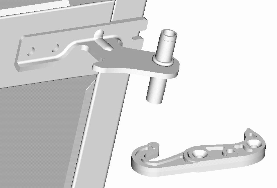
26 FIXING HOLES HINGE BASE INTERMEDIATE HINGE CLOSING STOPPER - FORCED 26

27 INFERIOR HINGE The inferior hinge is fastened under the refrigerator on a metallic reinforcement that allows to give rigidity to the cabinet and at the same time it works like hinge pinning. To carry out the replacement of this hinge the following steps they should be carried out once you have removed the cooler INFERIOR HINGE FIXING door: HOLES 1 - Retire the leveling screw. 2 - Using a 5/16" wrench or Phillips head screwdriver remove the three subjection screws and remove the old hinge. 3 - Place the new hinge using the bores indicated in the figure making sure that the three screws are tightened. 4 - Place the leveling screw again. 5 - Level the refrigerator using both leveling screws and set the apparatus on to make sure that vibration caused by this substitution doesn't exist. LEVELING SCREW HOLE 27
28 TROUBLESHOOTING CHART PROBLEM CAUSE WHAT TO DO Compressor does not operate. 1. Verify Voltage in the plug. (it doesn't emit any noise ). Compressor does not start. (it protects). Compressor starts but immediately protects. The compressor has short cycles. 1. Not enough tension in the plug 2. Power plug pinched. 3. Faulty thermal protector. 4. Inadequate connection. 5. Compressor coil opened. 6. Temperature Control does not work. 7. Control temperature knob in position Defrost control stuck in defrost. 1. Inadequate connection. 2. Low or wrong tension. 3. Compressor short circuit. 4. PTC defective / wrong. 5. Thermal protector wrong. 6. Compressor motor forced. 1. Plug false contact. 2. Clogged tubing. 3. False contact in component connection. 4. Excessive power supply in the thermal. 5. Excessive gas charge. 6. Inadequate Compressor for the unit. 1. Inadequate thermal protector 2. Defective temperature control 3. air flow on the obstructed condenser or dirty condenser. 4. Excessive gas charge. 5. PTC defective. 6. Low Voltage. 2. Replace. 3. Replace. 4. Verify in the diagram. 5. Check continuity of the coil and replace. 6. Replace. 7. Move knob position. 8. Replace. 1. Check connection according to the diagram. 2. Verify voltage and indicate the client to modify his installation. 3. Replace. 4. Replace. 5. Replace. 6. Verify with an amperemeter and replace. 1. Correct plug 2. Replace or unclog the tubing. 3. Strengthen the connection o replace components. 4. Verify electric Diagram. 5. Provide adequate load. 6. Replace right compressor. 1. Replace the right one. 2. Replace. 3. Eliminate obstructions and clean condenser. 4. Provide right charge. 5. Replace. 6. Check voltage and Indicate the client to repair his installation. 28
29 PROBLEM CAUSE SOLUTION The refrigerator does 1. Deficiency of coolant. not shut off. Refrigerator does not cool. 2. Inadequate compressor for the unit. 3. The doors don't close properly. 4. Evaporator blocked. 5. Air flow on the obstructed condenser or dirty condenser. 6. Restriction in the system. 7. Faulty control of temperature. 8. Wrong control of temperature or very cold graduation. 9. Refrigerator exposed to excessive heat. 10. The interior light doesn't turn off. 11. Large amount of foods. 12. Motor fan does not work. 1. Temperature control not calibrated 2. Compressor damaged. 3. Capacity of compressor inferior than required. 4. Gas leak in the system. 5. The motor fan does not work. 6. Reels in wrong position. 7. Excessive frost in the evaporator 8. Air flow on the obstructed condenser or dirty condenser 9. The doors don't close properly 10. Temperature control bulb placed incorrectly 11. Filter or capillary blocked 1. Verify if there is a leak and make the right load. 2. Replace. 3. Adjust doors or replace them if necessary. 4. Defrost and look up the flaw of the blockade. 5. Eliminate obstructions y clean condenser. 6. Restart the system and replace filter. 7. Replace. 8. Replace or change to normal position. 9. Inform the client and change the place. 10. Verify interrupter y correct. 11. Inform the client. 12. Verify the interrupter activates the fan or replace the motor. 1. Calibrate control. 2. Replace. 3. Replace for an adequate. 4. Repair the leak and charge. 5. Verify the interrupter activates the fan or replace the motor. 6. Place the reels correctly. 7. Verify defrost system and correct. 8. Eliminate obstructions and clean condenser. 9. Adjust the doors or replace them if necessary. 10. Change the right position. 11. Restart the system and replace filter. 29
30 PROBLEM CAUSE SOLUTION The refrigerator does not cool in the fresh food compartment but it freezes in excess in the compartment Noise freezer 1. The motor fan does not work. 2. Reels in wrong position. 3. Air duct blocked. 4. Defrost Timer does not work. 5. Defrost Resistance opened. 6. Defrost thermostat opened. 1. Loose fixations. 2. Reel fan produces vibration. 3. Fan cushion worn. 4. Compressor Installed with different shocks. 5. Contact between tubing. 6. Compressor with internal noise. 7. Compressor works with high pressure. SERVICEABLE PARTS 1. Verify the interrupter activates the fan or replace the motor. 2. Place them in the right position. 3. Remove obstructions. 4. Replace. 5. Replace. 6. Replace. 1. Locate and adjust fixation. 2. Replace reel. 3. Replace motor fan. 4. Replace right shocks. 5. Adjust tubes so that they are not in contact among them. 6. Replace 7. Place external muffle. PART No. Description Compressor CBZN122L7G Thermal Protector 4TM408RHBY PTC 8EA D2940P002 Motor fan 186D2838G001 Evaporator 221C7058P001 Defrost Resistance 162D6022P006 Defrost Timer 238C1015P002 Defrost Thermostat 200D3568P003 Temperature control 221C5100P002 Dryer. These numbers of the spare parts can change with the time they are only like reference, to see the total of spare parts and their last update you must refer to the catalog of spare parts and the system of visualization of Serviplus. 30
Service Manual Moffat
 Service Manual Moffat ELECTRONIC POLAR WITH EXTERIOR DISPLAY PUB # 06-MAN/RE-01 MTR12YATWW December, 2006 1 CONTENTS SECURITY DISPLAY FEATURES TEMPERATURE SELECTION QUICK COOLING VACATION LOCK CONTROL
Glass Door Merchandiser. Model RM-45-SD
 Glass Door Merchandiser Model Number: Issued: 02-22-2017 Revised: 02-22-2017 2 TABLE OF CONTENTS UNIT FEATURES 4 Page CROSS SECTION VIEWS 5 EXPLODED VIEW 6, 7 REFRIGERATION SYSTEM 8, 9 CONDENSING UNIT
Glass Door Merchandiser. Model RM-49
 Glass Door Merchandiser Model Number: Issued: 02-22-2017 Revised: 02-22-2017 2 TABLE OF CONTENTS UNIT FEATURES 4 Page CROSS SECTION VIEWS 5 EXPLODED VIEW 6, 7 REFRIGERATION SYSTEM 8, 9 CONDENSING UNIT
Glass Door Merchandiser
 Glass Door Merchandiser Model Number: Issued: 02-22-2017 Revised: 02-22-2017 2 TABLE OF CONTENTS UNIT FEATURES 4 Page CROSS SECTION VIEWS 5 EXPLODED VIEW 6, 7 REFRIGERATION SYSTEM 8, 9 CONDENSING UNIT
Table of Contents. Specifications... page 2. Installation... page 3. Customizing... page 4. Reversing door swing... page 5
 Introduction The Scotsman Compact Refrigerator is a unique product, capable of being built into a cabinet because of its front vented, forced-air cooling system. It s also designed to be a companion to
MANUAL. Instructions for installation use & general maintenance of your HORIZONTAL FREEZER HFF, FLORENCIA and MILAN Product Lines MAN-017-R
 MANUAL Instructions for installation use & general maintenance of your HORIZONTAL FREEZER HFF, FLORENCIA and MILAN Product Lines MAN-017-R LAST REVISION JULY 2009 INDEX Handling... 3 Installation... 4
EBAC MODEL K100 DEHUMIDIFIER OWNER S MANUAL
 EBAC MODEL K100 DEHUMIDIFIER OWNER S MANUAL Ebac Industrial Products 700 Thimble Shoals Boulevard Newport News VA 23606-2575 Telephone (757) 873-6800 Fax (757) 873-3632 Website: www.ebacusa.com INTRODUCTION
Operation Manual SCT14B and SCT18B. Inspection. 3 General Description. 3 General Requirements. 3 Standard Features.
 Spot Cooling Systems, Inc. 120 Century Drive Suite 00 Carrollton, TX 7006 00-6-776 Operation Manual SCT1B and SCT1B Warning! Improper installation, adjustment, alteration, service, or maintenance can cause
UNDERCOUNTER LABORATORY REFRIGERATORS and FREEZERS Installation, Operation and Maintenance Instructions
 UNDERCOUNTER LABORATORY REFRIGERATORS and FREEZERS Installation, Operation and Maintenance Instructions INSPECTION When the equipment is received, all items should be carefully checked against the bill
Product Information and Technical Guide
 Product Information and Technical Guide Side by Side and Top Mount Refrigerators July 2003 - December 2003 White-Westinghouse 5995540384 January 2004 TABLE OF CONTENTS Safe Servicing Practices ------------------------------------------------------------------------------------------
Room Air Conditioner Service and Parts Manual
 Cool Dry Temp Mode Room Air Conditioner Service and Parts Manual F Fan Speed hr Timer 0n 0ff Money Saver Fan Only Auto Swing Power CP06 CP08 93011401_01 CONTENTS 1. PREFACE 1.1 SAFETY PRECAUTIONS...2 1.2
SERVICE MANUAL FOR MODEL RM-10
 SERVICE MANUAL FOR MODEL RM-10 REQUIRED TOOLS CORDLESS DRILL COPPER CUTTING TUBE 1/2 OPEN WRENCH SOLDERING IRON SCREWDRIVER SET WITH 9/32 SOCKET VISE GRIP PIERCING VALVE PRECISION FLAT BLADE SLOTTED SCREWDRIVER
ICE CREAM TOPPING CABINETS REFRIGERATOR or FREEZER Installation, Operation and Maintenance Instructions
 ICE CREAM TOPPING CABINETS REFRIGERATOR or FREEZER Installation, Operation and Maintenance Instructions INSPECTION When the equipment is received, all items should be carefully checked against the bill
PHOENIX 200 MAX. 1 Specifications. 2 Operation. Therma-Stor Products. Phoenix 200 Max Operation & Service Instructions
 PHOENIX 200 MAX LOW GRAIN REFRIGERANT HIGH CAPACITY DEHUMIDIFIER Table of Contents Therma-Stor Products Box 8050 Madison, WI 53708 Toll Free 1-800-533-7533 Local 1-608-222-5301 Phoenix 200 Max Operation
EBAC MODEL CD30 INDUSTRIAL DEHUMIDIFIER OWNER S MANUAL
 EBAC MODEL CD30 INDUSTRIAL DEHUMIDIFIER OWNER S MANUAL Ebac Industrial Products 704 Middle Ground Boulevard Newport News, VA 23606 Tel: 757 873 6800 Fax: 757 873 3632 Website: www.ebacusa.com UNPACKING
Installation, Operation, and Maintenance Information
 Installation, Operation, and Maintenance Information Low Velocity Unit Coolers Bulletin No. IOM 110.3 Table of Contents Inspection... 2 Installation... 2 4 General... 2 Location... 2 Drain Line... 3 Refrigerant
SERVICE MANUAL FOR MODEL RM-49
 SERVICE MANUAL FOR MODEL RM-49 REQUIRED TOOLS CORDLESS DRILL DRIVE CUTTING TUBING OPEN WRENCH OF 1/2 RATCHET WITH SOCKET OF 7/16 SCREWDRIVER SET WITH SOCKET OF 9/32 VISE GRIP PIERCING VALVE WATCHER SLOTTED
GENERAL LABORATORY REFRIGERATORS AND FREEZERS Installation, Operation and Maintenance Instructions
 GENERAL LABORATORY REFRIGERATORS AND FREEZERS Installation, Operation and Maintenance Instructions INSPECTION When the equipment is received, all items should be carefully checked against the bill of lading
Product Information and Technical Guide
 Product Information and Technical Guide Side by Side and Top Mount Refrigerators January 2004 - March 2004 White-Westinghouse 5995413308 July 2004 TABLE OF CONTENTS Safe Servicing Practices ------------------------------------------------------------------------------------------
TECHNICIAN'S MANUAL 1989 REFRIGERATORS MODELS BCS42CKB/C BCS42EK BCS42EL BIS42CKB/C BISB42EK BISW42EK BISB42EL BISW42EL HOTPOINT
 GENERAL ELECTRIC REFRIGERATORS AND FREEZERS HOTPOINT TECHNICIAN'S MANUAL BIS42CKB/C BISB42EK BISW42EK BISB42EL BISW42EL MODELS BCS42CKB/C BCS42EK BCS42EL General Electric Co. 1989 Pub. No. 31-5214 GENERAL
Full Size Canister Service Manual Riccar Models 1700 / 1800 Power Nozzles RPB-100 / RPB-220 / RPB-224 / RPB-250
 Full Size Canister Service Manual Riccar Models 1700 / 1800 Power Nozzles RPB-100 / RPB-220 / RPB-224 / RPB-250 Table of Contents I. General Full Size Canister Issues...2 A. Full Bag Indicator...2 1. General
Refrigeration System with a Capillary Tube and a Thermostat
 Exercise 2-1 Refrigeration System with a Capillary Tube Part A: REFRIGERATION CIRCUIT OBJECTIVE When you have completed this part, a refrigeration circuit using a capillary tube as a metering device will
COMMERCIAL REFRIGERATOR & FREEZER SERVICE MANUAL (SCL/SCLM)
") COMMERCIAL REFRIGERATOR & FREEZER SERVICE MANUAL (SCL/SCLM) MODEL: SCL1 SCL2 SCL2-36 SCL2-60 SCL3 SCLM1 SCLM2 SCLM2-36 SCLM2-60 SCLM3 TABLE OF CONTENTS 1. EXPLODED VIEW AND PARTS LIST... 3 1.1 SCL1 & SCLM1...
COMMERCIAL REFRIGERATOR & FREEZER SERVICE MANUAL (SCL/SCLM) MODEL: SCL1 SCL2 SCL2-36 SCL2-60 SCL3 SCLM1 SCLM2 SCLM2-36 SCLM2-60 SCLM3 TABLE OF CONTENTS 1. EXPLODED VIEW AND PARTS LIST... 3 1.1 SCL1 & SCLM1...
InstructIon Manual KrEs EQuIPMEnt stands
 Instruction Manual Instruction Manual SELF-CONTAINED AND REMOTE Kairak KRES model refrigerated equipment stand units are available in many lengths from 36 to 120 inches long. These units are available
SERVICE MANUAL REFRIGERATION
 SERVICE MANUAL REFRIGERATION ELECTROLUX HOME PRODUCTS S.p.A. Publication no. Spares Operations Italy 599 37 75-07 Corso Lino Zanussi, 30 060824 I - 33080 PORCIA / PN (ITALY) ITZ/SERVICE/AA Fax +39 0434
User Manual. Commercial Refrigerator And Freezer User s Manual
 User Manual Commercial Refrigerator And Freezer User s Manual 05/2016 Reach-in Refrigerator And Freezer Refrigerator model: CFD-1RR, CFD-2RR, CFD-3RR Freezer model: CFD-1FF, CFD-2FF, CFD-3FF Glass Door
APARTMENT MAINTENANCE SERIES
 ORPORATION CONSUMER SERVICES TECHNICAL EDUCATION GROUP PRESENTS AM-4 APARTMENT MAINTENANCE SERIES TOP-MOUNT REFRIGERATOR/FREEZERS OLD DESIGN 14 cu. ft. MULLION EVAPORATOR DESIGN 12 cu. ft. NEW DESIGN 14
Service Manual For electronic dual temperature zone wine cellar Includes DWC282 / 283
 Service Manual For electronic dual temperature zone wine cellar Includes DWC282 / 283 2 / 18 This is a service guideline for possible failure and repair. Warning: before attempting any cleaning or maintenance
SERVICE MANUAL FOR MODEL RM-26
 SERVICE MANUAL FOR MODEL RM-26 REQUIRED TOOLS CORDLESS DRILL DRIVE CUTTING TUBING OPEN WRENCH OF 1/2 RATCHET WITH SOCKET OF 7/16 SCREWDRIVER SET WITH SOCKET OF 9/32 VISE GRIP PIERCING VALVE WATCHER SLOTTED
5) Do not start or stop the unit by inserting or pulling out the power plug.
 Do not start or stop the unit by inserting or pulling out the power plug.") 3058080 V170306 PURCHASE INFORMATION Thank you for choosing a Soleus Air Portable Air Conditioner. This Owner s Manual will provide you with valuable information necessary for the proper care and maintenance
3058080 V170306 PURCHASE INFORMATION Thank you for choosing a Soleus Air Portable Air Conditioner. This Owner s Manual will provide you with valuable information necessary for the proper care and maintenance
1 Specifications. 2 Operation. PHOENIX 300 Operation & Service Instructions. 2.1 Transporting the Phoenix. 2.2 Location
 Therma-Stor Products A Division of DEC International Box 8050 Madison, WI 53708 Toll Free 1-800-533-7533 Local 1-608-222-5301 PHOENIX 300 Operation & Service Instructions Table of Contents 1. Specifications...
Electrical Problems. Fuse(s) blow or circuit breaker trips. Does the unit use circuit breakers or fuses? Replace with correct fuse(s)
 blow or circuit breaker trips. Does the unit use circuit breakers or fuses? Replace with correct fuse(s)") Electrical Problems Fuse(s) blow or circuit breaker trips Does the unit use circuit breakers or fuses? Fuse(s) Circuit breakers Are the fuses dual element time delay? Is the circuit breaker HACR rated?
Electrical Problems Fuse(s) blow or circuit breaker trips Does the unit use circuit breakers or fuses? Fuse(s) Circuit breakers Are the fuses dual element time delay? Is the circuit breaker HACR rated?
Installation and User's Manual for Refrigerator Model SCR33
 Installation and for Refrigerator Model SCR33 Introduction Congratulations on your purchase of a Scotsman refrigeration product. For future reference, keep this guide in a safe, accessible location. If
POLAR TEMP FARM MORTALITY UNIT OPERATION MANUAL
 POLAR TEMP FARM MORTALITY UNIT OPERATION MANUAL www.polartemp.com TABLE OF CONTENT Disclaimer.......................................... Page 3 Inspection, unpacking and FMU setup.................. Page
12,000 BTU Evaporative Portable Air Conditioner
 12,000 BTU Evaporative Portable Air Conditioner Owner s Manual Model # KY-32E Please read owner s manual carefully before operating the unit. TABLE OF CONTENTS PAGE Table of Contents. 2 Introduction....3
REFRIGERATORS AND FREEZERS Installation, Operation and Maintenance Instructions
 REFRIGERATORS AND FREEZERS Installation, Operation and Maintenance Instructions INSPECTION When the equipment is received, all items should be carefully checked against the bill of lading to insure all
Portable Air Conditioner 6,000 BTU 8,000 BTU 10,000 BTU
 Portable Air Conditioner 6,000 BTU 8,000 BTU 10,000 BTU OPERATING INSTRUCTIONS PCR-06-01 PCR-08-01 PCR-10-01 3058080 V170223 PURCHASE INFORMATION Thank you for choosing a Chigo Portable Air Conditioner.
UPRIGHT FREEZER WHS-502FWEW1(E) WHS-502FWEB1(E) WHS-502FWESS1(E)
 WHS-502FWEB1(E) WHS-502FWESS1(E)") UPRIGHT FREEZER WHS-502FWEW1(E) WHS-502FWEB1(E) WHS-502FWESS1(E) TABLE OF CONTENTS NAMES OF THE PARTS.2 IMPORTANT SAFETY INSTRUCTIONS..3 INSTALLATION INSTRUCTION BEFORE USING YOUR FREEZER...3 INSTALLING
UPRIGHT FREEZER WHS-502FWEW1(E) WHS-502FWEB1(E) WHS-502FWESS1(E) TABLE OF CONTENTS NAMES OF THE PARTS.2 IMPORTANT SAFETY INSTRUCTIONS..3 INSTALLATION INSTRUCTION BEFORE USING YOUR FREEZER...3 INSTALLING
SERVICE MANUAL REFRIGERATION
 SERVICE MANUAL REFRIGERATION Electrolux Home Products S.p.A. Spares Operations Italy Corso lino Zanussi, 30 I - 33080 Porcia (PN) Fax +39 0434 394096 S.O.I. Edition: 10.2006 Publication no. 599 38 38-50
Product Information and Technical Guide
 Product Information and Technical Guide Side by Side and Top Mount Refrigerators January 2005 - June 2005 White-Westinghouse 5995449906 October 2005 TABLE OF CONTENTS Safe Servicing Practices ------------------------------------------------------------------------------------------
EBAC MODEL CD425 ( ) INDUSTRIAL DEHUMIDIFIER OWNER S MANUAL
 INDUSTRIAL DEHUMIDIFIER OWNER S MANUAL") EBAC MODEL CD425 (1018110) INDUSTRIAL DEHUMIDIFIER OWNER S MANUAL Ebac Industrial Products 704 Middle Ground Boulevard Newport News, VA 23606 Tel: 757 873 6800 Fax: 757 873 3632 Website: www.ebacusa.com
EBAC MODEL CD425 (1018110) INDUSTRIAL DEHUMIDIFIER OWNER S MANUAL Ebac Industrial Products 704 Middle Ground Boulevard Newport News, VA 23606 Tel: 757 873 6800 Fax: 757 873 3632 Website: www.ebacusa.com
1. SAFETY WARNINGS INSTALLTION Location Reversing the Door Swing Levelling the Unit... 3
 Contents 1. SAFETY WARNINGS... 1 2. INSTALLTION... 2 2.1 Location... 2 2.2 Reversing the Door Swing... 2 2.3 Levelling the Unit... 3 2.4 Cleaning Before Use... 3 2.5 Before Using Your Unit... CE BC108
Product Information and Technical Guide
 Product Information and Technical Guide Side by Side and Top Mount Refrigerators April 2004 - December 2004 White-Westinghouse 5995427241 January 2005 TABLE OF CONTENTS Safe Servicing Practices ------------------------------------------------------------------------------------------
442 Chapter 16. Figure 16-5 Gas leak detection
 BRORANE BRORANEBRORANEBRORANEBRORANEBRORANEBRORANEBRORANE 442 Chapter 16 Tur n e r BRORANE FUEL EBRORANEBRORANEBRORANEBRORANEBRORANE Figure 16-5 Gas leak detection is easy. This sensitive halide detector
FROST FREE REFRIGERATOR INSTRUCTION MANUAL
 FROST FREE REFRIGERATOR INSTRUCTION MANUAL Model No.: MCBR1010W MCBR1010S To ensure proper use of this appliance and your safety, please read the following instructions completely before operating this
EBAC MODEL WM150 INDUSTRIAL DEHUMIDIFIER OWNER S MANUAL
 EBAC MODEL WM150 INDUSTRIAL DEHUMIDIFIER OWNER S MANUAL WM150 OWNERS MANUAL Page 1 of 9 INTRODUCTION Designed for a wide range of applications, the WM150 is a rugged, industrial unit, which utilizes an
HOUSEHOLD FREEZER 048-GM-48303/048-GM-48304/048-GM-48305
 HOUSEHOLD FREEZER 048-GM-48303/048-GM-48304/048-GM-48305 TABLE OF CONTENTS NAMES OF THE PARTS 2 IMPORTANT SAFETY INSTRUCTIONS 3 INSTALLATION INSTRUCTIONS BEFORE USING YOUR FREEZER. 3 INSTALLING YOUR FREEZER
SECTION 8 AIR SOURCE HEAT PUMPS UNIT 43 AIR SOURCE HEAT PUMPS
 SECTION 8 AIR SOURCE HEAT PUMPS UNIT 43 AIR SOURCE HEAT PUMPS UNIT OBJECTIVES After studying this unit, the reader should be able to Describe the operation of reverse-cycle refrigeration (heat pumps) Explain
CD30 / CD30E DEHUMIDIFIER (FULL PRODUCT RANGE) OWNER S MANUAL
 OWNER S MANUAL") CD30 / CD30E DEHUMIDIFIER (FULL PRODUCT RANGE) OWNER S MANUAL www.eipl.co.uk Page 1 of 16 UNPACKING Carefully remove the CD30 dehumidifier unit from its transit box and visually check for signs of transit
CD30 / CD30E DEHUMIDIFIER (FULL PRODUCT RANGE) OWNER S MANUAL www.eipl.co.uk Page 1 of 16 UNPACKING Carefully remove the CD30 dehumidifier unit from its transit box and visually check for signs of transit
HEATING AND VENTILATION
 SECTION 14-102.04 14-102.04/ 1 2007OC19 DESCRIPTION The heating, ventilation and air conditioning (HVAC) system is designed to optimize passenger comfort. The system regulates interior vehicle atmosphere,
G-7s. Instruction Manual. G-Series Cooler COUNTERTOP COOLER. Part No.11IPA
 G-Series Cooler COUNTERTOP COOLER Part No.11IPA-061000 Instruction Manual FOR YOUR FUTURE REFERENCE This easy-to-use manual will guide you in getting the best use of your cooler. Remember to record the
FTM419A01W USER S MANUAL FROST FREE REFRIGERATOR
 FROST FREE REFRIGERATOR USER S MANUAL FTM419A01W Please read the manual carefully before operation and keep it for reference. This manual is only for reference, please comply with actual appliance you
NOTICE . SAFE SERVICING PRACTICES. Electric Wall Oven with Electronic Oven Control
 SERVICE DATA SHEET 318047418 (0504) Rev. A Electric Wall Oven with Electronic Oven Control NOTICE This service data sheet is intended for use by persons having electrical and mechanical training and a
Service Manual & Installation Manual
 GE Consumer & Industrial Appliances Service Manual & Installation Manual Split System Air Conditioner Model numbers: GE AIR F24 GE AIR F34 GE AIR F41 1 2 3 Introduction and Features Model Remarks GE AIR
Room Air Conditioner SERVICE MANUAL MODEL : LW6013ERY3. CAUTION
 www.zenithappliances.com Room Air Conditioner SERVICE MANUAL MODEL : LW6013ERY3 CAUTION BEFORE SERVICING THE UNIT, READ THE SAFETY PRECAUTIONS IN THIS MANUAL. ONLY FOR AUTHORIZED SERVICE PERSONNEL. CONTENTS
REFRIGERATOR SAFETY. Your safety and the safety of others are very important.
 REFRIGERATOR SAFETY Your safety and the safety of others are very important. We have provided many important safety messages in this manual for your appliance. Always read and obey all safety messages.
INSTALLATION INSTRUCTIONS FOR MOUNTING KIT
 RV Products Division INSTALLATION INSTRUCTIONS FOR 8330-5501 MOUNTING KIT 8330-752 CONTROL BOX KIT (12 VDC COOL ONLY) 9330B755 CONTROL BOX KIT (12 VDC HEAT/COOL) 8530-750 CONTROL BOX KIT (24 VAC COOL ONLY)
INSTALLATION INSTRUCTIONS FOR 8330*5511 MOUNTING KIT
 RV Products Division INSTALLATION INSTRUCTIONS FOR 8330*5511 MOUNTING KIT 8330-752 CONTROL BOX KIT (12 VDC COOL ONLY) 9330A755 CONTROL BOX KIT (12 VDC HEAT/COOL) 8530-750 CONTROL BOX KIT (24 VAC COOL ONLY)
CHEST FREEZER INSTRUCTION MANUAL. Model No.: EWCF5WBX EWCF7WBX
 CHEST FREEZER INSTRUCTION MANUAL Model No.: EWCF5WBX EWCF7WBX To ensure proper use of this appliance and your safety, please read the following instructions completely before operating this appliance.
INSTALLATION and OPERATING. INSTRUCTIONS for. SMZP26 Series. elf-contained Freezers
 S elf-contained Freezers INSTALLATION and OPERATING INSTRUCTIONS for Series ZERO ZONE Zero Zone, Inc. 110 N. Oakridge Dr. North Prairie, WI 53153-9792 1-800-247-4496 FAX: 1-414-392-6450 www.zero-zone.com
EBAC MODEL CD30 INDUSTRIAL DEHUMIDIFIER OWNER S MANUAL
 EBAC MODEL CD30 INDUSTRIAL DEHUMIDIFIER OWNER S MANUAL Ebac Industrial Products, Inc. 700 Thimble Shoals Blvd, Suite 109 Newport News, VA. 23606-2575 Tel: (757) 873 6800 Fax: (757) 873 3632 Website www.ebacusa.com
Glass Door Undercounter and Countertop Freezers
 To better help you obtain assistance or service should you ever need it, write down the following information about the product. This information is on the identification label located on the left hand
Glass Door Merchandisers GDC10, GDC12F, GDC15, GDC23, GDC24F, GDC40, GDC40F, GDS47, GDC69
 Commercial Refrigerator And Freezer User s Manual Glass Door Merchandisers GDC10, GDC12F, GDC15, GDC23, GDC24F, GDC40, GDC40F, GDS47, GDC69 12/2015 Please read the manual thoroughly prior to equipment
G-10s. Instruction Manual. G-Series Cooler UPRIGHT COOLER. Part No.11IPA
 G-Series Cooler UPRIGHT COOLER Part No.11IPA-062800 Instruction Manual FOR YOUR FUTURE REFERENCE Thank you for using our product. This manual will guide you in getting the best use of your cooler. Remember
3500 SERIES CONVECTION STEAM COOKER PARTS AND SERVICE MANUAL
 3500 SERIES CONVECTION STEAM COOKER PARTS AND SERVICE MANUAL EFFECTIVE JULY 30, 2014 Superseding All Previous Parts Lists. The Company reserves the right to make substitution in the event that items specified
1 SAFETY REPAIR COMPONENTS FUNCTIONS FAULT DIAGNOSIS X-Cool Side by Side Refrigerator
 1 SAFETY... 3 1.1 Safety instructions... 3 1.2 Repair instructions... 3 2 COMPONENTS... 4 2.1 Overall view... 4 2.2 Compressor room... 4 2.3 Power Control Boards (PCB)... 5 2.4 Temperature sensor... 6
Model No.: PS08-01 PS10-01 Ref: KY80 KY100
 8,000/10,000/12,000 BTU Portable Air Conditioner Operating Instructions Model No.: PS08-01 PS10-01 Ref: KY80 KY100 Model No.: PS12-03 Ref: KY120 3119233 V160310 Thank you for choosing a Soleus Air Portable
STRUCTURE ILLUSTRATION...3 IMPORTANT SAFETY INSTRUCTIONS 4 INSTALLATION INSTRUCTION..4 OPERATING YOUR REFRIGERATOR...5-6
 TABLE OF CONTENTS STRUCTURE ILLUSTRATION....3 IMPORTANT SAFETY INSTRUCTIONS 4 INSTALLATION INSTRUCTION..4 OPERATING YOUR REFRIGERATOR...5-6 FREEZER COMPARTMENT OPERATION 6 CARE & MAINTENANCE..7 CHANGING
4.5 CU.FT. REFRIGERATOR INSTRUCTION MANUAL
 4.5 CU.FT. REFRIGERATOR INSTRUCTION MANUAL Model No.: MCBR465S To ensure proper use of this appliance and your safety, please read the following instructions completely before operating this appliance.
TECHNICAL & SERVICE MANUAL WINDOW TYPE AIR CONDITIONER SA 123A FILE NO. SA 123A REFERENCE NO. SM700513
 TECHNICAL & SERVICE MANUAL SA 123A FILE NO. WINDOW TYPE AIR CONDITIONER Model No. Product Code No. Destination SA-123A 1 851 006 95 Australia SA 123A REFERENCE NO. SM700513 IMPORTANT! Please Read Before
T-SERIES Air Conditioner. T50 Model INSTRUCTION MANUAL nvent Rev. F P/N
 T-SERIES Air Conditioner T50 Model INSTRUCTION MANUAL Rev. F P/N 10-1008-203 TABLE OF CONTENTS Warranty and Return Policy...2 RECEIVING THE AIR CONDITIONER...3 HANDLING AND TESTING THE AIR CONDITIONER...3
KAR-5 TECHNICAL EDUCATION KUWS246 WINE CELLAR JOB AID
 KAR-5 TECHNICAL EDUCATION KUWS246 WINE CELLAR I JOB AID 4317201 INTRODUCTION This Job Aid, KUWS246 WINE CELLAR, (Part No. 4317201), has been compiled to provide the most recent information on design, features,
INSTRUCTION MANUAL (UNIT APPEARANCE MAY VARY FROM IMAGE) BEFORE USE, PLEASE READ AND FOLLOW ALL SAFETY RULES AND OPERATING INSTRUCTIONS.
 BEFORE USE, PLEASE READ AND FOLLOW ALL SAFETY RULES AND OPERATING INSTRUCTIONS.") INSTRUCTION MANUAL Model Number: FR551 REFRIGERATOR-FREEZER (UNIT APPEARANCE MAY VARY FROM IMAGE) BEFORE USE, PLEASE READ AND FOLLOW ALL SAFETY RULES AND OPERATING INSTRUCTIONS. Igloo has a policy of continuous
INSTRUCTION MANUAL Model Number: FR551 REFRIGERATOR-FREEZER (UNIT APPEARANCE MAY VARY FROM IMAGE) BEFORE USE, PLEASE READ AND FOLLOW ALL SAFETY RULES AND OPERATING INSTRUCTIONS. Igloo has a policy of continuous
KELVINATOR C O M M E R C I A L COMMERCIAL FREEZER/REFRIGERATOR REACH-IN REFRIGERATOR AND FREEZER. Refrigerator Model: KCBM23R, KCBM48R, KCBM72R
 KELVINATOR C O M M E R C I A L COMMERCIAL FREEZER/REFRIGERATOR REACH-IN REFRIGERATOR AND FREEZER Refrigerator Model: KCBM23R, KCBM48R, KCBM72R Freezer Model: KCBM23F, KCBM48F TABLE OF CONTENTS Product
Wine Cooler. Model No. MCWC16MCG MCWC30MCG. CAUTION: Read and follow all safety rules and operating instructions before first use of this product.
 Wine Cooler Model No. MCWC16MCG MCWC30MCG Wine Cooler. Before Putting Into Use.................. Important......................... Placing and Installation.................. Description of the Appliance................
TECHNICAL & SERVICE MANUAL WINDOW TYPE AIR CONDITIONER SA 183A FILE NO. SA 183A REFERENCE NO. SM Destination Australia SA-183A
 TECHNICAL & SERVICE MANUAL SA 183A FILE NO. WINDOW TYPE AIR CONDITIONER Model No. Product Code No. SA-183A 1 851 006 96 Destination Australia SA 183A REFERENCE NO. SM700514 IMPORTANT! Please Read Before
SERVICE MANUAL VC3ED FULL SIZE ELECTRIC CONVECTION OVEN - NOTICE -
 SERVICE MANUAL VC3ED FULL SIZE ELECTRIC CONVECTION OVEN VC3ED ML-137013 - NOTICE - This Manual is prepared for the use of trained Vulcan Service Technicians and should not be used by those not properly
Component. Maintenance. Manual Z SERIES. Evaporator Assembly
 Component Maintenance Manual with Illustrated Parts List for Z21-701-SERIES Evaporator Assembly 1 of 16 Record of Revision REVISION ISSUE POSTED NO: DATE DATE INSERTED BY: 2 of 16 List of Effective Pages
TCW 2000 Ice liner refrigerator and freezer PIJ
 TCW 2000 Ice liner refrigerator and freezer OVER VIEW The unique rotomoulded Chest Freezer and inclined Refrigerator with two separate compartments and compressors worldwide Hold over time @ 32 C Hold
Model No. GB-PAC-08E4. 8,000 BTU Portable Air Conditioner Operating Instructions
 Model No. GB-PAC-08E4 8,000 BTU Portable Air Conditioner Operating Instructions Thank you for choosing a Soleus Air Powered by Gree Portable Air Conditioner. This owner s manual will provide you with valuable
PERFECT FIT IN-DASH HEAT/ COOL/ DEFROST FORD PICKUP
 specializing in AIR CONDITIONING, PARTS AND SYSTEMS for your classic vehicle PERFECT FIT IN-DASH HEAT/ COOL/ DEFROST 1960-66 FORD PICKUP CONTROL & OPERATING INSTRUCTIONS The controls on your new Perfect
RCM-77. Instruction Manual. G-Series Cooler. U.S. Patent No. 8,215,125 RECHARGE COLD MERCHANDISER
 G-Series Cooler RECHARGE COLD MERCHANDISER U.S. Patent No. 8,215,125 Instruction Manual FOR YOUR FUTURE REFERENCE This easy-to-use manual will guide you in getting the best use of your cooler. Remember
T-SERIES Air Conditioner. T43 Model INSTRUCTION MANUAL nvent Rev. I P/N
 T-SERIES Air Conditioner T43 Model INSTRUCTION MANUAL Rev. I P/N 10-1008-145 TABLE OF CONTENTS Warranty and Return Policy...2 IMPORTANT NOTICE...2 RECEIVING THE AIR CONDITIONER...3 HANDLING AND TESTING
9.9 CU.FT. TOP MOUNT REFRIGERATOR INSTRUCTION MANUAL. Model No.: HVDR1040W HVDR1040B HVDR1040S
 9.9 CU.FT. TOP MOUNT REFRIGERATOR INSTRUCTION MANUAL Model No.: HVDR1040W HVDR1040B HVDR1040S To ensure proper use of this appliance and your safety, please read the following instructions completely before
REF5-BB Undercounter Blood Bank Refrigerator
 REF5-BB Undercounter Blood Bank Refrigerator Order parts online www.follettice.com Installation, Operation and Service Manual Following installation, please forward this manual to the appropriate operations
T-SERIES Air Conditioner. T20 Model INSTRUCTION MANUAL nvent Rev. C P/N
 T-SERIES Air Conditioner T20 Model INSTRUCTION MANUAL Rev. C P/N 89114993 TABLE OF CONTENTS Warranty and Return Policy... 2 IMPORTANT NOTICE... 2 RECEIVING THE AIR CONDITIONER... 3 HANDLING AND TESTING
T-Series Air Conditioner T53 Model
 INSTRUCTION MANUAL T-Series Air Conditioner T53 Model Protecting Electronics. Exceeding Expectations. McLean Cooling Technology 11611 Business Park Blvd N Champlin, MN 55316 USA Tel 763-323-8200 Fax 763-576-3200
CAREFULLY READ THESE INSTRUCTIONS BEFORE USING SAFETY PRECAUTIONS USE OF EXTENSION CORDS
 Owner s Manual CR2500ACH CR5000ACH Portable Heating and Air Conditioning Unit Version 02 Table of Contents 1. SAFETY INSTRUCTIONS... 1-1 CAREFULLY READ THESE INSTRUCTIONS BEFORE USING... 1-1 SAFETY PRECAUTIONS...
CABINET PARTS For Models: ED25UEXHW01, ED25UEXHT01 (White) (Biscuit)
 (Biscuit)") CABINET PARTS REFRIGERATOR 9 00 Litho In U.S.A. (dmz) 1 Part No. CABINET PARTS 1 LIT2205958 Use & Care Guide LIT2204338 Service & Wiring Sheet LIT2211832 Energy Guide LIT628370 Modular Icemaker Service
CABINET PARTS REFRIGERATOR 9 00 Litho In U.S.A. (dmz) 1 Part No. CABINET PARTS 1 LIT2205958 Use & Care Guide LIT2204338 Service & Wiring Sheet LIT2211832 Energy Guide LIT628370 Modular Icemaker Service
11,000 BTU Portable Air Conditioner with dehumidifier & Fan PE4-11R-03 Operating Instructions. Model No. PE4-11R Soleus Air International
 11,000 BTU Portable Air Conditioner with dehumidifier & Fan PE4-11R-03 Operating Instructions Model No. PE4-11R-03 2006 Soleus Air International Thank you for choosing a Soleus Air Portable Air Conditioner.
GCG-9. Instruction Manual. G-Series Cooler. Manual is for the following models: GCG-9-N13EB G-9-N13EB GCG-9-B13EB UPRIGHT COOLER
 G-Series Cooler UPRIGHT COOLER Manual is for the following models: -N13EB G-9-N13EB -B13EB Instruction Manual FOR YOUR FUTURE REFERENCE This easy-to-use manual will guide you in getting the best use of
GCG-10. Instruction Manual. G-Series Cooler. Manual is for the following models: GCG-10-N33EB G-10-N33EB UPRIGHT COOLER
 G-Series Cooler GCG-10 UPRIGHT COOLER Manual is for the following models: GCG-10-N33EB G-10-N33EB Instruction Manual Manual is for the following models: GCG-10-N33EB G-10-N33EB Instruction Manual GCG-10
T-Series Air Conditioner T20 Model
 INSTRUCTION MANUAL T-Series Air Conditioner T20 Model Protecting Electronics. Exceeding Expectations. McLean Cooling Technology 11611 Business Park Blvd N Champlin, MN 55316 USA Tel 763-323-8200 Fax 763-576-3200
Heat Pump Water Heater. Table of Contents
 Table of Contents INTRODUCTION... 3 SAFETY... 3 Electrical... 3 R410a Refrigerant... 3 Scalding... 3 Flammable Vapors... 3 COMPONENT PARTS OF THE HEAT PUMP WATER HEATER... 4 TOOLS... 10 OPERATIONAL MODES...
POLAR TEMP XPORTABLE ICE MERCHANDISER SETUP MANUAL
 POLAR TEMP XPORTABLE ICE MERCHANDISER SETUP MANUAL www.polartemp.com TABLE OF CONTENTS Disclaimer.......................................... Page 3 Inspection and unpacking..............................
INSTRUCTION MANUAL. Model Number: DX K Wine Cooler BEFORE USE, PLEASE READ AND FOLLOW ALL SAFETY RULES AND OPERATING INSTRUCTIONS.
 INSTRUCTION MANUAL Model Number: DX-48.130K Wine Cooler CAUTION: BEFORE USE, PLEASE READ AND FOLLOW ALL SAFETY RULES AND OPERATING INSTRUCTIONS. TABLE OF CONTENTS 1. WINE COOLER SAFETY...114 2. IMPORTANT
Manual / Handbuch Spare parts list / Ersatzteilliste
 Manual / Handbuch Spare parts list / Ersatzteilliste Equipment Imp.-Exp. GmbH Zitterpappelweg 9 D - 22391 Hamburg Tel.: + 49 40 60009468-0 Fax: + 49 40 536 75 01 E - M a i l : i n f o @ w e s c o - n a
Installation Instructions
 Installation Instructions KFN 9855 ide en - CA Installation, repair and maintenance work should be performed by a Miele authorized service technician in accordance with national and local safety regulations
MSPA-MP METAPACK SERVICE MANUAL. Visual step-by-step guide to easily identify & correct technical problems! Gecko Electronics Inc.
 MSPA-MP METAPACK SERVICE MANUAL Gecko Electronics Inc. Visual step-by-step guide to easily identify & correct technical problems! Table of Contents Power & Ground Check Tools and Parts 3 Electrical Wiring
XPS-ProDry User s Guide Dryer Base
 XPS-ProDry User s Guide XPS-ProDry User s Guide Dryer Base For Use with Inkjet Imaging Systems Manual Part#: M-3120 Revision: August 2005 XPS-ProDry User s Guide Written by Frank Mauri & John Brand Published