SV Series Spa Controls Installation & Technical Manual SV2 / SV2-VH / SV3 / SV3-VH / SV4-VH
|
|
|
- Hilary Anderson
- 5 years ago
- Views:
Transcription


1 Installation & Technical Manual SV2 / SV2-VH / SV3 / SV3-VH / SV4-VH
2 Table of Contents SYSTEM OVERVIEW Safety Warnings... 1 Specification Sheet... 2 Component Overview... 3 Spa Pack Dimensions... 4 SV2.T Keypad Dimensions... 5 SV3.T / SV4.T Keypad Dimensions... 6 INSTALLATI PROCEDURES Floor mount spa pack installation... 7 Wall mount spa pack installation... 8 Keypad installation (all models)... 9 Keypad cut-out template Electrical Wiring (terminal block connections) Dip Switch settings Pump Configurations P Power Outlets (240V) Low Voltage Outlets (12V) Heat Pump Installation OEM PROGRMABLE OPTIS Program circuit breaker rating (current limit) OEM configuration menu Diagnostics menu Contact Us i
3 ! WARNINGS Please read the following before installing or connecting this appliance RISK OF ELECTRICAL SHOCK All electrical connections must be performed by a licensed electrician and must confirm to all national, state and local electrical codes in effect at the time of installation. The appliance should be supplied through a residual current device (RCD) having a rated residual operating current not exceeding 30mA. The appliance must be connected to a suitable rated and weather protected power supply. The supply line should be a dedicated power circuit and means for disconnection must be incorporated in the fixed wiring in accordance with your local wiring regulations. Means for disconnection from the supply mains should have a contact separation in all poles that provide full disconnection under over voltage Category III conditions. Earthed appliances must be permanently connected to fixed wiring (European models only). The appliance contains no serviceable parts. Do not attempt service of this control pack. Contact your dealer or authorized service agent for assistance. Turn the mains power before servicing appliance or modifying any cable connection Suitable for indoor use only or when installed under a weatherproof spa skirt. The appliance should be installed in an enclosure such that all electrical connections cannot be accessible to the user without the use of a tool. To prevent electric shock hazard and/or water damage to this appliance, all unused receptacles must have a water proof seal in place. Parts incorporating electrical components must be located or fixed so that they cannot fall into the bath or spa. Parts containing live parts, except parts supplied with safety extra-low voltage not exceeding 12V must be inaccessible to a person in the bath or spa. This appliance must not be installed in proximity to highly flammable materials. o Water temperature in excess of 38 C may cause hyperthermia (heat stress). It is the spa manufacturer's and/or installer's responsibility to select suitable loads and configure load shed settings (if required) to ensure the system does not exceed its rated maximum total load. It is the installer's responsibility to ensure the floor is capable of supporting the expected load of the bath or spa and an adequate drainage system has to be provided to deal with overflow water. A whirlpool spa should incorporate a water filtration system where the required level of water purity can be achieved. An adequate drainage system has to be provided if the equipment is to be installed in a pit. Low voltage or improper wiring may cause damage to this appliance. Read and follow all wiring instructions when connecting to power supply. Any damaged cable must be replaced immediately. 1 This appliance is not intended for use by persons (including children) with reduced physical, sensory or mental capabilities, or lack of experience and knowledge, unless they have been given supervision or instruction concerning use of the appliance by a person responsible for their safety. Children should be supervised to ensure that they do not play with the appliance.
 SV2 15A - 230-240V AC 400-415V AC 50/60 2kW SV3 45A - 230-240V AC 400-415V AC 50/60 3kW SV2-VH 15A 16A per phase 230-240V AC 400-415V AC 50/60 3kW Variable")
 Dimensions (with")
4 SV Series Specifications Electrical Specifications Model No Max Maximum Multi Input Voltage Input Voltage Hz Heater Size Current Phase Current Single Phase* Three Phase* System Specifications All Models (SV2/SV3/SV2-VH/SV3-VH/SV4-VH) SV2 15A V AC V AC 50/60 2kW SV3 45A V AC V AC 50/60 3kW SV2-VH 15A 16A per phase V AC V AC 50/60 3kW Variable SV3-VH 45A 25A per phase V AC V AC 50/60 6kW Variable SV4-VH 60A 25A per phase V AC V AC 50/60 6kW Variable * Range of acceptability (+/-6%) Output Ratings Outlet Max Current Output Voltage Hz Typical Accessory Maximum Controlled Temperature Thermal Cut-Out Maximum Ambient Temperature Minimum Flow Rate RCD trip rating Weight (without cable) Dimensions (with couplings) Enclosure o 41 C o o 47 C +/-3 C o 40 C 65 L/min 30mA 5kg 544x309x90mm IPx5 Circ 2A V AC 50/60 Small Circulation Pump O3/UV 2A V AC 50/60 Ozone Generator / UV Sanitiser Blower 6.3A V AC 50/60 Air Blower Pump 1 12A V AC 50/60 2 Spd Jet Pump / 1 Spd Jet Pump Pump 2 12A V AC 50/60 1 Speed Jet Pump Mains 1 ^ 12A V AC 50/60 Mains power outlet (always on) Operating Temperature Storage Temperature Humidity o o 0 C to 40 C o o -25 C to 85 C up to 85% RH (non condensing) Pump 3 * 12A V AC 50/60 2 Spd Jet Pump / 1 Spd Jet Pump Pump 4 # 12A V AC 50/60 1 Speed Jet Pump Mains 2 *^ 12A V AC 50/60 Mains power outlet (always on) ~ Light 1 1A 12V AC LED Light ~ Light 2 * 1A 12V AC LED Light * Outlets not available on SV2 / SV2-VH models # Outlet not available on SV2 / SV2-VH / SV3 / SV3-VH models ^ Dedicated mains power outlets (always ) ~ 1A maximum current draw. This is split between keypads, expand ports and light sockets. Each socket is rated to 1A maximum so the full 1A can be drawn from a single socket if required. 2
 for spa accessories: circ,")
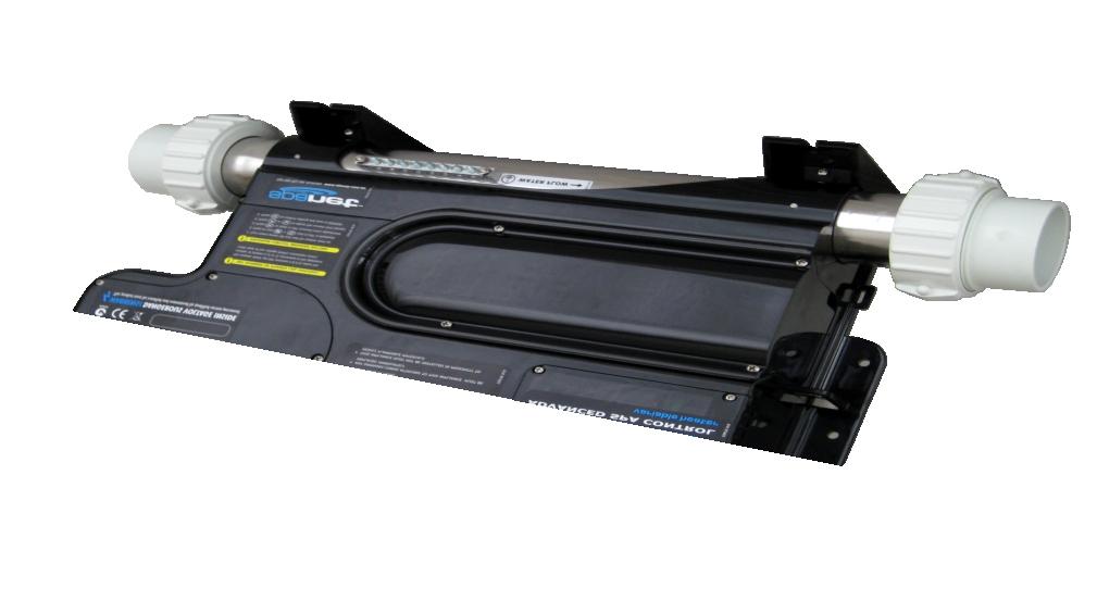
5 SV Series Overview Mains Power Terminal Block Heater Connection Terminal Block Fuse 1 (Phase 3 Loads) Fuse 2 (Phase 2 Loads) Fuse 3 (Phase 1 Loads) Low Voltage Connections (12V) keypads, lights, in-pool sensor digital/analog expand ports Mains Power Cable Entry Points Heartbeat LED DIP Switch Bank Wall Mount Bracket Wall Mount Bracket P Power Outlets ( V AC) for spa accessories: circ, o 3/uv, air blower jet pumps, auxiliaries TM Coupling (tail & nut) Coupling (tail & nut) Mounting Foot Earth Bonding Terminal Heater Tube Heater Cover Plate (remove to access heater connections) 3

6 TM Spa Pack Dimensions mm Front View mm 4 ADVANCED SPA CTROL variable heater Side View mm 6 mm mm Rear View mm mm mm Bottom View mm 6 mm mm mm mm mm 4

7 Keypad Dimensions mm SV2.T keypad 2.75" (70mm) LCD Screen 9 Keys Blue LED Backlighting mm 165mm x 94mm x 33.50mm 2.5m lead length SV-2T mm 6.00 mm mm mm mm R 37mm mm 5

8 Keypad Dimensions mm SV3.T / SV4.T keypad 3.5" (90mm) LCD screen 12 keys mm RGB colour mixing LED backlighting 185mm x 100mm x 33.50mm SV-3T 2.5m lead length mm 6.00 mm mm mm mm R 37mm mm 6
 x screws of appropriate length backed with flat washers.")
9 TM Spa Pack Installation Floor mounting procedure 4 ADVANCED SPA CTROL variable heater Due to its flexible design the spa pack can be installed on either the suction side or the discharge side of the filtration pump. Select a suitable location on the spa base and firmly secure spa pack to base using four (4) x screws of appropriate length backed with flat washers. Each screw should be positioned in the moulded cut outs of the mounting feet (refer above & aside). The spa pack should be fixed using ALL four screw locations to provide adequate support (two screws on each side of the spa pack). IMPORTANT NOTE The spa pack is NOT intended to be used outdoor. The spa pack must be installed in indoor environments only and should be installed in an enclosure so that all electrical connections cannot be accessible without the use of a tool (ie. under spa cabinet). NOTES Only use pan, round or truss head screws with flat washers DO NOT use countersunk screws. They may damage or crack the moulded mounting brackets The spa pack must be installed with the heater tube horizontal and should be positioned as low as possible in the pipe work of the spa. The spa pack can be plumbed for water flow in either direction however the most preferred direction is for water to flow from left to right. When constructing a spa care should be taken to minimise vibration from the pumps transferring to the spa pack through the base, frame or pipe work. Extended periods of vibration may lead to early component failure. The spa pack should be located at least 10cm (4") above potential flood level. If spa floor is on ground level the spa pack should be raised 10cm (4") above spa floor level. Install spa pack in a suitable position to prevent water dripping onto the unit. In particular avoid installing spa pack directly underneath keypad mounting location. 7
 x (2x4) treated timber beams or other suitable timber or metal materials to construct an adequate support structure to mount the spa pack to.")
 x screw hole locations provided on the moulded mounting brackets (refer aside) Only use pan, round or")
10 TM Spa Pack Installation Wall mounting procedure Due to its flexible design the spa pack can be installed on either the suction side or the discharge side of the filtration pump. Select a suitable location under the spa and use two (2) x (2x4) treated timber beams or other suitable timber or metal materials to construct an adequate support structure to mount the spa pack to. The mounting support frame should be capable of supporting the weight of the spa pack and should withstand the force of the pipe work moving each time the filtration pump starts or stops. 4 ADVANCED SPA CTROL variable heater Firmly secure spa pack to support frame using ALL four (4) x screw hole locations provided on the moulded mounting brackets (refer aside) Only use pan, round or truss head screws / bolts backed with flat washers DO NOT use countersunk screws or bolts. They may damage or crack the moulded mounting brackets NOTES The spa pack must be installed with the heater tube horizontal and should be positioned as low as possible in the pipe work of the spa. The spa pack can be plumbed for water flow in either direction however the most preferred direction is for water to flow from left to right. When constructing a spa measures should be taken to minimise vibration from the pumps transferring to the spa pack through the base, frame or pipe work. Extended periods of vibration may lead to early component failure. IMPORTANT NOTE The spa pack is NOT intended to be used outdoor. The spa pack must be installed in indoor environments only and should be installed in an enclosure so that all electrical connections cannot be accessible without the use of a tool (ie. under spa cabinet). The spa pack should be located at least 10cm (4") above potential flood level. If spa floor is on ground level the spa pack should be raised 10cm (4") above spa floor level. Install spa pack in a suitable position to prevent water dripping onto the unit. In particular avoid installing spa pack directly underneath keypad mounting location. 8
11 Keypad Installation All Models (SV2.T / SV3.T / SV4.T) Centre to Centre mm SV2.T Select a suitable keypad location that is above maximum water level and that is easily accessible to the spa user. Before drilling the cut out for the keypad, hold the keypad in place and check there is sufficient cable length to reach the spa pack without the cable being stretched or pulled against sharp edges. Drill two 76mm diameter holes spaced 71mm apart from centre to centre (as illustrated aside). Cut out the residual material between the two holes (as illustrated). Clean mounting surface to be free of dirt and dust particles, oil and grease. To ensure the keypad adhesive bonds to the spa well the shell must have a clean, smooth and dry surface. Peel paper backing from adhesive gasket ensuring all of the adhesive is exposed. 76 mm 76 mm Feed cable through opening, align keypad and press firmly onto mounting surface. Ensure keypad is adhered well to surface by pressing evenly around the outside edge of the whole keypad. IMPORTANT NOTES SV3.T / SV4.T The keypad mounting location should have adequate drainage to prevent accumulation of water on or around the keypad area. If keypad is to be mounted under a spa cover allow sufficient clearance to prevent cover resting directly on keypad. Parts incorporating electrical components (ie. keypads) must be fixed so that they cannot fall into the bath or spa KEYPAD CABLE CNECTI 76 mm Unscrew and remove low voltage connections cover from spa pack enclosure Connect keypad RJ45 plug into either TPAD1 or TPAD2 socket 147 mm Drip Loop Route the keypad cable through the cable guide provided Ensure the keypad cable has a drip loop before it enters the enclosure 9
12 SVT Keypad Cut Out Template SV2.T / SV3.T / SV4.T (Scale 1:1) NOTE: To print in 1:1 scale, set Page Scaling to NE in the print dialog box Centre to Centre mm 1 Drill both holes 2 with 76mm Hole Saw After drilling both holes remove this material from both sides 76 mm 76 mm 10
13 Electrical Wiring (Terminal Block Connections) AUS / NZ / European Models ( V AC) Tools Required: Wire Strippers, Phillips head screwdriver, flat head screwdriver Remove five (5) x Phillips screws from mains lid to access terminal block. Cut away appropriate length of outer insulation from mains power cable and strip away 25mm (1") of wire insulation from the end of each wire. Route mains cable through one of the two snap out holes provided and secure the cable with a gland to provide adequate cable strain relief (Tighten gland with use of a tool to ensure supply line anchorage point cannot be removed by hand).. Push the wires into the correct terminals as labelled. Refer wiring guide below or on the sticker inside the terminal block area. Tighten all screws on the terminal block with a screwdriver and check to ensure each wire has been firmly secured. Then screw mains lid back on. WARNING This appliance must be supplied through a residual current device (RCD) having a rated residual operating current not exceeding 30mA. Correct wiring of the main electricity board, RCD and spa pack is critical. When installing appliance refer to your local wiring regulations. When installing mains power cable providing service loops (additional wire length for future serviceability) to incoming wiring is recommended. P3 P2 CS P1 G N P3 P2 CS P1 G N P3 P2 CS P1 G N V (3 wire) single phase V (4 wire) dual phase V (5 wire) three phase Terminal Wiring Terminal Wiring Terminal Wiring P3 P2 CS P1 G N Link to CS Link to CS Link to P3 and P2 Phase Earth Neutral P3 Link to CS P2 Phase 2 CS Link to P3 P1 Phase 1 G Earth N Neutral P3 Phase 3 P2 Phase 2 CS Not used P1 Phase 1 G Earth N Neutral *Dip Switch 5 *Dip Switch 6 *Dip Switch 5 *Dip Switch 6 *Dip Switch 5 *Dip Switch 6 * Refer Dip switch information on page 11 11
14 DIP Switch Settings System Configuration Basic spa configuration is achieved by setting dip switches. The dip switches determine pump configuration and select the number of input phases wired to the spa pack. The installer must correctly configure the dip switches to match the pump and power configuration connected to the spa pack. The dip switch bank (illustrated aside) has six individual switches. Switches set to the top of the switch bank are in the position. Switches set to the bottom of the switch bank (closest to the numbers) are in the position. Refer to tables below for dip switch settings: SW Setting Notes SV2 / SV4 Models 1 Circ Fitted Not Fitted Fitted 2 Pump 1 Type Single Speed Two Speed If set to pump2 assumed fitted 3 Pump 3 Type Single Speed Two Speed Not used on SV2/SV2-VH models 4 Pump 4 Fitted Not Fitted Fitted Not used on SV2/SV2-VH models 5 Phase Selection Single Phase 2/3 Phase If set to dip switch 6 is enabled 6 Multi Phase Two Phase Three Phase SW Setting Notes SV3 Models Heartbeat LED 1 Circ Fitted Not Fitted Fitted 2 Pump 1 Type Single Speed Two Speed If set to pump2 assumed fitted 3 Pump 3 Fitted Not Fitted Fitted 4 Not Used Phase Selection Single Phase 2/3 Phase If set to dip switch 6 is enabled 6 Multi Phase Two Phase Three Phase Heartbeat LED Dip Switch Bank All SV model spa packs feature a heartbeat LED. The heartbeat LED flashes to indicate the current health/status of the spa pack. When the spa pack is functioning correctly with no errors to report the heartbeat LED emits a single flash in a constant pulse much like a heartbeat (,,, ). If the spa pack encounters a fault the heartbeat LED will begin flashing in sequence with the error code number being experienced (ie. ER2 =,;,; ). The heartbeat LED is located beside the bottom left hand corner of the dip switch bank and will emit its red flash through the tinted low voltage connection cover, making it clearly visible from the front of the spa pack. 12
15 Pump Configurations System Configuration Reference Table notes n/a = not available If pump1 = 2 spd, the pump 2 outlet socket cannot be used If pump3 = 2 spd, the pump 4 outlet socket cannot be used 13

.")

 pump 2 pump 4 blower mains* mains*")

.")
16 P Power Outlets V AC Output Multiple power output sockets are provided to run spa accessories. Each output socket is clearly labelled including the maximum current for that outlet. In addition the maximum current per phase is labelled. When connecting accessories the installer must consider the current draw of each appliance to be connected and ensure the system does not exceed the maximum load limits. The output sockets are wired with three sockets per phase (refer table below). The only exception is phase 1 which also powers the heater element (a socket is not provided, the heater is wired internally). Each phase circuit is protected by a fuse. P Power Outlets The sum total current draw of all appliances connected to a phase should not exceed the maximum current limit of that respective phase. Refer to ratings information labels on spa pack for current limits. In single phase applications the outlet sockets are still governed by the fuse/current limit of each phase. The power outlet arrangement is as follows: PHASE 1 PHASE 2 PHASE 3 Securing Lugs Locking Tabs circulation pump pump 1 pump 3 sanitiser (ozone/uv) pump 2 pump 4 blower mains* mains* heater# Plug Overmould * Dedicated V power outlets (always on) # Heater is connected internally to phase 1. Consider when calculating total current draw of phase 1 P Sockets & Plugs SV series spa packs utilise P mate-n-lok power connectors. The P connectors feature a key pattern for fail safe one way connection. When connecting accessory devices be sure to push cordset firmly into socket and ensure both side locking taps have been secured and latched in place (refer illustrations aside). P Outlets Cover Firmly secured and latched in place P Outlets Cover 12 For installations where there is insufficient depth under the spa skirt for the cable radius of an over moulded plug the installer can opt to fit the amp outlet cover and use non over moulded plugs to achieve a tighter cable radius. If accessories are connected with non over moulded P plugs the P outlet cover MUST be installed and fixed with screws. to The P outlet cover features snap out sections to be cut away at point of install to suit quantity of cords in use. 14


17 Low Voltage Connections 12V AC The low voltage connections are located on the top right hand corner of the spa pack. RJ45/RJ12 sockets are used for connection and are located inside the spa pack enclosure. The low voltage connections cover must be fitted and secured with screws for water proofing seal to work. Low Voltage Connections Cable guide holes used to route cables and form water proof seal The SV controllers feature the following low voltage connections: Socket Accessory TPAD1 Keypad #1 TPAD2* Keypad #2 IPTS In pool temperature sensor EXPAND1 Digital expansion port EXPAND2 Analogue expansion port LIGHT1 LED Light Output LIGHT2* LED Light Output * Sockets not available on SV2/SV2-VH models Drip Loop IMPORTANT NOTES 1A maximum 12V current draw. This is split between keypads, expand ports and lights. Each socket is rated to 1A maximum so the full 1A can be drawn from a single socket if required. Ensure each low voltage cable is routed through the cable guide hole on the side of the spa pack and allow for drip loops before entry to the enclosure. Port current sensing in pool temperature sensor The SV series spa packs monitor the RMS current drawn from the low voltage ports at all times. 12V current drawn by keypads, in pool temp sensors, expand ports and lights are measured. If the current is above 1.1A the controller will shut down and latch fault code (Er6-12V overload). Digital expand port A PC communications and general purpose digital interface port. Most suited to interfacing to other digital equipment such as stereos, remote controls etc Analog expand port colour LED spa light An analog expansion port that contains two analog inputs and a digital I2C bus. The I2C bus is shared with touch pad 1 port and allows connection of NXP I2C family of devices. 15
18 Heat Pump Installation How to connect a heat pump to a SVx-VH controller All variable heater models of the SV Series spa controllers have the capability to seamlessly integrate and control a heat pump for efficient heating and cooling of the spa water. Not all heat pumps can be connected to an SV controller. Only a SpaNET approved heat pump fitted with a SpaNET heat pump expansion module can be used. If connected the SV controller will automatically detect the heat pump and take control of its operation. All heat pump functions including heating / cooling / temperature adjustment / defrost cycles / over temp protection / diagnostics and monitoring are all controlled by the SV spa controller and the SV spa side touch pad. IMPORTANT NOTES Not all heat pumps can be connected to an SV controller. Only a SpaNET approved heat pump fitted with a SpaNET heat pump expansion module can be used. If the ambient temperature is below the operational limit of the heat pump (-10 'C) the SV heater element will be enabled regardless of the H.ELE setting, and the heat pump is disabled. HEAT PUMP CNECTI Connect power to the heat pump from either: a) a dedicated 230V mains outlet on the SV controller itself Note: Check ratings information of heat pump to be connected and ensure maximum current limit for the SV mains outlet is not exceeded b) a suitably rated and protected power supply The heat pump should be plumbed in-line before the SV controller so that water flows from the heat pump through the SV controller and then returns into the spa pool. If H.ELE is set to the SV heater element will operate in conjunction with the heat pump to boost heating only if the water temperature is 2'C or more below the set temperature point or the heat pump has been operating for more than 1 hour and the set temperature point has not been reached. A defrost cycle will run for a minimum of 3 minutes and a maximum of 10 minutes If the heat pump being used is fitted with a flow switch, the flow switch must close within 30 seconds of filtration pump operation otherwise a flow error will occur The heat pump MUST be installed according to the air space requirements detailed in the SV Series Heat Pump Installation Manual. Failure to do so will void heat pump warranty. Connect the heat pump data cable into the Expand2 (EXP2) data socket of the SV controller Finally configure the H.P (heat pump operating mode) and H.ELE (SV element boost) SETUP menu options to your desired specification (refer Setup menu section of SV Series User Manual) 16
19 Program Circuit Breaker Rating For variable element operation Press & hold + Current sensing Each VH (variable heater) model of SV controller contains mains current measurement hardware that allows the controller to monitor the RMS current draw. The current sensing hardware is only installed on Phase 1. Phases 2 and 3 can also be monitored if they are wired to terminal CS of the mains terminal block (refer wiring information on page 10). MODE 31 A 10: SA SU MO TU WE TH FR MODE Press MODE MODE C.LMT MODE 10: SA SU MO TU WE TH FR to enter adjustment 32 A 10: SA SU MO TU WE TH FR MODE MODE 33 A 10: SA SU MO TU WE TH FR MODE Current measurement is used for variable element operation. The purpose is to automatically adjust heater power level to match the residual current available when accessory devices (ie pumps and/or blower) are operating. The aim is to maximise heating input whilst spa is in use, but still remain within the current limit of the controller. The OEM menu item C.LMT (current limit) should be set to match the rating of the circuit breaker that feeds the spa pool. In multi phase installations the C.LMT should be set to match the current limit of Phase 1. To take full advantage of the variable element and maximise heater power level when spa in manual use the circuit breaker rating must be programmed correctly. Press to confirm & save The SV controller will shut down and latch fault code (Er10 - over current) if the SV controller detects a mains current above 110% of C.LMT. The actual current draw of the spa controller can be viewed at anytime via the diagnostics menu or by using the SpaNET Link PC application. The default current limit (C.LMT) values for each model are as follows: IMPORTANT NOTES The installer must program the C.LMT (current limit) setting to match the rating of the circuit breaker that feeds the spa pool or for multiphase installs the rating of the current limit of Phase 1. The C.LMT (current limit) setting is stored in non volatile memory (EEPROM) so it is remembered when power is turned off. The C.LMT setting only needs to be programmed once. (Note: C.LMT value is NOT adjusted by EEPROM reset) If the C.LMT (current limit) setting is not matched to the circuit breaker rating correctly the spa owner may experience either tripping circuit breakers or Er10 Over Current latching errors. Model Default C.LMT SV2-VH 15 amp SV3-VH 32 amp SV4-VH 40 amp How to program the current limit (C.LMT) : Press and hold and buttons together until C.LMT is displayed Press button to enter current limit (C.LMT) adjustment Press or to adjust current limit to match circuit breaker rating Press button to confirm and save setting 17
20 SA SU MO TU WE TH FR OEM Configuration Menu Access via keypad The SV controllers feature a hidden OEM configuration menu which allows complete customisation of the spa controller. Menu item options are detailed in the list below. To enter menu press and hold and buttons until [C.LMT] is displayed Press or to navigate through menu item list Press to enter menu item adjustment Press & hold + Press or to adjust setting Press to confirm setting and exit menu MODE MODE EXIT 10: SA SU MO TU WE TH FR 31 A 10: SA SU MO TU WE TH FR MODE MODE Press Press IMPORTANT NOTES MODE MODE C.LMT MODE 10: SA SU MO TU WE TH FR to enter adjustment 32 A 10: SA SU MO TU WE TH FR to confirm & save MODE L.SHD MODE 10: The OEM menu item settings are stored in non volatile memory (EEPROM) and are remembered when power is turned off. No need to reprogram settings when power is restored. During an EEPROM reset all menu items will be restored to the factory default settings except C.LMT/V.MAX/1.LLM/2.LLM/3.LLM. A ten (10) second idle menu time out period exists. If a button press is not detected for 10 seconds the menu will time out and the screen will return to the default display mode. MODE MODE 33 A 10: SA SU MO TU WE TH FR MODE Menu Item Setting Notes C.LMT Current Limit (circuit breaker rating) 10 to 60A L.SHD Load Shed Count 1 to 7 SANI Sanitiser (o 3/uv) on with spa use on / off C.JET Circ pump on with jet pump operation on / off V.ELE Variable element on / off V.MAX Maximum variable element power 3A to 25A H.USE Heat pump operation when spa in use on / off 1.LLM Phase 1 load limit 1 to 5 2.LLM Phase 2 load limit 1 to 5 (item disappears if set to 1 phase) 3.LLM Phase 3 load limit 1 to 5 (item disappears if set to 1 or 2 phase) o o UNIT Temperature format C or F o o A.HYS Adaptive hysteresis limit 0 to 20 C, 0.2 C increments (0=disabled) S 24 Sanitiser (o 3/uv) on 24 hrs on / off C 24 Circ pump on 24 hrs on / off CAL Calibration menu C.ZER Mains current zero push OK button to zero reading C.ADJ Mains current reading adjust with up/down buttons V.ADJ Mains voltage reading adjust with up/down buttons H.B H.C EXIT SERT Heat pump ambient temp reading Heat pump condenser temp reading Exit calibration submenu Service timers menu 1.SER Service timer 1 [service filters] 0 to 52 wks (0 wks = disabled) 2.SER Service timer 2 [service 1] 0 to 52 wks (0 wks = disabled) 3.SER Service timer 3 [service 2] 0 to 52 wks (0 wks = disabled) EXIT Exit service timers submenu D.FST Heat pump defrost calibration menu DO NOT adjust without advice from SpaNET EPRM Reset EEPROM values to factory default All values reset except C.LMT / x.llm / V.MAX EXIT 18 Exit OEM configuration menu DO NOT adjust without advice from SpaNET DO NOT adjust without advice from SpaNET
21 OEM Configuration Menu Menu item details L.SHD Load Shed Count V.ELE Variable Element Operation This setting determines the load shed behaviour of the heating element or heat pump (if fitted). Load shedding is governed by the load shed count (1 to 7). Load shed count = number of loads required to be turned for the heater to load shed and turn. The filtration pump is not counted as a load, the blower and all other pumps are. Example: Load Shed Count = 2 When any two loads in addition to the filtration pump are turned the heater load sheds and turns. The L.SHD setting ranges from 1 to 7. 1 = maximum load shed (default) 7 = load shed disabled SANI Sanitiser (o 3/uv) Operation Determines how the sanitiser power outlet operates during manual spa use. The setting choices are: sanitiser with pool use sanitiser with pool use (default) Variable element operation allows the SV controller to automatically adjust the heater power level to match the residual current available when accessory devices (ie pumps and/or blower) are operating. The benefit of this feature is the element can automatically reduce its power level and remain on instead of load shedding and turning off when spa is in manual use and jet pumps have been activated. The setting choices are: variable element enabled (default) variable element disabled Note: If disabled the heating behaviour is the same as a standard element. Load shed settings may need to be configured to ensure the spa pack does not exceed its maximum current limit. V.MAX Maximum Variable Element Size If variable element operation is enabled the installer also has the ability to limit the maximum current the heating element draws (3A to 25A) via the V.MAX menu item. This enables the installer to reduce the heater current draw where available power is limited, without the need to replace the heater element or spa pack. It also allows for the heater to be returned to maximum current if more power became available. The V.MAX setting ranges from 3A to 25A Default setting = 23A C.JET Circ on with Jet Pump H.USE Heat Pump Operation (when spa pool is in use) Determines behaviour of circ pump when jet pump is turned on for manual spa use. The setting choices are: circ pump forced with jet pump use circ pump controlled automatically (default) This setting determines whether the heat pump will operate if spa pool is in use. The benefit being that some spa owners may not wish to hear the noise of the heat pump running whilst they are using the spa. The setting choices are: heat pump operation ENABLED whilst spa is in use (default) heat pump operation DISABLED whilst spa is in use 19
22 OEM Configuration Menu Menu item details C 24 Circ Pump (24 hours) x.llm Load Limit Settings (Phases 1/2/3) This setting allows the installer to select the maximum number of loads (1-5) allowed to run at the one time. Different load limits can be set for each phase. 1.LLM = Phase 1 Load Limit 2.LLM = Phase 2 Load Limit 3.LLM = Phase 3 Load Limit Example: 1.LLM = 2 This will allow 2 x accessories (pump(s) and/or blower) to run at the one time, but as soon as you try and turn the 3rd accessory on the button will not work until you turn one of the other accessories off first. Only 2 x loads will ever be allowed to run at the one time. UNIT Temperature Format Used to select desired temperature format A.HYS Adaptive Hysteresis (Dynamic Thermal Tuning) The SV controllers feature adaptive hysteresis for heat control to reduce demand heating cycling. Adaptive hysteresis control tunes the temperature sensing to that particular spa pool and environment. It is particularly advantageous when in heater temperature sensing is employed. The A.HYS menu item allows the installer to set the maximum range that the hysteresis can be adjusted. o The A.HYS setting ranges from 0 to 20 C A value of 0 disables adaptive hysteresis o Default = 20 C S 24 Sanitiser (24 hours) The setting allows the sanitiser power outlet to be powered 24 hours per day The setting choices are: o o C or F sanitiser power outlet always sanitiser power outlet automatically controlled (default) The setting enables the circ pump outlet to be powered 24 hours per day The setting choices are: CAL circ pump power outlet always circ pump power outlet automatically controlled (default) Calibration Submenu Every SV controller is calibrated for mains voltage and current measurement during production. However, should the SV controller readings not agree with a true RMS multi meter reading they can be adjusted. The CAL sub menu offers the following options: C.ZER Mains current zero push OK button to zero reading C.ADJ Mains current reading adjust with up/down buttons V.ADJ Mains voltage reading adjust with up/down buttons EXIT V.ADJ C.ADJ Exit calibration submenu Field adjustment of the voltage reading should follow the following procedure: 1) Measure the mains voltage using a true RMS multi meter. 2) Adjust the voltage reading using V.ADJ to match the multi meter. Field calibration of the current reading should follow the following procedure: 1) Stop any current draw by disconnecting any fixed 230V loads and switching off heating, pumps, blower etc 2) Zero the current reading using C.ZER. 3) Apply maximum pump loads and measure the current draw using a true RMS multi meter. 4) Adjust current reading using C.ADJ to match multi meter reading. The SV measures the mains current that flows from Phase 1 terminal to phase 1 loads (heater, blower, ozone, circ). Any other loads connected via the CS terminal are also measured. 20
23 OEM Configuration Menu Menu item details CAL Calibration Submenu (continued) x.ser Service Timers In spa configurations where a heat pump is installed the Calibration CAL sub menu will offer a further two options: H.B Heat pump ambient temp reading adjust with up/down buttons H.C Heat pump condenser temp reading adjust with up/down buttons H.B Field adjustment of the heat pump ambient temperature reading should follow the following procedure: 1) Measure the ambient temperature around the heat pump external ambient thermistor using a true RMS multi meter thermistor. 2) Adjust the temperature reading using H.B to match the multi meter reading. These settings are used to enable and adjust service timers. A value of 0 results in the timer being disabled. Maximum timer value is 52 weeks. Independent counters are stored in R and therefore reset to 0 at power up. Counters for each service timer are incremented everyday at 8am. When the counter is greater or equal to the service timer value x 7, the touch pad will beep and scroll a message twice every 60 seconds. 1.SER message = "SERVICE FILTERS" 2.SER message = "SERVICE 2" 3.SER message = "SERVICE 3" The particular counter is reset by pressing the OK button whilst the service message is scrolling. H.C NOTE: Field adjustment of the heat pump condenser temperature reading should follow the following procedure: 1) Remove the heat pump external cabinet to gain access to the area where the condenser thermistor is located. 2) Measure the temperature of the heat pump condenser at the point where the heat pump condenser thermistor is located using a true RMS multi meter thermistor. 2) Adjust the temperature reading using H.C to match the multi meter reading. All SV controllers and SV series heat pumps are shipped precalibrated. DO NOT adjust the H.B or H.C settings unless specifically directed to by SpaNET. The x.ser setting ranges from 0 to 52 weeks. Default Values: 1.SER [SERVICE FILTERS] = 2 weeks 2.SER [SERVICE 2] = 0 weeks (disabled) 3.SER [SERVICE 3] = 0 weeks (disabled) D.FST Heat Pump Defrost Calibration Submenu These settings allow adjustment of various heat pump defrost parameters. All settings are pre-configured by SpaNET during production and should NOT be adjusted unless specifically directed to by SpaNET. Incorrect calibration could cause the heat pump to malfunction in cold conditions and this may void your product warranty. DO NOT ADJUST. 21
24 OEM Configuration Menu Menu item details EPRM EEPROM Reset Use this feature to reset all OEM menu and User menu items back to their default values. All values will be reset to their default setting except: C.LMT / V.MAX / 1.LLM / 2.LLM / 3.LLM The above values are NOT reset because they will have been customised to suit the particular spa pool and its available power supply by the spa manufacturer or installing electrician. EXIT Exit OEM Menu 22
25 Diagnostics Menu Access via keypad The SV controllers feature a hidden diagnostics menu which allows the installer / spa user to view onboard diagnostics and historical details about the spa controller. Menu item options are detailed in the list below. I To enter menu press and hold and and buttons Press or to navigate through menu item list Press to view diagnostic information on the selected item MODE EXIT 10: SA SU MO TU WE TH FR MODE Press & hold + + I Press MODE IMPORTANT NOTE WARN MODE 10: SA SU MO TU WE TH FR A ten (10) second idle menu time out period exists. If a button press is not detected for 10 seconds the menu will time out and the screen will return to the default temperature display mode. to view diagnostic information MODE S.DAT MODE 10: SA SU MO TU WE TH FR Menu Item Setting Notes WARN Warnings scroll IPTS presence, W8, mode, Vmax/Vmin S.DAT State date scroll Date displayed in DD - MM - YY S.VER TYPE PUMP Software version scroll Controller type scroll Pump selection scroll LIMS Limits scroll Refer table below for further Limits details IPTS Current IPTS reading If IPTS not fitted, display will show 9997 H.TMP C.TMP PS VOLT Current heater temperature reading Current case temperature Current mains current draw Current mains voltage V.ELE Current variable element power level 0 to 100% H.B H.C EXIT Heat pump ambient temperature Heat pump condensor temperature Exit menu The limits scroll provides a scrolling list of all current, phase and load limit settings as programmed in the OEM menu or set by dip switches. This feature is a quick way to verify controller settings. The list of items that will be displayed are: C.LMT Current limit setting (10 to 60A) L.SHD Load shed count (1 to 7) PHSE Phase configuration (1,2 or 3 phase) 1.LLM Phase 1 load limit (1 to 5) 2.LLM Phase 2 load limit (1 to 5) 3.LLM Phase 3 load limit (1 to 5) P.HYS H.HYS Current pool temperature sensor adaptive hysteresis value (0-200; where 1 = 0.1'C) Current heater temperature sensor adaptive hysteresis value (0-200; where 1 = 0.1'C) 23
26 Contact Us Spa Net Pty Ltd Unit Railway Road North Mulgrave NSW 2756 Australia Phone: Fax: service@spanet.com.au accounts@spanet.com.au sales@spanet.com.au Technical Support & Service Accounts Department Sales Department 24
Contents. Specifications. Description SV HP 55 SV HP 90. Specifications Warnings Introduction Overview... 4
 Contents Specifications Specifications... 1 Warnings... 2 Introduction... 3 Overview... 4 Installation Instructions... 5 Cable Connections... 6 Plumbing Diagram... 7 Electrical Wiring Diagram... 8 SV System
Table of Contents. V.1704 Page 2
 Table of Contents WARNINGS... 3 ELECTRICAL INSTALLATION... 4 Wiring Diagram (Mini 1)... 4 Wiring Diagram (Mini 2)... 5 DIP SWITCHES... 5 TOPSIDE PANELS... 6 SV Mini 1 Layout... 6 SV Mini 2 Layout... 6
SV SERIES USER MANUAL
 SV SERIES USER MANUAL TABLE OF CONTENTS SYSTEM OPERATING MANUAL Time/Date and Water Chemistry Warning... 3 SV Series Features Overview.. 4 SV2.T Overview... 5 SV3.T Overview... 6 SV4.T Overview... 7 Water
DRAFT INSTALLATION INSTRUCTIONS. Solid-State Series !! NOTE!! Covers the following models: Refer to INSERT for additional information
 INSTALLATION INSTRUCTIONS Solid-State Series!! NOTE!! Covers the following models: " CS6100 - CS7100 " CS6200 - CS9200 " CS6220 - CS9220 " CS6230 - CS9230 " CS6500 - CS7500 " CS6330 - CS9300 " CS9400 -
Spa Touch Control Panel with BP2100, BP6013 spa controllers. (Spa Owner s Manual insert)
") Spa Touch Control Panel with BP2100, BP6013 spa controllers. (Spa Owner s Manual insert) P.N. 7876C (export) February 12, 2015 For Spas equipped with BP2100, BP6013 controllers and Spa Touch panel. Spa
Spa Touch Control Panel with BP2100, BP6013 spa controllers. (Spa Owner s Manual insert) P.N. 7876C (export) February 12, 2015 For Spas equipped with BP2100, BP6013 controllers and Spa Touch panel. Spa
Instruction Manual Machine P/N: # & #
 Instruction Manual Machine P/N: 1000830# & 1000831# 1 CONTENTS 1. INFORMATION...3 1. Introduction...3 2. Safety...3 3. Warning Notes...3 4. Contact...4 5. Electrical Installation Procedure...4 6. Plumbing
Spa Touch Control Panel with 2000, 2100 controllers. (Spa Owner s Manual insert)
") Spa Touch Control Panel with 2000, 2100 controllers (Spa Owner s Manual insert) P.N. 7876B February 11, 2015 For Spas equipped with BP2000, BP2100 controllers and Spa Touch panel. Spa Touch Control Panel
Spa Touch Control Panel with 2000, 2100 controllers (Spa Owner s Manual insert) P.N. 7876B February 11, 2015 For Spas equipped with BP2000, BP2100 controllers and Spa Touch panel. Spa Touch Control Panel
Table of Contents. V.1802 Page 2
 Table of Contents SAFETY WARNINGS FOR SPA PACK... 3 INTRODUCTION... 4 TOUCH PANEL LAYOUT... 4 Status Indicators... 5 Current Activity Scroll... 5 Light Sensor / Automatic Brightness... 5 Auto-Dim Screen...
PORTAPAC / DELTA HOT. Installation and Operation Manual. ! WARNING
 PORTAPAC / DELTA HOT Installation and Operation Manual! WARNING This equipment must be installed and serviced by a qualified technician. Improper installation can create electrical hazards which could
MIX Boiler & Font Range Service Manual
 MIX Boiler & Font Range Service Manual 1000870# 1000871# 1000875# 1000880# 1000887# 1000878 1000879 2300268 www.marcobeveragesystems.com Ireland Tel: +353 (1) 295 2674 UK Tel: +44 (0207) 2744577 Service
CONTENTS CONSIDERATIONS. General Plumbing Component Connection ILLUSTRATION. Control System CONFIGURATION. Voltage Verification CONNECTION
 AIR SERIES SYSTEM INSTALLATION MANUAL CONTENTS CONSIDERATIONS General Plumbing Component Connection 2 2 2 ILLUSTRATION Control System 3 CONFIGURATION Voltage Verification 4 CONNECTION Component Connection
INSTRUCTION MANUAL. Blue Whale Spa Ltd, 11 Glaisdale Drive East Nottingham, NG8 4GU
 INSTRUCTION MANUAL Balboa 500Z-Series Operation Guide Initial Start-up Your spa will enter Priming Mode ( ) when it is energized. During Priming Mode, press Jets button(s) repeatedly and be sure all pumps
Refrigeration Controller Operator s Manual (HRC) PO Box 6183 Kennewick, WA
 PO Box 6183 Kennewick, WA") Refrigeration Controller Operator s Manual (HRC) PO Box 6183 Kennewick, WA 99336 www.jmcvr.com 1-509-586-9893 Table of Contents TABLE OF FIGURES...1 OVERVIEW OF THE HRC CAPABILITIES...2 INSTALLATION AND
Refrigeration Controller Operator s Manual (HRC) PO Box 6183 Kennewick, WA 99336 www.jmcvr.com 1-509-586-9893 Table of Contents TABLE OF FIGURES...1 OVERVIEW OF THE HRC CAPABILITIES...2 INSTALLATION AND
OPERATING & MAINTENANCE MANUAL HORIZONTAL WATER SOURCE HEAT PUMP. World class comfort.
 OPERATING & MAINTENANCE MANUAL HORIZONTAL WATER SOURCE HEAT PUMP World class comfort. welcome Congratulations on your selection of Ice Air Water Source Heat Pumps (WSHPs) for your comfort conditioning
Table of contents. in.k200 keypad overview - introduction function description instructions Typical settings...
 table of contents Table of contents introduction... 3 warnings...4 features... 5 overview - overview...7 - dimensions...8 - in.k200 dimensions...9 installation - floor installation... 10 - wall installation...
READ AND FOLLOW ALL INSTRUCTIONS SAVE THESE INSTRUCTIONS
 READ AND FOLLOW ALL INSTRUCTIONS SAVE THESE INSTRUCTIONS 1 IMPORTANT SAFETY INSTRUCTIONS Read the instructions The appliance is not to be used by persons (including children) with reduced physical, sensory
SERVICE MANUAL. Ecoboiler Model range: T20 ( ) T30 ( )
 T30 ( )") SERVICE MANUAL Ecoboiler Model range: T20 (1000662) T30 (1000663) Marco Beverage Systems Ltd. 63d Heather Road, Sandyford Industrial Estate, Dublin 18, Republic of Ireland Ireland Tel: (01) 295 2674 Ireland
SERVICE MANUAL Ecoboiler Model range: T20 (1000662) T30 (1000663) Marco Beverage Systems Ltd. 63d Heather Road, Sandyford Industrial Estate, Dublin 18, Republic of Ireland Ireland Tel: (01) 295 2674 Ireland
Table of contents. in.k200 keypad overview - introduction function description instructions Typical settings...
 in.xe in.xe table of contents Table of contents introduction... 3 warnings...4 features... 5 in.xe overview - overview...7 - in.xe dimensions...8 - in.k200 dimensions...9 in.xe installation - floor installation...
SP800 & SP1200 Installation & Service Manual
 SP800 & SP1200 Installation & Service Manual SP800 (2.0kW & 3.0kW) SP1200 (3.5kW, 4.5kW & 6.0kW) The SP800 and SP1200, mid to high end range of spa pool control systems can be installed and configured
Installation Instructions. Filtered Chilled drinking water for commercial kitchens and tea rooms.
 Installation Instructions Zip HydroTap Filtered Chilled drinking water for commercial kitchens and tea rooms. Affix Model Number Label Here 801525 801525 - Zip HydroTap Installation Instructions - Nov.
Model 1820 Dehumidifier
 Model 1820 Dehumidifier Installation Instructions SAFETY INSTRUCTIONS WARNING 1. 120 Volts may cause serious injury from electric shock. Disconnect electrical power before starting installation or servicing.
Ecoboiler T20 & T30 SERVICE MANUAL. Marco Beverage Systems Ltd. 63d Heather Road, Sandyford Industrial Estate, Dublin 18, Republic of Ireland
 Ecoboiler T20 & T30 SERVICE MANUAL Marco Beverage Systems Ltd. 63d Heather Road, Sandyford Industrial Estate, Dublin 18, Republic of Ireland Ireland Tel: (01) 295 2674 Ireland Fax: (01) 295 3715 UK Tel:
Mix Boiler & Font Range ( #, #, #, , )
") Mix Boiler & Font Range (1000870#, 1000871#, 1000880#, 1000878, 1000879) Service Manual Marco Beverage Systems Ltd. 63d Heather Road, Sandyford Industrial Estate, Dublin 18, Republic of Ireland Ireland
Mix Boiler & Font Range (1000870#, 1000871#, 1000880#, 1000878, 1000879) Service Manual Marco Beverage Systems Ltd. 63d Heather Road, Sandyford Industrial Estate, Dublin 18, Republic of Ireland Ireland
Instruction FH-CWP Thermostat
 Instruction FH-CWP Thermostat Index Instruction FH-CWP Thermostat 1. Functional Overview.......................... 3 2. Mounting..................................... 4 3. Installation....................................
INSTRUCTION MANUAL. Blue Whale Spa Ltd, 11 Glaisdale Drive East Nottingham, NG8 4GU
 INSTRUCTION MANUAL MVP260 Control Reference Card Non-Circ Operation Initial Start-up When your spa is first actuated, it will go into Priming mode, indicated by Please see the M-7 Installation Instruction
AQUARIUS 45 MARINE SERVICE MANUAL
 AQUARIUS 45 MARINE SERVICE MANUAL CONTENTS: PAGE 1. INTRODUCTION 3 2. SAFETY INSTRUCTIONS 4 3. BASIC INSTRUCTIONS 5 3.1. Installation Details 5 3.2. Operating the Boiler for the First Time 6 3.3. Troubleshooting
INSTALLATION INSTRUCTIONS UNDERCOUNTER DISHWASHERS
 INSTALLATION INSTRUCTIONS UNDERCOUNTER DISHWASHERS VIKING 111 Front Street Greenwood, Mississippi 38930 USA (662) 455-1200 IMPORTANT - PLEASE READ AND FOLLOW Before beginning - please read these instructions
Convection Panel Heater
 Convection Panel Heater INSTRUCTION MANUAL MODEL: JCPH-2000 AFTER SALES SUPPORT (AU) 1300 886 649 (NZ) 0800 836 761 Contents Important Safety Instructions 3 Product Overview 6 Getting Started 8 Operating
Safety / Kit Components 1
 Installation & Operation Manual Industrial Wall Control IWC0 (incorporating SmartHub and Fault Indicating features) Safety / Kit Components SAFETY Please read this manual carefully. Your failure to do
Owner s Manual. Spa Blower ONGA. Installation & operation instructions
 Owner s Manual ONGA Spa Blower Installation & operation instructions Should the installer or owner be unfamiliar with the correct installation or operation of this type of equipment you should contact
INSTRUCTION MANUAL. Blue Whale Spa Ltd, 11 Glaisdale Drive East Nottingham, NG8 4GU
 INSTRUCTION MANUAL Balboa 500DZ-Series Operation Guide Initial Start-up Your spa will enter Priming Mode ( ) when it is energized. During Priming Mode, press Jets button(s) repeatedly and be sure all pumps
Carbon Monoxide Transmitter
 Introduction The CO Transmitter uses an electrochemical sensor to monitor the carbon monoxide level and outputs a field-selectable 4-20 ma or voltage signal. The voltage signal may also be set to 0-5 or
VADA - Rain2Main Automatic Rainwater Controller
 PRODUCT OVERVIEW / APPLICATION The Vada Rain2Main is designed to select between stored rainwater (when available) and mains supply water, and send this water to your toilet cistern, washing machine, garden
TechBook. in.xetm innovative spa pack platform. Versatile Easy to install Watertight
 TechBook in.xetm invative spa pack platform Versatile Easy to install Watertight Table of contents Warnings 2 Introduction 3 Features 4 Overview 5 in.xe dimensions: 5 In.k200 dimensions: 6 in.xe installation
Hand Dryer Installation & User Manual
 Hand Dryer Installation & User Manual Please read instructions in conjunction with the illustrations Please save these instructions. Safety & Guidance notes Important:- Read all these instructions before
BR342 Ducted Installation Instructions Australian Version Electronic Wall Control
 Australian Version Electronic Wall Control 1 Introduction The BR342 reverse cycle rooftop air-conditioner is designed for installation onto Recreational Vehicles (RV s) at the time of manufacture or as
Genus III Pool and Spa Controller
 Genus III Pool and Spa Controller INSTALLATION & OPERATING INSTRUCTIONS AstralPool Australia Pty. Limited. A.B.N. 97 007 284 504 Infmation and specifications subject to change without notice. Melbourne:
Zip Autoboil Installation and Operating Instructions
 Zip Autoboil Installation and Operating Instructions 315052 Zip Autoboil 15 Litre White 313051 Zip Autoboil 15 Litre Stainless Steel 325052 Zip Autoboil 25 Litre White 325051 Zip Autoboil 25 Litre Stainless
spatouch Menued Control Panels
 spatouch Menued Control Panels Balboa Water Group BP Series Systems User Interface and Programming Reference The spatouch menued panel is compatible with all BP systems that already support the TP800 and/or
Electronically controlled instantaneous water heater. CEX 9-U: C models. Installation instructions
 Electronically controlled instantaneous water heater CEX 9-U: 27910-50 C models Installation instructions For 50 ºC models, the appliance delivers water not exceeding 50 ºC in accordance with AS3498. 1.
1.1 Controller General Information
 1.1 Controller General Information The Aestiva S1000 controller is differential controller specifically designed for forced circulation solar system. It incorporates a microprocessor driven PCB board and
"WHHR125DC" Whole House Heat Recovery Unit with Low Energy DC Motor. Installation, Operating and Maintenance Instructions domestic and commercial use
 "WHHR125DC" Whole House Heat Recovery Unit with Low Energy DC Motor Installation, Operating and Maintenance Instructions domestic and commercial use Page 2 Contents Section Page Number Introduction 3 How
aura-t TP536/GBR ventilation systems
 EN aura-t TP536/GBR Product Manual HRV controller ventilation systems Warnings, Safety information and Guidance Important Information Read instructions fully before the installing this appliance. 1. This
HT-2 / 9600 Series Control Contents
 HT-2 / 9600 Series Control Contents Tools & Parts Tools Required Parts Required Error Messages 3 Flashing Dots Pressure or Flow Switch Not Activated Pressure or Flow Switch Activated Temperature Sensor
DIGIHEAT IN LINE HEATERS
 DIGIHEAT IN LINE HEATERS Installation and operation manual for Single & Three Phase Models Offices - Australia NSW - Sydney (Head Office) Tel: +61 2 9898 8600 QLD - Brisbane Tel: +61 7 3299 9900 VIC/TAS
INSTALLATION INSTRUCTIONS FOR 8330*5511 MOUNTING KIT
 RV Products Division INSTALLATION INSTRUCTIONS FOR 8330*5511 MOUNTING KIT 8330-752 CONTROL BOX KIT (12 VDC COOL ONLY) 9330A755 CONTROL BOX KIT (12 VDC HEAT/COOL) 8530-750 CONTROL BOX KIT (24 VAC COOL ONLY)
Owners Manual PORTAPAC
 Portapac Inst/ Operation Owners Manual - Dimension : 279mm(H) X 210mm(W) = A4 size Code No: (63813896) 10/ 2005 Date: 05/ 10/ 2005 Owners Manual Waterco Limited ABN 62 002 070 733 This equipment must be
V80-H Multistage Pump Instruction Manual
 V80-H Multistage Pump Instruction Manual PRODUCT OVERVIEW The VADA horizontal multistage centrifugal pumps combine the functional benefits of centrifugal pumps and the practical benefits of self priming
CLEARLY ADVANCED SPA SYSTEMS! OWNER'S MANUAL MC-MP-SBD SPA SYSTEMS INSTALLATION, INSTRUCTIONS & MORE! TAKING OVER THE WAVES!
 CLEARLY ADVANCED SPA SYSTEMS! OWNER'S MANUAL MC-MP-SBD SPA SYSTEMS INSTALLATION, INSTRUCTIONS & MORE! TAKING OVER THE WAVES! Contents Warning Important Warning Instructions 3 General Information Preliminary
C-Bus Four Channel General Input Unit Installation Instructions
 C-Bus Four Channel General Input Unit Installation Instructions 5504GI Series REGISTERED DESIGN REGISTERED PATENT Table of Contents Section...Page 1.0 Product Range... 3 2.0 Description... 3 3.0 Capabilities...
BP501G3 Tech Sheet. Part Number: Incoloy Incoloy Titanium. Custom Box Overlay Box Overlay Part Number N/A
 BP501G3 Tech Sheet Customer: Balboa Water Group Part Number: 56582 800 Incoloy 56583 825 Incoloy 56584 Titanium Custom Box Overlay Box Overlay Part Number N/A UL System Model: BP501-BP501G3-AU Software
INSTALLATION INSTRUCTIONS FOR MOUNTING KIT
 RV Products Division INSTALLATION INSTRUCTIONS FOR 8330-5501 MOUNTING KIT 8330-752 CONTROL BOX KIT (12 VDC COOL ONLY) 9330B755 CONTROL BOX KIT (12 VDC HEAT/COOL) 8530-750 CONTROL BOX KIT (24 VAC COOL ONLY)
MSPA-MP METAPACK SERVICE MANUAL. Visual step-by-step guide to easily identify & correct technical problems! Gecko Electronics Inc.
 MSPA-MP METAPACK SERVICE MANUAL Gecko Electronics Inc. Visual step-by-step guide to easily identify & correct technical problems! Table of Contents Power & Ground Check Tools and Parts 3 Electrical Wiring
INSTALLATION INSTRUCTIONS FOR 7370A736 FLUSH MOUNT CEILING PLENUM
 INSTALLATION INSTRUCTIONS FOR 7370A736 FLUSH MOUNT CEILING PLENUM TABLE OF CONTENTS Warnings...2 Package Contents...2 General Information...3 Ceiling Plenum Installation Requirement...3 Supply Ducting
Owner s Guide and. Gas Continuous Flow Water Heater 27L Gas Water Heater 874 & 872 Series, 627 Models
 Owner s Guide and Installation Instructions Gas Continuous Flow Water Heater 27L Gas Water Heater 874 & 872 Series, 627 Models This water heater must be installed and serviced by an authorised person.
Table of contents. in.k200 keypad overview - introduction function description instructions Typical settings...
 table of contents Table of contents introduction... 3 warnings...4 features... 5 overview - overview...7 - dimensions...8 - in.k200 dimensions...9 installation - floor installation... 10 - wall installation...
Spa Control System OWNER S MANUAL
 LIMITED WARRANTY ONE YEAR LIMITED WARRANTY: UNITED SPAS, INC. warrants, to the original purchaser, the Spa Equipment against defects in materials or workmanship for a period of one year from date of purchase.
Series DCT1000DC Dust Collector Timer Controller Specifications Installation and Operating Instructions
 Series DCT1000DC Dust Collector Timer Controller Specifications Installation and Operating Instructions Bulletin E-97DC Thank you for purchasing the Dwyer DCT1000DC Dust Collector Timer Controller. You
Dehumidifier User Manual. (For the series of DP40~DP70)
") Dehumidifier User Manual (For the series of DP40~DP70) Content I. Please read immediately... 1 II. Application... 2 III. Features... 2 IV. Technical Parameters... 3 V. Overall Dimension... 4 VI. Installation
Dehumidifier User Manual (For the series of DP40~DP70) Content I. Please read immediately... 1 II. Application... 2 III. Features... 2 IV. Technical Parameters... 3 V. Overall Dimension... 4 VI. Installation
UNDERCOUNTER SERVICE MANUAL. Ecoboiler UC4L 2.4kW Ecoboiler UC10L 2.8kW Ecoboiler UC10L 5.6kW Ecosmart UC4L 2.
 UNDERCOUNTER SERVICE MANUAL Ecoboiler UC4L 2.4kW 1000740 Ecoboiler UC10L 2.8kW 1000741 Ecoboiler UC10L 5.6kW 1000742 Ecosmart UC4L 2.4kW 1000750 Ecosmart UC10L 2.8kW 1000751 Ecosmart UC10L 5.6kW 1000752
Duct and Rough Service Carbon Monoxide Sensor
 Product Identification and Overview Duct and Rough Service Carbon Monoxide Sensor BAPI s Carbon Monoxide Sensor offers enhanced electrochemical sensing with outstanding accuracy at low concentrations.
INSTALLATION INSTRUCTIONS FOR MOUNTING KIT 7330B751 CONTROL BOX KIT (12 VDC COOL ONLY) CONTROL BOX KIT (12 VDC HEAT/COOL)
 CONTROL BOX KIT (12 VDC HEAT/COOL)") INSTALLATION INSTRUCTIONS FOR 8330-5511 MOUNTING KIT 7330B751 CONTROL BOX KIT (12 VDC COOL ONLY) 9330-755 CONTROL BOX KIT (12 VDC HEAT/COOL) 7530B750 CONTROL BOX KIT (24 VAC COOL ONLY) 9530-755 CONTROL
INSTALLATION INSTRUCTIONS FOR 8330-5511 MOUNTING KIT 7330B751 CONTROL BOX KIT (12 VDC COOL ONLY) 9330-755 CONTROL BOX KIT (12 VDC HEAT/COOL) 7530B750 CONTROL BOX KIT (24 VAC COOL ONLY) 9530-755 CONTROL
Marco Beverage Systems Ltd. INSTRUCTIONS FOR MODELS
 Marco Beverage Systems Ltd. INSTRUCTIONS FOR MODELS Ecoboiler UC4L 2.4kW (1000740#) Ecoboiler UC10L 2.8kW (1000741#) Ecoboiler UC10L 5.6kW (1000742#) Ecoboiler UC4L 1.5kW 110V (1000747) Ecosmart UC4L 2.4kW
IMPORTANT SAFETY INFORMATION:
 08/53542/0 (AU/NZ) Issue 1 Owner s Manual Model BLF5051-AU/ PRISM 50" EN IMPORTANT SAFETY INFORMATION: Always read this manual first before attempting to install or use this fireplace. For your safety,
WAILEA OWNER S MANUAL
 WAILEA OWNER S MANUAL The blades in each pack are matched for equal weight to assure smooth fan operation. If more than one fan is being installed, be careful not to mix blades from different cartons.
Congratulations! You've just purchased a new Marey ECO tankless water heater and will soon begin to enjoy the benefits of going tankless.
 Congratulations! You've just purchased a new Marey ECO tankless water heater and will soon begin to enjoy the benefits of going tankless. Please take the time to thoroughly read and understand this safety
ECONO FLO VSA 165 VARIABLE SPEED PUMP OWNER S MANUAL
 ECONO FLO VSA 165 VARIABLE SPEED PUMP OWNER S MANUAL IMPORTANT SAFETY INSTRUCTIONS READ AND FOLLOW ALL INSTRUCTIONS SAVE THESE INSTRUCTIONS WARNING: Before installing this product, read and follow all
Inspect bath carefully and report any damage or faults before installation. No claims can be entered in to after installation.
 V4, 1, 2012 A3\4 Installation Instructions Inspect bath carefully and report any damage or faults before installation. No claims can be entered in to after installation. Protect the bath throughout installation
OVEN INDUSTRIES, INC.
 OVEN INDUSTRIES, INC. OPERATING MANUAL Model 5C7-252 TEMPERATURE CONTROLLER With PLC Inputs Introduction Thank you for purchasing our controller. The Model 5C7-252 is an exceptionally versatile unit and
UB1 AIR CONDITIONING UNIT INSTALLATION INSTRUCTIONS
 UB1 AIR CONDITIONING UNIT INSTALLATION INSTRUCTIONS INSTALLATION INSTRUCTIONS: Carefully read these instructions before installing your new air-conditioner. AUSTRALIAN AUTOMOTIVE AIR AL00500054E 1 Table
NON-SUBMERSIBLE WATER PUMP
 NON-SUBMERSIBLE WATER PUMP MODEL NO: CEB103 PART NO: 7230327 OPERATION & MAINTENANCE INSTRUCTIONS LS0114 INTRODUCTION Thank you for purchasing this CLARKE Water Pump, which is a general purpose pump, suitable
Programmable Thermostat
 Set & $ave Programmable Thermostat Installation and Operation Manual English Model 44360 Form# 42710-01 20091204 2009 Hunter Fan Co. 2 Table of Contents Important Information... 5 Tools... 6 Uninstalling
INSTALLATION GUIDE NZ AU
 DISHWASHER DW60U6I & DW60U2I models INSTALLATION GUIDE NZ AU 1 SAFETY AND WARNINGS 100 lb 45 kg! WARNING! Electrical shock hazard Before installing the dishwasher, remove the house fuse or open the circuit
hc9620 Ceramic Hob Manual for Installation, Use and Maintenance
 hc9620 Ceramic Hob Manual for Installation, Use and Maintenance Customer Care Department The Group Ltd. Harby Road Langar Nottinghamshire NG13 9HY T : 01949 862 012 F : 01949 862 003 E : customer.care@cda.eu
SMF PUMP OWNER S MANUAL
 SMF PUMP OWNER S MANUAL IMPORTANT SAFETY INSTRUCTIONS READ AND FOLLOW ALL INSTRUCTIONS SAVE THESE INSTRUCTIONS WARNING: Before installing this product, read and follow all warning notices and instructions
GEM-C Wireless User & Installation Manual. Revision October Apollo Solar Electric Limited. Documentation
 Documentation GEM-C Wireless User & Installation Manual Revision October 2014 Apollo Solar Electric Limited Contents GEM-C Wireless User Manual 3 Important Safety Information 3 Introduction 4 The GEM-C
Analog Room Pressure Monitor RPC Series
 Description The Room Pressure Monitor is used to measure differential pressure in the range of 0.125 to 1"wc or 30 to 250 Pa. It combines precision high sensitivity silicon sensing capabilities and the
AIR CONDITIONER OPERATING MANUAL. Duct type. Indoor Unit ARTG45LDTA ARTG54LDTA ARTG60LDTA KEEP THIS MANUAL FOR FUTURE REFERENCE. PART No.
 AIR CONDITIONER OPERATING MANUAL Duct type Indoor Unit ARTG45LDTA ARTG54LDTA ARTG60LDTA KEEP THIS MANUAL FOR FUTURE REFERENCE PART No. 98067 98067_OM_EN.indd 07-Aug-5 :40:5 OPERATING MANUAL PART No. 98067
SCHWAN INSTALLATION GUIDE
 SCHWAN INSTALLATION GUIDE For Schwan Versatap SC52E Instant Hot Cold Filtered Water FOR SERVICE OR ASSISTANCE CALL MERQUIP ON 0800 636 0 636. Schwan recommends that a qualified tradesperson installs your
Sundance Spas SPA EQUIPMENT SYSTEM. Installation Instructions. P/N Rev. A
 Sundance Spas SPA EQUIPMENT SYSTEM Installation Instructions P/N 6530-456 Rev. A Contents Important Notices 1 Important Safety Instructions 2 Where to Place the Equipment System 3 Connecting Pipes Between
Installation and operating instructions. Temperature difference controller 6 inputs, 3 outputs, integrated data logger for SD card
 SOLARTHERMIE - SOLAR THERMAL - SOLAR TÉRMICO - SOLAIRE THERMIQUE - SOLARE TERMICO Installation and operating instructions Temperature difference controller 6 inputs, 3 outputs, integrated data logger for
FIRERAY 5000 range USER GUIDE
 FIRERAY 5000 range USER GUIDE 0044-003-04 IMPORTANT PLEASE NOTE: The beam path MUST be kept clear of obstructions at all times! Failure to comply may result in the Detector initiating a Fire or Fault signal.
air pump 2700/4500 ? 2YEAR GUARANTEE UK AIRPUMP _33435 CASC /10/ :16 Page 1
 33719-000 UK AIRPUMP 2700-4500_33435 CASC.450 13/10/2011 09:16 Page 1 2823 1820 1380 air pump 2700/4500 Hozelock Ltd. Midpoint Park, Birmingham B76 1AB. England Tel: +44 (0) 121 313 1122 info@hozelock.com
TH146-P-2H1C. 1. Introduction. 2. Installation. 1.1 Applications. 2.1 Control Module (CT280-2H1C) 1.2 Supplied Parts. 1.
 1.2 Supplied Parts. 1.") TH146-P-2H1C Installation Guide Programmable 2H1C Controller Removable Connector * Removable Connector * TH146-P User Console CT280-2H1C Control Module AC144-03 Outdoor Temperature Sensor * To remove a
TH146-P-2H1C Installation Guide Programmable 2H1C Controller Removable Connector * Removable Connector * TH146-P User Console CT280-2H1C Control Module AC144-03 Outdoor Temperature Sensor * To remove a
Marco Beverage Systems Ltd.
 Marco Beverage Systems Ltd. INSTRUCTIONS FOR MODELS ECOSMART PB10, ECOSMART PB10 Hi Deck ECOSMART T10 (P/N: 1000677#, 1000678#, 1000674#) Water pressure : 5-50 psi (min.-max.)35-345 kpa (min.-max.) Marco
Installation & Service Manual. Models ALF 20, 30, 40, 50, 60, 80
 Installation & Service Manual Models ALF 20, 30, 40, 50, 60, 80 IMPORTANT! Read all safety instructions before installing, using, or servicing the heater. Installation & servicing should only be carried
Xcelsior Spa Pool System
 Davey Repair or Replacement Guarantee In the unlikely event in Australia or New Zealand that this Davey product develops any malfunction within two years of the date of original purchase due to faulty
Emerson Inspire 1HDEZ Installation Instructions. Thermostat/Interface Equipment Control TROUBLESHOOTING
 Emerson Inspire 1HDEZ-1521 Installation Instructions Thermostat/Interface Equipment Control TROUBLESHOOTING FAILURE TO READ AND FOLLOW ALL INSTRUCTIONS CAREFULLY BEFORE INSTALLING OR OPERATING THIS CONTROL
OPERATING MANUAL Enertronic Control System 2
 OPERATING MANUAL Enertronic Control System 2 The integrated control system for Lennox chillers in the Ecologic range Manufacturer: Lennox Benelux B.V. Postbus 1028, 3860 BA NIJKERK Watergoorweg 87, 3861
aura-t TP536/EU ventilation systems
 EN aura-t TP536/EU Product Manual HRV controller ventilation systems Warnings, Safety information and Guidance Important Information Read instructions fully before the installing this appliance. 1. This
INSTALLATION INSTRUCTIONS
 INSTALLATION INSTRUCTIONS TM DishDrawer dishwasher DD4S 7 & DD4ST 7 models US CA 59004D 04.3 FOLLOW THE INSTALLATION SEQUENCE RELEVANT TO YOUR MODEL STANDARD HEIGHT SINGLE MODELS TALL HEIGHT SINGLE MODELS
R32. Installation Manual Split Type Wall Mounted Air Conditioner. This appliance shall be installed in accordance with: REFRIGERANT
 SWING LRSWING Installation Manual Split Type Wall Mounted Air Conditioner COOL RUN C SPEED TURBO ON/OFF FAN COOL HEAT SWING SWING Rinnai Systems Models System Indoor Outdoor HSNRQ25B HINRQ25B HONRQ25B
P2267 NETWORK INTERFACE
 P2267 NETWORK INTERFACE USER MANUAL FOR OPERATING SYSTEMS: 22031-03 23636-01 October 2009 Associated Controls (Australia) Pty. Limited 2-4 Norfolk Road Greenacre, NSW, 2190. PH +61 2 9642 4922, FAX +61
WARNING Important Safety Information
 1 Specifications 1 2 3 4 5 Builder Series Programmable Thermostats 2000 2000NC 2200 2200NC Single Stage Heat / Cool Conventional and Heat Pump Multi-Stage 2 Heat / 1 Cool Conventional and Heat Pump Before
HIGH EFFICIENCY FIRETUBE CONDENSING GAS BOILER
 This manual must be left with owner and should be hung on or adjacent to the boiler for reference. US HIGH EFFICIENCY FIRETUBE CONDENSING GAS BOILER MODELS CHS-85 through CHS-399 APPENDIX A CONTROLLER
RV Products Division INSTALLATION INSTRUCTIONS FOR SERIES PACKAGE AIR CONDITIONER
 RV Products Division INSTALLATION INSTRUCTIONS FOR 46413 SERIES PACKAGE AIR CONDITIONER 1. WARNINGS IMPORTANT NOTICE These instructions are for the use of qualified individuals specially trained and experienced
DAY/TIME Button: Selects hour, minute and day setting.
 CONTENTS MODEL 5400 USER MANUAL READ ALL INSTRUCTIONS BEFORE PROCEEDING For more information on energy savings, go to www.energystar.gov Premier Series Universal Auto Changeover Thermostat Up to 3 Heat
Warning: 230V / 1ph / 50Hz V / 3ph / 50Hz. Remarks: Make sure that you have enough power. (See page 15 Cable table)
") 1 2 Warning: - Do not place your hand or any other objects into the air outlet and fan. It could damage the heat pump and cause injuries; - In case of any abnormality with the heat pump, cut off the power
1 2 Warning: - Do not place your hand or any other objects into the air outlet and fan. It could damage the heat pump and cause injuries; - In case of any abnormality with the heat pump, cut off the power
ECONO FLO 2.7HP VARIABLE SPEED PUMP OWNER S MANUAL
 ECONO FLO 2.7HP VARIABLE SPEED PUMP OWNER S MANUAL IMPORTANT SAFETY INSTRUCTIONS READ AND FOLLOW ALL INSTRUCTIONS SAVE THESE INSTRUCTIONS WARNING: Before installing this product, read and follow all warning
COMMERCIAL WASHERS MODELS T-300/350/400/450/600/650/750/900/950/1200/1450 VENDED C-SERIES CONTROL
 COMMERCIAL WASHERS MODELS T-300/350/400/450/600/650/750/900/950/1200/1450 VENDED C-SERIES CONTROL OPERATOR S MANUAL INSTALLATION & OPERATION INSTRUCTIONS Please read this information and retain for reference.